aquatherm: aquatherm greenpipe/climatherm …1 features 1.2 system components the climatherm® pipe...
TRANSCRIPT

aquatherm greenpipe®
climatherm®
Features • Quality Assurance • Fusion • Installation Principles • Planning • Product Range
Pipe SystemFor Potable, Hydronic, and Industrial Applications
P
ipe
S y s te m
s
M
Ade In GeRMA
ny a

Technical Information
aquatherm greenpipe®
Pressure Pipe System for potable water, food processing, and hygienically sensitive applications
climatherm®
Pressure pipe system for hydronic, compressed air, chemical
and industrial applications
Table Of Contents
Features
Quality Assurance
Fusion
Installation Principles
Planning
Pipes and Fittings
© 2
009
aquath
erm
Inc.
All
right
s res
erve
d

Table of ContentsChapter 1: Features
1.1 – aquatherm greenpipe® Advantages and fields of application
1.2 – climatherm® Advantages and fields of application
1.3 – Comparative fields of application
1.4 – Potable water/Heating installations
1.5 – Fusiolen® PP-R
1.6 – Material properties
1.7 – Working pressures
1.8 – Ecology / Worldwide success
1.9 – System properties
1.10 – Flame spread / Smoke development / Flame and smoke rated options / Fire-stopping
1.11 – Advantages
1.12 – Installation types
1.13 – Installation principles
1.14 – Chemical resistance
Chapter 2: Quality assurance
2.1 – Laws, regulations, and decrees
2.2 – Compliance with the system standard / Quality management system
2.3 – System control / Internal control
2.4 – Test and acceptance of incoming goods / In-process inspection and testing / Process control / Final inspection and testing
2.5 – External control / Storage / Packing and dispatch
2.6 – Test certificates
Chapter 3: Fusion
3.1 – Part A: Basic welding tool
3.2 – Part A: Heating phase / Safety Precautions
3.3 – Part A: Handling / Guidelines Part A: Checking of devices and tools
3.4 – Part B: Preparation for socket fusion
3.5 – Part B: Socket fusion welding reference / Heating of pipe and fitting
3.6 – Part B: Setting and alignment Part C: Fusion outlets
3.7 – Part C: Fusion outlets
3.9 – Part D: Manual welding machine
3.10 – Part E: Electric welding jig
3.12 – Part F: Electrofusion device / Preparation
3.14 – Part F: Electrofusion device / Fusion process / Working pressure
3.15 – Part F: Electrofusion repairs Part G: Repair tool
3.16 – Part H: Butt-welding of pipe dimension 6”, 8” and 10”
3.18 – Part H: Butt-welding reference
3.19 – Part I: aquatherm Advanced
Chapter 4: Installation principles
4.1 – Installation concepts for aquatherm
4.2 – Support techniques / Fixed points / Sliding points / Installation advice
4.3 – Support intervals
4.4 – Installation planning / Concealed installation with insulated piping / Linear expansion / aquatherm faser-composite technology
4.5 – Open installation / Calculation of the linear expansion / Length expansion comparison: faser-composite to standard PP-pipe
4.6 – Linear expansion of aquatherm greenpipe®
4.7 – Linear expansion of aquatherm greenpipe® and climatherm® faser-composite pipes
4.8 – Bending side / Expansion loop
4.9 – Pre-stress / Bellow expansion joint
4.10 – Length of bending side
4.11 – Length of bending side with pre-stress
4.12 – Installation in shafts

Table of Contents
4.13 – Pressure test / Test control / Measuring of the test pressures / Test record
4.14 – aquatherm pressure test
4.16 – Test record aquatherm pipe installation (form)
4.17 – Flushing of pipes / Grounding / Outdoor installation / Freeze protection / Transport and storage
4.18 – Fixture connections
4.19 – Distribution block: example of applications
4.21 – Insulation for distribution block / aquatherm® distribution block
4.22 – aquatherm® distribution block: example of applications - hydronics
Chapter 5: Planning
5.1 – Planning and engineering with aquatherm / Flame spread and smoke development / aquatherm Advanced
5.2 – Natural thermal resistance / Calculated heat loss & heat gain / Insulation and energy savings / Scalding / Condensation
5.3 – Calculated heat loss
5.4 – Calculated heat gain
5.5 – Insulation on fittings / Surface temperature of fittings / Pipe sizing / Principles of calculation
5.6 – Commercial water pipe sizing
5.7 – Maximum flow rate / Thrust blocking / Pump connections / Flow velocity and head loss
5.8 – aquatherm greenpipe® SDR 11 and climatherm® faser-composite pipe systems: pipe friction factor (imperial)
5.15 – aquatherm greenpipe® SDR 7.4: pipe friction factor (imperial)
5.22 – aquatherm greenpipe® SDR 11 and climatherm® faser-composite pipe systems: pipe friction factor (metric)
5.28 – aquatherm greenpipe® SDR 7.4: pipe friction factor (metric)
5.34 – Equivalent lengths of aquatherm greenpipe® fittings
5.40 – Equivalent lengths of aquatherm greenpipe® fittings - distribution block
Chapter 6: Product range
6.1 – aquatherm greenpipe® faser-composite SDR 7.4
6.2 – aquatherm greenpipe® SDR 11
6.3 – climatherm® pipe faser-composite SDR 11 / 7.4
6.4 – aquatherm greenpipe® SDR 7.4
6.5 – aquatherm greenpipe® faser-composite pipe SDR 7.4 UV
6.6 – climatherm® faser-composite pipe SDR 11 UV
6.7 – lilac pipe SDR 11
6.8 – aquatherm Advanced
6.9 – Accessories
6.10 – Fittings
6.17 – Flanges
6.18 – Couplings
6.19 – Mounting devices
6.20 – Threaded connections
6.23 – Transition pieces
6.29 – Distributors
6.30 – Valves
6.34 – Tools
Glossary
Index
Note: This version of the Aquatherm catalog has been modified for distribution in Canada and the United States. The text has been translated and edited for greater clarity and the data has been converted from Metric to Imperial units. Some content has been added to address issues spe-cific to North America. Aquatherm GmbH assumes no li-ability for any misprinting caused by these modifications.


Features
aquatherm greenpipe®
climatherm®
Fields of application
Potable water/ Heating installations
Fusiolen® PP-R
Material properties
Working pressure
Ecology
System Properties
Flame Spread/Smoke Development
Advantages
Installation types
Installation principles
Chemical resistance


1Features
1.1
Manifold construction with aquatherm greenpipe® reducing tees and fusion outlets.
aquatherm greenpipe®
Advantages and fields of application
The aquatherm greenpipe® system is a pressure pipe system with a wide range of applications. Exceptional chemical purity and revolutionary physical strength have made aquatherm green-pipe® successful in over 70 countries worldwide during the last 35 years.
The aquatherm greenpipe® system can be used in almost every aspect of the piping industry, but is best suited for potable and food-grade applications, where the combination of chemi-cal safety and physical durability can truly per-form.
The dimensions range from 1⁄2” to 10” nominal ID.
Detailed advantages of aquatherm greenpipe® and the material Fusiolen® PP-R :
absolutely corrosion resistant•resistant against chemicals•reduced linear expansion by 75% for •aquatherm greenpipe® faser-composite pipe environmentally friendly•high impact resistance•reduced pipe friction•heat and sound insulating characteristics•excellent welding properties•high heat-stabilized•less insulation may be required•potable and food-safe•Freeze tolerant •
Manifold construction with aquatherm greenpipe® faser-composite pipe and ball valves.
System components
The aquatherm greenpipe® system consists of:
pipes in length and/or coils •standard fittings (tees, elbows, etc.)•weldable flange adapter for flange connections•armature connections and accessories•transition pieces from PP-R to other piping •systemsfusion outlets•manifolds•shut-off devices•welding tools•cutting tools•auxiliaries and mountings•

1 Features
1.2
System components
The climatherm® pipe system is installed using the aquatherm greenpipe® fittings and consists of:
pipes in length and/or coils•standard fittings (tees, elbows, etc.)•weldable flange adapter for flange connections•armature connections and accessories•transition pieces from PP-R to other piping •systemsfusion outlets•manifolds•shut-off devices•welding tools•cutting tools•auxiliaries and mountings•
Using the exact same tools and fittings for the climatherm® as for the aquatherm greenpipe®
greatly reduces the amount of training and on-hand materials required to work with both types of installations.
climatherm®
Advantages and fields of application
The climatherm® pipe system is engineered spe-cifically for applications beyond potable water installations.
In addition to the general advantages of the PP-R pipe system (see 1.03) climatherm® offers higher volumetric flow values due to smaller wall thickness.
The dimensions range from 1⁄2” to 10” nominal ID.
The system is best suited for chilled water, hy-dronic heating, and various industrial applica-tions.
Detailed advantages of climatherm® and the material Fusiolen® PP-R C :
absolutely corrosion resistant•resistant against chemicals•reduced linear expansion by 75% for •climatherm® faser-composite pipeenvironmentally friendly•high impact resistance•reduced pipe friction•heat and sound insulating characteristics•excellent welding properties•high heat-stabilized•less insulation may be required•increased flow rate•
The conditions, regulations and recommendations, described in chapter 3 “Fusion”, chapter 4 “Instal-lation Principles” and chapter 5 “Planning” are also valid for the climatherm® pipes.
The fittings used with the climatherm® pipe are listed in chapter 6 “Pipes and Fittings”.

1Features
1.31.3
Comparative fields of application of aquatherm greenpipe® and climatherm®:
System recommended due to itstechnical advantages: l
Application of the system is suitable: m
Potable water applications lHeating distribution m l
Ground source heat loops m lChilled water distribution m l
Swimming pools l lChemical transport l l
Recycled water and rainwater applications m m lIrrigation m l l
Compressed air systems m lIn-floor heating systems m lIndustrial applications l l
Food processing l
Fields of application
aquatherm greenpipe® and climatherm® are pres-surized pipe systems with many applications due to their special characteristics and versa-tility.
• Hot and cold potable water systemsfor use in residential buildings, hospitals, ho-tels, office and school buildings, shipbuild-ing, sports facilities, high-rise construction, distribution mains, and any other application where the applicable codes require a piping system with 100 psi (7 bar) pressure rating at 180°F (82°C) and materials that are safe to be used in direct contact with either food or potable water.
• Hydronic heating and cooling distributionfor residential, commercial and industrial use with exceptional performance as manifolds and in boiler rooms due to the natural insula-tion value of the pipe walls and the conve-nience of fusion outlets.
• Ground-source heat pump systemsand other applications where the pipe must be buried.
• Swimming pool systemsand other applications where corrosive chem-icals are constantly present in the water.
• Agricultural and horticultural applicationswhere the air and soil tend to corrode other piping systems.
• Compressed-air systemsfor use in light industry, heavy industry, au-tomotive mechanic shops, etc. because of cli-matherm’s® phenomenal pressure rating and resistance to corrosion. Also, climatherm® and aquatherm greenpipe® will not shatter if punc-tured.
• Industrial applicationsparticularly the transport of aggressive mate-rials because aquatherm greenpipe® and clima-therm® resist most types of acids.
• Food processingfor applications where preserving the qual-ity of foodstuffs is essential. aquatherm green-pipe’s® PP-R material will never affect or leech into its medium.
• Recycled water and rainwater applicationsfor non-potable service water, the aquatherm lilac pipe is ideally suited due to resistance to corrosion, scaling, and microbiological growth.

1 Features
1.4
Potable water installations Heating installations
From the water meter and cold water distribu-tion to the boiler connection and hot water dis-tribution…
…throughout the entire building as risers and mains...
... up to the last fixture, the aquatherm greenpipe® system offers all possibilities for a complete in-stallation with the same non-polluting material.
Specially engineered transition joints and flange connections allow for safe and reliable integration of any mechanical equipment.
Flexibility and faser-composite technology dras-tically reduce the impact of thermal expansion.
No chemical treatments are needed for aqua-therm piping systems, making them safe for use with any type of equipment.

1.51.5
1Features
Fusiolen® PP-RAll aquatherm pipes and fittings are made of Fusiolen® PP-R.
The Fusiolen® PP-R material is both physically and chemically resilient to the abuse that can damage other materials. It is also a low fric-tion material, protecting it from abrasion and reducing pressure loss. The superior welding properties of Fusiolen® PP-R result in a perma-nent, leak-proof connection that is chemically indistinguishable from the rest of the pipe. This and countless other innovations have made the aquatherm pipe systems and the raw ma-terial Fusiolen® PP-R successful and respected worldwide.
Environmentally responsible
The environmentally friendly polypropylene material Fusiolen® PP-R is recyclable and can be ground, melted, and reutilized for various applications (e.g. motor protections, wheel lin-ings, laundry baskets and other kinds of trans-port boxes). There are no harmful waste prod-ucts created by the processing or disposal of Fusiolen® PP-R. From production that is clean (free of PVCs, leads, heavy metals, and tox-ins) and low in energy consumption, through its long service life, to being recyclable after serving its function, polypropylene is the green choice for piping.
Non-leaching composition
By using a material that does not interact with water or mediums, aquatherm ensures that chemicals from the pipe walls and fittings will never leach into drinking water or the un-derground water table. This makes the pipe healthier for the people using it and safer for the environment they live in.
High-temperature stabilization
The long-term heat stabilization has been in-creased to resist the harmful effects of peak temperatures and provide higher safety pa-rameters.
The aquatherm advantage
Fusiolen® PP-R: A better material
Chemically resistant•Smell and taste neutrality•Potable water and food-safe•Corrosion and scaling resistant•Environmentally friendly•Natural insulation properties•Not a semi-precious metal•
Heat Fusion: A better connection
Fast and simple process•Reliable connections•Strong, resilient joints•Visible quality control•No systematic weak points•No flames or fumes•
Aquatherm: A better system
Higher flow rates•Wider range of applications•Exceptional impact resistance•Reduced noise generation and •water hammer
Increased energy savings•Completely recyclable•Freeze tolerant•Longer life-cycle with fewer •problems

1 Features
1.6
Material properties
Potable water is one of the world’s most pre-cious resources. The domestic supply system should influence the water as little as possible on its way to the consumer. The choice of the right potable water pipe system and its mate-rial is extremely important.
From the purest distilled systems to the hard-est groundwater, aquatherm greenpipe® systems are suitable for all different qualities of potable water.
The environmentally friendly and hygieni-cally enhanced potable water pipe system made from Fusiolen® is biologically and chemi-cally harmless. The extensive suitability of the aquatherm piping systems has been evident worldwide for over 30 years.
The aquatherm pipe systems hold numerous international certificates and listings, including:
NSF, ICC, IAPMO, ASTM (USA)•CSA, BNQ (Canada)•DVGW, SKZ (Germany)•AENOR (Spain)•ÖVGW (Austria)•WRAS (UK)•SVGW (Switzerland)•KIWA (Netherlands)•SAI-Global (Australia)•CRECEP (France)•SII (Israel)•SIRIM (Malaysia)•TIN (Poland)•LNEC (Portugal)•SITAC (Sweden) … and many more!•
These certifications testify to the high quality standard of the aquatherm products.
The expected service life of aquatherm pipes is more than 50 years. Peak temperatures of 212°F (100°C) arising from short disruptions will not cause the system to fail.
Permanent temperatures from 180°F (82°C) up to 194°F (90°C) can cause limited reduction to the service life of the pipe (see “Working pres-sure” tables, page 1.07).
Using aquatherm pipes for heating applica-tions within the pressure and temperature con-ditions given in the “Working pressure” tables will yield at least the projected service life, probably longer.
Pipe labels and sizing
All aquatherm piping systems are manufac-tured based on metric units of measurement. In order to make the systems more intuitive to the North American market, aquatherm has converted each of its standard pipe sizes into a nominal Imperial unit, based on comparable size and flow rate. The following table gives the accepted nominal Imperial size for each metric size of pipe. Unless additional engineering al-lows for a downsizing of the pipe, aquatherm recommends using this nominal pipe sizing as an equivalent to systems made from other ma-terials.
ManufacturedMetric OD
EquivalentImperial ID
16mm 3⁄8”
20mm 1⁄2”
25mm 3⁄4”
32mm 1”
40mm 1 1⁄4”
50mm 1 1⁄2”
63mm 2”
75mm 2 1⁄2”
90mm 3”
110mm 3 1⁄2”
125mm 4”
160mm 6”
200mm 8”
250mm 10”
Note: The units have been converted from siz-ing based on OD to sizing based on ID. Metric OD will always be printed on the pipe and fit-tings.
Raw fusiolen PP-R granules.

1.71.7
1Features
Temperatureaquatherm greenpipe®
pipe SDR 11aquatherm greenpipe®
pipe SDR 7.4
aquatherm greenpipe®
faser-composite pipe SDR 7.4
Permissible working pressure (psi)
70°F 185 295 355
105°F 135 210 255
120°F 110 175 215
140°F 95 145 175
180°F 40 100 100
Working pressure
The following tables illustrate the permissible working pressures of the aquatherm piping systems based on a 50-year life cycle. The balance between working pressure and operating temperature varies based on the wall thickness of the pipe, as well as the presence of a faser-composite layer. All wall thicknesses are determined by SDR (standard dimension ratio) in which the wall thickness is a ratio of the total diameter. For example, the wall of an SDR 6 pipe is 1/6 the total diameter of the pipe.
Conditions
climatherm® faser-composite pipe
SDR 11
aquatherm greenpipe®
pipe SDR 7.4
aquatherm greenpipe®
faser-composite pipe SDR 7.4
Permissible working pressure (psi)
160°F (71°C) operating, plus
up to 60 days at 175°F (80°C)
105 130 160
160°F (71°C) operating, plus
up to 60 days at 195°F (90°C)
70 85 110
200°F (93°C) maximum
20 35 40
Hydronic and industrial applications (water only, consult aquatherm for use with other fluids)
Potable water installations
SDR = Standard Dimension Ratio (diameter/wall-thickness ratio).Working pressure is valid for all pipe sizes of the same SDR.
SDR = Standard Dimension Ratio (diameter/wall-thickness ratio). Working pressure is valid for all pipe sizes of the same SDR.
Compressed air pressure ratings
Aquatherm piping systems are excellently suited to compressed air applications, due to their high creep strength and non-corroding composition.
For systems with no control on the air temperature, use 50% of the system’s maximum working pressure as the compressed air rating. If the air input can be kept under 100°F, use 75% of the system’s maximum working pressure as the compressed air rating.

1 Features
1.8
Ecology
From its beginning, aquatherm has always taken environmental protection seriously. Prod-ucts such as the aquatherm greenpipe® system feature not only a long service life, but also ex-cellent environmental and ecological compat-ibility.
Since the foundation of the company in 1973, aquatherm has worked hard to ensure that its products and manufacturing processes do not pollute earth’s sensitive ecosystems and to develop fully recyclable materials which can be added, waste-free, to new production.
Long before environmental protection was rec-ognized as a global issue, the aquatherm green-pipe® system fulfilled the high ecological stan-dards which are demanded today.
For over 35 years aquatherm has applied its philosophy that ecological and economic inter-ests should not be contradictory, neither dur-ing production and sales, nor in the application of the product.
The environmentally friendly raw material Fusiolen® PP-R is used to manufacture the aquatherm greenpipe® system. To ensure its environmental compatibility, the basic material polypropylene, as well as all contained additives (color pigments and stabilizers), are extensively tested, not only by aquatherm’s own labora-tory, but also by independent researchers.
Their results show that the material Fusiolen® PP-R and the aquatherm greenpipe® system, comply with the highest ecological standards and are thus “future-oriented.”
Primary ecological advantages:
PVC-free•The additive share of the • Fusiolen® material is below 3%Free from heavy metals that are hazardous •to human health such as Cu, Pb, Ni, and FeLonger lasting•Recyclable•Energy efficient•Natural insulation value•Low-emissions •
Aquatherm and LEED
There are many environmental and performance benefits that come from using aquatherm piping systems instead of the current industry standards. These benefits come from Fusiolen® PP-R’s low environmental impact and lengthy service life. The United States Green Building Council and Canadian Green Building Council have established “Leadership in Environmental and Energy Design” programs to help encourage developers to make environmentally responsible choices.
The LEED program has been widely adopted by both the United States and Canada as a point system to reward engineers, architects, contractors and developers who go beyond normal measures to make their projects more environmentally friendly.
Switching from industry standard systems to aquatherm can help a project earn LEED credits in a variety of fields, including improved air quality, water management, and innovation in design.
Refer to the aquatherm LEED Reference Guide for details.
Worldwide success
This environmentally friendly and innovative pipe technology has proven itself worldwide in more than 70 countries.
In fact, Fusiolen® PP-R is the only material approved by Greenpeace International as a future–friendly product.

1Features
1.9
System properties
Hygienic suitability
Pure drinking water is vital to our health. A piping system should transport water without degrading it in any way. The aquatherm greenpipe® system is chemically inert and does not in any way alter the quality of the water passing through it (no heavy metals or VOC’s). And since the connections are made using heat fusion of the polypropylene material, there are no harmful chemicals in the water from solvent cements, glues, fluxes, or solders.
The aquatherm greenpipe® and climatherm®
systems do not support the formation of mineral deposits, and are opaque, so as to not promote microbiological growth. Harmful chemicals will not leach from the pipe wall into the water. The water delivered to the faucet or appliance is always the same quality as it was when it entered the system.
Material
The aquatherm greenpipe® system meets the requirements of NSF Standard 14 and NSF Standard 61, showing that they are safe for direct contact with drinking water. In addition, the material has been tested to NSF 51 and is acceptable for direct food contact and food processing applications up to 212 ˚F. The piping system and materials meet the stringent requirements for strength, material quality, dimension, damage resistance, marking, and quality control of ASTM F2389 and CSA B137.11.
Fusion connections
The joining method requires no additives such as solvents, glues, or solder. The connections are made by socket, fusion outlet, butt, and electro-fusion.
Potable water and food safe
The aquatherm piping systems are made from the same type of polypropylene used in high-purity systems, making them ideal for potable water and food-grade applications. The Fusio-len® PP-R will never leach chemicals into its medium, keeping food and water safe for hu-man consumption.
UV-resistance
Pipes made from Fusiolen® PP-R and Fusiolen® PP-R C are normally not installed where they will be subject to UV-radiation.
The aquatherm greenpipe® and climatherm® pipes come from the factory packed in UV-resistant bags, which protect the pipes until they are removed. All aquatherm greenpipe® and clima-therm® pipes and fittings have UV-stabilizer to bridge transport and installation times. Maxi-mum recommended storage time exposed to UV-radiation is 6 months.
For the application in open sunlight, aqua-therm offers composite pipes with UV-protec-tive layer. Faser-composite pipes with UV-pro-tection can be ordered with Art.-No. 0670758 - 0670788 and Art.-No. 2670758 - 2670788 (see page 6.5 - 6.6).
Sound insulation
The aquatherm piping systems provide excel-lent sound dampening and insulate against the noise created by water flow and hydrau-lic shock. The sound generated and carried by the pipes is much less than that of other piping systems, adding to the comfort of the build-ing’s occupants.

1 Features
1.10
Flame and smoke rated options
For applications where the code requires the pipe to meet an FSI of 25 and SDI of 50 aqua-therm has developed and tested several solu-tions.
For most cases, the aquatherm greenpipe® Ad-vanced and climatherm® Advanced are ac-ceptable solutions. The flame rating on the thermal barrier protects the main lengths of the pipe from combustion, reducing the overall volume of smoke produced. The aquatherm Advanced systems are tested and listed with the pipe lengths covered and the fittings un-covered, to simplify the installation process.
It is important to remember that the Fusiolen® PP-R is non-toxic, even during combustion. In a fully developed fire, the aquatherm piping systems only produce CO2 and H2Ogas, so the exposed fittings will not pose any danger to the building’s occupants.
Fire stopping
Polypropylene is a combustible material and must be treated as such. Standard fire protec-tion regulations need to be met, just as with other piping materials.
Generally, when penetrating a fire-rated as-sembly, fire stopping must be used to give the pipe a fire rating that matches the rat-ing of the assembly. However, building code requirements vary greatly between areas. For information regarding fire stopping for aquatherm products in a particular area, please contact our technical staff by e-mail: [email protected]
It is critical that fire stopping issues be addressed early in the design and con-struction of a project.
Please contact your fire stopping system man-ufacturer for current listing and installation re-quirements. A list of manufacturers who have tested and listed their products for use with aquatherm piping systems can be found at: www.aquathermpipe.com
Flame Spread Index
The Flame Spread Index gives a relative indi-cation of how quickly a material will allow fire to move along it. Testing is done per CAN/ULC-S102.2 in Canada and ASTM E84 in the US. The aquatherm greenpipe® and climatherm® pipe systems both have an FSI of less than 25. This makes the pipes suitable for most applications, but a review of local requirements is always necessary.
Smoke Development Index
While much of the danger of a fire comes from the gas toxicity of the products of combustion, this is not a concern with aquatherm greenpipe® and climatherm®. The smoke produced by aqua-therm piping materials is mostly water vapor, and is not dangerous to people or animals. However, the test standards used in today’s codes were developed over 50 years ago and do not account for this significant difference. So while not a health issue, the SDI values for standard aquatherm greenpipe® and climatherm® are between 100 and 150. It is important to address this issue where applicable.
The SDI is normally only a concern when a pipe is exposed in a high-rise application, or when the pipe is installed in a return-air plenum. When the pipe is installed behind a gypsum wall board, SDI is not required. The required SDI requirements can be met in a number of ways:
aquatherm1. offers several versions of its piping systems that meet the SDI require-ments. These are addressed in the next section.Route piping inside of non-fire rated interior 2. walls or conceal it behind a gypsum board finish.Avoid using a return-air plenum. Return-3. air plenums introduce a number of health and safety issues into a building including Indoor Air Quality issues. IAQ issues include mold and dust buildup in the plenums com-pounded by the fact that plenums, are nearly impossible to clean. Fires can eas-ily spread to plenums and then to the rest of the building quickly. Fires are difficult to fight once in a plenum. Therefore, for health and safety reasons, aquatherm rec-ommends that air for ventilation and com-fort be ducted to and from each space and return-air plenums should not be used.

1Features
1.11
Advantages
Uniformity
The system includes all necessary pipes, valves and fittings for a complete installation from the water meter up to the last tap. Mixed installa-tions are things of the past.
Longevity
The aquatherm greenpipe® and climatherm® sys-tems resist the scaling and corrosion that re-duces the performance of other piping systems. The walls of the PP-R piping systems generate less friction than other systems, eliminating the abrasion that can cause pin-holing and shorten the life cycle of the pipe. The heat-fusion joints maintain the same properties as the pipe itself, so physical stresses will not damage their in-tegrity. Overall, the aquatherm piping systems last longer with less maintenance than other systems, adding greater value to each instal-lation.
Simplified installation
The aquatherm greenpipe® and climatherm® sys-tems offer a unique and unrivaled connection process: material union by heat fusion. The short welding times speak for themselves: 1⁄2” ID - 20 mm OD = 5 sec. Fusion connections can be pressure tested or put into operation al-most immediately after their fusion. There are no extended waiting times. See page 3.05 for a complete list of connection times.
Quality
All of aquatherm’s many national and inter-national certifications speak volumes regard-ing its quality and performance, but the satis-faction of aquatherm clients, installers, and planners says even more.
For more details regarding quality and certifi-cates see chapter 2.
Value
By integrating industry-leading strength and reliability with stable and economic pricing, aquatherm’s piping systems allow building owners to improve the quality of their piping systems while increasing their bottom line.
Faser-composite technology
To increase maximum operating temperatures and overall performance, aquatherm devel-oped a revolutionary manufacturing method: faser-composite technology. The faser-compos-ite material is a mixture of special fiberglass and Fusiolen® PP-R. This material is extruded as the middle layer of the pipe. This layer allows the pipe to remain rigid at high temperatures without sacrificing any of the other benefits of the pipe.
Shatter resistant
Unlike other rigid plastics, which shatter under impact, aquatherm’s piping systems remain flexible and resilient at normal operating tem-peratures. Whether hit by a high-speed projec-tile or struck by a slower, heavier object, aqua-therm piping systems will not shatter. Even if brought to the breaking point, systems made from Fusiolen® PP-R will only flatten and split, rather than throwing dangerous shrapnel. This makes the pipe extremely safe to use, even in high-risk applications.
An unmatched guarantee
As proof of aquatherm’s demanding quality standards, all properly installed aquatherm pipe systems carry a 10-year warranty for pipe and fittings with a combined personal injury and property damage liability coverage of up to €13.5 million per damage event. This warranty also covers any incidental damage caused by material failure.
Note: Warranty only valid if installed by an aquatherm-trained and certified installer, using aquatherm-approved tools. A final pressure test report must be submitted to verify proper installation.

1 Features
1.12
The aquatherm piping systems offer the per-fect method for all types of installations. The fusion connections are quick, reliable, and sim-ple. The light-weight pipe and fittings make it possible to prefabricate assemblies.
With an extensive product range of pipe and fittings from 3⁄8” - 10” external diameter and more than 450 fittings, including transition fit-tings with NPT-threaded brass or stainless steel inserts, aquatherm offers ideal solutions for all fields of application.
Installation types
The aquatherm pipe systems are applicable for all common types of installation:
Distribution network for domestic water and heating in residential buildings.
Front wall installation.
Manifold heating installation.
Concealed installation. Surface installation.

1.131.13
1Features
Installation principles
All risers and distribution pipes are designed and planned as usual, but the aquatherm piping systems offer a number of advantages to reduce installation times and material costs.
1. Distribution piping with composite pipes
The increased dimensional stability of the aqua-therm greenpipe® and climatherm® faser-compos-ite piping systems allows for wider hanger spacing than other plastics (see page 4.3).
Fusion outlets (tee taps) generally replace re-ducing tees for branches, allowing the take-offs to be installed after the main lines. This often makes installation faster and simpler.
Because fewer fittings are needed in aquatherm greenpipe® or climatherm® systems (when com-pared to other piping materials), the number of connections is reduced and so is the required time for installation.
With careful planning, aquatherm greenpipe® and climatherm’s® sturdy, lightweight materials are ideal for pre-fabrication, another time saver on the job site.
2. Floor distribution with distribution blocks
The distribution blocks also offer further in-stallation options: A simple opening of a side branch by drilling (18 mm bit) enables the con-nection of an additional pipe.
For further information concerning installation of the aquatherm piping systems, see chapter 4.

1 Features
1.14
Chemical resistance
Due to their special material properties, aqua-therm greenpipe® and climatherm® pipes and fit-tings are generally chemical resistant. However aquatherm greenpipe® transition elements with brass inserts are not suitable for all media.
For industrial applications using aquatherm piping systems, it is advisable to use connec-
Inquiry for the chemical resistance of the aquatherm greenpipe® / climatherm® pipe systems
aquathermU.S. Technical DepartmentP.O. Box 777 Provo, UT 84606Phone: (801) 805-6657Fax: (801) 494-1053
Canada Technical DepartmentP.O. Box 2624 Cardston AB T0K 0K0Phone: (403) 653-4440Fax: (403) 770-8326
Installer:
Company:
Contact
Street
City/State/Zip
Phone
Fax
Building Project:
Street
City
Place, Date / Signature
E-mail: [email protected] site: www.aquathermpipe.com
Field of application:
Fluid transported:
Operating temperature [°C and/or°F]:
Working pressure [mbar and/or psi]:
Service life [h/d]:
Concentration [%]:
Ambient medium:
Ambient temperature [°C and/or°F]
Ambient pressure [mbar and/or psi]
Data Sheets
Fluid transported
Ambient medium
enclosed notenclosed
For your convenience, the following form may be photocopied and sent in by fax, or a digital ver-sion of this form is available on our web site at www.aquathermpipe.com.
tions and valves that are strictly polypropylene (see chapter 6).
To find out if the pipe is suitable for a specific application, fill out the chemical inquiry form below and submit it to an authorized Aqua-therm representative.
NOTE:If required, threaded stainless steel inserts for aquatherm greenpipe® transition pieces are available.

Quality Assurance
Laws, regulations and decrees
Compliance with the system standardQuality management system
System controlInternal control
Test and acceptance of incoming goodsIn-process inspectionProcess controlFinal inspection and testing
External controlStorage, packing, dispatch
Test certificates


2.1
2Quality assurance
Standards, regulations and listings
The following North American standards and listings are applicable to aquatherm piping systems.
NSF Standard 61 (C.HOT 180°F/82°C) • Suitable for potable water
NSF Standard 14 •Certified non-toxic
NSF Standard 51 •Suitable for food processing up to 212°F (100°C)
CFIA #A508 •Canadian Food Inspection Agency approval #A508
ICC ESR-1613 •Polypropylene pipe and fittings meet or ex-ceed North American standards
DIN EN ISO 9001 •Quality management systems: require-ments
IPC 2006 Sec. 605 •Water distribution
IPC 2006 Sec. 605 •Water service
IMC 2006 Chapter 12 •Hydronic piping
IRC 2006 Chapter 21 •Hydronic piping
IRC 2006 Chapter 26 •Plumbing
ASTM F2389•Standard specification for pressure rated polypropylene (PP) piping systems
CSA B137.11•Polypropylene (PP-R) pipe and fittings for pressure applications
CSA B214•Polypropylene (PP-R) pipe and fittings for hydronic applications
BNQ 3660-950•Safety of products and materials in contact with drinking water
ISO 15874 ff•Plastic pipe system for hot and cold water installation: polypropylene
ASTM F2023•Standard test method for evaluating the oxidative resistance of crosslinked polyeth-ylene (PEX) tubing and systems to hot chlo-rinated water
ASTM D 635•Standard test method for rate of burning and/or extent and time of burning of plas-tics in a horizontal position
aquatherm• technical information

2 Quality assurance
2.2
Compliance with the system standard
Various national and international indepen-dent authorities and institutions confirm aqua-therm’s quality standard.
LT 01
aquatherm quality management system

2.3
2Quality assurance
System control
The production of a quality-controlled pipe sys-tem demands supervision, regulation, and con-trol in all steps of the process. All results and processes have to be documented.
This requires:
testing and acceptance of incoming goods•process control at all stages•in-process inspection and testing•final inspection and testing•
Relevant regulations and standards for the quality control of potable water pipe systems are established by:
NSF•CSA•CFIA•ASTM•ICC•IAPMO•ISO•DIN•
These standards and guidelines detail the mini-mum requirements for internal control.
Conformance to these standards is verified by independent institutes in the form of internal audits and laboratory tests.
Many years of experience in the extrusion and injection moulding industries have made aqua-therm the market leader and pioneer in manu-facturing polypropylene piping systems.
This experience is reflected by demanding quality-control standards and carefully estab-lished procedures, which are meticulously doc-umented and proven by the consistent and su-perior quality of aquatherm’s products.
Internal control
Trained and qualified employees and a modern, well-equipped laboratory ensure that all tests are carried out and regulations are complied with in accordance with the quality-control pol-icy, including:
control of inspection, measuring, and test •equipmentprocess and production control•receiving inspection and testing•in-process inspection•final inspection•
All internal quality controls are documented and recorded in accordance with the quality-control policy.
To ensure consistent performance, aquatherm produces all of the Fusiolen® PP-R material used in the production of its piping systems, accept-ing only the highest quality of raw polypropyl-ene. By manufacturing its own resin for the extrusion process, aquatherm virtually elimi-nates the possibility of material failure.
All the metal inserts used in aquatherm’s tran-sition fittings are machined in the aquatherm metal facility, where each piece is designed and engineered to meet the exacting quality standards that aquatherm demands.

2 Quality assurance
2.4
Test and acceptance of incoming goods
All incoming goods are subject to testing. This ensures that incoming products conform to specified requirements. Goods which have not been tested are not released for production. Goods which fail the testing in any way are re-jected and returned to the supplier.
In-process inspection and testing
The quality-control standards require that tests and inspections are carried out before and dur-ing production. At the start of production all quality-relevant data is checked by the quality assurance department. Preproduction samples are tested by the laboratory technicians for:
surface finish•dimensional accuracy of the test samples•data from extrusion and injection moulding •machines
The goods will be released for production only if optimal test results are achieved. These tests are carried out at the beginning of each produc-tion series to ensure perfect system quality.
Process control
Ultrasonic measurement and process data re-cording in the field of extrusion are only two examples of aquatherm’s extensive quality-control process.
This equipment enables constant observation and control of production.
Ultrasonic waves automatically measure and report any deviations in tolerance to the cutting device on the extrusion machine so that the sizing controls can automatically isolate a sub-standard product. This ensures that only per-fect quality products are packed and stored.
All data received during production is analyzed in detail.
Final inspection and testing
The quality-control standards require that in-spections be carried out on all finished products and tests performed on samples from every pro-duction run. The results are documented in test reports. Finished products are only released to stock when all tests and inspections conform to the prescribed procedures and specifications.
The final inspection and test includes time lapse test procedures. This enables statements regarding the usability of the products in their later field of application.
These tests are used for quality assurance dur-ing production and product development. They allow aquatherm to discover and remove any potential weaknesses.
The results document the system quality and optimize the manufacturing processes. The final inspection and test covers the following test procedures:
dimensional control•surface finish•measurement of the melt flow index•impact bending test•heat reversion test•homogeneity of the material•internal pressure test•
In addition to the tests mentioned above, daily hygiene tests in accordance with international guidelines are carried out in the company’s own sensory analysis laboratory.

2.5
2Quality assurance
External control
External supervision consists of tests with a de-fined scope in defined intervals. The respective supervising institutions appoint authorized test organizations to carry out these tests.
The external supervision includes:
external tests of the products•internal audit of • aquatherm’s quality as-surance system and test procedurescalibration of the test equipment•hygiene and toxicity tests•
The results of the supervisory visits as well as external tests made on pipe and fitting sam-ples are confirmed to aquatherm with test cer-tificates.
In addition to the extensive quality-assurance testing conducted by aquatherm at its produc-tion facilities, independent third-party auditing is carried out by NSF International. NSF con-ducts four unannounced plant inspections each year, verifying the materials, processes, qual-ity control, and piping system performance are in accordance with national and international consensus standards.
NSF is an independent, non-profit, third-party organization that certifies piping products in accordance with national and international consensus standards related to public health and safety.
Storage, packing and shipping
Upon successful release, the products are stored in suitable warehouses.
Internal instructions control the method of packing, storage and dispatch of the products.The warehouse staff ensures that the product is properly stored.

2 Quality assurance
2.6

2.7
2Quality assurance

2 Quality assurance
2.8

Fusion
Part A: Basic welding tool and assembly
Part B: Socket fusion
Part C: Fusion outlets
Part D: Manual welding machine
Part E: Electric welding jig
Part F: Electrofusion device
Part G: Repair tool
Part H: Butt-welding
Part I: aquatherm Advanced


3.1
3Fusion
Part A: Basic welding tool
Use only 1. aquatherm recommended tools and welding devices. They are designed with the proper temperatures and dimen-sions for working with aquatherm prod-ucts.
Loosely assemble the cold welding tools 2. by hand. Do not fully tighten the welding heads until the iron has reached its operat-ing temperature.
Before fusing a distribution block, in which 3. two connections are fused simultaneously, the welding tools have to be placed into the respective holes as described in figures A and B.
All welding tools must be free from impuri-4. ties. Make sure they are clean before as-sembling. If necessary, clean the welding tools with a coarse, non-fibrous tissue and with rubbing alcohol.
Place the welding heads on the welding 5. device so that there is full surface contact between the welding head and the heating plate. Welding heads over 1 1⁄4” (40 mm) must always be fitted to the rear position of the heating plate.
Electric supply:
Make sure that the electrical supply used is fully compatible with the welding iron being used. Improper use of any electrical device can cause harm to both the tool and the operator. Make sure any extension cords used are compatible with the power input of the welding devices. Note that fluctuations in the power supply can cause the tool to go through longer heating cycles.
Plug in the welding device. Depending on 6. the ambient temperature, it will take 10-30 minutes to heat up the heating plate.
Art.-No. Passage Hole Branch Hole
01301153⁄4”
(25 mm)A + E
1⁄2”(20 mm)
A + C
01851231⁄2”
(20 mm)A + B
3⁄8”(16 mm)
A + C
01851241⁄2”
(20 mm)A + B
3⁄8”(16 mm)
A + C
A
B

3 Fusion
3.2
FusionFusion
Part A: Heating phase
During the heating phase, tighten the weld-7. ing heads carefully with the hex wrench.
Take care that the heads completely contact the heating plate. Never use pliers or any other unsuitable tools, as this will damage the coating of the welding tools.
The temperature of 500°F (260°C) is re-8. quired for welding with the aquatherm pip-ing systems. The temperature of the weld-ing head must be checked before starting the welding process. This can be done with a fast-indicating surface thermometer or other digital thermometer.
Important: If the pipe or the air around it is below 40°F (5°C) remember that heating times are increased by 50%. Remember to take greater care with the pipe as it can become brittle in cold temperatures. Using power cut-ters on cold pipe can cause cracking and is not recommended. Use standard ratchet or wheel cutters instead. Never pre-heat the pipe be-yond 100°F (38°C).
Safety precautions
By using a non-hazardous material and an emission-free joining process, aquatherm has eliminated many of the hazards of in-stalling a piping system. However, there will always be a certain level of risk involved in pipe installation, so it is imperative to always follow the appropriate safety precautions.
The primary concern is the irons themselves. The surface temperature of the welding iron and heads will normally be between 400°F (240°C) and 500°F (260°C) during opera-tion, and they can remain at these tempera-tures for as long 30 minutes after being un-plugged.
When working with the welding irons, al-ways wear the appropriate hand and arm protection to avoid the risk of burns. Protec-tive eyewear is also recommended.
During operation, always be aware of the location of the iron. Do not leave the iron hanging loosely or allow it to brush up against flammable materials. Make sure to keep the iron clear of other people. Inform those working nearby that the iron is hot and could pose a safety risk to them.
Do not leave the iron unattended while it is plugged in. After unplugging the iron, protect it with a heat-resistant covering or place the iron back in its container. Do not allow the cord to contact the welding surfaces.

3.3
3Fusion
Part A: Guidelines
Fusion welding of joints in 16. aquatherm green-pipe® and climatherm® piping systems must be done in accordance with the instructions in this manual. Additional information is available, and should be followed where applicable and not in conflict with these in-structions:
ASTM D 2657 - Standard practice for heat •fusion joining of polyolefin pipe and fittings.
ASTM F 1290 - Standard practice for elec-•trofusion joining polyolefin pipe and fittings.
Remember to use gloves when handling the •iron while it is plugged in and for at least 30 minutes after unplugging it. Avoid leav-ing the iron exposed and unguarded, as passers-by might accidentally injure them-selves.
Part A: Checking devices and tools
Make sure the 17. aquatherm welding devices and tools comply with the guidelines “Fu-sion Part A.”
All devices and tools must have reached the 18. necessary operating temperature of 500°F (260°C). This should be checked on the welding head, not the heating plate. This should be verified with a handheld contact or digital thermometer capable of measur-ing temperatures up to 650°F (340°C).
Temperature control with a thermometer.
Part A: Handling
A head change on a heated device requires 9. another check of the welding temperature on the new head (after heating it up).
If the device has been unplugged (e.g. dur-10. ing longer breaks) the heating process must be restarted (see item 6).
After use, unplug the welding device and 11. let it cool down. Never use water to cool the welding device, as this will destroy the temper of the metal. Always keep the weld-ing heads dry.
Protect 12. aquatherm welding devices and tools against impurities. Residue from pre-vious fusions may lead to an incorrect con-nection. After cooling, the tools should be cleaned with aquatherm cleansing cloths, Art.-No. 0050193.
For a perfect fusion, damaged or dirty weld-13. ing heads must be replaced, as only impec-cable heads guarantee a perfect connec-tion.
Never attempt to open or repair a defective 14. device. Return the defective device to the supplier for repair.
Check the operating temperature of the 15. aquatherm welding devices regularly by means of suitable measuring instruments.

3 Fusion
3.4
Part B: Preparation for socket fusion
Cut the pipe at right angles to the pipe axis. 1. Only use aquatherm cutters or other suit-able cutting tools.
Always ensure that cutters are sharp. Cutting pipes with dull or damaged ratchet cutters can cause the pipe to crack.
Only use the cutters to cut fusiolen® PP-R material. It is also acceptable to use power saws with plastic-appropriate blades. Take care that the pipe surface is free from burrs or cutting debris and remove where neces-sary.
Mark the welding depth at the end of the 2. pipe with a pencil and enclosed template.
Mark the desired position of the fitting on 3. the pipe and/or fitting. The markings on the fitting and the uninterrupted line on the pipe may be used as a guide.
If UV pipe is used, completely peel off 4. the exterior layer first (see picture).
Only use a. aquatherm peeling tools (Art.-No. 0050506-0050524 and Art.-No. 50558-50580) with undamaged peeling blades (Art.-No. 0050440). Blunt peel-ing blades must be replaced by aqua-therm-approved blades. It will be nec-essary to make trial peelings to ensure the correct setting of the new blade. It should not be easier than usual to push the peeled UV pipe into the welding tool.
Push the end of the pipe into the guide b. of the peeling tool. Peel off the outer layer up to the stop of the peeling tool. It is not necessary to mark the welding depth as the stop of the peeling tool in-dicates the correct welding depth.
Before starting the fusion, check to en-c. sure the exterior layer has been com-pletely removed.
Cutting the pipe.Recommendation: Give the pipe a slight twist while cutting.
Marking of the welding depth.
Peeling of the exterior layer.
Peeling only necessary with UV-protected pipe and electrofusion sockets (for electrofusion see 3.12)

3.5
3Fusion
Socket fusion welding reference
Pipediameter
Weldingdepth
Heatingtime in sec.
Weldingtime
Coolingtime
Nom. I.D.inch
O.D. (mm) inch mmabove +5°C
or 40°Fbelow +5°C
or 40°Fsec. min.
3⁄8” 16 1⁄2” 13.0 5 8 4 21⁄2” 20 9⁄16” 14.0 5 8 4 23⁄4” 25 5⁄8” 15.0 7 11 4 2
1” 32 11⁄16” 16.5 8 12 6 4
1 1⁄4” 40 3⁄4” 18.0 12 18 6 4
1 1⁄2” 50 13⁄16” 20.0 18 27 6 4
2” 63 15⁄16” 24.0 24 36 8 6
2 1⁄2” 75 1” 26.0 30 45 8 8
3” 90 1 1⁄8” 29.0 40 60 8 8
3 1⁄2” 110 1 5⁄16” 32.5 50 75 10 8
4” 125 1 9⁄16” 40.0 60 90 10 8
Dimensions 6” (160 mm), 8” (200 mm ) and 10” (250 mm): The dimension 6” (160 mm ), 8” (200 mm ) and 10” (250 mm) are joined by butt-welding. Detailed information on butt-welding can be found on pages 3.16 - 3.18.
Part B: Heating of pipe and fitting
Push the end of the pipe, without turning, 7. up to the marked welding depth into the welding tool.
It is essential to observe the required heating times. Heating for too short a time can result in improper bonding. Heating for too long can result in ID restriction.
Pipes and fittings of the dimensions 2 1⁄2” (75 mm) to 4” (125 mm) can only be welded with welding device Art.-No. 0452341 (or with ma-chine Art.-No. 0450147). When using the aqua-therm welding machine Art.-No. 0450147, a separate operating instruction must be ob-served.
ATTENTION:The heating time starts when pipe and fitting have been pushed to the correct welding depth on the welding tool.
Heat-up of the single parts.
Warning: Welding heads and heating plate are ex-tremely hot. Always use protective hand and arm coverings to reduce the risk of serious burns.
3 Fusion
3.6
Part B: Setting and alignment
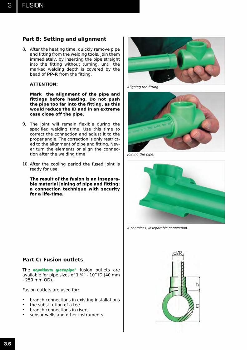
After the heating time, quickly remove pipe 8. and fitting from the welding tools. Join them immediately, by inserting the pipe straight into the fitting without turning, until the marked welding depth is covered by the bead of PP-R from the fitting.
ATTENTION:
Mark the alignment of the pipe and fittings before heating. Do not push the pipe too far into the fitting, as this would reduce the ID and in an extreme case close off the pipe.
The joint will remain flexible during the 9. specified welding time. Use this time to correct the connection and adjust it to the proper angle. The correction is only restrict-ed to the alignment of pipe and fitting. Nev-er turn the elements or align the connec-tion after the welding time.
After the cooling period the fused joint is 10. ready for use.
The result of the fusion is an insepara-ble material joining of pipe and fitting: a connection technique with security for a life-time.
Part C: Fusion outlets
The aquatherm greenpipe® fusion outlets are available for pipe sizes of 1 1⁄4” - 10” ID (40 mm - 250 mm OD).
Fusion outlets are used for:
branch connections in existing installations•the substitution of a tee•branch connections in risers•sensor wells and other instruments•
Aligning the fitting.
Joining the pipe.
A seamless, inseparable connection.

3.7
3Fusion
FusionFusionSiz
e
of
Pipe Size of
Branch
3⁄8”16mm
1⁄2”20mm
3⁄4”25mm
1”32mm
1 1⁄4”40mm
1 1⁄2”50mm
2”63mm
2 1⁄2”75mm
3”90mm
3 1⁄2”110mm
4”125mm
6”160mm
8”200mm
10”250mm
3⁄8” (16 mm) T
1⁄2” (20 mm) R T R
3⁄4” (25 mm) R R T
1” (32 mm) R R R T
1 1⁄4” (40 mm) R/O R/O R T
1 1⁄2” (50 mm) R/O R/O R R T
2” (63 mm) R/O R/O R/O R R T
2 1⁄2” (75 mm) R/O R/O R/O R/O R R T
3” (90 mm) O R/O R/O R/O R R R T
3 1⁄2” (110 mm) O O O O O R R R T
4” (125 mm) O O O O O O R R R T
6” (160 mm) O O O O O O R R T
8” (200 mm) O O O O O O R R R R T
10” (250 mm) O O O O O O R R R R T
T= Tee available R= Reducing tee available O=Fusion outlet
Pipe
size
Thread size
1⁄2” 3⁄4” 1”
3⁄8” (16 mm) R
1⁄2” (20 mm) T R
3⁄4” (25 mm) R T
1” (32 mm) R R T
1 1⁄4” (40 mm) O O
1 1⁄2” (50 mm) O O
2” (63 mm) O O
2 1⁄2” (75 mm) O O O
3” (90 mm) O O O
3 1⁄2” (110 mm) O O O
4” (125 mm) O O O
6” (160 mm) O O O
8” (200 mm) O O O
10” (250 mm) O O O
Part C: Fusion outlets
The aquatherm fusion outlet gives the installer greater flexibility and peace of mind.
Fusion outlets with threaded transitions
Fusion outlet with threaded transitions.
3 Fusion
3.8
Part C: Fusion outlets Prepare tools following the directions out-1. lined on page 3.1 - 3.3.
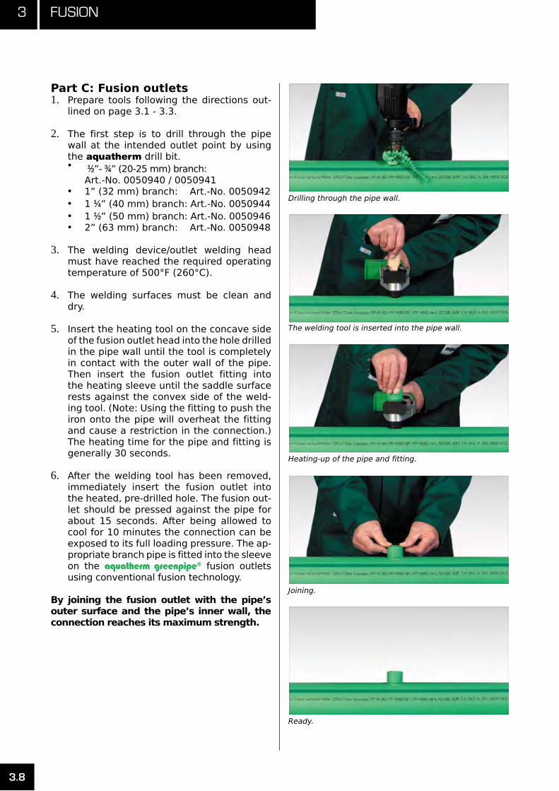
The first step is to drill through the pipe 2. wall at the intended outlet point by using the aquatherm drill bit.
• 1⁄2”- 3⁄4” (20-25 mm) branch: Art.-No. 0050940 / 0050941
1” (32 mm) branch: Art.-No. 0050942•1 • 1⁄4” (40 mm) branch: Art.-No. 00509441 • 1⁄2” (50 mm) branch: Art.-No. 00509462” (63 mm) branch: Art.-No. 0050948•
The welding device/outlet welding head 3. must have reached the required operating temperature of 500°F (260°C).
The welding surfaces must be clean and 4. dry.
Insert the heating tool on the concave side 5. of the fusion outlet head into the hole drilled in the pipe wall until the tool is completely in contact with the outer wall of the pipe. Then insert the fusion outlet fitting into the heating sleeve until the saddle surface rests against the convex side of the weld-ing tool. (Note: Using the fitting to push the iron onto the pipe will overheat the fitting and cause a restriction in the connection.) The heating time for the pipe and fitting is generally 30 seconds.
After the welding tool has been removed, 6. immediately insert the fusion outlet into the heated, pre-drilled hole. The fusion out-let should be pressed against the pipe for about 15 seconds. After being allowed to cool for 10 minutes the connection can be exposed to its full loading pressure. The ap-propriate branch pipe is fitted into the sleeve on the aquatherm greenpipe® fusion outlets using conventional fusion technology.
By joining the fusion outlet with the pipe’s outer surface and the pipe’s inner wall, the connection reaches its maximum strength.
Ready.
Joining.
Heating-up of the pipe and fitting.
The welding tool is inserted into the pipe wall.
Drilling through the pipe wall.

3.9
3Fusion
Part D: Manual welding machine
One wooden transport box for the weldingmachine includes:
one machine body with assembly points for •the remaining parts
one set clamping jaws composed of 8 two-•part jaws bars for pipes and fittings 1⁄2” - 4” ID (25 - 125 mm OD)
one • aquatherm welding head for each of the following diameters: 1 1⁄2” - 4” ID (50 - 125 mm OD)
one welding device Art.-No. 0452341•
one allen key and tool change clamp•
one installation manual•
The manual welding machine was specially de-veloped for stationary welding of pipe and fit-tings with an external diameter of 1 1⁄2” to 4” (50 to 125 mm). This machine is equipped with a hand crank to facilitate a precise pre-assem-bly of complicated installation parts.
The necessary operating instructions are en-closed.
Pipediameter
Weldingdepth
Heatingtime in sec.
Weldingtime
Coolingtime
Nom. I.D.inch
O.D. (mm) inch mmabove +5°C
or 40°Fbelow +5°C
or 40°Fsec. min.
1 1⁄2 50 13⁄16” 20.0 18 27 6 4
2 63 15⁄16” 24.0 24 36 8 6
2 1⁄2 75 1” 26.0 30 45 8 8
3 90 1 1⁄8” 29.0 40 60 8 8
3 1⁄2 110 1 5⁄16” 32.5 50 75 10 8
4 125 1 9⁄16” 40.0 60 90 10 8
Dimensions 6” (160 mm), 8” (200 mm ) and 10” (250 mm): The dimension 6” (160 mm ), 8” (200 mm ) and 10” (250 mm) are joined by butt-welding. Detailed information on butt-welding can be found on pages 3.16-3.18.

3 Fusion
3.10
Part E: Electric welding jig
The aquatherm electric welding jig is engi-neered for use in fabrication shops or on the job site. Its unique clamping system acts both to move the pipe and fittings on and off the welding iron and to hold the pipe and fittings perfectly straight as the fusion connection cools.
Assemble the welding jig by following the in-1. structions included in its carrying case. Im-proper or abusive assembly can cause the sliding clamps to jam. Ensure that all moving and sliding parts are properly lubricated.
Prepare pipe, fittings, and welding iron as 2. directed in parts A and B. Use the blue marking template included with the elec-tric welding jig rather than the green one included with the welding iron.
Set the clamps to the proper positions for 3. the size of pipe you will be using and lock them into place. Use the smaller knob lo-cated on the side of the clamp to adjust for tightness.
Secure the jig to the pipe-end being fused. 4. It is important to secure the pipe at such a depth that it can be properly inserted into the welding tool without the clamp coming into direct contact with the welding head. This is generally ½” to 1” beyond the pre-scribed welding depth.
Secure the fitting tightly against the stop.5.
Electric Welding Jig.
Marking the pipe.
Setting the clamps.
Securing the jig.

3.11
3Fusion
Part E: Electric welding jig
Use the forward action of the jig to gently 6. push the pipe and fitting onto the welding iron. If the jig’s transmission begins click-ing, stop and relax pressure slightly. The larger sizes of pipe and fittings often need time to heat up before they will go onto the welding tools completely. It is best to apply constant low pressure.
Once the pipe and fittings have reached 7. the proper welding depths, relax pressure slightly and begin the heating time.
Once the heating time is complete, use the 8. reverse action of the jig to pull the pipe and fitting free of the welding iron.
Use the forward action of the jig to push the 9. pipe and fitting together until the double ring of PP-R forms. Leave clamps in place for the prescribed weld time. If the joint is being subjected to undue pressure, the clamps should be left in place for the cool-ing phase as well.
Positioning the iron.
Heating the pipe.
Removing the iron.
Completing the weld.

3 Fusion
3.12
Part F: Electrofusion device
The aquatherm electrofusion device was spe-cially developed for electrofusion sockets from 3⁄8” (20 mm) - 6” (160 mm).
Technical information:
supply voltage: 110 V (nominal voltage)•rated frequency: 50 Hz - 60 Hz•protection class: IP 54•
General and inspection
Besides proper workmanship, cleanliness is the most important condition for a proper fusion. To help keep the sockets clean, do not unwrap them until you are ready to install them.
The pipe surface must also be clean and un-damaged. Rougher deformed pipe ends must be cut off.
All parts of the system being fused must have the same temperature (e.g. sun radiation or uncontrolled storage may cause differences in temperature) within the acceptable range of temperature (+41°F to 104°F / +5°C to 40°C).
Part F: Preparation
Carefully follow all the steps in order. Prepara-tion is one of the most important steps of the electrofusion process!
Cut the ends of the pipes squarely and de-1. burr them thoroughly.
Clean and dry the ends of the pipes at the 2. necessary length.
Mark the depth of electro-fusion socket on 3. the end of the pipe.
Peel the surface of both pipes up to the 4. marks thoroughly with a peeling tool (use the peeling tool with the respective pipe di-ameter).
Clean again thoroughly.5.
Electrofusion device 3/8” (20 mm) - 6” (160 mm).
Electrofusion socket.
Peeling tool (Art.-No. 0050558-0050570, up to 75 mm) (from 3” (90 mm) - 6” (160 mm): Art.-No. 0050572 / 0050574 / 0050576 / 0050580 [without picture]).
Welding depth for electrofusion
Size1⁄2”
(20 mm)
3⁄4”
(25 mm)1”
(32 mm)1 1⁄4”
(40 mm)1 1⁄2”
(50 mm)2”
(63 mm)2 1⁄2”
(75 mm)3”
(90 mm)3 1⁄2
(110 mm) 4”
(125 mm)6”
(160 mm)
depth 1 3⁄8” 1 1⁄2” 1 9⁄16” 1 13⁄16” 2” 2 5⁄16” 2 9⁄16” 2 7⁄8” 3 3⁄16” 3 3⁄8” 3 11⁄16”

3.13
3Fusion
Part F: Preparation
Peeling off the outer layer is essential for a proper connection. Damage of the surface such as axial grooves and scratches, is not acceptable in the fusion zone. Avoid touching peeled surfaces and protect them against dirt and grease. Start the fusion process within 30 minutes after peeling.
Assembling the aquatherm electrofusion sockets
Avoid soiling the pipe and fix all parts securely!
Open the protective wrapping of the 1. aqua-therm electrofusion sockets (cut with knife along the edge of the bore), leaving the rest of the foil intact. Clean the inside of the fitting carefully with aquatherm® cleaning wipes. Assemble the fitting within 30 min-utes after opening of the protective foil.
Push the 2. aquatherm electrofusion sockets on the clean and dry end of the pipe (up to the marked depth). Use pressing clamps if necessary.
Remove the protective foil completely and 3. push the other prepared pipe end into the aquatherm electrofusion sockets. Tighten the clamps (if using any).
Make sure the pipes are free from bending or the stress of their own weight within the aqua-therm electrofusion socket. The socket is mov-able at both pipe ends after assembling. The air gap must be even around the circumfer-ence. A stressed or displaced connection can cause an unacceptable melt-flow and a defec-tive connection while joining. The pipe ends and electrofusion sockets must be dry during installation.
Cut, peel and clean the pipes to be welded carefully.
Clean the inner surface of the electrofusion socket.
Push the electrofusion socket onto the pipe end.
Completed electro fusion socket.

3 Fusion
3.14
Part F: Fusion process
Position the fitting with even spacing around 1. the circumference.
Set fusion equipment to the proper sizing.2.
Compare the indications of the fusion 3. equipment with the parameters of the label for accuracy.
Start and monitor the fusion process.4.
Do not move or stress pipe and fitting during the whole fusion process and cooling time. The fused pipe-joint must not be moved (no release of the clamps) or stressed before complete cooling. The minimum required cooling time is marked on each aquatherm electrofusion socket. Ambient temperatures of more than 77°F (25°C) or strong sun-radiation need lon-ger cooling times.
Part F: Working pressure
The aquatherm electrofusion sockets are rat-ed up to 300 psi. The relation between working temperature, pressure load and service life is given in the tables “Working pressure” on page 1.7.
For further information concerning electrofu-sion socket and details about the aquatherm electrofusion device read the enclosed operat-ing instructions.
Kind of stress Compressive stressMinimum waiting period
Tension, bend,torsion of
unpressurized pipes
N/A20 minutes
Test - or work-ing pressure of pipes pressur-
ized
up to 1.5 psi (0.1 bar) 1.5 - 14.5 psi (0.1 - 1 bar)over 14.5 psi (1 bar)
20 minutes60 minutes
120 minutes
Repeating of the welding
processN/A 60 minutes
Push the second pipe - also peeled and cleaned - into the socket.
For a stable welding result it is important that both pipe ends inside the electrofusion socket have parallel faces. Follow the minimum welding depth exactly.
Adjust the socket diameter on the welding device. Start and control the welding process. Observe the prescribed cool-ing time.
RIGHTWRONG

3.15
3Fusion
Part F: Electrofusion device
For pipe repairs using a aquatherm electrofu-sion socket, cut squarely 3-4 lengths of a fitting out of the defective pipe on either side of the defect. Fit the new pipe into this gap. Prepare the ends of the existing pipe including marking of the half length of the fitting.
Peel the new piece of pipe on both sides to the proper depth.
Unwrap two fittings and carefully move the fit-tings over both ends of the repair pipe.
Place the repair-pipe into the gap and move the fittings until they are aligned with the markings on the existing pipes.
Use clamps as needed. Align the pipes care-fully before starting the fusion process. Take care that joint is free from burrs before starting the process.
Heating up.
Repair pin. Cutting.
Part G: Repair tool
There are several ways to repair aquatherm piping systems. For small holes, such as those produced by screws or nails, use the aqua-therm repair tool.
The necessary welding tool (Art.-No. 0050307 - 0050311) and repair pin (Art.-No. 0060600) are described on page 6.36 and 6.37. The installa-tion information is enclosed with the welding tool, but may also be ordered separately.
The aquatherm repair pin can be used to patch small holes and penetrations in the pipe wall. This system is especially useful for holes made by nails or screws.
Assemble the repair tool, following the di-1. rections given in part A.
Clear the hole of any obstructions. This in-2. cludes the penetrating object, any materi-als used to temporarily patch the hole, and any water from the pipe itself. Make sure that the water from the pipe is not in direct contact with the area being repaired.
The repair pin comes in two sizes: ¼” 3. (7mm) and 7⁄16” (11mm). Using a bit that is slightly smaller than the repair tool (3⁄16” for the ¼” pin, 3⁄8” for the 7⁄16” pin), drill out the hole to an appropriate diameter for the re-pair. Remove any burrs or excess material.
Based on the wall thickness of the pipe, 4. mark the repair pin for the appropri-ate depth. Inserting the repair pin too far into the pipe can cause an obstruction.
Once the repair tool has reached the proper 5. welding temperature, insert the repair head into the pre-drilled hole on the pipe. Insert the repair pin into the repair tool. Heat both the hole and the pin for 5 seconds.
Remove the pin from the repair tool and the 6. repair head from the hole. Insert the repair pin into the hole and hold it in place for 15 seconds.
Cut away the unused portion of the repair 7. pin. Wait at least two minutes before turn-ing the system back on.
It is possible to repair larger holes by using a capped fusion outlet. This will allow you to patch holes up to two inches in diameter.
For larger holes or cracks, it is best to simply cut out the pipe and replace it.
3 Fusion
3.16
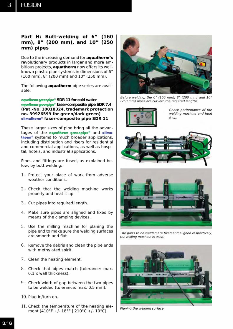
Part H: Butt-welding of 6” (160 mm), 8” (200 mm), and 10” (250 mm) pipes
Due to the increasing demand for aquatherm’s revolutionary products in larger and more am-bitious projects, aquatherm now offers its well-known plastic pipe systems in dimensions of 6” (160 mm), 8” (200 mm) and 10” (250 mm).
The following aquatherm pipe series are avail-able:
aquatherm greenpipe® SDR 11 for cold wateraquatherm greenpipe® faser-composite pipe SDR 7.4(Pat.-No. 10018324, trademark protection no. 39926599 for green/dark green)climatherm® faser-composite pipe SDR 11
These larger sizes of pipe bring all the advan-tages of the aquatherm greenpipe® and clima-therm® systems to much broader applications, including distribution and risers for residential and commercial applications, as well as hospi-tal, hotels, and industrial applications.
Pipes and fittings are fused, as explained be-low, by butt welding:
Protect your place of work from adverse 1. weather conditions.
Check that the welding machine works 2. properly and heat it up.
Cut pipes into required length.3.
Make sure pipes are aligned and fixed by 4. means of the clamping devices.
Use the milling machine for planing the 5. pipe end to make sure the welding surfaces are smooth and flat.
Remove the debris and clean the pipe ends 6. with methylated spirit.
Clean the heating element.7.
Check that pipes match (tolerance: max. 8. 0.1 x wall thickness).
Check width of gap between the two pipes 9. to be welded (tolerance: max. 0.5 mm).
Plug in/turn on.10.
Check the temperature of the heating ele-11. ment (410°F +/- 18°F | 210°C +/- 10°C).
Before welding, the 6” (160 mm), 8” (200 mm) and 10” (250 mm) pipes are cut into the required lengths.
Check performance of the welding machine and heat it up.
The parts to be welded are fixed and aligned respectively, the milling machine is used.
Planing the welding surface.
3.17
3Fusion
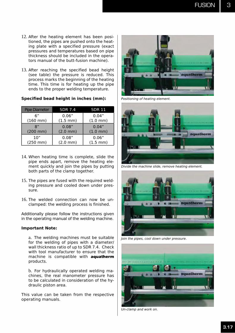
After the heating element has been posi-12. tioned, the pipes are pushed onto the heat-ing plate with a specified pressure (exact pressures and temperatures based on pipe thickness should be included in the opera-tors manual of the butt-fusion machine).
After reaching the specified bead height 13. (see table) the pressure is reduced. This process marks the beginning of the heating time. This time is for heating up the pipe ends to the proper welding temperature.
Specified bead height in inches (mm):
Pipe Diameter SDR 7.4 SDR 11
6”(160 mm)
0.06” (1.5 mm)
0.04”(1.0 mm)
8”(200 mm)
0.08”(2.0 mm)
0.04”(1.0 mm)
10”(250 mm)
0.08”(2.0 mm)
0.06” (1.5 mm)
When heating time is complete, slide the 14. pipe ends apart, remove the heating ele-ment quickly and join the pipes by putting both parts of the clamp together.
The pipes are fused with the required weld-15. ing pressure and cooled down under pres-sure.
The welded connection can now be un-16. clamped: the welding process is finished.
Additionally please follow the instructions given in the operating manual of the welding machine.
Important Note:
The welding machines must be suitable a. for the welding of pipes with a diameter/wall thickness ratio of up to SDR 7.4. Check with tool manufacturer to ensure that the machine is compatible with aquatherm products.
For hydraulically operated welding ma-b. chines, the real manometer pressure has to be calculated in consideration of the hy-draulic piston area.
This value can be taken from the respective operating manuals.
Positioning of heating element.
Divide the machine slide, remove heating element.
Join the pipes, cool down under pressure.
Un-clamp and work on.

3 Fusion
3.18
Part H: Butt-welding reference
aquatherm SDR 11 piping systems butt-welding referencefusion temperature: 410°F +/- 18°F (210°C +/-10°C)
Dimension Adjustment Heating Welding (fusion) Cooling
in.(mm)
adjustmentpressure
height ofbead
(minimum)
Heating time
Heating pressure
max. transition
time
Time of pressure build-up
Welding pressure
Cooling time
6”(160 x 14.6)
155 psi(10.7 bar)
0.039 in.(1.0 mm)
277 sec.15.95 psi(1.1 bar)
8 sec. 13 sec.155 psi
(10.7 bar)24 min.
8”(200 x 18.2)
240.76 psi (16.6 bar)
0.039 in.(1.0 mm)
320 sec.24.66 psi (1.7 bar)
9 sec. 16 sec.240 psi
(16.6 bar)29 min.
10”(250 x 22.7)
377.10 psi (26.0 bar)
0.059 in.(1.5 mm)
368 sec.37.71 psi (2.6 bar)
10 sec. 20 sec.377 psi
(26.6 bar)35 min.
aquatherm SDR 7.4 piping systems butt-welding referencefusion temperature: 410°F +/- 18°F (210°C +/-10°C)
Dimension Adjustment Heating Welding (fusion) Cooling
in.(mm)
adjustmentpressure
height ofbead
(minimum)
Heating time
Heating pressure
max. transition
time
Time of pressure build-up
Welding pressure
Cooling time
6”(160 x 22.1)
221.91 psi (15.3 bar)
0.059 in.(1.5 mm)
361 sec.21.76 psi (1.5 bar)
10 sec. 19 sec.222 psi
(15.3 bar)34 min.
8”(200 x 18.2)
346.64 psi (23.9 bar)
0.079 in.(2.0 mm)
412 sec.34.81 psi (2.4 bar)
11 sec. 23 sec.347 psi
(23.9 bar)42 min.
10”(250 x 22.7)
540.99 psi (37.3 bar)
0.079 in.(2.0 mm)
466 sec.53.66 psi (3.7 bar)
13 sec. 30 sec.541 psi
(37.3 bar)52 min.

3.19
3Fusion
Part I: aquatherm AdvancedPreparation for fusion
The aquatherm greenpipe® Advanced and clima-therm® Advanced systems include a thermal, UV, and vapor barrier, with a thickness ranging from 5⁄16” to 5⁄8”. This barrier serves as suitable insulation in applications where building codes require the pipe the to insulated. In certain ap-plications, the barrier can also help the piping system meet the 25/50 FSI/SDI requirements.
Before beginning the fusion process, the 1. barrier covering the part of the pipe that will be fused must be removed.
Using the marking guide, mark the proper 2. welding depth on the barrier. Then mark the barrier ½” to 1” further away from the end of the pipe. This second mark will help ensure that the barrier does not come into direct contact with the welding tool.
Make an incision lengthwise in the barrier, 3. running from the second mark to the end of the pipe.
Using the second mark as a guideline, 4. make a smooth cut around the circumfer-ence of the pipe. When finished, pull away the barrier at the end of the pipe, exposing a usable welding surface. It is important to remove enough of the barrier so that it will not be exposed to the welding tools during the fusion process.
Once the barrier is removed, proceed with 5. the heat fusion as outlined on pages 3.1 – 3.6, taking care not to damage the barrier.
Be sure to check the newly exposed bar-6. rier for a complete seal. If the cutting or fusion processes have damaged the bond between the barrier and pipe, it is impor-tant to reseal the barrier with a suitable fire-rated tape.
Marking the insulation.
Cutting along the circumference.
Exposed welding surface.

3 Fusion
3.20
Part I: aquatherm Advanced fusion outlet connections
When using fusion outlets on the aquatherm greenpipe® Advanced and climatherm® Ad-vanced systems, it is important to properly remove a sufficient amount of the barrier to allow the welding tool to directly contact the pipe. It is also important to protect the barrier from the welding tool, as the heat can damage the barrier.
Mark the desired location of the branch on 1. the side of the barrier. Make sure the mark is clearly visible.
Using the first mark as the center, make four 2. equidistant marks on pipe, following the di-ameter given in table A. Two of these marks should follow the pipe lengthwise and the other two should be made crosswise. Trace the outside of these marks to form a com-plete circle around the first mark.
Using a sharp utility knife or similar tool, cut 3. along the outside of the line. Be careful not to damage the barrier while cutting. Use a properly sized cutting guide if necessary.
After cutting out the entire circle, remove 4. the barrier from the hole. Use the knife to even out the edges of the cut.
Insulation cut-away diameter
Branch size Cut-away diameter
1⁄2” (20 mm) 1 1⁄2”3⁄4” (25 mm) 1 3⁄4”1” (32 mm) 2”
1 1⁄4” (40 mm) 2 1⁄2”1 1⁄2” (50 mm) 3”
2” (63 mm) 3 3⁄4”
Marking the branch location.
Marking the cut-away diameter.
Cutting along the line.
Removing the insulation.

3.21
3Fusion
Re-mark the pipe in the exact center of the 5. hole. Use the aquatherm drill bit to drill through the pipe wall.
• 1⁄2”- 3⁄4” (20-25 mm) branch: Art.-No. 0050940 / 0050941
1” (32 mm) branch: Art.-No. 0050942•1 • 1⁄4” (40 mm) branch: Art.-No. 00509441 • 1⁄2” (50 mm) branch: Art.-No. 00509462” (63 mm) branch: Art.-No. 0050948•
Insert the welding tool on the concave side 6. of the fusion outlet head into the hole until the head is completely in contact with the outer wall of the pipe. Make sure that the welding head and heating iron never come into direct contact with the barrier. The bar-rier can be protected by covering it with a suitable heat-resistant covering.
Insert the fusion outlet fitting into the heat-7. ing sleeve until the fusion outlet surface rests against the convex side of the weld-ing head. (Note: using the fitting to push the iron onto the pipe will overheat the fit-ting and cause a restriction in the connec-tion.) The heating time for the pipe and fit-ting is approximately 30 seconds in normal conditions and 45 seconds in cold weather installations.
Remove the welding tool and insert the 8. fusion outlet directly into the hole. Apply pressure for at least 15 seconds. Allow the pipe and fitting to cool for approximately 10 minutes before applying load pressure.
Depending on local energy codes and the inter-pretations of the authority having jurisdiction, it may be necessary to insulate over the fusion outlet. Be sure to follow all applicable codes re-garding proper insulation.
In certain applications, the aquatherm Ad-vanced systems can be used to meet flame spread and smoke development requirements.
Drill through the pipe wall.
Inserting welding tool.
Heating pipe and fitting.
Welding fusion outlet into place.

3 Fusion
3.22
Part I: aquatherm Advancedinsulating instructions
For speed and convenience, many contractors install the complete aquatherm piping system and then cover it with insulation barrier, cre-ating aquatherm Advanced on the job site. The aquatherm Advanced system can be in-stalled to achieve the flame spread rating and also for thermal requirements.
Creating the aquatherm Advanced requires the proper sizes of insulation sheets (found on page 6.8) and the fire-rated tape (article num-ber FT25006).
The following process should be followed to create the aquatherm Advanced:
Locate the correctly sized sheet of insula-1. tion.
Line up the edge of the sheet lengthwise 2. with the pipe, making sure that the insula-tion will run parallel to the pipe. Verify that the marking will be facing away from the pipe.
Remove the paper backing from the 3/4” 3. double sided tape and attach the insulation to the pipe. Ensure that the pipe is clean and free of debris before insulating.
Wrap the insulation around the pipe, then 4. remove the paper backing from the 3/4” double sided tape and the foil tape.
Once the insulation is overlapping itself, 5. press down and rub the insulation and tape to ensure a snug smooth fit.
Tape the ends of the insulation to the pipe, 6. sealing the insulation using foil tape (Art.-No. FT25006). Adjoining pieces should be installed next to each other and wrap a piece of foil tape around the full circumfer-ence.
If insulation is required on the fittings, use 7. insulation that provides 1” - 1 1/2” overlap on couplings and tees. Preformed 90° and 45° elbows are available. Tee patterns are also available.
Ensure that all exposed edges are taped 8. closed. The system will not perform prop-erly if there are gaps.
Based on the certified testing, the fittings do not need to be insulated to meet smoke and flame ratings. The heat transfer comparison for insulated and uninsulated fittings can be found on pages 5.3 and 5.4. Local codes may require that the fittings be insulated.
Peel paper back from tape.
Wrap insulation and remove backing from foil tape.
Firmly press along seam to seal edges.
Tape adjoining pieces along the seam the entire circumference.

Installation Principles
Installation concepts
Support techniques
Support intervals
Installation planning
Linear expansion
Bending sideExpansion loop
Pre-stressBellow expansion joint
Length of bending side
Length of bending side with pre-stress
Installation in shafts
Pressure test
Flushing of pipes / GroundingTransport and storage
Fixture connections
Distribution block plumbing and heating


4.1
4installation PrinciPles
Installation concepts for aquatherm
A New Way of Thinking
The aquatherm piping systems offer many in-novative technologies and advantages that can greatly improve the speed and ease of installa-tion. Some of these advantages include:
Fusion connections•Fusion outlets•Lightweight material•Resilient, slightly flexible pipe & connections•Reduced expansion and contraction•
To fully utilize these advantages, a different mindset from metal or even other plastic sys-tems is required.
A Craftsman’s Pipe
As a company, aquatherm takes pride in the systems they manufacture and expects the same from those installing it. No matter how high the quality of the pipe and fittings, the performance of a system will always depend on how carefully and thoughtfully it is installed.
The aquatherm piping systems are designed to look neat and clean when installed, making it easier to expand the system and trace lines.
Planning
As with any system, the speed and accuracy of an aquatherm installation is improved with careful planning. Where possible, pre-measure and pre-cut all lengths of pipe, based on their intended part in the system. This will allow for a greater degree of prefabrication and a lower possibility of error.
A Pre-fab Station
Polypropylene is lighter than most other piping materials, and fusion joints adjust easily to rea-sonable levels of stress from being carried. To take advantage of this, many installers set up a “pre-fab” station on the job site, including a workbench, technical drawings, a welding jig or bench and the appropriate welding tools. This station is used to measure, cut, and prefabri-cate pipe and fittings for the installation. Use of this station ensures adequate space for tool operation.
Pre-assembly
Connections done in a shop or at the “pre-fab” station on the job site are easier and faster to assemble than connections done on pipe that is already in place. It is possible to greatly speed installation by attaching the appropri-ate fittings to one end of the pipe before hang-ing it. Identify the fittings (couplings, elbows, tees, valves) that will go with each length of pipe and fuse them together before hanging the pipe in its proper place. This will allow you to assemble as many as half your connections without any of the complications associated with in-line fusions.
Pre-fabrication
The aquatherm piping systems are light, strong, and somewhat flexible, making them ideal for pre-fabrication. When installing aqua-therm pipe, identify the more complicated as-semblies, such as drop 90’s, flange adaptors, saddle connections, headers, etc., and assem-ble them in-shop or at the “pre-fab” station of the job site. Many installers will assemble whole mechanical rooms in-shop and move the entire assembly to the job site.

4 installation PrinciPles
4.2
Support techniques
Pipe clamps for aquatherm pipes must be sized to match the external diameter of the plastic pipe.
Take care that the support material does not mechanically damage the surface of the pipe (aquatherm pipe clamps Art.-No. 0060516 - 0060654).
The ideal support material for aquatherm pipes are rubber-lined pipe clamps. The rubber compounds are specially made for applications with plastic pipes.
Some types of support materials are designed to allow movement and others are designed to restrict movement entirely.
It is important to distinguish whether the sup-port material is being used as
a fixed point or•a sliding point•
Fixed points
In principle, fixed points are used to divide the pipe into sections, restricting any uncontrolled movement of the pipe.
Fixed points have to be measured and installed in a way that the forces of expansion in aqua-therm pipes, as well as probable additional loads, are accommodated.
When using threaded rods or threaded screws, the drop from the ceiling should be as short as possible. Swinging clamps should not be used as fixed points.
Vertical distributions can be installed using only fixed points. Faser-composite risers do not require expansion loops, provided that fixed points are located immediately before or after a branch.
To compensate for the forces arising from the linear expansion of the pipe, there must be suf-ficient clamps and mountings. The aquatherm pipe clamps meet all requirements, and based on the installation instructions that follow in this chapter are perfect for fixed point instal-lations.
Sliding points
Sliding clamps must allow axial pipe move-ments without damaging the pipe.
When locating a sliding clamp, make sure that movements of the pipelines are not hindered by walls, fittings, or mechanical equipment in-stalled next to the clamps.
Installation advice
The aquatherm pipe clamps are perfectly suit-ed for both fixed point and sliding point instal-lations.
For a fixed-point pipe hanger, a spacer is not used in the hanger except with UV pipe. For a sliding point hanger, the same pipe clamp is used, but with spacers provided to allow move-ment of the pipe.
Fastening
aquatherm greenpipe®
aquatherm greenpipe®
faser -compositepipe
aquatherm greenpipe®
UV pipe
Sliding Point 1 spacer 2 spacers
Fixed point no spacer 1 spacer

4.3
4installation PrinciPles
Support Intervals
aquatherm greenpipe® SDR 11 & climatherm® pipe SDR 11
Pipe diameter
1⁄2” 20mm
3⁄4” 25mm
1” 32mm
1 1⁄4” 40mm
1 1⁄2”
50mm2”
63mm2 1
⁄2” 75mm
3”90mm
3 1⁄2”
110mm4”
125mm6”
160mm8”
200mm10”
250mm
Support intervals (ft)
4 4 4 4 4 4.6 4.9 5.2 5.9 6.6 7.2 7.5 7.9
Support Intervals
aquatherm greenpipe® faser-composite pipe SDR 7.4& climatherm® faser-composite pipe
Table to determine support intervals in conjunction with fluid temperature, ambient temperature at time of installation and pipe size.
Difference in temperature ∆T
Pipe diameter
1⁄2”
20mm
3⁄4”
25mm1”
32mm1 1
⁄4”40mm
1 1⁄2”
50mm2”
63mm2 1
⁄2” 75mm
3” 90mm
3 1⁄2”
110mm4”
125mm6”
160mm8”
200mm10”
250mm
Support intervals (ft)
0°F (-17°C) 4 4.6 5.2 5.9 6.7 7.5 8 8.5 9.5 10.5 11.2 11.3 11.5
36°F(2°C) 4 4 4 4.4 5.1 5.7 6.1 6.4 7.1 7.9 8.9 9 9.2
54°F(12°C) 4 4 4 4.4 5.1 5.7 6.1 6.4 6.9 7.4 8 8.2 8.4
72°F(22°C) 4 4 4 4.1 4.8 5.4 5.7 6.1 6.6 7.1 7.7 7.9 8
90°F(32°C) 4 4 4 4.1 4.8 5.4 5.7 6.1 6.2 6.4 6.7 6.9 7.1
108°F(42°C) 4 4 4 4 4.4 5.1 5.4 5.7 5.9 6.1 6.4 6.6 6.7
126°F(52°C) 4 4 4 4 4.3 4.8 5.1 5.4 5.6 5.7 6.1 6.2 6.4
Pipe clamp distances of vertically installed pipes can be increased by 20% of the tabular values, i.e. to mul-tiply the tabular value by 1.2.

4 installation PrinciPles
4.4
Linear expansion
The linear expansion of pipes depends on the difference between the installation tempera-ture and the operating temperature:
∆ T = Toperating temperature - Tinstallation temperature
Therefore cold water pipes have practically nolinear expansion.
Because of the temperature-dependent expan-sion of the material, the linear expansion must be specially considered in case of warm water and heating installations. This requires a dis-tinction between the types of installation:
concealed installations with piping insulated •installation in ducts•open installation•
aquatherm faser-composite technology
Composed of Fusiolen® PP-R and a specialfaser mixture in the middle layer of the Fusiolen® PP-R material.
The advantages:
resistant against corrosion•linear expansion has been reduced by 75%•flow rate has been increased by 20% at •same loading capacity due to larger inner diameterhigher stability and carrying capacity•higher impact strength•easy processing: simply cut and weld•
Various applications such as:
hot and cold potable water•food processing•heating systems•rainwater•compressed air systems•swimming pool installations•pipelines for industrial use•
Installation planning
All fusion connections require a certain amount of space, as well as mobility, around each joint. When installing an aquatherm piping system, it is important to be conscious of the workspace in which each fusion will be performed. A mea-sure of planning and foresight can greatly im-prove the speed and ease of an installation.
A minimum of 7” of free space around the pipe is recommended for freehand socket fusions. A minimum of 24” of free space is recommended when working with the electric welding jig or the butt fusion machine. If a pipe must pass through an area that is dif-ficult to access, aquatherm recommends pre-fabricating all the connections that will be in that area. Once these connections are complet-ed, the assembled pipe and fittings can be set into place and joined to the main system with fusions done in a more accessible location.
Concealed installation with insu-lated piping
Concealed installations generally do not require consideration for the expansion of aquatherm piping systems.
In general, insulation gives enough expansion space for the pipe. In the case where the ex-pansion is greater than the room to move in the insulation, the material absorbs any stress arising from a residual expansion.
The same applies to pipes which do not have to be insulated according to current regulations.
Embedding the pipe in concrete or plaster will negate most of the linear expansion. The com-pressive strain and tensile stress arising from this are no longer critical, as the extra forces are absorbed by the pipe itself. This is also true of directly buried pipe.

4.5
4installation PrinciPles
Open installation
In the case of exposed installation pipes (e.g. in the basement), excellent visual characteris-tics and form stability are important. The aqua-therm greenpipe® and climatherm® faser-compos-ite pipes for hot water and heating systems make this possible. The coefficient (α) of linear expansion of aquatherm greenpipe® and clima-therm® faser-composite pipes is only
α faser-composite = 0.035 mm/mK = 2.367•10-4”/ft°F
and comparable to the linear expansion of metal pipes.
The coefficient of linear expansion of aqua-therm piping systems without stabilizing com-ponents is
α fusiotherm= 0.150 mm/mK = 1.008•10-3”/ft°F
The aquatherm faser-composite pipes must have enough space to expand (see page 4.06). An expansion control is required for long and straight faser-composite pipes (over 120 ft).
The aquatherm pipes without the stabilizing compound should have expansion control on every 30 ft of straight runs. Risers of faser-composite pipes may be installed rigidly with-out expansion compensation. The following formula, calculation examples, data tables and diagrams help to determine the linear expan-sion. The difference between working temper-ature and maximum or minimum installation temperature is essential for the calculation of linear expansion.
Calculation of the linear expansion
Calculation example: Linear expansion
Given and required values
Symbol Meaning ValueMeasuring
Unit
∆ʅ Linear expansion ?in⁄ft°F
mm⁄m°K
α 1 Coefficient of linear expansion
aquathermfaser-composite pipe
2.367•10 -4 in⁄ft°F
0.035 mm⁄m°K
α 2 Coefficient of linear expansion aquatherm pipe
1.008•10 -3 in⁄ft°F
0.15 mm⁄m°K
L Pipe length100 ft
30.5 m
TW Working temperature160 °F
71.0 °C
TM Installation temperature60 °F
15.6 °C
∆TTemperature difference be-
tween working and installation temperature (∆T = TW – TM)
100 °F
38.0 °K
∆T [°F] • 5⁄9 = ∆T [°K]
The linear expansion ∆ ʅ is calculated according to the following formula:
∆ʅ = α • L • ∆T
Material: aquatherm faser-composite pipe(α = 0.035 mm⁄mK)
∆ʅ = 2.367 • 10-4 • 100 ft • 100°F
∆ʅ = 2.4 in.
0 1 2 3 4 5 6 7 8 9 10 11 12
80
70
60
50
40
30
20
10
0
Lengthexpansioncomparison:faser-compositeto standardPP-pipe
→ T
em
pera
ture
diffe
rence
∆T (
K)
→ Expansion ∆ʅ in mm⁄m
Faser-composite pipe Standard PP-pipe→ →
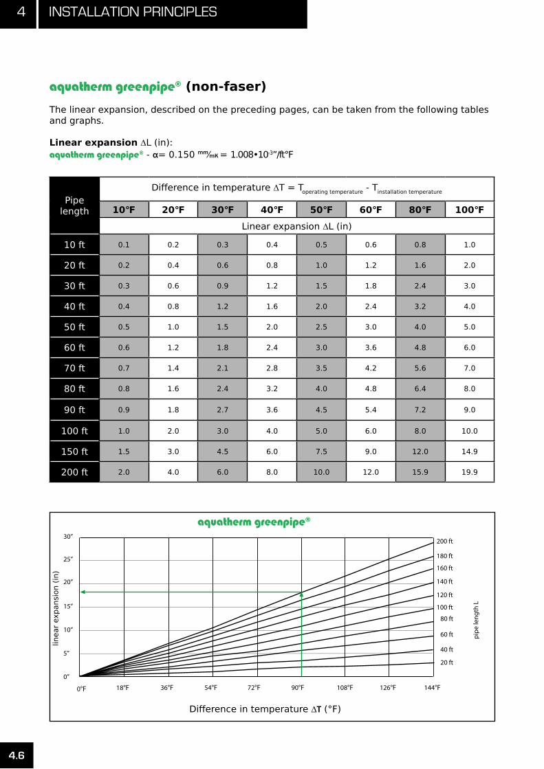
4 installation PrinciPles
4.6
aquatherm greenpipe® (non-faser)
The linear expansion, described on the preceding pages, can be taken from the following tablesand graphs.
Linear expansion ∆L (in):aquatherm greenpipe® - α= 0.150 mm⁄mK = 1.008•10-3”/ft°F
Pipelength
Difference in temperature ∆T = Toperating temperature - Tinstallation temperature
10°F 20°F 30°F 40°F 50°F 60°F 80°F 100°F
Linear expansion ∆L (in)
10 ft 0.1 0.2 0.3 0.4 0.5 0.6 0.8 1.0
20 ft 0.2 0.4 0.6 0.8 1.0 1.2 1.6 2.0
30 ft 0.3 0.6 0.9 1.2 1.5 1.8 2.4 3.0
40 ft 0.4 0.8 1.2 1.6 2.0 2.4 3.2 4.0
50 ft 0.5 1.0 1.5 2.0 2.5 3.0 4.0 5.0
60 ft 0.6 1.2 1.8 2.4 3.0 3.6 4.8 6.0
70 ft 0.7 1.4 2.1 2.8 3.5 4.2 5.6 7.0
80 ft 0.8 1.6 2.4 3.2 4.0 4.8 6.4 8.0
90 ft 0.9 1.8 2.7 3.6 4.5 5.4 7.2 9.0
100 ft 1.0 2.0 3.0 4.0 5.0 6.0 8.0 10.0
150 ft 1.5 3.0 4.5 6.0 7.5 9.0 12.0 14.9
200 ft 2.0 4.0 6.0 8.0 10.0 12.0 15.9 19.9
aquatherm greenpipe®
Difference in temperature ∆T (°F)
30”
25”
20”
15”
10”
5”
0”
18°F 36°F 54°F 72°F 90°F 108°F 126°F 144°F
200 ft
180 ft
160 ft
140 ft
120 ft
100 ft
80 ft
60 ft
40 ft
20 ft
Fusiotherm¨-pipe
Difference in temperature ∆ [ °F]
pipe
leng
th L
0°F
linear
expansi
on (
in)
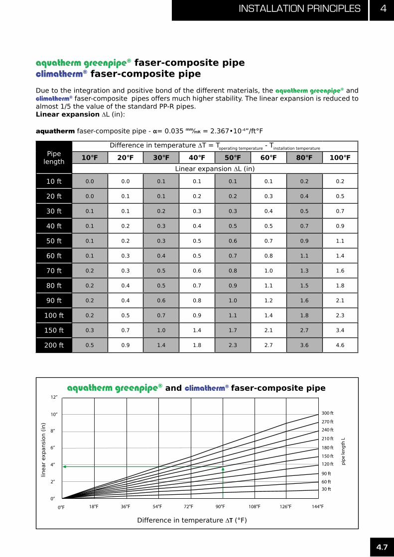
4.7
4installation PrinciPles
aquatherm greenpipe® faser-composite pipeclimatherm® faser-composite pipe
Due to the integration and positive bond of the different materials, the aquatherm greenpipe® and climatherm® faser-composite pipes offers much higher stability. The linear expansion is reduced to almost 1/5 the value of the standard PP-R pipes.Linear expansion ∆L (in):
aquatherm faser-composite pipe - α= 0.035 mm⁄mK = 2.367•10-4”/ft°F
Pipelength
Difference in temperature ∆T = Toperating temperature - Tinstallation temperature
10°F 20°F 30°F 40°F 50°F 60°F 80°F 100°F
Linear expansion ∆L (in)
10 ft 0.0 0.0 0.1 0.1 0.1 0.1 0.2 0.2
20 ft 0.0 0.1 0.1 0.2 0.2 0.3 0.4 0.5
30 ft 0.1 0.1 0.2 0.3 0.3 0.4 0.5 0.7
40 ft 0.1 0.2 0.3 0.4 0.5 0.5 0.7 0.9
50 ft 0.1 0.2 0.3 0.5 0.6 0.7 0.9 1.1
60 ft 0.1 0.3 0.4 0.5 0.7 0.8 1.1 1.4
70 ft 0.2 0.3 0.5 0.6 0.8 1.0 1.3 1.6
80 ft 0.2 0.4 0.5 0.7 0.9 1.1 1.5 1.8
90 ft 0.2 0.4 0.6 0.8 1.0 1.2 1.6 2.1
100 ft 0.2 0.5 0.7 0.9 1.1 1.4 1.8 2.3
150 ft 0.3 0.7 1.0 1.4 1.7 2.1 2.7 3.4
200 ft 0.5 0.9 1.4 1.8 2.3 2.7 3.6 4.6
aquatherm greenpipe® and climatherm® faser-composite pipe
Difference in temperature ∆T (°F)
12”
10”
8”
6”
4”
2”
0”
18°F 36°F 54°F 72°F 90°F 108°F 126°F 144°F
300 ft
270 ft
240 ft
210 ft
180 ft
150 ft
120 ft
90 ft
60 ft30 ft
Fusiotherm¨-faser composite pipe
Difference in temperature ∆ [ F]
pipe
leng
th L
0°F
linear
expansi
on (
in)

4 installation PrinciPles
4.8
Linear expansion due to temperature differ-ence between operating temperature and in-stallation temperature can be addressed with different installation techniques.
Bending side
In most cases, directional changes can be used to compensate for linear expansion in pipes.
The values of the bending side can be taken directly from the tables and graphs on the fol-lowing pages.
Symbol Meaning
LBS
Length of the bend-ing side
(in) (mm)
KMaterial specific constant
2.98 15
d Outside diameter (mm) (mm)
∆ʅ Linear expansion (in) (mm)
L Pipe Length (ft) (m)
FP Fixed point
SP Sliding point
Calculation of the bending side length:
LBS = K • √ d • ∆ʅ
Expansion loop
If the linear expansion cannot be compensated for by a change in direction, it may be neces-sary to install an expansion loop.
In addition to the length of the bending side LBS, the width of the pipe bend Amin must be considered.
Symbol Meaning
Amin Width of the expansion loop (in)
SD Safety distance 6 in
The pipe bend Amin is calculated according to the following formula:
Amin = 2 • ∆ʅ + SD
Continuing the example from the previous page, with ∆ʅ = 1.4 in, the width of the expan-sion loop should be at least (2 • 1.4) + 6 = 8.8 in.

4.9
4installation PrinciPles
Pre-stress
Where space is limited, it is possible to shorten the total width Amin as well as the length of the bending side LBSV by pre-stressing.
Pre-stressing during installation, if planned and carried out properly, offers a visually perfect installation, as the linear expansion is not no-ticeable in the operating system.
The side length LSV is calculated according to the following calculation example:
Symbol Meaning ValueMeasuring
Unit
LBSV
Length of pre-stress - in
The side length of expansion loops with pre-stress is calculated according to the following example:
LBSV = K • √ d • ∆ʅ⁄2
As noted previously, the value of K is a material constant (2.98), d is the pipe outside diameter in mm and ∆ʅ is the previously calculated ther-mal expansion.
Bellow expansion joint
All bellow expansion joints designed for metal materials are unsuitable for use with aqua-therm piping systems. When using axial ex-pansion joints, observe the manufacturer’s in-structions.

4 installation PrinciPles
4.10
The length of the bending side LBS can be taken from the following tables and diagrams with con-sideration of the applied pipe dimensions and determined linear expansion.
Length of bending side for aquatherm greenpipe®, aquatherm greenpipe® faser-composite pipe, and climatherm® faser-composite pipe.
Pipe dimension
in inch (mm)
Linear expansion in inches (“)
1” 2” 3” 4” 5” 6” 7” 8” 9” 10” 11” 12”
Length of bending side (in)
1⁄2” (20) 13 19 23 27 30 33 35 38 40 42 44 46
3⁄4” (25) 15 21 26 30 34 37 40 42 45 47 50 52
1“ (32) 17 24 29 34 38 42 45 48 51 54 56 59
11⁄4“ (40) 19 27 33 38 42 46 50 54 57 60 63 66
11⁄2“ (50) 21 30 37 42 47 52 56 60 64 67 70 73
2“ (63) 24 34 41 48 53 58 63 67 71 75 79 82
21⁄2“ (75) 26 37 45 52 58 64 69 73 78 82 86 90
3“ (90) 28 40 49 57 64 70 75 80 85 90 94 99
31⁄2“ (110) 31 44 54 63 70 77 83 89 94 99 104 109
4“ (125) 34 47 58 67 70 82 89 95 101 106 111 116
6“ (160) 38 54 66 76 85 93 100 107 114 120 126 131
8“ (200) 42 60 73 85 95 104 112 120 127 134 141 147
10“ (250) 47 67 82 95 106 116 125 134 142 150 157 164
2.5ft
2.0ft
1.5ft
1.0ft
0.5ft
0.0ft
1” 2” 4” 5” 7”
10” (250 mm)
8” (200 mm)
6” (160 mm)
4” (125 mm)
3 1/2” (110 mm)
3” (90 mm)
2 1/2” (75 mm)
2” (63 mm)
1 1/4” (40 mm)1” (32 mm)
Linear expansion ∆ L [inch]
3.0ft
3.5ft
4.0ft
4.5ft
3” 6” 8” 9” 11”10” 12”
1 1/2” (50 mm)
3/4” (25 mm)1/2” (20 mm)
Len
gth
of b
en
din
g s
ide
[ft
]
pip
e d
ime
nsio
n
0”
Length
of
bendin
g s
ide (
ft)
Linear expansion ∆ L (inch)
pip
e d
imensi
on
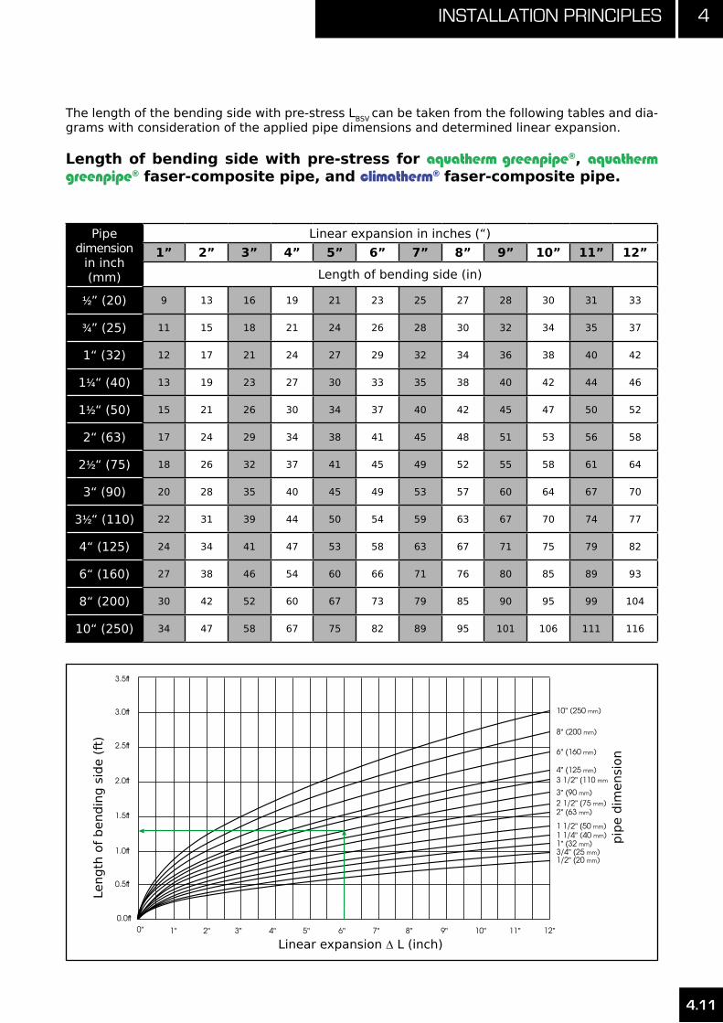
4.11
4installation PrinciPles
The length of the bending side with pre-stress LBSV can be taken from the following tables and dia-grams with consideration of the applied pipe dimensions and determined linear expansion.
Length of bending side with pre-stress for aquatherm greenpipe®, aquatherm greenpipe® faser-composite pipe, and climatherm® faser-composite pipe.
Pipe dimension
in inch (mm)
Linear expansion in inches (“)
1” 2” 3” 4” 5” 6” 7” 8” 9” 10” 11” 12”
Length of bending side (in)
1⁄2” (20) 9 13 16 19 21 23 25 27 28 30 31 33
3⁄4” (25) 11 15 18 21 24 26 28 30 32 34 35 37
1“ (32) 12 17 21 24 27 29 32 34 36 38 40 42
11⁄4“ (40) 13 19 23 27 30 33 35 38 40 42 44 46
11⁄2“ (50) 15 21 26 30 34 37 40 42 45 47 50 52
2“ (63) 17 24 29 34 38 41 45 48 51 53 56 58
21⁄2“ (75) 18 26 32 37 41 45 49 52 55 58 61 64
3“ (90) 20 28 35 40 45 49 53 57 60 64 67 70
31⁄2“ (110) 22 31 39 44 50 54 59 63 67 70 74 77
4“ (125) 24 34 41 47 53 58 63 67 71 75 79 82
6“ (160) 27 38 46 54 60 66 71 76 80 85 89 93
8“ (200) 30 42 52 60 67 73 79 85 90 95 99 104
10“ (250) 34 47 58 67 75 82 89 95 101 106 111 116
Linear expansion ∆ L [inch]
Len
gth
of b
en
din
g s
ide
[ft
]
pip
e d
ime
nsio
n
2.5ft
2.0ft
1.5ft
1.0ft
0.5ft
3.0ft
3.5ft
1” 2” 4” 5” 7”3” 6” 8” 9” 11”10” 12”0”
4.11
0.0ft
10” (250 mm)
8” (200 mm)
6” (160 mm)
4” (125 mm)3 1/2” (110 mm)
3” (90 mm)2 1/2” (75 mm)2” (63 mm)
1 1/4” (40 mm)1” (32 mm)
1 1/2” (50 mm)
3/4” (25 mm)1/2” (20 mm)
Length
of
bendin
g s
ide (
ft)
Linear expansion ∆ L (inch)
pip
e d
imensi
on
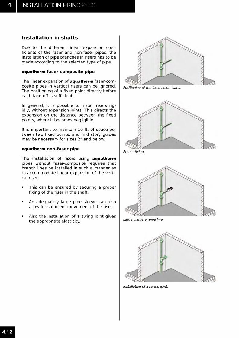
4 installation PrinciPles
4.12
Installation in shafts
Due to the different linear expansion coef-ficients of the faser and non-faser pipes, the installation of pipe branches in risers has to be made according to the selected type of pipe.
aquatherm faser-composite pipe
The linear expansion of aquatherm faser-com-posite pipes in vertical risers can be ignored. The positioning of a fixed point directly before each take-off is sufficient.
In general, it is possible to install risers rig-idly, without expansion joints. This directs the expansion on the distance between the fixed points, where it becomes negligible.
It is important to maintain 10 ft. of space be-tween two fixed points, and mid story guides may be necessary for sizes 2” and below.
aquatherm non-faser pipe
The installation of risers using aquatherm pipes without faser-composite requires that branch lines be installed in such a manner as to accommodate linear expansion of the verti-cal riser.
This can be ensured by securing a proper •fixing of the riser in the shaft.
An adequately large pipe sleeve can also •allow for sufficient movement of the riser.
Also the installation of a swing joint gives •the appropriate elasticity.
Positioning of the fixed point clamp.
Proper fixing.
Large diameter pipe liner.
Installation of a spring joint.

4.13
4installation PrinciPles
Pressure test / Test control
While still visible all pipelines must be hydrauli-cally pressure tested. The test pressure must be 1.5 times of the operating pressure.
When performing the pressure test, the mate-rial properties of aquatherm pipes can lead to an expansion of the pipe. This influences the test results. A further influence of the test re-sult can be caused by the coefficient of ther-mal expansion of aquatherm pipes. Different temperatures of the pipe and the test medium lead to alterations of pressure. A temperature change of 18°F corresponds to a pressure dif-ference of 7.25 to 14.5 psi (0.5 to 1 bar). There-fore the highest possible constant temperature of the test medium must be measured during the hydraulic pressure test.
The hydraulic pressure test requires a prelimi-nary, principal, and final test.
For the preliminary test, a test pressure of 150% of the highest possible operating pres-sure must be produced. This test pressure must be re-established twice within 30 minutes within a 10 minute interval. After a test time of a further 30 minutes the test pressure must not drop more than 8.7 psi (0.6 bar) and no leak-age should have appeared.
The preliminary test is to be followed directly by the principal test. Test time is 2 hours. The test pressure taken from the preliminary test may not fall more than 3 psi (0.2 bar).
After completion of the preliminary and princi-pal tests, the final test must be conducted with an alternating test pressure of 150% and 15% in a rhythm of at least 2 minutes with final in-tervals of 5 minutes.
Between each test phase, the pressure has to be removed.
No leakage must appear at any point of the tested installation.
Measuring of the test pressures
Measuring must be done with a manometer al-lowing a perfect reading of a pressure change of 1.45 psi (0.1 bar). The manometer has to be placed at the lowest point of the installation.
Test record
A record of the hydraulic pressure test must be prepared and signed by the client and contrac-tor stating place and date (see page: 4.16)
IMPORTANT:This test is required by the manufacturer for the validation of the aquatherm war-ranty. This does not supersede or replace regulations placed by the local code au-thority having jurisdiction.
Test should be faxed to aquatherm at:801-494-1053 for the United States•403-770-8326 for Canada•
Tests may also be e-mailed to:[email protected]

4 installation PrinciPles
4.14
Preliminary & Principal Test:
Bring pressure in system up to 150% of the 1. maximum operating pressure.
Wait 10 minutes, then check the pressure, 2. and if there has been any decrease due to expansion of the piping, raise pressure back to 150% of the maximum operating pressure.
Repeat step 2.3.
Wait 30 minutes then read pressure. 4. Pressure must not drop more than 9 psi (0.6 bar) below 150% of the maximum operating pressure.
Wait 120 minutes (2 hours) then read 5. pressure. Pressure must not drop more than 3 psi (0.2 bar) from previous reading in step 4.
If the system has met the requirements of 6. steps 4 and 5, continue to the final test.
Final Test:
Bring pressure in system up to 150% of the 1. maximum operating pressure (MOP) and wait 2 minutes.
Drop pressure to 15% MOP and wait 2 2. minutes.
Bring pressure in system up to 150% and 3. wait 2 minutes.
Drop pressure to 15% MOP and wait 2 4. minutes.
Bring pressure in system up to 150% and 5. wait 2 minutes.
Drop pressure to 15% MOP and wait 2 6. minutes.
Bring pressure in system up to 150% and 7. wait 5 minutes.
Drop pressure to 15% MOP and wait 5 8. minutes.
No leakage may appear at any point of the tested installation.
Example aquatherm piping system pressure test:

4.15
4installation PrinciPles
30 min 60 min
∆pmax = 9 psi (0.6 bar)
∆pmax =3 psi(0.2 bar)
180 min
t in min
p in
psi
(ba
r)150 %Maxoperatingpressure
Preliminary test
Preliminary - and principal test
t in min
15%MaxOperatingPressure
150%Max OperatingPressure
2 min 4 min 5 min 10 min2 min 4 min 2 min 4 min
Final test

4 installation PrinciPles
4.16
Description of the installation
Place:
Object:
Pipe- 1/2” (20 mm) ft/mlengths: 3/4” (25 mm) ft/m 1” (32 mm) ft/m 1 1/4” (40 mm) ft/m 1 1/2” (50 mm) ft/m 2” (63 mm) ft/m 2 1/2” (75 mm) ft/m 3” (90 mm) ft/m 3 1/2” (110 mm) ft/m 4” (125 mm) ft/m 6” (160 mm) ft/m 8” (200 mm) ft/m 10” (250 mm) ft/m
Highest point: ft/m (over manometer)
Start of the test:
End of the test:
Test period:
Client:
Contractor:
Place:
Date:
Stamp / Signature
Preliminary test
150% of max. working pressure psi (bar)
Pressure drop after 30 minutes: psi (bar) (max. 8.7psi / 0.6bar)
Result preliminary test:
Principal test
Working pressure: psi (bar) (Result preliminary test)
Pressure after 2 hours: psi (bar)
Result principal test:
Final test
1.Working pressure 150%: psi (bar) at least 2 minutes, then
Working pressure 15%: psi (bar) at least 2 minutes
2.Working pressure 150%: psi (bar) at least 2 minutes, then
Working pressure 15%: psi (bar) at least 2 minutes
3.Working pressure 150%: psi (bar) at least 2 minutes, then
Working pressure 15%: psi (bar) at least 2 minutes
4.Working pressure 150%: psi (bar) at least 5 minutes, then
Working pressure 15%: psi (bar) at least 5 minutes
Test should be faxed to aquatherm at:
801-494-1053 for the United States•403-770-8326 for Canada•
Tests may also be e-mailed to:[email protected]

4.17
4installation PrinciPles
Flushing of pipes
All water systems, independent of their mate-rial, should be flushed thoroughly after their installation. The following requirements must be complied with before the installation can be put into service:
protection of the water quality•avoidance of corrosion damage•avoidance of malfunctions of pumps and •apparatusescleanliness of the inner surface of the pipe•
These requirements are met by:
flushing with water•flushing with air-water-mixture•
The flushing medium may be determined by local codes, engineering specifications or the needs of the mechanical equipment used.
Where no requirements are established, pota-ble water is sufficient for flushing aquatherm piping materials.
Grounding
Most building codes require that grounding be provided for all conductive components inside the structure. It is important to note that aqua-therm pipes do not carry electrical currents and cannot be used to provide grounding. An alternative method of grounding is required.
Where metal pipes are replaced by PP-R pipes, the ground can not be created by the piping system. An alternative ground system must be installed.
The grounding system should be inspect-ed by a qualified electrician.
Outdoor installation
In applications where the installed pipe will be exposed to UV-radiation (such as outdoor ap-plications), it is recommended that aquatherm greenpipe® UV or climatherm® UV be used. This pipe is engineered with an outer coating that protects the pipe from the aging and discolor-ation that can occur from prolonged exposure to UV-radiation. See page 6.5 - 6.6.
Freeze protection
The aquatherm piping systems may be in-stalled in applications and conditions where freezing may occur.
Generally, freezing the pipes and the water in them will not cause problems for the piping materials. However freezing may cause prob-lems for the user, if the system is required to be operational during these freezing periods.
To avoid this, anti-freeze (glycerin or glycol) or heating cables applied externally or inside the pipe may be used to ensure the system does not freeze.
Regardless of the method chosen, all products must be used in accordance with the freeze protection system manufacturer’s recommen-dations, the product/system listings, and shall be used in compliance with all applicable local codes.
When using any type of external heat source applied to the piping, such as heat tape or heat-ing cables, the product must be suitable for use with plastic piping. Additionally, the heat system must be self-regulating and ensure the surface temperature of the aquatherm pipe and fittings will not exceed 70°C.
Transport and storage
The aquatherm greenpipe® and climatherm® pipes may be stored outside at any temperature. Pro-viding a solid, flat, and level base for the pipe is very important to avoid a deformation of the pipes while in transport and storage. Improper storage of pipe can cause bowing.
At temperatures below 0°C (32°F), it is possible to damage the pipes through strong impacts. In spite of its high impact resistance, the mate-rial must be treated with caution at low tem-peratures.
UV-radiation has detrimental effects on all high polymer plastics. Maximum outdoor storage time is 6 months if removed from factory-supplied UV-protected bags.

4 installation PrinciPles
4.18
aquatherm greenpipe® connecting wall disk in sound insulating cleating, i.e. in a pipe chase or for concealed installation.
aquatherm greenpipe® wall disks for twin fixture con-nections with galvanized mounting plate and sound absorption plate from the fixing program (gauge for bore holes 8.7/6/3.2 in.).
Mounting unit twin including 2 aquatherm green-pipe® transition elbows female/male with counter nut, joint ring and curved washer.
aquatherm greenpipe® cavity wall disk installed in a pipe chase.
aquatherm greenpipe® transition elbow female / male for cavity wall connection with 1” thread.
aquatherm greenpipe® cavity wall fitting joint with aquatherm greenpipe® transition elbow.
The aquatherm greenpipe® transition elbow with female/male thread can be used for flushing box connections. This transition elbow is also available with a single mounting unit.
Fixture connections

4.19
4installation PrinciPles
Distribution block: example of applications
The stamped numbers 1 and 2 indicate the proper connection of the aquatherm greenpipe® distribution block. They provide assistance with the installation.
For the “heating” connection schematic (A), the return is connected to the supply chan-nel marked 1 and the flow to supply channel marked 2. The connections can also be used in reverse.
For the potable water connection schematic (B), supply channel 1 is intended for the cold water pipe and supply channel 2 for the hot water pipe connection. In factory condition, the lower outlets are closed. The connection with supply channel 2 is made by drilling out the opening (1/2” drill bit). Thus an additional pipe can be connected.
By turning the aquatherm greenpipe® distribu-tion block, a mirror-image connection can be made. These schematics are presented in the illustrations C and D.
The flow and return connections of the aqua-therm greenpipe® distribution block are installed with 1/2” (20 mm) pipes. For radiator connec-tions, 3/8” (16 mm) pipes must be welded into the outflow sockets of the distribution block.
The aquatherm greenpipe® distribution block plumbing must be connected with 3/4” (25 mm) pipes. For pipe connections to the taps, 1/2” (20 mm) pipes must be welded into the outflow sockets of the distribution block.
Heating
flow flow
flowreturn
return return
hotwater
hotwater
hotwater
coldwater
coldwater
coldwater
hot water return
Plumbing
Heating
flow flow
flow return
return return
hotwater
hotwater
hotwater
coldwater
coldwater
coldwater
hot water return
Plumbing

4 installation PrinciPles
4.20
The connection pipes in the individual floors or risers are connected for hot and cold water with aquatherm greenpipe® or aquatherm greenpipe® faser-composite pipes with an external diameter of 3/4” (25 mm). The same also applies for the hot water return which can be led back from any aquatherm greenpipe® distribution block.
Reducers for further pipe systems can be welded directly onto the distribution block.
The supplied 3/4” (25 mm) end plug seals off a through-flow unit or, alternatively, the 3/8” (16 mm) end cap. By cutting the end of the plug, it can be used as 3/4” (25 mm) to 3/8” (16 mm) re-ducer or as 3/8” (16 mm) socket.
By turning the aquatherm greenpipe® distribution block and drilling out the factory-sealed outlets, it is possible to create compact connection ar-rangements even in areas of restricted space. This avoids the time-consuming operation of guiding under or over pipes and the associated sealing work.

4.21
4installation PrinciPles
Insulation for distribution block
It is also possible to install the compact distri-bution block by using a specially adapted insu-lation. In this case, the junction not only avoids the crossing of pipes, but also the extra work involved in the expensive insulation of the dou-ble tee-branch.
The insulation for the aquatherm greenpipe® dis-tribution block is made from high-quality PPO/PS rigid expanded polyurethane.
Dimensions of insulation
Thermal conductivity: 0.28• BTU-in⁄hr •°F • ft2
Length: 7.25 in•Width: 4.69 in•Height: 2.76 in•
The accessories (1 plug, 2 fastening plugs) areintegrated in the insulation of a supply unit aquatherm greenpipe® distribution block with in-sulation tray (Art.-No. 30130, see picture).
aquatherm greenpipe® distribution block
If the radiator connection is not in the immedi-ate vicinity of the pipe connection of the distri-bution block, this supply can be arranged with a 3/8” (16 mm) pipe by welding-in of two re-ducers.

4 installation PrinciPles
4.22
return
flow
return
flow
aquatherm greenpipe® distribution block: example of applications - hydronics
The flow and return connections of heating pipes to the aquatherm greenpipe® distribution block with aquatherm greenpipe® or aquatherm greenpipe® faser-composite pipes of an external diameter of 1/2” (20 mm). Used in conjunction with the aquatherm® connecting bend (Art.-No. 85120) and the aqua-therm® radiator valves, the outgoing 3/8” (16 mm) pipe connections are ideal for radiator connec-tions.
It doesn’t matter where the heating flow or return is connected to the aquatherm greenpipe® distri-bution block. A simple turn of the distribution block adapts it to the appropriate specification.

Planning
PlanningFlame spread and smoke developmentaquatherm Advanced
Insulation calculations
Pipe sizingPrinciples of calculation
Commercial water pipe sizing
Maximum flow rateFlow velocity and head loss
Pipe friction factor and calculated flow rate
Equivalent lengths of aquatherm greenpipe® fittings


5.1
5Planning
aquatherm greenpipe® Advancedclimatherm® Advanced
Taking convenience and versatility to a whole new level, aquatherm Advanced systems combine fire protection, vapor barrier, and thermal insulation into an external wrap, creat-ing piping systems that are truly complete.
The aquatherm Advanced systems use an in-sulation wrap, providing acceptable insulation for most applications. By capitalizing on the natural insulation of the PP-R material, aqua-therm Advanced is able to offer the most ef-ficient insulation value for the application (see page 5.3). The aquatherm Advanced system is ideally suited for:
heating and cooling installations•potable hot and cold installations•non-combustible construction•
The insulation for the aquatherm Advanced generally meets or exceeds the heat transfer requirements for 1 1/2 inches of insulation, as given in ASHRAE and ICC energy codes. The tables on pages 5.3 and 5.4 give the approxi-mate equivalent values.
The insulation wrap also meets an FSI of 25 and an SDI of 50, making the system safe for use in:
return air plenums•exposed installation in high-rise buildings•non-combustible construction•
The aquatherm Advanced utilizes standard aquatherm greenpipe® and climatherm® pipe lengths and fittings to simplify installation. For full instructions, see page 3.19.
Planning and engineering with aquatherm
With unique advantages over both metal and other plastic systems, aquatherm piping sys-tems offer new possibilities for design and ap-plication. By combining revolutionary strength and longevity with industry-leading purity and neutrality, aquatherm manufactures piping systems that can truly address all possible con-cerns for potable, food-grade, hydronic, chemi-cal and industrial applications.
When designing with aquatherm piping sys-tems, it is important to be aware of its unique features, such as the faser-composite for ex-pansion control, the fusion connections, the impact and chemical resistance, and the sound insulation, as well as others.
In particular, the natural r-value and reduced friction factors help make the system more en-ergy efficient. With careful planning and engi-neering, it is possible to exceed existing per-formance standards and maximize a system’s efficiency.
Be sure to verify all calculations before install-ing an aquatherm piping system. The values given in this catalog are intended for general reference and are not a substitute for actual engineering.
Flame spread and smoke development
The aquatherm greenpipe® and climatherm® sys-tems do not produce toxic by-products during combustion. In a fully developed fire, Fusiolen® PP-R will only produce CO2 and H2Ogas. In an under-developed fire, trace amounts of CO can be produced, but this is common in all combus-tible materials, such as wood and paper.
Many building codes do not consider the toxic-ity of the smoke produced, or lack thereof, but rather focus only on the volume and opacity of the smoke. Therefore, it is important to install only pipe that meets local code requirements. These codes generally reference ASTM E84 in the United States and CSA S-102.2 in Canada and require that the installed pipe have a Flame Spread Index of 25 or less and Smoke Develop-ment Index of 50 or less.
The aquatherm Advanced systems are listed in both the United States and Canada as meet-ing the 25/50 regulations and are acceptable for installation where such codes are applicable.
5 Planning
5.2
Natural thermal resistance
The fusiolen® PP-R has a high thermal resis-tance value, giving a level of natural insulation to the pipe:
0.15W/mK = 1.04 Btuh/in/ft2/°F R-value = 0.96
This, based on the thickness of the pipe wall, can offer a variety of cost and performance ad-vantages compared to other systems.
Calculated heat loss/heat gain
In an effort to improve efficiency and save energy, most areas use building and energy codes that dictate the required amounts of in-sulation for a piping system. These codes must always be followed unless permission to follow the guidelines given here is expressly given.
Most energy codes are based around heat loss and heat gain for metal piping systems. The aquatherm piping systems are more efficient than metal systems and have much lower heat losses and heat gains. It is important to cal-culate the heat loss or heat gain of a system and compare it to the acceptable heat loss or heat gain for the relevant code. In most cases, a thinner amount of insulation will allow the aquatherm piping system to perform at an equal or higher level of efficiency than other systems under the same code.
Insulation and energy savings
The natural insulation of the pipe and fittings greatly reduces the amount of thermal energy transfer through the walls. Simply upgrading from bare metal pipe to bare aquatherm pipe can reduce heat loss or heat gain by as much as 50%. In most applications, this provides the same level of energy savings as a 1/4” of stan-dard pipe insulation.
When using aquatherm Advanced, the energy savings are even greater. The aquatherm Ad-vanced system with bare fittings is equivalent to 1” or more of standard pipe insulation, and when combined with aquatherm Advanced fittings, the savings are equivalent to at least 1 1/2” of standard insulation. Exact figures are given on pages 5.3 and 5.4. Always verify with local building inspectors that these figures are acceptable before beginning installation.
In many cases, an analysis of the heat loss or heat gain through the aquatherm pipe walls will show that less insulation is needed to reach the efficiency levels of other insulated systems. By finding the ideal thickness of insulation for a project, it is possible to maximize the savings. Excessive insulation costs more energy to pro-duce than it will effectively save over the life of an installation and should be avoided.
Where permissible, it is recommended to use less insulation on aquatherm piping systems than on other systems in order to maximize overall efficiency.
Scalding
One safety concern in hot water systems is scalding from contact with the pipe walls. Ex-posure to bare metal pipe with hot water inside can cause serious injury. Even in an insulated system, a risk for injury can still exist at any gap in the insulation.
The natural insulation value of the aquatherm piping systems helps reduce the amount of in-sulation needed to prevent scalding and great-ly reduces the risk of injury if the pipe becomes exposed.
Condensation
Water condensation on the walls of the pipe, or “sweating,” is caused when the surface tem-perature of the pipe is lower than the dew point in the room. Adding insulation to the pipe walls will generally solve this problem, but if the va-por barrier becomes damaged, condensation can form under the insulation and ruin it.
The natural insulation of aquatherm piping systems helps resist condensation. In cooling applications, the surface temperature of an uninsulated aquatherm piping system is gen-erally higher than other bare piping systems. This can prevent condensation from forming on the pipe, even in applications where it would normally occur.
By comparing the calculated surface tempera-ture of the pipe with the maximum estimated dew point, it is easy to find the ideal thickness of insulation for an application. In certain in-stallations, particularly those in controlled en-vironments, it may be possible to do away with the insulation altogether. The table on page 5.4 gives the estimated surface temperatures for cold water systems.

* Equivalent thickness in inches of Standard Insulation of Conductivity = .028 Btu·in./(h·ft2·°F) on metal pipe.
Heat loss per foot SDR 11Based on 170°F fluid temperature and 70°F room temperature (100°F ∆T)
Insulationthickness
Thermal properties
1/2”20mm
3⁄4”25mm
1”32mm
1 1⁄4”40mm
1 1⁄2”50mm
2”63mm
2 1⁄2”75mm
3”90mm
3 1⁄2”110mm
4”125mm
6”160mm
8”200mm
10”250mm
Basic Thermal Conduit
Heat loss BTUh/FT 32.0 38.9 47.8 57.3 68.0 80.5 90.7 102.0 115.0 123.6 140.3 161.6 181.1
Surface Temp°F 158.2 155.7 152.4 148.9 144.9 140.4 136.6 132.4 127.6 124.5 118.3 110.5 103.3
Equivalent Insulation* 0.2 0.2 0.2 0.2 0.2 0.2 0.2 0.2 0.3 0.3 0.3 0.4 0.4
Aquatherm Advance 5/16” w/ Std Fitting
Heat loss BTUh/FT 7.2 8.6 10.9 12.9 15.6 19.3 21.8 25.5 30.6 33.2 34.8 41.9 49.9
Surface Temp°F 139.7 134.8 129.0 123.5 118.0 112.2 108.1 103.9 99.5 96.9 118.3 110.5 103.3
Equivalent Insulation* 1.7 1.7 1.4 1.4 1.2 1.2 1.2 1.2 1.1 1.1 1.6 1.7 1.7
Aquatherm Advance 5/16” w/ Insul. Fit-
ting
Heat loss BTUh/FT 5.7 6.6 8.3 10.0 11.9 14.7 17.1 20.0 24.0 25.3 33.1 40.0 47.8
Surface Temp°F 79.6 80.0 80.3 80.5 80.7 80.8 80.9 80.9 80.8 80.8 80.6 79.4 78.4
Equivalent Insulation* 3.0 3.0 2.9 2.6 1.8 1.7 1.7 1.7 1.5 1.6 1.7 1.8 1.8
Aquatherm Advance
5/8”
Heat loss BTUh/FT 4.1 4.7 5.6 6.6 7.7 9.3 10.6 12.3 14.6 16.2 19.9 24.1 29.0
Surface Temp°F 74.4 74.6 74.9 75.1 75.2 75.4 75.5 75.6 75.7 75.7 75.7 75.2 74.7
Equivalent Insulation* 2.6 2.5 2.4 2.3 2.2 2.2 2.1 2.1 2.0 2.0 2.0 2.1 3.0
5.3
5Planning
Heat loss per foot SDR 7.4Based on 170°F fluid temperature and 70°F room temperature (100°F ∆T)
Insulationthickness
Thermal properties
1/2”20mm
3⁄4”25mm
1”32mm
1 1⁄4”40mm
1 1⁄2”50mm
2”63mm
2 1⁄2”75mm
3”90mm
3 1⁄2”110mm
4”125mm
6”160mm
8”200mm
10”250mm
Basic Thermal Conduit
Heat loss BTUh/FT 29.8 35.6 43.2 50.8 59.0 68.5 75.5 83.4 91.7 97.3 107.3 137.4 174.4
Surface Temp°F 152.0 148.5 144.5 140.0 135.0 129.9 125.5 121.1 115.9 112.9 107.0 104.4 102.0
Equivalent Insulation* 0.2 0.2 0.2 0.2 0.2 0.3 0.3 0.3 0.3 0.3 0.4 0.5 0.4
Aquatherm Advance 5/16” w/ Std Fitting
Heat loss BTUh/FT 7.0 8.3 10.5 12.3 14.8 18.1 20.3 23.6 27.9 30.1 32.1 39.8 49.3
SurfaceTemp°F 135.1 129.9 123.8 118.3 112.7 107.2 103.2 99.3 95.3 93.0 88.9 84.3 80.8
Equivalent Insulation* 1.8 1.9 1.5 1.5 1.3 1.3 1.4 1.3 1.3 1.3 1.8 1.8 1.8
Aquatherm Advance 5/16” w/ Insul. Fit-
ting
Heat loss BTUh/FT 5.7 6.5 8.2 9.8 11.6 14.2 16.5 19.1 22.8 23.9 30.9 38.3 47.3
SurfaceTemp°F 79.5 79.8 80.1 80.3 80.4 80.5 80.4 80.4 80.3 80.2 79.9 79.0 78.3
Equivalent Insulation* 3.0 3.0 3.0 2.7 1.9 1.8 1.8 1.8 1.6 1.7 1.9 1.9 1.8
Aquatherm Advance
5/8”
Heat loss BTUh/FT 4.1 4.7 5.5 6.5 7.6 9.1 10.4 12.0 14.1 15.6 19.1 23.4 28.9
SurfaceTemp°F 74.4 74.6 74.8 75.0 75.2 75.3 75.4 75.5 75.5 75.5 75.5 75.1 74.7
Equivalent Insulation* 2.6 2.5 2.4 2.3 2.2 2.2 2.1 2.1 2.0 2.0 2.1 2.1 2.1

5 Planning
5.4
Heat gain per foot SDR 7.4Based on 45°F fluid temperature and 70°F room temperature (25°F ∆T)
Insulationthickness
Thermal properties
1/2”20mm
3⁄4”25mm
1”32mm
1 1⁄4”40mm
1 1⁄2”50mm
2”63mm
2 1⁄2”75mm
3”90mm
3 1⁄2”110mm
4”125mm
6”160mm
8”200mm
10”250mm
Basic Thermal Conduit
Heat loss BTUh/FT 7.4 8.9 10.8 12.7 14.8 17.1 18.9 20.9 22.9 24.3 26.8 34.3 43.6
Surface Temp°F 49.5 50.4 51.4 52.5 53.7 55.0 56.1 57.2 58.5 59.3 60.8 61.4 62.0
Equivalent Insulation* 0.2 0.2 0.2 0.2 0.2 0.3 0.3 0.3 0.3 0.3 0.4 0.5 0.4
Aquatherm Advance 5/16” w/ Std Fitting
Heat loss BTUh/FT 1.9 2.2 2.7 3.2 3.8 4.7 5.2 6.1 7.1 7.9 8.2 10.1 12.5
Surface Temp°F 53.7 55.0 56.5 57.9 59.3 60.7 61.7 62.7 63.7 64.3 65.3 66.4 67.3
Equivalent Insulation* 1.7 1.9 2.0 1.8 1.5 1.6 1.5 1.7 1.5 1.4 1.9 1.8 1.6
Aquatherm Advance 5/16” w/ Insul. Fit-
ting
Heat loss BTUh/FT 1.5 1.8 2.2 2.6 3.1 3.7 4.3 5.0 5.8 6.5 7.9 9.7 12.0
Surface Temp°F 67.6 67.5 67.5 67.4 67.4 67.4 67.4 67.4 67.4 67.5 67.5 67.7 67.9
Equivalent Insulation* 1.9 1.9 1.8 1.7 1.6 1.6 1.6 1.6 1.5 1.5 1.7 1.7 1.7
Aquatherm Advance
5/8”
Heat loss BTUh/FT 1.0 1.2 1.4 1.6 1.9 2.3 2.6 3.0 3.5 3.9 4.8 5.9 7.2
Surface Temp°F 68.9 68.9 68.8 68.8 68.7 68.7 68.7 68.6 68.6 68.6 68.6 68.7 68.8
Equivalent Insulation* 2.6 2.5 2.4 2.3 2.2 2.2 2.1 2.1 2.0 2.0 2.1 2.1 2.1
* Equivalent thickness in inches of Standard Insulation of Conductivity = .028 Btu·in./(h·ft2·°F) on metal pipe.
Heat gain per foot SDR 11Based on 45°F fluid temperature and 70°F room temperature (25°F ∆T)
Insulationthickness
Thermal properties
1/2”20mm
3⁄4”25mm
1”32mm
1 1⁄4”40mm
1 1⁄2”50mm
2”63mm
2 1⁄2”75mm
3”90mm
3 1⁄2”110mm
4”125mm
6”160mm
8”200mm
10”250mm
Basic Thermal Conduit
Heat loss BTUh/FT 8.0 9.7 12.0 14.3 17.0 20.1 22.7 25.5 28.8 30.9 35.1 40.4 45.3
Surface Temp°F 47.9 48.6 49.4 50.3 51.3 52.4 53.4 54.4 55.6 56.4 57.9 59.9 61.7
Equivalent Insulation* 0.2 0.2 0.2 0.2 0.2 0.2 0.2 0.2 0.3 0.3 0.3 0.4 0.4
Aquatherm Advance 5/16” w/ Std Fitting
Heat loss BTUh/FT 1.9 2.3 2.8 3.3 4.1 5.0 5.6 6.5 7.8 8.7 8.9 10.6 12.7
Surface Temp°F 52.6 53.8 55.2 56.6 58.0 59.4 60.5 61.5 62.6 63.3 57.9 59.9 61.7
Equivalent Insulation* 1.7 1.8 1.9 1.7 1.4 1.5 1.4 1.6 1.3 1.3 1.8 1.7 2.9
Aquatherm Advance 5/16” w/ Insul. Fit-
ting
Heat loss BTUh/FT 1.6 1.8 2.2 2.7 3.2 3.9 4.5 5.2 6.2 6.9 8.4 10.2 12.1
Surface Temp°F 67.6 67.5 67.4 67.4 67.3 67.3 67.3 67.3 67.3 67.3 67.4 67.6 67.9
Equivalent Insulation* 1.9 1.9 1.8 1.7 1.6 1.6 1.6 1.5 1.5 1.5 1.6 1.6 2.9
Aquatherm Advance
5/8”
Heat loss BTUh/FT 1.0 1.2 1.4 1.6 1.9 2.3 2.7 3.1 3.6 4.0 5.0 6.0 7.3
Surface Temp°F 68.9 68.8 68.8 68.7 68.7 68.6 68.6 68.6 68.6 68.6 68.6 68.7 68.8
Equivalent Insulation* 2.6 2.5 2.4 2.3 2.2 2.2 2.1 2.1 2.0 2.0 2.0 2.1 3.0

5.5
5Planning
Insulation on fittings
The socket fusion fittings, used from sizes ½” to 4” (20 mm - 125 mm) are external fittings, and increase the overall thickness of the pipe wall. This helps reduce heat transfer through the fittings and can eliminate the need to in-sulate the fittings, even in applications where the pipe walls themselves need to be insulat-ed. The following table gives the approximate surface temperatures of the fusion fittings for both the SDR 7.4 and the SDR 11.
Surface temperature of fittings
Based on 45°F fluid temperature and 70°F room temperature.
Pipe SizeClimatherm SDR 11 (°F)
Fusiotherm SDR 7.4 (°F)
1⁄2” (20 mm) 54.27 54.48
3⁄4” (25 mm) 54.17 55.34
1” (32 mm) 55.38 55.47
1 1⁄4” (40 mm) 56.18 56.73
1 1⁄2” (50 mm) 58.41 57.58
2” (63 mm) 59.48 59.71
2 1⁄2” (75 mm) 60.48 60.73
3” (90 mm) 61.54 61.75
3 1⁄2” (110 mm) 62.66 62.71
4” (125 mm) 63.30 63.74
System Protection
Allowing a pump to operate for an extended period of time with zero flow passing through it can result in the pump and adjoining piping system reaching temperatures and pressures far above those recommended in by aqua-therm (see page 1.7). These conditions will age the pipe and fittings considerably, causing them and other components to fail.
It is recommended that the designer provide a sensor system that will warn of temperatures over 180°F, or an automatic temperature and pressure relief valve at the pump discharge, or a similar preventative measure.
Pipe sizing
The recommended pipe diameter is based on the calculation of the pressure loss in the pipes.
Besides the diameter, the pressure loss depends on the length of the pipe, the pipe material, the flow rate, and the quantity and size of the fixtures to which the pipe is connected.
Due to the strength of the fused joints, as well as the minimal friction caused by the Fusiolen® material, it is recommended that the system run at 8 ft/sec rather than the standard 3 - 5 ft/sec for metal pipe.
Principles of calculation
To determine the pipe diameter in potable water systems of buildings, there are many factors to be considered, including:
flow speed•required gallons per minute•pipe friction factor of the material used•coefficients of loss for fittings and pipe •connectionsnumber of fixture units•type of fixture units•pressure loss due to apparatus (water •meter, filter, softening installations, etc.)
This section includes charts on the head loss of SDR 7.4 and SDR 11 systems, as well as the estimated GPM based on a flow speed of 8 ft/s. It is important to note the differences between the SDR 7.4 and the SRD 11, as the actual ID’s for both vary slightly.
Having a flow speed of 8 ft/s can sometimes allow for downsizing of the pipe when compared against other piping systems (for example, in an application where a six-inch copper pipe would have been used, a four-inch aquatherm greenpipe® may be sufficient). However, this is more common when using SRD 11 climatherm® (recommended for heating and cooling distribution and other non-potable applications) and the SDR 11 aquatherm greenpipe® (recommended to cold potable water systems) because the SDR 11 pipes have a higher water content per foot.
The coefficients of loss for the fittings are also included.

5 Planning
5.6
Nominal IDMetric OD
in mmMetric ID in
mmliter/sec GPM
Fixture Units*
no flush v. w/ flush v.
1/2” 20 14.4 0.4 6.3 7 -
3/4” 25 18 0.6 9.8 13 -
1” 32 23.2 1.0 16.3 24 6
1 1/4” 40 29 1.6 25.5 41 9
1 1/2” 50 36.2 2.5 39.8 86 27
2” 63 45.8 4.0 63.7 193 88
2 1/2” 75 54.4 5.7 89.8 324 199
3” 90 65.4 8.2 129.8 532 418
3 1/2” 110 79.8 12.2 193.3 903 881
4” 125 90.8 15.8 250.3 1344 1344
6” 160 116.2 25.9 409.8 2782 2782
8” 200 145.2 40.4 639.9 5939 5939
10” 250 181.6 63.2 1001.0 11200 11200
Commercial water pipe sizing (based on 8 f/s)
aquatherm greenpipe® faser-composite pipe SDR 7.4
Nominal IDMetric OD
in mmMetric ID in
mmliter/sec GPM
Fixture Units*
no flush v. w/ flush v.1⁄2” 20 16.2 0.50 8.0 10 -3⁄4” 25 20.4 0.80 12.6 17 -
1” 32 26.2 1.31 20.8 31 7
1 1⁄4” 40 32.6 2.04 32.3 61 17
1 1⁄2” 50 40.8 3.19 50.5 130 51
2” 63 51.4 5.06 80.2 276 156
2 1⁄2” 75 61.4 7.22 114.4 450 334
3” 90 73.6 10.38 164.4 720 658
3 1⁄2” 110 90.0 15.52 245.9 1307 1307
4” 125 102.2 20.01 317.0 1929 1929
6” 160 130.8 32.77 519.3 3938 3938
8” 200 163.6 51.27 812.4 10100 10100
10” 250 204.6 80.19 1270.6 15000 15000
Commercial water pipe sizing (based on 8 f/s)
aquatherm greenpipe® SDR 11 climatherm® faser-composite pipe SDR 11
*Fixture units based on ASPE Engineered Plumbing Design II, 2004, reprinted 2006. Always consult local codes to deter-mine applicable fixture unit values.

5.7
5Planning
Flow velocity and head (friction) losses in piping
The head loss (friction pressure loss) due to the flow of water through the aquatherm PP-R pip-ing is given in the following tables. The water velocity is also provided. These values are cal-culated from the equations below. The Hazen-Williams formula is widely used in water piping applications. It does not account for differences in fluid viscosity (different fluids) and fluid tem-perature. Consult your aquatherm representa-tive for data using other fluids such as chemi-cal process piping or compressed gases.
Hazen-Williams formula for pressure loss ( psi / 100 ft. of pipe)
Where:
Conversion to head loss (ft of head loss per 100 ft of pipe):
HL = 2.31(PL)
Where:
Calculation of flow velocity:
Where: v = flow velocity, ft/sec
Thrust blocking
Due to the inherent strength and integrity of fused connections, thrust blocking is not re-quired.
Pump connections
Due to fusiolen® PP-R’s natural ability to absorb vibration, isolators are not required.
PL = pressure loss, psi / 100 ft of pipeQ = flow rate, gpmdi = inside diameter of pipe, inchesC = flow coefficient = 150 for PP-R piping
HL = head loss, ft / 100 ft of pipe
Maximum flow rate
Another consideration for the selection of the pipe diameter is the maximum permissible flow rate.
To avoid noise generation and water hammer, the calculated flow rate may not exceed the values of the table below.
Section of the installation
max. calculated flow
rate at run
≤ 15 min. m/s
> 15 min. m/s
Connecting pipes 2 2
Service pipes:Parts with poor drag reducing passage armatures (<2.5) *
5 2
Parts with passage ar-matures with a higher correction value loss **
2.5 2
* i.e. piston valves, ball cock inclined values** i.e. screw-down stop globe valves
Recommended sizing
To protect the pipe from exposure to unaccept-ably high temperature and pressure that could occur due to prolonged “dead heading” (pump operating at full speed with flow completely restricted), aquatherm recommends tempera-ture and pressure relief valves at the discharge of 3 horse power and larger pumps.
The following tables give the head loss and flow rates of the pipe based on the pipe size and the desired GPM. Reducing head loss on the critical leg of the system can allow for downsizing on other sections of pipe.
The blue indicates the recommended sizing based on flow rate (approx. 8 f/s).
The yellow indicates the recommend-ed size of the critical leg of the system based on head loss (avg. 3 ft /100 ft or less).
The green indicates the that recom-mended size of pipe for the critical leg and oth-er sections of the system are the same.

5 Planning
5.8
.> Dim
ension
1/2”20mm
3⁄4”25mm
1”32mm
1 1⁄4”40mm
1 1⁄2”50mm
2”63mm
2 1⁄2”75mm
3”90mm
3 1⁄2”110mm
4”125mm
6”160mm
8”200mm
10”250mm
0.1US gpm
R 0.0241 0.0083 0.0027 0.001 0.0004 0.0001 0.0001 0 0 0 0 0 0
v 0.1 0.06 0.04 0.02 0.02 0.01 0.01 0 0 0 0 0 0
0.2US gpm
R 0.0743 0.0255 0.008 0.0029 0.001 0.0004 0.0002 0.0001 0 0 0 0 0
v 0.2 0.13 0.08 0.05 0.03 0.02 0.01 0.01 0.01 0.01 0 0 0
0.3 US gpm
R 0.1454 0.0496 0.0155 0.0056 0.002 0.0007 0.0003 0.0001 0.0001 0 0 0 0
v 0.3 0.19 0.12 0.07 0.05 0.03 0.02 0.01 0.01 0.01 0 0 0
0.4 US gpm
R 0.2353 0.08 0.0249 0.009 0.0032 0.0011 0.0005 0.0002 0.0001 0 0 0 0
v 0.4 0.25 0.15 0.1 0.06 0.04 0.03 0.02 0.01 0.01 0.01 0 0
0.5US gpm
R 0.3427 0.1162 0.0361 0.013 0.0046 0.0016 0.0007 0.0003 0.0001 0.0001 0 0 0
v 0.5 0.32 0.19 0.12 0.08 0.05 0.03 0.02 0.02 0.01 0.01 0 0
0.6US gpm
R 0.4668 0.158 0.0489 0.0176 0.0062 0.0021 0.0009 0.0004 0.0002 0.0001 0 0 0
v 0.6 0.38 0.23 0.15 0.09 0.06 0.04 0.03 0.02 0.02 0.01 0.01 0
0.7US gpm
R 0.6069 0.205 0.0633 0.0228 0.008 0.0027 0.0012 0.0005 0.0002 0.0001 0 0 0
v 0.7 0.44 0.27 0.17 0.11 0.07 0.05 0.03 0.02 0.02 0.01 0.01 0
0.8US gpm
R 0.7624 0.2572 0.0793 0.0285 0.01 0.0034 0.0015 0.0006 0.0003 0.0001 0 0 0
v 0.8 0.51 0.31 0.2 0.13 0.08 0.06 0.04 0.03 0.02 0.01 0.01 0.01
0.9US gpm
R 0.933 0.3143 0.0968 0.0347 0.0121 0.0041 0.0018 0.0008 0.0003 0.0002 0.0001 0 0
v 0.9 0.57 0.35 0.22 0.14 0.09 0.06 0.04 0.03 0.02 0.01 0.01 0.01
1.0US gpm
R 1.1182 0.3762 0.1157 0.0415 0.0145 0.0049 0.0021 0.0009 0.0004 0.0002 0.0001 0 0
v 1 0.63 0.38 0.25 0.16 0.1 0.07 0.05 0.03 0.03 0.02 0.01 0.01
2.0US gpm
R 3.7238 1.2427 0.3793 0.1349 0.0468 0.0158 0.0069 0.0029 0.0011 0.0006 0.0002 0.0001 0.0000
v 2.0100 1.2700 0.7700 0.5000 0.3200 0.2000 0.1400 0.1000 0.0700 0.0500 0.0300 0.0200 0.0100
3.0 US gpm
R 7.5972 2.5224 0.7660 0.2715 0.0938 0.0315 0.0136 0.0058 0.0023 0.0012 0.0004 0.0001 0.0000
v 3.0100 1.9000 1.1500 0.7400 0.4700 0.3000 0.2100 0.1500 0.1000 0.0800 0.0500 0.0300 0.0200
4.0US gpm
R 12.6536 4.1847 1.2662 0.4474 0.1543 0.0517 0.0223 0.0095 0.0037 0.0020 0.0006 0.0002 0.0001
v 4.0200 2.5300 1.5400 0.9900 0.6300 0.4000 0.2800 0.1900 0.1300 0.1000 0.0600 0.0400 0.0300
5.0US gpm
R 18.84 6.21 1.87 0.66 0.23 0.08 0.03 0.01 0.01 0.00 0.00 0.00 0.00
v 5.02 3.17 1.92 1.24 0.79 0.50 0.35 0.24 0.16 0.13 0.08 0.05 0.03
6.0US gpm
R 26.13 8.59 2.58 0.91 0.31 0.10 0.04 0.02 0.01 0.00 0.00 0.00 0.00
v 6.03 3.80 2.30 1.49 0.95 0.60 0.42 0.29 0.20 0.15 0.09 0.06 0.04
.>
= flow rate (US gpm) R = feet of head per 100 ft v = velocity (ft/sec)
Pipe friction factor (R) in feet of head per 100 ft. and calculated velocity (v) in feet per second based on the flow rate (
.>
)
aquatherm greenpipe® SDR 11climatherm® faser-composite pipe SDR 11
temperature: 68°F/20°Croughness: 0.0070 mm density: 62.32 lb/ft3 viscosity: 1.004 x 10⁻⁶m2/s
68°F

5.9
5Planning
.> Dim
ension
1/2”20mm
3⁄4”25mm
1”32mm
1 1⁄4”40mm
1 1⁄2”50mm
2”63mm
2 1⁄2”75mm
3”90mm
3 1⁄2”110mm
4”125mm
6”160mm
8”200mm
10”250mm
7.0US gpm
R 34.50 11.31 3.40 1.19 0.41 0.14 0.06 0.02 0.01 0.01 0.00 0.00 0.00
v 7.03 4.43 2.69 1.74 1.11 0.70 0.49 0.34 0.23 0.18 0.11 0.07 0.04
8.0US gpm
R 43.93 14.37 4.31 1.51 0.52 0.17 0.07 0.03 0.01 0.01 0.00 0.00 0.00
v 8.03 5.07 3.07 1.98 1.27 0.80 0.56 0.39 0.26 0.20 0.12 0.08 0.05
9.0US gpm
R 54.40 17.76 5.31 1.86 0.64 0.21 0.09 0.04 0.01 0.01 0.00 0.00 0.00
v 9.04 5.70 3.46 2.23 1.42 0.90 0.63 0.44 0.29 0.23 0.14 0.09 0.06
10.0US gpm
R 65.90 21.47 6.41 2.24 0.77 0.25 0.11 0.05 0.02 0.01 0.00 0.00 0.00
v 10.04 6.33 3.84 2.48 1.58 1.00 0.70 0.49 0.33 0.25 0.15 0.10 0.06
11.0US gpm
R 78.43 25.51 7.60 2.66 0.91 0.30 0.13 0.05 0.02 0.01 0.00 0.00 0.00
v 11.05 6.97 4.22 2.73 1.74 1.10 0.77 0.54 0.36 0.28 0.17 0.11 0.07
12.0US gpm
R 91.9771 29.8589 8.8851 3.1011 1.0573 0.3506 0.1503 0.0634 0.0244 0.0134 0.0042 0.0014 0.0005
v 12.05 7.6 4.61 2.98 1.9 1.2 0.84 0.58 0.39 0.3 0.18 0.12 0.08
13.0US gpm
R 106.5307 34.5278 10.2595 3.5771 1.2185 0.4038 0.1729 0.073 0.0281 0.0154 0.0048 0.0017 0.0006
v 13.05 8.23 4.99 3.22 2.06 1.3 0.91 0.63 0.42 0.33 0.2 0.13 0.08
14.0 US gpm
R 122.0882 39.5098 11.7238 4.0836 1.3898 0.4602 0.197 0.0831 0.0319 0.0175 0.0054 0.0019 0.0007
v 14.06 8.87 5.38 3.47 2.22 1.4 0.98 0.68 0.46 0.35 0.22 0.14 0.09
15.0US gpm
R 138.6446 44.8029 13.2769 4.6202 1.5712 0.5199 0.2224 0.0938 0.036 0.0197 0.0061 0.0021 0.0007
v 15.06 9.5 5.76 3.72 2.37 1.5 1.05 0.73 0.49 0.38 0.23 0.15 0.09
16.0US gpm
R 156.1957 50.405 14.9184 5.1867 1.7625 0.5827 0.2492 0.105 0.0403 0.022 0.0068 0.0024 0.0008
v 16.07 10.13 6.14 3.97 2.53 1.6 1.12 0.78 0.52 0.4 0.25 0.16 0.1
17.0US gpm
R 174.7379 56.3146 16.6474 5.7829 1.9636 0.6488 0.2773 0.1168 0.0448 0.0245 0.0076 0.0026 0.0009
v 17.07 10.77 6.53 4.22 2.69 1.7 1.19 0.83 0.55 0.43 0.26 0.17 0.11
18.0US gpm
R 194.2678 62.5301 18.4635 6.4084 2.1744 0.718 0.3068 0.1292 0.0496 0.0271 0.0084 0.0029 0.001
v 18.08 11.4 6.91 4.46 2.85 1.8 1.26 0.88 0.59 0.45 0.28 0.18 0.11
19.0US gpm
R 214.7826 69.0503 20.3661 7.0631 2.3949 0.7904 0.3376 0.1421 0.0545 0.0298 0.0092 0.0032 0.0011
v 19.08 12.03 7.29 4.71 3.01 1.9 1.33 0.92 0.62 0.48 0.29 0.19 0.12
20.0US gpm
R 236.2796 75.8737 22.3547 7.7467 2.625 0.8658 0.3697 0.1555 0.0596 0.0326 0.0101 0.0035 0.0012
v 20.08 12.67 7.68 4.96 3.17 2 1.4 0.97 0.65 0.5 0.31 0.2 0.13
22.0US gpm
R 282.2117 90.4265 26.5883 9.2003 3.1136 1.0259 0.4377 0.184 0.0705 0.0385 0.0119 0.0041 0.0014
v 22.09 13.93 8.45 5.46 3.48 2.19 1.54 1.07 0.72 0.56 0.34 0.22 0.14
.>
= flow rate (US gpm) R = feet of head per 100 ft v = velocity (ft/sec)
68°FPipe friction factor (R) in feet of head per 100 ft. and calculated velocity (v) in feet per second based on the flow rate (
.>
)
aquatherm greenpipe® SDR 11climatherm® faser-composite pipe SDR 11
temperature: 68°F/20°Croughness: 0.0070 mm density: 62.32 lb/ft3 viscosity: 1.004 x 10⁻⁶m2/s

5 Planning
5.10
.> Dim
ension
1/2”20mm
3⁄4”25mm
1”32mm
1 1⁄4”40mm
1 1⁄2”50mm
2”63mm
2 1⁄2”75mm
3”90mm
3 1⁄2”110mm
4”125mm
6”160mm
8”200mm
10”250mm
24.0US gpm
R 332.0482 106.1809 31.1613 10.7677 3.6398 1.198 0.5108 0.2146 0.0822 0.0448 0.0139 0.0048 0.0017
v 24.1 15.2 9.21 5.95 3.8 2.39 1.68 1.17 0.78 0.61 0.37 0.24 0.15
26.0US gpm
R 385.7761 123.1302 36.0708 12.4478 4.203 1.3821 0.5889 0.2473 0.0946 0.0516 0.0159 0.0055 0.0019
v 26.11 16.47 9.98 6.45 4.12 2.59 1.82 1.26 0.85 0.66 0.4 0.26 0.16
28.0US gpm
R 443.3849 141.2692 41.3148 14.2397 4.8029 1.5779 0.6719 0.282 0.1078 0.0588 0.0182 0.0063 0.0022
v 28.12 17.73 10.75 6.94 4.43 2.79 1.96 1.36 0.91 0.71 0.43 0.28 0.18
30.0US gpm
R 504.8655 160.5932 46.891 16.1424 5.4391 1.7854 0.7598 0.3188 0.1218 0.0664 0.0205 0.0071 0.0024
v 30.13 19 11.52 7.44 4.75 2.99 2.1 1.46 0.98 0.76 0.46 0.3 0.19
32.0US gpm
R 570.2104 181.0981 52.7978 18.1553 6.1114 2.0044 0.8526 0.3575 0.1365 0.0744 0.023 0.0079 0.0027
v 32.13 20.27 12.29 7.94 5.07 3.19 2.24 1.56 1.04 0.81 0.49 0.32 0.2
34.0US gpm
R 639.413 202.7804 59.0337 20.2776 6.8194 2.2348 0.9501 0.3982 0.152 0.0828 0.0255 0.0088 0.003
v 34.14 21.53 13.05 8.43 5.38 3.39 2.38 1.65 1.11 0.86 0.52 0.33 0.21
36.0US gpm
R 712.4678 225.6371 65.5972 22.5086 7.563 2.4766 1.0523 0.4409 0.1682 0.0916 0.0282 0.0097 0.0034
v 36.15 22.8 13.82 8.93 5.7 3.59 2.52 1.75 1.17 0.91 0.55 0.35 0.23
38.0US gpm
R 789.3701 249.6654 72.4872 24.8479 8.3418 2.7296 1.1593 0.4855 0.1852 0.1008 0.0311 0.0107 0.0037
v 38.16 24.06 14.59 9.42 6.02 3.79 2.66 1.85 1.24 0.96 0.59 0.37 0.24
40.0US gpm
R 870.1156 274.863 79.7024 27.2949 9.1556 2.9938 1.2709 0.532 0.2028 0.1104 0.034 0.0117 0.004
v 40.17 25.33 15.36 9.92 6.33 3.99 2.8 1.95 1.3 1.01 0.62 0.39 0.25
45.0US gpm
R 1088.770 342.9592 99.1572 33.8807 11.3423 3.7026 1.5701 0.6566 0.2501 0.1361 0.0419 0.0144 0.005
v 45.19 28.5 17.28 11.16 7.12 4.49 3.15 2.19 1.46 1.14 0.69 0.44 0.28
50.0US gpm
R 1331.377 418.3232 120.6258 41.1306 13.7442 4.4797 1.8977 0.7929 0.3018 0.1641 0.0504 0.0173 0.006
v 50.21 31.66 19.2 12.4 7.92 4.99 3.5 2.43 1.63 1.26 0.77 0.49 0.31
55.0US gpm
R 1597.903 500.9338 144.0975 49.0393 16.359 5.3242 2.2533 0.9407 0.3578 0.1945 0.0597 0.0205 0.0071
v 55.23 34.83 21.12 13.64 8.71 5.49 3.84 2.68 1.79 1.39 0.85 0.54 0.35
60.0US gpm
R 1888.319 590.7742 169.5637 57.6028 19.1849 6.2353 2.6366 1.0998 0.418 0.2271 0.0697 0.0239 0.0082
v 60.25 38 23.04 14.88 9.5 5.99 4.19 2.92 1.95 1.51 0.92 0.59 0.38
65.0US gpm
R 2202.608 687.8313 197.0173 66.8172 22.2203 7.2125 3.0472 1.2702 0.4824 0.262 0.0803 0.0276 0.0095
v 65.27 41.16 24.96 16.12 10.29 6.48 4.54 3.16 2.11 1.64 1 0.64 0.41
70.0US gpm
R 2540.751 792.0942 226.4524 76.6797 25.4638 8.255 3.4849 1.4516 0.5509 0.2991 0.0916 0.0314 0.0108
v 70.3 44.33 26.88 17.36 11.08 6.98 4.89 3.41 2.28 1.77 1.08 0.69 0.44
.>
= flow rate (US gpm) R = feet of head per 100 ft v = velocity (ft/sec)
68°FPipe friction factor (R) in feet of head per 100 ft. and calculated velocity (v) in feet per second based on the flow rate (
.>
)
aquatherm greenpipe® SDR 11climatherm® faser-composite pipe SDR 11
temperature: 68°F/20°Croughness: 0.0070 mm density: 62.32 lb/ft3 viscosity: 1.004 x 10⁻⁶m2/s
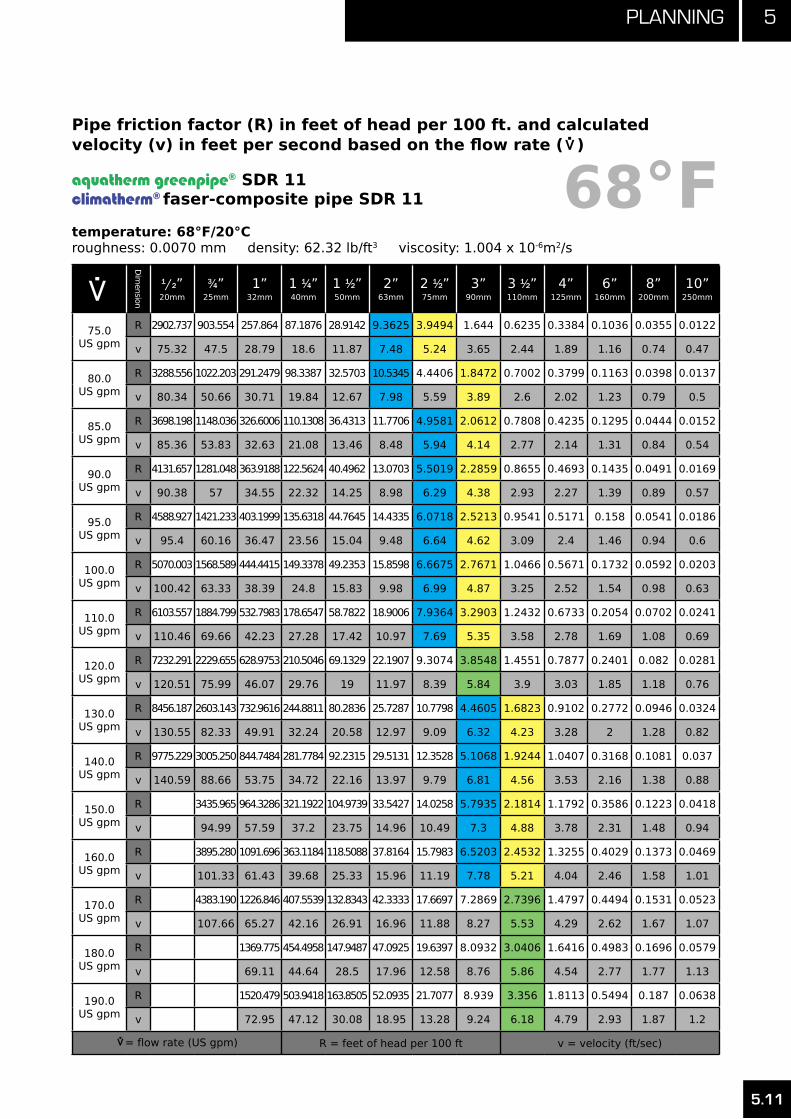
5.11
5Planning
.> Dim
ension
1/2”20mm
3⁄4”25mm
1”32mm
1 1⁄4”40mm
1 1⁄2”50mm
2”63mm
2 1⁄2”75mm
3”90mm
3 1⁄2”110mm
4”125mm
6”160mm
8”200mm
10”250mm
75.0US gpm
R 2902.737 903.554 257.864 87.1876 28.9142 9.3625 3.9494 1.644 0.6235 0.3384 0.1036 0.0355 0.0122
v 75.32 47.5 28.79 18.6 11.87 7.48 5.24 3.65 2.44 1.89 1.16 0.74 0.47
80.0US gpm
R 3288.556 1022.203 291.2479 98.3387 32.5703 10.5345 4.4406 1.8472 0.7002 0.3799 0.1163 0.0398 0.0137
v 80.34 50.66 30.71 19.84 12.67 7.98 5.59 3.89 2.6 2.02 1.23 0.79 0.5
85.0US gpm
R 3698.198 1148.036 326.6006 110.1308 36.4313 11.7706 4.9581 2.0612 0.7808 0.4235 0.1295 0.0444 0.0152
v 85.36 53.83 32.63 21.08 13.46 8.48 5.94 4.14 2.77 2.14 1.31 0.84 0.54
90.0US gpm
R 4131.657 1281.048 363.9188 122.5624 40.4962 13.0703 5.5019 2.2859 0.8655 0.4693 0.1435 0.0491 0.0169
v 90.38 57 34.55 22.32 14.25 8.98 6.29 4.38 2.93 2.27 1.39 0.89 0.57
95.0US gpm
R 4588.927 1421.233 403.1999 135.6318 44.7645 14.4335 6.0718 2.5213 0.9541 0.5171 0.158 0.0541 0.0186
v 95.4 60.16 36.47 23.56 15.04 9.48 6.64 4.62 3.09 2.4 1.46 0.94 0.6
100.0US gpm
R 5070.003 1568.589 444.4415 149.3378 49.2353 15.8598 6.6675 2.7671 1.0466 0.5671 0.1732 0.0592 0.0203
v 100.42 63.33 38.39 24.8 15.83 9.98 6.99 4.87 3.25 2.52 1.54 0.98 0.63
110.0US gpm
R 6103.557 1884.799 532.7983 178.6547 58.7822 18.9006 7.9364 3.2903 1.2432 0.6733 0.2054 0.0702 0.0241
v 110.46 69.66 42.23 27.28 17.42 10.97 7.69 5.35 3.58 2.78 1.69 1.08 0.69
120.0US gpm
R 7232.291 2229.655 628.9753 210.5046 69.1329 22.1907 9.3074 3.8548 1.4551 0.7877 0.2401 0.082 0.0281
v 120.51 75.99 46.07 29.76 19 11.97 8.39 5.84 3.9 3.03 1.85 1.18 0.76
130.0US gpm
R 8456.187 2603.143 732.9616 244.8811 80.2836 25.7287 10.7798 4.4605 1.6823 0.9102 0.2772 0.0946 0.0324
v 130.55 82.33 49.91 32.24 20.58 12.97 9.09 6.32 4.23 3.28 2 1.28 0.82
140.0US gpm
R 9775.229 3005.250 844.7484 281.7784 92.2315 29.5131 12.3528 5.1068 1.9244 1.0407 0.3168 0.1081 0.037
v 140.59 88.66 53.75 34.72 22.16 13.97 9.79 6.81 4.56 3.53 2.16 1.38 0.88
150.0US gpm
R 3435.965 964.3286 321.1922 104.9739 33.5427 14.0258 5.7935 2.1814 1.1792 0.3586 0.1223 0.0418
v 94.99 57.59 37.2 23.75 14.96 10.49 7.3 4.88 3.78 2.31 1.48 0.94
160.0US gpm
R 3895.280 1091.696 363.1184 118.5088 37.8164 15.7983 6.5203 2.4532 1.3255 0.4029 0.1373 0.0469
v 101.33 61.43 39.68 25.33 15.96 11.19 7.78 5.21 4.04 2.46 1.58 1.01
170.0US gpm
R 4383.190 1226.846 407.5539 132.8343 42.3333 17.6697 7.2869 2.7396 1.4797 0.4494 0.1531 0.0523
v 107.66 65.27 42.16 26.91 16.96 11.88 8.27 5.53 4.29 2.62 1.67 1.07
180.0US gpm
R 1369.775 454.4958 147.9487 47.0925 19.6397 8.0932 3.0406 1.6416 0.4983 0.1696 0.0579
v 69.11 44.64 28.5 17.96 12.58 8.76 5.86 4.54 2.77 1.77 1.13
190.0US gpm
R 1520.479 503.9418 163.8505 52.0935 21.7077 8.939 3.356 1.8113 0.5494 0.187 0.0638
v 72.95 47.12 30.08 18.95 13.28 9.24 6.18 4.79 2.93 1.87 1.2
.>
= flow rate (US gpm) R = feet of head per 100 ft v = velocity (ft/sec)
68°FPipe friction factor (R) in feet of head per 100 ft. and calculated velocity (v) in feet per second based on the flow rate (
.>
)
aquatherm greenpipe® SDR 11climatherm® faser-composite pipe SDR 11
temperature: 68°F/20°Croughness: 0.0070 mm density: 62.32 lb/ft3 viscosity: 1.004 x 10⁻⁶m2/s
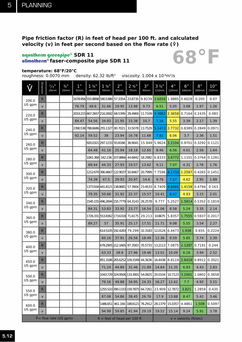
5 Planning
5.12
.> Dim
ension
1/2”20mm
3⁄4”25mm
1”32mm
1 1⁄4”40mm
1 1⁄2”50mm
2”63mm
2 1⁄2”75mm
3”90mm
3 1⁄2”110mm
4”125mm
6”160mm
8”200mm
10”250mm
200.0US gpm
R 1678.956 555.8898 180.5386 57.3354 23.8735 9.8239 3.6858 1.9885 0.6028 0.205 0.07
v 76.79 49.6 31.66 19.95 13.98 9.73 6.51 5.05 3.08 1.97 1.26
220.0US gpm
R 2019.215 667.2847 216.2692 68.5399 28.4969 11.7109 4.3882 2.3658 0.7164 0.2435 0.083
v 84.47 54.56 34.83 21.95 15.38 10.7 7.16 5.55 3.39 2.17 1.39
240.0US gpm
R 2390.538 788.6686 255.1327 80.7021 33.5078 13.7529 5.1472 2.7732 0.8389 0.2849 0.0971
v 92.14 59.52 38 23.94 16.78 11.68 7.81 6.06 3.7 2.36 1.51
260.0US gpm
R 920.0321 297.1233 93.8186 38.9041 15.949 5.9624 3.2104 0.9701 0.3292 0.1121
v 64.48 41.16 25.94 18.18 12.65 8.46 6.56 4.01 2.56 1.64
280.0US gpm
R 1061.368 342.236 107.8866 44.6842 18.2982 6.8333 3.6772 1.1101 0.3764 0.1281
v 69.44 44.33 27.93 19.57 13.62 9.11 7.07 4.31 2.76 1.76
300.0US gpm
R 1212.670 390.4667 122.9037 50.8467 20.7999 7.7596 4.1733 1.2587 0.4265 0.1451
v 74.39 47.5 29.93 20.97 14.6 9.76 7.57 4.62 2.95 1.89
320.0US gpm
R 1373.934 441.8121 138.8681 57.3904 23.4533 8.7409 4.6985 1.4158 0.4794 0.163
v 79.35 50.66 31.92 22.37 15.57 10.41 8.07 4.93 3.15 2.01
340.0US gpm
R 1545.155 496.2694 155.7779 64.3143 26.2578 9.777 5.2527 1.5814 0.5352 0.1819
v 84.31 53.83 33.92 23.77 16.54 11.06 8.58 5.24 3.35 2.14
360.0US gpm
R 1726.331 553.8362 173.6318 71.6175 29.213 10.8675 5.8357 1.7555 0.5937 0.2017
v 89.27 57 35.91 25.17 17.51 11.71 9.08 5.55 3.54 2.27
380.0US gpm
R 614.5105 192.4283 79.299 32.3183 12.0124 6.4473 1.938 0.655 0.2224
v 60.16 37.91 26.56 18.49 12.36 9.59 5.85 3.74 2.39
400.0US gpm
R 678.2905 212.1665 87.3583 35.5733 13.2113 7.0875 2.1287 0.7191 0.244
v 63.33 39.9 27.96 19.46 13.01 10.09 6.16 3.94 2.52
450.0US gpm
R 851.3186 265.6252 109.1549 44.3636 16.4438 8.8119 2.6418 0.8912 0.3021
v 71.24 44.89 31.46 21.89 14.64 11.35 6.93 4.43 2.83
500.0US gpm
R 1043.729 324.9506 133.3001 54.0825 20.0104 10.7123 3.2061 1.0802 0.3658
v 79.16 49.88 34.95 24.33 16.27 12.62 7.7 4.92 3.15
550.0US gpm
R 1255.510 390.1333 159.7875 64.7261 23.909 12.7872 3.821 1.2859 0.435
v 87.08 54.86 38.45 26.76 17.9 13.88 8.47 5.42 3.46
600.0US gpm
R 1486.651 461.166 188.6121 76.2912 28.1379 15.0357 4.4861 1.508 0.5097
v 94.99 59.85 41.94 29.19 19.52 15.14 9.24 5.91 3.78
.>
= flow rate (US gpm) R = feet of head per 100 ft v = velocity (ft/sec)
68°FPipe friction factor (R) in feet of head per 100 ft. and calculated velocity (v) in feet per second based on the flow rate (
.>
)
aquatherm greenpipe® SDR 11climatherm® faser-composite pipe SDR 11
temperature: 68°F/20°Croughness: 0.0070 mm density: 62.32 lb/ft3 viscosity: 1.004 x 10⁻⁶m2/s

5.13
5Planning
.> Dim
ension
1/2”20mm
3⁄4”25mm
1”32mm
1 1⁄4”40mm
1 1⁄2”50mm
2”63mm
2 1⁄2”75mm
3”90mm
3 1⁄2”110mm
4”125mm
6”160mm
8”200mm
10”250mm
650.0US gpm
R 1737.143 538.0432 219.7699 88.7752 32.6957 17.4566 5.2011 1.7465 0.5898
v 102.91 64.84 45.44 31.62 21.15 16.4 10.01 6.4 4.09
700.0US gpm
R 2006.982 620.7603 253.2576 102.176 37.5812 20.0493 5.9655 2.0012 0.6752
v 110.82 69.83 48.93 34.06 22.78 17.66 10.78 6.89 4.41
750.0US gpm
R 2296.162 709.3139 289.0726 116.4917 42.7932 22.813 6.7791 2.2719 0.766
v 118.74 74.82 52.43 36.49 24.4 18.92 11.55 7.39 4.72
800.0US gpm
R 2604.680 803.7009 327.2127 131.721 48.331 25.7471 7.6417 2.5586 0.862
v 126.66 79.8 55.93 38.92 26.03 20.19 12.32 7.88 5.04
850.0US gpm
R 2932.533 903.919 367.676 147.8624 54.1938 28.8511 8.5529 2.8612 0.9633
v 134.57 84.79 59.42 41.35 27.66 21.45 13.09 8.37 5.35
900.0US gpm
R 1009.966 410.461 164.915 60.3809 32.1245 9.5127 3.1796 1.0697
v 89.78 62.92 43.79 29.28 22.71 13.86 8.86 5.67
950.0US gpm
R 1121.840 455.5663 182.8777 66.8916 35.567 10.5208 3.5136 1.1813
v 94.77 66.41 46.22 30.91 23.97 14.63 9.35 5.98
1000.0US gpm
R 1239.541 502.9909 201.7497 73.7256 39.1781 11.5771 3.8633 1.298
v 99.75 69.91 48.65 32.54 25.23 15.4 9.85 6.3
1050.0US gpm
R 1363.066 552.7336 221.5304 80.8822 42.9576 12.6814 4.2286 1.4198
v 104.74 73.4 51.08 34.16 26.49 16.17 10.34 6.61
1100.0US gpm
R 1492.415 604.7938 242.219 88.3612 46.9051 13.8335 4.6093 1.5467
v 109.73 76.9 53.52 35.79 27.76 16.94 10.83 6.93
1150.0US gpm
R 1627.587 659.1706 263.815 96.1621 51.0203 15.0335 5.0055 1.6786
v 114.72 80.39 55.95 37.42 29.02 17.71 11.32 7.24
1200.0US gpm
R 1768.582 715.8634 286.3179 104.2847 55.3032 16.281 5.4171 1.8156
v 119.71 83.89 58.38 39.04 30.28 18.49 11.82 7.55
1250.0US gpm
R 1915.397 774.8717 309.7274 112.7286 59.7533 17.5761 5.844 1.9576
v 124.69 87.38 60.82 40.67 31.54 19.26 12.31 7.87
1300.0US gpm
R 2068.033 836.1948 334.0429 121.4936 64.3705 18.9186 6.2863 2.1045
v 129.68 90.88 63.25 42.3 32.8 20.03 12.8 8.18
1350.0US gpm
R 2226.490 899.8325 359.2641 130.5793 69.1547 20.3085 6.7438 2.2565
v 134.67 94.37 65.68 43.92 34.06 20.8 13.29 8.5
.>
= flow rate (US gpm) R = feet of head per 100 ft v = velocity (ft/sec)
68°FPipe friction factor (R) in feet of head per 100 ft. and calculated velocity (v) in feet per second based on the flow rate (
.>
)
aquatherm greenpipe® SDR 11climatherm® faser-composite pipe SDR 11
temperature: 68°F/20°Croughness: 0.0070 mm density: 62.32 lb/ft3 viscosity: 1.004 x 10⁻⁶m2/s

5 Planning
5.14
.> Dim
ension
1/2”20mm
3⁄4”25mm
1”32mm
1 1⁄4”40mm
1 1⁄2”50mm
2”63mm
2 1⁄2”75mm
3”90mm
3 1⁄2”110mm
4”125mm
6”160mm
8”200mm
10”250mm
1400.0US gpm
R 2390.767 965.7843 385.3908 139.9857 74.1057 21.7456 7.2165 2.4134
v 139.66 97.87 68.11 45.55 35.33 21.57 13.79 8.81
1450.0US gpm
R 2560.863 1034.049 412.4226 149.7125 79.2233 23.2299 7.7044 2.5752
v 144.64 101.37 70.55 47.18 36.59 22.34 14.28 9.13
1500.0US gpm
R 2736.778 1104.628 440.3593 159.7595 84.5074 24.7613 8.2074 2.742
v 149.63 104.86 72.98 48.8 37.85 23.11 14.77 9.44
1550.0US gpm
R 1177.520 469.2007 170.1265 89.9579 26.3398 8.7256 2.9136
v 108.36 75.41 50.43 39.11 23.88 15.26 9.76
1600.0US gpm
R 1252.725 498.9465 180.8135 95.5746 27.9653 9.2588 3.0902
v 111.85 77.84 52.06 40.37 24.65 15.75 10.07
1650.0US gpm
R 1330.243 529.5965 191.8202 101.3575 29.6377 9.8072 3.2716
v 115.35 80.28 53.69 41.63 25.42 16.25 10.39
.>
= flow rate (US gpm) R = feet of head per 100 ft v = velocity (ft/sec)
68°FPipe friction factor (R) in feet of head per 100 ft. and calculated velocity (v) in feet per second based on the flow rate (
.>
)
aquatherm greenpipe® SDR 11climatherm® faser-composite pipe SDR 11
temperature: 68°F/20°Croughness: 0.0070 mm density: 62.32 lb/ft3 viscosity: 1.004 x 10⁻⁶m2/s

5.15
5Planning
.> Dim
ension
3⁄8”16mm
1/2”20mm
3⁄4”25mm
1”32mm
1 1⁄4”40mm
1 1⁄2”50mm
2”63mm
2 1⁄2”75mm
3”90mm
3 1⁄2”110mm
4”125mm
6”160mm
8”200mm
10”250mm
0.1US gpm
R 0.1126 0.0415 0.0148 0.0046 0.0017 0.0006 0.0002 0.0001 0 0 0 0 0 0
v 0.2 0.13 0.08 0.05 0.03 0.02 0.01 0.01 0.01 0 0 0 0 0
0.2US gpm
R 0.3523 0.1285 0.0455 0.014 0.005 0.0018 0.0006 0.0003 0.0001 0 0 0 0 0
v 0.39 0.25 0.16 0.1 0.06 0.04 0.03 0.02 0.01 0.01 0.01 0 0 0
0.3US gpm
R 0.6947 0.2522 0.0889 0.0273 0.0097 0.0035 0.0012 0.0005 0.0002 0.0001 0.0001 0 0 0
v 0.59 0.38 0.24 0.15 0.09 0.06 0.04 0.03 0.02 0.01 0.01 0.01 0 0
0.4US gpm
R 1.13 0.4088 0.1436 0.0439 0.0155 0.0055 0.0019 0.0008 0.0004 0.0001 0.0001 0 0 0
v 0.78 0.51 0.33 0.2 0.13 0.08 0.05 0.04 0.02 0.02 0.01 0.01 0.01 0
0.5US gpm
R 1.6524 0.5963 0.209 0.0637 0.0225 0.008 0.0027 0.0012 0.0005 0.0002 0.0001 0 0 0
v 0.98 0.64 0.41 0.24 0.16 0.1 0.06 0.04 0.03 0.02 0.02 0.01 0.01 0
0.6US gpm
R 2.258 0.8131 0.2844 0.0864 0.0304 0.0108 0.0036 0.0016 0.0007 0.0003 0.0002 0 0 0
v 1.18 0.76 0.49 0.29 0.19 0.12 0.08 0.05 0.04 0.02 0.02 0.01 0.01 0
0.7US gpm
R 2.9435 1.0581 0.3694 0.112 0.0394 0.014 0.0047 0.0021 0.0009 0.0004 0.0002 0.0001 0 0
v 1.37 0.89 0.57 0.34 0.22 0.14 0.09 0.06 0.04 0.03 0.02 0.01 0.01 0.01
0.8US gpm
R 3.7067 1.3304 0.4638 0.1404 0.0493 0.0174 0.0058 0.0026 0.0011 0.0004 0.0002 0.0001 0 0
v 1.57 1.02 0.65 0.39 0.25 0.16 0.1 0.07 0.05 0.03 0.03 0.02 0.01 0.01
0.9US gpm
R 4.5456 1.6291 0.5672 0.1715 0.0601 0.0213 0.0071 0.0032 0.0013 0.0005 0.0003 0.0001 0 0
v 1.76 1.14 0.73 0.44 0.28 0.18 0.11 0.08 0.06 0.04 0.03 0.02 0.01 0.01
1.0US gpm
R 5.4585 1.9538 0.6794 0.2052 0.0718 0.0254 0.0084 0.0038 0.0016 0.0006 0.0003 0.0001 0 0
v 1.96 1.27 0.81 0.49 0.31 0.2 0.13 0.09 0.06 0.04 0.03 0.02 0.01 0.01
2.0US gpm
R 18.4253 6.5356 2.2538 0.6748 0.2346 0.0823 0.0272 0.0121 0.0051 0.0020 0.0011 0.0003 0.0001 0.0000
v 3.9200 2.5400 1.6300 0.9800 0.6300 0.4000 0.2500 0.1800 0.1200 0.0800 0.0600 0.0400 0.0300 0.0200
3.0US gpm
R 37.9310 13.3728 4.5870 1.3662 0.4729 0.1653 0.0543 0.0241 0.0101 0.0040 0.0022 0.0007 0.0002 0.0001
v 5.8800 3.8100 2.4400 1.4700 0.9400 0.6000 0.3800 0.2700 0.1800 0.1200 0.1000 0.0600 0.0400 0.0200
4.0US gpm
R 63.6256 22.3244 7.6256 2.2622 0.7806 0.2721 0.0892 0.0395 0.0166 0.0065 0.0035 0.0011 0.0004 0.0001
v 7.8300 5.0800 3.2500 1.9600 1.2500 0.8000 0.5000 0.3600 0.2500 0.1700 0.1300 0.0800 0.0500 0.0300
5.0US gpm
R 95.32 33.31 11.34 3.35 1.15 0.40 0.13 0.06 0.02 0.01 0.01 0.00 0.00 0.00
v 9.79 6.35 4.07 2.45 1.57 1.01 0.63 0.45 0.31 0.21 0.16 0.10 0.06 0.04
6.0US gpm
R 132.88 46.27 15.70 4.63 1.59 0.55 0.18 0.08 0.03 0.01 0.01 0.00 0.00 0.00
v 11.75 7.63 4.88 2.94 1.88 1.21 0.75 0.53 0.37 0.25 0.19 0.12 0.08 0.05
.>
= flow rate (US gpm) R = feet of head per 100 ft v = velocity (ft/sec)
Pipe friction factor (R) in feet of head per 100 ft. and calculated velocity (v) in feet per second based on the flow rate (
.>
)
aquatherm greenpipe® faser-composite pipe SDR 7.4
temperature: 68°F/20°Croughness: 0.0070 mm density: 62.32 lb/ft3 viscosity: 1.004 x 10⁻⁶m2/s
68°F

5 Planning
5.16
.> Dim
ension
3⁄8”16mm
1/2”20mm
3⁄4”25mm
1”32mm
1 1⁄4”40mm
1 1⁄2”50mm
2”63mm
2 1⁄2”75mm
3”90mm
3 1⁄2”110mm
4”125mm
6”160mm
8”200mm
10”250mm
7.0US gpm
R 176.23 61.18 20.71 6.09 2.09 0.72 0.24 0.10 0.04 0.02 0.01 0.00 0.00 0.00
v 13.71 8.90 5.69 3.43 2.19 1.41 0.88 0.62 0.43 0.29 0.22 0.14 0.09 0.06
8.0US gpm
R 225.30 78.00 26.33 7.73 2.64 0.92 0.30 0.13 0.05 0.02 0.01 0.00 0.00 0.00
v 15.67 10.17 6.51 3.92 2.51 1.61 1.01 0.71 0.49 0.33 0.26 0.16 0.10 0.06
9.0US gpm
R 280.06 96.71 32.58 9.54 3.26 1.13 0.37 0.16 0.07 0.03 0.01 0.00 0.00 0.00
v 17.63 11.44 7.32 4.41 2.82 1.81 1.13 0.80 0.55 0.37 0.29 0.18 0.11 0.07
10.0US gpm
R 340.45 117.30 39.43 11.52 3.93 1.36 0.44 0.19 0.08 0.03 0.02 0.01 0.00 0.00
v 19.59 12.71 8.13 4.90 3.13 2.01 1.26 0.89 0.62 0.41 0.32 0.20 0.13 0.08
11.0US gpm
R 406.46 139.74 46.89 13.68 4.66 1.61 0.52 0.23 0.10 0.04 0.02 0.01 0.00 0.00
v 21.54 13.98 8.95 5.39 3.45 2.21 1.38 0.98 0.68 0.46 0.35 0.21 0.14 0.09
12US gpm
R 478.07 164.04 54.94 16.00 5.45 1.88 0.61 0.27 0.11 0.04 0.02 0.01 0.00 0.00
v 23.50 15.25 9.76 5.88 3.76 2.41 1.51 1.07 0.74 0.50 0.38 0.23 0.15 0.10
13.0US gpm
R 555.24 190.17 63.58 18.48 6.28 2.16 0.70 0.31 0.13 0.05 0.03 0.01 0.00 0.00
v 25.46 16.52 10.57 6.37 4.07 2.61 1.63 1.16 0.80 0.54 0.42 0.25 0.16 0.11
14.0US gpm
R 637.98 218.13 72.81 21.14 7.18 2.47 0.80 0.35 0.15 0.06 0.03 0.01 0.00 0.00
v 27.42 17.79 11.39 6.86 4.39 2.82 1.76 1.25 0.86 0.58 0.45 0.27 0.18 0.11
15.0US gpm
R 726.25 247.92 82.63 23.95 8.12 2.79 0.90 0.40 0.16 0.06 0.03 0.01 0.00 0.00
v 29.38 19.06 12.20 7.34 4.70 3.02 1.88 1.34 0.92 0.62 0.48 0.29 0.19 0.12
16.0US gpm
R 820.07 279.52 93.03 26.93 9.13 3.13 1.01 0.44 0.18 0.07 0.04 0.01 0.00 0.00
v 31.34 20.34 13.01 7.83 5.01 3.22 2.01 1.42 0.99 0.66 0.51 0.31 0.20 0.13
17.0US gpm
R 919.40 312.93 104.01 30.06 10.18 3.49 1.13 0.49 0.21 0.08 0.04 0.01 0.00 0.00
v 33.30 21.61 13.83 8.32 5.33 3.42 2.14 1.51 1.05 0.70 0.54 0.33 0.21 0.14
18.0US gpm
R 1024.25 348.15 115.57 33.36 11.28 3.87 1.25 0.55 0.23 0.09 0.05 0.01 0.01 0.00
v 35.25 22.88 14.64 8.81 5.64 3.62 2.26 1.60 1.11 0.74 0.58 0.35 0.23 0.15
19.0US gpm
R 1134.61 385.17 127.70 36.82 12.44 4.26 1.37 0.60 0.25 0.10 0.05 0.02 0.01 0.00
v 37.21 24.15 15.45 9.30 5.95 3.82 2.39 1.69 1.17 0.79 0.61 0.37 0.24 0.15
20.0US gpm
R 1250.48 423.99 140.40 40.43 13.65 4.67 1.51 0.66 0.27 0.11 0.06 0.02 0.01 0.00
v 39.17 25.42 16.27 9.79 6.27 4.02 2.51 1.78 1.23 0.83 0.64 0.39 0.25 0.16
22.0US gpm
R 1498.69 507.02 167.52 48.14 16.23 5.54 1.79 0.78 0.32 0.13 0.07 0.02 0.01 0.00
v 43.09 27.96 17.90 10.77 6.89 4.42 2.76 1.96 1.36 0.91 0.70 0.43 0.28 0.18
.>
= flow rate (US gpm) R = feet of head per 100 ft v = velocity (ft/sec)
Pipe friction factor (R) in feet of head per 100 ft. and calculated velocity (v) in feet per second based on the flow rate (
.>
)
aquatherm greenpipe® faser-composite pipe SDR 7.4
temperature: 68°F/20°Croughness: 0.0070 mm density: 62.32 lb/ft3 viscosity: 1.004 x 10⁻⁶m2/s
68°F

5.17
5Planning
.> Dim
ension
3⁄8”16mm
1/2”20mm
3⁄4”25mm
1”32mm
1 1⁄4”40mm
1 1⁄2”50mm
2”63mm
2 1⁄2”75mm
3”90mm
3 1⁄2”110mm
4”125mm
6”160mm
8”200mm
10”250mm
24.0US gpm
R 1768.86 597.21 196.92 56.46 19.00 6.49 2.09 0.91 0.38 0.15 0.08 0.02 0.01 0.00
v 47.01 30.50 19.52 11.75 7.52 4.83 3.02 2.14 1.48 0.99 0.77 0.47 0.30 0.19
26.0US gpm
R 2060.96 694.54 228.58 65.41 21.98 7.49 2.41 1.05 0.44 0.17 0.09 0.03 0.01 0.00
v 50.92 33.05 21.15 12.73 8.15 5.23 3.27 2.32 1.60 1.08 0.83 0.51 0.33 0.21
28.0US gpm
R 2374.96 799.00 262.50 74.98 25.16 8.57 2.75 1.20 0.50 0.19 0.10 0.03 0.01 0.00
v 54.84 35.59 22.78 13.71 8.77 5.63 3.52 2.49 1.73 1.16 0.90 0.55 0.35 0.23
30.0US gpm
R 2710.86 910.58 298.67 85.17 28.54 9.71 3.11 1.36 0.56 0.22 0.12 0.04 0.01 0.00
v 58.76 38.13 24.40 14.69 9.40 6.03 3.77 2.67 1.85 1.24 0.96 0.59 0.38 0.24
32.0US gpm
R 3068.62 1029.27 337.09 95.96 32.12 10.91 3.50 1.53 0.63 0.24 0.13 0.04 0.01 0.01
v 62.67 40.67 26.03 15.67 10.03 6.44 4.02 2.85 1.97 1.32 1.02 0.62 0.40 0.26
34.0US gpm
R 3448.25 1155.06 377.74 107.37 35.90 12.18 3.90 1.70 0.70 0.27 0.15 0.04 0.02 0.01
v 66.59 43.21 27.66 16.65 10.65 6.84 4.27 3.03 2.09 1.41 1.09 0.66 0.43 0.28
36.0US gpm
R 3849.74 1287.95 420.63 119.39 39.87 13.52 4.32 1.88 0.78 0.30 0.16 0.05 0.02 0.01
v 70.51 45.75 29.28 17.63 11.28 7.24 4.52 3.21 2.22 1.49 1.15 0.70 0.45 0.29
38.0US gpm
R 4273.06 1427.92 465.75 132.01 44.04 14.91 4.77 2.08 0.86 0.33 0.18 0.05 0.02 0.01
v 74.43 48.30 30.91 18.61 11.91 7.64 4.77 3.38 2.34 1.57 1.21 0.74 0.48 0.31
40.0US gpm
R 4718.22 1574.97 513.10 145.24 48.40 16.38 5.23 2.28 0.94 0.36 0.19 0.06 0.02 0.01
v 78.34 50.84 32.54 19.59 12.53 8.04 5.03 3.56 2.46 1.66 1.28 0.78 0.50 0.32
45.0US gpm
R 5926.62 1973.56 641.21 180.94 60.14 20.31 6.47 2.82 1.16 0.45 0.24 0.07 0.03 0.01
v 88.14 57.19 36.60 22.03 14.10 9.05 5.65 4.01 2.77 1.86 1.44 0.88 0.56 0.30
50US gpm
R 7271.379 2416.316 783.190 220.390 73.0923 24.6322 7.8355 3.4047 1.3999 0.5375 0.2892 0.0888 0.0306 0.0109
v 97.93 63.55 40.67 24.48 15.67 10.06 6.28 4.45 3.08 2.07 1.6 0.98 0.63 0.4
55US gpm
R
2903.213 939.0158 263.5802 87.2342 29.3441 9.3191 4.0452 1.6618 0.6375 0.3429 0.1052 0.0363 0.0129
v
69.90 44.74 26.93 17.24 11.06 6.91 4.9 3.39 2.28 1.76 1.07 0.69 0.45
60.0US gpm
R
3434.214 1108.664 310.4936 102.5631 34.4414 10.921 4.7361 1.9439 0.7451 0.4006 0.1228 0.0423 0.015
v
76.26 48.8 29.38 18.8 12.07 7.54 5.34 3.7 2.48 1.92 1.17 0.75 0.49
65.0US gpm
R
4009.295 1292.119 361.1212 119.0738 39.9216 12.6403 5.4767 2.246 0.8603 0.4623 0.1416 0.0487 0.0173
v
82.61 52.87 31.83 20.37 13.07 8.17 5.79 4.01 2.69 2.08 1.27 0.81 0.53
70.0US gpm
R
4628.439 1489.367 415.4549 136.7618 45.7824 14.476 6.2667 2.568 0.9829 0.5279 0.1616 0.0556 0.0197
v
88.97 56.94 34.28 21.94 14.08 8.79 6.23 4.31 2.9 2.24 1.37 0.88 0.57
.>
= flow rate (US gpm) R = feet of head per 100 ft v = velocity (ft/sec)
Pipe friction factor (R) in feet of head per 100 ft. and calculated velocity (v) in feet per second based on the flow rate (
.>
)
aquatherm greenpipe® faser-composite pipe SDR 7.4
temperature: 68°F/20°Croughness: 0.0070 mm density: 62.32 lb/ft3 viscosity: 1.004 x 10⁻⁶m2/s
68°F

5 Planning
5.18
.> Dim
ension
3⁄8”16mm
1/2”20mm
3⁄4”25mm
1”32mm
1 1⁄4”40mm
1 1⁄2”50mm
2”63mm
2 1⁄2”75mm
3”90mm
3 1⁄2”110mm
4”125mm
6”160mm
8”200mm
10”250mm
75.0US gpm
R
5291.630 1700.396 473.4878 155.6236 52.0222 16.4273 7.1056 2.9095 1.1129 0.5975 0.1827 0.0628 0.0223
v
95.32 61.01 36.72 23.5 15.08 9.42 6.68 4.62 3.1 2.4 1.46 0.94 0.61
80.0US gpm
R
5998.857 1925.198 535.2145 175.6557 58.6392 18.4936 7.9931 3.2706 1.2501 0.671 0.2051 0.0705 0.025
v
101.68 65.07 39.17 25.07 16.09 10.05 7.12 4.93 3.31 2.56 1.56 1 0.65
85.0US gpm
R
6750.111 2163.766 600.6301 196.8555 65.632 20.6742 8.9288 3.6509 1.3946 0.7483 0.2285 0.0785 0.0278
v
108.03 69.14 41.62 26.64 17.09 10.68 7.57 5.24 3.52 2.72 1.66 1.06 0.69
90.0US gpm
R
7545.383 2416.093 669.7305 219.2205 72.9994 22.9685 9.9126 4.0505 1.5463 0.8293 0.2532 0.0869 0.0308
v
114.39 73.21 44.07 28.2 18.1 11.31 8.01 5.55 3.72 2.88 1.76 1.13 0.73
95.0US gpm
R
8384.667 2682.173 742.5123 242.7487 80.7403 25.3762 10.944 4.4691 1.7051 0.9142 0.2789 0.0958 0.0339
v
120.74 77.27 46.52 29.77 19.11 11.94 8.46 5.85 3.93 3.04 1.85 1.19 0.77
100.0US gpm
R
9267.958 2962.003 818.9724 267.4382 88.8536 27.8966 12.0229 4.9066 1.871 1.0028 0.3058 0.1049 0.0371
v
127.10 81.34 48.96 31.34 20.11 12.56 8.91 6.16 4.14 3.2 1.95 1.25 0.81
110.0US gpm
R
11166.54 3562.897 982.9173 320.2946 106.1942 33.2743 14.3223 5.8381 2.2238 1.1912 0.3629 0.1244 0.044
v
139.81 89.48 53.86 34.47 22.12 13.82 9.8 6.78 4.55 3.52 2.15 1.38 0.89
120.0US gpm
R
13241.11 4218.750 1161.548 377.7787 125.0151 39.0987 16.8091 6.8441 2.6043 1.3942 0.4243 0.1454 0.0513
v
152.52 97.61 58.76 37.6 24.13 15.08 10.69 7.39 4.97 3.84 2.34 1.5 0.97
130.0US gpm
R
15491.63 4929.542 1354.850 439.8816 145.311 45.3674 19.4821 7.9241 3.0123 1.6118 0.4901 0.1678 0.0592
v
165.23 105.74 63.65 40.74 26.14 16.33 11.58 8.01 5.38 4.16 2.54 1.63 1.05
140.0US gpm
R
17918.10 5695.261 1562.815 506.5962 167.078 52.0783 22.3401 9.0775 3.4476 1.8437 0.5601 0.1917 0.0676
v
177.93 113.88 68.55 43.87 28.16 17.59 12.47 8.63 5.79 4.48 2.73 1.75 1.13
150US gpm
R
6515.895 1785.432 577.9166 190.3124 59.2298 25.3821 10.3037 3.9098 2.0899 0.6344 0.217 0.0765
v
122.01 73.45 47.01 30.17 18.85 13.36 9.24 6.21 4.79 2.93 1.88 1.21
160.0US gpm
R
7391.435 2022.695 653.8378 215.0113 66.8201 28.6073 11.6023 4.3989 2.3502 0.7129 0.2437 0.0859
v
130.15 78.34 50.14 32.18 20.1 14.25 9.86 6.62 5.11 3.12 2 1.3
170.0US gpm
R
8321.874 2274.598 734.3557 241.172 74.848 32.0149 12.973 4.9146 2.6245 0.7955 0.2718 0.0957
v
138.28 83.24 53.27 34.19 21.36 15.14 10.47 7.04 5.43 3.32 2.13 1.38
180US gpm
R
2541.137 819.4668 268.7924 83.3124 35.6042 14.4153 5.4567 2.9127 0.8823 0.3012 0.106
v
88.1456.41 36.2 22.62 16.03 11.09 7.45 5.75 3.51 2.25 1.46
190.0US gpm
R
2822.307 909.1682 297.8706 92.2121 39.3746 15.929 6.0252 3.2148 0.9731 0.3321 0.1169
v
93.03 59.54 38.21 23.87 16.92 11.71 7.86 6.07 3.71 2.38 1.54
.>
= flow rate (US gpm) R = feet of head per 100 ft v = velocity (ft/sec)
Pipe friction factor (R) in feet of head per 100 ft. and calculated velocity (v) in feet per second based on the flow rate (
.>
)
aquatherm greenpipe® faser-composite pipe SDR 7.4
temperature: 68°F/20°Croughness: 0.0070 mm density: 62.32 lb/ft3 viscosity: 1.004 x 10⁻⁶m2/s
68°F

5.19
5Planning
.> Dim
ension
3⁄8”16mm
1/2”20mm
3⁄4”25mm
1”32mm
1 1⁄4”40mm
1 1⁄2”50mm
2”63mm
2 1⁄2”75mm
3”90mm
3 1⁄2”110mm
4”125mm
6”160mm
8”200mm
10”250mm
200US gpm
R
3118.105 1003.457 328.4048 101.5462 43.3255 17.5138 6.6198 3.5306 1.068 0.3643 0.1281
v
97.93 62.67 40.22 25.13 17.81 12.32 8.28 6.39 3.9 2.5 1.62
220.0US gpm
R
3753.574 1205.790 393.8358 121.5146 51.7672 20.8955 7.8871 4.2032 1.2698 0.4327 0.1521
v
107.72 68.94 44.24 27.64 19.59 13.56 9.1 7.03 4.29 2.75 1.78
240.0
US gpm
R
4447.527 1426.451 465.0755 143.2119 60.9257 24.5586 9.2577 4.93 1.4876 0.5065 0.1779
v
117.51 75.21 48.27 30.15 21.37 14.79 9.93 7.67 4.68 3 1.94
260US gpm
R
1665.430 542.1163 166.6336 70.7983 28.5015 10.7309 5.7105 1.7212 0.5855 0.2055
v
81.48 52.29 32.67 23.15 16.02 10.76 8.31 5.07 3.25 2.11
280.0US gpm
R
1922.717 624.952 191.7759 81.3825 32.723 12.3059 6.5444 1.9703 0.6697 0.2349
v
87.74 56.31 35.18 24.94 17.25 11.59 8.95 5.47 3.5 2.27
300.0US gpm
R
2198.306 713.5774 218.6357 92.6765 37.2218 13.9823 7.4312 2.235 0.7591 0.2661
v
94.01 60.33 37.69 26.72 18.49 12.42 9.59 5.86 3.75 2.43
320.0US gpm
R
2492.191 807.9885 247.2103 104.6785 41.9969 15.7596 8.3706 2.5151 0.8536 0.2991
v
100.28 64.36 40.2 28.5 19.72 13.24 10.23 6.25 4 2.59
340.0US gpm
R
2804.368 908.1818 277.4975 117.387 47.0476 17.6372 9.3624 2.8104 0.9532 0.3338
v
106.55 68.38 42.72 30.28 20.95 14.07 10.87 6.64 4.25 2.75
360.0US gpm
R
3134.833 1014.154 309.4954 130.8007 52.373 19.6147 10.4064 3.1209 1.0578 0.3702
v
112.81 72.4 45.23 32.06 22.18 14.9 11.51 7.03 4.5 2.92
380US gpm
R
1125.904 343.2024 144.9185 57.9725 21.6919 11.5023 3.4465 1.1674 0.4083
v
76.42 47.74 33.84 23.41 15.73 12.15 7.42 4.75 3.08
400.0US gpm
R
1243.428 378.6169 159.7394 63.8454 23.8684 12.6498 3.7871 1.2819 0.4482
v
80.45 50.26 35.62 24.65 16.55 12.79 7.81 5 3.24
450.0US gpm
R
1562.493 474.6165 199.8625 79.7208 29.7423 15.7437 4.7038 1.5899 0.5552
v
90.50 56.54 40.07 27.73 18.62 14.38 8.78 5.63 3.64
500.0US gpm
R
1917.619 581.2658 244.364 97.2952 36.2311 19.157 5.7129 1.9283 0.6726
v
100.56 62.82 44.53 30.81 20.69 15.98 9.76 6.25 4.05
550.0US gpm
R
2308.791 698.5533 293.2354 116.563 43.3319 22.8878 6.8136 2.2968 0.8003
v
110.61 69.1 48.98 33.89 22.76 17.58 10.74 6.88 4.45
600.0US gpm
R
2735.996 826.4704 346.4703 137.52 51.0422 26.9344 8.0051 2.6951 0.9381
v
120.67 75.38 53.43 36.97 24.83 19.18 11.71 7.5 4.86
.>
= flow rate (US gpm) R = feet of head per 100 ft v = velocity (ft/sec)
Pipe friction factor (R) in feet of head per 100 ft. and calculated velocity (v) in feet per second based on the flow rate (
.>
)
aquatherm greenpipe® faser-composite pipe SDR 7.4
temperature: 68°F/20°Croughness: 0.0070 mm density: 62.32 lb/ft3 viscosity: 1.004 x 10⁻⁶m2/s
68°F

5 Planning
5.20
.> Dim
ension
3⁄8”16mm
1/2”20mm
3⁄4”25mm
1”32mm
1 1⁄4”40mm
1 1⁄2”50mm
2”63mm
2 1⁄2”75mm
3”90mm
3 1⁄2”110mm
4”125mm
6”160mm
8”200mm
10”250mm
650.0US gpm
R
3199.227 965.0104 404.0636 160.1627 59.3598 31.2954 9.2868 3.123 1.086
v
130.72 81.67 57.89 40.05 26.9 20.78 12.69 8.13 5.26
700.0US gpm
R
3698.478 1114.168 466.0111 184.4883 68.283 35.9696 10.6583 3.5802 1.2439
v
140.78 87.95 62.34 43.13 28.97 22.38 13.66 8.75 5.67
750.0
US gpm
R
4233.743 1273.939 532.3097 210.4944 77.8105 40.9559 12.1191 4.0666 1.4117
v
150.83 94.23 66.79 46.21 31.04 23.97 14.64 9.38 6.07
800.0US gpm
R
4805.018 1444.320 602.9566 238.1791 87.9409 46.2537 13.6688 4.5819 1.5893
v
160.89 100.51 71.24 49.29 33.11 25.57 15.61 10 6.48
850.0US gpm
R
5412.300 1625.309 677.9496 267.5407 98.6732 51.862 15.307 5.1261 1.7767
v
170.95 106.79 75.7 52.37 35.18 27.17 16.59 10.63 6.88
900US gpm
R
1816.903 757.2868 298.5779 110.0065 57.7802 17.0334 5.6989 1.9737
v
113.08 80.15 55.46 37.25 28.77 17.57 11.25 7.29
950.0
US gpm
R
2019.101 840.9667 331.2894 121.94 64.0078 18.8479 6.3003 2.1804
v
119.36 84.6 58.54 39.32 30.37 18.54 11.88 7.69
1000.0US gpm
R
2231.900 928.9879 365.6742 134.473 70.5442 20.75 6.9302 2.3967
v
125.64 89.06 61.62 41.39 31.97 19.52 12.5 8.1
1050.0US gpm
R
2455.300 1021.349 401.7314 147.6049 77.3891 22.7397 7.5883 2.6225
v
131.92 93.51 64.7 43.46 33.56 20.49 13.13 8.5
1100.0US gpm
R
2689.299 1118.049 439.4603 161.3351 84.5419 24.8166 8.2748 2.8578
v
138.20 97.96 67.78 45.52 35.16 21.47 13.75 8.91
1150.0US gpm
R
2933.896 1219.088 478.8602 175.6632 92.0024 26.9807 8.9894 3.1026
v
144.49 102.41 70.86 47.59 36.76 22.45 14.38 9.31
1200.0US gpm
R
3189.092 1324.465 519.9305 190.5888 99.7703 29.2318 9.732 3.3568
v
150.77 106.87 73.94 49.66 38.36 23.42 15 9.72
1250.0US gpm
R
3454.884 1434.178 562.6706 206.1114 107.8451 31.5696 10.5027 3.6204
v
157.05 111.32 77.02 51.73 39.96 24.4 15.63 10.12
1300.0US gpm
R
3731.272 1548.228 607.0801 222.2307 116.2267 33.9941 11.3013 3.8934
v
163.33 115.77 80.1 53.8 41.56 25.37 16.25 10.53
1350.0US gpm
R
4018.256 1666.614 653.1586 238.9465 124.9149 36.5052 12.1278 4.1757
v
169.61 120.22 83.18 55.87 43.15 26.35 16.88 10.93
.>
= flow rate (US gpm) R = feet of head per 100 ft v = velocity (ft/sec)
Pipe friction factor (R) in feet of head per 100 ft. and calculated velocity (v) in feet per second based on the flow rate (
.>
)
aquatherm greenpipe® faser-composite pipe SDR 7.4
temperature: 68°F/20°Croughness: 0.0070 mm density: 62.32 lb/ft3 viscosity: 1.004 x 10⁻⁶m2/s
68°F

5.21
5Planning
.> Dim
ension
3⁄8”16mm
1/2”20mm
3⁄4”25mm
1”32mm
1 1⁄4”40mm
1 1⁄2”50mm
2”63mm
2 1⁄2”75mm
3”90mm
3 1⁄2”110mm
4”125mm
6”160mm
8”200mm
10”250mm
1400.0US gpm
R
4315.835 1789.336 700.9057 256.2584 133.9094 39.1026 12.9821 4.4673
v
175.90 124.68 86.26 57.94 44.75 27.33 17.5 11.34
1450.0US gpm
R
4624.009 1916.392 750.3211 274.1663 143.21 41.7864 13.8641 4.7682
v
182.18 129.13 89.34 60.01 46.35 28.3 18.13 11.74
1500.0US gpm
R
4942.778 2047.784 801.4044 292.6697 152.8165 44.5564 14.7739 5.0784
v
188.46 133.58 92.43 62.08 47.95 29.28 18.75 12.15
1550US gpm
R
2183.509 854.1555 311.7687 162.7289 47.4125 15.7113 5.3978
v
138.0495.51 64.15 49.55 30.25 19.38 12.55
1600.0US gpm
R
2323.569 908.574 331.4629 172.9469 50.3547 16.6764 5.7264
v
142.4998.59 66.22 51.15 31.23 20 12.96
1650.0US gpm
R
2467.963 964.6598 351.7522 183.4703 53.3828 17.669 6.0642
v
146.94 101.67 68.29 52.74 32.21 20.63 13.36
.>
= flow rate (US gpm) R = feet of head per 100 ft v = velocity (ft/sec)
Pipe friction factor (R) in feet of head per 100 ft. and calculated velocity (v) in feet per second based on the flow rate (
.>
)
aquatherm greenpipe® faser-composite pipe SDR 7.4
temperature: 68°F/20°Croughness: 0.0070 mm density: 62.32 lb/ft3 viscosity: 1.004 x 10⁻⁶m2/s
68°F

5 Planning
5.22
.>
Dimen-sion
20mm
25mm
32mm
40mm
50mm
63mm
75mm
90mm
110mm
125mm
160mm
0.01l/s
0.6l/m
R 0.05 0.02 0.01 0.00 0.00 0.00 0.00 0.00 0.00 0.00 0.00
v 0.05 0.03 0.02 0.01 0.01 0.00 0.00 0.00 0.00 0.00 0.00
0.02l/s
1.2l/m
R 0.16 0.05 0.02 0.01 0.00 0.00 0.00 0.00 0.00 0.00 0.00
v 0.10 0.06 0.04 0.02 0.02 0.01 0.01 0.00 0.00 0.00 0.00
0.03l/s
1.8l/m
R 0.31 0.10 0.03 0.01 0.00 0.00 0.00 0.00 0.00 0.00 0.00
v 0.15 0.09 0.06 0.04 0.02 0.01 0.01 0.01 0.00 0.00 0.00
0.04l/s
2.4l/m
R 0.50 0.17 0.05 0.02 0.01 0.00 0.00 0.00 0.00 0.00 0.00
v 0.19 0.12 0.07 0.05 0.03 0.02 0.01 0.01 0.01 0.00 0.00
0.05l/s
3l/m
R 0.74 0.25 0.08 0.03 0.01 0.00 0.00 0.00 0.00 0.00 0.00
v 0.24 0.15 0.09 0.06 0.04 0.02 0.02 0.01 0.01 0.01 0.00
0.06l/s
3.6l/m
R 1.01 0.34 0.10 0.04 0.01 0.00 0.00 0.00 0.00 0.00 0.00
v 0.29 0.18 0.11 0.07 0.05 0.03 0.02 0.01 0.01 0.01 0.00
0.07l/s
4.2l/m
R 1.31 0.44 0.14 0.05 0.02 0.01 0.00 0.00 0.00 0.00 0.00
v 0.34 0.21 0.13 0.08 0.05 0.03 0.02 0.02 0.01 0.01 0.01
0.08l/s
4.8l/m
R 1.65 0.55 0.17 0.06 0.02 0.01 0.00 0.00 0.00 0.00 0.00
v 0.39 0.24 0.15 0.10 0.06 0.04 0.03 0.02 0.01 0.01 0.01
0.09l/s
5.4l/m
R 2.03 0.68 0.21 0.07 0.03 0.01 0.00 0.00 0.00 0.00 0.00
v 0.44 0.28 0.17 0.11 0.07 0.04 0.03 0.02 0.01 0.01 0.01
0.1l/s
6l/m
R 2.43 0.81 0.25 0.09 0.03 0.01 0.00 0.00 0.00 0.00 0.00
v 0.49 0.31 0.19 0.12 0.08 0.05 0.03 0.02 0.02 0.01 0.01
0.12l/s
7.2l/m
R 3.35 1.12 0.34 0.12 0.04 0.01 0.01 0.00 0.00 0.00 0.00
v 0.58 0.37 0.22 0.14 0.09 0.06 0.04 0.03 0.02 0.01 0.01
0.16l/s
9.6l/m
R 5.54 1.84 0.56 0.20 0.07 0.02 0.01 0.00 0.00 0.00 0.00
v 0.78 0.49 0.30 0.19 0.12 0.08 0.05 0.04 0.03 0.02 0.01
0.18l/s
10.8l/m
R 6.82 2.27 0.69 0.24 0.08 0.03 0.01 0.01 0.00 0.00 0.00
v 0.87 0.55 0.33 0.22 0.14 0.09 0.06 0.04 0.03 0.02 0.01
0.2l/s
12l/m
R 8.22 2.73 0.83 0.29 0.10 0.03 0.01 0.01 0.00 0.00 0.00
v 0.97 0.61 0.37 0.24 0.15 0.10 0.07 0.05 0.03 0.02 0.01
0.3l/s
18l/m
R 16.90 5.57 1.68 0.59 0.20 0.07 0.03 0.01 0.00 0.00 0.00
v 1.46 0.92 0.56 0.36 0.23 0.14 0.10 0.07 0.05 0.04 0.02
.>
= flow rate (l/s) R = pressure drop (mbar/m) v = velocity (m/s)
Pipe friction factor (R) in mbar per meter and calculated velocity (v) in meters per second based on the flow rate (
.>
)
aquatherm greenpipe® SDR 11climatherm® faser-composite pipe SDR 11
temperature: 20°C/68°Froughness: 0.0070 mm density: 1 kg/l viscosity: 1.004 x 10⁻⁶m2/s
20°C

5.23
5Planning
.>
Dimen-sion
20mm
25mm
32mm
40mm
50mm
63mm
75mm
90mm
110mm
125mm
160mm
0.4l/s
24l/m
R 28.31 9.30 2.80 0.98 0.34 0.11 0.05 0.02 0.01 0.00 0.00
v 1.94 1.22 0.74 0.48 0.31 0.19 0.14 0.09 0.06 0.05 0.03
0.5l/s
30l/m
R 42.36 13.86 4.15 1.46 0.50 0.17 0.07 0.03 0.01 0.01 0.00
v 2.43 1.53 0.93 0.60 0.38 0.24 0.17 0.12 0.08 0.06 0.04
0.6l/s
36l/m
R 58.99 19.24 5.75 2.01 0.69 0.23 0.10 0.04 0.02 0.01 0.00
v 2.91 1.84 1.11 0.72 0.46 0.29 0.20 0.14 0.09 0.07 0.04
0.7l/s
42l/m
R 78.16 25.41 7.57 2.65 0.90 0.30 0.13 0.05 0.02 0.01 0.00
v 3.40 2.14 1.30 0.84 0.54 0.34 0.24 0.16 0.11 0.09 0.05
0.8l/s
48l/m
R 99.83 32.37 9.62 3.36 1.14 0.38 0.16 0.07 0.03 0.01 0.00
v 3.88 2.45 1.48 0.96 0.61 0.39 0.27 0.19 0.13 0.10 0.06
0.9l/s
54l/m
R 123.97 40.10 11.90 4.14 1.41 0.47 0.20 0.08 0.03 0.02 0.01
v 4.37 2.75 1.67 1.08 0.69 0.43 0.30 0.21 0.14 0.11 0.07
1l/s
60l/m
R 150.58 48.60 14.39 5.00 1.70 0.56 0.24 0.10 0.04 0.02 0.01
v 4.85 3.06 1.85 1.20 0.76 0.48 0.34 0.24 0.16 0.12 0.07
1.2l/s
72l/m
R 211.10 67.87 20.02 6.94 2.35 0.78 0.33 0.14 0.05 0.03 0.01
v 5.82 3.67 2.23 1.44 0.92 0.58 0.41 0.28 0.19 0.15 0.09
1.4l/s
84l/m
R 281.32 90.12 26.49 9.17 3.10 1.02 0.44 0.18 0.07 0.04 0.01
v 6.79 4.28 2.60 1.68 1.07 0.67 0.47 0.33 0.22 0.17 0.10
1.6l/s
96l/m
R 361.15 115.34 33.81 11.67 3.94 1.30 0.55 0.23 0.09 0.05 0.01
v 7.76 4.90 2.97 1.92 1.22 0.77 0.54 0.38 0.25 0.20 0.12
1.8l/s
108l/m
R 450.55 143.49 41.95 14.45 4.87 1.60 0.68 0.29 0.11 0.06 0.02
v 8.73 5.51 3.34 2.16 1.38 0.87 0.61 0.42 0.28 0.22 0.13
2l/s
120l/m
R 549.50 174.56 50.90 17.51 5.89 1.93 0.82 0.34 0.13 0.07 0.02
v 9.70 6.12 3.71 2.40 1.53 0.96 0.68 0.47 0.31 0.24 0.15
2.2l/s
132l/m
R 657.95 208.53 60.67 20.83 7.00 2.29 0.98 0.41 0.16 0.08 0.03
v 10.67 6.73 4.08 2.64 1.68 1.06 0.74 0.52 0.35 0.27 0.16
2.4l/s
144l/m
R 775.89 245.39 71.25 24.42 8.20 2.68 1.14 0.48 0.18 0.10 0.03
v 11.64 7.34 4.45 2.88 1.84 1.16 0.81 0.56 0.38 0.29 0.18
2.6l/s
156l/m
R 903.30 285.14 82.62 28.28 9.48 3.10 1.32 0.55 0.21 0.11 0.04
v 12.61 7.95 4.82 3.11 1.99 1.25 0.88 0.61 0.41 0.32 0.19
.>
= flow rate (l/s) R = pressure drop (mbar/m) v = velocity (m/s)
20°CPipe friction factor (R) in mbar per meter and calculated velocity (v) in meters per second based on the flow rate (
.>
)
aquatherm greenpipe® SDR 11climatherm® faser-composite pipe SDR 11
temperature: 20°C/68°Froughness: 0.0070 mm density: 1 kg/l viscosity: 1.004 x 10⁻⁶m2/s

5 Planning
5.24
.>
Dimen-sion
20mm
25mm
32mm
40mm
50mm
63mm
75mm
90mm
110mm
125mm
160mm
2.8l/s
168l/m
R 1040.16 327.76 94.79 32.40 10.85 3.54 1.50 0.63 0.24 0.13 0.04
v 13.58 8.57 5.19 3.35 2.14 1.35 0.95 0.66 0.44 0.34 0.21
3l/s
180l/m
R 1186.48 373.24 107.76 36.78 12.30 4.01 1.70 0.71 0.27 0.15 0.05
v 14.55 9.18 5.56 3.59 2.29 1.45 1.01 0.71 0.47 0.37 0.22
3.2l/s
192l/m
R 1342.23 421.59 121.52 41.42 13.84 4.51 1.91 0.80 0.30 0.17 0.05
v 15.52 9.79 5.94 3.83 2.45 1.54 1.08 0.75 0.50 0.39 0.24
3.4l/s
204l/m
R 1507.41 472.79 136.07 46.33 15.46 5.03 2.13 0.89 0.34 0.18 0.06
v 16.50 10.40 6.31 4.07 2.60 1.64 1.15 0.80 0.53 0.41 0.25
3.6l/s
216l/m
R 1682.01 526.85 151.41 51.49 17.16 5.58 2.36 0.99 0.37 0.20 0.06
v 17.47 11.01 6.68 4.31 2.75 1.73 1.22 0.85 0.57 0.44 0.27
3.8l/s
228l/m
R 1866.03 583.75 167.53 56.91 18.95 6.16 2.60 1.09 0.41 0.22 0.07
v 18.44 11.63 7.05 4.55 2.91 1.83 1.28 0.89 0.60 0.46 0.28
4l/s
240l/m
R 2059.46 643.50 184.44 62.58 20.82 6.76 2.86 1.19 0.45 0.25 0.08
v 19.41 12.24 7.42 4.79 3.06 1.93 1.35 0.94 0.63 0.49 0.30
4.2l/s
252l/m
R 2262.30 706.09 202.12 68.51 22.77 7.39 3.12 1.30 0.49 0.27 0.08
v 20.38 12.85 7.79 5.03 3.21 2.02 1.42 0.99 0.66 0.51 0.31
4.4l/s
264l/m
R 2474.55 771.52 220.59 74.70 24.81 8.04 3.40 1.41 0.54 0.29 0.09
v 21.35 13.46 8.16 5.27 3.37 2.12 1.49 1.03 0.69 0.54 0.33
4.6l/s
276l/m
R 2696.19 839.79 239.84 81.14 26.92 8.72 3.68 1.53 0.58 0.32 0.10
v 22.32 14.07 8.53 5.51 3.52 2.22 1.55 1.08 0.72 0.56 0.34
4.8l/s
288l/m
R 2927.24 910.89 259.86 87.84 29.12 9.43 3.98 1.65 0.63 0.34 0.10
v 23.29 14.69 8.90 5.75 3.67 2.31 1.62 1.13 0.75 0.59 0.36
5l/s
300l/m
R 3167.68 984.83 280.67 94.79 31.40 10.16 4.28 1.78 0.68 0.37 0.11
v 24.26 15.30 9.27 5.99 3.82 2.41 1.69 1.18 0.79 0.61 0.37
5.2l/s
312l/m
R 3417.51 1061.60 302.25 101.99 33.76 10.91 4.60 1.91 0.72 0.39 0.12
v 25.23 15.91 9.65 6.23 3.98 2.51 1.76 1.22 0.82 0.63 0.39
5.4l/s
324l/m
R 3676.74 1141.21 324.60 109.44 36.20 11.69 4.93 2.05 0.78 0.42 0.13
v 26.20 16.52 10.02 6.47 4.13 2.60 1.82 1.27 0.85 0.66 0.40
5.6l/s
336l/m
R 3945.36 1223.64 347.73 117.15 38.72 12.50 5.26 2.19 0.83 0.45 0.14
v 27.17 17.13 10.39 6.71 4.28 2.70 1.89 1.32 0.88 0.68 0.42
.>
= flow rate (l/s) R = pressure drop (mbar/m) v = velocity (m/s)
20°CPipe friction factor (R) in mbar per meter and calculated velocity (v) in meters per second based on the flow rate (
.>
)
aquatherm greenpipe® SDR 11climatherm® faser-composite pipe SDR 11
temperature: 20°C/68°Froughness: 0.0070 mm density: 1 kg/l viscosity: 1.004 x 10⁻⁶m2/s

5.25
5Planning
.>
Dimen-sion
20mm
25mm
32mm
40mm
50mm
63mm
75mm
90mm
110mm
125mm
160mm
5.8l/s
348l/m
R 4223.36 1308.90 371.63 125.10 41.32 13.33 5.61 2.33 0.88 0.48 0.15
v 28.14 17.75 10.76 6.95 4.44 2.80 1.96 1.36 0.91 0.71 0.43
6l/s
360l/m
R 4510.76 1396.99 396.31 133.31 44.00 14.19 5.97 2.48 0.94 0.51 0.16
v 29.11 18.36 11.13 7.19 4.59 2.89 2.03 1.41 0.94 0.73 0.45
6.2l/s
372l/m
R 4807.54 1487.91 421.76 141.77 46.76 15.07 6.34 2.63 0.99 0.54 0.16
v 30.08 18.97 11.50 7.43 4.74 2.99 2.09 1.46 0.97 0.76 0.46
6.4l/s
384l/m
R 5113.71 1581.66 447.99 150.48 49.60 15.97 6.71 2.79 1.05 0.57 0.17
v 31.05 19.58 11.87 7.67 4.90 3.08 2.16 1.50 1.01 0.78 0.48
6.6l/s
396l/m
R 5429.26 1678.23 474.98 159.44 52.52 16.90 7.10 2.95 1.11 0.60 0.18
v 32.02 20.19 12.24 7.91 5.05 3.18 2.23 1.55 1.04 0.80 0.49
6.8l/s
408l/m
R 5754.19 1777.62 502.75 168.65 55.52 17.86 7.50 3.11 1.18 0.64 0.19
v 32.99 20.80 12.61 8.15 5.20 3.28 2.30 1.60 1.07 0.83 0.51
7l/s
420l/m
R 6088.51 1879.84 531.29 178.11 58.59 18.84 7.91 3.28 1.24 0.67 0.20
v 33.96 21.42 12.98 8.39 5.35 3.37 2.36 1.65 1.10 0.85 0.52
7.5l/s
450l/m
R 6965.36 2147.74 606.00 202.86 66.63 21.39 8.97 3.72 1.40 0.76 0.23
v 36.39 22.95 13.91 8.99 5.74 3.61 2.53 1.76 1.18 0.91 0.56
8l/s
480l/m
R 7900.83 2433.28 685.53 229.16 75.17 24.10 10.10 4.18 1.58 0.85 0.26
v 38.81 24.48 14.84 9.58 6.12 3.86 2.70 1.88 1.26 0.98 0.60
9l/s
540l/m
R 9947.63 3057.26 859.00 286.42 93.71 29.98 12.54 5.18 1.95 1.06 0.32
v 43.66 27.54 16.69 10.78 6.88 4.34 3.04 2.12 1.41 1.10 0.67
10l/s
600l/m
R 3751.74 1051.68 349.88 114.21 36.45 15.23 6.29 2.37 1.28 0.39
v 30.59 18.55 11.98 7.65 4.82 3.38 2.35 1.57 1.22 0.74
12l/s
720l/m
R 5352.08 1494.56 495.34 161.05 51.20 21.34 8.79 3.30 1.78 0.54
v 36.71 22.26 14.38 9.18 5.78 4.05 2.82 1.89 1.46 0.89
14l/s
840l/m
R 7234.15 2014.06 665.47 215.64 68.33 28.40 11.67 4.37 2.36 0.71
v 42.83 25.97 16.77 10.71 6.75 4.73 3.29 2.20 1.71 1.04
16l/s
960l/m
R 2610.11 860.21 277.95 87.81 36.43 14.94 5.59 3.01 0.91
v 29.68 19.17 12.24 7.71 5.40 3.76 2.52 1.95 1.19
18l/s
1080l/m
R 3282.66 1079.54 347.96 109.65 45.40 18.59 6.94 3.73 1.13
v 33.39 21.56 13.77 8.67 6.08 4.23 2.83 2.19 1.34
.>
= flow rate (l/s) R = pressure drop (mbar/m) v = velocity (m/s)
20°CPipe friction factor (R) in mbar per meter and calculated velocity (v) in meters per second based on the flow rate (
.>
)
aquatherm greenpipe® SDR 11climatherm® faser-composite pipe SDR 11
temperature: 20°C/68°Froughness: 0.0070 mm density: 1 kg/l viscosity: 1.004 x 10⁻⁶m2/s
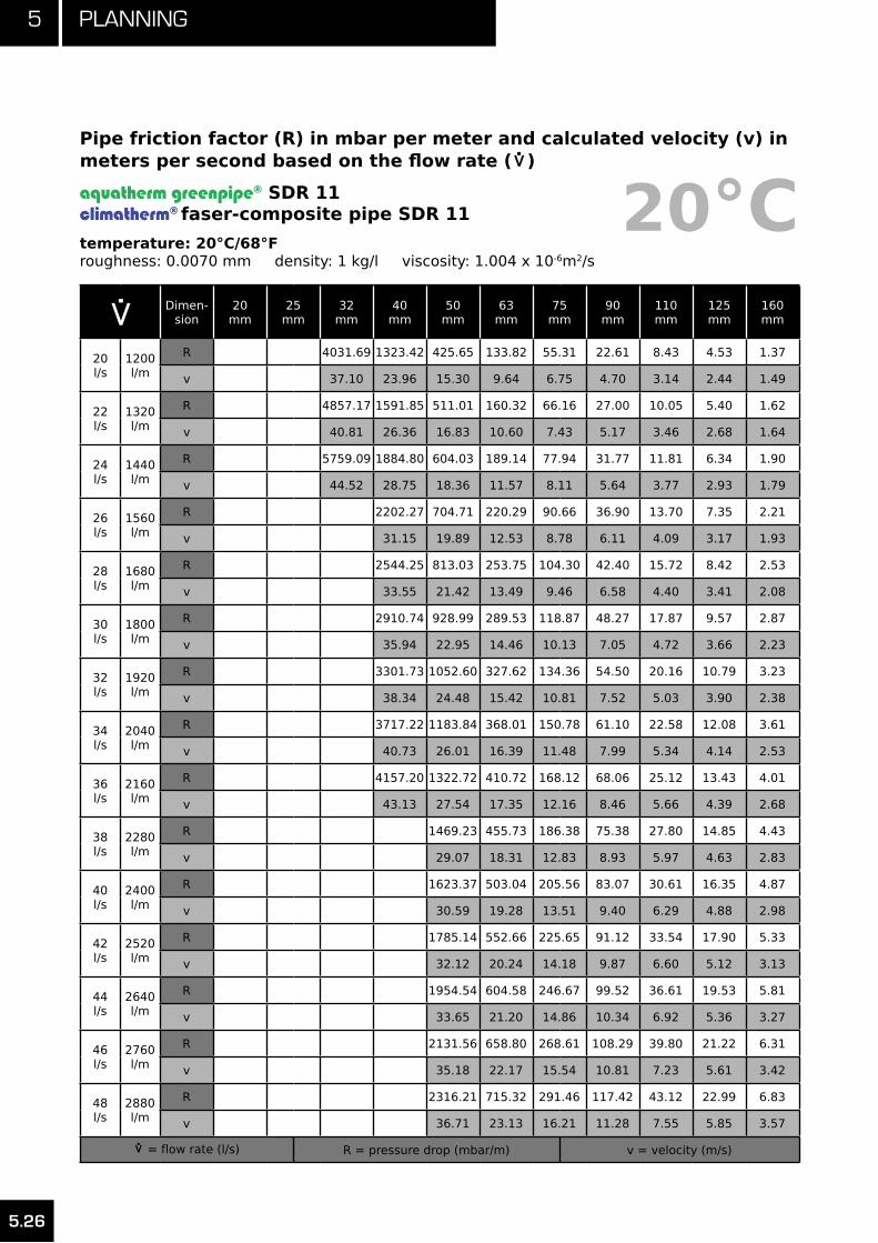
5 Planning
5.26
.>
Dimen-sion
20mm
25mm
32mm
40mm
50mm
63mm
75mm
90mm
110mm
125mm
160mm
20l/s
1200l/m
R 4031.69 1323.42 425.65 133.82 55.31 22.61 8.43 4.53 1.37
v 37.10 23.96 15.30 9.64 6.75 4.70 3.14 2.44 1.49
22l/s
1320l/m
R 4857.17 1591.85 511.01 160.32 66.16 27.00 10.05 5.40 1.62
v 40.81 26.36 16.83 10.60 7.43 5.17 3.46 2.68 1.64
24l/s
1440l/m
R 5759.09 1884.80 604.03 189.14 77.94 31.77 11.81 6.34 1.90
v 44.52 28.75 18.36 11.57 8.11 5.64 3.77 2.93 1.79
26l/s
1560l/m
R 2202.27 704.71 220.29 90.66 36.90 13.70 7.35 2.21
v 31.15 19.89 12.53 8.78 6.11 4.09 3.17 1.93
28l/s
1680l/m
R 2544.25 813.03 253.75 104.30 42.40 15.72 8.42 2.53
v 33.55 21.42 13.49 9.46 6.58 4.40 3.41 2.08
30l/s
1800l/m
R 2910.74 928.99 289.53 118.87 48.27 17.87 9.57 2.87
v 35.94 22.95 14.46 10.13 7.05 4.72 3.66 2.23
32l/s
1920l/m
R 3301.73 1052.60 327.62 134.36 54.50 20.16 10.79 3.23
v 38.34 24.48 15.42 10.81 7.52 5.03 3.90 2.38
34l/s
2040l/m
R 3717.22 1183.84 368.01 150.78 61.10 22.58 12.08 3.61
v 40.73 26.01 16.39 11.48 7.99 5.34 4.14 2.53
36l/s
2160l/m
R 4157.20 1322.72 410.72 168.12 68.06 25.12 13.43 4.01
v 43.13 27.54 17.35 12.16 8.46 5.66 4.39 2.68
38l/s
2280l/m
R 1469.23 455.73 186.38 75.38 27.80 14.85 4.43
v 29.07 18.31 12.83 8.93 5.97 4.63 2.83
40l/s
2400l/m
R 1623.37 503.04 205.56 83.07 30.61 16.35 4.87
v 30.59 19.28 13.51 9.40 6.29 4.88 2.98
42l/s
2520l/m
R 1785.14 552.66 225.65 91.12 33.54 17.90 5.33
v 32.12 20.24 14.18 9.87 6.60 5.12 3.13
44l/s
2640l/m
R 1954.54 604.58 246.67 99.52 36.61 19.53 5.81
v 33.65 21.20 14.86 10.34 6.92 5.36 3.27
46l/s
2760l/m
R 2131.56 658.80 268.61 108.29 39.80 21.22 6.31
v 35.18 22.17 15.54 10.81 7.23 5.61 3.42
48l/s
2880l/m
R 2316.21 715.32 291.46 117.42 43.12 22.99 6.83
v 36.71 23.13 16.21 11.28 7.55 5.85 3.57
.>
= flow rate (l/s) R = pressure drop (mbar/m) v = velocity (m/s)
20°CPipe friction factor (R) in mbar per meter and calculated velocity (v) in meters per second based on the flow rate (
.>
)
aquatherm greenpipe® SDR 11climatherm® faser-composite pipe SDR 11
temperature: 20°C/68°Froughness: 0.0070 mm density: 1 kg/l viscosity: 1.004 x 10⁻⁶m2/s

5.27
5Planning
.>
Dimen-sion
20mm
25mm
32mm
40mm
50mm
63mm
75mm
90mm
110mm
125mm
160mm
50l/s
3000l/m
R 2508.48 774.14 315.22 126.91 46.58 24.81 7.37
v 38.24 24.10 16.89 11.75 7.86 6.10 3.72
52l/s
3120l/m
R 2708.38 835.27 339.91 136.76 50.15 26.71 7.92
v 39.77 25.06 17.56 12.22 8.17 6.34 3.87
54l/s
3240l/m
R 2915.90 898.68 365.51 146.97 53.86 28.67 8.50
v 41.30 26.02 18.24 12.69 8.49 6.58 4.02
56l/s
3360l/m
R 3131.04 964.40 392.02 157.54 57.70 30.70 9.09
v 42.83 26.99 18.91 13.16 8.80 6.83 4.17
58l/s
3480l/m
R 3353.80 1032.42 419.45 168.47 61.66 32.80 9.71
v 44.36 27.95 19.59 13.63 9.12 7.07 4.32
60l/s
3600l/m
R 1102.73 447.80 179.76 65.75 34.96 10.34
v 28.92 20.26 14.10 9.43 7.31 4.47
62l/s
3720l/m
R 1175.34 477.06 191.40 69.97 37.19 10.99
v 29.88 20.94 14.57 9.75 7.56 4.61
64l/s
3840l/m
R 1250.25 507.23 203.41 74.31 39.48 11.66
v 30.84 21.61 15.04 10.06 7.80 4.76
66l/s
3960l/m
R 1327.46 538.32 215.77 78.78 41.84 12.35
v 31.81 22.29 15.51 10.37 8.05 4.91
68l/s
4080l/m
R 1406.96 570.32 228.49 83.38 44.27 13.06
v 32.77 22.97 15.98 10.69 8.29 5.06
70l/s
4200l/m
R 1488.75 603.24 241.56 88.11 46.77 13.79
v 33.74 23.64 16.45 11.00 8.53 5.21
72l/s
4320l/m
R 1572.85 637.07 255.00 92.96 49.33 14.54
v 34.70 24.32 16.92 11.32 8.78 5.36
74l/s
4440l/m
R 1659.23 671.81 268.79 97.94 51.95 15.30
v 35.66 24.99 17.39 11.63 9.02 5.51
76l/s
4560l/m
R 1747.92 707.46 282.94 103.05 54.64 16.09
v 36.63 25.67 17.86 11.95 9.26 5.66
78l/s
4680l/m
R 1838.90 744.03 297.45 108.28 57.40 16.89
v 37.59 26.34 18.33 12.26 9.51 5.80
.>
= flow rate (l/s) R = pressure drop (mbar/m) v = velocity (m/s)
20°CPipe friction factor (R) in mbar per meter and calculated velocity (v) in meters per second based on the flow rate (
.>
)
aquatherm greenpipe® SDR 11climatherm® faser-composite pipe SDR 11
temperature: 20°C/68°Froughness: 0.0070 mm density: 1 kg/l viscosity: 1.004 x 10⁻⁶m2/s

5 Planning
5.28
.> Dim
ension
16mm
20mm
25mm
32mm
40mm
50mm
63mm
75mm
90mm
110mm
125mm
160mm
0.01l/s
0.60l/m
R 0.24 0.09 0.03 0.01 0 0 0 0 0 0 0 0
v 0.09 0.06 0.04 0.02 0.02 0.01 0.01 0 0 0 0 0
0.02l/s
1.20l/m
R 0.75 0.27 0.1 0.03 0.01 0 0 0 0 0 0 0
v 0.19 0.12 0.08 0.05 0.03 0.02 0.01 0.01 0.01 0 0 0
0.03l/s
1.80l/m
R 1.49 0.54 0.19 0.06 0.02 0.01 0 0 0 0 0 0
v 0.28 0.18 0.12 0.07 0.05 0.03 0.02 0.01 0.01 0.01 0 0
0.04l/s
2.40l/m
R 2.43 0.88 0.31 0.09 0.03 0.01 0 0 0 0 0 0
v 0.38 0.25 0.16 0.09 0.06 0.04 0.02 0.02 0.01 0.01 0.01 0
0.05l/s
3.00l/m
R 3.58 1.28 0.45 0.14 0.05 0.02 0.01 0 0 0 0 0
v 0.47 0.31 0.2 0.12 0.08 0.05 0.03 0.02 0.01 0.01 0.01 0
0.06l/s
3.60l/m
R 4.91 1.76 0.61 0.18 0.06 0.02 0.01 0 0 0 0 0
v 0.57 0.37 0.24 0.14 0.09 0.06 0.04 0.03 0.02 0.01 0.01 0.01
0.07l/s
4.20l/m
R 6.42 2.29 0.8 0.24 0.08 0.03 0.01 0 0 0 0 0
v 0.66 0.43 0.28 0.17 0.11 0.07 0.04 0.03 0.02 0.01 0.01 0.01
0.08l/s
4.80l/m
R 8.1 2.89 1 0.3 0.11 0.04 0.01 0.01 0 0 0 0
v 0.76 0.49 0.31 0.19 0.12 0.08 0.05 0.03 0.02 0.02 0.01 0.01
0.09l/s
5.40l/m
R 9.96 3.55 1.23 0.37 0.13 0.05 0.02 0.01 0 0 0 0
v 0.85 0.55 0.35 0.21 0.14 0.09 0.05 0.04 0.03 0.02 0.01 0.01
0.10l/s
6.00l/m
R 11.99 4.27 1.48 0.44 0.15 0.05 0.02 0.01 0 0 0 0
v 0.95 0.61 0.39 0.24 0.15 0.1 0.06 0.04 0.03 0.02 0.02 0.01
0.12l/s
7.20l/m
R 16.5400 5.8700 2.0300 0.6100 0.2100 0.0700 0.0200 0.0100 0.0000 0.0000 0.0000 0
v 1.1400 0.7400 0.4700 0.2800 0.1800 0.1200 0.0700 0.0500 0.0400 0.0200 0.0200 0.01
0.16l/s
9.60l/m
R 27.5600 9.7400 3.3500 1.0000 0.3500 0.1200 0.0400 0.0200 0.0100 0.0000 0.0000 0
v 1.5100 0.9800 0.6300 0.3800 0.2400 0.1600 0.1000 0.0700 0.0500 0.0300 0.0200 0.02
0.18l/s
10.8l/m
R 34.0100 12.0000 4.1200 1.2300 0.4300 0.1500 0.0500 0.0200 0.0100 0.0000 0.0000 0
v 1.7000 1.1100 0.7100 0.4300 0.2700 0.1700 0.1100 0.0800 0.0500 0.0400 0.0300 0.02
0.20l/s
12.0l/m
R 41.07 14.47 4.96 1.48 0.51 0.18 0.06 0.03 0.01 0.00 0.00 0
v 1.89 1.23 0.79 0.47 0.30 0.19 0.12 0.09 0.06 0.04 0.03 0.02
0.30l/s
18.0l/m
R 85.35 29.85 10.17 3.01 1.04 0.36 0.12 0.05 0.02 0.01 0.00 0
v 2.84 1.84 1.18 0.71 0.45 0.29 0.18 0.13 0.09 0.06 0.05 0.03
.>
= flow rate (l/s) R = pressure drop (mbar/m) v = velocity (m/s)
Pipe friction factor (R) in mbar per meter and calculated velocity (v) in meters per second based on the flow rate (
.>
)
aquatherm greenpipe® faser-composite pipe SDR 7.4
temperature: 20°C/68°Froughness: 0.0070 mm density: 1 kg/l viscosity: 1.004 x 10⁻⁶m2/s
20°C

5.29
5Planning
.> Dim
ension
16mm
20mm
25mm
32mm
40mm
50mm
63mm
75mm
90mm
110mm
125mm
160mm
0.40l/s
24.0l/m
R 144.17 50.15 17.00 5.01 1.72 0.60 0.19 0.09 0.04 0.01 0.01 0
v 3.78 2.46 1.57 0.95 0.61 0.39 0.24 0.17 0.12 0.08 0.06 0.04
0.50l/s
30.0l/m
R 217.21 75.21 25.40 7.45 2.55 0.88 0.29 0.13 0.05 0.02 0.01 0
v 4.73 3.07 1.96 1.18 0.76 0.49 0.30 0.22 0.15 0.10 0.08 0.05
0.60l/s
36.0l/m
R 304.25 104.94 35.31 10.33 3.53 1.22 0.40 0.17 0.07 0.03 0.02 0
v 5.68 3.68 2.36 1.42 0.91 0.58 0.36 0.26 0.18 0.12 0.09 0.06
0.70l/s
42.0l/m
R 405.16 139.27 46.72 13.62 4.64 1.60 0.52 0.23 0.10 0.04 0.02 0.01
v 6.62 4.30 2.75 1.66 1.06 0.68 0.42 0.30 0.21 0.14 0.11 0.07
0.80l/s
48.0l/m
R 519.85 178.15 59.60 17.33 5.90 2.03 0.66 0.29 0.12 0.05 0.03 0.01
v 7.57 4.91 3.14 1.89 1.21 0.78 0.49 0.34 0.24 0.16 0.12 0.08
0.90l/s
54.0l/m
R 648.25 221.55 73.92 21.45 7.28 2.5 0.81 0.36 0.15 0.06 0.03 0.01
v 8.52 5.53 3.54 2.13 1.36 0.87 0.55 0.39 0.27 0.18 0.14 0.08
1.00l/s
60.0l/m
R 790.3 269.43 89.69 25.97 8.8 3.02 0.98 0.43 0.18 0.07 0.04 0.01
v 9.46 6.14 3.93 2.37 1.51 0.97 0.61 0.43 0.3 0.2 0.15 0.09
1.20l/s
72.0l/m
R 1115.23 378.58 125.51 36.19 12.23 4.19 1.35 0.59 0.25 0.09 0.05 0.02
v 11.35 7.37 4.72 2.84 1.82 1.17 0.73 0.52 0.36 0.24 0.19 0.11
1.40l/s
84.0l/m
R 1494.4 505.47 166.98 47.97 16.17 5.52 1.78 0.78 0.32 0.12 0.07 0.02
v 13.25 8.6 5.5 3.31 2.12 1.36 0.85 0.6 0.42 0.28 0.22 0.13
1.60l/s
96.0l/m
R 1927.68 650 214.05 61.29 20.61 7.03 2.26 0.99 0.41 0.16 0.09 0.03
v 15.14 9.82 6.29 3.78 2.42 1.55 0.97 0.69 0.48 0.32 0.25 0.15
1.80l/s
108l/m
R 2414.97 812.11 266.69 76.14 25.55 8.69 2.79 1.22 0.5 0.19 0.1 0.03
v 17.03 11.05 7.07 4.26 2.73 1.75 1.09 0.77 0.54 0.36 0.28 0.17
2.00l/s
120l/m
R 2956.18 991.77 324.88 92.51 30.97 10.52 3.37 1.47 0.61 0.23 0.13 0.04
v 18.92 12.28 7.86 4.73 3.03 1.94 1.21 0.86 0.6 0.4 0.31 0.19
2.20l/s
132l/m
R 3551.28 1188.92 388.58 110.38 36.89 12.51 4 1.75 0.72 0.28 0.15 0.05
v 20.82 13.51 8.65 5.2 3.33 2.14 1.34 0.95 0.65 0.44 0.34 0.21
2.40l/s
144l/m
R 4200.22 1403.55 457.79 129.75 43.28 14.66 4.68 2.04 0.84 0.32 0.17 0.05
v 22.71 14.74 9.43 5.68 3.63 2.33 1.46 1.03 0.71 0.48 0.37 0.23
2.60l/s
156l/m
R 4902.97 1635.62 532.49 150.61 50.15 16.96 5.41 2.36 0.97 0.37 0.2 0.06
v 24.6 15.96 10.22 6.15 3.94 2.53 1.58 1.12 0.77 0.52 0.4 0.25
.>
= flow rate (l/s) R = pressure drop (mbar/m) v = velocity (m/s)
20°CPipe friction factor (R) in mbar per meter and calculated velocity (v) in meters per second based on the flow rate (
.>
)
aquatherm greenpipe® faser-composite pipe SDR 7.4
temperature: 20°C/68°Froughness: 0.0070 mm density: 1 kg/l viscosity: 1.004 x 10⁻⁶m2/s

5 Planning
5.30
.> Dim
ension
16mm
20mm
25mm
32mm
40mm
50mm
63mm
75mm
90mm
110mm
125mm
160mm
2.80l/s
168l/m
R 5659.51 1885.14 612.68 172.95 57.51 19.42 6.19 2.69 1.11 0.43 0.23 0.07
v 26.49 17.19 11 6.62 4.24 2.72 1.7 1.2 0.83 0.56 0.43 0.26
3.00l/s
180l/m
R 6469.83 2152.07 698.33 196.77 65.33 22.04 7.02 3.05 1.25 0.48 0.26 0.08
v 28.39 18.42 11.79 7.1 4.54 2.91 1.82 1.29 0.89 0.6 0.46 0.28
3.20l/s
192l/m
R 7333.9 2436.42 789.45 222.07 73.63 24.81 7.89 3.43 1.41 0.54 0.29 0.09
v 30.28 19.65 12.58 7.57 4.84 3.11 1.94 1.38 0.95 0.64 0.49 0.3
3.40l/s
204l/m
R 8251.71 2738.16 886.03 248.84 82.39 27.73 8.81 3.82 1.57 0.6 0.32 0.1
v 32.17 20.88 13.36 8.04 5.15 3.3 2.06 1.46 1.01 0.68 0.53 0.32
3.60l/s
216l/m
R 9223.26 3057.3 988.06 277.08 91.63 30.8 9.78 4.24 1.74 0.67 0.36 0.11
v 34.06 22.1 14.15 8.52 5.45 3.5 2.19 1.55 1.07 0.72 0.56 0.34
3.80l/s
228l/m
R 10248.54 3393.82 1095.53 306.79 101.33 34.02 10.79 4.68 1.92 0.74 0.4 0.12
v 35.96 23.33 14.93 8.99 5.75 3.69 2.31 1.63 1.13 0.76 0.59 0.36
4.00l/s
240l/m
R 11327.55 3747.73 1208.45 337.96 111.5 37.4 11.85 5.13 2.11 0.81 0.43 0.13
v 37.85 24.56 15.72 9.46 6.06 3.89 2.43 1.72 1.19 0.8 0.62 0.38
4.20l/s
252l/m
R 12460.26 4119.01 1326.81 370.59 122.13 40.93 12.95 5.61 2.3 0.88 0.47 0.14
v 39.74 25.79 16.5 9.94 6.36 4.08 2.55 1.81 1.25 0.84 0.65 0.4
4.4l/s
264l/m
R 13646.69 4507.66 1450.61 404.68 133.23 44.6 14.1 6.11 2.5 0.96 0.51 0.16
v 41.63 27.02 17.29 10.41 6.66 4.28 2.67 1.89 1.31 0.88 0.68 0.41
4.60l/s
276l/m
R 14886.82 4913.68 1579.84 440.23 144.79 48.43 15.3 6.62 2.71 1.04 0.56 0.17
v 43.53 28.25 18.08 10.88 6.96 4.47 2.79 1.98 1.37 0.92 0.71 0.43
4.80l/s
288l/m
R 16180.66 5337.07 1714.51 477.24 156.81 52.4 16.54 7.15 2.93 1.12 0.6 0.18
v 45.42 29.47 18.86 11.35 7.27 4.66 2.91 2.07 1.43 0.96 0.74 0.45
5l/s
300l/m
R
5777.81 1854.6 515.71 169.29 56.53 17.83 7.71 3.15 1.21 0.65 0.2
v
30.70 19.65 11.83 7.57 4.86 3.03 2.15 1.49 1 0.77 0.47
5.2l/s
312l/m
R
6235.92 2000.12 555.63 182.23 60.8 19.16 8.28 3.39 1.29 0.69 0.21
v
31.93 20.43 12.3 7.87 5.05 3.16 2.24 1.55 1.04 0.8 0.49
5.40l/s
324l/m
R
6711.39 2151.07 597 195.64 65.22 20.54 8.87 3.63 1.39 0.74 0.23
v
33.16 21.22 12.77 8.18 5.25 3.28 2.32 1.61 1.08 0.83 0.51
5.60l/s
336l/m
R
7204.21 2307.44 639.83 209.5 69.78 21.96 9.48 3.87 1.48 0.79 0.24
v
34.39 22.01 13.25 8.48 5.44 3.4 2.41 1.67 1.12 0.86 0.53
.>
= flow rate (l/s) R = pressure drop (mbar/m) v = velocity (m/s)
20°CPipe friction factor (R) in mbar per meter and calculated velocity (v) in meters per second based on the flow rate (
.>
)
aquatherm greenpipe® faser-composite pipe SDR 7.4
temperature: 20°C/68°Froughness: 0.0070 mm density: 1 kg/l viscosity: 1.004 x 10⁻⁶m2/s

5.31
5Planning
.> Dim
ension
16mm
20mm
25mm
32mm
40mm
50mm
63mm
75mm
90mm
110mm
125mm
160mm
5.80l/s
348l/m
R
7714.39 2469.24 684.11 223.82 74.5 23.43 10.11 4.13 1.58 0.85 0.26
v
35.61 22.79 13.72 8.78 5.64 3.52 2.5 1.73 1.16 0.9 0.55
6.00l/s
360l/m
R
8241.92 2636.46 729.84 238.6 79.36 24.94 10.76 4.39 1.68 0.9 0.27
v
36.84 23.58 14.19 9.08 5.83 3.64 2.58 1.79 1.2 0.93 0.57
6.2l/s
372l/m
R
8786.80 2809.1 777.02 253.84 84.37 26.5 11.42 4.66 1.78 0.95 0.29
v
38.07 24.36 14.67 9.39 6.02 3.76 2.67 1.85 1.24 0.96 0.58
6.40l/s
384l/m
R
9349.04 2987.16 825.65 269.53 89.52 28.1 12.11 4.94 1.88 1.01 0.31
v
39.30 25.15 15.14 9.69 6.22 3.88 2.75 1.91 1.28 0.99 0.6
6.60l/s
396l/m
R
9928.62 3170.64 875.73 285.68 94.82 29.74 12.81 5.23 1.99 1.07 0.33
v
40.53 25.94 15.61 9.99 6.41 4.01 2.84 1.96 1.32 1.02 0.62
6.80l/s
408l/m
R
10525.55 3359.54 927.25 302.29 100.27 31.43 13.53 5.52 2.1 1.13 0.34
v
41.75 26.72 16.09 10.29 6.61 4.13 2.93 2.02 1.36 1.05 0.64
7.00l/s
420l/m
R
11139.83 3553.86 980.23 319.36 105.86 33.16 14.27 5.82 2.22 1.19 0.36
v
42.98 27.51 16.56 10.6 6.8 4.25 3.01 2.08 1.4 1.08 0.66
7.50l/s
450l/m
R
12751.43 4063.35 1119 364.01 120.49 37.69 16.21 6.6 2.51 1.34 0.41
v
46.0529.47 17.74 11.35 7.29 4.55 3.23 2.23 1.5 1.16 0.71
8.00l/s
480l/m
R
14471.43 4606.69 1266.81 411.52 136.02 42.49 18.25 7.43 2.82 1.51 0.46
v
49.1231.44 18.92 12.11 7.77 4.86 3.44 2.38 1.6 1.24 0.75
9.00l/s
540l/m
R
18236.63 5794.9 1589.53 515.05 169.8 52.9 22.69 9.22 3.5 1.87 0.57
v
55.26 35.37 21.29 13.63 8.74 5.46 3.87 2.68 1.8 1.39 0.85
10l/s
600l/m
R
7118.43 1948.35 629.93 207.19 64.4 27.58 11.19 4.24 2.27 0.69
v
39.30 23.66 15.14 9.72 6.07 4.3 2.98 2 1.54 0.94
12.0l/s
720l/m
R
10171.36 2774.23 893.66 292.78 90.64 38.7 15.66 5.92 3.16 0.96
v
47.16 28.39 18.17 11.66 7.28 5.16 3.57 2.4 1.85 1.13
14.0l/s
840l/m
R
13765.32 3744.31 1202.62 392.73 121.15 51.6 20.83 7.86 4.19 1.27
v
55.02 33.12 21.2 13.6 8.5 6.02 4.17 2.8 2.16 1.32
16l/s
960l/m
R
4858.51 1556.75 506.99 155.92 66.27 26.69 10.05 5.35 1.61
v
37.85 24.22 15.55 9.71 6.88 4.76 3.2 2.47 1.51
18.0l/s
1080l/m
R
6116.78 1956 635.54 194.94 82.7 33.24 12.5 6.65 2
v
42.58 27.25 17.49 10.93 7.74 5.36 3.6 2.78 1.7
.>
= flow rate (l/s) R = pressure drop (mbar/m) v = velocity (m/s)
20°CPipe friction factor (R) in mbar per meter and calculated velocity (v) in meters per second based on the flow rate (
.>
)
aquatherm greenpipe® faser-composite pipe SDR 7.4
temperature: 20°C/68°Froughness: 0.0070 mm density: 1 kg/l viscosity: 1.004 x 10⁻⁶m2/s

5 Planning
5.32
.> Dim
ension
16mm
20mm
25mm
32mm
40mm
50mm
63mm
75mm
90mm
110mm
125mm
160mm
20.0l/s
1200l/m
R
7519.10 2400.35 778.35 238.19 100.87 40.48 15.19 8.07 2.43
v
47.31 30.28 19.43 12.14 8.6 5.95 4 3.09 1.89
22.0
l/s
1320l/m
R
9065.44 2889.78 935.41 285.66 120.79 48.39 18.13 9.62 2.89
v
52.04 33.31 21.38 13.35 9.47 6.55 4.4 3.4 2.07
24.0l/s
1440l/m
R
10755.78 3424.28 1106.72 337.35 142.44 56.98 21.32 11.31 3.39
v
56.77 36.34 23.32 14.57 10.33 7.14 4.8 3.71 2.26
26l/s
1560l/m
R
4003.83 1292.25 393.24 165.83 66.25 24.75 13.11 3.92
v
39.36 25.26 15.78 11.19 7.74 5.2 4.02 2.45
28.0l/s
1680l/m
R
4628.43 1492.01 453.33 190.94 76.18 28.43 15.05 4.5
v
42.39 27.21 17 12.05 8.34 5.6 4.32 2.64
30.0l/s
1800l/m
R
5298.07 1705.99 517.63 217.78 86.79 32.35 17.11 5.11
v
45.42 29.15 18.21 12.91 8.93 6 4.63 2.83
32.0l/s
1920l/m
R
6012.75 1934.18 586.12 246.35 98.06 36.51 19.3 5.75
v
48.45 31.09 19.42 13.77 9.53 6.4 4.94 3.02
34.0l/s
2040l/m
R
6772.46 2176.59 658.81 276.64 110 40.91 21.61 6.44
v
51.47 33.03 20.64 14.63 10.12 6.8 5.25 3.21
36.0l/s
2160l/m
R
7577.20 2433.21 735.69 308.65 122.61 45.55 24.05 7.15
v
54.50 34.98 21.85 15.49 10.72 7.2 5.56 3.39
38l/s
2280l/m
R
2704.03 816.76 342.38 135.89 50.43 26.61 7.91
v
36.92 23.07 16.35 11.31 7.6 5.87 3.58
40.0l/s
2400l/m
R
2989.06 902.01 377.83 149.83 55.55 29.3 8.7
v
38.86 24.28 17.21 11.91 8 6.18 3.77
42.0l/s
2520l/m
R
3288.29 991.46 414.99 164.43 60.91 32.11 9.52
v
40.81 25.49 18.07 12.5 8.4 6.49 3.96
44.0l/s
2640l/m
R
3601.72 1085.09 453.87 179.69 66.51 35.04 10.38
v
42.75 26.71 18.93 13.1 8.8 6.8 4.15
46.0l/s
2760l/m
R
3929.35 1182.9 494.47 195.62 72.35 38.09 11.28
v
44.69 27.92 19.79 13.69 9.2 7.1 4.34
48.0l/s
2880l/m
R
4271.18 1284.9 536.78 212.21 78.43 41.27 12.21
v
46.64 29.14 20.65 14.29 9.6 7.41 4.53
.>
= flow rate (l/s) R = pressure drop (mbar/m) v = velocity (m/s)
20°CPipe friction factor (R) in mbar per meter and calculated velocity (v) in meters per second based on the flow rate (
.>
)
aquatherm greenpipe® faser-composite pipe SDR 7.4
temperature: 20°C/68°Froughness: 0.0070 mm density: 1 kg/l viscosity: 1.004 x 10⁻⁶m2/s

5.33
5Planning
.> Dim
ension
16mm
20mm
25mm
32mm
40mm
50mm
63mm
75mm
90mm
110mm
125mm
160mm
50.0l/s
3000l/m
R
4627.22 1391.08 580.81 229.47 84.74 44.57 13.17
v
48.58 30.35 21.51 14.88 10 7.72 4.71
52.0l/s
3120l/m
R
4997.44 1501.45 626.55 247.38 91.29 48 14.18
v
50.52 31.56 22.37 15.48 10.4 8.03 4.9
54.0l/s
3240l/m
R
5381.87 1616 674 265.95 98.08 51.54 15.21
v
52.47 32.78 23.23 16.07 10.8 8.34 5.09
56l/s
3360l/m
R
5780.49 1734.73 723.17 285.19 105.1 55.21 16.28
v
54.41 33.99 24.09 16.67 11.2 8.65 5.28
58.0l/s
3480l/m
R
6193.31 1857.64 774.05 305.08 112.36 59 17.39
v
56.35 35.21 24.95 17.27 11.6 8.96 5.47
60l/s
3600l/m
R
1984.73 826.64 325.64 119.86 62.91 18.53
v
36.42 25.81 17.86 12 9.27 5.66
62.0l/s
3720l/m
R
2116.00 880.94 346.85 127.59 66.95 19.7
v
37.63 26.67 18.46 12.4 9.57 5.85
64.0l/s
3840l/m
R
2251.45 936.96 368.73 135.56 71.1 20.91
v
38.85 27.54 19.05 12.8 9.88 6.04
66.0l/s
3960l/m
R
2391.08 994.68 391.26 143.77 75.38 22.15
v
40.06 28.4 19.65 13.2 10.19 6.22
68.0l/s
4080l/m
R
2534.89 1054.12 414.46 152.21 79.78 23.43
v
41.28 29.26 20.24 13.6 10.5 6.41
70.0l/s
4200l/m
R
2682.88 1115.27 438.31 160.89 84.3 24.74
v
42.49 30.12 20.84 14 10.81 6.6
72.0l/s
4320l/m
R
2835.05 1178.12 462.82 169.8 88.94 26.09
v
43.70 30.98 21.43 14.4 11.12 6.79
74.0l/s
4440l/m
R
2991.40 1242.69 487.99 178.95 93.7 27.47
v
44.92 31.84 22.03 14.8 11.43 6.98
76.0l/s
4560l/m
R
3151.92 1308.97 513.82 188.34 98.59 28.88
v
46.13 32.7 22.62 15.2 11.74 7.17
78.0l/s
4680l/m
R
3316.63 1376.96 540.31 197.96 103.59 30.33
v
47.35 33.56 23.22 15.6 12.05 7.36
.>
= flow rate (l/s) R = pressure drop (mbar/m) v = velocity (m/s)
20°CPipe friction factor (R) in mbar per meter and calculated velocity (v) in meters per second based on the flow rate (
.>
)
aquatherm greenpipe® faser-composite pipe SDR 7.4
temperature: 20°C/68°Froughness: 0.0070 mm density: 1 kg/l viscosity: 1.004 x 10⁻⁶m2/s
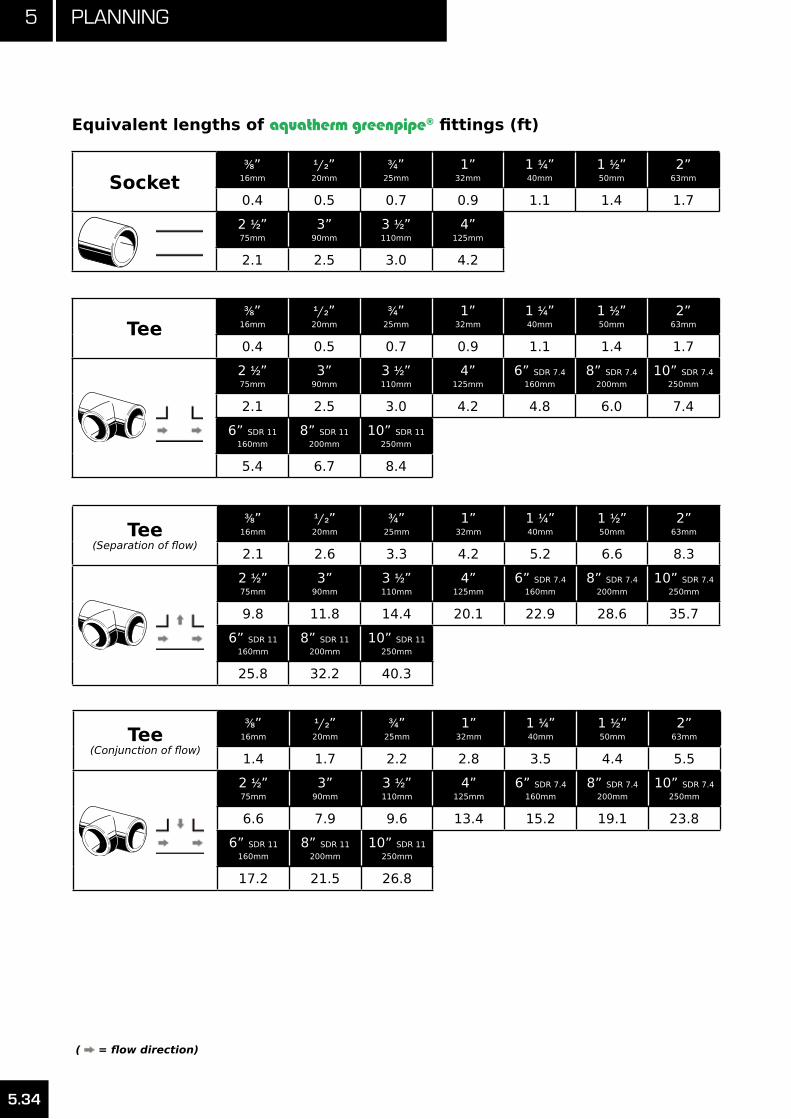
5 Planning
5.34
Socket3⁄8”
16mm
1/2”20mm
3⁄4”25mm
1”32mm
1 1⁄4”40mm
1 1⁄2”50mm
2”63mm
0.4 0.5 0.7 0.9 1.1 1.4 1.7
2 1⁄2”75mm
3”90mm
3 1⁄2”110mm
4”125mm
2.1 2.5 3.0 4.2
11010
Equivalent lengths of aquatherm greenpipe® fittings (ft)
Tee3⁄8”
16mm
1/2”20mm
3⁄4”25mm
1”32mm
1 1⁄4”40mm
1 1⁄2”50mm
2”63mm
0.4 0.5 0.7 0.9 1.1 1.4 1.7
2 1⁄2”75mm
3”90mm
3 1⁄2”110mm
4”125mm
6” SDR 7.4
160mm
8” SDR 7.4
200mm
10” SDR 7.4
250mm
2.1 2.5 3.0 4.2 4.8 6.0 7.4
6” SDR 11
160mm
8” SDR 11
200mm
10” SDR 11
250mm
5.4 6.7 8.4
13108
Tee(Separation of flow)
3⁄8”16mm
1/2”20mm
3⁄4”25mm
1”32mm
1 1⁄4”40mm
1 1⁄2”50mm
2”63mm
2.1 2.6 3.3 4.2 5.2 6.6 8.3
2 1⁄2”75mm
3”90mm
3 1⁄2”110mm
4”125mm
6” SDR 7.4
160mm
8” SDR 7.4
200mm
10” SDR 7.4
250mm
9.8 11.8 14.4 20.1 22.9 28.6 35.7
6” SDR 11
160mm
8” SDR 11
200mm
10” SDR 11
250mm
25.8 32.2 40.3
13108
Tee(Conjunction of flow)
3⁄8”16mm
1/2”20mm
3⁄4”25mm
1”32mm
1 1⁄4”40mm
1 1⁄2”50mm
2”63mm
1.4 1.7 2.2 2.8 3.5 4.4 5.5
2 1⁄2”75mm
3”90mm
3 1⁄2”110mm
4”125mm
6” SDR 7.4
160mm
8” SDR 7.4
200mm
10” SDR 7.4
250mm
6.6 7.9 9.6 13.4 15.2 19.1 23.8
6” SDR 11
160mm
8” SDR 11
200mm
10” SDR 11
250mm
17.2 21.5 26.8
13108
( = flow direction)

5.35
5Planning
Tee(Counter current in case
of conjunction of flow)
3⁄8”16mm
1/2”20mm
3⁄4”25mm
1”32mm
1 1⁄4”40mm
1 1⁄2”50mm
2”63mm
5.2 6.5 8.2 10.4 13.1 16.4 20.7
2 1⁄2”75mm
3”90mm
3 1⁄2”110mm
4”125mm
6” SDR 7.4
160mm
8” SDR 7.4
200mm
10” SDR 7.4
250mm
24.6 29.5 36.1 50.3 57.2 71.5 89.3
6” SDR 11
160mm
8” SDR 11
200mm
10” SDR 11
250mm
64.4 80.5 100.7
13108
( = flow direction)
Tee(Counter current in case
of separation of flow)
3⁄8”16mm
1/2”20mm
3⁄4”25mm
1”32mm
1 1⁄4”40mm
1 1⁄2”50mm
2”63mm
3.1 3.9 4.9 6.3 7.9 9.9 12.4
2 1⁄2”75mm
3”90mm
3 1⁄2”110mm
4”125mm
6” SDR 7.4
160mm
8” SDR 7.4
200mm
10” SDR 7.4
250mm
14.8 17.7 21.7 30.2 34.3 42.9 53.6
6” SDR 11
160mm
8” SDR 11
200mm
10” SDR 11
250mm
38.7 48.3 60.4
13108
Bushing(by 1 dimension)
3⁄8”16mm
1/2”20mm
3⁄4”25mm
1”32mm
1 1⁄4”40mm
1 1⁄2”50mm
2”63mm
0.9 1.1 1.4 1.7 2.2 2.8
2 1⁄2”75mm
3”90mm
3 1⁄2”110mm
4”125mm
6” SDR 7.4
160mm
8” SDR 7.4
200mm
10” SDR 7.4
250mm
3.3 3.9 4.8 6.7 7.6 9.5 11.9
6” SDR 11
160mm
8” SDR 11
200mm
10” SDR 11
250mm
8.6 10.7 13.4
11134
Bushing(by 2 dimensions)
3⁄8”16mm
1/2”20mm
3⁄4”25mm
1”32mm
1 1⁄4”40mm
1 1⁄2”50mm
2”63mm
1.4 1.7 2.2 2.7 3.4
2 1⁄2”75mm
3”90mm
3 1⁄2”110mm
4”125mm
6” SDR 7.4
160mm
8” SDR 7.4
200mm
10” SDR 7.4
250mm
4.1 4.9 6.0 8.4 9.5 11.9 14.9
6” SDR 11
160mm
8” SDR 11
200mm
10” SDR 11
250mm
10.7 13.4 16.8
11134
Equivalent lengths of aquatherm greenpipe® fittings (ft)

5 Planning
5.36
Equivalent lengths of aquatherm greenpipe® fittings (ft)
Bushing(by 3 dimensions)
3⁄8”16mm
1/2”20mm
3⁄4”25mm
1”32mm
1 1⁄4”40mm
1 1⁄2”50mm
2”63mm
2.1 2.6 3.3 4.1
2 1⁄2”75mm
3”90mm
3 1⁄2”110mm
4”125mm
6” SDR 7.4
160mm
8” SDR 7.4
200mm
10” SDR 7.4
250mm
4.9 5.9 7.2 10.1 11.4 14.3 17.9
6” SDR 11
160mm
8” SDR 11
200mm
10” SDR 11
250mm
12.9 16.1 20.1
Bushing(by 4 dimensions)
3⁄8”16mm
1/2”20mm
3⁄4”25mm
1”32mm
1 1⁄4”40mm
1 1⁄2”50mm
2”63mm
3.1 3.8 4.8
2 1⁄2”75mm
3”90mm
3 1⁄2”110mm
4”125mm
6” SDR 7.4
160mm
8” SDR 7.4
200mm
10” SDR 7.4
250mm
5.7 6.9 8.4 11.7 13.3 16.7 20.8
6” SDR 11
160mm
8” SDR 11
200mm
10” SDR 11
250mm
15.0 18.8 23.5
Bushing(by 5 dimensions)
3⁄8”16mm
1/2”20mm
3⁄4”25mm
1”32mm
1 1⁄4”40mm
1 1⁄2”50mm
2”63mm
4.4 5.5
2 1⁄2”75mm
3”90mm
3 1⁄2”110mm
4”125mm
6” SDR 7.4
160mm
8” SDR 7.4
200mm
10” SDR 7.4
250mm
6.6 7.9 9.6 13.4 15.2 19.1 23.8
6” SDR 11
160mm
8” SDR 11
200mm
10” SDR 11
250mm
17.2 21.5 26.8
Bushing(by 6 dimensions)
3⁄8”16mm
1/2”20mm
3⁄4”25mm
1”32mm
1 1⁄4”40mm
1 1⁄2”50mm
2”63mm
6.2
2 1⁄2”75mm
3”90mm
3 1⁄2”110mm
4”125mm
6” SDR 7.4
160mm
8” SDR 7.4
200mm
10” SDR 7.4
250mm
7.4 8.9 10.8 15.1 17.2 21.4 26.8
6” SDR 11
160mm
8” SDR 11
200mm
10” SDR 11
250mm
19.3 24.2 30.2
11134
11134
11134
11134
( = flow direction)
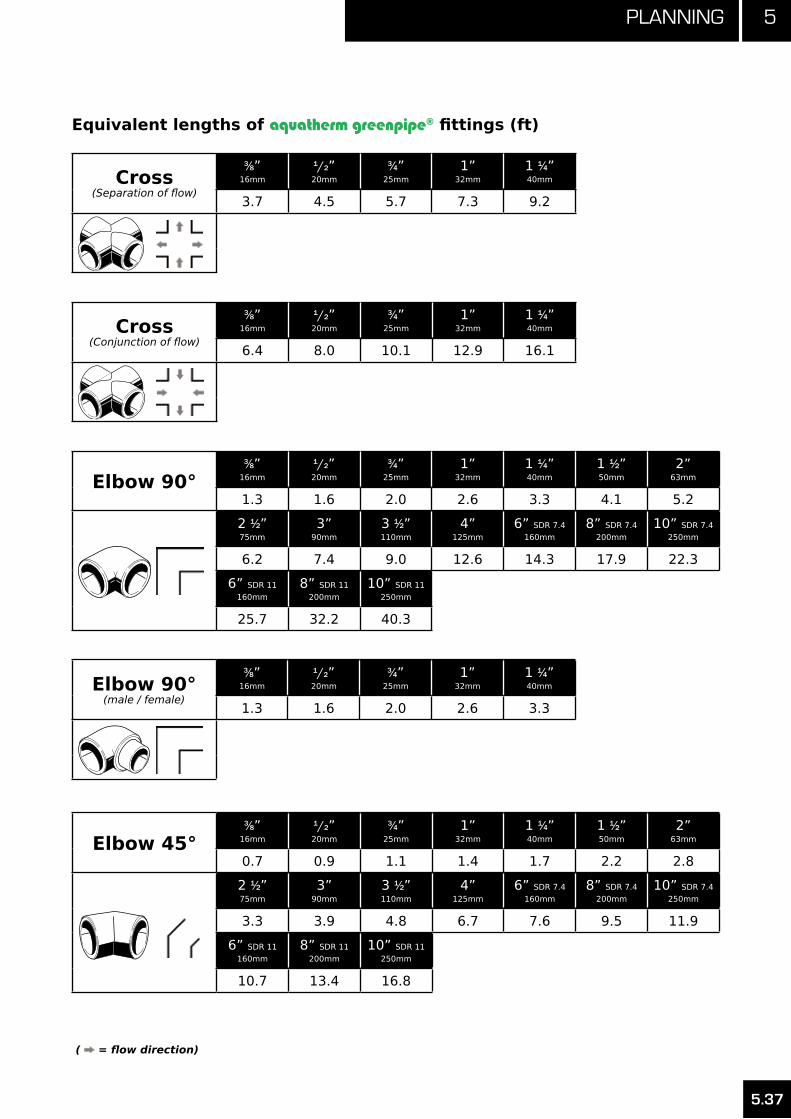
5.37
5Planning
Equivalent lengths of aquatherm greenpipe® fittings (ft)
Cross(Separation of flow)
3⁄8”16mm
1/2”20mm
3⁄4”25mm
1”32mm
1 1⁄4”40mm
3.7 4.5 5.7 7.3 9.213708
Cross(Conjunction of flow)
3⁄8”16mm
1/2”20mm
3⁄4”25mm
1”32mm
1 1⁄4”40mm
6.4 8.0 10.1 12.9 16.113708
Elbow 90°3⁄8”
16mm
1/2”20mm
3⁄4”25mm
1”32mm
1 1⁄4”40mm
1 1⁄2”50mm
2”63mm
1.3 1.6 2.0 2.6 3.3 4.1 5.2
2 1⁄2”75mm
3”90mm
3 1⁄2”110mm
4”125mm
6” SDR 7.4
160mm
8” SDR 7.4
200mm
10” SDR 7.4
250mm
6.2 7.4 9.0 12.6 14.3 17.9 22.3
6” SDR 11
160mm
8” SDR 11
200mm
10” SDR 11
250mm
25.7 32.2 40.3
12106
Elbow 90°(male / female)
3⁄8”16mm
1/2”20mm
3⁄4”25mm
1”32mm
1 1⁄4”40mm
1.3 1.6 2.0 2.6 3.312308
Elbow 45°3⁄8”
16mm
1/2”20mm
3⁄4”25mm
1”32mm
1 1⁄4”40mm
1 1⁄2”50mm
2”63mm
0.7 0.9 1.1 1.4 1.7 2.2 2.8
2 1⁄2”75mm
3”90mm
3 1⁄2”110mm
4”125mm
6” SDR 7.4
160mm
8” SDR 7.4
200mm
10” SDR 7.4
250mm
3.3 3.9 4.8 6.7 7.6 9.5 11.9
6” SDR 11
160mm
8” SDR 11
200mm
10” SDR 11
250mm
10.7 13.4 16.8
12506
( = flow direction)

5 Planning
5.38
Equivalent lengths of aquatherm greenpipe® fittings (ft)
Elbow 45°(male / female)
3⁄8”16mm
1/2”20mm
3⁄4”25mm
1”32mm
1 1⁄4”40mm
0.7 0.9 1.1 1.4 1.7
( = flow direction)
12708
Transition(female thread)
3⁄8”16mm
1/2”20mm
3⁄4”25mm
1”32mm
1 1⁄4”40mm
1 1⁄2”50mm
2”63mm
0.9 1.1 1.4 1.7 2.2 2.7 3.4
2 1⁄2”75mm
4.1
21108
Transition(male thread)
3⁄8”16mm
1/2”20mm
3⁄4”25mm
1”32mm
1 1⁄4”40mm
1 1⁄2”50mm
2”63mm
1.2 1.5 1.9 2.4 3.1 3.8 4.8
2 1⁄2”75mm
3”90mm
3 1⁄2”110mm
5.7 6.9 8.4
Elbow(female thread)
3⁄8”16mm
1/2”20mm
3⁄4”25mm
1”32mm
1.5 1.9 2.4 3.0
Elbow(male thread)
3⁄8”16mm
1/2”20mm
3⁄4”25mm
1”32mm
1.7 2.2 2.7 3.5
Tee(female thread)
3⁄8”16mm
1/2”20mm
3⁄4”25mm
1”32mm
2.8 3.5 4.4 5.6
21308
23008
23508
25006

5.39
5Planning
Equivalent lengths of aquatherm greenpipe® fittings (ft)
Tee(male thread)
1/2”20mm
3.9
( = flow direction)
25506
Fusion outlet3⁄8”
16mm
1/2”20mm
3⁄4”25mm
1”32mm
1 1⁄4”40mm
1 1⁄2”50mm
2”63mm
0.4 0.5 0.7 0.9 1.1 1.4 1.7
2 1⁄2”75mm
3”90mm
3 1⁄2”110mm
4”125mm
6”160mm
8”200mm
10”250mm
2.1 2.5 3.0 4.2 5.4 6.7 8.4
Fusion outlet(separation of flow)
3⁄8”16mm
1/2”20mm
3⁄4”25mm
1”32mm
1 1⁄4”40mm
1 1⁄2”50mm
2”63mm
0.9 1.1 1.4 1.7 2.2 2.7 3.4
2 1⁄2”75mm
3”90mm
3 1⁄2”110mm
4”125mm
6”160mm
8”200mm
10”250mm
4.1 4.9 6.0 8.4 10.7 13.4 16.8
Fusion outlet(Counter current in case of conjunction of flow)
3⁄8”16mm
1/2”20mm
3⁄4”25mm
1”32mm
1 1⁄4”40mm
1 1⁄2”50mm
2”63mm
1.7 2.2 2.7 3.5 4.4 5.5 6.9
2 1⁄2”75mm
3”90mm
3 1⁄2”110mm
4”125mm
6”160mm
8”200mm
10”250mm
8.2 9.8 12.0 16.8 21.5 26.8 33.6

5 Planning
5.40
Picture Comment Picture CommentEquivalent
LengthPotable water
installation Reduced 3⁄4”(25 mm)passage for
separation of flow
Heating installationReduced 1/2” (20 mm) passage for separation of flow
2.0
3⁄4”(25 mm) passage for separation of flow
1/2” (20 mm) passage for separation of flow
0.5
Potable waterinstallation
1/2” (20 mm) passage for separation of flow
Heating installation 3⁄8” (16 mm) branch for separation of flow 1.6
1/2” (20 mm) branch for conjunction of flow
3⁄8” (16 mm) branch in case of conjunction
of flow3.2
Reduced 1/2”(20 mm) passage for
separation of flow
3⁄8” (16 mm) branch for separation of flow 4.4
Potable water installation
3⁄4”(25 mm) branch for separation of flow
2.4
3⁄8” (16 mm) branch for conjunction of flow 1.6
Coldwater
Hotwater
Coldwater
Hotwater
Return
Flow
Flow
Return
Coldwater
Coldwater
Hotwater
Hotwater
Hotwaterreturn
Equivalent lengths of aquatherm greenpipe® fittings (ft) - distribution block

Pipes and Fittings
aquatherm greenpipe® faser-composite pipe SDR 7.4
aquatherm greenpipe® SDR 11
climatherm® faser-composite pipe SDR 11 / 7.4
aquatherm greenpipe® SDR 7.4
aquatherm greenpipe® faser-composite pipe SDR 7.4 UV
climatherm® faser-composite pipe SDR 11 UV
aquatherm® - lilac pipe SDR 11
aquatherm Advanced
Accessories
Fittings
Flanges
Couplings
Mounting devices Threaded connections
Transition pieces
Distributors
Valves
Tools


6.1
6Product range
aquatherm greenpipe®
faser-composite pipe SDR 7.4
Material: Fusiolen® PP-R faser-composite
In accordance with:NSF-14•NSF-51•NSF-61•CSA-B137.11•ICC AC 122 •ICC ESR 1613•ASTM F 2389•CFIA #A508•
NSF System Certification:Including fittings, connection pieces, and connection techniques.
Fields of Application:For high temperature, moderate pressure systems, particularly domestic hot water systems.
Pipe * Diameter **Wall
thicknessInternal
diameterWater
capacityWeight ***
Art.-No.Dimension
Nom. I.D. -- O.D.Packing
unitd (mm) s (mm) di (mm) gal/ft lb/ft
0670708 1/2” -- 20 X 2.8 mm 25 20 2.8 14.4 0.0131 0.106
0670710 3/4” -- 25 X 3.5 mm 25 25 3.5 18 0.024 0.165
0670712 1” -- 32 X 4.4 mm 10 32 4.4 23.2 0.0340 0.265
0670714 1.25” -- 40 X 5.5 mm 10 40 5.5 29 0.0531 0.412
0670716 1.5” -- 50 X 6.9 mm 5 50 6.9 36.2 0.0828 0.642
0670718 2” -- 63 X 8.6 mm 5 63 8.6 45.8 0.1325 1.008
0670720 2.5” -- 75 X 10.3 mm 5 75 10.3 54.4 0.1870 1.435
0670722 3” -- 90 X 12.3 mm 3 90 12.3 65.4 0.2703 2.055
0670724 3.5” -- 110 X 15.1 mm 2 110 15.1 79.8 0.4023 3.075
0670726 4” -- 125 X 17.1 mm 1 125 17.1 90.8 0.521 3.959
0670730 6” -- 160 X 21.9 mm 1 160 21.9 116.2 0.854 6.409
0670734 8” -- 200 X 27.4 mm 1 200 27.4 145.2 1.333 10.114
0670738 10” -- 250 x 34.2 mm 1 250 34.2 181.6 2.084 15.777
* Pipes come in standard 13 ft lengths (4 m).
** To calculate exact dimensions of the pipe in imperial inches, divide measurement by 25.4.
*** To calculate the weight of the pipe in kg/m, multiply the measurement by 1.5.

6 Product range
6.2
aquatherm greenpipe® pipe SDR 11
Material: Fusiolen® PP-R
Pipe series: SDR 11 / S 5
In accordance with:NSF-14•NSF-51•NSF-61•CSA-B137.11•ICC AC 122 •ICC ESR 1613•ASTM F 2389•CFIA #A508•
NSF System Certification:Including fittings, connection pieces, and connection techniques.
Fields of Application:Potable water, preferably domestic cold. Low pressure installations, such as rainwater, well-casings, food processing, etc.
Pipe * Diameter **Wall
thicknessInternal
diameterWater
capacityWeight ***
Art.-No.Dimension
Nom. I.D. -- O.D.Packing
unitd (mm) s (mm) di (mm) gal/ft lb/ft
0610208 1/2” -- 20 X 1.9 mm 25 20 1.9 16.2 0.017 0.073
0610210 3/4” -- 25 X 2.3 mm 25 25 2.3 20.4 0.026 0.111
0610212 1” -- 32 X 2.9 mm 10 32 2.9 26.2 0.043 0.178
0610214 1.25” -- 40 X 3.7 mm 10 40 3.7 32.6 0.067 0.279
0610216 1.5” -- 50 X 4.6 mm 5 50 4.6 40.8 0.105 0.433
0610218 2” -- 63 X 5.8 mm 5 63 5.8 51.4 0.167 0.682
0610220 2.5” -- 75 X 6.8 mm 5 75 6.8 61.4 0.237 0.951
0610222 3” -- 90 X 8.2 mm 3 90 8.2 73.6 0.343 1.374
0610224 3.5” -- 110 X 10 mm 2 110 10.0 90.0 0.512 2.107
0610226 4” -- 125 X 11.4 mm 1 125 11.4 102.2 0.661 2.639
0610230 6” -- 160 X 14.6 mm 1 160 14.6 130.8 1.082 4.311
0610234 8” -- 200 X 18.2 mm 1 200 18.2 163.6 1.692 6.713
0610238 10” -- 250 X 22.7 mm 1 250 22.7 204.6 2.646 10.442
The following items are supplied in coils:
0610308 1/2” -- 20 X 1.9 mm 25 20 1.9 16.2 0.017 0.726
0610310 3/4” -- 25 X 2.3 mm 25 25 2.3 20.4 0.026 0.106
0610312 1” -- 32 X 3.9 mm 12.5 32 2.9 26.2 0.043 0.173
* Pipes come in standard 13 ft lengths (4 m).
** To calculate exact dimensions of the pipe in imperial inches, divide measurement by 25.4.
*** To calculate the weight of the pipe in kg/m, multiply the measurement by 1.5.

6.3
6Product range
climatherm® faser-composite pipe SDR 11
Material: Fusiolen® PP-R C-GF
Pipe series: Art.-Nr. 2070708/2070710 = SDR 7.4Art.-Nr. 2070112-2070138 = SDR 11
In accordance with:NSF-14•CSA-B137.11•ICC AC 122 •ICC ESR 1613•ASTM F 2389•
NSF System Certification:Including fittings, connection pieces, and connection techniques.
Fields of Application:Same applications as the standard climatherm®, but with higher operating temperatures and greater variations in operating temperature.
Pipe * Diameter **Wall
thicknessInternal
diameterWater
capacityWeight ***
Art.-No.Dimension
Nom. I.D. -- O.D.Packing
unitd (mm) s (mm) di (mm) gal/ft lb/ft
2670708 1/2” -- 20 X 2.8 mm SDR7.4 25 20 2.8 14.4 0.017 0.107
2670710 3/4” -- 25 X 3.5 mm SDR7.4 25 25 3.5 18 0.026 0.167
2670112 1” -- 32 X 4.4 mm SDR11 10 32 2.9 26.2 0.043 0.189
2670114 1.25” -- 40 X 3.7 mm SDR11 10 40 3.7 32.6 0.067 0.292
2670116 1.5” -- 50 X 4.6 mm SDR11 5 50 4.6 40.8 0.105 0.454
2670118 2” -- 63 X 5.8 mm SDR11 5 63 5.8 51.4 0.167 0.716
2670120 2.5” -- 75 X 6.8 mm SDR11 5 75 6.8 61.4 0.237 0.996
2670122 3” -- 90 X 8.2 mm SDR11 3 90 8.2 73.6 0.343 1.441
2670124 3.5” -- 110 X 10 mm SDR11 2 110 10 90 0.512 2.134
2670126 4” -- 125 X 11.4 mm SDR11 1 125 11.4 102.2 0.661 2.767
2670130 6” -- 160 X 14.6 mm SDR11 1 160 14.6 130.8 1.082 4.521
2670134 8” -- 200 X 18.2 mm SDR11 1 200 18.2 163.6 1.692 7.042
2670138 10” -- 250 X 22.7 mm SDR11 1 250 22.7 204.6 2.646 10.953
The following items are supplied in coils (non-faser)
2610308 1/2” -- 20 x 1.9 mm SDR11 25 20 1.9 16.2 0.017 0.107
2610310 3/4” -- 25 x 2.3 mm SDR11 25 25 2.3 20.4 0.026 0.164
2610312 1” -- 32 X 2.9 mm SDR11 12.5 32 2.9 26.2 0.043 0.261
* Pipes come in standard 13 ft lengths (4 m).
** To calculate exact dimensions of the pipe in imperial inches, divide measurement by 25.4
*** To calculate the weight of the pipe in kg/m, multiply the measurement by 1.5.

6 Product range
6.4
aquatherm greenpipe® pipe SDR 7.4
Material: Fusiolen® PP-R
Pipe series: SDR 7.4 / S 2.5
In accordance with:NSF-14•NSF-51•NSF-61•CSA-B137.11•ICC AC 122 •ICC ESR 1613•ASTM F 2389•CFIA #A508•
NSF System Certification:Including fittings, connection pieces, and connection techniques.
Fields of Application:Moderate pressures with minimal temperature changes. Domestic cold water, food processing, compressed gases, etc.
Pipe * Diameter **Wall
thicknessInternal
diameterWater
capacityWeight ***
Art.-No.Dimension
Nom. I.D. -- O.D.Packing
unitd (mm) s (mm) di (mm) gal/ft lb/ft
0610806 3/8” -- 16 X 2.2 mm 25 16 2.2 11.6 0.0085 0.065
0610808 1/2” -- 20 X 2.8 mm 25 20 2.8 14.4 0.0131 0.100
0610810 3/4” -- 25 X 3.5 mm 25 25 3.5 18 0.024 0.156
0610812 1” -- 32 X 4.4 mm 10 32 4.4 23.2 0.0340 0.250
0610814 1.25” -- 40 X 5.5 mm 10 40 5.5 29 0.0531 0.388
0610816 1.5” -- 50 X 6.9 mm 5 50 6.9 36.2 0.0828 0.605
0610818 2” -- 63 X 8.6 mm 5 63 8.6 45.8 0.1325 0.952
0610820 2.5” -- 75 X 10.3 mm 5 75 10.3 54.4 0.1870 1.354
0610822 3” -- 90 X 12.3 mm 3 90 12.3 65.4 0.2703 1.939
0610824 3.5” -- 110 X 15.1 mm 2 110 15.1 79.8 0.4023 2.902
The following items are supplied in coils:
0610906 3/8” -- 16 X 2.2 mm 25 16 2.2 11.6 0.0085 0.065
0610908 1/2” -- 20 X 2.8 mm 25 20 2.8 14.4 0.0131 0.100
* Pipes come in standard 13 ft lengths (4 m).
** To calculate exact dimensions of the pipe in imperial inches, divide measurement by 25.4.
*** To calculate the weight of the pipe in kg/m, multiply the measurement by 1.5.

6.5
6Product range
aquatherm greenpipe® UV faser-composite pipe SDR 7.4
Material: Fusiolen® PP-R faser-composite
In accordance with:NSF-14•NSF-51•NSF-61•CSA-B137.11•ICC AC 122 •ICC ESR 1613•ASTM F 2389•CFIA #A508•
NSF System Certification:Including fittings, connection pieces and connection techniques.
Fields of Application:All the same applications as the standard aquatherm greenpipe® SDR 7.4 faser-composite, but for installations where the pipe is exposed to UV radiation.
Pipe *Diameter
**Wall
thicknessInternal
diameterWater
capacityWeight ***
Art.-No.Dimension
Nom. I.D. -- O.D.Packing
unitd (mm) s (mm) di (mm) gal/ft lb/ft
0670758 1/2” -- 20 X 2.8 mm 25 20 2.8 14.4 0.013 0.138
0670760 3/4” -- 25 X 3.5 mm 25 25 3.5 18 0.024 0.206
0670762 1” -- 32 X 4.4 mm 10 32 4.4 23.2 0.034 0.318
0670764 1.25” -- 40 X 5.5 mm 10 40 5.5 29 0.053 0.476
0670766 1.5” -- 50 X 6.9 mm 5 50 6.9 36.2 0.083 0.720
0670768 2” -- 63 X 8.6 mm 5 63 8.6 45.8 0.133 1.102
0670770 2.5” -- 75 X 10.3 mm 5 75 10.3 54.4 0.187 1.533
0670772 3” -- 90 X 12.3 mm 3 90 12.3 65.4 0.270 2.207
0670774 3.5” -- 110 X 15.1 mm 2 110 15.1 79.8 0.402 3.306
0670776 4” -- 125 X 17.1 mm 1 125 17.1 90.8 0.521 4.185
0670780 6” -- 160 X 21.9 mm 1 160 21.9 113.2 0.810 6.807
0670784 8” -- 200 X 27 mm 1 200 27.4 141.8 1.271 10.592
0670788 10” -- 250 x 33.8 mm 1 250 34.2 177.6 1.994 16.482
* Pipes come in standard 13 ft lengths (4 m).
** To calculate exact dimensions of the pipe in imperial inches, divide measurement by 25.4.
*** To calculate the weight of the pipe in kg/m, multiply the measurement by 1.5.

6 Product range
6.6
climatherm® UV faser-composite pipe SDR 11
Material: Fusiolen® PP-R C-GF
Pipe series: Art.-Nr. 2070708/2070710 = SDR 7.4Art.-Nr. 2070112-2070138 = SDR 11
In accordance with:NSF-14•CSA-B137.11•ICC AC 122 •ICC ESR 1613•ASTM F 2389•
NSF System Certification:Including fittings, connection pieces and connection techniques.
Fields of Application:All the same applications as the standard climatherm® SDR 11 faser-composite, but for installations where the pipe is exposed to UV radiation.
Pipe *Diameter
**Wall
thicknessInternal
diameterWater
capacityWeight ***
Art.-No.Dimension
Nom. I.D. -- O.D.Packing
unitd (mm) s (mm) di (mm) gal/ft lb/ft
2670758 1/2” -- 20 X 2.8 mm SDR7.4 25 20 2.8 14.4 0.013 0.142
2670760 3/4” -- 25 X 3.5 mm SDR7.4 25 25 3.5 18.0 0.020 0.212
2670162 1” -- 32 X 4.4 mm SDR11 10 32 2.9 26.2 0.043 0.249
2670164 1.25” -- 40 X 5.5 mm SDR11 10 40 3.7 32.6 0.067 0.370
2670166 1.5” -- 50 X 6.9 mm SDR11 5 50 4.6 40.8 0.105 0.551
2670168 2” -- 63 X 8.6 mm SDR11 5 63 5.8 51.4 0.167 0.841
2670170 2.5” -- 75 X 10.3 mm SDR11 5 75 6.8 61.4 0.238 1.141
2670172 3” -- 90 X 12.3 mm SDR11 3 90 8.2 73.6 0.342 1.659
2670174 3.5” -- 110 X 15.1 mm SDR11 2 110 10.0 90.0 0.512 2.464
2670176 4” -- 125 X 17.1 mm SDR11 1 125 11.4 102.2 0.660 3.123
2670180 6” -- 160 X 14.6 mm SDR11 1 160 14.6 130.8 1.032 4.876
2670184 8” -- 200 X 18.2 mm SDR11 1 200 18.2 163.6 1.622 7.542
2670188 10” -- 250 X 22.7 mm SDR11 1 250 22.7 204.6 2.544 11.692
* Pipes come in standard 13 ft lengths (4 m).
** To calculate exact dimensions of the pipe in imperial inches, divide measurement by 25.4.
*** To calculate the weight of the pipe in kg/m, multiply the measurement by 1.5.

6.7
6Product range
aquatherm® - lilac SDR 11 for recycled / reclaimed water
Material: Fusiolen® PP-R
Pipe series: Art.-Nr. 9010808/9010810 = SDR 7.4Art.-Nr. 9010212-9010238 = SDR 11
In accordance with:NSF-14•CSA B 137.11•
Fields of Application:For rainwater and reclaimed water systems.
Pipe * Diameter **Wall
thicknessInternal
diameterWater
capacityWeight ***
Art.-No.Dimension
Nom. I.D. -- O.D.Packing
unitd (mm) s (mm) di (mm) gal/ft lb/ft
9010808 1/2” -- 20 X 2.8 mm SDR7.4 25 20 2.8 14.4 0.013 0.099
9010810 3/4” -- 25 X 3.5 mm SDR7.4 25 25 3.5 18.0 0.020 0.155
9010212 1” -- 32 X 4.4 mm SDR11 10 32 2.9 26.2 0.043 0.175
9010214 1.25” -- 40 X 3.7 mm SDR11 10 40 3.7 32.6 0.067 0.277
9010216 1.5” -- 50 X 4.6 mm SDR11 5 50 4.6 40.8 0.105 0.429
9010218 2” -- 63 X 5.8 mm SDR11 5 63 5.8 51.4 0.167 0.679
9010220 2.5” -- 75 X 6.8 mm SDR11 5 75 6.8 61.4 0.238 0.947
9010222 3” -- 90 X 8.2 mm SDR11 3 90 8.2 73.6 0.342 1.364
9010224 3.5” -- 110 X 10 mm SDR11 2 110 10.0 90.0 0.512 2.023
9010226 4” -- 125 X 11.4 mm SDR11 1 125 11.4 102.2 0.660 2.627
9010230 6” -- 160 X 14.6 mm SDR11 1 160 14.6 130.8 1.081 4.287
9010234 8” -- 200 X 18.2 mm SDR11 1 200 18.2 163.6 1.692 6.686
9010238 10” -- 250 X 22.7 mm SDR11 1 250 22.7 204.6 2.646 10.416
* Pipes come in standard 13 ft lengths (4 m).
** To calculate exact dimensions of the pipe in imperial inches, divide measurement by 25.4.
*** To calculate the weight of the pipe in kg/m, multiply the measurement by 1.5.

6 Product range
6.8
aquatherm Advanced
Compatable with: aquatherm greenpipe® pipe SDR 11aquatherm greenpipe® faser-composite pipe SDR 7.4climatherm® faser-composite pipe SDR 11
In accordance with:NSF-14•NSF-51• *
NSF-61• *
CSA-B137.11•ICC 1613•ICC AC 122•ASTM F 2389•CFIA #A508• *
* aquatherm greenpipe® only
System Components:Sheets of fire-resistant insulation and tape. Intended for use with a complete Aquatherm piping system.
Fields of Application:Intended for use in applications where energy codes require insulation on the pipe.
Art.-No.Dimension
Nom. I.D. -- O.D.Wrap Dimensions
Lengths /package
Insulation Wall
AA0610208 1/2” -- 20 mm 5.50” x 36” 172 5/16”
AA0610210 3/4” -- 25 mm 6.00” x 36” 160 5/16”
AA0610212 1” -- 32 mm 6.50” x 36” 144 5/16”
AA0610214 1.25” -- 40 mm 7.50” x 36” 116 5/16”
AA0610216 1.5” -- 50 mm 9.00” x 36” 104 5/16”
AA0610218 2” -- 63 mm 10.50” x 36” 116 5/16”
AA0610220 2.5” -- 75 mm 12.00” x 36” 104 5/16”
AA0610222 3” -- 90 mm 14.00” x 36” 96 5/16”
AA0610224 3.5” -- 110 mm 16.75” x 36” 96 5/16”
AA0610226 4” -- 125 mm 18.50” x 36” 48 5/16”
AA0610230 6” -- 160 mm 22.50” x 36” 48 5/16”
AA0610234 8” -- 200 mm 25.75” x 36” 48 5/16”
AA0610238 10” -- 250 mm 33.25” x 36” 48 5/16”
di
s
d I
The values for d, di and s correspond to the values given for each piping system. The value for I is found by adding twice the insulation thickness to d for any size of pipe.
Art.-No.Dimension
Nom. I.D. -- O.D.Total Linear Feet
Packing unit
lb per case
FT25006 (6) Rolls 2” X 150’ Foil Tape 900 6 per case 8
Foil tape required for aquatherm Advanced installations
Pricing and packing is per case of 6. Rolls not sold individually.
aquatherm Advanced wrap (pipe sold seperately)

6.9
6Product range
Accessories
Pipe fastening strap suitable for 3/8” - 1” (16 - 32mm) pipe
Art.-No. Dimension Packing
unitPrice unit
Price lb/pc
0060604 Single -- 1 3/8” (45 mm) 50 1 0.011
0060606 Single -- 2.5” (75 mm) 50 1 0.015
0060608 Double -- 1 3/8” (45mm) 50 1 0.017
0060610 Double -- 2.5” (75 mm) 50 1 0.019
aquatherm pipe support
Art.-No. Dimension Packing
unitPrice unit
Price lb/pc
0085110 3/8” -- 16 X 2.2 mm - 11.4 mm 10 1 0.011
0010186 3/8” -- 16 X 2.7 mm - 10.4 mm 10 1 0.011
10186
Pipe clamps for aquatherm pipes
Art.-No. Dimension Packing
unitPrice unit
Price lb/pc
0060516 3/8” -- 16mm 50 1 0.099
0060520 1/2” -- 20 mm 50 1 0.105
0060525 3/4” -- 25 mm 50 1 0.112
0060532 1” -- 32 mm 50 1 0.132
0060540 1.25” -- 40 mm 50 1 0.147
0060550 1.5” -- 50 mm 50 1 0.174
0060563 2” -- 63 mm 25 1 0.200
0060575 2.5” -- 75 mm 25 1 0.231
0060590 3” -- 90 mm 25 1 0.282
0060594 3.5” -- 110 mm 25 1 0.341
0060595 4” -- 125 mm 25 1 0.467
0060597 6” -- 160 mm 25 1 0.753
0060650 8” -- 200 mm 1 1 -
0060654 10” -- 250 mm 1 1 -
60520
Plastic pipe clamps for aquatherm pipe
Art.-No. Dimension Packing
unitPrice unit
Price lb/pc
0060616 3/8” -- 16 mm 1 1 0.015
0060620 1/2” -- 20 mm 1 1 0.017
0060625 3/4” -- 25 mm 1 1 0.035
60616
a
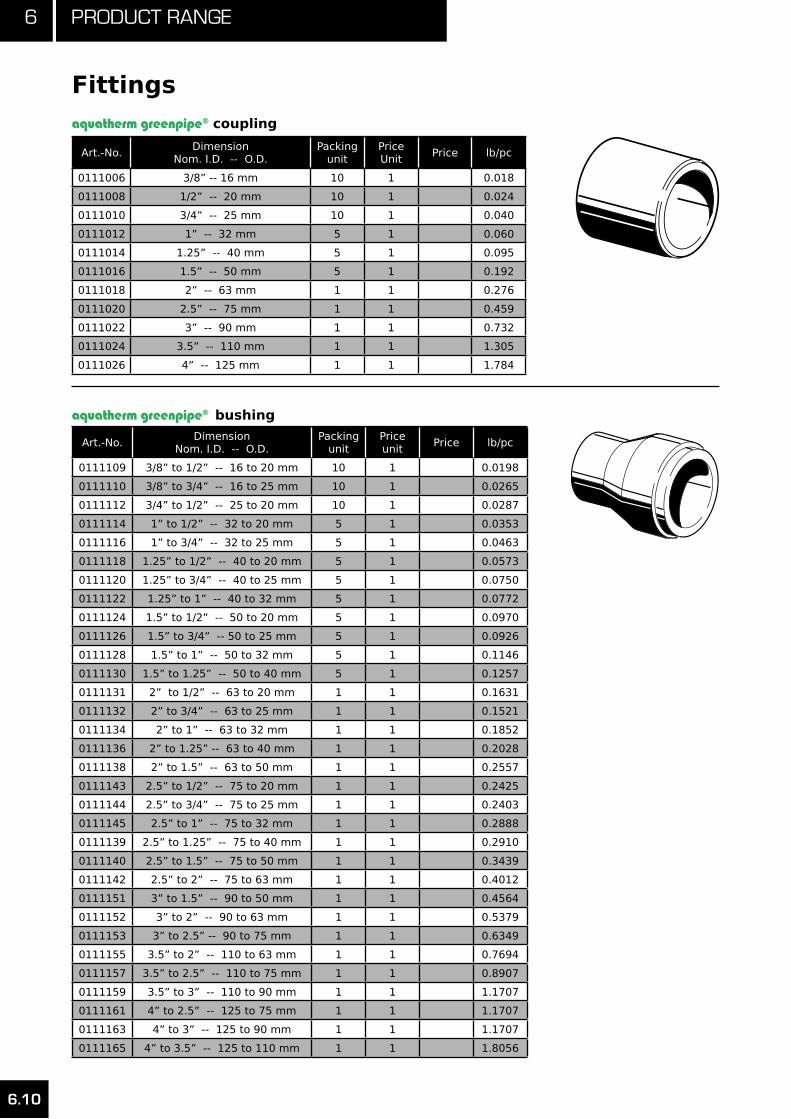
6 Product range
6.10
Fittings
Art.-No.Dimension
Nom. I.D. -- O.D.Packing
unitPrice Unit
Price lb/pc
0111006 3/8” -- 16 mm 10 1 0.018
0111008 1/2” -- 20 mm 10 1 0.024
0111010 3/4” -- 25 mm 10 1 0.040
0111012 1” -- 32 mm 5 1 0.060
0111014 1.25” -- 40 mm 5 1 0.095
0111016 1.5” -- 50 mm 5 1 0.192
0111018 2” -- 63 mm 1 1 0.276
0111020 2.5” -- 75 mm 1 1 0.459
0111022 3” -- 90 mm 1 1 0.732
0111024 3.5” -- 110 mm 1 1 1.305
0111026 4” -- 125 mm 1 1 1.784
11010
Art.-No.Dimension
Nom. I.D. -- O.D.Packing
unitPrice unit
Price lb/pc
0111109 3/8” to 1/2” -- 16 to 20 mm 10 1 0.0198
0111110 3/8” to 3/4” -- 16 to 25 mm 10 1 0.0265
0111112 3/4” to 1/2” -- 25 to 20 mm 10 1 0.0287
0111114 1” to 1/2” -- 32 to 20 mm 5 1 0.0353
0111116 1” to 3/4” -- 32 to 25 mm 5 1 0.0463
0111118 1.25” to 1/2” -- 40 to 20 mm 5 1 0.0573
0111120 1.25” to 3/4” -- 40 to 25 mm 5 1 0.0750
0111122 1.25” to 1” -- 40 to 32 mm 5 1 0.0772
0111124 1.5” to 1/2” -- 50 to 20 mm 5 1 0.0970
0111126 1.5” to 3/4” -- 50 to 25 mm 5 1 0.0926
0111128 1.5” to 1” -- 50 to 32 mm 5 1 0.1146
0111130 1.5” to 1.25” -- 50 to 40 mm 5 1 0.1257
0111131 2” to 1/2” -- 63 to 20 mm 1 1 0.1631
0111132 2” to 3/4” -- 63 to 25 mm 1 1 0.1521
0111134 2” to 1” -- 63 to 32 mm 1 1 0.1852
0111136 2” to 1.25” -- 63 to 40 mm 1 1 0.2028
0111138 2” to 1.5” -- 63 to 50 mm 1 1 0.2557
0111143 2.5” to 1/2” -- 75 to 20 mm 1 1 0.2425
0111144 2.5” to 3/4” -- 75 to 25 mm 1 1 0.2403
0111145 2.5” to 1” -- 75 to 32 mm 1 1 0.2888
0111139 2.5” to 1.25” -- 75 to 40 mm 1 1 0.2910
0111140 2.5” to 1.5” -- 75 to 50 mm 1 1 0.3439
0111142 2.5” to 2” -- 75 to 63 mm 1 1 0.4012
0111151 3” to 1.5” -- 90 to 50 mm 1 1 0.4564
0111152 3” to 2” -- 90 to 63 mm 1 1 0.5379
0111153 3” to 2.5” -- 90 to 75 mm 1 1 0.6349
0111155 3.5” to 2” -- 110 to 63 mm 1 1 0.7694
0111157 3.5” to 2.5” -- 110 to 75 mm 1 1 0.8907
0111159 3.5” to 3” -- 110 to 90 mm 1 1 1.1707
0111161 4” to 2.5” -- 125 to 75 mm 1 1 1.1707
0111163 4” to 3” -- 125 to 90 mm 1 1 1.1707
0111165 4” to 3.5” -- 125 to 110 mm 1 1 1.8056
11134
aquatherm greenpipe® bushing
aquatherm greenpipe® coupling
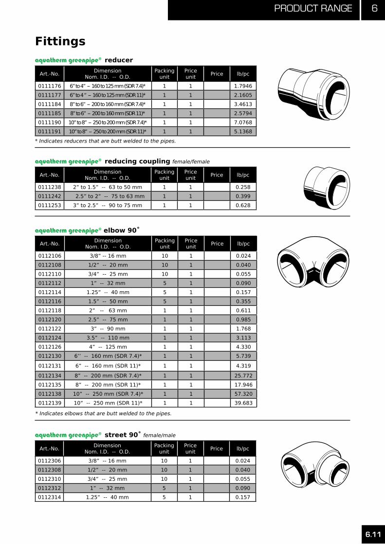
6.11
6Product range
Fittings
Art.-No.Dimension
Nom. I.D. -- O.D.Packing
unitPrice unit
Price lb/pc
0111176 6” to 4” -- 160 to 125 mm (SDR 7.4)* 1 1 1.7946
0111177 6” to 4 “ -- 160 to 125 mm (SDR 11)* 1 1 2.1605
0111184 8” to 6” -- 200 to 160 mm (SDR 7.4)* 1 1 3.4613
0111185 8” to 6” -- 200 to 160 mm (SDR 11)* 1 1 2.5794
0111190 10” to 8” -- 250 to 200 mm (SDR 7.4)* 1 1 7.0768
0111191 10” to 8” -- 250 to 200 mm (SDR 11)* 1 1 5.1368
11134
aquatherm greenpipe® reducer
Art.-No.Dimension
Nom. I.D. -- O.D.Packing
unitPrice unit
Price lb/pc
0111238 2” to 1.5” -- 63 to 50 mm 1 1 0.258
0111242 2.5” to 2” -- 75 to 63 mm 1 1 0.399
0111253 3” to 2.5” -- 90 to 75 mm 1 1 0.628
11238
aquatherm greenpipe® reducing coupling female/female
* Indicates reducers that are butt welded to the pipes.
Art.-No.Dimension
Nom. I.D. -- O.D.Packing
unitPrice unit
Price lb/pc
0112106 3/8” -- 16 mm 10 1 0.024
0112108 1/2” -- 20 mm 10 1 0.040
0112110 3/4” -- 25 mm 10 1 0.055
0112112 1” -- 32 mm 5 1 0.090
0112114 1.25” -- 40 mm 5 1 0.157
0112116 1.5” -- 50 mm 5 1 0.355
0112118 2” -- 63 mm 1 1 0.611
0112120 2.5” -- 75 mm 1 1 0.985
0112122 3” -- 90 mm 1 1 1.768
0112124 3.5” -- 110 mm 1 1 3.113
0112126 4” -- 125 mm 1 1 4.330
0112130 6’’ -- 160 mm (SDR 7.4)* 1 1 5.739
0112131 6” -- 160 mm (SDR 11)* 1 1 4.319
0112134 8” -- 200 mm (SDR 7.4)* 1 1 25.772
0112135 8” -- 200 mm (SDR 11)* 1 1 17.946
0112138 10” -- 250 mm (SDR 7.4)* 1 1 57.320
0112139 10” -- 250 mm (SDR 11)* 1 1 39.683
aquatherm greenpipe® elbow 90˚
12106
* Indicates elbows that are butt welded to the pipes.
Art.-No.Dimension
Nom. I.D. -- O.D.Packing
unitPrice unit
Price lb/pc
0112306 3/8” -- 16 mm 10 1 0.024
0112308 1/2” -- 20 mm 10 1 0.040
0112310 3/4” -- 25 mm 10 1 0.055
0112312 1” -- 32 mm 5 1 0.090
0112314 1.25” -- 40 mm 5 1 0.157
aquatherm greenpipe® street 90˚ female/male
12308

6 Product range
6.12
Fittings
Art.-No.Dimension
Nom. I.D. -- O.D.Packing
unitPrice unit
Price lb/pc
0112506 3/8” -- 16 mm 10 1 0.020
0112508 1/2” -- 20 mm 10 1 0.031
0112510 3/4” -- 25 mm 10 1 0.042
0112512 1” -- 32 mm 5 1 0.077
0112514 1.25” -- 40 mm 5 1 0.119
0112516 1.5” -- 50 mm 5 1 0.254
0112518 2” -- 63 mm 1 1 0.487
0112520 2.5” -- 75 mm 1 1 0.756
0112522 3” -- 90 mm 1 1 1.230
0112524 3.5” -- 110 mm 1 1 2.194
0112526 4” -- 125 mm 1 1 2.818
0112530 6” -- 160 mm (SDR 7.4)* 1 1 4.184
0112531 6” -- 160 mm (SDR 11)* 1 1 3.034
0112534 8” -- 200 mm (SDR 7.4)* 1 1 18.034
0112535 8” -- 200 mm (SDR 11)* 1 1 12.655
0112538 10” -- 250 mm (SDR 7.4)* 1 1 16.173
0112539 10” -- 250 mm (SDR 11)* 1 1 28.660
* Indicates reducers that are butt welded to the pipes.
aquatherm greenpipe® elbow 45˚
12506
Art.-No.Dimension
Nom. I.D. -- O.D.Packing
unitPrice unit
Price lb/pc
0112708 1/2” -- 20 mm 10 1 0.031
0112710 3/4” -- 25 mm 10 1 0.040
0112712 1” -- 32 mm 5 1 0.079
0112714 1.25” -- 40 mm 5 1 0.126
aquatherm greenpipe® street 45˚ female/male
12708
aquatherm greenpipe® tee
Art.-No.Dimension
Nom. I.D. -- O.D.Packing
unitPrice unit
Price lb/pc
0113106 3/8” -- 16 mm 10 1 0.033
0113108 1/2” -- 20 mm 10 1 0.053
0113110 3/4” -- 25 mm 10 1 0.073
0113112 1” -- 32 mm 5 1 0.134
0113114 1.25” -- 40 mm 5 1 0.196
0113116 1.5” -- 50 mm 5 1 0.452
0113118 2” -- 63 mm 1 1 0.811
0113120 2.5” -- 75 mm 1 1 1.226
0113122 3” -- 90 mm 1 1 2.134
0113124 3.5” -- 110 mm 1 1 3.788
0113126 4” -- 125 mm 1 1 5.889
0113130 6” -- 160 mm (SDR 7.4)* 1 1 8.051
0113131 6” -- 160 mm (SDR 11)* 1 1 6.111
0113134 8” -- 200 mm (SDR 7.4)* 1 1 8.051
0113135 8” -- 200 mm (SDR 11)* 1 1 15.146
0113138 10” -- 250 mm (SDR 7.4)* 1 1 48.502
0113139 10” -- 250 mm (SDR 11)* 1 1 35.274
13108
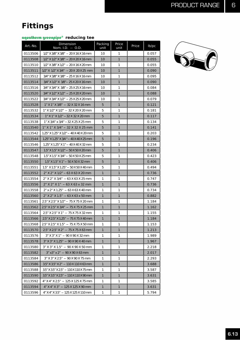
6.13
6Product range
Fittings
Art.-No.Dimension
Nom. I.D. -- O.D.Packing
unitPrice unit
Price lb/pc
0113506 1/2” X 3/8” X 3/8” -- 20 X 16 X 16 mm 10 1 0.057
0113508 1/2” X 1/2” X 3/8” -- 20 X 20 X 16 mm 10 1 0.055
0113510 1/2” X 3/8” X 1/2” -- 20 X 16 X 20 mm 10 1 0.055
0113511 1/2” X 1/2” X 3/4” -- 20 X 20 X 25 mm 10 1 0.090
0113512 3/4” X 3/8” X 3/8” -- 25 X 16 X 16 mm 10 1 0.095
0113514 3/4” X 1/2” X 3/8”-- 25 X 20 X 16 mm 10 1 0.090
0113516 3/4” X 3/4” X 3/8” -- 25 X 25 X 16 mm 10 1 0.084
0113520 3/4” X 1/2” X 1/2” -- 25 X 20 X 20 mm 10 1 0.088
0113522 3/4” X 3/4” X 1/2” -- 25 X 25 X 20 mm 10 1 0.079
0113528 1” X 1” X 3/8” -- 32 X 32 X 16 mm 5 1 0.121
0113532 1” X 1/2” X 1/2” -- 32 X 20 X 20 mm 5 1 0.181
0113534 1” X 1” X 1/2” -- 32 X 32 X 20 mm 5 1 0.117
0113538 1” X 3/4” x 3/4” -- 32 X 25 X 25 mm 5 1 0.134
0113540 1” X 1” X 3/4” -- 32 X 32 X 25 mm 5 1 0.141
0113542 1.25” X 1.25” X 1/2” -- 40 X 40 X 20 mm 5 1 0.203
0113544 1.25” X 1.25” X 3/4 “ -- 40 X 40 X 25 mm 5 1 0.196
0113546 1.25” X 1.25” X 1” -- 40 X 40 X 32 mm 5 1 0.234
0113547 1.5” X 1.5” X 1/2” -- 50 X 50 X 20 mm 5 1 0.406
0113548 1.5” X 1.5” X 3/4” -- 50 X 50 X 25 mm 5 1 0.423
0113550 1.5” X 1.5” X 1” -- 50 X 50 X 32 mm 5 1 0.406
0113551 1.5” X 1.5” X 1.25” -- 50 X 50 X 40 mm 5 1 0.494
0113552 2” X 2” X 1/2” -- 63 X 63 X 20 mm 1 1 0.736
0113554 2” X 2” X 3/4” -- 63 X 63 X 25 mm 1 1 0.747
0113556 2” X 2” X 1” -- 63 X 63 x 32 mm 1 1 0.736
0113558 2” x 2” X 1.25” -- 63 X 63 X 40 mm 1 1 0.734
0113560 2” X 2” X 1.5” -- 63 X 63 x 50 mm 1 1 0.882
0113561 2.5” X 2.5” X 1/2” -- 75 X 75 X 20 mm 1 1 1.184
0113562 2.5” X 2.5” X 3/4” -- 75 X 75 X 25 mm 1 1 1.162
0113564 2.5” X 2.5” X 1” -- 75 X 75 X 32 mm 1 1 1.155
0113566 2.5” X 2.5” X 1.25” -- 75 X 75 X 40 mm 1 1 1.184
0113568 2.5” X 2.5” X 1.5” -- 75 X 75 X 50 mm 1 1 1.153
0113570 2.5” X 2.5” X 2” -- 75 X 75 X 63 mm 1 1 1.213
0113576 3” X 3” X 1” -- 90 X 90 X 32 mm 1 1 1.989
0113578 3” X 3” X 1.25” -- 90 X 90 X 40 mm 1 1 1.967
0113580 3” X 3” X 1.5” -- 90 X 90 X 50 mm 1 1 2.218
0113582 3” x3” x 2” -- 90 X 90 X 63 mm 1 1 2.017
0113584 3’’ X 3” X 2.5” -- 90 X 90 X 75 mm 1 1 2.293
0113586 3.5” X 3.5” X 2” -- 110 X 110 X 63 mm 1 1 3.688
0113588 3.5” X 3.5” X 2.5” -- 110 X 110 X 75 mm 1 1 3.587
0113590 3.5” X 3.5” X 2.5” -- 110 X 110 X 90 mm 1 1 3.631
0113592 4” X 4” X 2.5” -- 125 X 125 X 75 mm 1 1 3.585
0113594 4” X 4” X 3” -- 125 X 125 X 90 mm 1 1 3.631
0113596 4” X 4” X 3.5” -- 125 X 125 X 110 mm 1 1 5.794
aquatherm greenpipe® reducing tee
13550
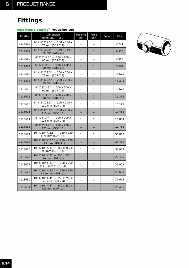
6 Product range
6.14
Fittings
Art.-No.Dimension
Nom. I.D. -- O.D.Packing
unitPrice unit
Price lb/pc
01136006” X 6” X 2.5” -- 160 x 160 x
75 mm (SDR 7.4)1 1 9.731
01136016” X 6” X 2.5” -- 160 x 160 x
75 mm (SDR 11)1 1 6.923
01136026” X 6” X 3” -- 160 x 160 x
90 mm (SDR 7.4)1 1 9.954
01136036” X 6” X 3” -- 160 x 160 x
90 mm (SDR 11)1 1 7.002
01136088” X 8” X 2.5” -- 200 x 200 x
75 mm (SDR 7.4)1 1 15.675
01136098” X 8” X 2.5” -- 200 x 200 x
75 mm (SDR 11)1 1 11.649
01136108” X 8” X 3” -- 200 x 200 x
90 mm (SDR 7.4)1 1 16.623
01136118” X 8” X 3” -- 200 x 200 x
90 mm (SDR 11)1 1 11.393
01136128” X 8” X 3.5” -- 200 x 200 x
110 mm (SDR 7.4)1 1 16.149
01136138” X 8” X 3.5” -- 200 x 200 x
110 mm (SDR 11)1 1 12.452
01136148” X 8” X 4” -- 200 x 200 x
125 mm (SDR 7.4)1 1 16.854
01136158” X 8” X 4” -- 200 x 200 x
125 mm (SDR 11)1 1 12.756
011362410” X 10” X 2.5” -- 250 x 250
x 75 mm (SDR 7.4)1 1 36.850
011362510” X 10” X 2.5” -- 250 x 250
x 75 mm (SDR 11)1 1 26.455
011362610” X 10” X 3” -- 250 x 250 x
90 mm (SDR 7.4)1 1 37.002
011362710” X 10” X 3” -- 250 x 250 x
90 mm (SDR 11)1 1 26.455
011362810” X 10” X 3.5” -- 250 x 250
x 110 mm (SDR 7.4)1 1 37.002
011362910” X 10” X 3.5” -- 250 x 250
x 110 mm (SDR 11)1 1 28.660
011363010” X 10” X 4” -- 250 x 250 x
125 mm (SDR 7.4)1 1 37.615
011363110” X 10” X 4” -- 250 x 250 x
125 mm (SDR 11)1 1 26.455
aquatherm greenpipe® reducing tee
13550

6.15
6Product range
Fittings
Art.-No.Dimension
Nom. I.D. -- O.D.Packing
unitPrice unit
Price lb/pc
0114106 3/8” -- 16 mm 10 1 0.020
0114108 1/2” -- 20 mm 10 1 0.024
0114110 3/4” -- 25 mm 10 1 0.020
0114112 1” -- 32 mm 5 1 0.051
0114114 1.25” -- 40 mm 5 1 0.093
0114116 1.5” -- 50 mm 5 1 0.174
0114118 2” -- 63 mm 1 1 0.320
0114120 2.5” -- 75 mm 1 1 0.529
0114122 3” -- 90 mm 1 1 0.836
0114124 3.5” -- 110 mm 1 1 1.360
0114126 4” -- 125 mm 1 1 1.889
0114130 6” -- 160 mm (SDR 7.4) 1 1 1.889
0114131 6” -- 160 mm (SDR 11) 1 1 1.658
0114134 8” -- 200 mm (SDR 7.4) 1 1 3.064
0114135 8” -- 200 mm (SDR 11) 1 1 2.205
0114138 10” -- 250 mm (SDR 7.4) 1 1 5.622
0114139 10” -- 250 mm (SDR 11) 1 1 4.431
aquatherm greenpipe® end cap
14108
Art.-No.Dimension
Nom. I.D. -- O.D.Packing
unitPrice unit
Price lb/pc
0116106 3/8” -- 16 mm 10 1 0.086
0116108 1/2” -- 20 mm 10 1 0.143
0116110 3/4” -- 25 mm 10 1 0.212
0116112 1” -- 32 mm 5 1 0.340
aquatherm greenpipe® cross-over
16108
Art.-No.Dimension
Nom. I.D. -- O.D.Packing
unitPrice unit
Price lb/pc
0113708 1/2” -- 20 mm 10 1 0.057
0113710 3/4” -- 25 mm 10 1 0.079
0113712 1” -- 32 mm 5 1 0.148
0113714 1.25” -- 40 mm 5 1 0.231
aquatherm greenpipe® cross13708
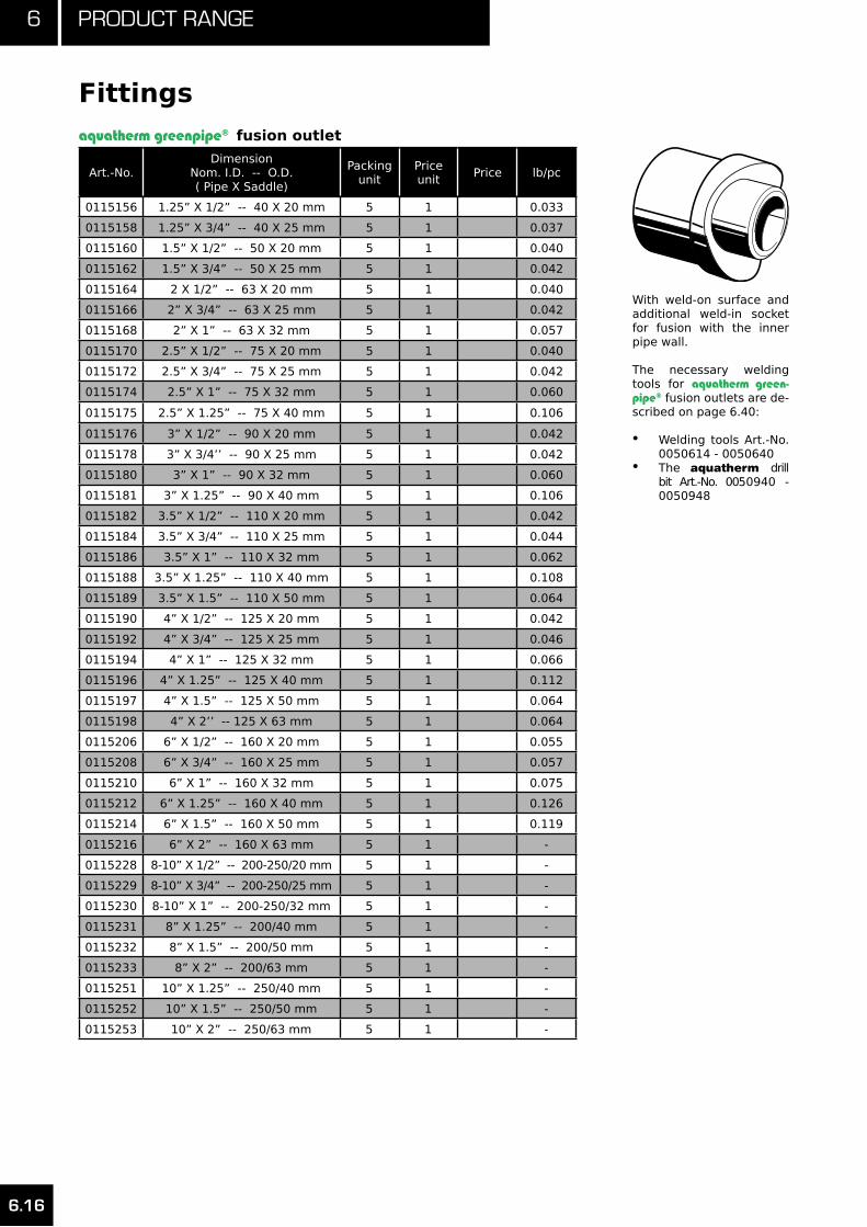
6 Product range
6.16
Fittings
Art.-No.Dimension
Nom. I.D. -- O.D. ( Pipe X Saddle)
Packing unit
Price unit
Price lb/pc
0115156 1.25” X 1/2” -- 40 X 20 mm 5 1 0.033
0115158 1.25” X 3/4” -- 40 X 25 mm 5 1 0.037
0115160 1.5” X 1/2” -- 50 X 20 mm 5 1 0.040
0115162 1.5” X 3/4” -- 50 X 25 mm 5 1 0.042
0115164 2 X 1/2” -- 63 X 20 mm 5 1 0.040
0115166 2” X 3/4” -- 63 X 25 mm 5 1 0.042
0115168 2” X 1” -- 63 X 32 mm 5 1 0.057
0115170 2.5” X 1/2” -- 75 X 20 mm 5 1 0.040
0115172 2.5” X 3/4” -- 75 X 25 mm 5 1 0.042
0115174 2.5” X 1” -- 75 X 32 mm 5 1 0.060
0115175 2.5” X 1.25” -- 75 X 40 mm 5 1 0.106
0115176 3” X 1/2” -- 90 X 20 mm 5 1 0.042
0115178 3” X 3/4’’ -- 90 X 25 mm 5 1 0.042
0115180 3” X 1” -- 90 X 32 mm 5 1 0.060
0115181 3” X 1.25” -- 90 X 40 mm 5 1 0.106
0115182 3.5” X 1/2” -- 110 X 20 mm 5 1 0.042
0115184 3.5” X 3/4” -- 110 X 25 mm 5 1 0.044
0115186 3.5” X 1” -- 110 X 32 mm 5 1 0.062
0115188 3.5” X 1.25” -- 110 X 40 mm 5 1 0.108
0115189 3.5” X 1.5” -- 110 X 50 mm 5 1 0.064
0115190 4” X 1/2” -- 125 X 20 mm 5 1 0.042
0115192 4” X 3/4” -- 125 X 25 mm 5 1 0.046
0115194 4” X 1” -- 125 X 32 mm 5 1 0.066
0115196 4” X 1.25” -- 125 X 40 mm 5 1 0.112
0115197 4” X 1.5” -- 125 X 50 mm 5 1 0.064
0115198 4” X 2’’ -- 125 X 63 mm 5 1 0.064
0115206 6” X 1/2” -- 160 X 20 mm 5 1 0.055
0115208 6” X 3/4” -- 160 X 25 mm 5 1 0.057
0115210 6” X 1” -- 160 X 32 mm 5 1 0.075
0115212 6” X 1.25” -- 160 X 40 mm 5 1 0.126
0115214 6” X 1.5” -- 160 X 50 mm 5 1 0.119
0115216 6” X 2” -- 160 X 63 mm 5 1 -
0115228 8-10” X 1/2” -- 200-250/20 mm 5 1 -
0115229 8-10” X 3/4” -- 200-250/25 mm 5 1 -
0115230 8-10” X 1” -- 200-250/32 mm 5 1 -
0115231 8” X 1.25” -- 200/40 mm 5 1 -
0115232 8” X 1.5” -- 200/50 mm 5 1 -
0115233 8” X 2” -- 200/63 mm 5 1 -
0115251 10” X 1.25” -- 250/40 mm 5 1 -
0115252 10” X 1.5” -- 250/50 mm 5 1 -
0115253 10” X 2” -- 250/63 mm 5 1 -
aquatherm greenpipe® fusion outlet
With weld-on surface and additional weld-in socket for fusion with the inner pipe wall.
The necessary welding tools for aquatherm green-pipe® fusion outlets are de-scribed on page 6.40:
Welding tools Art.-No. •0050614 - 0050640The• aquatherm drill bit Art.-No. 0050940 - 0050948

6.17
6Product range
Flanges
aquathermDimension
Nom. ID. -- O.D.
nominal flange size
Flange adapterFlange ring
American bolt patternFlange ring
European bolt pattern
Art. No. lb/pc Art. No.Number of bolt holes
lb/pc Art. No. lb/pc
1" -- 32 mm 1.25” 0115512 0.068 3315712 4 2.73 0115712 1.010
1.25" -- 40 mm 1.5” 0115514 0.097 3315714 4 2.73 0115714 1.561
1.5" -- 50 mm 1.5” 0115516 0.134 3315716 4 3.52 0115716 1.715
2" -- 63 mm 2” 0115518 0.220 3315718 4 4.42 0115718 2.006
2.5" -- 75 mm 2.5” 0115520 0.315 3315720 4 7.22 0115720 2.557
3" -- 90 mm 3” 0115522 0.556 3315722 4 8.32 0115722 3.064
3.5" -- 110 mm 3.5” 0115524 0.721 - - - 0115724 3.289
4" -- 125 mm 4” 0115527 2.888 See Table Below 0115726 3.289
4” -- 125 mm 6” 0115527 2.888 3315730 8 15.14 - -
6" -- 160 mm SDR 7.4 6” 0115530 2.564 3315730 8 15.14 0115730 7.998
6" -- 160 mm SDR 11 6” 0115531 2.103 3315730 8 15.14 0115730 7.998
8" -- 200 mm SDR 7.4 8” 0115534 4.409 3315734 8 22.79 0115734 10.472
8" -- 200 mm SDR 11 8” 0115535 4.409 3315734 8 22.79 0115734 10.472
10" -- 250 mm SDR 7.4 10” 0115538 4.409 3315738 12 33.20 0115738 15.644
10" -- 250 mm SDR 11 10” 0115539 4.409 3315738 12 33.20 0115738 15.644
15512
All flange adaptors and flange rings are sold separately and in a single packing unit.15512
aquathermDimension
Nom. ID. -- O.D.
nominal flange size
Flange adapterconnects to coupling
Flange ringAmerican bolt pattern
Art. No. lb/pc Art. No.Number of bolt holes
lb/pc
4” -- 125 mm 4” 0115526 0.068 3315726 8 11.22
11010
Art-No. 0115526 (pictured left) must be paired with a coupling Art.-No 0111026 (pictured above, sold separately)
Art.-No.Dimension
Nom. I.D. -- O.D.Packing
unitPrice unit
Price lb/pc
5515172 3/4” x 1” -- 25 x 32 mm 1 1 -
5515714 1.25” x 1” -- 40 x 32 mm 1 1 -
aquatherm greenpipe® pump flange adapter ring American bolt pattern
aquatherm greenpipe® flange adapter aquatherm flange ring
Art.-No. 5515714 was designed to be compatible with Grundfos Pump Model UP395 and and may or may not be fully compatible with other models.

6 Product range
6.18
Couplings
Art.-No.Dimension
Nom. I.D. -- O.D.Packing
unitPrice unit
Price lb/pc
0115812 1” -- 32 mm 1 1 1.098
0115814 1.25” -- 40 mm 1 1 1.856
0115816 1.5” -- 50 mm 1 1 2.083
0115818 2” -- 63 mm 1 1 3.397
0115820 2.5” -- 75 mm 1 1 4.497
aquatherm greenpipe® union with brass nut
Brass coupling screw with two PP-R flange adapters including washer.
Art.-No.Dimension
Nom. I.D. -- O.D.Packing
unitPrice unit
Price lb/pc
0115838 1/2” -- 20 mm 10 1 0.079
0115840 3/4” -- 25 mm 10 1 0.130
0115842 1” -- 32 mm 5 1 0.194
0115844 1.25” -- 40 mm 5 1 0.295
0115846 1.5” -- 50 mm 5 1 0.373
0115848 2” -- 63 mm 1 1 0.644
0115850 2.5” -- 75 mm 1 1 -
aquatherm greenpipe® union with PP-R nut
Art.-No.Dimension
Nom. I.D. -- O.D.Packing
unitPrice unit
Price lb/pc
0117208 1/2” -- 20 mm 1 1 0.097
0117210 3/4” -- 25 mm 1 1 0.117
0117212 1” -- 32 mm 1 1 0.159
0117214 1.25” -- 40 mm 1 1 0.216
0117216 1.5” -- 50 mm 1 1 0.306
0117218 2” -- 63 mm 1 1 0.496
0117220 2.5” -- 75 mm 1 1 0.754
0117222 3” -- 90 mm 1 1 1.089
0117224 3.5” -- 110 mm 1 1 1.797
0117226 4” -- 125 mm 1 1 2.410
0117230 6” -- 160 mm 1 1 3.900
aquatherm greenpipe® electrofusion socket
Tool:aquatherm greenpipe® electrofusion device (Art.-No. 50175)
aquatherm greenpipe® peeling tool(Art.-No. 0050558 - 0050580)required

6.19
6Product range
Mounting Devices
Sound insulation plate for aquatherm greenpipe® back plate elbow
Art.-No. Dimension Packing
unitPrice unit
Price lb/pc
0079080 2 1 0.249
including two screws each
60010
Art.-No. Dimension Packing
unitPrice unit
Price lb/pc
00600108.7/5.9/3.2 in
220/150/80 mm1 1 0.487
Mounting plate galvanized; to fix back plate elbows as double connection
not suitable for connection with sound insulation plate (Art.-No. 0079080)
50408
Art.-No. Dimension Packing
unitPrice unit
Price lb/pc
0079090 length = 22” -- 560 mm 1 1 1.162
Mounting rail galvanized; to fix back plate elbows including 2 fixing plates and 4 screws
not suitable for connection with sound insulation plate (Art.-No. 0079080)
Mounting Rail (double and single)
Art.-No. Dimension Packing
unitPrice unit
Price lb/pc
0079095 double 2 1 0.908
0079096 single 2 1 -
galvanized, for fixing of back plate elbows
aquatherm greenpipe® back plate elbow threaded
Brass Art.-No.(NPT)
Stainless Steel
Art.-No.(ISO)
Dimension Packing
unitPrice unit
lb/pc
0120106 - (3/8” -- 16 mm) X 1/2” F 10 1 0.187
0120108 920108 (1/2” -- 20 mm) X 1/2” F 10 1 0.187
0120110 920110 (1/2” -- 20 mm) X 3/4” F 10 1 0.245
0120112 920112 (3/4” -- 25 mm) X 3/4” F 10 1 0.245
0120113 920113 (3/4” -- 25 mm) X 1/2” F 10 1 0.201
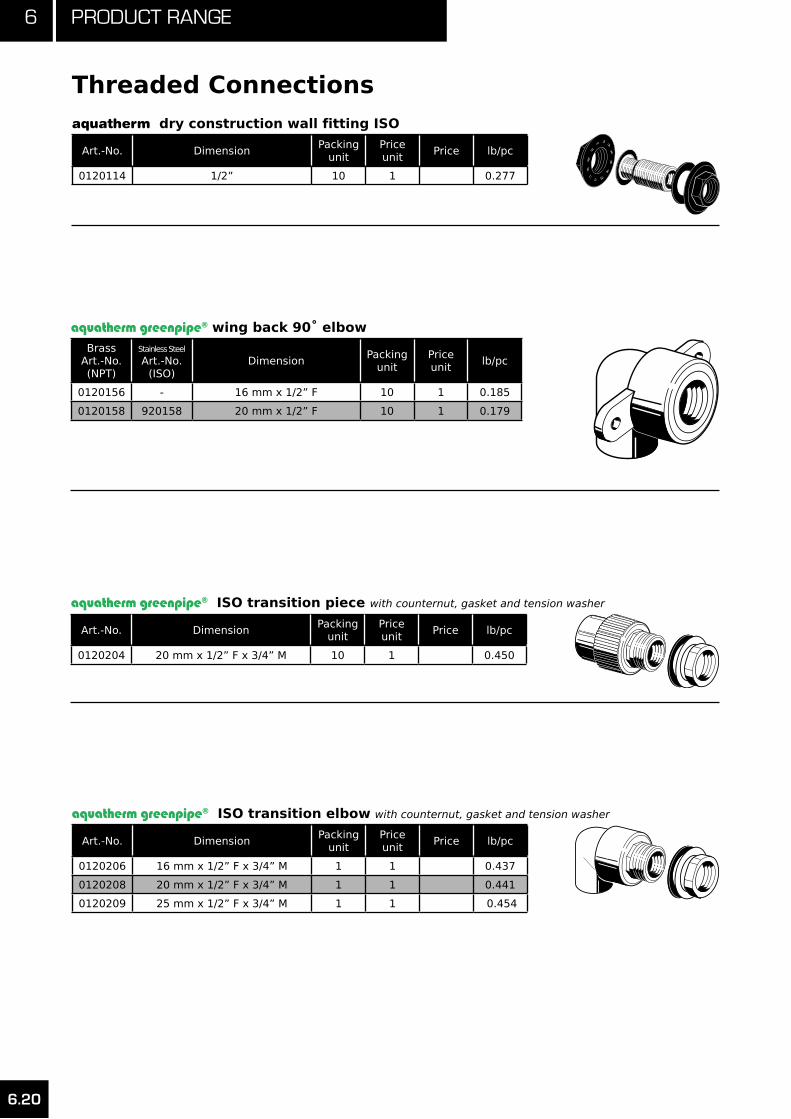
6 Product range
6.20
Threaded Connections20114
Art.-No. Dimension Packing
unitPrice unit
Price lb/pc
0120114 1/2” 10 1 0.277
aquatherm dry construction wall fitting ISO
20158
Brass Art.-No.(NPT)
Stainless Steel
Art.-No.(ISO)
Dimension Packing
unitPrice unit
lb/pc
0120156 - 16 mm x 1/2” F 10 1 0.185
0120158 920158 20 mm x 1/2” F 10 1 0.179
aquatherm greenpipe® wing back 90˚ elbow
20202
Art.-No. Dimension Packing
unitPrice unit
Price lb/pc
0120204 20 mm x 1/2” F x 3/4” M 10 1 0.450
aquatherm greenpipe® ISO transition piece with counternut, gasket and tension washer
20208
aquatherm greenpipe® ISO transition elbow with counternut, gasket and tension washer
Art.-No. Dimension Packing
unitPrice unit
Price lb/pc
0120206 16 mm x 1/2” F x 3/4” M 1 1 0.437
0120208 20 mm x 1/2” F x 3/4” M 1 1 0.441
0120209 25 mm x 1/2” F x 3/4” M 1 1 0.454

6.21
6Product range
Threaded Connections
aquatherm greenpipe® ISO plug for pressure tests with gasket
50708
Art.-No. Dimension Packing
unitPrice unit
Price lb/pc
0050708 1/2” M 1 1 0.046
0050710 3/4” M 1 1 0.059
aquatherm assembling jig
Art.-No. Dimension Packing
unitPrice unit
Price lb/pc
0050700 - 1 1 -
50700
8 0 1 0 0 1 5 0 2 0 0 2 5 0
aquatherm
2 5 0 2 0 0 1 5 0 1 0 0 8 0
60110
80
100
150
Mounting unit twin
Art.-No. Dimension Packing
unitPrice unit
Price lb/pc
00601103.2/4/5.9 in
80/100/150 mm1 1 1.415
Mounting unit single
Art.-No. Dimension Packing
unitPrice unit
Price lb/pc
0060115 - 1 1 0.606

6 Product range
6.22
Threaded Connections
aquatherm greenpipe® ISO transition elbow for dry construction
Art.-No. Dimension Packing
unitPrice unit
Price lb/pc
0120210 20 mm x 1/2” F x 3/4” M 10 1 0.487
20210
with 30 mm thread, counternut, gasket and tension washer
60150
80
100
150
Mounting unit with aquatherm greenpipe® ISO transition elbow (Art.-No. 20208)
Art.-No. Dimension Packing
unitPrice unit
Price lb/pc
0060150 - 1 1 2.301
with counternut, gasket and tension washer
Mounting unit with 1 aquatherm greenpipe® ISO transition elbow (Art.-No. 0120208)
Art.-No. Dimension Packing
unitPrice unit
Price lb/pc
0060155 - 1 1 1.166
with counternut, gasket and tension washer
60155

6.23
6Product range
Transition Pieces21008
Brass Art.-No.(NPT)
Stainless Steel
Art.-No.(ISO)
Dimension Pipe (Nom. I.D. -- O.D.) X
Thread Type
Packing unit
Price unit
lb/pc
0121006 - (3/8” -- 16mm) X 1/2” F 10 1 0.156
0121008 921008 (1/2” -- 20mm) X 1/2” F 10 1 0.154
0121010 921010 (1/2” -- 20mm) X 3/4” F 10 1 0.198
0121011 921011 (3/4” -- 25mm) X 1/2” F 10 1 0.156
0121012 921012 (3/4” -- 25mm) X 3/4” F 10 1 0.189
0121013 921013 (1” -- 32mm) X 3/4” F 5 1 0.205
aquatherm greenpipe® transition piece round
Brass Art.-No.(NPT)
Stainless Steel
Art.-No.(NPT)
Dimension Pipe (Nom. I.D. -- O.D.) X
Thread Type
Packing unit
Price unit
lb/pc
0121106 - (3/8” -- 16 mm) X 1/2” F 10 1 0.192
0121108 - (1/2” -- 20 mm) X 1/2” F 10 1 0.192
0121110 - (1/2” -- 20 mm) X 3/4” F 10 1 0.249
0121111 - (3/4” -- 25 mm) X 1/2” F 10 1 0.192
0121112 - (3/4” -- 25 mm) X 3/4” F 10 1 0.245
0121113 - (1” -- 32 mm) X 3/4” F 5 1 0.251
0121114 1121114 (1” -- 32 mm) X 1” F 5 1 0.527
0121115 1121115 (1.25” -- 40 mm) X 1” F 5 1 0.542
0121116 1121116 (1.25” -- 40 mm) X 1.25” F 5 1 0.844
0121117 1121117 (1.5” -- 50 mm) X 1.25” F 5 1 0.884
0121118 1121118 (1.5” -- 50 mm) X 1.5” F 5 1 0.981
0121119 1121119 (2” -- 63 mm) X 1.5” F 1 1 1.032
0121120 - (2” -- 63 mm) X 2” F 1 1 1.433
0121122 - (2.5” -- 75 mm) X 2” F 1 1 1.479
aquatherm greenpipe® NPT transition piece with hex-shaped threaded transition
21108
Brass Art.-No.(NPT)
Stainless Steel
Art.-No.(ISO)
Dimension Pipe (Nom. I.D. -- O.D.) X
Thread Type
Packing unit
Price unit
lb/pc
0121206 - (3/8” -- 16mm) X 1/2” M 10 1 0.216
0121208 921208 (1/2” -- 20mm) X 1/2” M 10 1 0.212
0121210 921210 (1/2” -- 20mm) X 3/4” M 10 1 0.238
0121211 921211 (3/4” -- 25mm) x 1/2” M 10 1 0.218
0121212 921212 (3/4” -- 25mm) X 3/4” M 10 1 0.238
0121213 921213 (1” -- 32mm) X 3/4” M 5 1 0.249
aquatherm greenpipe® transition piece round
21208

6 Product range
6.24
Transition Pieces
Art.-No.Dimension
Pipe (Nom. I.D. -- O.D.) X Thread Type
Packing unit
Price unit
Price lb/pc
0121306 (3/8” -- 16mm) X 1/2” M 10 1 0.265
0121308 (1/2’’ -- 20mm) X 1/2” M 10 1 0.260
0121310 (1/2” -- 20mm) X 3/4”M 10 1 0.284
0121312 (3/4” -- 25mm) X 3/4” M 10 1 0.282
0121314 (1” -- 32mm) X 1”M 5 1 0.538
0121316 (1” -- 32mm) X 1.25” M 5 1 0.787
0121317 (1.25” -- 40mm) X 1” M 5 1 0.551
0121318 (1.25” -- 40mm) X 1.25” M 5 1 0.802
0121319 (1.5” -- 50mm) x 1.25” M 5 1 0.862
0121320 (1.5” -- 50mm) X 1.5” M 5 1 1.058
0121321 (2” -- 63mm) X 1.5” M 1 1 1.153
0121322 (2” -- 63mm) x 2” M 1 1 1.554
0121323 (2.5” -- 75mm) X 2” M 1 1 1.660
0121324 (2.5” -- 75mm) X 2.5” M 1 1 2.258
0121325 (3” -- 90mm) X 3” M 1 1 3.373
0121327 (3.5” -- 110mm) X 4” M 1 1 6.208
aquatherm greenpipe® NPT transition piece hex-shaped threaded transition
21308
Brass Art.-No.(NPT)
Stainless Steel
Art.-No.(ISO)
Dimension Packing
unitPrice unit
lb/pc
0123006 - (3/8” -- 16mm) X 1/2” F 10 1 0.181
0123008 923008 (1/2” -- 20mm) X 3/4” F 10 1 0.238
0123010 923010 (1/2” -- 20mm) X 1/2” F 10 1 0.179
0123012 923012 (3/4” -- 25mm) X 3/4” F 10 1 0.234
0123014 923014 (3/4” -- 25mm) X 1/2” F 10 1 0.192
0123016 923016 (1” -- 32mm) X 3/4” F 5 1 0.243
(NPT)
0123018 1123018 (1” -- 32mm) X 1” F 5 1 0.573
aquatherm greenpipe® transition elbow
23008
Art.-No. Dimension Packing
unitPrice unit
Price lb/pc
0123208 (1/2” -- 20mm) X 1/2” F 10 1 0.176
aquatherm greenpipe® NPT transition elbow (male/female)
23208

6.25
6Product range
Transition Pieces
Brass Art.-No.(NPT)
Stainless Steel
Art.-No.(ISO)
Dimension Packing
unitPrice unit
lb/pc
0123504 - (3/8” -- 16mm) X 1/2” M 10 1 0.236
0123506 923506 (1/2” -- 20mm) X 1/2” M 10 1 0.240
0123508 923508 (1/2” -- 20mm) X 3/4” M 10 1 0.282
0123510 923510 (3/4” -- 25mm) X 3/4” M 10 1 0.273
0123512 923512 (1” -- 32mm) X 3/4” M 5 1 0.293
0123514 - (1” -- 32mm) X 1” M 5 1 0.573
aquatherm greenpipe® transition elbow (male)
23508
Brass Art.-No.(NPT)
Stainless Steel
Art.-No.(ISO)
Dimension Packing
unitPrice unit
lb/pc
0125004 -(3/8” -- 16mm) X (3/8” --
16mm) X 1/2” F10 1 0.198
0125006 925006(1/2” -- 20mm) X (1/2” --
20mm) X 1/2” F10 1 0.194
0125008 925008(1/2” -- 20mm) X (1/2” --
20mm) X 3/4” F10 1 0.265
0125010 925010(3/4” -- 25mm) X (3/4” --
25mm) X 1/2” F10 1 0.205
0125012 925012(3/4” -- 25mm) X (3/4” --
25mm) X 3/4” F10 1 0.256
0125014 925014(1” -- 32mm) X (1” -- 32mm)
X 3/4” F5 1 0.260
(NPT)
0125016 1125016(1” -- 32mm) X (1” -- 32mm)
X 1” F5 1 0.600
0125022 -(1.5” -- 50 mm) X (1.5” -- 50
mm) X 1” F5 1 -
aquatherm greenpipe® transition tee (female)
25006
Art.-No. Dimension Packing
unitPrice unit
Price lb/pc
0125506(1/2” -- 20mm) X 1/2” M
X (1/2” -- 20mm)10 1 0.254
aquatherm greenpipe® NPT transition tee (male)
25506
Art.-No. Dimension Packing
unitPrice unit
Price lb/pc
0126708 1/2” - 20 mm / nut G 1” 1 1 0.182
0126710 3/4” -- 25 mm / nut G 1 1/4” 1 1 0.257
0126712 7/8”-- 30 mm / nut G 1 1/2” 1 1 0.352
0126714 1.25”--40 mm / nut G 2” 1 1 0.564
0126716 1.5”--50 mm / nut G 2 1/4” 1 1 0.961
0126718 2” -- 63 mm / nut G 2 3/4” 1 1 1.192
0126720 2.5” -- 75 mm / nut G 3 1/2” 1 1 2.023
0126722 3” -- 90 mm / nut G 4” 1 1 2.729
aquatherm greenpipe® ISO pump adapter with joint ring length: 100 mm

6 Product range
6.26
Transition Pieces
Art.-No. Dimension Packing
unitPrice unit
Price lb/pc
01990311/2” (20 mm) PPR to
3/8” Compression5 1 2.204
aquatherm greenpipe® transition to compression fitting (PP-R to Brass)
Art.-No. Dimension Packing
unitPrice unit
Price lb/pc
0126808(1/2” -- 20mm) X
nut G 3/4”1 1 0.332
0126810(3/4” -- 25mm) X
nut G 3/4”1 1 0.332
0126812(1” -- 32mm) X
nut G 3/4”1 1 0.357
aquatherm greenpipe® ISO water meter connecting union with gasket
26810
aquatherm greenpipe® transition joint ISO-Standard
Art.-No. Dimension Packing
unitPrice unit
Price lb/pc
0127010 (1/2” -- 20mm) X nut G 1” 10 1 0.401
0127011 (3/4” -- 25mm) X nut G 1” 10 1 0.407
0127012 (3/4” -- 25mm) X nut G 1.25” 10 1 0.557
0127013 (1” -- 32mm) X nut G 1.25” 5 1 0.599
0127014 (1” -- 32mm) X nut G 1.5” 5 1 0.963
0127015 (1.25” -- 40mm) X nut G 1.5” 5 1 0.996
0127016 (1.25” -- 40mm) X nut G 2” 5 1 1.554
0127017 (2” -- 50mm) X nut G 2” 5 1 1.593
0127018 (2” -- 50mm) X nut G 2.25” 5 1 2.026
0127019 (2” -- 63mm) X nut G 2.25” 1 1 2.096
0127020 (2” -- 63mm) X nut G 2.75” 1 1 2.724
0127021 (2.5” -- 75mm) X nut G 2.75” 1 1 2.777
0127022 (2.5” -- 75mm) X nut G 3.5” 1 1 4.038
27010
Art.-No. Dimension Packing
unitPrice unit
Price lb/pc
0127310 (1/2” -- 20mm) X 1” M 10 1 0.328
0127311 (3/4” -- 25mm) X 1” M 10 1 0.330
0127312 (3/4” -- 25 mm) X 1.25”M 10 1 0.489
0127313 (1” -- 32 mm) X 1.25” M 5 1 0.498
0127314 (1” -- 32 mm) X 1.5” M 5 1 0.890
0127315 (1.25” -- 40 mm) X 1.5”M 5 1 0.901
0127316 (1.25” -- 40 mm) X 2” M 5 1 1.331
0127317 (1.5” -- 50 mm) X 2” M 5 1 1.388
0127318 (1.5” -- 50 mm) X 2.25” M 5 1 1.466
0127319 (2” -- 63 mm) X 2.25” M 1 1 1.530
0127320 (2” -- 63 mm) X 2.75” M 1 1 2.361
0127321 (2.5” -- 75 mm) X 2.75” M 1 1 2.414
0127322 (2.5” -- 75 mm) X 3.5” M 1 1 3.179
aquatherm greenpipe® counterpart with welding socket and male thread for ISO-threaded joints
27310

6.27
6Product range
Transition Pieces
Art.-No. Dimension Packing
unitPrice unit
Price lb/pc
0127510 1” M X 1/2” F 10 1 0.138
0127512 1.25” M X 3/4” F 10 1 0.264
0127514 1.5” M X 1” F 5 1 0.381
0127516 2” M X 1.25” F 5 1 0.566
0127518 2.25” M X 1.5” F 5 1 0.738
0127520 2.75” M X 2” F 1 1 1.119
0127522 3.5” M X 2.5” F 1 1 1.781
0127524 4” M X 3” F 1 1 2.085
Brass counterpart with female thread, for ISO-threaded joints / threaded connection
27510
Brass counterpart with male thread, for ISO-threaded joints / threaded connection
Art.-No. Dimension Packing
unitPrice unit
Price lb/pc
0127710 1/2” M X 1” M 10 1 0.238
0127712 3/4” M X 1.25” M 10 1 0.418
0127714 1” M X 1.5” M 5 1 0.546
0127716 1.25” M X 2” M 5 1 0.974
0127718 1.5” M X 2.25” M 5 1 1.038
0127720 2” M X 2.75” M 1 1 1.781
0127722 2.5” M X 3.5” M 1 1 2.742
0127724 3” M X 4” M 1 1 3.095
27712

6 Product range
6.28
Transition Pieces
Brass Art.-No.(NPT)
Stainless Steel
Art.-No.(ISO)
Dimension Packing
unitPrice unit
lb/pc
0128214 928214 1.25” / 3/4” -- 40 / 25 mm - 1/2” F 5 1 0.192
0128216 928216 1.5” / 3/4” -- 50 / 25 mm - 1/2” F 5 1 0.194
0128218 928218 2” / 3/4” -- 63 / 25 mm - 1/2” F 5 1 0.194
0128220 928220 2.5” / 3/4” -- 75 / 25 mm - 1/2” F 5 1 0.194
0128222 928222 3” / 3/4” -- 90 / 25 mm - 1/2” F 5 1 0.194
0128224 928224 3.5” / 3/4” -- 110 / 25 mm - 1/2” F 5 1 0.194
0128226 928226 4” / 3/4”” -- 125 / 25 mm - 1/2” F 5 1 0.201
0128230 928230 6” / 3/4” -- 160 / 25 mm - 1/2” F 5 1 0.209
0128232 928232 8 - 10” / 3/4” -- 200 - 250 / 25 mm - 1/2” F 5 1 0.238
0128234 928234 1.25” / 3/4” -- 40 / 25 mm - 3/4” F 5 1 0.245
0128236 928236 1.5” / 3/4” -- 50 / 25 mm - 3/4” F 5 1 0.243
0128238 928238 2” / 3/4” -- 63 / 25 mm - 3/4” F 5 1 0.240
0128240 928240 2.5” / 3/4” -- 75 / 25 mm - 3/4” F 5 1 0.243
0128242 928242 3” / 3/4” -- 90 / 25 mm - 3/4” F 5 1 0.245
0128244 928244 3.5” / 3/4” -- 110 / 25 mm - 3/4” F 5 1 0.247
0128246 928246 4” / 3/4” -- 125 / 25 mm - 3/4” F 5 1 0.287
0128250 928250 6” / 3/4” -- 160 / 25 mm - 3/4” F 5 1 0.194
0128254 928254 8 - 10” / 3/4” -- 200 - 250 / 25 mm - 3/4” F 5 1 0.194
(NPT)
0128260 1128260 2.5” / 1” -- 75 / 32 mm - 1” F 5 1 0.522
0128262 1128262 3” / 1” -- 90 / 32 mm - 1” F 5 1 0.522
0128264 1128264 3.5” / 1” -- 110 / 32 mm - 1” F 5 1 0.538
0128266 1128266 4” / 1” -- 125 / 32 mm 1” F 5 1 0.522
0128270 1128270 6” / 1” -- 160 / 32 mm - 1” F 5 1 0.538
0128274 1128274 8 - 10” / 1” -- 200 - 250 / 32 mm - 1” F 5 1 0.538
aquatherm greenpipe® NPT fusion outlet with hex shaped female thread, weld-in surface and weld-in socket for fusion with the inner wall of the pipe
The necessary tools for the fusion of aquatherm green-pipe® fusion outlets are listed on page 6.40
Welding tools for fusion outlets Art. No. 0050614 - 0050640
Brass Art.-No.
Dimension Packing
unitPrice unit
Price lb/pc
0128314 1.25” / 3/4” -- 40 / 25 mm - 1/2” M 5 1 0.192
0128316 1.5” / 3/4” -- 50 / 25 mm - 1/2” M 5 1 0.198
0128318 2” / 3/4” -- 63 / 25 mm - 1/2” M 5 1 0.194
0128320 2.5” / 3/4” -- 75 / 25 mm - 1/2” M 5 1 0.212
0128322 3” / 3/4” -- 90 / 25 mm - 1/2” M 5 1 0.196
0128324 3.5” / 3/4” -- 110 / 25 mm - 1/2” M 5 1 0.196
0128326 4” / 3/4”” -- 125 / 25 mm - 1/2” M 5 1 0.201
0128330 6” / 3/4” -- 160 / 25 mm - 1/2” M 5 1 0.201
0128334 1.25” / 3/4” -- 40 / 25 mm - 3/4” M 5 1 0.236
0128336 1.5” / 3/4” -- 50 / 25 mm - 3/4” M 5 1 0.240
0128338 2” / 3/4” -- 63 / 25 mm - 3/4” M 5 1 0.238
0128340 2.5” / 3/4” -- 75 / 25 mm - 3/4” M 5 1 0.238
0128342 3” / 3/4” -- 90 / 25 mm - 3/4” M 5 1 0.243
0128344 3.5” / 3/4” -- 110 / 25 mm - 3/4” M 5 1 0.240
0128346 4” / 3/4” -- 125 / 25 mm - 3/4” M 5 1 0.245
0128350 6” / 3/4” -- 160 / 25 mm - 3/4” M 5 1 0.245
aquatherm greenpipe® NPT fusion outlet with hex shaped male thread, weld-in surface and weld-in socket for fusion with the inner wall of the pipe

6.29
6Product range
Distributors
Art.-No. Dimension Packing
unitPrice unit
Price lb/pc
0130115 3/4” X 1/2” -- 25 X 20mm 1 1 0.608
aquatherm greenpipe® distribution block plumbing including 1 plug and 2 fastenings
Material: Fusiolen® PP-Rpassage: 25 mm (socket) / 2 branches: 20 mm (sockets)
T-Stück
Art.-No. Dimension Packing
unitPrice unit
Price lb/pc
0130130 3/4” X 1/2” -- 25 X 20mm 1 1 0.696
aquatherm greenpipe® distribution block plumbing with insulation block (3” X 3” -- 70 X 70mm)
Übergangsstück
T-Stück
Material: Fusiolen® PP-R / PPO/PSpassage: 25 mm (socket) / 2 branches: 20 mm (sockets)
Art.-No. Dimension Packing
unitPrice unit
Price lb/pc
0130602 1” X 3/8” -- 32 X 16mm 1 1 0.310
0130604 1” X 1/2” -- 32 X 20mm 1 1 0.295
aquatherm greenpipe® distribution pipe Length: 246 mm, with four branch connections
The distribution pipe can be shortened or supplementedby fusion with further distribution pipes as needed.
30602
Art.-No. Dimension Packing
unitPrice unit
Price lb/pc
0130804 (1” -- 32 mm) X 1/2” F 1 1 0.182
aquatherm greenpipe® distributor end piece with female thread NPT30804
to empty or aerate the distribution pipe

6 Product range
6.30
Valves
aquatherm greenpipe® ball valve (male/female)
Art.-No. Dimension Packing
unitPrice unit
Price lb/pc
0078000 (1” -- 32 mm) M/F 1 1 2.574
Art.-No. Dimension Packing
unitPrice unit
Price lb/pc
0060210 1” -- 32mm 2 1 0.489
Supporting strap for aquatherm distribution pipe galvanized, twin
60210
Art.-No. Dimension Packing
unitPrice unit
Price lb/pc
0140808 1/2” -- 20 mm 1 1 0.452
0140810 3/4” -- 25 mm 1 1 0.465
0140812 1” -- 32 mm 1 1 0.774
0140814 1.25” -- 40 mm 1 1 1.257
aquatherm greenpipe® screw-down stop globe valve for surface installation40808
aquatherm greenpipe® concealed valve chromium-plated
Art.-No. Dimension Packing
unitPrice unit
Price lb/pc
0140858 1/2” -- 20 mm 1 1 0.712
0140860 3/4” -- 25 mm 1 1 0.732
0140862 1” -- 32 mm 1 1 0.915
40858

6.31
6Product range
Valves
Art.-No. Dimension Packing
unitPrice unit
Price lb/pc
0140868 1/2” -- 20 mm 1 1 0.648
0140870 3/4” -- 25 mm 1 1 0.758
0140872 1” -- 32 mm 1 1 0.947
aquatherm greenpipe® concealed valve chromium-plated, tamper proof, short design
Art.-No. 0140868 - 0140870 suitable for construction depths up to 1”Art.-No. 0140872 suitable for construction depths up to 1 1/8”
Art.-No. Dimension Packing
unitPrice unit
Price lb/pc
0140878 1/2” -- 20 mm 1 1 0.787
0140880 3/4” -- 25 mm 1 1 0.816
0140882 1” -- 32 mm 1 1 0.972
aquatherm greenpipe® concealed valve chromium-plated
40878
suitable for construction depths from 2 1/8” - 4”
Art.-No. Dimension Packing
unitPrice unit
Price lb/pc
0140888 1/2” -- 20 mm 1 1 0.728
0140890 3/4” -- 25 mm 1 1 0.752
0140892 1” -- 32 mm 1 1 0.935
aquatherm greenpipe® concealed valve chromium-plated, tamper proof
suitable for construction depths up to 2 1/3”
Extension for aquatherm greenpipe® concealed valve chromium-plated for Art.-No. 0040858 - 0040862
Art.-No. Dimension Packing
unitPrice unit
Price lb/pc
0040900 Length = 3.2” -- 92 mm 1 1 0.302
0040902 Lenght = 4.25” -- 132 mm 1 1 0.447
40900

6 Product range
6.32
Valves
Art.-No. Dimension Packing
unitPrice unit
Price lb/pc
0041108 1/2” -- 20 mm 1 1 0.648
0041110 3/4” -- 25 mm 1 1 0.622
0041112 1” -- 32 mm 1 1 0.933
0041114 1.25” -- 40 mm 1 1 1.836
aquatherm greenpipe® inclined valve without drain
41108
aquatherm greenpipe® combination valve, check valve without drain
Art.-No. Dimension Packing
unitPrice unit
Price lb/pc
0041208 1/2” -- 20 mm 1 1 0.657
0041210 3/4” -- 25 mm 1 1 0.631
0041212 1” -- 32 mm 1 1 0.957
0041214 1.25” -- 40 mm 1 1 1.856
41208
aquatherm greenpipe® ball valve without drain
Art.-No. Dimension Packing
unitPrice unit
Price lb/pc
0041308 1/2” -- 20 mm 1 1 0.617
0041310 3/4” -- 25 mm 1 1 0.818
0041312 1” -- 32 mm 1 1 1.307
0041314 1.25” -- 40 mm 1 1 2.094
0041316 1.5” -- 50 mm 1 1 3.494
0041318 2” -- 63 mm 1 1 5.626
Art.-No. Dimension Packing
unitPrice unit
Price lb/pc
0040908 ( 1/2” -- 20 mm) X 3/4” 1 1 0.234
0040910 ( 3/4” -- 25 mm ) X 3/4” 1 1 0.216
0040912 ( 1” -- 32 mm) X 1” 1 1 0.317
0040914 ( 1.25” -- 40 mm ) X 1.25” 1 1 0.681
aquatherm-greenpipe® stop valve body
40908

6.33
6Product range
Valves
aquatherm greenpipe® ball valve polypropylene
Art.-No. Dimension Packing
unitPrice unit
Price lb/pc
0141388 1/2” -- 20 mm 1 1 0.287
0141390 3/4” -- 25 mm 1 1 0.441
0141392 1” -- 32 mm 1 1 0.639
0141394 1.25” -- 40 mm 1 1 1.036
0141396 1.5” -- 50 mm 1 1 1.631
0141398 2” -- 63 mm 1 1 2.579
0141400 2.5” -- 75 mm 1 1 13.448
Art.-No. Dimension Packing
unitPrice unit
Price lb/pc
0141402 3” -- 90 mm 1 1 20.503
0141404 3.5” -- 110 mm 1 1 24.912
0141406 4” -- 125 mm 1 1 29.762
0041407 6” -- 160 mm 1 1 60.847
Art.-No. Dimension Packing
unitPrice unit
Price lb/pc
0041408 1/2” -- 20 mm 1 1 0.216
0041410 3/4” -- 25 mm 1 1 0.207
0041412 1” -- 32 mm 1 1 0.254
0041414 1.25” -- 40 mm 1 1 0.306
0041416 1.5” -- 50 mm 1 1 0.443
0041418 2” -- 63 mm 1 1 0.635
aquatherm greenpipe® ball valve polypropylene (European flange ring)
Execution with double flange units. Reference to aquatherm greenpipe® flange adapter (Art. No. 0115520-0115531), as well as PP-R flange (Art. No. 0115720-0115730)
aquatherm greenpipe® draining branch to weld in aquatherm greenpipe® valves
41408
Extension for aquatherm greenpipe® ball valve
Art.-No. Dimension Packing
unitPrice unit
Price lb/pc
0041378(1/2” - 3/4”) -- (20 - 25mm)
X 35mm1 1 0.265
0041382(1” - 1.25”) -- (32 - 40mm)
X 35 mm1 1 0.265
0041386(1.5” - 2”) -- (50 - 63mm)
X 46 mm1 1 0.602
41376
Art. 0041378 suitable for Art. No. 0041308 / 0041310Art. 0041382 suitable for Art. No. 0041312 / 0041314Art. 0041386 suitable for Art. No. 0041316 / 0041318

6 Product range
6.34
Tools
aquatherm heating iron 110 V
Art.-No. Dimension Packing
unitPrice unit
Price lb/pc
0452336 ( 3/8” - 1” ) -- ( 16 - 32mm ) 1 1 13.007
aquatherm heating iron 110 V
Art.-No. Dimension Packing
unitPrice unit
Price lb/pc
0452337 ( 3/8” - 2” ) -- ( 16 - 63 mm ) 1 1 17.196
with base and case for storage of welding tools
with base and case for storage of welding tools
aquatherm heating iron 110 V
Art.-No. Dimension Packing
unitPrice unit
Price lb/pc
0452341 ( 1.5” - 4” ) -- ( 50 - 125 mm ) 1 1 20.503
with base and case for storage of welding tools
Art.-No. Dimension Packing
unitPrice unit
Price lb/pc
0050104( 3/8” - 1.25” ) --
( 16 - 40 mm )1 1 1.307
aquatherm pipe cutter
fusiotherm
aquatherm
fusiotherm
aquatherm
aquatherm
fusiotherm
aquatherm
Note: Intended for use with PP-R pipe and fittings only.
aquatherm pipe cutter
Art.-No. Dimension Packing
unitPrice unit
Price lb/pc
0050102( 3/8” - 1.25” ) --
( 16 - 40 mm )1 1 0.937
0050105( 1.5” - 4” ) -- ( 50 - 125 mm )
1 1 3.126
0050106 ( 6” ) -- ( 160 mm ) 1 1 -
Art.-No. Dimension Packing
unitPrice unit
Price lb/pc
0050108 for pipes 6” - 14” (160 - 355mm) 1 1 1.307
aquatherm orbital circular saw
This orbital circular saw can be ordered directly from Rothenberger with Art.-No. 5.5620 (www.rothenberger.com). High-performance orbital circular saw for fast, pre-cise, perfectly aligned and right-angled cutting of plastic pipes 160 - 355 mm at the building site or in the workshop.

6.35
6Product range
Tools
aquatherm
aquatherm
aquatherm electric welding jig
aquatherm bench welding machine 110 V
Art.-No. Dimension Packing
unitPrice unit
Price lb/pc
0450147 ( 1.5” - 4” ) -- ( 50 - 125 mm ) 1 1 185.18
including welding tools 50 - 125 mm (Art. 0050216 - 0050226)manual welding device (1400 W) (Art. 0452341) and wooden case for transport
Art.-No. Dimension Packing
unitPrice unit
Price lb/pc
0450149 ( 2” - 4” ) -- ( 63 - 125 mm ) 1 1 41.888
Art.-No. Dimension Packing
unitPrice unit
Price lb/pc
0050151 - 1 1 6.042
aquatherm stand for electric welding jig (pictured with jig, sold separately)
aquatherm
aquatherm
aquatherm butt welding machine with milling cutter and heating plate
including wooden transport case
Art.-No. Dimension Packing
unitPrice unit
Price lb/pc
0450163 ( 6” - 10” ) -- ( 160 - 250 mm ) 1 1 222.66
aquatherm
aquatherm butt welding machine without milling cutter and heating plate
including wooden transport case
Art.-No. Dimension Packing
unitPrice unit
Price lb/pc
0450164 ( 6” - 10” ) -- ( 160 - 250 mm ) 1 1 -

6 Product range
6.36
Tools
aquatherm electrofusion device
Art.-No. Dimension Packing
unitPrice unit
Price lb/pc
0450175 ( 3/8” - 6” ) -- ( 20 - 160 mm ) 1 1 45.194
for aquatherm greenpipe® electrofusion sockets Art.-No. 0117208-0117230 ����
��������
���������
������������
aquatherm cleaning wipes e.g. for electrofusion sockets
Art.-No. Dimension Packing
unitPrice unit
Price lb/pc
0050193 box of 100 wipes 1 1 0.765
aquatherm welding heads
Art.-No. Dimension Packing
unitPrice unit
Price lb/pc
0050206 3/8” -- 16 mm 1 1 0.243
0050208 1/2” -- 20 mm 1 1 0.249
0050210 3/4” -- 25 mm 1 1 0.313
0050212 1” -- 32 mm 1 1 0.461
0050214 1.25” -- 40 mm 1 1 0.679
0050216 1.5” -- 50 mm 1 1 1.001
0050218 2” -- 63 mm 1 1 1.499
0050220 2.5” -- 75 mm 1 1 2.019
0050222 3” -- 90 mm 1 1 3.122
0050224 3.5” -- 110 mm 1 1 5.401
0050226 4” -- 125 mm 1 1 7.328
50208
aquatherm repair set to close pipe holes up to 10mm (repair stick Art.-No. 0060600)
Art.-No. Dimension Packing
unitPrice unit
Price lb/pc
0050307 1/4” -- 7 mm 1 1 0.368
0050311 7/16” -- 11 mm 1 1 0.365

6.37
6Product range
Tools
aquatherm peeling tool for UV piping systems
Art.-No. Dimension Packing
unitPrice unit
Price lb/pc
0050506 3/8” & 1/2” -- 16 mm & 20 mm 1 1 0.957
0050508 1/2” & 3/4” -- 20 mm & 25 mm 1 1 0.880
0050512 1” & 1.25” -- 32 mm & 40 mm 1 1 1.473
0050514 1.25” & 1.5” -- 40 mm & 50 mm 1 1 2.233
0050518 2” & 2.5” -- 63 mm & 75 mm 1 1 3.318
0050524 3” & 3.5” -- 90 mm & 110 mm 1 1 2.277
50508
Spare blade for aquatherm peeling tools (Art.-No. 0050506-0050524, 0050558-0050570)
Art.-No. Dimension Packing
unitPrice unit
Price lb/pc
0050440 - 1 1 0.004
Art.-No.Dimension
O.D. for Each EndPacking
unitPrice unit
Price lb/pc
0060600 7/16” X 1/4” -- 11 X 7 mm 10 1 0.018
aquatherm greenpipe® repair plug
Material: Fusiolen® PP-R to close pipe holes up to 10 mm.
Tool: aquatherm repair set (Art.-No. 0050307 & 0050311).
aquatherm peeling tool for UV piping systems
Art.-No. Dimension Packing
unitPrice unit
Price lb/pc
0050558 1/2” -- 20 mm 1 1 -
0050560 3/4” -- 25 mm 1 1 -
0050562 1” -- 32 mm 1 1 -
0050564 1.25” -- 40 mm 1 1 -
0050566 1.5” -- 50 mm 1 1 -
0050568 2” -- 63 mm 1 1 -
0050570 2.5” -- 75 mm 1 1 -
0050572 3” -- 90 mm 1 1 -
0050574 3.5” -- 110 mm 1 1 -
0050576 4” -- 125 mm 1 1 -
0050590 6” -- 160 mm 1 1 -
Art.-No. 0050558-005070 as insert for drilling machine
aquatherm drill bit for the mounting of weld in fusion outlets
Art.-No. Dimension Packing
unitPrice unit
Price lb/pc
00509401/2” & 3/4” -- 20 & 25 mm
for pipes 1.25” - 6” -- 40 - 160 mm1 1 0.302
00509411/2” & 3/4” -- 20 & 25 mm
for pipes 2” - 10” -- 63 - 160 mm1 1 -
0050942 1” -- 32 mm 1 1 0.459
0050944 1.25” -- 40 mm 1 1 0.619
0050946 1.5” -- 50 mm 1 1 -
0050948 2” -- 63 mm 1 1 0.710

6 Product range
6.38
Tools
aquatherm fusion outlet welding heads for fusion outlet welding of Art.-No. 0115156 - 0115257 and 0128214 - 0128274
Art.-No. Dimension Packing
unitPrice unit
Price lb/pc
00506141.25” X 1/2” & 3/4” -- 40 X
20 & 25 mm 1 1 0.408
00506161.5” X 1/2” & 3/4” -- 50 X
20 & 25 mm 1 1 0.492
00506192” X 1/2” & 3/4” -- 63 X
20 & 25 mm 1 1 0.540
0050620 2” X 1” -- 63 X 32 mm 1 1 0.498
00506232.5” X 1/2” & 3/4” -- 75 X
20 & 25 mm 1 1 0.560
0050624 2.5” X 1” -- 75 X 32 mm 1 1 0.564
0050625 2.5” X 1.25” -- 75 X 40 mm 1 1 0.990
00506273” X 1/2” & 3/4” -- 90 X
20 & 25 mm 1 1 0.589
0050628 3” X 1” -- 90 X 32 mm 1 1 0.604
0050629 3” X 1.25” -- 90 X 40 mm 1 1 1.023
00506313.5” X 1/2” & 3/4” -- 110 X
20 & 25 mm 1 1 0.613
0050632 3.5” X 1” -- 110 X 32 mm 1 1 0.631
0050634 3.5” X 1.25” -- 110 X 40 mm 1 1 1.060
0050635 3.5” X 1.5” -- 110 X 50 mm 1 1 1.717
00506364” X 1/2” & 3/4” -- 125 X
20 & 25 mm1 1 0.644
0050638 4” X 1” -- 125 X 32 mm 1 1 0.661
0050640 4” X 1.25” -- 125 X 40 mm 1 1 1.120
0050642 4” X 1.5” -- 125 X 50 mm 1 1 1.746
0050644 4” X 2” -- 125 X 63 mm 1 1 2.687
00506486” X 1/2” & 3/4” -- 160 X
20 & 25 mm1 1 0.710
0050650 6” X 1” -- 160 X 32 mm 1 1 0.741
0050652 6” X 1.25” -- 160 X 40 mm 1 1 1.199
0050654 6” X 1.5” -- 160 X 50 mm 1 1 1.854
0050656 6” X 2” -- 160 X 63 mm 1 1 2.818
00506608” X 1/2” & 3/4” -- 200 X
20 & 25 mm 1 1 -
0050662 8” X 1” -- 200 X 32 mm 1 1 -
0050664 8” X 1.25” -- 200 X 40 mm 1 1 -
0050666 8” X 1.5” -- 200 X 50 mm 1 1 -
0050668 8” X 2” -- 200 X 63 mm 1 1 -
005067210” X 1/2” &. 3/4” -- 250 X
20 & 25 mm 1 1 -
0050674 10” X 1” -- 250 X 32 mm 1 1 -
0050676 10” X 1.25” -- 250 X 40 mm 1 1 -
0050678 10” X 1.5” -- 250 X 50 mm 1 1 -
0050680 10” X 2” -- 250 X 63 mm 1 1 -
50619
For more information, please visit us on the web.
www.aquathermpipe.com


Glossary
Aquatherm Advanced
A unique upgrade to the standard Aquatherm piping systems that incorporates a fire-resis-tant barrier with highly-efficient insulation. This layer allows the pipe to meet both energy codes and building codes in almost any appli-cation, and saves time and money on overall installation. With Aquatherm Advanced, the pipe lengths are wrapped with the reflective insulation, while the fittings are left uncovered for convenience.
Aquatherm Greenpipe®
A polypropylene pressure piping system de-signed for potable and food-grade applications. It is identified by its green color and joined us-ing heat fusion. Hot water pipes have a faser-composite layer as well as dark green stripes, while cold water pipes have light blue stripes and no faser-composite layer.
Butt fusion
A heat fusion connection where the face of one pipe is fused directly to the face of another pipe. Fittings are sized to be even with the pipe walls and are joined the same way. This pro-cess is only used on sizes above 4 inches.
Climatherm®
A polypropylene pressure piping system de-signed for non-potable applications, such as heating and cooling, chemical transport, com-pressed air, etc. Climatherm is blue, with a fas-er-composite layer and thick green stripes, and is also joined using heat fusion.
Extrusion
The process by which aquatherm’s pipes are manufactured. The Fusiolen material is shaped and pushed from the extrusion machine in three layers and cooled in long tanks, forming the uniquely designed aquatherm pipes.
Faser-composite
A patented mixture of Fusiolen PP-R and fi-berglass, specially engineered to increase the structural strength and reduce linear expan-sion.
Fusiolen PP-R
The basic material used in all of aquatherm’s polypropylene piping systems. This resin is pro-duced exclusively by aquatherm, using only the purest raw polypropylene.
Fusion outlet
A special fitting designed to fuse directly onto the side of a pipe. These fittings were once called saddles, but have been renamed to dis-tinguish them from less reliable mechanical fit-tings.
Heat fusion
The process of simultaneously heating two sim-ilar plastics and allowing them to cool together under pressure. This process forms a seamless bond between the materials. This process is also called heat welding.
Lilac
A special formulation of the aquatherm piping systems engineered for use in rainwater and reclaimed water. This system is distinguished by the purple color of the pipe.
Linear (thermal) expansion
The growth in a pipe that occurs when hot wa-ter is run through the system. Contraction can also occur under cold temperatures.
Mold injection
The process through which aquatherm’s fit-tings are manufactured. Heated Fusiolen is pressed into molds and cooled under high pres-sure, creating strong fittings with no mechani-cal weaknesses.
Polypropylene random
A unique formulation of the thermoplastic poly-mer used to create all the aquatherm pipe and fittings. Random lengths of polypropylene mol-ecules ensure chemical uniformity throughout the connection.

Glossary
Socket fusion
A heat-fusion connection using welding heads and special fittings. The inside of the fitting is fused to the outside of the pipe, forming a quick and simple leak-proof connection. This process is only used on sizes from 4 inches and smaller.
Transition, flange
A flange connection using a polypropylene flange, a steel flange ring, and a gasket that can be attached to a same-size flange of any other piping material.
Transition, threaded
A special fitting with a brass or stainless steel insert mold injected into the polypropylene. The insert is threaded for use with any other type of threaded connection.
Welding heads
Teflon-coated molds designed to match specif-ic sizes of pipe and fittings. The welding heads are engineered for direct contact with the pipe and fittings and generally contain one male side and one female side in order to heat both sides of a connection at the same time.
Welding iron
An electronic heating device with a large, flat heating surface. This surface is designed to heat the welding heads to the proper welding temperature and should never be in direct con-tact with the material being welded.
Welding jig
An electronic device designed to act as a por-table clamping system, as well as assist an in-staller with moving the pipe and fitting during the fusion process.

Index
Accessories 6.11
Applications 1.3
Aquatherm Advanced 3.19 - 3.22, 5.1, 6.8 - 6.10
Aquatherm Greenpipe 1.1, 1.3, 6.2 - 6.5
Chemicals 1.1, 1.2, 1.5, 1.14
Climatherm 1.2, 1.3, 1.10, 6.3, 6.8
Codes 2.1, 2.2, 2.6 - 2.8
Couplings 6.21
Ecology 1.5 - 1.6, 1.8
Equivalent length 5.34 - 5.40
Faser-composite 1.1, 1.11, 4.3, 6.8 - 6.10
Fire stopping 1.10
Fittings 1.1 - 1.2, 5.36-5.39, 6.12 - 6.18
Flame spread 1.09, 1.10, 5.1
Flanges 6.19 - 6.20
Flow rates 5.7
Fusion – Butt 3.16 - 3.18, 6.37 - 6.38
Fusion – Electro 3.12 - 3.15, 6.39
Fusion – Outlet 3.6 - 3.8, 6.41
Fusion – Repair 3.15, 6.40
Fusion
– Socket 3.4 - 3.6
Hanger spacing 4.2 - 4.3
Hanger spacing – hangers 6.42 - 6.43
Impact 1.11, 2.4
Insulation 5.2, 5.5
Lilac 1.3, 6.7
Linear Expansion 4.4 - 4.12
Mounting Units 6.22
Polypropylene 1.5 - 1.6
Pipe Friction 5.8 - 5.33
Pump connections 5.7
Quality control 2.1 - 2.2
Smoke Development 1.10, 5.1
Testing 2.4
Testing – Material testing 1.6, 2.5
Testing – Pressure testing 4.13 - 4.16
Threaded connections 6.23 - 6.25
Thrust blocking 5.7
Tools 3.1 - 3.3, 3.9
Tools – electric welding jig 3.10 - 3.11
Tools – peeling 6.37 - 6.41
Tools – manual welding 3.9
Transitions 6.26 - 6.31
Transitions – Flanges 6.22
Transitions – Threaded 6.24 - 6.30
UV protection 1.9, 6.09 - 6.10
Valves 6.32-6.35
Warranty 1.11

Features • Quality Assurance • Fusion • Installation Principles • Planning • Product Range
Pipe SystemFor Potable, Hydronic, and Industrial Applications
NA
Edition
aquatherm greenpipe
®clim
atherm®
aquatherm Inc.PO Box 777Provo, UT 84058801 805 6657
aquatherm Inc. CAPO Box 2624Cardston, AB T0K 0K0 403 653 4440
aquatherm GmbHHeadquartersBiggen 5D-57439 AttendornPhone: +49(0)2722 950-0www.aquatherm.de
NSF®
aquatherm greenpipe / clim
atherm - P
ipe System
s
Edition 07
/0
9
aquath
erm
- 20
09
Printed in USA