aqualine - rexelindustrial.co.uk · model ref. product code ltrs rating h50 94 050 047 50 3kw @...
TRANSCRIPT

E-MAIL: [email protected]
31
Un
ven
ted
Wat
er H
eate
rs
Ordering Guide – Aquaheat
Model Ref. Product Code
ALK03 94 970 010 ALK07 94 970 037 ALK04 94 970 011
Model Ref. Product Code
ALK05 94 970 012 ALK06 94 970 013
AqualineAccessories
A full range of accessories is available for installation with Aqualine unvented water heaters. These are supplied as ‘accessory kits’ to suit different applications. When installing small unvented water heaters, it is essential that the correct accessory kits are used. A knowledge of the maximum incoming water pressure is an essential requirement; where this is not known, the local water authority should be consulted.
ALK01 – Expansion vessel, expansion relief valve, pressure reducer/strainer and non-return valve.For all situations where the mains pressure is greater than 4.1 bar. The pressure reducing valve reduces incoming pressure to 3.5 bar while the strainer filters coarse impurities from the incoming water. The expansion valve acts as a back-up to the expansion vessel, opening at 6 bar. The non-return valve prevents back-flow of hot water which could cause cross-contamination of the inlet water. The pressure reducing valve must be installed on the mains side of the expansion vessel. For balanced hot/cold water supplies, the pack should be fitted on the mains side of the cold water draw off; this is particularly important where mixers are used.
Connections•Pressurereducingvalve½"BSPfemale.•Expansionvessel½"BSPmale.•Expansionreliefvalveinlet½"BSPmale,discharge½"BSP
female. •Non-returnvalve15mmx15mmcompression.
ALK02 – Expansion vessel, expansion relief valve, and non-return valve.For heaters where expanded water cannot be accommodated in the pipework and where the mains pressure is guaranteed never to exceed 4.1 bar. The expansion vessel, when fully charged, will absorb all expanded water produced by the heater. Supplied pre-charged to 4.1 bar. The expansion valve acts as a back-up to the expansion vessel, opening at 6 bar. The non-return valve prevents back-flow of hot water which could cause cross-contamination of the inlet water.
Connections•Expansionvessel½"BSPmale.•Expansionreliefvalveinlet½"BSPmale,discharge½"BSP
female. •Non-returnvalve15mmx15mmcompression.
Ordering Guide – Aqualine
Model Ref. Product Code
ALK01 94 970 008 ALK02 94 970 009

SPECIFICATION ADVICE: 01603 420128
Un
ven
ted
Wat
er H
eate
rs
32
AquaheatTechnical Specification
Dimensions
Model A B C Weights (kg) (mm) (mm) (mm) Empty Full
AH7/2.2 356 240 240 4.9 11.9 AH10/2.2 442 240 240 5.9 15.9 AH15/2.2 417 330 330 10.0 25.0
Ordering Guide
Model Ref. Product Code Ltrs Rating
AH7/2.2 94 050 001 7 2.2kW @ 240V (2.0kW @ 230V) single phase AC AH10/2.2 94 050 002 10 2.2kW @ 240V (2.0kW @ 230V) single phase AC AH15/2.2 94 050 003 15 2.2kW @ 240V (2.0kW @ 230V) single phase AC

E-MAIL: [email protected]
33
Un
ven
ted
Wat
er H
eate
rs
SpecificationElementAlloy sheathed element, incorporated into an easily removable heater plate, should replacement be necessary.Inner ContainerHeavy gauge copper suitable for a maximum working pressure of 6 bar (pressure tested to 15 bar). A minimum supply pressure of 1 bar is recommended.Outer CasingThe main body is substantial gauge sheet steel, anti-corrosion treated, and finished in white stoved enamel. End covers are moulded in grey ABS. The back has three fixing points for wall mounting.InsulationApprovedCFC/HCFCfree(ODPzero)polyurethane foam. GWP 2.72 (Global Warming Potential)Safety FeatureIPX4 rated.Expansion Relief ValveThis is supplied with the heater and MUST be fitted with every installation. It is set at 6 bar. A temperature and pressure relief valve can be used (order ref. ALK06).Expansion/Pressure KitsIf the inlet water pressure is above 4.1 bar, it is essential that kit ALK04 is also installed with the heater. This kit comprises expansion vessel, non-return valve and pressure reducer/strainer.If the inlet pressure is guaranteed to be below 4.1 bar where full expansion back down the mains is not possible, kit ALK05 must be installed (comprises expansion vessel and non-return valve).ThermostatRod type, adjustable 10°C – 70°C with integral, manually re-settable, over temperature cut-out.
InstallationPlumbing ConnectionsInlet and outlet are 15mm copper tails. An expansion relief valve is supplied with the unit and must be fitted to every installation. The relief valve discharge pipe must be connected to waste (drain) via a tundish. The drain pipe from the tundish must fall continuously and be 22mm diameter copper pipe. It must discharge in a visible and safe place. The pipe must not be reduced in bore or blocked under any circumstances and should be protected from frost. Under no circumstances must hot water or expanded water be allowed to contaminate the supply to a cold water draw off.ElectricalThis unit is supplied with 1 metre of 3 core cable fitted. The installation must comply with BS 7671 ‘Requirements for electrical installations’ (IEE Wiring Regulations). It must be fully earthed and permanently connected to the electrical supply through a double pole linked isolating switch with minimum breaking capacity suitable for the loading.ApprovalsBEAB approved. CE marked. ManufacturedintheUKinaBSENISO9001:2008, ISO 14001:2004 and BS OHSAS 18001:2007 registered factory.GuaranteeTwo years product guarantee, from date of purchase, with on-site service support. Full details are contained in the Installation Instructions supplied with each unit.
AquaheatTechnical Specification

SPECIFICATION ADVICE: 01603 420128
Un
ven
ted
Wat
er H
eate
rs
34
AqualineTechnical Specification
Dimensions
Model A B C Weights (kg) (mm) (mm) (mm) Empty Full
AL07/3 456 240 240 6.5 13.5 AL10/3 542 240 240 7.5 17.5 AL15/3 517 330 330 11.6 26.6 AL15/4.5 517 330 330 11.6 26.6
Ordering Guide
Model Ref. Product Code Ltrs Rating
AL07/3 94 050 012 7 3.0kW @ 240V (2.8kW @ 230V) single phase AC AL10/3 94 050 013 10 3.0kW @ 240V (2.8kW @ 230V) single phase AC AL15/3 94 050 014 15 3.0kW @ 240V (2.8kW @ 230V) single phase AC AL15/4.5 94 050 015 15 4.5kW @ 240V (4.1kW @ 230V) single phase AC

E-MAIL: [email protected]
35
Un
ven
ted
Wat
er H
eate
rs
SpecificationElementAlloy sheathed element, incorporated into an easily removable heater plate, should replacement be necessary.Inner ContainerHeavy gauge copper suitable for a maximum working pressure of 6 bar (pressure tested to 15 bar). A minimum supply pressure of 1 bar recommended.Outer CasingThe main body is substantial gauge sheet steel, anti-corrosion treated, and finished in white stoved enamel. End covers are moulded in grey ABS. The back has three fixing points for wall mounting.InsulationApprovedCFC/HCFCfree(ODPzero)polyurethane foam. GWP 2.72 (Global Warming Potential).Safety FeatureIPX4 rated.TMV2 Thermostatic Blending ValvePrecise control of outlet temperature (range 35°C – 60°C) and lockable control knob. Temperature stability ±2°C.Expansion/Pressure KitsIf the inlet water pressure is in excess of 4.1 bar, it is essential that the Santon unvented kit ALK01 is also installed with the heater. This kit comprises expansion vessel, expansion relief valve, non-return valve and pressure reducer/strainer.In instances where the water pressure is below 4.1 bar, but expansion cannot occur back down the mains, kit ALK02 must be used (comprises expansion vessel, expansion relief valve and non-return valve).Pressure and Temperature Relief ValveThis is factory-fitted to the unit, accessible beneath the removable access cover and is set at 7 bar/90°C.ThermostatRod type, adjustable 10°C – 70°C with integral manually re-settable, over temperature cut-out.
InstallationPlumbing ConnectionsInlet and outlet are 15mm copper tails. The factory-fitted temperature and pressure relief valve discharge pipe must be connected to waste (drain) via the tundish supplied. The drain pipe from the tundish must fall continuously and be 22mm diameter copper pipe. It must discharge in a visible and safe place. The pipe must not be reduced in bore or blocked under any circumstances and should be protected from frost.ElectricalThis unit is supplied with 1 metre of 3 core cable fitted. The installation must comply with BS 7671 ‘Requirements for electrical installations’ (IEE Wiring Regulations). It must be fully earthed and permanently connected to the electrical supply through a double pole linked isolating switch with minimum breaking capacity suitable for the loading.ApprovalsNemkoapproved.CEmarked. ManufacturedintheUKinaBSENISO9001:2008, ISO 14001:2004 and BS OHSAS 18001:2007 registered factory.GuaranteeTwo years product guarantee, from date of purchase, with on-site service support. Full details are contained in the Installation Instructions supplied with each unit.
AqualineTechnical Specification

SPECIFICATION ADVICE: 01603 420128
Un
ven
ted
Wat
er H
eate
rs
36
The range of Aquaheat SS unvented horizontal and vertical water heaters are available in 50 to 100 litre capacities. Whilst the attractive, modern design makes the Santon water heaters perfect for wall mounting, they are also able to be mounted within air conditioning ceiling voids. With no sacrificial anode necessary there is no need for regular maintenance checks or costly replacements. The superior heat loss characteristics and resultant energy efficiency perfectly demonstrates Santon’s commitment to providing performance and value for money.
Using only high grade Duplex stainless steel the cylinders are manufactured in our own factory in the United Kingdom. Fully tested to meet stringent UK and European safety standards, these low maintenance, high performance heaters are supplied with a 10 year cylinder warranty with on-site service support.
Aquaheat SSCommercial Unvented Water Heaters – Horizontal and Vertical
Aquaheat SS units are supplied with an expansion vessel, temperature gauge and cold water control kit ensuring the Santon reputation for supplying safe, quality products is maintained.

E-MAIL: [email protected]
37
Un
ven
ted
Wat
er H
eate
rs
Aquaheat SSCommercial Unvented Water Heaters – Horizontal and Vertical
Commercial Unvented Selection Guide
Capacity of Number Water Heater of Basins
50 litres 4 – 5 80 litres 5 – 8 100 litres 8 – 10
Note:Thesefiguresareforguidanceonlyand local conditions should be taken into accountwhensizingtheinstallation.
For full details contact our Specification Advice Hotline on 01603 420128 or fax 01603 420229.

SPECIFICATION ADVICE: 01603 420128
Un
ven
ted
Wat
er H
eate
rs
38
Aquaheat SSTechnical specification
Dimensions
Model A B C D E Weights (kg) (mm) (mm) (mm) (mm) (mm) Empty Full
H50 700 451 472 237 100 18 68 H80 958 451 472 237 100 24 104 H100 1146 451 472 237 100 30 130 V50 700 451 472 103 100 18 68 V80 958 451 472 103 100 24 104 V100 1146 451 472 103 100 30 130
Ordering Guide
Model Ref. Product Code Ltrs Rating
H50 94 050 047 50 3kW @ 240V (2.8kW @ 230V) H80 94 050 049 80 3kW @ 240V (2.8kW @ 230V) H100 94 050 051 100 3kW @ 240V (2.8kW @ 230V) V50 94 050 053 50 3kW @ 240V (2.8kW @ 230V) V80 94 050 055 80 3kW @ 240V (2.8kW @ 230V) V100 94 050 057 100 3kW @ 240V (2.8kW @ 230V)
C
D
D E
E
C
B
A
A
B
C
D
D E
E
C
B
A
A
B
Horizontal
Vertical

E-MAIL: [email protected]
39
Un
ven
ted
Wat
er H
eate
rs
SpecificationElementLong life Incoloy 825 element and plate.Inner ContainerDuplex stainless steel suitable for a maximum working pressure of 10 bar (pressure tested to 16 bar). A minimum supply pressure of 1 bar recommended.Outer casingWhite painted steel, stove enamelled corrosion resistant.Thermal InsulationCFC/HCFC-free(ODPzero)flameretardant expanded polyurethane. 38mm thickness. GWP 3.1 (Global warming potential).ThermostatElectromechanical capillary type adjustable from 10ºC to 70ºC.Safety FeaturesAll models: Factory-fitted temperature and pressure relief valve set at 90ºC and 10 bar. Pressure reducing valve at 3.5 bar. Nonreturnvalve. Pressure relief valve at 6 bar. Expansion vessel. Over-temperature capillary cut-out set at 85ºC. All units pressure tested to 15 bar. IPX4 rated.AnodeNonerequired.
InstallationUnvented units over 15 litre capacity must be installed by a competent installer in accordance with Local Regulations: England and Wales – Building Regulations G3. Scotland – Technical Standards P3. N.Ireland–BuildingRegulationsP5.FixingsHorizontallyorverticallywall-mountedwith brackets provided.Plumbing Connections22mm compression fittings / ¾" BSP male connections. Inlet and outlet are 22mm copper tails. An expansion relief valve is supplied with the unit and must be fitted to every installation. The relief valve discharge pipe must be connected to waste (drain) via a tundish. The drain pipe from the tundish must fall continuously and be 22mm diameter copper pipe. It must discharge in a visible and safe place. The pipe must not be reduced in bore or blocked under any circumstances and should be protected from frost.Under no circumstances must hot water or expanded water be allowed to contaminate the supply to a cold water draw off.
Temperature and Pressure Relief Valve22mm compression outlet.Cold Water ControlIntegrated cold water control set comprising pressure reducing valve and strainer – factory-set 3.5 bar, expansion relief valve – factory-set at 6 bar and check valve. 22mm compression fittings. Tundish (supplied as part of kit). Mains pressure; minimum 1 bar, maximum 16 bar.Rating240VAC,50/60HzElectricalThe installation must comply with BS 7671 ‘Requirements for electrical installations’ (IEE Wiring regulations). It must be fully earthed and permanently connected to the electrical supply through a double pole linked isolating switch with minimum breaking capacity suitable for the loading.Optional AccessoriesTMV2 (ALK03) and TMV3 (ALK07) thermostatic blending valves may also be used in conjunction with the Aquaheat SS (see page 30).ApprovalsNemkoandKiwaapproved. CE marked. ManufacturedintheUKinaBSENISO9001:2008, ISO 14001:2004 and BS OHSAS 18001:2007 registered factory.GuaranteeThe Aquaheat SS duplex stainless steel cylinder carries a full 10 year on-site parts and labour. All other components carry a 2 year guarantee. Full details are contained in the Installation Instructions supplied with each unit.
Aquaheat SSTechnical specification

SPECIFICATION ADVICE: 01603 420128
Ven
ted
Wat
er H
eate
rs
40
As small vented water heaters are typically installed directly over or under the sink, this range of products is commonly referred to as “Point of Use”. The majority of units are installed directly over or adjacent to the point of application for light commercial duty such as washing cups and dishes. They can be supplied either directly from the mains or from an elevated cistern or feed tank (a minimum head pressure of 4 metres is required).
Aquarius Vented OversinkAn oversink unit is supplied with an inlet valve that, when opened, allows the mains cold water supply to enter the heater and displace the hot water stored in the cylinder. As the valve controls the displacement, the outlet is open to atmosphere so that when the unit heats up, the expanded water isallowedtodripfromthespoutintothebasin.Nootheroutletshouldbeused in conjunction with this type of product.
Aquarius oversink products are available in 7 and 10 litre capacities with options for 3.0kW and 1.2kW element ratings. Typically, they are supplied from the water mains although supply from a cistern can be used as long as there is a minimum head pressure of 4 metres.
The 3.0kW element provides a fast recovery from cold whereas the 1.2kW version means that Aquarius can be fitted in situations where the power supply may be limited, such as portable or temporary buildings.
AquariusSink and Basin Supply 10 Litres and Under
E-MAIL: [email protected]
41
Ven
ted
Wat
er H
eate
rs
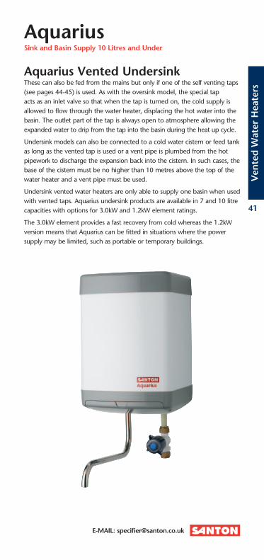
Aquarius Vented UndersinkThese can also be fed from the mains but only if one of the self venting taps (see pages 44-45) is used. As with the oversink model, the special tap acts as an inlet valve so that when the tap is turned on, the cold supply is allowed to flow through the water heater, displacing the hot water into the basin. The outlet part of the tap is always open to atmosphere allowing the expanded water to drip from the tap into the basin during the heat up cycle.
Undersink models can also be connected to a cold water cistern or feed tank as long as the vented tap is used or a vent pipe is plumbed from the hot pipework to discharge the expansion back into the cistern. In such cases, the base of the cistern must be no higher than 10 metres above the top of the water heater and a vent pipe must be used.
Undersink vented water heaters are only able to supply one basin when used with vented taps. Aquarius undersink products are available in 7 and 10 litre capacities with options for 3.0kW and 1.2kW element ratings.
The 3.0kW element provides a fast recovery from cold whereas the 1.2kW version means that Aquarius can be fitted in situations where the power supply may be limited, such as portable or temporary buildings.
AquariusSink and Basin Supply 10 Litres and Under

SPECIFICATION ADVICE: 01603 420128
Ven
ted
Wat
er H
eate
rs
42
AquariusTechnical Specification
Dimensions
A B C Weights (kg) Oversink (mm) (mm) (mm) Empty Full
A7/3 356 240 240 4.9 11.9 A7/1 356 240 240 4.9 11.9 A10/3 442 240 240 5.9 15.9
Undersink
AU7/3 356 240 240 4.9 11.9 AU7/1 356 240 240 4.9 11.9 AU10/3 442 240 240 5.9 15.9
Ordering Guide
Oversink Product Code Ltrs Rating
A7/3 94 010 001 7 3.0kW @ 240V (2.8kW @ 230V) single phase AC A7/1 94 010 002 7 1.2kW @ 240V (1.2kW @ 230V) single phase AC A10/3 94 010 003 10 3.0kW @ 240V (2.8kW @ 230V) single phase AC
Undersink
AU7/3 94 010 008 7 3.0kW @ 240V (2.8kW @ 230V) single phase AC AU7/1 94 010 009 7 1.2kW @ 240V (1.2kW @ 230V) single phase AC AU10/3 94 010 010 10 3.0kW @ 240V (2.8kW @ 230V) single phase AC
Oversink Undersink

E-MAIL: [email protected]
43
Ven
ted
Wat
er H
eate
rs
SpecificationElementCopper sheathed Element, incorporated into an easily removable heater plate, should replacement be necessary.Inner ContainerPressure tested to 1.38 bar (20psi). A minimum head pressure of three metres is required.Outer CasingThe main body is substantial gauge sheet steel, anti-corrosion treated and finished in white stoved enamel. End covers are moulded in grey ABS. The back has three fixing points for wall mounting.InsulationApprovedCFC/HCFCfree(ODPzero)polyurethane foam. GWP 2.72 (Global Warming Potential).Safety FeatureIPX4 rated.ThermostatCapillary type, adjustable 10°C – 70°C.Safety Cut-outModels are available with a thermal fuse cut-out fitted in series with the adjustable thermostat.Swivel Outlet – OversinkStainless steel tube 300mm, with 15mm push-fitconnection.Nootherpipeworkor spout or tap should be connected to the outlet.Inlet – OversinkAn inlet valve is supplied with 15mm compression connections.Connections – Undersink15mm Copper tails.ElectricalThe installation must comply with BS 7671 ‘Requirements for electrical installations’ (IEE Wiring Regulations). It must be fully earthed and permanently connected to the electrical supply through a double pole linked isolating switch with minimum breaking capacity suitable for the loading.ApprovalsBEAB and Kiwa approved. CE marked. ManufacturedintheUKinaBSENISO9001:2008, ISO 14001:2004 and BS OHSAS 18001:2007 registered factory.GuaranteeTwo years product guarantee, from date of purchase, with on-site service support. Full details are contained in the Installation Instructions supplied with each unit.
AquariusTechnical Specification

SPECIFICATION ADVICE: 01603 420128
Ven
ted
Wat
er H
eate
rs
44
The Santon range of taps has been chosen to complement the Aquarius range of water heaters. It consists of vented hot taps and matching cold taps for use with vented undersink water heaters, as well as standard taps which can be used with any other Santon storage unit. The taps are robust and made in traditional cast brass with a chrome finish.
AquariusVented Taps
130
8250
90
151
168
Compressionfittings15mm
O/D pipe
1/2" BSP(backnut& washersupplied)
Vented Pillar Hot Tap – TXH02This is a pillar (or high neck) tap version of model TXH01.
Vented Basin Hot Tap – TXH01
40
6916
8
8250
87
Compressionfittings15mm
O/D pipe
1/2" BSP(backnut& washersupplied)
This tap is constructed to control the flow of incoming mains water supply to an open outlet type electric water heater. This displaces the heated water in an unrestricted flow through the tap’s permanently open outlet. This vented hot tap is for full bore plumbing. Above the basin it is identical to the universal taps, so a matching cold tap is available if required.
A typical installation of an Aquarius Vented Undersink heater using a vented tap.

E-MAIL: [email protected]
45
Ven
ted
Wat
er H
eate
rs
AquariusVented Taps
87
90 11969
1/2" BSP (backnut& washer supplied)
Universal Basin Tap – TXU01
Thesetapsarepackedindividuallywithbotharedandbluebezelandarenormally used in cold tap form to match the TXH01.
Ref. TXU02: Order Code 94 970 018 This is a pillar (or high neck) tap version of model TXU01 to match TXH02.
50
1/2" BSP(backnut &
washer supplied)
Compressionfittings 15mm
O/D pipe
8250
168
180
180
140
73
Vented Mixer Tap – TXM01
This is similar in operation to the vented hot tap but has the additional advantages of mixing the heated and cold water at the outlet and is ideally suited to kitchen use.
Ordering Guide
Model Ref. Product Code
TXH01 94 970 014 TXH02 94 970 015 TXU01 94 970 017 TXM01 94 970 016

SPECIFICATION ADVICE: 01603 420128
Han
d H
ygie
ne
46
Electric handwash units offer many benefits when compared to traditional methods of supplying hot water in the washroom. They are more economical to run, as the water is heated instantaneously at the point of use, and therefore provide an energy efficient source of hot water for handwashing. Compact in size, they can be installed in a wide range of locations to provide hand wash facilities ensuring compliance with current Health and Safety legislation.
The Santon EV 2008 range is cost effective, with stylish design and excellent performance. Designed to supply heated water to one basin by means of a swivel spray outlet, the units are ideal for commercial use when control of the water flow is required. The range includes an instantaneous no-touch unit for hygienic means of providing hot water for hand washing.
EV 2008Efficient and Economical Handwashing

E-MAIL: [email protected]
47
Han
d H
ygie
ne
Performance
• Energyefficient–locatedatpointofuse,eliminatinglongpiperuns, and heats water on demand.
• Summer/Winterperformance–goodflowratesevenwithlowinlet water temperature.
• Flow/temperaturestabilised–forconsistentoutlettemperature.
Installation
• 15mmfemalepush-fitplumbingconnection–foreaseofinstallation.
• Concealedconnections–optionforwaterandelectricalsupplytobemade from rear of unit for neater, tidier installation.
Design
• 'Power-On'indicator.
• Slimlinedesign–compactfootprintrequiresonlysmallamountof wall space.
• Attractivestyling–fitsinwithtoday’sworkenvironment.
• Lowvelocitysprayplate–givesconsistentspraypatternoverwiderangeof flow rates for efficient handwashing without splashing.
• 200mmstainlesssteelswivelspout–fordurabilityandqualityappearance.
• Retrofittopreviousmodelforeaseofinstallation.
• No-touchcontroldialforon/off,temperature/flowsettingviaatamper-proofadjuster(NoTouchmodels).
Safety Controls
• Pre-setsafetycut-out–preventsoverheating.
• Pressurereliefdevice–preventshighpressurebuild-upshouldhandwashunitbecomeblockedorfrozen.
• Temperaturestabiliser–ensuresthatthetemperatureofthewaterismaintained across the range of water pressures.
EV 2008Features and Benefits

SPECIFICATION ADVICE: 01603 420128
Han
d H
ygie
ne
48
EV 2008Technical Specification
B C
A
D
B C
A
D
EV 2008 No Touch
EV 2008
Dimensions
Model A B C D (mm) (mm) (mm) (mm)
EV 2008 369 151 98 240 EV 2008 NT 369 151 87 240
Ordering Guide
Model Ref. Product Code Rating
EV 2008/3 94 020 015 3.1kW @ 240V (2.9kW @ 230V) single phase AC EV 2008 NT 94 020 017 3.1kW @ 240V (2.9kW @ 230V) single phase AC

E-MAIL: [email protected]
49
Han
d H
ygie
ne
SpecificationControlsCombined On/Off and temperature control knob with large finger/thumb grip foreaseofuse.Notouchcontrols–EasytouseNoTouchon-offdial.CasingThe unit is splashproof and is encased in a white moulded HIPS (High Impact Polystyrene) plastic cover which conceals both the plumbing and electrical connections. Inner Container Copper cylinder complete with Inlet and Outlet connections, pressure relief device and heating element.ElementCopper sheathed rod-type.Pressure ReliefA pressure relief device is incorporated in the base of the container to prevent high pressure build-up if the handwash unit shouldbecomeblockedorfrozen.High Temperature Cut-outA pre-set safety cut-out set at 52ºC prevents overheating should abnormal conditions arise – this will re-set at 42ºC. In addition there is a failsafe, second stage protection, which is not resettable and cuts out at 92ºC.Temperature StabiliserAn automatic temperature stabiliser ensures that the temperature of the water is maintained across the water pressure range.Pressure RangeMin: 1 bar. Max: 7 bar.Connections15mm female push-fit connection at base of unit for bottom or rear (concealed) connection.OutletStainless steel swivel spout with spray outlet (200mm).Spray PlateLow velocity spray giving consistent spray pattern, for efficient handwashing, over a range of flow rates.
InstallationFixing Base plate is secured to wall by two fixing screws, after which electrical and plumbing connections are made. Spout and front cover are then attached. Two screws secure the front cover.ElectricalSpecial requirements of the IEE wiring regulations should be observed when installing in bathrooms. Units must be permanently connected to the electrical supply through a double pole linked isolating switch. Can be supplied from a ring final circuit via fused spur with a double pole linked isolating switch with a 13A minimum breaking capacity. Cable: 1.5 – 2.5mm².ApprovalsBEAB and Kiwa approved.GuaranteeTwo years product guarantee, from date of purchase, with on-site service support. Full details are contained in the Installation Instructions supplied with each unit.
EV 2008Technical Specification

SPECIFICATION ADVICE: 01603 420128
Dri
nki
ng
Wat
er
50
Santon is one of the leading brands in the UK for water heating. For commercial applications, boiling water heaters have a number of advantages over traditional methods. For example, one of our smallest 2.5 litre units can supply over 150 cups of boiling water in one hour. The time saved in constantly boiling kettles to make drinks is vastly reduced, and the time spent waiting for a kettle to boil is removed completely. The Speediboil provides instant hot water.
SpeediboilBoiling Water ‘On Tap’
Features and Benefits
Performance
Speediboil provides a cost effective solution for a variety of commercial applications including canteens, offices, workshops, hairdressers and waiting rooms.
Installation
Ease of installation has long been a trademark of Santon products and this range is no exception. Full fitting instructions and easily accessible plumbing fittings provide a quick and easy solution.

E-MAIL: [email protected]
51
Dri
nki
ng
Wat
er
SpecificationRatings2.5kW @ 240V, all capacities.Outer CasingWhite ABS moulding.Thermal InsulationCFC/HCFCfree(ODPzero)pre-mouldedpolystyrene and thermoplastic blend.Water Container Moulded thermoplastic. Removable steam condensation chamber for maintenance access.Heat UnitLow watts density Superloy element for long life.Thermostat Electronic to control water temperature up to boiling point.Safety FeaturesAll models are low-pressure vented. Dry start protection by self re-setting bi-metal thermal cut-out. Boil dry protection by manually resettable disc-type bi-metal cut-out. IPX2 rated.
InstallationSpeediboil units have hook-on brackets for wall mounting, ideally over a draining board or drip-tray. 150mm clearance should be allowed around the unit for maintenance (refer to instructions).
PlumbingCold water feed should be taken directly from the mains – min pressure 0.5 bar (7psi), max pressure 10 bar (145psi). Bottom or rear entry using 15mm push-fit connections.ElectricalSupply (bottom or rear entry) can be taken from a suitable ring final circuit via a fused spur but must be via a double-pole linked isolating switch with a minimum break capacity of 13A. All electrical work must comply with the latest IEE wiring regulations.ApprovalsBEAB approved. CE marked. ManufacturedintheUKinaBSENISO9001:2008, ISO 14001:2004 and BS OHSAS 18001:2007 registered factory.GuaranteeTwo years product guarantee from date of purchase with on-site service support. Full details are contained in the Installation Instructions supplied with each unit.
SpeediboilBoiling Water ‘On Tap’
30
CG
F
ED
B
B
A
250mm approx
Worktop
30
CG
F
ED
B
B
A
250mm approx
Worktop
Dimensions
Capacity A B C D E F G Weight full (mm) (mm) (mm) (mm) (mm) (mm) (mm) (kg)
2.5 litres 445 290 190 80 115 101 152 8.4 5.0 litres 510 335 200 103 133 101 163 11.8 7.5 litres 510 335 262 103 133 101 225 15.4
Ordering Guide
Model Ref. Product Code Capacity
Speediboil 94 200 001 2.5 litres Speediboil 94 200 002 5.0 litres Speediboil 94 200 003 7.5 litres

SPECIFICATION ADVICE: 01603 420128
Inst
anta
neo
us W
ater
Hea
tin
g
52
PowerPack is a compact instantaneous water heater. It can supply more than one outlet or spray tap, provided only one outlet tap is used at one time. PowerPack is ideally suited to supplying heated water to a remote area, such as a garage or cloakroom. It can be concealed from view and thus be protected from vandalism.
PowerPackInstantaneous Water Heater
• Availablein7kWand9kWmodels.
• Idealforsupplyinghotwaterforbedsits, student accommodation and to remote areas.
• WhitemouldedvandalresistantABS casing.
• Hightemperaturecut-out for safety.

E-MAIL: [email protected]
53
Inst
anta
neo
us W
ater
Hea
tin
g
SpecificationControlsA pressure differential switch activates the unit when the water flows.CasingMoulded from white ABS.Inner ContainerGlass reinforced plastic cylinder, complete with inlet/outlet connections and element. A drain plug is fitted to drain thecontainertopreventfreezingifleftin winter.FittingsA pressure relief valve set to relieve at 10 bar is provided together with a tee-piece which must be fitted on the cold water inlet. This valve MUST be connected to waste (drain) via a tundish and the drain pipe should fall continuously and be of 22mm bore discharging in a safe visible manner. The pipe must not be reduced in bore or blocked under any circumstances and it should be protected from frost.
Safety FeatureIPX1 rated.Pressure RangeMin: 1 bar. Max: 7 bar.Connections½" BSP inlet and outlet.ApprovalsBEAB and Kiwa approved. CE marked. GuaranteeTwo years. Full details are contained within the Installation Instructions supplied with each unit.
PowerPackTechnical Specification
A
C D
B
Dimensions
Model A B C D (mm) (mm) (mm) (mm)
PowerPack 31 210 160 104
Ordering Guide
Model Ref. Product Code Rating
PowerPack 94 050 211 7.0kW @ 240V single phase AC PowerPack 94 050 212 9.0kW @ 240V single phase AC

SPECIFICATION ADVICE: 01603 420128
Com
bin
atio
n S
tora
ge
54
R Units are designed to supply hot water for handwashing, dishwashing and general cleaning purposes to cloakrooms, canteens and kitchen areas. Supplied with an integral cold water cistern, they are ideal for installations where the cold feed is from the mains supply but an unvented installation is impractical.
R UnitsWall Mounted Combination Storage
Suitable for direct connection to the mains water supply. These units are ideal for supplying hot water for multi-outlet applications.
The diagram below refers to a typical installation of an R Unit. The pressure at the outlet is determined by the height of the water heater – the higher the unit is mounted above the highest outlet, the greater the pressure. In no circumstances should the base of the water heater be lower than any outlet it is supplying.
Overflow
Basin
Cold water supply
Basin Basin Basin
Heater
A typical installation of a Santon R Unit
R Unit Selection Guide
Model Number of Basins
R25 2 R45 3 R70 4 – 5 R115 5 – 7
Note:Thesefiguresareforguidanceonlyand local conditions should be taken into accountwhensizingtheinstallation.
For full details contact our Specification Advice Hotline on 01603 420128 or fax 01603 420229.

E-MAIL: [email protected]
55
Com
bin
atio
n S
tora
ge
R UnitsTechnical Specification
E
B
D
C
A
SpecificationElementA 3.0kW alloy sheathed immersion heater is supplied fitted into the integral 2¼" BSP boss.ThermostatAdjustable from 40°C to 80°C with integral, manually re-settable, over temperature cut-out.Inner ContainerCopper rectangular tank. Pressure tested to 0.14 bar. The cold water feed tank is built into the top of the outer case and in the following capacities. R25: 4.5 litres, all other models: 8 litres. Supplied complete with ball valve and overflow which can be fitted left or right hand.CasingSubstantial gauge sheet steel anti-corrosion treated and finished in stoved enamel. White body and base.Insulation ApprovedCFC/HCFCfree(ODPzero)polyurethane foam. GWP 3.1 (Global Warming Potential).
Safety FeatureIPX1 rated.Approvals BEAB approved. CE marked. ManufacturedintheUKinaBSENISO9001:2008, ISO 14001:2004 and BS OHSAS 18001:2007 registered factory.Connections½" BSP (male) ball valve / ¾" BSP (male) overflow and hot water outlet.GuaranteeTwo years. Full details are contained within the Installation Instructions supplied with each unit.
Dimensions
Model Capacity A B C D E Weight (kg) (Ltrs) (mm) (mm) (mm) (mm) (mm) Empty Full
R25 25 880 452 215 307 680 15 45 R45 45 846 610 290 410 647 21 74 R70 70 1055 610 290 410 856 25 103 R115 115 1011 610 445 410 817 30 153
Ordering Guide
Model Ref. Product Code
R25 R25 R45 R45 R70 R70 R115 R115

SPECIFICATION ADVICE: 01603 420128
Imm
ersi
on H
eate
rs
56
Santon is a leading manufacturer of industrial immersion heaters. It supplies elements for use in commercial and industrial environments covering the heating of water, oil and other solutions. Whatever the application, Santon is able to provide the answer.
Water
Santon manufactures a wide range of immersion heaters for heating water in commercial and industrial environments. Two element sheath materials are supplied to cater for all water conditions – Superloy and Titanium. All Industrial Immersion Heaters are covered by a full 12 month guarantee. These heaters are supplied with a factory-fitted stem type thermostat.
A variety of fixing methods cover all conceivable installations, with loadings from 2.0kW available on a 2¼" BSP head, to 54kW available on a flanged fixing. Applications can vary from car wash machines to industrial calorifiers and swimming pool heaters.
When selecting which immersion heater is required, it is advisable to use the longest element that will fit into the vessel being heated. This ensures that heat dissipation is maximised and keeps the watts density of the element to a minimum, which prolongs element life.
Oils
Great care needs to be taken when selecting an immersion heater for oil and full details on the oil type, viscosity, etc. should be obtained from the oil manufacturer. Advice should be sought as to the most suitable watts density output rating permissible with the oil.
For the majority of applications the electrical loading per unit surface area of the immersed heating element is important and a special range designed for use in oil is required. If the correct rating is not used rapid breakdown of the immersion heater can occur with serious consequences to the industrial process concerned.
Immersion HeatersIndustrial Electrical Water Heaters

E-MAIL: [email protected]
57
Imm
ersi
on H
eate
rs
Environments
All Santon heaters are characterised by their ability to withstand the most arduous working conditions and are therefore supplied with terminal enclosures to suit. In the case of the ‘M’ and ‘L’ ranges, the immersion heater cover is manufactured in accordance with IP65. All thermostat pockets are made from Superloy.
Custom Built
In a number of applications it is not always possible to fit a standard immersion heater.
Our technical department can give expert advice in the specification and design of a heater to suit individual requirements. The following information will help us to specify the optimum method of heating the solution:-
• Typeoffluidtobeheated.
• Viscosityoffluid(ifapplicable).
• Sizeoftank.
• Lowestinitialtemperature.
• Maximumworkingtemperature.
• Maximumpermissiblelengthofheater element.
• Typeofheaterfixingrequired.
Immersion HeatersIndustrial Electrical Water Heaters

SPECIFICATION ADVICE: 01603 420128
Imm
ersi
on H
eate
rs
58
Immersion HeatersIndustrial Electrical Water Heaters / Technical Specification
Water 2¼" BSPT Fixing Complete With Control Thermostat
Loading Model Ref. Model Ref. Phases Immersed Length kW Superloy Titanium (mm) (ins)
2 My211 - 1 only 280 11 3 My311 - 1 or 3 280 11 3 My330 - 1 or 3 760 30 4 My411 - 1 or 3 280 11 4 My416 - 1 or 3 405 16 6 My616 MT616 1 or 3 405 16 6 My630 - 1 or 3 760 30 6 My642 - 1 or 3 1065 42 7.5 My724 MT724 1 or 3 610 24 9 My916 - 3 only 405 16 9 My927 MT927 1 or 3 685 27 9 My936 - 1 or 3 915 36 12 My1224 - 1 or 3 610 24 12 My1236 - 1 or 3 915 36 18 My1836 - 3 only 915 36
Water 2½" BSPT Fixing Complete With Control Thermostat
Loading Model Ref. Model Ref. Phases Immersed Length kW Superloy Titanium (mm) (ins)
6 Ly615 - 1 or 3 380 15 9 Ly920 - 1 or 3 510 20 12 Ly1226 - 3 only 660 26 15 Ly1532 - 3 only 810 32 18 Ly1838 - 3 only 970 38
A second pocket is provided to fit a manual reset limit thermostat.
Water Bolt-On Fixing Complete With Control Thermostat
Loading Model Ref. Model Ref. Phases Immersed Length kW Superloy Titanium (mm) (ins)
12 Dy1216 DT1216 3 405 16 18 Dy1816 - 3 405 16 18 - DT1823 3 585 23 24 Dy2416 - 3 405 16 24 - DT2430 3 760 30 24 - DT2436 3 915 36 30 Dy3027 - 3 685 27 36 Dy3627 - 3 685 27 45 Dy4527 - 3 685 27 54 Dy5436 - 3 915 36
Theseheatersareforhorizontalapplicationonly.Asecondpocketisprovidedtofitamanualreset limit thermostat.
Special elements are available for most types of fluids.
Please consult our Specification Advice Hotline on 01603 420128 or fax 01603 420229.

E-MAIL: [email protected]
59
Imm
ersi
on H
eate
rs
Immersion HeatersIndustrial Electrical Water Heaters / Technical Specification
Water 2¼" BSPT Fixing Complete With Cut-Out
Loading Model Ref. Model Ref. Phases Immersed Length kW Superloy Titanium (mm) (ins)
4.5 MGy414 - 1 or 3 355 14 6 MGy616 - 1 or 3 405 16
Oils 2¼" BSPT Fixing Complete With Control Thermostat
Loading Model Ref. Phases Surface Rating Immersed Length kW Steel (W/cm²) (W/ins²) (mm) (ins)
3 MO342 1 or 3 1.4 9 1065 42 2 MO224 1 only 1.6 10 610 24 3 MO336 1 or 3 1.6 10 915 36 5 MO560 1 or 3 1.6 10 1525 60 6 MO672 1 or 3 1.6 10 1830 72 1 MO112 1 only 1.9 12 305 12 3 MO330 1 or 3 1.9 12 760 30 4 MO442 1 or 3 1.9 12 1065 42 5 MO548 1 or 3 1.9 12 1220 48 6 MO660 1 or 3 1.9 12 1525 60
Note:Heaterswithanimmersedlengthover1.2m(4feet),requireinternalsupportinthevessel to remove strain from the head fixing.
Oils 2½" BSPT Fixing Complete With Control Thermostat
Loading Model Ref. Phases Surface Rating Immersed Length kW Steel (W/cm²) (W/ins²) (mm) (ins)
2 LO224 1 only 1.6 10 610 24 3 LO336 1 or 3 1.6 10 915 36 6 LO672 1 or 3 1.6 10 1830 72 1 LO112 1 only 1.9 12 305 12 3 LO330 1 or 3 1.9 12 760 30 5 LO548 1 or 3 1.9 12 1220 48 6 LO660 1 or 3 1.9 12 1525 60
Note:Heaterswithanimmersedlengthover1.2m(4feet),requireinternalsupportinthevessel to remove strain from the head fixing.
Flanges
A range of flanges is available to complement Santon immersion heaters.
For MY, MT, MGY and MO type Industrial Immersions 2¼" Universal mechanical flange – ref. F100U 2¼" Blanking plug – ref. F105.
For DY and DT type Industrial Immersions Brass flange – ref. F8462.
Thermostats
Contact our Specification Advice Hotline on 01603 420128 or fax 01603 420229.

SPECIFICATION ADVICE: 01603 420128
Use
ful I
nfo
rmat
ion
60
Useful InformationMetric
Conversion Formulae
1 litre = 1000 cu. cm. (61 cu. in.) 1 kg. 0.22 gal. 1.76 pt.
1 cubic metre = 1000 litres 35.31 cu. ft. 1.31 cu. yd.
1 metre = 39.37 in. 3.28 ft 1.09 yd.
1 sq. metre = 1550.39 sq. in. 10.763 sq. ft. 1.195 sq. yds.
1 kilogram = 2.204lb
Average cold Winter 4/7°C mains water Summer 15/18°C temperature
Water 10%onfreezing expansion 4% on heating due to to 100°C temperature
Heating and Electrical Data
1 kilowatt hour (kWh) = 3,412 British thermal units (Btu) 1 watt (W) = 1 joule per second (1 J/s) 1 kilowatt hour (kWh) = 860 kilocalories
One kilocalorie is the amount of heat required to raise 1 litre of water through 1°C. 1kWh raises 15.5 litres of water through 56°C.
Water Heating Calculations
kW loading = (litres x temp. rise °C) ÷ (14.3 x time in mins.) Time in mins. = (litres x temp. rise °C) ÷ (14.3 x kW loading) Litres = (14.3 x kW loading x time in mins.) ÷ (temp. rise °C) Temp. rise °C = (14.3 x kW loading x time in mins.) ÷ (litres)
Mean Water Temperature in °C
(Litres hot x temp. hot °C) + (litres cold x temp. cold °C) Total (hot + cold) litres
Temperature Conversion
°C = (°F – 32) x 0.555
Capacities of Cylinders and Tanks (Litres)
Cylinder Tank Height x dia. (cm²) length x breadth x height (cm) 1273 1000
Oil Heating Calculations
kW loading = litres per hour x temp. rise (°C) 1464

E-MAIL: [email protected]
61
Use
ful I
nfo
rmat
ion
Useful InformationImperial
Conversion Formulae
1 gallon = 277cu. in. (4546 cu. cm.) 10 lb (4.533kg.) 4.54 litres.
1 cubic foot = 6.23 gal. 0.028 cu. m 1 inch = 25.4 mm 1 foot = 304.8 mm 1 yard = 914.4 mm 1 sq. yard = 0.836 sq.m 1 pound = 0.4536 kg
Average cold Winter 40/45°F mains water Summer 60/65ºF temperature
Water 10%onfreezing expansion 4% on heating due to to 212°F temperature
Heating and Electrical Data
1 kilowatt hour (kWh) = 3,412 British thermal units (Btu) One British Thermal unit is the amount of heat required to raise 1 lb of water through 1°F. 1kWh (3,412 Btus) raises 3.41 gallons of water through 100°F
Water Heating Calculations
kW loading = (gallons x temp. rise °F) ÷ (5.7 x time in mins.) Time in mins. = (gallons x temp. rise °F) ÷ (5.7 x kW loading) Gallons = (5.7 x kW loading x time in mins.) ÷ (temp. rise °F) Temp. rise °F = (5.7 x kW loading x time in mins.) ÷ (gallons)
Mean Water Temperature in °C
(Gallons hot x temp. hot °C) + (gallons cold x temp. cold °C) Total (hot + cold) gallons
Temperature Conversion
°F = (°C x 1.7) x 3.2
Capacities of Cylinders and Tanks (Litres)
Cylinder Tank Height x dia. (in²) length x breadth x height (in) 353 277
Oil Heating Calculations
kW loading = gallons per hour x temp. rise (°F) 580

SPECIFICATION ADVICE: 01603 420128
Use
ful I
nfo
rmat
ion
62
SPECIFICATION ADVICE: 01603 420128
Use
ful I
nfo
rmat
ion
62
Approximate time in minutes to heat water through 56°C temperature rise.
Useful InformationRecovery Chart
Litres Loading in kilowatts
1 1.2 1.5 2 3 4 6 7.5 9 12 15 18 24 27 30 36 45 54
5 20 16 13 10 7 5
7 28 23 18 14 9 7
10 39 33 26 20 13 10
15 59 49 39 30 20 15 10
23 90 75 60 45 30 23 15
30 118 98 78 59 39 30 20
34 133 111 89 67 45 34 23
50 196 163 131 98 66 49 33 26
55 108 72 54 36 29 24
68 89 67 45 36 30 23
80 105 79 53 42 35 26
86 112 84 56 45 37 28
91 119 89 59 48 40 30
100 131 98 65 52 44 33
114 149 112 74 60 50 37
115 150 113 75 60 50 38
120 157 118 78 63 52 39
136 178 133 89 71 59 44 36 30
144 188 141 94 75 63 47 38 31
166 217 163 108 87 72 54 43 36
182 238 178 119 95 79 59 48 40
210 274 206 137 110 81 69 55 46
227 296 222 148 119 99 74 59 49
364 238 190 158 119 95 79 59
455 297 238 198 148 119 99 74
550 359 287 239 179 144 120 90 80 72 60 48 40
700 366 305 228 183 152 114 102 91 76 61 51
900 392 294 235 196 147 131 117 98 78 65
1200 392 313 261 196 174 157 131 104 87
1800 392 294 261 235 196 157 131
2500 408 363 326 272 218 181
3000 392 326 261 218
Suggested Volumes
Hot water in litres stored at 71ºC per person/bath/shower
Domestic Commercial Wash basin 1.1 1.1 to 2.3 Spray taps - 0.6 to 1.4 Baths 55 70 Kitchens 3 2.3 to 7 Cleaners sinks - 9 per day Dishwashing machines 2 4 Washing machines 20 20 to 60 Showers 5 to 9 per min. 9 to 12 per min. Hairdressers: Ladies – per basin per hour - 36 Mens – per basin per hour - 7