aqua glider - engr.calvinblogs.org · 26 will provide a report on their progress as they to deliver...
TRANSCRIPT
.
AQUA GLIDER
-- A Scuba Mobility Solution --
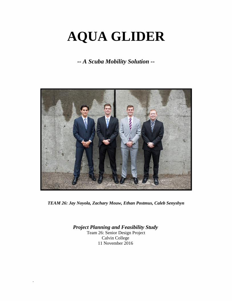
TEAM 26: Jay Noyola, Zachary Mouw, Ethan Postmus, Caleb Senyshyn
Project Planning and Feasibility Study Team 26: Senior Design Project
Calvin College
11 November 2016
.
© 2016
Calvin College and Jay Noyola, Zachary Mouw, Ethan Postmus and Caleb Senyshyn

i
EXECUTIVE SUMMARY
Through the course of ancient history, the seas and its depths were venerated for their immense power and
great mystery. However, the exploration of its depths were unable to be explored efficiently until the
development of the self-contained underwater breathing apparatus or SCUBA in the mid-twentieth century.
Since then there have been many innovative improvements to enhance the Scuba experience including the
relatively recent developments of the diver propulsion vehicle (DPV). DPV’s have been designed to conserve
diver’s air supplies while allowing for faster and more efficient movement underwater. Senior design Team 26 still believes that there is a gap in the market for a more innovative and technologically
advanced recreational DPV. The goal of this project is to develop a DPV that helps bridge this gap through a
scuba mobility solution called the Aqua Glider. While the Aqua Glider will maintain an electric motor driven
propeller system, it will be designed to achieve higher speeds with more navigational control than many of
the traditional designs. The Aqua Glider is specified to be able to achieve up to 5 mph and dive depths of 130
feet to accommodate recreational dives. Recreational divers generally will explore lively coral reefs, tropical
waters or other relatively shallow dive sites, therefore it was also necessary to equip the Aqua Glider with
steering and buoyancy control. With a new hydrodynamic shape that resembles that of a stingray, a fiberglass
body, and a dual propeller system, the team attempts to meet these innovative goals. The scope of this project
is to design and produce a prototype of the Aqua Glider that will serve as a proof of concept. The team will
accomplish this within the time frame and budget dictated by ENGR 339/340, the capstone course that this
project fulfills. The first half of the project is honed in on the planning and feasibility of the Aqua Glider concept. Through
project management strategies, conceptual research, performance calculations, and 3D developments, Team
26 will provide a report on their progress as they to deliver a product to equip divers to efficiently explore the
underwater world—a world full of life, history, meaning and God’s beauty.

ii
TABLE OF CONTENTS
1. Introduction ................................................................................................................................................... 1
1.1 The Motivation ........................................................................................................................................ 1 1.2 Context .................................................................................................................................................... 1 1.3 Problem Definition .................................................................................................................................. 1 1.4 Team Members ........................................................................................................................................ 2
1.4.1 Ethan Postmus .................................................................................................................................. 2 1.4.2 Zachary Mouw.................................................................................................................................. 2 1.4.3 Jay Noyola ........................................................................................................................................ 2 1.4.4 Caleb Senyshyn ................................................................................................................................ 2
2. Project Management ..................................................................................................................................... 3 2.1 Team Organization .................................................................................................................................. 3 2.2 Project Breakdown .................................................................................................................................. 3
2.2.1 Power ................................................................................................................................................ 3 2.2.2 Buoyancy .......................................................................................................................................... 3 2.2.3 Hydrodynamics................................................................................................................................. 3 2.2.4 Controls ............................................................................................................................................ 4
2.3 Schedule .................................................................................................................................................. 4 2.4 Budget ..................................................................................................................................................... 4 2.5 Method of Approach ............................................................................................................................... 5
3. Requirements & Specifications .................................................................................................................... 7 3.1 Operation ................................................................................................................................................. 7
3.1.1 Speed ................................................................................................................................................ 7 3.1.2 Size & Weight .................................................................................................................................. 7 3.1.3 Battery & Run Time ......................................................................................................................... 7 3.1.4 Bouyancy & Depth ........................................................................................................................... 7 3.1.5 Navigational Control ........................................................................................................................ 8 3.1.6 Waterproof & Structure .................................................................................................................... 8
3.2 Aesthetics ................................................................................................................................................ 8 3.3 Safety ...................................................................................................................................................... 8
3.3.1 Key Safety Considerations ............................................................................................................... 8 3.3.2 Additional Safety Considerations ..................................................................................................... 9
4. Design Alternatives and Selection .............................................................................................................. 10 4.1 Power .................................................................................................................................................... 10
4.1.1 Design Research (Battery) .............................................................................................................. 10 4.1.2 Design Considerations & Alt. ........................................................................................................ 10 4.1.3 Design Decisions ............................................................................................................................ 10 4.1.4 Design Research (Motors & Propellers) ......................................................................................... 12 4.1.5 Design Considerations & Alt. ........................................................................................................ 12 4.1.6 Design Decisions ............................................................................................................................ 12
4.2 Bouyancy............................................................................................................................................... 13 4.2.1 Design Research ............................................................................................................................. 13 4.2.2 Design Considerations & Alt. ........................................................................................................ 14 4.2.3 Design Decisions ............................................................................................................................ 14
4.3 Hydrodynamics ..................................................................................................................................... 15 4.3.1 Design Research ............................................................................................................................. 15

iii
4.3.2 Design Considerations & Alt. ........................................................................................................ 16 4.3.3 Design Decisions ............................................................................................................................ 16
4.4 Material & Waterproof .......................................................................................................................... 16 4.4.1 Design Research ............................................................................................................................. 16 4.4.2 Design Considerations & Alt. ........................................................................................................ 17 4.4.3 Design Decisions ............................................................................................................................ 17
4.5 Controls ................................................................................................................................................. 17 4.5.1 Design Research ............................................................................................................................. 17 4.5.2 Design Considerations & Alt. ......................................................................................................... 18 4.5.3 Design Decisions ............................................................................................................................ 18
5. Product Design Implementation ................................................................................................................. 19 5.1 System Architecture .............................................................................................................................. 19 5.2 CAD & 3D Modeling ............................................................................................................................ 19 5.3 Thrust & Trolling Motor Solution ......................................................................................................... 22
5.3.1 Battery Solution .............................................................................................................................. 22 5.4 Bouyancy Solution ................................................................................................................................ 23 5.5 Material Solution ................................................................................................................................... 24
6. Business Plan .............................................................................................................................................. 25 6.1 Market Research .................................................................................................................................... 25 6.2 Competitive Strategy ............................................................................................................................. 25 6.3 SWOT Analysis .................................................................................................................................... 25
6.3.1 Strengths ......................................................................................................................................... 25 6.3.2 Weaknesses..................................................................................................................................... 25 6.3.3 Opportunities .................................................................................................................................. 26 6.3.4 Threats ............................................................................................................................................ 26
6.3 Cost Estimate ........................................................................................................................................ 26 6.3.1 Development................................................................................................................................... 26 6.3.2 Production ...................................................................................................................................... 26 6.3.3 Distribution ..................................................................................................................................... 26
7. Conclusion .................................................................................................................................................. 27 7.1 Potential Risks and Issues ................................................................................................................. 27 7.2 Project Status ..................................................................................................................................... 27 7.3 Project Feasibility .............................................................................................................................. 27 7.4 Summary ........................................................................................................................................... 28
8. Acknowledgements ..................................................................................................................................... 29 9. Citations ...................................................................................................................................................... 30 10. Appendix ................................................................................................................................................... 31

iv
TABLE OF FIGURES
Figure 1. Power Sonic PS-12180 Battery ...................................................................................................... 12
Figure 2. Minn Kota Endura C2 40 Trolling Motor ...................................................................................... 13
Figure 3. Parker Pressurized Cylinder ........................................................................................................... 15
Figure 4. Various Shapes and their Coefficient of Drag ................................................................................ 15
Figure 5. Side View of Aqua Glider .............................................................................................................. 16
Figure 6. Submarine Dynamics ...................................................................................................................... 18
Figure 7. System Architecture for the Aqua Glider ....................................................................................... 19
Figure 8. CAD Model of the Aqua Glider ..................................................................................................... 20
Figure 9. CFD Results.................................................................................................................................... 20
Figure 10. Flow Trajectory CFD Analysis..................................................................................................... 21
Figure 11. CFD Pressure Cut Plot .................................................................................................................. 21
TABLE OF TABLES
Table 1. Aqua Glider Budget ........................................................................................................................... 5
Table 2. Project Method of Approach .............................................................................................................. 6
Table 3. Comparison of Battery Types and Models ....................................................................................... 11
Table 4. Trolling Motor Decision Matrix....................................................................................................... 13
Table 5. Component Weight and Volume Contribution ................................................................................ 23
TABLE OF EQUATIONS
Equation 1. Drag Force Calculation…………………………………………………………...…………… 22
Equation 2. Battery Calculation……………………………………………….…………………………… 22
Equation 3. Buoyant Force Calculation………………………………….…...……………………………. 23

1
1. INTRODUCTION
1.1 THE MOTIVATION
Team 26 believes that the Aqua Glider project fits into a greater context than merely creating an efficient and
excellent Scuba mobility solution. As Christian engineers, the highest priority and primary motivation in
designing the Aqua Glider needs to be to glorify God and equip others to do the same. The Aqua Glider is a
prime example of a way to equip others to glorify God, as it is a vehicle that effectively and efficiently
provides a means for divers to celebrate His underwater creation. Psalm 148 is the theme Bible passage of
this project as it discusses how everything above and below the sea directs praise to God. In this way, the
team desires the Aqua Glider to be a resource in demonstrating this attitude towards God. In this same vein, Team 26 also chose to design and develop an underwater diver propulsion vehicle (DPV)
because of its member’s desire for active lifestyles and enthusiasm for learning new activities. There is also
a detailed level of complexity that accompanies the design of a device that is submerged and operates in
underwater environments and the team looks forward to solving the challenges that it presents. In this portion
and stage of design, the team will be developing a scuba mobility design solution and assessing its feasibility.
1.2 CONTEXT
There are many different types of Scuba diving, including technical deep sea, commercial, military, and
recreational diving. The most common type of Scuba diving is recreational and this is the type of diving that
the Aqua Glider is catered towards. Recreational divers will generally explore coral reefs, tropical waters,
shipwrecks, or other shallower depth dive sites. Recreational dive depths are limited to 130 feet, therefore a
DPV must be capable of maneuvering through a large range of environments encountered at these depths.
1.3 PROBLEM DEFINITION
The primary constraint that a Scuba diver is subject to is the duration of the dive. Dive time is directly limited
to the air supply that a diver can carry with them. The more a diver exerts themselves, the less efficient they
are with that air supply. Additionally, as a diver traverses to deeper depths, the lungs are compressed and
require more air supply to equalize the lung pressure, cutting the dive shorter. Furthermore, movements under
water are slow, restricting the area of the dive site that a diver is able to explore. Consequently, a DPV will
not only allow for a longer dive time but also equip the diver with the capabilities to explore a larger area.
There have been many DPV designs that have made their way into the market, but Team 26 thinks the market
is narrow and focuses merely on variations of one design. A standard DPV consists of a torpedo shape with
one propeller placed directly in front of the diver, at the rear of the device. Additionally, few DPV’s of this
type have the capability of conducting turns independent of the diver’s body movements. Team 26 believes
that they can develop an innovative DPV that extends beyond some of the traditional designs to deliver a new
hydrodynamic body with higher speeds and navigational control.
2
1.4 TEAM MEMBERS
1.4.1 ETHAN POSTMUS
Ethan Postmus is a senior Mechanical Engineering student at Calvin College. In the summer of 2015, he
interned at Monroe Products in Grand Rapids, MI. The internship developed his experience with data analysis
and process improvement for production cells. During the summer of 2016, Ethan interned at Innotec
Corporation in Zeeland, MI. There, he was able to gain valuable hands-on experience in multiple facets of
engineering, such as project management, troubleshooting, and data analysis. He will use his skills in
mechanical operations along with fluid dynamics to propose solutions to obstacles that emerge. In his spare
time, Ethan enjoys spending time with friends, playing games, and various outdoor activities. Developing the
Aqua Glider gives him a chance to combine multiple facets of his interests into something new and exciting
while participating in solving problems.
1.4.2 ZACHARY MOUW
Zachary Mouw is a senior mechanical engineering student with an international designation. During the
summer of 2016, he interned with GMB Architecture and Engineering in Holland, MI. At GMB, he received
experience in engineering consulting, specifically with respect to HVAC design. He will use his thermal and
fluid dynamics experience to address issues that will arise with buoyancy and fluid flow of the Aqua Glider.
He also will further his project management skills to adjust the project time table as new issues arise through
the duration of the design. Outside of his academic studies, Zachary enjoys engaging in athletic and outdoor
activities. He will be able to use his active understanding to help address issues that will arise in how the user
interfaces with the vehicle. The Aqua Glider is a unique project where he can integrate these passions and
skills to address the problems that will arise throughout the development of the Aqua Glider.
1.4.3 JAY NOYOLA
Jay Noyola is a senior mechanical engineering student with a determination to use his Calvin College
experience to help and lead. During the summer of 2015, he interned at Granger Co. in the Engineering
department and worked on data analysis and project management. He got experience with CAT Natural Gas
engines and sorted through data to optimize the running of the engines. Jay will use his experience with data
analysis and problem solving to optimize The Aqua Glider and get it functioning at its highest capacity. Jay
also is a captain on the Calvin men’s soccer team, and has gained much knowledge in leadership. He will use
his ability to lead and motivate to get the best from the team and keep to moral high in crucial situations.
1.4.4 CALEB SENYSHYN
Caleb Senyshyn is a senior mechanical engineering major at Calvin College. During the summer, he interned
at Bailey Edward architecture and engineering. During his internship, he worked on mechanical and electrical
system sizing and design. In this position, he worked to find the most cost effective heating and cooling
solution to fulfill the customer’s needs while minimizing costs. This experience will help him weigh the pros
and cons of certain design decisions in the Aqua Glider project to find the best use of the team’s resources.
Caleb was also faced with juggling multiple different projects with shifting timetables during his internship.
This experience with being flexible with timetables and identifying the most critical projects will help the
team distribute manpower effectively and sort project priorities when the schedule begins to shift.

3
2. PROJECT MANAGEMENT
2.1 TEAM ORGANIZATION
Each member on the team assumed a role in the management of the project. Team advisor Professor Renard
Tubergen, served as the design mentor for the group. Professor Tubergen was a resource for any questions
the team had about the design project and was ultimately the management level that the team reported to. The
team also has a marketing consultant, Mike Palmer who owns the American Dive Zone in Grand Rapids.
Mike will serve the team by providing crucial knowledge into the diving market and what products the diving
community are interested in. Team members Ethan and Zachary served as the internal project coordinators
and were given the task of allocating work while ensuring the project stayed on course. Team member Jay
Noyola served as the project communications director and was in given the responsibility of setting up
meetings with external resources. Caleb assumed the role of website developer and budget manager, as he
maintained an informational and aesthetically pleasing website while ensuring that the team stayed within the
project’s budget.
2.2 PROJECT BREAKDOWN
The team divided the Aqua Glider project into four main design categories: power, buoyancy, hydrodynamics,
and controls. This presented the opportunity for each team member to lead the research in one of the design
topic fields. However, this did not mean that a single team member completed all the requirements for that
category alone. The development and calculations were a shared task in each of the design areas, with the
task leader ensuring all the elements for a given topic were accounted for.
2.2.1 POWER
Determining the power necessary for the vehicle required research into the implementation of how battery
packs can be used to power electric motors that ultimately drive the propellers to produce the specified thrust.
This job also considered the mechanics involved with gear and shaft systems for variable speeds while
maintaining a waterproof design. Caleb Senyshyn led the power and motor application of the project
2.2.2 BUOYANCY
The primary goal of the buoyancy portion of the design is to attain a level of neutral buoyancy for the vehicle.
This area of research will evaluate the most effective way to eliminate the need for a diver to constantly have
to control the buoyant state of the DPV. This will provide the diver with a simple operation and more efficient
ride. Buoyancy determination is different for fresh and saltwater environments which also adds a level of
complexity to the design of the Aqua Glider. Zach Mouw heads the buoyancy control.
2.2.3 HYDRODYNAMICS
The main focus of the hydrodynamic aspect of the project is to develop a dynamic body shape that eliminates
the drag and frictional losses the DPV will experience, while also having an attractive look to appeal to the
customer. The challenge is to accomplish a hydrodynamic shape within the specified dimensions. Material
selection also plays a crucial role in hydrodynamics as the efficiency of the device is determined by the ability

4
of the vehicle to achieve smooth fluid flow across as much of the surface as possible. Ethan Postmus leads
the research and application of hydrodynamic principles and material analysis for the craft. ‘
2.2.4 CONTROLS
In the realm of controls, the team aimed to implement a level of maneuverability control in the Aqua Glider,
a feature not seen in many of the current DPV’s. Controls are necessary to make direction and depth changes
more effective. This area of research also included research into the implementation of the controls hardware
necessary for the device. Jay Noyola heads the controls and steering portion of the project.
2.3 SCHEDULE
The planning for the semester planning began with a Gantt chart that can be seen in Appendix A. The Gantt
chart displays the initial scheduling expectation determined by the team. However, as the semester went on
the team had to alter the schedule weekly to accommodate new ideas and tasks. The team was dedicated to
holding meetings on Tuesday and Thursday nights in order to continually give updates on the project’s
progress and alter the schedule as necessary. While most of first semester involves scoping and planning the project, second semester consists of
implementation and construction of plans. The Gantt Chart for the construction of the prototype can also be
found in Appendix A. Within the scope of this project and the time allotted, the two largest risks that are
presented and will continue to arise are that of buoyancy and sealing. Therefore, the team will allocate most
of its resources and time during the first half of the prototype development to prove the sealing and buoyancy
concepts.
Before construction, the team will close the learning curve gap for the different processes needed to build the
device. This includes waterproofing the fiberglass construction, control wiring, and propeller mounting. To
close the gap, small scale models will be constructed. The team will submerge the models in water using
various sealing methods to identify the best sealing methods for the full scale model.
Additional tests will be conducted for the controls, motors, and electrical system, initially set up without the
frame. This will allow the team to test the motors and ballast tanks to ensure the controls dictate the proper
behavior of the power and buoyancy systems. After all small scale testing is complete, a full scale frame will
be made and the electrical system will be implemented and sealed. Through leaving adequate time to test the
model, the risks of waterproofing and buoyancy will be greatly reduced.
2.4 BUDGET
The Aqua Glider is allotted a $500 budget for the design and construction of the device. The team plans to
dedicate most of the budget to the development of a prototype that will serve as a proof of concept in the
second half of the course. A projection of the budget can be seen in Table 1.

5
Table 1. Aqua Glider Budget
Purchase Item Cost ($) Budget % Motor (2) 240 48
Ballast Tanks (2) 72 14 Ballast Motor 26 5
Battery (2) 80 16 Material (20.7 sq. ft) 0 0
Electrical Connections 0 0 Buoyancy Control Switch 4 1
Seals 10 2 Charger 0 0
TOTAL COSTS $430 86%
The cost of motors is a large chunk of the budget, but the decision was made to use lower powered motors
for a lower cost in order to assure the prototype will stay under budget and serve as a proof of concept. Lead
acid batteries were the chosen type of batteries because of their low cost and commonality for the size needed.
Longevity and ability to recharge are lost compared to lithium batteries, but the cost for a specific lithium
battery was out of the price range. The lead batteries will serve well for the prototype and will keep the project
under budget. Longer lasting and lighter batteries can easily be installed for a future design. The decision is
more detailed in the Power section 4.1. The last accommodation was choosing fiberglass material as opposed
to spending extra money on carbon fiber for the shell of the Aqua Glider prototype. Some of the fiberglass
will be provided by Calvin, or purchased through Calvin for a discounted rate. The difference in strength of
the two materials is minimal, and the extra cost for carbon fiber was not feasible. The decision is more detailed
in the Material section 4.3. About 70 dollars still remains in the budget for testing materials and seals.
2.5 METHOD OF APPROACH
Initial project requirements for the DPV were determined on the basis of a market analysis on the traditional
torpedo shaped designs (section 6). While the team desired to stretch the boundaries of the traditional DPV
design, the existing market provided a baseline for the performance of the Aqua Glider. In addition to the
market analysis, the team developed a two-page story about how the Aqua Glider was to be used to provide
vision and serve as another baseline for the specifications and requirements. Following the determination of
the requirements of the project, research was conducted as a means of accessing and creating a foundation
for developing design alternatives. Team 26 then assessed the design alternatives to reach final design
decisions. Calculations, modeling, and analysis could then be conducted to assess the feasibility of the project.
The simplified method of approach can be separated into five phases that are summarized in Table 2.

6
Table 2. Project Method of Approach
Phase No. Task
Phase I Problem Definition
Problem Selection Visionary Story
Market Research Phase II
Specification Development Specification Development
Project Brief
Phase III Research and Selection
Power Research Buoyancy Research
Hydrodynamics Research
Controls Research
Alternatives Development
Design Selection
Phase IV Design Analysis
Solidworks Modeling CAD Simulation
Calculations
Component Selection Phase V
Feasibility Study Business Plan PPFS Analysis
The project began in Phase 1 where the team gathered a variety of different project ideas. Eventually the Aqua
Glider was decided upon based on resources available, feasibility, and an overall interest for the project. After
a project was chosen, a specific story was written to get a feel for the specifications of the device, followed
by a lot of product research. Phase 2 was completed by narrowing down the specification development and
creating a project brief. Phase 3 involved splitting up the project into different research topics as seen in Table
2 and gaining as much knowledge and information as possible to apply to the project. After a significant
amount of research was done and alternative designs were formed, a design selection was made. Phase 4
involved calculations, modeling, and simulations to analyze the design. After analysis of the design, real
components were selected. The components and design led to Phase 5, where a business plan and PPFS
Analysis were created to form a proper feasibility study.

7
3. REQUIREMENTS & SPECIFICATIONS
3.1 OPERATION
3.1.1 SPEED
The vehicle must be able to achieve an adequate speed that will provide the diver with the ability to attain
larger range distances in a single dive. A maximum speed specification of 5 mph was determined to give
divers a large range on a dive at an enjoyable speed. This is at the high end of many of the existing DPV’s on
the market and will give the Aqua Glider an edge in the market. A diver will also desire to have control over
their range of movement depending on the environment explored. Therefore, variable speed control is also
an important aspect that will be incorporated into the design.
3.1.2 SIZE & WEIGHT
The Aqua Glider will also need to be required to be easily transported above water and simple to manage
underwater. Therefore, the DPV must be designed into a light and compact shape while maintaining its
hydrodynamic effectiveness. It was decided that the DPV should weigh no more than 125 pounds as to
maintain the possibility of unassisted manual transportation of the device. The 125-pound specification is a
ceiling limit and the team will make the Aqua Glider as light as possible. The vehicle is also required to fit
within a compact constraint, not only for flexibility in maneuverability underwater, but also to have the
capability of being transported in the trunk of a midsized vehicle.
3.1.3 BATTERY & RUN TIME
The battery life should exceed or match that of a standard dive time. Recreational dives last around one hour,
therefore the DPV should operate without needing a recharge for a minimum of one hour. The one hour run
time is specified at the maximum speed operation. Considering that the DPV will likely not be operating at
the maximum speed through the duration of the dive, the one hour run time is an adequate specification. The
turnover time for the DPV is determined by the time capabilities of the battery to recharge. Therefore, the
DPV will be able to recharge in eight hours or under. This allows for the device to be charged overnight and
ready for a dive the following day. Recreational dives are often over vacations and people will dive over a
weekend or two-day period. Therefore, the DPV will need to be able to be easily rechargeable at any place
with a normal 12-volt outlet. The charging adapter must also be independent of the vehicle.
3.1.4 BOUYANCY & DEPTH
The device must have neutrally buoyant capabilities for optimal operation. A non-neutrally buoyant device
could result in the diver using additional energy to maintain buoyancy, the very thing the DPV is attempting
to avoid. The device must also be operable and buoyant in both salt and fresh water, therefore the physical
characteristics of each environment must be taken into consideration. Ballast tanks will be placed on the DPV
to ensure neutral buoyancy can be reached in any environment at any depth up to 130 feet. The device will
be equipped with buoyancy capabilities of traversing depths of up to 130 feet as this is maximum depth rating
for a recreational dive.
8
3.1.5 NAVIGATIONAL CONTROL
One of the key requirements for the Aqua Glider is to equip the DPV with navigational turning controls. The
implementation of these controls will reduce the amount of body movements required to operate the vehicle
and consequently increase the efficiency of diver’s oxygen supply. The device will be capable of turning a
full 180 degrees in under 10 seconds.
3.1.6 WATERPROOF & STRUCTURE
For the device to operate properly, it must be entirely waterproof. No water may enter into the DPV during
use as that would prove detrimental to the operation of the device and safety of the diver. The structural design
will be robust to withstand both the pressures that occur deep underwater and minor collisions.
3.2 AESTHETICS
Team 26 understands that delightful harmony is a key design consideration that needs to be integrated into
the Aqua Glider. Often times, the purpose of a dive is to explore the natural beauty of the aquatic environment
and therefore the Aqua Glider’s aesthetic integration into the environment is an important aspect. The Aqua
Glider should not detract or serve as a barrier to the diver’s experience of creation. Therefore, the Aqua Glider
should aesthetically blend into the natural aquatic environment. The design is required to be derived from
organic reflections of its natural environment. The Aqua Glider should be appealing to the diver, and have
more innovative features than the traditional torpedo design. The Aqua Glider is a sleek and unique design,
but is not unnatural. The shape is a lot like a manta ray and the aerodynamic shape gives it a smooth riding
experience. The shape is meant to blend in with the environment and not cause a commotion in the water. To
ensure a low profile underwater the Aqua Glider is also made to be very quiet. The noise is held to below 100
decibels as to not startle and creatures when the device is running. This is about the sound of open ocean
ambient noise according to the National Oceanic and Atmospheric Administration [1].
3.3 SAFETY
3.3.1 KEY SAFETY CONSIDERATIONS
Safety is a major component in the design decisions the team made. Scuba diving is an inherently dangerous
activity with a significant need for safety precautions. Because of this, it was very important for the team to
design the Aqua Glider in a way that did not increase the chance of an accident occurring during a dive. In
order to maximize the safety of the vehicle, the team developed an FMEA found in Appendix E that outlines
a few of the major safety considerations.
The highest risk was in waterproofing. If the vehicle were to flood, a number of aspects could put the diver
at risk. The vehicle would lose ideal buoyancy conditions and begin to sink. As the device is connected to the
diver, this could potentially pull the diver down at an uncontrollable rate. In order to mitigate these risks, the
team spent a significant amount of time researching the best possible waterproofing practices. This involved
researching how to waterproof all the areas in the shell where controls would need to come through as well
as which materials would provide the best waterproofing properties for the shell.

9
A second area where safety considerations were taken into account was with the propellers. The two
propellers used to drive the device through the water are spinning extremely fast and are in close proximity
to the diver. Because of this, it is important that the team designed a duct around the propellers to keep them
from contacting with the diver. In addition to the ducted fans, the team needed to ensure that any straps or
hoses hanging from the diver do not get sucked into the front of the device.
Finally, in case the diver faced an emergency situation, a couple of quick release options will be available.
The first quick release would consist of the buoyancy weights attached to the DPV. If the diver faced an
emergency situation where the Aqua Glider suddenly began to sink, they will be able to quickly release the
weight. Similarly, if the diver thinks that their life is in too much danger connected to the DPV, they can
quickly release the harness clip and ditch the Aqua Glider completely.
3.3.2 ADDITIONAL SAFETY CONSIDERATIONS
A safety clipping mechanism will be incorporated to keep the diver with the DPV during operation. A clip
will allow the diver to be pulled by the device rather than using arm strength to hold on. Additionally, if the
diver needed to use a hand to check gauges or make adjustments, the clip would provide that capability. Ducting the propellers provides a significant safety improvement on top of its hydrodynamic benefits. A diver
has a large amount of cables, tubes, and straps on them, and the ducting on the propellers will keep them from
getting caught. This safety aspect will protect the diver from a potentially serious situation and the DPV from
getting damaged in operation. In the event that the device runs out of battery during operation, an automatic float mechanism will be
incorporated. Integrating this safety facet will ensure that the diver does not lose the DPV just because the
battery was drained.
In an attempt to avoid injury while transporting the device to and from water, handles will be installed in
strategic locations. Ideally, one person will be able to move it, however, in the case that it is a two-person job,
the handles will provide the necessary control.

10
4. DESIGN ALTERNATIVES AND SELECTION
4.1 POWER
4.1.1 DESIGN RESEARCH (BATTERY)
The first aspect of the batteries the team researched was their chemical composition. The first type of battery
that was considered was lead-acid batteries. These batteries are extremely common, and therefore, cost
effective. Lead-acid batteries come in a variety of sizes so finding a battery to meet the Aqua Glider’s
application was not difficult. The downsides of these types of batteries is their weight and energy density.
Lead-acid batteries are notoriously heavy and large. In addition to this, these types of batteries are not as
resilient to repeated full drain and recharge. Nickel Metal Hydride (NiMH) were another promising battery option for the team. NiMH batteries are
generally very long lasting batteries that will not lose significant performance after recharging multiple times
However, they will tend to lose performance if they are required to sit for long periods of time without use.
NiMH batteries are also much more expensive than lead-acid batteries and are far less common. They are
also most commonly used in very small scale applications, like model airplanes and RC cars. Due to this,
finding a NiMH battery large enough to fit the team’s application will be difficult.
The last type of battery that was considered was Lithium batteries. Lithium batteries offer the best life and
react relatively well to being left for long periods of time. Lithium batteries are also very light, and therefore
have a high energy density. The downside to lithium batteries is their cost and availability. They also tend to
be used in small applications like NiMH batteries, so finding a large enough battery could be difficult. Lithium
batteries also tend to be used in specialty cases and therefore can be cost prohibitive to the team’s generalized
application. [2] [3] [4]
4.1.2 DESIGN CONSIDERATIONS & ALT.
After researching a few examples of each type of battery, it was clear that the Lithium and NiMH batteries
were not feasible for the project. As can be seen in Table 3, the Dakota Lithium ion battery offers only 10
Amp hours (Ah) of capacity with a $25 price tag. Similarly, the Tenergy battery offered 2 Ah for $25. This
is due to the fact that NiMH batteries provide power in very small packages but do not meet the energy
capacity necessary for the Aqua Glider. In all, these battery types simply were not feasible for this application.
Their price points were much too high and did not provide the necessary power for the device to meet the
design specifications.
4.1.3 DESIGN DECISIONS
This led the team to ultimately decide that lead acid batteries would provide the necessary energy density,
discharge rate for the motors while fitting nicely into the budget. There is a large market for lead acid batteries
but certain specifications had to be met by the batteries so they could work with the team’s chosen motor
type.
Firstly, the battery the team chose would need to be a sealed lead acid (SLA) battery. This ensures that none
of the internal chemicals of the battery would spill out into the interior of the Aqua Glider. In addition to not
11
spilling, the SLA type batteries allow the team to orient the battery in whatever way works best. All the lead
acid batteries the team looked at were of the SLA type because this is a necessary characteristic for the battery.
All of the lead acid batteries under consideration by the team also meet the necessary maximum discharge
rate of 42 Amps as dictated by the motor manufacturer.
The next aspect of the batteries that the team looked at was a characteristic known as deep cycle batteries.
Deep cycle batteries (represented in Table 3 by the designation PDC) offer a higher resilience to being fully
discharged. With normal lead acid batteries, repeatedly fully discharging the batteries has the potential to
shorten the total life of the battery. The team looked at a selection of these types of batteries, but ultimately
made the decision that the batteries used in the Aqua Glider should never be fully drained under normal
operating conditions and thus, the deep cycle batteries would not be worth their added cost.
Table 3. Comparison of Battery Types and Models
Type Model Price Ah Ah/Price Weight Size [in3]
# purchased
cost $100 [in3]
dim. time (min)
SLA PDC-12140 35 14 0.40 15 96 3 105 288 6x4x4 30
SLA PDC-12200 65 21 0.32 15 136.5 2 130 273 3x7x6.5 30
SLA PDC-12400 93 40 0.43 30 338 1 93 338 8x6.5x6.5 29
SLA HR 5.8-12 22 5.3 0.24 4 42 5 110 210 3.5x3x4 19
SLA HR 9-12 26 8 0.31 6.06 52.5 4 104 210 6x2.5x3.5 23
SLA HR 15-12 48 13 0.27 9.26 96 2 96 192 6x4x4 19
SLA HR 22-12 58 20 0.34 15 136.5 2 116 273 7x3x6.5 29
SLA PS-12180 40 18 0.45 15 136.5 2 80 273 7x3x6.5 26
SLA PSH-12180FR 50 21 0.42 15 136.5 2 100 273 7x3x6.6 30
LI Dakota Lithium
100 10 0.10 21 90 1 100 90 6x2.5x6 7
NiMH Tenergy 25 2 0.08 2 0.375 4 100 1.5 .5x.5x1.5 6
This left the final selection down to a few main criteria, the Amp hour/price (Ah/price) comparison, the overall
size, and the run time. The Ah/price aspect was the most important because it allowed the team to optimize
the run time of the device while minimizing the total costs. The dimensions of the battery were also very
important to the team because the Aqua Glider will have a highly contoured shape and internal space will be
at a premium. Looking at these aspects let the team eliminate a few more of the remaining batteries such as
the PDC-12400 which offers the second highest Ah/price ratio, but is extremely large at 338 cubic inches.
In the end, the team ultimately decided that purchasing 2 of the Power Sonic PS-12180 batteries would be the
best solution. This battery offers the best Ah/price ratio of 0.45 while coming in a manageable package size
of 273 cubic inches. Because of its high Ah/price ratio, the team will save money while still getting an
impressive 26 minutes of runtime at full power. In the final production model, the team would like to purchase
2 additional PS-12180 batteries to meet the 1-hour runtime specification, but for this prototype, the budget
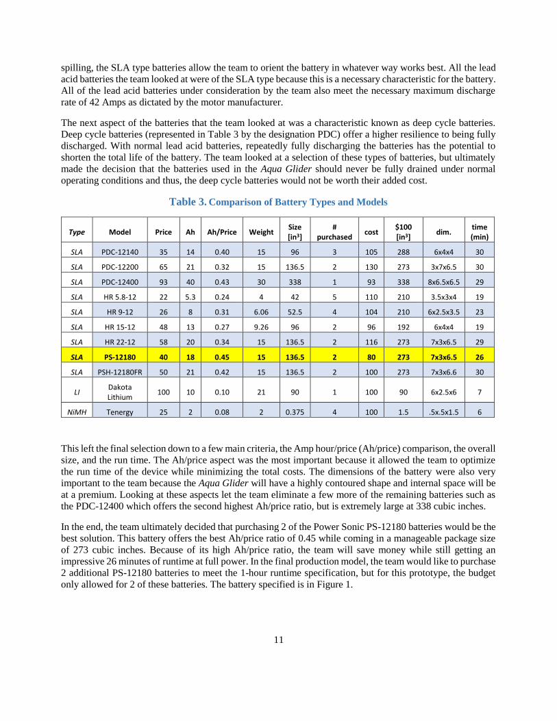
only allowed for 2 of these batteries. The battery specified is in Figure 1.
12
https://www.google.com/search?q=powersonic
4.1.4 DESIGN RESEARCH (MOTORS & PROPELLERS)
The research into the electric motors was more or less straightforward. The team began by researching other
DPVs on the market and finding what size motors they used. In general, the largest motor on any other DPV
was 400 Watts. Similar 400 Watt motors can be found for less than $70 each and are no larger than 4" diameter
by 4" in length. However, as the team encountered a lot of difficulty when they looked into waterproofing
solutions for the custom motor and propeller designs. These concerns were confirmed when the shop manager
Phil Jaspers shared with us the difficulty of waterproofing custom components. [5]
4.1.5 DESIGN CONSIDERATIONS & ALT.
As an alternative, both the shop manager Phil Jaspers and the team’s technical consultant Prof. Tubergen
independently suggested adapting trolling motors to fit the design. Trolling motors provided a motor, prop
shaft, and propeller all packaged together in one waterproof case. In addition to this, the manufacturers spec
exactly how much thrust each motor is capable of producing. This allows the team to simply purchase the
motors that will provide enough thrust to overcome all of the drag forces on the vehicle and reach the target
velocity. Lastly, trolling motors come with built in speed controllers. This is beneficial to the team because
they will simply need to adapt the controls to fit the new application instead of purchasing the necessary
parts to control the speed of the vehicle.
4.1.6 DESIGN DECISIONS
Once the team had decided trolling motors were the solution they wanted to pursue, research was done into
what type of trolling motor was needed. The most important factor in choosing the motors was the cost.
Trolling motors can easily be found at prices exceeding $3000. This was far outside the team’s budget, so
much less expensive solutions needed to be found. The most common of these less expensive motors were
found from the manufacturer Minn Kota. Minn Kota offers a full range of high quality motors at varying
power levels between 30 and 100 lbf of thrust for prices between $100 - $250 based on power output. The
team also looked at another motor from the manufacturer Goplus, although very little information about this
motor or the manufacturer in general was available.
From these two manufacturers, three motors were chosen that fit within the budget. In order to decide between
these 3, a decision matrix was made and can be seen as Table 4.
Figure 1. Power Sonic PS-12180 Battery

13
Table 4. Trolling Motor Decision Matrix
Cost Ease of
Implementation Information Build Quality
Power Consumption
Power Total
Weight 9 3 6 3 7 9 --
Minn 30 7 8 9 8 8 4 --
63 24 54 24 56 36 257
Minn 40 5 8 9 8 7 7 --
45 24 54 24 49 63 259
Goplus 86 5 6 4 5 5 10 --
45 18 24 15 35 90 227
After studying the results of the decision matrix and ensuring the weights for each characteristic were
appropriate, the team decided that the Minn Kota Endura C2 40 was the best decision. The trolling motor can
be seen in Figure 2. This motor provides sufficient power at a reasonable price point from a trusted
manufacturer.
https://i5.walmartimages.com/asr/9940b4bc
4.2 BOUYANCY
4.2.1 DESIGN RESEARCH
In order for the tandem of the DPV and the diver to function properly both the diver and the DPV must achieve
neutral buoyancy. The diver achieves neutral buoyancy through the utilization of a buoyancy control device
(BCD) and weight belt. The weight belt initiates the diver’s descent into the water and the BCD helps to
control the buoyancy under the water. The device operates through siphoning some of the compressed air
Figure 2. Minn Kota Endura C2 40 Trolling Motor

14
from the diver’s air supply to increase the volume of a bladder, increasing the displacement and directly
impacting the buoyant force. Releasing the air causes a decrease in buoyant force and can result in the diver
sinking to lower depths. Bladders do not require large volumes of air to alter buoyancy. Simply breathing
and filling the volume of the diver’s lungs is enough to affect their buoyancy. Therefore, the slightest
alterations in the volume to weight ratio can have significant effects on buoyancy. Neutral buoyancy is achieved for a DPV when the density of water is equal to the average density of the DPV.
Additionally, Archimedes principle plays an important role in the determination of the buoyant force that acts
on an object. Archimedes principle states that the buoyant force acting on an object is equal to the weight of
water that is displaced by that particular object. Therefore, the weight of the device must equal the buoyant
force to achieve neutral buoyancy. Using these two principles, there are ways to accommodate for, and ensure
that the Aqua Glider achieves neutral buoyancy. However, it is often better for underwater vehicles to remain
slightly positively buoyant in the event that the device fails. Additionally, it is always easier to add weight
than it is to take weight away. “As a general rule for small vehicles, the buoyant force should be designed as
4% more than the weight of the vehicle. Weights are then added to bring the buoyant force to within 1 – 2%
of the submerged weight” [6]. The center of buoyancy is also an important consideration. The center of
buoyancy is equal to the center of gravity of the displaced liquid.
4.2.2 DESIGN CONSIDERATIONS & ALT.
Trim Weights
One option to compensate for buoyancy is to design the vehicle positively buoyant and then add the necessary
weight to achieve neutral buoyancy. Having adjustable weight attachments will allow for the accommodation
of different aquatic environments that have different density characteristics. Trim weights are generally
disposable by many divers and can be released to quickly resurface. However, while it is a low risk and
relatively simple solution it doesn’t allow for mid-dive buoyancy alterations.
Ballast Design
A second option that is used on many submarines involves the use of a ballast tank. This would help the DPV
achieve neutral buoyancy and then more water can be added to establish a negative buoyant force. Resurfacing
and positive buoyancy are accomplished through the use of compressed air to expel water out of the tank,
lowering the vehicle’s weight and consequently, the vehicle’s average density. Although, on large submarines
compressed air is contained on board, one consideration for the Aqua Glider is to use a mechanical system to
expel water out of the tank. Additional mechanical systems that could be used on smaller underwater devices
include a mechanical extension and retraction of a piston rod. This piston rod could be used to either be
manually operated by the diver himself or through a gear and actuator. Ballast tanks are a useful for mid-dive
adjustments.
4.2.3 DESIGN DECISIONS
Team 26 will first plan to implement the method of adding trim weights to the vehicle to achieve neutral
buoyancy. This method provides the simplest solution to the problem and is an established practice already
used by divers. In the event that there is extra time at the end of the project, the team will use two air cylinders
that are operated through a small motor actuator and set of worm gears to operate a ballast tank. The cylinders
the team plans to use are found in Figure 3. This will allow the diver to make on board fine tune adjustments
at shallow depths before descending. To eliminate the number of moving components and the need to
waterproof, the team selected to use a motor and worm gear for their ease of operation and reliability.
15
Figure 3. Parker Pressurized Cylinder
HTTP://CDN.MSCDIRECT.COM/GLOBAL/IMAGES/PRODUCTIMAGES/8549589-23.JPG
4.3 HYDRODYNAMICS
4.3.1 DESIGN RESEARCH
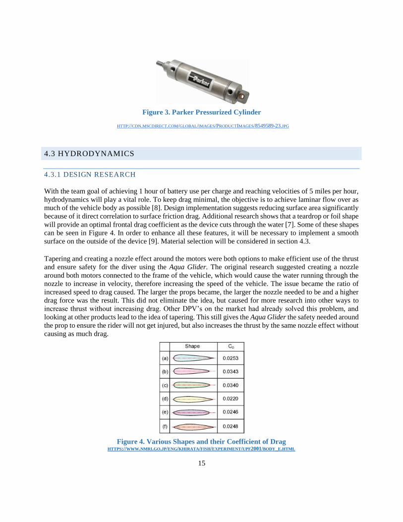
With the team goal of achieving 1 hour of battery use per charge and reaching velocities of 5 miles per hour,
hydrodynamics will play a vital role. To keep drag minimal, the objective is to achieve laminar flow over as
much of the vehicle body as possible [8]. Design implementation suggests reducing surface area significantly
because of it direct correlation to surface friction drag. Additional research shows that a teardrop or foil shape
will provide an optimal frontal drag coefficient as the device cuts through the water [7]. Some of these shapes
can be seen in Figure 4. In order to enhance all these features, it will be necessary to implement a smooth
surface on the outside of the device [9]. Material selection will be considered in section 4.3. Tapering and creating a nozzle effect around the motors were both options to make efficient use of the thrust
and ensure safety for the diver using the Aqua Glider. The original research suggested creating a nozzle
around both motors connected to the frame of the vehicle, which would cause the water running through the
nozzle to increase in velocity, therefore increasing the speed of the vehicle. The issue became the ratio of
increased speed to drag caused. The larger the props became, the larger the nozzle needed to be and a higher
drag force was the result. This did not eliminate the idea, but caused for more research into other ways to
increase thrust without increasing drag. Other DPV’s on the market had already solved this problem, and
looking at other products lead to the idea of tapering. This still gives the Aqua Glider the safety needed around
the prop to ensure the rider will not get injured, but also increases the thrust by the same nozzle effect without
causing as much drag.
Figure 4. Various Shapes and their Coefficient of Drag HTTPS://WWW.NMRI.GO.JP/ENG/KHIRATA/FISH/EXPERIMENT/UPF2001/BODY_E.HTML
16
4.3.2 DESIGN CONSIDERATIONS & ALT.
The team had to consider internal components and how everything will fit inside the shell when designing
the device. The shape of the device directly affects how the components will be oriented and their
functionality within the body cavity. Delightful harmony is also a consideration in the design, where the team
desires the device to have resemblance to a natural aspect of an aquatic environment. There is deliberation
with respect to the control surfaces of the device and how they play a role in the hydrodynamic aspect of
DPV. Another idea was to use the diver as the control surface, reducing the devices surface area and directly
boosting both efficiency and battery life.
4.3.3 DESIGN DECISIONS
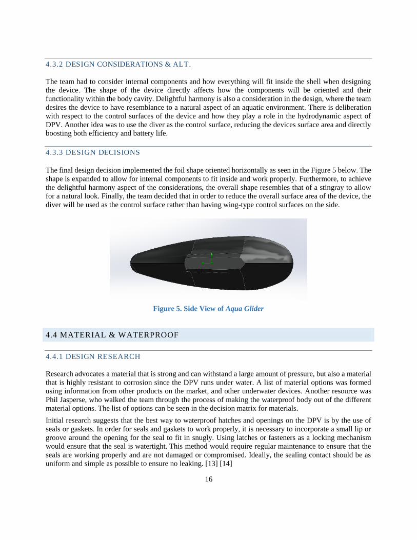
The final design decision implemented the foil shape oriented horizontally as seen in the Figure 5 below. The
shape is expanded to allow for internal components to fit inside and work properly. Furthermore, to achieve
the delightful harmony aspect of the considerations, the overall shape resembles that of a stingray to allow
for a natural look. Finally, the team decided that in order to reduce the overall surface area of the device, the
diver will be used as the control surface rather than having wing-type control surfaces on the side.
Figure 5. Side View of Aqua Glider
4.4 MATERIAL & WATERPROOF
4.4.1 DESIGN RESEARCH
Research advocates a material that is strong and can withstand a large amount of pressure, but also a material
that is highly resistant to corrosion since the DPV runs under water. A list of material options was formed
using information from other products on the market, and other underwater devices. Another resource was
Phil Jasperse, who walked the team through the process of making the waterproof body out of the different
material options. The list of options can be seen in the decision matrix for materials.
Initial research suggests that the best way to waterproof hatches and openings on the DPV is by the use of
seals or gaskets. In order for seals and gaskets to work properly, it is necessary to incorporate a small lip or
groove around the opening for the seal to fit in snugly. Using latches or fasteners as a locking mechanism
would ensure that the seal is watertight. This method would require regular maintenance to ensure that the
seals are working properly and are not damaged or compromised. Ideally, the sealing contact should be as
uniform and simple as possible to ensure no leaking. [13] [14]

17
One issue that arises depends on if the hatch shape is non-circular. A gasket would then be the ideal solution.
They can be made of the same material as O-rings, but gaskets are more specified for irregular shapes. With
that in mind and coinciding with the fact that a circular hatch will distribute the pressures more evenly, the
hatch shape will be a 6-inch diameter circular hole to provide the best waterproofing capability.
Shaft sealing was another researched topic for underwater vehicles. When first designing the Aqua Glider the
team thought that they may need to use a bevel gear to attach the electric motor inside the frame to the prop
outside the frame and seal a shaft exiting the frame. In using trolling motors, that type of seal was no longer
needed, but the same research may be implemented when putting in handles for the vehicle. A pump shaft
seal would be used because it seals a shaft extremely well by becoming a tighter and tighter seal as the pressure
increases. This is perfect for a DPV because as the diver goes deeper the pressure increases.
4.4.2 DESIGN CONSIDERATIONS & ALT.
The need for a watertight seal, and an easy usability for contour played a large role in the design. Talking to
Phil Jasper it became clear any metal would be extremely difficult to contour and waterproof. Welding thin
metal is very difficult to seal and with the DPV being submerged in water, it would cause the device to have
a lot of places where water could potentially leak in. The team needs a process that allows us to design a
frame for the device and use the frame to place the material around it to obtain the hydrodynamic contour.
In avoiding the need for too many access points for maintenance, trolling motors are specified as opposed to
using an electric motor that would need to be secured within the housing. This eliminates the need for
maintenance access points at the motors, and gives the system only one access point for maintenance inside
the frame.
There are multiple different types of O-ring material that can be applied to the device including Nitrile,
Ethylene-Propylene, Silicone, and Neoprene. Each one provides variation on sealing capabilities, from
resistance to degradation, temperature stability, and compression set. In order to be completely watertight,
the seal needs an ingress protection rating of IP68 which means that it has protection against the effects of
immersion in water under pressure for long periods. [10] [11] [12]
4.4.3 DESIGN DECISIONS
Material options for a process using a frame and applying the material around it included fiberglass, carbon
fiber, PVC and HDPE. Both PVC and HDPE are inexpensive, but their durability and need for machining
made them poor choices. In the end fiberglass is less expensive than carbon fiber, and is a strong material,
providing the best choice. A Nitrile O-ring is chosen for sealing due to its resistance to fluids found on typical vehicles including
petroleum, oils, greases, water and alcohol. It has one of the highest performance to cost ratings and its only
limitation is that it contains a small amount of ozone that can slightly weaken plastics. Overall, it has all the
properties necessary to seal out water and a good cost outlook for the consumer.
4.5 CONTROLS
4.5.1 DESIGN RESEARCH
There are multiple major movement classifications that are used to control an underwater vehicle. Sway,
pitch, roll, heave, yaw and surge as defined by Figure 6. Most current DPV’s focus solely on mechanical

18
control of surge and buoyancy. On most of the DPV’s, surge is controlled through a single, variable speed
propeller while the heave is controlled primarily through the buoyancy systems mentioned in section 4.1.2.
The remaining movements are user generated through the twisting and turning of the diver’s body. On other
underwater vehicles like submarines, pitch can be automated through the use of hydroplanes. Hydroplanes
are control surfaces that alter their angle of rotation to redirect the water flow. This generates forces on the
hydroplanes that either induce lift or descent of the vehicle. To control yaw many aquatic vehicles will make
use of a rudder. A rudder, similar to a hydroplane, is a control surface that is able to redirect the flow of water
to generate the force that allows the vehicle to have turning capabilities.
Figure 6. Submarine Dynamics
http://scialert.net/fulltext/?doi=jas.2014.991.999&org=11
4.5.2 DESIGN CONSIDERATIONS & ALT.
Team 26, with its two propeller design, is able to consider a new aspect of the design that many of the other
vehicles overlook. Two variable speed propellers integrate the impact of having the machine do the steering.
The operator can accelerate the propeller on one side of the device and slow the other to turn in the desired
direction using tank steering guidelines. This is accomplished with the DC motors by simply increasing the
voltage to the motor that the diver wants to spin faster.
One consideration for depth change variation considered, was to place a rotating rod through the DPV that
could tilt the motors up or down. However, considering the added complexity associated with adding the
feature, the team decided it did not make sense to implement it. For depth changes, the Aqua Glider will
depend on point-and-shoot operation, where the operator points the front end in the direction that is desired.
It is a solution that provides the simplest operation while minimizing the risk of flooding or control failure
for the prototype.
4.5.3 DESIGN DECISIONS
The two-handed throttle design will be used for testing purposes, but further in development, a control system
that utilizes a computer interface will be optimized so that the diver may operate the DPV with only one hand.
This allows for a free hand to deal with respirators, tubes, or gauges that the diver needs to be aware of
throughout their excursion.

19
5. PRODUCT DESIGN IMPLEMENTATION
5.1 SYSTEM ARCHITECTURE
To provide power to each of the subsystems, the two 12 volt batteries will be mounted centrally to be as close
to center of mass as possible. In controlling the two main propulsion motors, power will flow from the
batteries through the speed controllers operated by the diver and into the motors on each side of the device.
In order to control the ballast systems, power will flow from the batteries to the buoyancy control switch
separately operated by the diver, and then into the buoyancy actuator. These three controls will provide a full
range of maneuverability to the diver. The diver will be able to thrust both forwards and backwards, yaw left
and right by operating the motors and different rates, and rise up and down by filling or emptying the ballast
tanks. An overview of the system is found in Figure 7.
Figure 7. System Architecture for the Aqua Glider
5.2 CAD & 3D MODELING
The final hydrodynamic shape the team will resemble in their prototype can be seen in the Solidworks
generated model that is seen in Figure 8. As mentioned earlier, the design was built on the premises of an
organic shape. The top view loosely resembles that of a manta ray. Meanwhile, the side profile was crafted
into the shape of an airfoil to achieve the hydrodynamic shape that was specified. The gross overall
dimensions of the Aqua Glider include a 30-inch length from tip to tail, 10 in from the bottom of the hull to
the top of the hull and 34 in. from the center of one trolling motor to center of the other, with 11.5-inch
diameter ducts to accommodate the rotating propellers. The 10 in. height provides sufficient room for the 3
in. height battery cell attachments. Using the mass properties tool in SolidWorks the Aqua Glider (including
the modeled trolling motors) was found to be 1.4 ft3 with a surface area of 20.7 ft2. Additionally, between
the ducted portions of the Aqua Glider Shell is nearly a two-foot space that allows room for the diver to rest
his forearms and operate the “point and shoot controls”. Control throttle handles will be extended from the
shell of the vehicle near the front of the model to provide a contact point for the diver to control the vehicle.
Overall, the Solidworks model provided a visual for the team to attain an understanding of the space that

20
can be utilized within the context of the frame. The solution provides sufficient room for holding all internal
components while maintaining a hydrodynamic shape.
Figure 8. CAD Model of the Aqua Glider
To test the effectiveness of the hydrodynamic shape the team conducted an external computational flow
dynamics (CFD) analysis in Solidworks. This gave the team the ability to estimate a value for the drag
coefficient and drag force to be used in the thrust determinations. However, the team wanted to first establish
trust in the program. The programs’ reliability was tested running analysis that compared the drag
coefficients of known geometries by the program to that of the known coefficient for that particular shape.
The program verified that it was able to adequately produce the drag force and coefficients of the known
geometries. Running the analysis on the model shown in Figure 8 revealed that the drag force of the vehicle
experienced at 5 mph underwater was 23.75 lbf. The program output for the drag force can be seen in Figure
9. Using the frontal area of the DPV, as estimated in the Solidworks file to be 1.36 ft2, calculated the drag
coefficient of the vehicle to be 0.33. While this was a simplified analysis and doesn't account for the
extension of the control handles or the propeller, this provides a good basis for the estimated drag of the
Aqua Glider. A correction factor was added in the thrust calculations to take such simplifications into
account.
Figure 9. CFD Results
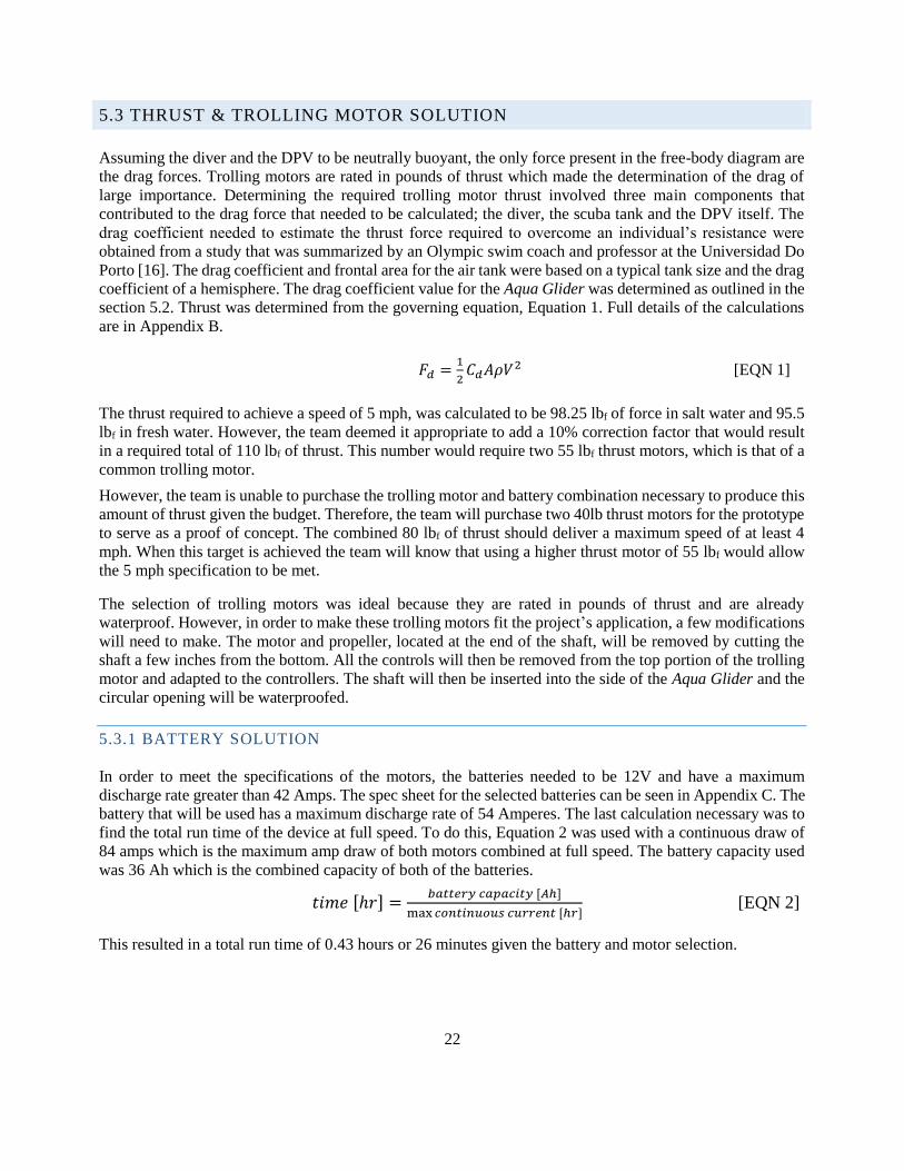
The CFD allowed the team to observe the flow over the body of the DPV to ensure a desired flow of fluid.
The CFD results yielded the velocity trajectory graphic in Figure 10 and a pressure cut plot in Figure 11.
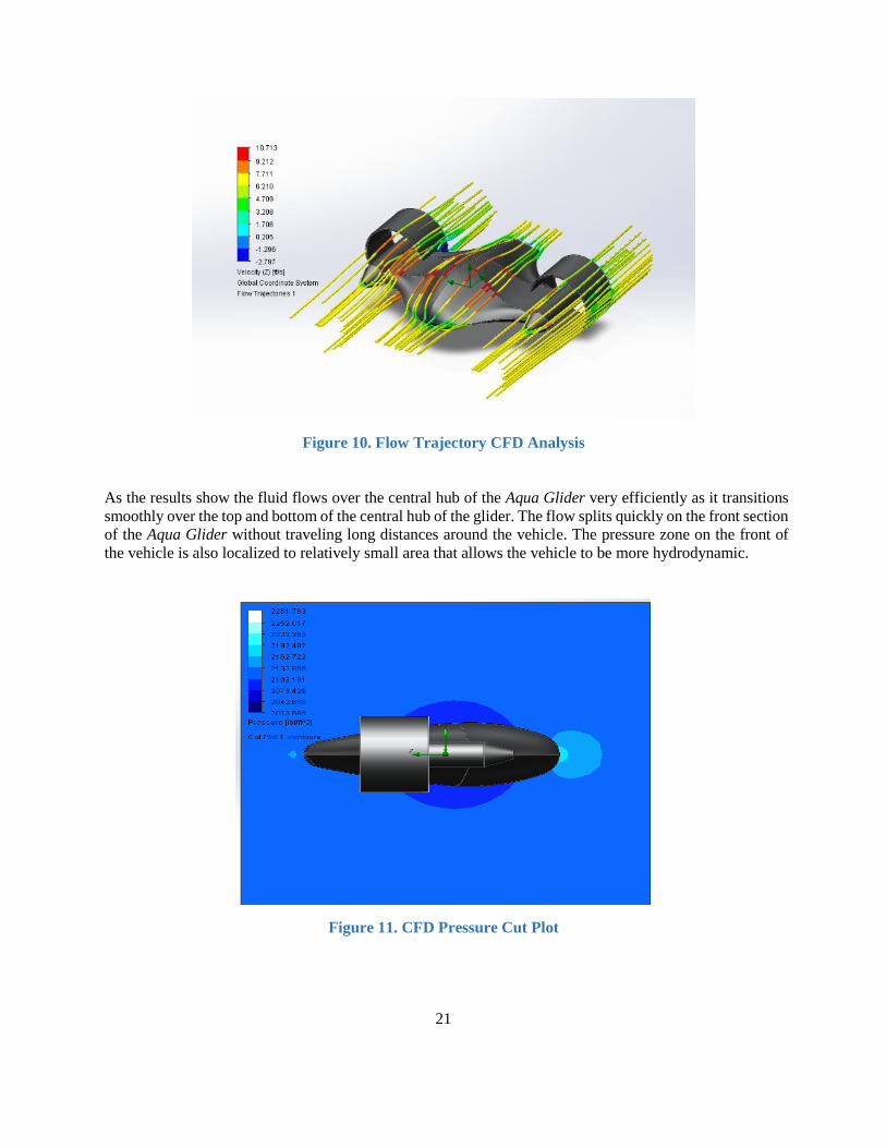
21
As the results show the fluid flows over the central hub of the Aqua Glider very efficiently as it transitions
smoothly over the top and bottom of the central hub of the glider. The flow splits quickly on the front section
of the Aqua Glider without traveling long distances around the vehicle. The pressure zone on the front of
the vehicle is also localized to relatively small area that allows the vehicle to be more hydrodynamic.
Figure 10. Flow Trajectory CFD Analysis
Figure 11. CFD Pressure Cut Plot
22
5.3 THRUST & TROLLING MOTOR SOLUTION
Assuming the diver and the DPV to be neutrally buoyant, the only force present in the free-body diagram are
the drag forces. Trolling motors are rated in pounds of thrust which made the determination of the drag of
large importance. Determining the required trolling motor thrust involved three main components that
contributed to the drag force that needed to be calculated; the diver, the scuba tank and the DPV itself. The
drag coefficient needed to estimate the thrust force required to overcome an individual’s resistance were
obtained from a study that was summarized by an Olympic swim coach and professor at the Universidad Do
Porto [16]. The drag coefficient and frontal area for the air tank were based on a typical tank size and the drag
coefficient of a hemisphere. The drag coefficient value for the Aqua Glider was determined as outlined in the
section 5.2. Thrust was determined from the governing equation, Equation 1. Full details of the calculations
are in Appendix B.
𝐹𝑑 =1
2𝐶𝑑𝐴𝜌𝑉2 [EQN 1]
The thrust required to achieve a speed of 5 mph, was calculated to be 98.25 lbf of force in salt water and 95.5
lbf in fresh water. However, the team deemed it appropriate to add a 10% correction factor that would result
in a required total of 110 lbf of thrust. This number would require two 55 lbf thrust motors, which is that of a
common trolling motor.
However, the team is unable to purchase the trolling motor and battery combination necessary to produce this
amount of thrust given the budget. Therefore, the team will purchase two 40lb thrust motors for the prototype
to serve as a proof of concept. The combined 80 lbf of thrust should deliver a maximum speed of at least 4
mph. When this target is achieved the team will know that using a higher thrust motor of 55 lbf would allow
the 5 mph specification to be met.
The selection of trolling motors was ideal because they are rated in pounds of thrust and are already
waterproof. However, in order to make these trolling motors fit the project’s application, a few modifications
will need to make. The motor and propeller, located at the end of the shaft, will be removed by cutting the
shaft a few inches from the bottom. All the controls will then be removed from the top portion of the trolling
motor and adapted to the controllers. The shaft will then be inserted into the side of the Aqua Glider and the
circular opening will be waterproofed.
5.3.1 BATTERY SOLUTION
In order to meet the specifications of the motors, the batteries needed to be 12V and have a maximum
discharge rate greater than 42 Amps. The spec sheet for the selected batteries can be seen in Appendix C. The
battery that will be used has a maximum discharge rate of 54 Amperes. The last calculation necessary was to
find the total run time of the device at full speed. To do this, Equation 2 was used with a continuous draw of
84 amps which is the maximum amp draw of both motors combined at full speed. The battery capacity used
was 36 Ah which is the combined capacity of both of the batteries.
𝑡𝑖𝑚𝑒 [ℎ𝑟] =𝑏𝑎𝑡𝑡𝑒𝑟𝑦 𝑐𝑎𝑝𝑎𝑐𝑖𝑡𝑦 [𝐴ℎ]
max 𝑐𝑜𝑛𝑡𝑖𝑛𝑢𝑜𝑢𝑠 𝑐𝑢𝑟𝑟𝑒𝑛𝑡 [ℎ𝑟] [EQN 2]
This resulted in a total run time of 0.43 hours or 26 minutes given the battery and motor selection.

23
5.4 BOUYANCY SOLUTION
The dimensions of the shell of the Aqua Glider in addition to all other factors that created an external volume
that displaced water were key considerations in the determination of the buoyancy force. The simple
Equation 3 served to define the mass of the vehicle that would be necessary to attain neutral buoyancy.
𝑊 = 𝑉 𝑒𝑥𝑡 𝜌𝑔 [EQN 3]
It was determined that mass of Solidworks model that had an external volume of 1.774 shown in Section 5.2
was required to be 111 lbf for fresh water and 114 lbf for salt water. To achieve a desired weight, the vehicle
required several redesigns of the Solidworks model to eliminate external volume to achieve a required
vehicle weight that met specifications. The buoyancy calculations and process of refining the volume can be
seen in Appendix D. As the team continues to move into the next stage of the design process, they will
continue to look for ways to reduce the external volumes without sacrificing function or significantly altering
aesthetics. To determine the additional weight that is required to be added to the system the weights of the current
system were utilized. Using a density of 0.55 lbf/in3 the weight of the fiber glass frame was calculated at 0.5
in thickness resulted in the shell having a weight of 4.5. The other components were estimated based on their
shipping weights or specifications.
Table 5. Component Weight and Volume Contribution
Subsystem Part Weight Ext. Volume Contribution
Power/Propulsion Motors (2) ≈ 15 lbf each ≈0 .101 ft3 Power/Propulsion Batteries (2) 15 lbf each 0.158 ft3
Buoyancy Pistons (2) ≈ 2 lbf each TBD Buoyancy Motor (1) < 1 lbf TBD Structural Fiberglass Shell ≈ 4.5 lbf ≈ 1.57 ft3 Structural Al. Frame TBD negligible
Total Weight and External Volume 66.5 lbf 1.77 ft3 DPV Avg. Density 37.6 lbf /ft3
From Table 5 above, it was determined that 44.5 lbf of weight will be required to be added in fresh water
and 47.5 lbf in saltwater achieve neutral buoyancy. This is an adequate number because the team will be able
to add more battery cells (if the extra funds are found) and a frame to the system. This also leaves room for
the feasibility of lead trim weights that will allow for variable buoyancy controls in the system. Underwater,
on board fine tune adjustments of the buoyancy are often required and the team has decided to use a system
of air cylinders that will operate as ballast tanks. This will allow the diver to submerge the vehicle and at
depth of 10-15 feet make buoyancy adjustments for the remainder of the dive. A system that uses two 2”
bore and 6” stroke pistons similar to that of those produced by Parker, will allow for 1.36 lbf in fresh water
and 1.4 lbf in salt water of variable buoyancy alterations. The end of the air cylinder will be machined off to
allow for water to flow in and out. The team plans to do small scale tests as the design moves forward to
determine if larger cylinders will be required.
24
5.5 MATERIAL SOLUTION
Fiberglass has a yield strength of about 30,000 psi, compared to Aluminum at 35,000 psi, which is within
20% of the strength [2]. The fiberglass frame may not be strong enough to withstand the pressure of a dive
on its own, but it can be layered for thickness to increase strength and an Aluminum frame can be
implemented to provide sufficient strength for the shape of the Aqua Glider.
The process of laying fiberglass includes the use of a foam frame and layering for strength. The frame of the
Aqua Glider will be made of Styrofoam, cut to exact measurements by the CNC machine in the Machine
Shop. Fiberglass is a very flexible material, but when the poly resin is applied a firm shape is developed. To
make the device, the first step is to define the dimensions of the foam pattern, keeping in mind the added
thickness from the fiberglass and the total needed space inside the frame. After the foam is created, the resin
and hardener are mixed and applied to the fiberglass cloth around the foam pattern, ensuring a thick coating
by reapplying. Based on market research, other DPVs use Aluminum shells to withstand depths much deeper
than the Aqua Glider will need to go. Because of the similarity in strength of fiberglass and Aluminum the
team is confident that the fiberglass shell will be able to withstand the pressures of water at a maximum
depth of 130 feet. After the fiberglass is complete, an internal Aluminum frame will be constructed. The
exact details for the inside frame will be assessed in second semester. The fiberglass will give us the ability
to have the contours specified and the desired aesthetics at a low cost. It does have a rough finish, but will
give us a great proof of concept for the shape and contour of the prototype.
25
6. BUSINESS PLAN
6.1 MARKET RESEARCH
According to a study conducted by the Diving Equipment & Marketing Association (DEMA) in 2014, there
are somewhere between 2.7 and 3 million active recreational scuba divers in the United States (140,000 new
divers per year) and around 6 million active divers worldwide that serve as the market basis for the Aqua
Glider. According to the same study, the average age of a scuba diver is around 30 years. Additionally, 64%
of divers have an annual income between $100,000 and $150,000. There is about $11 billion dollars in
recreational scuba and snorkeling that add to the US GDP. The total average revenue made off a scuba diver
is $1,910. With high concerns, the scuba market is saturated with products that are designed for quality. While
quality doesn’t always insinuate an increase in price, the Scuba market definitely is not an inexpensive
recreational activity. Table 1 gives an estimate for the prices of essential gear components. Therefore, while
minimizing cost is a concern for the Aqua Glider, the performance and quality of the vehicle should not be
traded off. [15]
6.2 COMPETITIVE STRATEGY
The Aqua Glider is not the only scuba mobility solution on the market, therefore the team did extensive
research into a number of other DPV products. A tabulated and graphical summary of the results can be found
in Appendix F. Through the comparison of many different products, it was determined that in order to give
the Aqua Glider a competitive edge, it must be capable of speeds higher than other DPVs while still
maintaining the runtime and depth rating that are characteristic of recreational dives. Another key component
is providing the Aqua Glider with navigational controls, to minimize the body movement necessary to turn
the DPV; an innovative part of the solution not seen on most current DPV’s. Largely, the Aqua Glider is
being developed to set a new level of control and speed in the DPV market.
6.3 SWOT ANALYSIS
6.3.1 STRENGTHS
The Aqua Glider provides a recreational diver with a unique and new hydrodynamic shape that will
accommodate dual propellers for speeds higher than most of the competitor DPV’s. Divers looking for more
power out of a DPV will be drawn to the Aqua Glider. The dual propeller also allows for a more dynamic
turning control feature. The turning controls will be less cumbersome to the diver as he attempts to maneuver
under water. DPV’s allow for divers to explore greater distances more efficiently, and therefore appeal to
many divers looking to explore a larger area while exerting less energy and using less oxygen to do so.
6.3.2 WEAKNESSES
The Aqua Glider is going to be larger and wider than many of the DPV’s that have been developed. This is a
tradeoff the team considered to achieve the extra power, however divers looking to explore spaces with tighter
features may shy away from the Aqua Glider. Furthermore, DPV’s have a learning curve associated with their

26
operation and consequently, non-frequent divers may not justify the learning time required by a DPV worth
the investment.
6.3.3 OPPORTUNITIES
Divers are willing to spend money in a market where flippers alone can cost upwards of $200, dive suits
around $500, and regulators around $300. Therefore, there is a strong client basis willing to spend money on
high quality, specialty operational products. Developing the Aqua Glider could also motivate companies to
come up with competitive products, pushing DPV technology to new levels.
6.3.4 THREATS
The recreational activity of Scuba for most people requires that they either have access or have the financial
means to travel to a body of water. The market is relatively narrow and fluctuates based on the economy more
than many other products because it is considered a luxury item. Environmental threats also need to be
considered as contamination of diving sites through pollution or other environmental factors may take some
of the allure of recreational diving away. The presence of other DPV’s on the market may distract divers from
selecting the Aqua Glider.
6.3 COST ESTIMATE
6.3.1 DEVELOPMENT
Calvin College has granted the Aqua Glider team with a budget of $500, and cost breakdown for the prototype
components and the testing of the machine can be found in Table 1. The team does have access to a limited
amount of material from the Calvin College machine shop and the storage facility from past years’ projects.
6.3.2 PRODUCTION
Part of the business plan for the Aqua Glider is to take the development and prototype and eventually scale
the project up for higher quantity production. The scale of production will be at the lower end as a DPV is a
specialty device and is not used by every diver. The production of the product should also be flexible to
account for accommodating new markets, in the case that the Aqua Glider is something that could have
eventual military applications.
6.3.3 DISTRIBUTION
DEMA’s research has discovered that the top four diving states in the US are California, Florida, Texas, and
New York, respectively. Consequently, the Aqua Glider will have offices and distribution centers along the
coastlines of each of these states and the dive sites. The team hopes to see the Aqua Glider make its way into
many of the dive shops at these locations. A large portion of the distribution of the Aqua Glider will also be
conducted through online retail.

27
7. CONCLUSION
7.1 POTENTIAL RISKS AND ISSUES
Throughout the planning, designing, and developing of the Aqua Glider, multiple different issues and risks
will arise. Team 26 has prepared for such problems by predicting how and when they will show up.
Buoyancy is the biggest risk with the Aqua Glider as there are a vast number of ways in which the device
can have failures in this regard. The first issue arises with design for buoyancy. If the DPV has to large of
a volume, it will take a lot of weight just to get it to sink. On the other hand, if it’s volume is too small or
hatches and holes are not waterproofed, the Aqua Glider could sink and become completely useless. The
idea is to neutralize buoyancy effects with the addition of ballast tanks. Another potential issue that the
team has taken into account is the controls interface. The team has a general lack of knowledge when it
comes to setting up the controls system, but will close the gap during construction and prototyping. Since
the device uses dual variable motors, there is the potential that the controls do not work independently when
they are attached to a single power source. The controls also leave room for error in waterproofing. For
operation, a throttle system will need to be integrated into the handle and there needs to be a port for the
wiring to go inside the DPV. The next major potential issue is the internal access hatch necessary to reach
the batteries and internal components. The hatch would provide a waterproofing challenge as it would be
relative large and provide the biggest risk to the integrity of the Aqua Glider. The problem with the hatch
is that as the hole becomes larger, the forces associated at depths become larger as well. Finally, overall
integration of the Aqua Glider provides multiple problems with regard to getting all the components to
work together as one cohesive unit.
7.2 PROJECT STATUS
The team has made major decisions regarding key aspects to the Aqua Glider and is on track to have a full
scale and functioning model built by the spring for live testing and analysis. The biggest decision is the
implementation of two variable speed motors. Most DPV’s on the market today only have one motor and
using two gives the Aqua Glider the potential to be the fastest and most controllable vehicle on the market.
Along those lines, Team 26 has chosen to use trolling motors because of the reduction in risk associated
with designing and waterproofing custom motor housings. Additionally, adding ducts to the propellers
reduces the tip vortices and boosts efficiency. CAD models have integrated the contoured design discussed
earlier to be hydrodynamic, functional, and integrated with the surroundings. The Aqua Glider has adopted
the foil profile along with a stingray-like contour into the design, making it as aesthetically pleasing and
functional as possible. The project is developing on schedule. Part procurement and construction is set to
begin in January 2017.
7.3 PROJECT FEASIBILITY
As with many enterprises, the scope of the project must be taken into account. The initial approach included
multiple aspects that are not possible to merge in the design given the time and monetary constraints. If the
team had more time and funds, higher powered custom motors would be included to guarantee that the goal
of 5 mph cruising speed would be reached. Furthermore, the ideal situation would allow for additional
lithium-ion batteries to allow for longer dive times. The Aqua Glider would also include higher technology
components such as headlights and navigation capabilities. Members of the dive community are very
invested in their hobby and are willing to spend their resources on it. Therefore, the cost of the device did
not play a very large role in the vehicle development. Overall, the team has cut out the unnecessary “luxury”

28
features initially considered in order to make sure that the device functions. Any extra time at the end of
the semester will be put toward adding those features.
7.4 SUMMARY
Overall, the Aqua Glider is on track to have a working prototype by the spring. Team 26 will continue to
utilize each member’s skills and talents to develop a DPV that is functional, safe, and fun to use. The team
has predicted issues that may arise and has gotten past some major obstacles already. Nonetheless, others
will surely come up and the team will be prepared for them. The team will strive to incorporate design
norms and bring honor to both God and Calvin College through the accomplishments achieved with the
Aqua Glider.

29
8. ACKNOWLEDGEMENTS
Team 26 would like to cordially thank all their supporters, friends and family for their support over the
year here at Calvin and through the duration of this project. There are a few names we would like to
specifically mention:
Team Advisor: Professor Renard Tubergen
Professor Tubergen has invested in the development of the team as engineers and individuals through the
courses he has taught. Professor Tubergen also served as a technical and moral support for this project.
The team would also like to thank him for the taking the time to instruct us how to scuba dive and being
a well of knowledge
Materials and Design Consultant: Mr. Phil Jasperse
Phil Jasperse has instructed the team the proper mechanics of metal fabrication. He also served as a key
resource for the considerations of the materials and construction that will be implemented into the Aqua
Glider.

30
9. CITATIONS [1] "Understanding Ocean Acoustics." NOAA Ocean Explorer Podcast RSS. NOAA Ocean Explorer Webmaster, 06 Apr. 2015.
Web. 12 Dec. 2016. http://oceanexplorer.noaa.gov/explorations/sound01/background/acoustics/acoustics.html [2] Freitas, Christopher. "SolarPro Magazine." High-Capacity Battery Banks | SolarPro Magazine. Home Power Inc,
2016. Web. 12 Dec. 2016. http://solarprofessional.com/articles/products-equipment/batteries/high-capacity-battery-banks
[3] Wood, T.D. "Batteries: How to Choose." REI. Recreational Equipment, IncRecreational Equipment, Inc, 2016. Web. 12 Dec.
2016. https://www.rei.com/learn/expert-advice/batteries.html [4] "12v or 24v or Something Else? - 4QD - Electric Motor Control." 4QD - Electric Motor Control. 4QD Ltd., 2016.
Web. 12 Dec. 2016.http://www.4qd.co.uk/docs/12-24-36-or-48v-operation/ [5] 24 Volt Electric Scooter and Bicycle Motors - ElectricScooterParts.com. ElectricScooterParts.com, 2016. Web. 12 Dec.
2016.https://electricscooterparts.com/motors24volt.html [6] "Buoyancy, Stability, and Ballast 1 Cornerstone Electronics Technology and Robotics Cornerstone University, n.d. Web. 12
Dec. 2016. http://cornerstonerobotics.org/curriculum/lessons_year3/eriii9_buoyancy1.pdf [7] Hirata, Koichi and Sysuke Kawai. "Prototype Fish Robot, UPF-2001." Hydrodynamic Performance of Stream-lined Body.
N.p., 15 Nov. 2001. Web. 12 Dec. 2016. https://www.nmri.go.jp/eng/khirata/fish/experiment/upf2001/body_e.html [8] Factors That Effect Drag. NASA, 15 May 2015. Web. 12 Dec. 2016. https://www.grc.nasa.gov/www/k-12/airplane/factord.html [9] Shapiro, Thomas A. The Effect of Surface Roughness on Hydrodynamic Drag and Turbulence. N.p., 2004. Web.
12 Dec. 2016. http://www.dtic.mil/dtic/tr/fulltext/u2/a424978.pdf [10] "Material Selection Guide." Nitrile (Buna-N) - Material Selection Guide | Apple Rubber Products. Apple Rubber
Products, n.d. Web. 12 Dec. 2016. http://www.applerubber.com/seal-design-guide/material-selection-guide/nitrile-buna-n.cfm [11] Albert, JD. On-Ramp to Design Engineering: Sealing. Bresslergroup, 13 Feb. 201. Web. 12 Dec. 2016.
http://www.bresslergroup.com/blog/design-engineering-sealing-products/ [12] O-Rings. Apple Rubber, n.d. Web. 12 Dec. 2016. http://www.applerubber.com/products/o-rings.cfm [13] ASM Material Data Sheet. N.p., n.d. Web. 12 Dec. 2016.
http://asm.matweb.com/search/SpecificMaterial.asp?bassnum=MA6061t6 [14] Fiberglass and Composite Material Design Guide. Performance Composites Inc., n.d. Web. 12 Dec. 2016.
http://www.performancecomposites.com/about-composites-technical-info/122-designing-with- fiberglass.html [15] "Fast Facts: Recreational Scuba Diving and Snorkeling." Diving Equipment and Marketing Association (DEMA), 2014. Web.
12 Dec. 2016. http://www.dema.org/store/download.asp?id=7811B097-8882-4707-A160-F999B49614B6 [16] Vilas-Boas, J. Paulo. Hydrodynamics of Drag in Human Swimming. U. Porto, n.d. Web. 12 Dec. 2016.
http://www.fade.up.pt/docentes/leandromachado/biomecanica/Hydrod-Drag.pdf
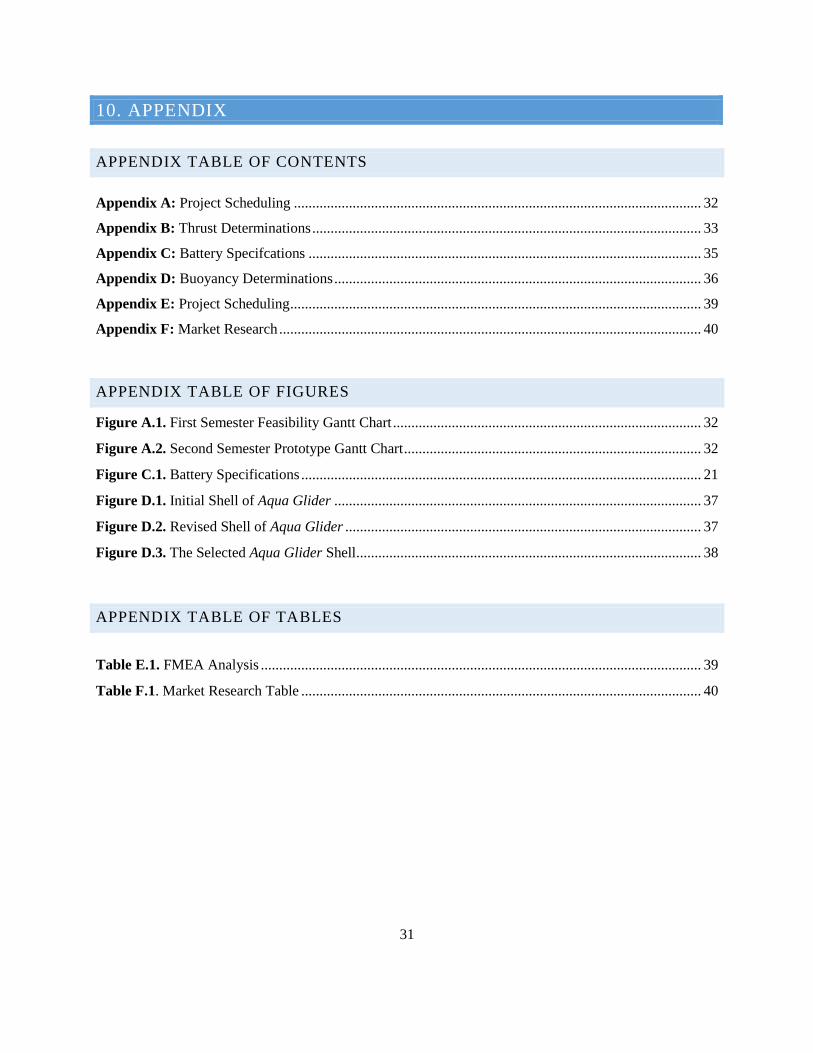
31
10. APPENDIX
APPENDIX TABLE OF CONTENTS
Appendix A: Project Scheduling ............................................................................................................... 32
Appendix B: Thrust Determinations .......................................................................................................... 33
Appendix C: Battery Specifcations ........................................................................................................... 35
Appendix D: Buoyancy Determinations .................................................................................................... 36
Appendix E: Project Scheduling ................................................................................................................ 39
Appendix F: Market Research ................................................................................................................... 40
APPENDIX TABLE OF FIGURES
Figure A.1. First Semester Feasibility Gantt Chart .................................................................................... 32
Figure A.2. Second Semester Prototype Gantt Chart ................................................................................. 32
Figure C.1. Battery Specifications ............................................................................................................. 21
Figure D.1. Initial Shell of Aqua Glider .................................................................................................... 37
Figure D.2. Revised Shell of Aqua Glider ................................................................................................. 37
Figure D.3. The Selected Aqua Glider Shell .............................................................................................. 38
APPENDIX TABLE OF TABLES
Table E.1. FMEA Analysis ........................................................................................................................ 39
Table F.1. Market Research Table ............................................................................................................. 40
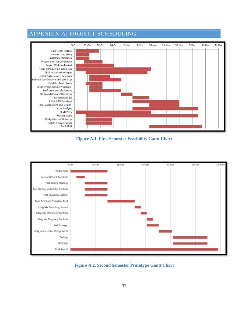
32
APPENDIX A: PROJECT SCHEDULING
Figure A.1. First Semester Feasibility Gantt Chart
Figure A.2. Second Semester Prototype Gantt Chart

33
APPENDIX B: THRUST DETERMINATIONS
34

35
APPENDIX C: BATTERY SPECIFCATIONS
Figure C.1. Battery Specifications
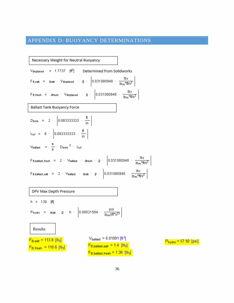
36
APPENDIX D: BUOYANCY DETERMINATIONS
Results
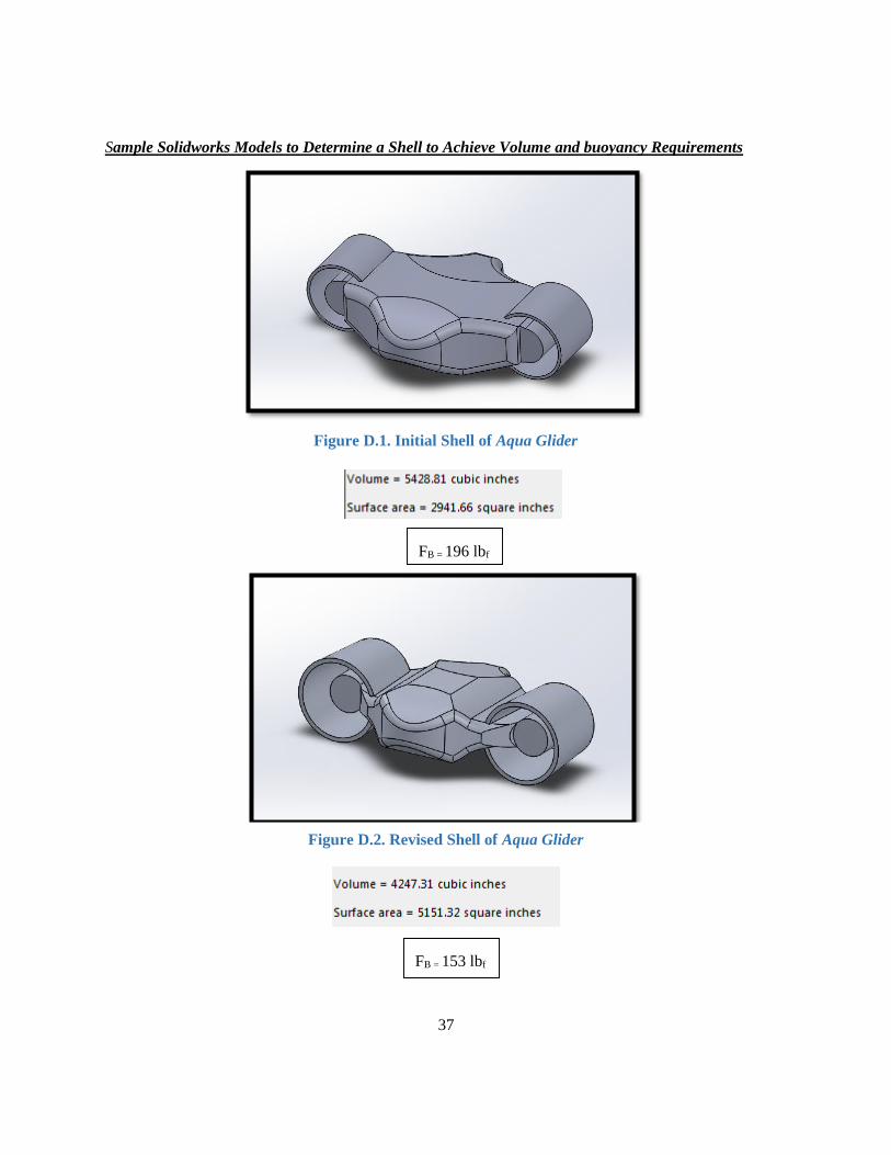
37
Sample Solidworks Models to Determine a Shell to Achieve Volume and buoyancy Requirements
Figure D.1. Initial Shell of Aqua Glider
FB = 196 lbf
FB = 196 lbf
Figure D.2. Revised Shell of Aqua Glider
FB = 153 lbf
FB = 153 lbf

38
Figure D.3. The Selected Aqua Glider Shell
FB = 110 lbf
FB = 110 lbf

39
APPENDIX E: PROJECT SCHEDULING
Table E.1. FMEA Analysis
Function or Process Step
Failure Type Potential Impact
SEV Potential
Causes OCC
Detection Mode
DET RPN
Motor Function: Apply thrust force for
speed
Cannot turn off motors
Vehicle will not stop
8
Trigger gets stuck,
connection signal is
misinterpreted
1 Test each
motor before entering water
2 16
Lacerations
Rotating Propellers
will cut diver
8
Improperly ducted Fans
and diver carelessness
1 Diver Safety Precautions
3 24
Neutral Buoyancy
Buoyancy is not
compensated for
Diver has to fight to
keep device buoyant or
sink
7
Inadequate trim weights or
improper weight balance
of DPV
2
Diver buoyancy test before
descent, regular
maintenance of design
2 42
Battery Function:
Supply power for motors,
ballast tanks, and triggers
The device is unresponsive
Vehicle is no longer functional
7
Water leaks damages the connections,
corrosion, battery is not
charged
3
Test battery responsiveness before entering the water and
perform regular maintenance
3 63
Frame Seal Function: Hold
all parts, withstand
impact, watertight
Water enters the system
Electrical parts fail
and device sinks with
diver attached
10 Seals fail,
causing the vehicle to sink
3 Perform regular
seal maintenance
4 120
Harness Function: Allow
riding to be easier and
more comfortable
Harness breaks
Diver is detached
from vehicle
5
Harness is worn down and
cannot hold force necessary
1
Sight check the harness for any
worn down areas
2 10

40
APPENDIX F: MARKET RESEARCH
Table F.1. Market Research Table
Product Cost Depth
Rating (ft) Power
Speed (MPH)
Battery Life @ Max (hr)
Recharge Time (hr)
Battery Dimensions (in) Weight (lbf)
SEA-DOO® SEASCOOTER™ Aqua Dolphin
$ 209.99 15 --- 2 1.5 N/A 12 V 11.8 x 11.1 x 20.5 12
Sea Doo RS1 Seascooter $ 1,449.00 130 500W 4.35 1.5 7 22 V 24.5x12x12 20.5
Hollis H-160 Vehicle (DPV) $ 3,999.96 656 60 2.4 1 5 NIMh 28.75x8.5x14.5 48
SubGravity AquaProp L Scooter
$ 2,400.00 295 31.5 4.14 0.83 9 NiMh 21.7X9.1 15
Genesis 1500 scooter $ 8,700.00 1000 90 3.4 1.67 10 [email protected] 33.6 49.5
TUSA Scooter SAV - 7 EVO 2 $ 3,599.99 230 45 2.8 1.17 7 20Ah
(DC25.6V) Lithium Ion
28.5 x13.4 45
Submerge Minnus Traveler $ 5,250.00 400 55 2.27 0.75 10 312 W/hr 21.75 33
Submerge Minnus 2.0 $ 6,750.00 400 55 2.73 0.75 10 1036 W/hr 27.75 47
Dive Xtras Pirahna Scooter $ 4,995.00 600 63 2.64 0.75 6 Lilon 36.6V --- 24.6
Torpedo 2000 $ 849.00 170 --- 2 1.33 4 120V 33x10x12 44
Torpedo 3500 $ 1,099.00 170 --- 3.5 0.75 4 120V 35X10X12 50
BladeFish 5000 Sea Scooter
$ 820.00 130 --- 3.75 1.17 4 --- 15x14x6 10.2
SubGravity ECOS $ 5,995.00 656 60.7 2.6 1.50 --- LiMn 23.5x12x12 33
Pegasus Thruster $ 3,895.00 325 35 1.93 0.58 2.5 NiMh12 V 23.5x8.5x8.5 12.625
Dive Xtras Sierra Standard DPV
$ 3,760.00 600 35 2.1 0.65 4 NiMh24 V --- 37
Dive Xtras CUDA 400 $ 4,250.00 600 71 3.02 0.35 4.5 NiMh 41 V --- 42
Halcyon HDV R14 Scooter $ 2,650.00 330 38 2.05 1.17 8 NiMh 14ah -
24V 16x16.5x13.3 38
SubGravity Discovery RS $ 8,995.00 656 74.2 3.18 3.5 --- 2-LiMn 34x12x12 55.1