aqsb sop 400 bam - california air resources board · aqsb sop 400 bam-1020 first edition, june 2003...
TRANSCRIPT

AIR QUALITY SURVEILLANCE BRANCH
STANDARD OPERATING PROCEDURES
FOR
MET-ONE INSTRUMENTSBETA ATTENUATION MASS MONITOR
(BAM-1020)
AQSB SOP 400
First Edition
MONITORING AND LABORATORY DIVISION
June 2003

Approval of Standard Operating Procedures (SOP)
Title: Met One Instruments Beta Attenuation Mass Monitor (BAM-1020)
SOP: AQSB SOP 400, First Edition
Section: Operation Support Section
Branch: Air Quality Surveillance Branch (AQSB)
Division: Monitoring and Laboratory Division (MLD)
Prepared by: Eric McDougall
Approval: This SOP has been reviewed and approved by:
//s// 6/9/03 Reginald L. Smith, Manager DateOperation Support SectionAir Quality Surveillance Branch
//s// 6/17/03 Kenneth R. Stroud, Chief DateAir Quality Surveillance Branch

AQSB SOP 400BAM-1020
First Edition, June 2003
3
TABLE OF CONTENTS
MET-ONE INSTRUMENTS BETA ATTENUATION MASS (BAM) MONITOR
MODEL 1020
Page(s) Date
1.0 GENERAL INFORMATION 6–8 06/03
1.1 Introduction 61.2 Principle of Operation 61.3 Safety Precautions 61.4 Interferences/Limitations 7-8
2.0 INSTALLATION PROCEDURE 9-18 06/03
2.1 List of Tools/Supplies 92.2 Physical Inspection 92.3 Siting 102.4 Installing BAM-1020 Central Unit 112.5 Drilling Inlet Tube Hole 122.6 Attaching Inlet Support Hardware 122.7 Tape Loading 12-132.8 Pump Connection 152.9 Outside Temperature (OT) Connection 152.10 ESC 8800 / ESC 8816 Data Logger Connection 15
3.0 CONFIGURATION 19-27 06/03
3.1 Configure BAM-1020 19-213.2 Configure ESC 8800 / ESC 8816 22-27
4.0 SELF TEST 28 06/03
5.0 CALIBRATION INFORMATION 29-30 06/03
5.1 Calibration Introduction 295.2 Calibration Overview 29-305.3 Calibration Apparatus for BAM-1020 30

AQSB SOP 400BAM-1020
First Edition, June 2003
4
TABLE OF CONTENTS (CONT.)
MET-ONE INSTRUMENTS BETA ATTENUATION MASS (BAM) MONITOR
MODEL 1020
Page(s) Date
6.0 CALIBRATION PROCEDURES 31-33 06/03
6.1 Calibration Transfer Standards and Equipment 316.2 Temperature Sensor Calibration (OT) 316.3 Barometric Pressure Sensor Calibration 316.4 Volumetric Flow Rate Calibration 32-33
7.0 BAM-1020 VERIFICATION PROCEDURES 34-36 06/03
7.1 Flow Rate Verification 34-357.2 Temperature Sensor Verification 357.3 Barometric Pressure Verification 35-367.4 Clock/Timer Verification 36
8.0 START SAMPLING 37 06/03
9.0 LEAK CHECK 38 06/03
10.0 ROUTINE SERVICE CHECKS 39 06/03
10.1 General Information 3910.2 Daily Checks 3910.3 Weekly Checks 3910.4 Biweekly Checks 3910.5 Monthly Checks 3910.6 Semiannual Checks 39
11.0 MAINTENANCE AND PROCEDURES 40 06/03
11.1 General Information 4011.2 Sampler Maintenance 4011.3 PM2.5 Sharp Cut Cyclone (SCC) Maintenance 4011.4 PM10 Inlet Maintenance 40
12.0 TROUBLESHOOTING 41-42 06/03

AQSB SOP 400BAM-1020
First Edition, June 2003
5
TABLE OF CONTENTS (CONT.)
MET-ONE INSTRUMENTS BETA ATTENUATION MASS (BAM) MONITOR
MODEL 1020
Page
FIGURES
FIGURE 1 - Filter Tape 14FIGURE 2 - Data Logger / Pump Wire Connection 17FIGURE 3 - Outside Temperature (OT) Wire Connection 18
APPENDICES
Monthly Quality Control Maintenance Check Sheet ............... Appendix AMet-One BAM Model 1020 Calibration Data Sheet ................ Appendix BData Download from BAM-1020 ............................................. Appendix C
AQSB SOP 400BAM-1020
First Edition, June 2003
6
1.0 GENERAL INFORMATION
1.1 Introduction:
The purpose of this Standard Operating Procedure (SOP) is to document the MetOne Beta Attenuation Mass Monitor, model 1020 (BAM-1020) procedures usedby the Air Quality Surveillance Branch of the California Air Resources Board(ARB). The goal of this SOP is two fold; to formalize BAM-1020 installation,configuration and operation procedures in order to ensure comparability amongall BAM-1020 data, and to describe supplemental information and modificationsto the Met One BAM-1020 Operation Manual necessary to successfully integratethe BAM-1020 into California’s ambient air monitoring network. The Met OneInstrument’s BAM-1020 Operation Manual contains a significant source ofinformation pertinent to the operation, maintenance and understanding of thisinstrument, and therefore the ARB highly recommends a thorough review of theBAM-1020 Operation Manual.
1.2 Principle of Operation:
The BAM-1020 measures and records hourly particulate mass concentrations inambient air. The monitor consists of three basic components; the central unit,the sampling pump and the sampling inlet hardware. Each component is self-contained and may be easily disconnected for servicing and replacement.
The BAM-1020 uses beta ray attenuation to calculate collected particle massconcentrations in units of ug/m3. A 14C element (60 µCi +/- 15 µC) emits aconstant source of low-energy electrons, also known as beta particles. The betarays are attenuated as they collide with particles collected on a filter tape. Thedecrease in signal detected by the BAM-1020 scintillation counter is inverselyproportional to the mass loading on the filter tape.
1.3 Safety Precautions:
Only properly trained personnel should perform BAM-1020 testing, installation,operation, maintenance and calibration procedures. As with all monitoringequipment, precautions should be taken when working around electricity, powertools and above ground elevations.
The 14C radioactive source should never be dismantled, removed or tamperedwith. It will never be necessary for any field personnel to adjust, replace or touchthe 14C source. All 14C issues will be handled by the manufacturer either underwarrantee or at ARB cost. When working with the BAM-1020 door open and inthe immediate vicinity of the 14C beta source, the wearing of long sleeves andlaboratory gloves may help reduce possible exposure to 14C beta rays.
AQSB SOP 400BAM-1020
First Edition, June 2003
7
The US EPA Code of Federal Regulations (CFR) and the Code of CaliforniaRegulations (CCR) allows no more than ten (10) BAM-1020 units at any onefacility at one time. There are NO restrictions or special requirements (such aslicenses or permits) to ship, receive or operate a BAM-1020 monitor within theState of California.
1.4 Interferences/Limitations:
Moisture: The Met One BAM-1020 is a mass analyzer, and therefore anycomponent that is suspended on the filter tape and attenuates beta rays willsubsequently affect the average mass value for that hour. Moisture in theambient air can affect both monitor performance and hourly average massvalues. An inlet heater is essential for most BAM-1020 applications through outthe State of California. The Met One BAM-1020 should include one of two typesof inlet heaters; a heat tape kit and the Smart heater kit.
The heat tape: The initial configuration of the ARB BAM-1020 monitor includedan inlet heat tape kit. This kit contained a 30 Watt heater tape, a grey coloredcontrol box and all required accessories. In theory, the grey control box activatesthe inlet heat tape when the internal relative humidity sensor detected a moisturecontent at or above 55% RH. The heat applied to the inlet tube from the heatertape increases the inlet air stream approximately 3 to 5 OC above the ambient airtemperature. The slight elevation in temperature should help prevent inlet airmoisture from condensing on the filter tape. The internal inlet %RH sensor isonly used as a triggering device and should not be used or confused withexternal %RH data. After evaluation of the heat tape kit in the ARB continuousmonitoring network, it was noticed that the heat tape was not activating eventhough the ambient humidity content reached 100% RH. To remedy thisproblem, the heat tape no longer utilizes the grey control box and isplugged directly into a live AC outlet.
The Smart Heater: The Smart Heater resembles a small aluminum can, rated at200 Watts and is installed in lieu of the heater tape. The Smart Heater requiresspecific firmware, hard cards and other configurations to operate properly. Aheat tape can easily replace a Smart Heater, but a Smart heater cannot simplyreplace a heat tape without additional parts and extensive modifications. Unlikethe inlet heat tape kit, the Smart Heater is controlled using both %RH andtemperature. These set points can be adjusted using the BAM-1020 firmware.
Reference Membrane: The reference membrane values generated during eachhourly cycle are instrument drift values, not to be confused with span values. The Met One ARB BAM-1020 monitors include an eighty percent full scalereference membrane (approximately .800 mg/cm2). Each ARB BAM-1020monitor is deployed with a Met One BAM-1020 Operation Manual that is uniqueto that instrument. Appendix B of the BAM-1020 manual lists the calibration andmembrane values specific to the serial number of the instrument indicated. Thedensity of the reference membrane for the BAM-1020 is listed on the line labeled

AQSB SOP 400BAM-1020
First Edition, June 2003
8
“ABS”, a value typically between 0.800 to 0.850 mg/cm2. Each hour, thismembrane is automatically positioned in the beta path and analyzed forinstrument drift. The analysis of this membrane is integrated and displayed onthe BAM-1020 display screen as “LAST m:” during the following hour. The“LAST m:” value should not be used or confused with instrument span values. The BAM-1020 does not have the capability to analyze or report any span valueinformation. Factory default settings should flag any hourly mass data when the“LAST m:” value differs more than +/- 5% from expected. If the "Last m:" value isless than 0.5% from the expected "ABS" number, it is an indication that theanalytical aspects of the BAM-1020 are working properly.
Power Supply: The BAM-1020 pump requires a standard external 120 VACoutlet. Plugging the BAM-1020 pump into the same power source as the BAM-1020 monitor may help reduce potential problems. If the BAM-1020 monitor is innormal sampling operation mode, a flow of 16.7 LPM is expected. If the BAM-1020 pump fails to operate during the sampling period, the monitor willacknowledge a flow error. Flow errors can be difficult for an operator to detectand the BAM-1020 can not pin point the fault. Therefore, do NOT plug only theBAM-1020 monitor into an uninterruptible power supply (UPS). Plug in both thepump and monitor into an UPS, or neither. The BAM-1020 is designed toresume normal operation after any power failure. There is not enoughinformation at this time to determine whether using an UPS with a BAM-1020 issignificantly beneficial.
Grounding and Surge Protection: A 'good' station ground and an adequate surgeprotector are highly recommended with all monitoring equipment, and areespecially significant for proper operation of the BAM-1020. A poor or absentBAM-1020 chassis ground and/or surge protection can cause temporary orpermanent damage to the BAM-1020 monitor. Using an UPS will not provide achassis ground and most likely will not provide adequate surge protection.
The inlet tube should also be grounded to the BAM-1020 chassis. To ground theinlet tube, be sure to firmly tighten the two hexagonal head screws to the inlettube. The two hexagonal head screws are located at the top inlet connectionarea of the BAM-1020 monitor.
AQSB SOP 400BAM-1020
First Edition, June 2003
9
2.0 INSTALLATION PROCEDURE
The BAM-1020 Installation procedure has been separated into the following ten(10) areas. Each area is described in further detail.
1) List of tools/supplies.2) Physical Inspection.3) Siting.4) Installing BAM-1020 Central Unit.5) Drilling Inlet Tube Hole.6) Attaching Inlet Support Hardware.7) Tape Loading.8) Pump Connection.9) Outside Temperature (OT) Connection.10) ESC 8800 / ESC 8816 Data Logger Connection.
2.1 List of Tools/Supplies:
1) Hole saw/bits (1 3/8” and 2 1/4”).2) Weather proof silicon or roof sealant.3) 2 conductor cable (min. AWG 20 gauge).4) Tape (i.e. Scotch or masking).5) 4 lag screws adequate for roof mounting plate.6) Rack mounting screws.7) Tools that include drill, screwdriver and socket set.8) Certified flow standard capable of measuring 16.7 LPM.9) Certified temperature and pressure standard.
2.2 Physical Inspection:
Upon receipt of a BAM-1020, inspect equipment and accessories forcompleteness and for shipping damage. If shortage or damage is found,immediately notify your supervisor, and/or your agency’s shipping department.
NOTE: The BAM-1020 should never be moved unless the twohard foam packing rings (referred to as donuts) are placedaround the transport rollers. Failure to install the donuts cancause severe damage to the tape advance mechanism.
AQSB SOP 400BAM-1020
First Edition, June 2003
10
List of BAM-1020 Components:
1) BAM-1020 central unit.2) Vacuum pump.3) Inlet Tubing.4) PM10 FRM Inlet.5) PM2.5 Sharp Cut Cyclone (SCC) Inlet.6) Heater Kit.7) Inlet Support Brackets.8) Pump tubing and wiring.9) Outside Temperature Sensor.
2.3 Siting:
The BAM-1020 monitor has specific physical requirements that should beconsidered prior to installation. In addition, all ARB BAM-1020 monitors (PM2.5,PM10 and TSP), should be deployed using 40 CFR 58 PM2.5 requirements toensure data continuity. The BAM-1020 central unit and pump is neitherwaterproof nor water-resistant and must be protected from moisture. The BAM-1020 was designed to operate in a temperature-controlled enclosure (between 0°C and 40 °C), and where the relative humidity is not condensing and does notexceed 90 percent. All ARB BAM-1020 monitors will be deployed inside aweather proof and temperature controlled structure. The effort towardsmaintaining a consistent temperature for the BAM-1020 throughout each day isto ensure a baseline quality database by limiting the number of unknownvariables that may exist within California’s Ambient Monitoring Network.
In general, when choosing the location for BAM-1020 monitor, it may help toconsider the following items:
1) Inlet radius clearance: The BAM-1020 inlet must have a one (1) meterradius free of any objects that may influence airflow characteristics,including the airflow radius of another instrument. For example, if a BAM-1020 is to be installed at a station with another BAM-1020 or a PM2.5FRM filter sampler, the inlets of each sampler must be no less than 2meters apart from each other. If installing near a PM10 SSI HiVolsampler, then the distance between the inlets of the BAM-1020 and theHiVol must be no less than three (3) meters. These distances are FederalEPA requirements (40 CFR Part 58), and are designed to limit inlet airflowinterference.
2) Inlet height: The height of the inlet should be equal to the height of thefederal reference method filter samplers such as the PM10 inlet on thePM2.5 FRM or the large round PM10 impactor on the SSI HiVol.

AQSB SOP 400BAM-1020
First Edition, June 2003
11
3) Distance between BAM-1020 and station ceiling: A minimum distance ofat least eight (8) inches is required between the top of the BAM-1020 andceiling. This distance is necessary to safely accommodate any of the twotypes of inlet heaters.
4) Heater Kit: The two types of inlet heaters are the heat tape or a SmartHeater. The heat tape wraps around the lower end of the inlet tube (insidethe station). The Smart Heater resembles a small aluminum can andreplaces the heat tape. When installed, either heating device should belocated around the lower end of the inlet tube, just where the BAM-1020and the inlet tube intersect (about 0.5 to 1.0" above). Either heatingdevice will cover approximately four (4) inches in length of the inlet tube. The heating device should be a minimum of two (2) inches away from anyobject, such as the instrument rack or ceiling. A minimum distancebetween the top surface of the BAM-1020 central unit and the ceilingshould be NO LESS than ten (10) inches.
5) Inlet: The straight, vertical inlet tubing of the BAM-1020 limits theplacement of the BAM-1020 central unit. The BAM-1020 inlet tubing is a 15/16” OD, 8’ long rigid aluminum tube. The lower end of the inlet tubeinserts directly into the top of the BAM-1020 housing, the other end pointsvertically upward through all roofing material and above the roofline. Theselected particle size inlet(s) are mounted on the upper end of the inlettube. The BAM-1020 FRM PM10 head should be installed so that itsheight is equal the same inlet height of the PM2.5 FRM or HiVol SSI filtersampler heads (approximately six (6) feet above the roof line). Provisionsmust be made during installation to allow future removal, maintenance andre-installation of all equipment.
Total inlet tube length should not exceed more than sixteen (16) feet (two8' lengths with coupling).
6) Specifications: Specifications for siting a BAM-1020 will mirror the FederalEPA PM2.5 criteria listed in the Code of Federal Regulations (40 CFR,Part 58).
2.4 Installing BAM-1020 Central Unit:
The BAM-1020 can be rack mounted, placed on a table, shelf or other flatsurface. As with all instrumentation installations, the racks, table or fixture mustbe secure and the overall installation must protect both the instrument andpersonnel.
AQSB SOP 400BAM-1020
First Edition, June 2003
12
Because the BAM-1020 connector fitting for the inlet tube is located on top of theBAM-1020 central unit, installation of the BAM-1020 does not allow for otherinstruments to be mounted above it. Wherever the BAM-1020 is installed, spacefor the vertical position of the inlet tube, inlet hardware and heater must be takeninto account.
2.5 Drilling Inlet Tube Hole:
Applications may vary due to structural and material makeup. Forethought mayhelp alleviate problems and frustration. After locating a suitable place for theBAM-1020 monitor, the holes for the BAM inlet tube can be drilled. Protectinstruments from falling debris. The inlet support hardware includes a rooftopmounting plate for stations with a flat roof. The mounting plate has a circularridge that protrudes beneath the surface and therefore a 2¼” diameter recessmust be made on top of the roof in order to accommodate the ridge.
Inside station ceiling hole: The hole on the inside of the station should only belarge enough to accommodate the outside diameter of the inlet tube. Use a 13/8” diameter hole saw. A plumb bob can help locate the best position on theceiling of air monitoring stations. Drill a 1 3/8” hole vertically through the ceilingDIRECTLY ABOVE the BAM-1020 monitor inlet spout. STOP drilling when thetip of the guide bit just begins to poke through the top of the roof. The drill bithole will be used as a guide when drilling from above and therefore do NOT drilla 1 3/8” hole all the way through the roof.
Outside roof top hole: Relocate to the topside of the roof after drilling the 1 3/8”inside ceiling hole from underneath (remember to only drill until the hole saw bitjust pokes through the roof top). Using the hole created by the guide drill of the 13/8” hole saw bit, drill downward with a 2¼” hole saw until the hole is deepenough to accommodate the roof mounting plate.
2.6 Attaching Inlet Support Hardware:
Affix the inlet mounting plate to the top of the roof with plenty of weatherproofsealant and four adequate lag bolts. Attach the supplied inlet coupler to themounting plate. Slide the inlet tube through the coupler, plate, roof and ceiling. From inside the station, gently insert and seat the bottom end of the inlet tubeinto the top of the BAM-1020 central unit. Leak test sealing of the roof jack withwater. Two (2) additional lag screws, the two supplied inlet brackets and thesingle (1) supplied hose clamp can be used to help support the inlet tube. Theinlet(s) can now be attached to the top end of the inlet tube. Be sure to firmlytighten both BAM-1020 hexagonal inlet screws to the inlet tube.
2.7 Tape Loading: Refer to Figure 1 (below), for photo of installed filter tape.
Loading the tape must be performed before accessing other BAM-1020functions. Begin by lifting the pinch roller (the pin with the black roller located in
AQSB SOP 400BAM-1020
First Edition, June 2003
13
the upper front of the BAM) and lock the roller into position with the latch (locatedimmediately to the left of the pinch roller). Remove both clear spool caps byunscrewing the black knobs (bottom left and bottom right spools). Unrollapproximately 2 to 3 feet of tape and slide the roll on to the bottom right spool(supply spool) of the BAM-1020. Position of the supply spool so that as the tapeunwinds on the spool, the roll turns counter clockwise. The tape will ‘S’ aroundthe two center rollers by feeding around the left supply tension roller located justabove and to the left of the supply spool, then around the right side of the rightend roller located slightly above and to the right of the tension roller. The tapeslides in the slit located between the source and detector, and between the pinchroller and capstan shaft (the thin metal shaft located just below the pinch roller). ‘S’ the tape around the left side of the left end roller (roller on the upper left),around the right side of the take-up tension roller (just below and to the right),then tape onto to the take-up spool (located bottom left). Wrap the tapeapproximately 1½ times around the take-up spool. The left side tapeconfiguration should be a mirror image of the right side.
Lift up on the pinch roller (the latch will automatically unlock). Gently lower thepinch roller until it completely touches the filter tape against the capstan roller. Visually check tape for binding, tears or other obvious problems. Wherever thetape comes in contact with the rollers, the entire width of the tape should be onthe roller with a little bit of the roller’s edge showing. It is highly recommendedto perform a ‘SELF TEST’ following the BAM-1020 installation, after routinefilter tape change, when troubleshooting and after correcting any problem.
The BAM-1020 'SELF TEST' is performed by the following steps:
1. In the BAM-1020 main menu, press the “TAPE” soft key.
2. Next, press the “SELF TEST” soft key.
3. If all BAM-1020 checks pass, the display will read ‘Status: SELF TESTPASSED’. If the display reads ‘FAILED’, remedy the problem and rerun‘SELF TEST’. Most likely, the condition that caused the ‘SELF TEST’failure will be indicated on the display.
4. At the completion of the BAM-1020 ‘SELF TEST’, press the “EXIT” softkey to return to the main menu. The BAM-1020 tape is now loaded andadjusted. Figure 1 picture below represents a properly loaded BAM-1020filter tape.

AQSB SOP 400BAM-1020
First Edition, June 2003
14
FIGURE 1 – Picture of Loaded Filter Tape

AQSB SOP 400BAM-1020
First Edition, June 2003
15
2.8 Pump Connection: The pump connects to the BAM-1020 with the supplied clearvacuum tube and 2-lead wire.
Pump tubing: Insert one end of the supplied clear tubing to the only flow ‘inlet’connector of the pump, and the other end of the tubing to the only tube connectorlocated to the lower rear of the BAM unit. Push in each end of the tubing all theway in, then pull back slightly to ensure a good seal. The tubing should remainat least 6 feet in length to help reduce any possibly flow fluctuations caused bythe pump.
Pump wiring: Refer to Figure 2 (page 17). Attach one end of the supplied 2 leadwire to the two inside terminals on the pump, the other end to the terminals onthe rear of the BAM unit labeled ‘PUMP CONTROL’.
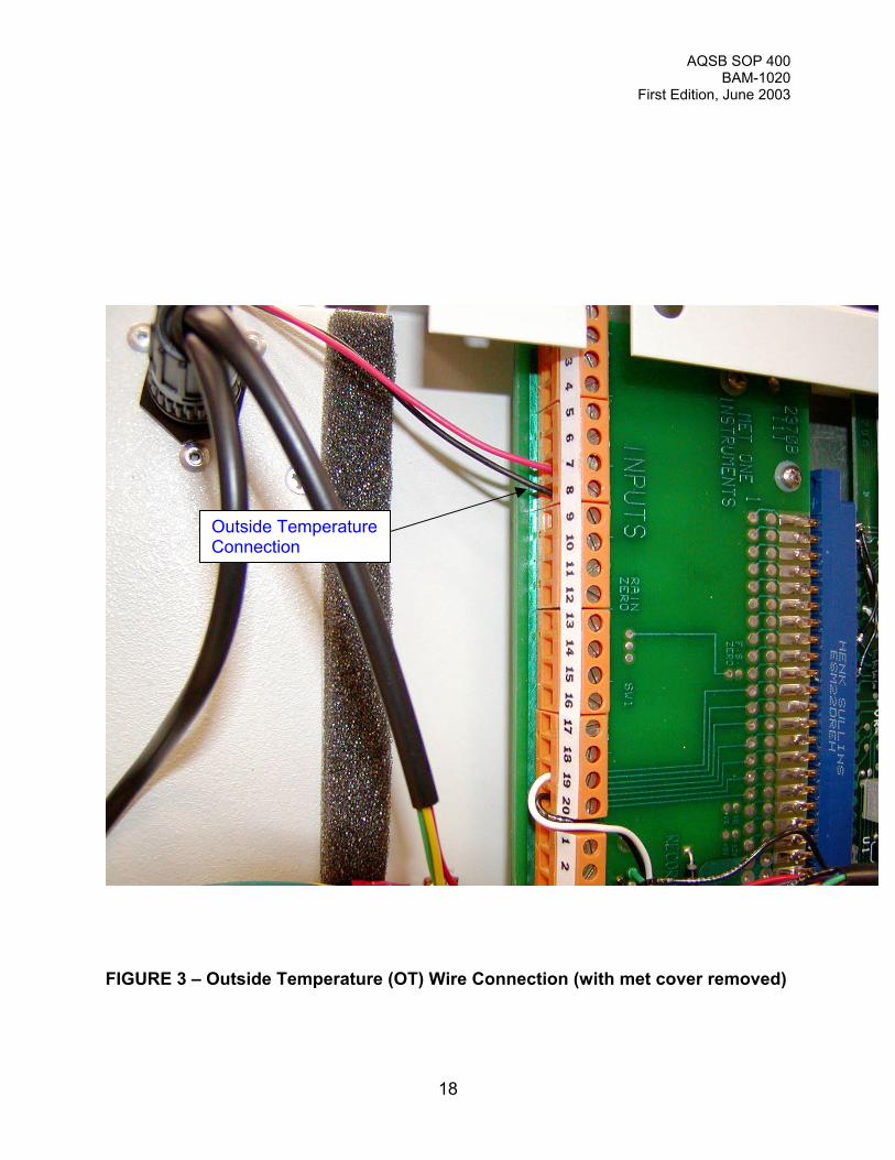
2.9 Outside Temperature (OT) Connection: Refer to Figure 3 (page 18).
All ARB deployed BAM-1020 monitors will be configured for volumetric flowcontrol. This will require the installation of either the supplied OT sensor or theexisting station OT sensor. The BAM-1020 OT out can be connected to eitherthe ESC 8800 or 8816 data logger. The BAM-1020 OT sensor must becalibrated prior to the BAM-1020 monitor flow calibration.
Connect the OT thermister cable wires to the orange input blocks on the BX-964translator located behind the tan plate on the back of the BAM. Attach the OTsensor leads to connectors 7 and 8 by the block labeled “INPUTS CH3”.
2.10 ESC 8800 / 8816 Data Logger Connection:
ESC 8800 data logger connection: When using an ESC 8800 data logger, twoseparate data logger channels are required; one channel for data collection andone channel for contact closure control.
A) Data channel connection: Refer to Figure 2 (page 17). Attach one end ofa shielded 2 wire cable (not supplied) to the (+) and (-) connectors at rearof the BAM-1020 labeled ‘VOLT OUT’. Attach the other end of the (+)lead to the ESC 8800 “Analog In” channel 6. Attach the other end of the (-) lead to the ESC 8800 ‘Analog In’ ‘GND’.
B) Contact closure channel connection: Refer to Figure 2(page 17). Acontact closure connection is required to sync the BAM-1020 clock withthe ESC 8800 data logger. The importance of syncing the two clockstogether is limited to the tight time frame in which BAM-1020 data isavailable and the necessity of the ESC data logger collected it before thesampling hour is ended.
AQSB SOP 400BAM-1020
First Edition, June 2003
16
Attach one end of a shielded 2-wire cable (not supplied) to the connectors at rearof the BAM monitor labeled ‘EXT RESET N.V.’. Attach the other end of the 2lead wire to the ESC 8800 channel 6 “Digital Out”.
ESC 8816 data logger connection: When using an ESC 8816 data logger, twoseparate data logger channels are also required, though the configurations arequite different than the ESC 8800 configuration. One channel is configured asthe raw BAM-1020 input and the other is configured for a math averagingfunction. The ESC 8816 contact closure commands are independent of channelconfigurations. A hard wire connection must be installed for the BAM-1020 rawdata and the clock contact closure function. No hard wiring is necessary for the'math averaging' channel.
A) Raw data channel connection: Attach one end of a shielded 2 wire cable(not-supplied) to the (+) and (-) connectors at rear of the BAM monitorlabeled ‘VOLT OUT’. Attach the other end of the (+) and (-) lead to theESC 8816 “Analog In” channel 32.
B) Contact closure channel connection: A contact closure connection isrequired to sync the BAM monitor clock with the ESC 8816 data logger. Again, the importance of syncing the two clocks together is limited to thetight time frame in which BAM-1020 data is available and the necessity ofthe ESC data logger collected it before the sampling hour is ended.
Attach one end of a shielded 2-wire cable (not supplied) to the connectors at rearof the BAM monitor labeled ‘EXT RESET N.V.’. Attach the other end of the 2-wire cable to the ESC 8816 channel 6 “Digital Out”.
AQSB SOP 400BAM-1020
First Edition, June 2003
17
FIGURE 2 – Data Logger / Pump Connection (rear view of BAM-1020)
Contact Closure
Pump Control
Data Output
AQSB SOP 400BAM-1020
First Edition, June 2003
18
FIGURE 3 – Outside Temperature (OT) Wire Connection (with met cover removed)
Outside TemperatureConnection

AQSB SOP 400BAM-1020
First Edition, June 2003
19
3.0 CONFIGURATION
3.1 Configure BAM-1020: Each BAM-1020 is calibrated at the factory and thereforehas unique calibration settings. The correct settings for BAM-1020 are located inAppendix B of the BAM-1020 Operation Manual.
As with any instrument, it is always important to exit out to the main menu andreturn back to check if the changes were in fact saved. If changes in theconfiguration have not been saved, the cause is often due to a configurationparameter that is out of the BAM-1020 operating range or a value that issignificantly different than the current operating conditions.
When configuring or calibrating the BAM-1020, it is important to exit out to themain menu before proceeding to the next parameter. This will ensure that eachchange has been saved and that the BAM-1020 has updated it’s memory to thenew configuration or set point. The BAM-1020 is in the main menu when thebottom of the display reads the words “SETUP”, “OPERATE”, “TEST” and“TAPE”.
Clock Set: When setting up the BAM-1020, it is crucial that the BAM-1020 clockis set to the ESC data logger clock (within 30 seconds). If the clocks are not setto within 30 seconds of each other, then the clock syncing program will not workand the data will be flagged. To set the clock:
1) Press the “SETUP” soft key.
2) Ensure that the cursor is in the word ‘CLOCK and press the “SELECT”soft key.
3) Use the cursor arrows to adjust the BAM-1020 date and time.
4) Press the “SAVE” soft key.
5) Press the “EXIT” soft key.
6) Confirm BAM-1020 date and time display in main menu.

AQSB SOP 400BAM-1020
First Edition, June 2003
20
Early Cycle Mode: There are two different configurations for the BAM-1020analog output; the ‘Standard’ mode and the ‘Early’ cycle mode. To configure theBAM-1020 so that either type of ESC data logger will capture BAM-1020 datawithin the correct hour, the BAM-1020 MUST be configured in the ‘Early’ cyclemode. To configure the BAM-1020 to “EARLY’ cycle mode:
1) Press the “SETUP” soft key.
2) Use the arrow keys to move the cursor to the word ‘INTERFACE’ andpress the “SELECT” soft key.
3) The word ‘EARLY’ should be displayed to the immediate right ‘CycleMode:’.
4) If the word ‘STANDARD” is displayed, press the up arrow key once. Theword ‘EARLY’ should appear.
5) Change ‘STANDARD’ to ‘CYCLE’ by pressing the down arrow key once.
6) Press the “SAVE” soft key.
7) Press the “EXIT” soft key.
8) Confirm ‘EARLY’ cycle mode configuration by performing steps 1 through3.
BAM-1020 'offset' voltage output configuration: All ARB BAM-1020 monitors areinitially configured with a negative offset of -0.005 VDC. This offset works incombination with the ESC data logger configurations listed in section 3.2 andonly affects the voltage output to the ESC data logger. With this negative offset,the data logger has the capacity of calculate and store negative values. Theability for the ESC data logger to collect negative values have proved essentialwhen trying to determine if a BAM-1020 monitor is working correctly.
To configure the BAM-1020 monitor with the correct offset:
1) Press the “SETUP” soft key.
2) Use the arrow keys to move the cursor over to the word ‘sample’ andpress the key under the word “SELECT”.
3) Using the side arrow keys, move the cursor down to the bottom right(offset). With the up and down arrow keys, change the offset value to -0.005.
4) Press the “SAVE” soft key.

AQSB SOP 400BAM-1020
First Edition, June 2003
21
5) Press the “EXIT” soft key.
6) Confirm offset configuration by performing steps 1 through 3.
Differences in ESC and BAM-1020 data logger values should consistently readno more than 1.0 ug/m3 from each other. After collecting several hourly datapoints, adjust Either the ESC or BAM-1020 offset voltage output so that the ESCdata is always equal to or 1.0 ug/m3 less than the BAM-1020 data set. Currently,the BAM-1020 data set expresses the hourly average of the ending time. Forexample, the averages logged by the BAM-1020 at 9:00 am were actuallycollected during the 8:00 hour. Data collected during the 8:00 am hour will belogged by the ESC data logger as 8:00 am data. The relationship between ESCand BAM-1020 data should be checked during each monthly data set review.
Volumetric flow mode configuration: Depending on the firmware version, thereare two or three different configurations for flow; 1) ‘METERED’ and‘VOLUMETRIC’ and 2) 'METERED', 'STD' and 'ACTUAL' (the calibrationprocess is different for each mode). For Federal Reference Method (FRM)PM2.5 filter comparability, all ARB deployed BAM-1020 monitors are configuredfor 'VOLUMETRIC’ or 'ACTUAL' flow control. To check the BAM-1020 for correct‘VOLUMETRIC’ or 'ACTUAL' flow control configuration:
1) Press the “SETUP” soft key.
2) Use the arrow keys to move the cursor over to the word ‘Calibrate’ andpress the “SELECT”.
3) The word ‘VOLUMETRIC’ or 'ACTUAL' should be displayed to theimmediate right of ‘FLOW TYPE’. If not, use the arrow keys to set correctflow type.
4) Press the “SAVE” soft key.
5) Press the “EXIT” soft key.
6) Confirm ‘VOLUMETRIC’ or 'ACTUAL' flow control configuration byperforming steps 1 through 3.

AQSB SOP 400BAM-1020
First Edition, June 2003
22
3.2 Configure ESC data logger:
ESC 8800 data logger configuration: Configuring the ESC 8800 to the BAM-1020 will require initializing two channels (channel 06 for data acquisition andchannel 32 for contact closure function).
ESC 8800 data channel (06) configuration: Channel 06 will be configured forBAM-1020 data acquisition for all ARB sites with Met One BAM Monitors. Theconfiguration used will be a one-hour tape sample mode that collects only thelast minute of data for each hour, using that minute of data to represent thehourly average for the same hour. The ESC 8800 program configuration is asfollows:
LIST 00CHANNEL NUMBER: 06CHANNEL NAME: BAM CHANNEL TYPE: DSTORE HOURLY AVERAGES: Y HOURLY SIGMAS: N HOURLY % VALID: N HOURLY RANGE: NSTORE AUX AVERAGES: NCHANNEL UNITS: UG/M3VOLTS FULL SCALE: 1.000SLOPE: 1000.INTERCEPT: -5.000DECIMAL POSITIONER: 0MAX READING: 9999.MIN READING: -999.0MAX RATE OF CHANGE: 5000.ALARM INTERVAL [N,M,A,H]: NBAD STATUS= XXXXXXXX XXXXXXXXCALIBRATION TYPE: N10-STEP CALIBRATION: NON-LINE: Y

AQSB SOP 400BAM-1020
First Edition, June 2003
23
ESC 8800 Contact closure configuration: Channel 32 has been selected on theESC 8800 as the TRIGR channel. The TRIGR channel configuration is asfollows:
LIST 32CHANNEL NUMBER: 32CHANNEL NAME: TRIGRCHANNEL TYPE: 9STORE HOURLY AVERAGES: NSTORE AUX AVERAGES: NCHANNEL UNITS: VOLTS FULL SCALE: 10.00SLOPE: .0000INTERCEPT: .0000DECIMAL POSITIONER: 0MAX READING: 9999.MIN READING: -999.0MAX RATE OF CHANGE: 5000.ALARM INTERVAL [N,M,A,H]: NBAD STATUS= XXXXXXXX XXXXXXXXCALIBRATION TYPE: AWEEKLY ALT CAL: NAUTO-CAL START TIME: 00:55ZERO LINES: 06,00,00 * (this set point designates digital output channel 06)ZERO DURATION TIME: 01ZERO RESPONSE TIME: 01SPAN1 LINES: 00,00,00SPAN1 DURATION TIME: 00SPAN1 RESPONSE TIME: 00SPAN2 LINES: 00,00,00SPAN2 DURATION TIME: 00SPAN2 RESPONSE TIME: 00RECOVERY TIME: 00CAL SEQUENCE: Z12EXPECTED SPAN1, SPAN2: .0000, .000010-STEP CALIBRATION: NON-LINE: Y
AQSB SOP 400BAM-1020
First Edition, June 2003
24
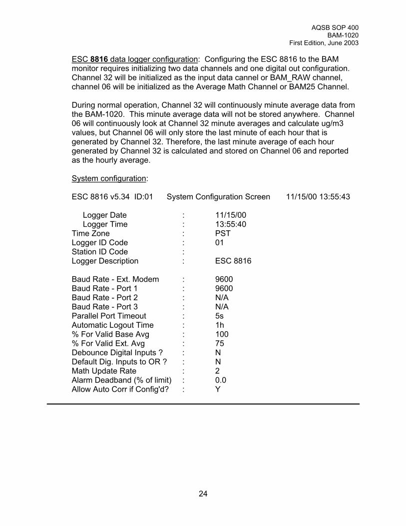
ESC 8816 data logger configuration: Configuring the ESC 8816 to the BAMmonitor requires initializing two data channels and one digital out configuration. Channel 32 will be initialized as the input data cannel or BAM_RAW channel,channel 06 will be initialized as the Average Math Channel or BAM25 Channel.
During normal operation, Channel 32 will continuously minute average data fromthe BAM-1020. This minute average data will not be stored anywhere. Channel06 will continuously look at Channel 32 minute averages and calculate ug/m3values, but Channel 06 will only store the last minute of each hour that isgenerated by Channel 32. Therefore, the last minute average of each hourgenerated by Channel 32 is calculated and stored on Channel 06 and reportedas the hourly average.
System configuration:
ESC 8816 v5.34 ID:01 System Configuration Screen 11/15/00 13:55:43
Logger Date : 11/15/00 Logger Time : 13:55:40Time Zone : PSTLogger ID Code : 01Station ID Code :Logger Description : ESC 8816
Baud Rate - Ext. Modem : 9600 Baud Rate - Port 1 : 9600 Baud Rate - Port 2 : N/A Baud Rate - Port 3 : N/A Parallel Port Timeout : 5s Automatic Logout Time : 1h % For Valid Base Avg : 100 % For Valid Ext. Avg : 75
Debounce Digital Inputs ? : NDefault Dig. Inputs to OR ? : NMath Update Rate : 2Alarm Deadband (% of limit) : 0.0Allow Auto Corr if Config'd? : Y

AQSB SOP 400BAM-1020
First Edition, June 2003
25
Standard Cannel Configuration:
ESC 8816 v5.34 ID:01 Standard Channel Config. 11/15/00 13:45:10
Instrument Name : BAM_RAWAnalog Input Number : 32Report Channel Number : 32Volts Full Scale : 1High Input : 1 VLow Input : 0 VHigh Output (E.U.s) : 995Low Output (E.U.s) : -5Units : UG/M3Base Avg. Interval, Storage : 1m , 1d 55mAverage #1 Interval, Storage : 15m , 0sAverage #2 Interval, Storage : 1h , 0sUse 40CFR75 Validation (Y/N) : NFINISHED (Configure Now) : 11/15/00 11:14:18
Average Validation Configuration:
To configure the following ‘Average Validation Configuration’ parameters, movethe cursor in the above menu to the ‘Base Avg. Interval, Storage : 1m , 1d 55m‘line and press ‘CTRL’ ‘V’ (the ‘CTRL’ function requires pressing both blue andorange keys simultaneously).
ESC 8816 v5.34 ID:01 Average Validation Config. 11/15/00 13:43:19
High-High Alarm Limit (H) : E+10High Alarm Limit (h) : 1E+10Low Alarm Limit (l) : -1E+10Low-Low Alarm Limit (L) : -1E+10High ROC Alarm Limit (J) : 1E+10Low ROC Alarm Limit (j) : 1E+10Floor Limit (f) : -1E+10Floor Value : 0Ceiling Limit (c) : 1E+10Ceiling Value : 0
Percent for valid average : Default (100)Average to Math Constant : K1

AQSB SOP 400BAM-1020
First Edition, June 2003
26
Configure Channel Options:
ESC 8816 v5.34 ID:01 Config. Channel Options 11/15/00 13:44:45
Name (not editable) : BAM_RAWChl Number (not editable) : 32Decimal Positioner : 00
Span for Cal Err : (not set)Round Precision : (none)
Average Math Channel Configuration:
ESC 8816 v5.34 ID:01 Average Math Channel Config. 11/15/00 13:47:43
Instrument Name : BAM25Report Channel Number : 06Equation : K1=Units : UG/M3Base Avg. Interval, Storage : 1m , 0sAverage #1 Interval, Storage : 15m , 0sAverage #2 Interval, Storage : 1h , 14d 9hRound Constituents: (Y/N) : NUse 40CFR75 OOC (Y/N) : NFINISHED (Configure Now) : 11/15/00 10:38:54
Instrument Validation Configuration:
ESC 8816 v5.34 ID:01 Inst. Validation Config. 11/15/00 13:48:54
Bad Status Lines (B) : (none)Maintenance Status Lines (M) : (none)Boiler Offline Status (F) : (none)Maximum Reading Limit (+) : 1E+10Minimum Reading Limit (-) : -1E+10Rate of Change Limit (R) : 1E+10Digital Info Status #1 (V) : (none)Digital Info Status #2 (W) : (none)Digital Info Status #3 (X) : (none)Digital Info Status #4 (Y) : (none)Digital Info Status #5 (Z) : (none)

AQSB SOP 400BAM-1020
First Edition, June 2003
27
Digital Event Program Configuration:
ESC 8816 v5.34 ID:01 Config. Dig. Event Program 11/15/00 13:51:26
Dig. Event Program Name : BAMStarting Time : 11/15/00 13:55:00Repeat Interval : 1hOutput Line(s) : 6, *(designates ch, digital out)Output Duration : 5sDisable During Cal(s) : (none)
AQSB SOP 400BAM-1020
First Edition, June 2003
28
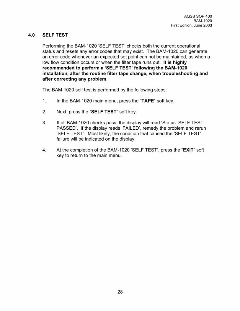
4.0 SELF TEST
Performing the BAM-1020 ‘SELF TEST’ checks both the current operationalstatus and resets any error codes that may exist. The BAM-1020 can generatean error code whenever an expected set point can not be maintained, as when alow flow condition occurs or when the filter tape runs out. It is highlyrecommended to perform a ‘SELF TEST’ following the BAM-1020installation, after the routine filter tape change, when troubleshooting andafter correcting any problem.
The BAM-1020 self test is performed by the following steps:
1. In the BAM-1020 main menu, press the “TAPE” soft key.
2. Next, press the “SELF TEST” soft key.
3. If all BAM-1020 checks pass, the display will read ‘Status: SELF TESTPASSED’. If the display reads ‘FAILED’, remedy the problem and rerun‘SELF TEST’. Most likely, the condition that caused the ‘SELF TEST’failure will be indicated on the display.
4. At the completion of the BAM-1020 ‘SELF TEST’, press the “EXIT” softkey to return to the main menu.

AQSB SOP 400BAM-1020
First Edition, June 2003
29
5.0 CALIBRATION INFORMATION
5.1 Calibration Introduction: The purpose of this section is to outline the Met OneBeta Attenuation Mass Monitor, model 1020 (BAM-1020) verification andcalibration procedures used by the AIR Quality Surveillance Branch of theCalifornia Air Resources Board (ARB). The Met One Instrument’s BAM-1020Operation Manual is an important resource of information for BAM-1020calibrations, and therefore ARB highly recommends a thorough review of theBAM-1020 Operation Manual.
5.2 Calibration Overview: The BAM-1020 requires the calibration of the outsidetemperature sensor (OT), the internal pressure sensor and the volumetric flowcontroller. Depending on the firmware version of the BAM-1020, there are eithertwo or three different flow configurations. Older firmware designate "METERED'or 'VOLUMETRIC' flow. Current firmware versions designate 'METERED', 'STD'or 'ACTUAL' flow. The 'METERED' configuration controls flow at standardconditions and calculates the hourly average mass value in terms of standardflow conditions, flow is not controlled using local temperature and pressureinformation. The 'STD' configuration controls flow using actual conditions(applying local temperature and pressure conditions) but will calculate the hourlyaveraged mass value at standard temperature and pressure conditions. 'VOLUMETRIC' and 'ACTUAL' flow will control and calculate flow using actual(local temperature and pressure) conditions. All BAM-1020 monitors purchasedby ARB will be configured in the 'VOLUMETRIC' or 'ACTUAL' flow mode (thusrequiring the installation of an OT sensor). When configuring or calibrating theBAM-1020, a password is required. The default password is F1 F2 F3 F4.
Met One BAM-1020 is calibrated using the following steps:
1. Leak Check2. BAM-1020 flow control check3. Outside temperature (OT) calibration/verification.4. Internal pressure calibration/verification.5. Volumetric flow calibration/verification.
Record all calibration information and data.
It is important to exit back to the main menu between each complete calibrationparameter. As with most software driven monitoring equipment, returning to themain menu between calibrations can be imperative when adjustments are madeto specific components that ultimately impact the calibration and/or operation ofthe instrument’s other components. Exiting out of the calibration screen andreturning to the main menu between calibrating each component allows theBAM-1020 to completely update any configurations or changes made. Temperature and pressure changes are especially critical with respect to theBAM-1020’s volumetric flow control.

AQSB SOP 400BAM-1020
First Edition, June 2003
30
Checking the BAM-1020 flow controller will help determine proper operation andaid as a troubleshooting technique. By changing the BAM-1020 16.7 volumetricliter per minute (VLPM) flow set point to a lower and a higher value, the operatorcan determine if the BAM-1020 flow controller is capable of re-adjusting andholding at the new flow value and therefore operating properly. Checking theBAM-1020 flow controller can be accomplished by accessing the "SETUP" menuand selecting the 'sample' screen. Change the 16.7 VLPM set point to a lowerflow rate (maybe around 13 VLPM) and select save. Exit and turn on the BAM-1020 flow by going through the "TEST" menu, selecting 'FLOW' and turning onthe pump. The 'BAM' flow should adjust to the new set point and hold steady. Go back and change the BAM-1020 flow set point higher than 16.7 VLPM(somewhere around 18 VLPM) and check. If the BAM-1020 adjusts and holds atboth flow set points, then the BAM-1020 flow controller is most likely operatingproperly. If the BAM-1020 flow does not adjust to one or both flow set points,then a problem is present and requires immediate correction. If the BAM-1020can adjust and hold at a flow lower than 16.7 VLPM but not at a flow higher 16.7VLPM, then a leak between the pump and flow meter or a tired pump could bethe cause. If the BAM-1020 'BAM' flow does not adjust downward to a set pointlower than 16.7 VLPM, then a bad flow controller is most likely the culprit.
5.3 Apparatus for BAM-1020 Calibration
1. NIST-traceable mass flow transfer standard*2. NIST-traceable temperature meter3. NIST-traceable pressure meter4. Tubing5. Calibration forms or laptop computer
*Note: Other flow measuring devices may be substituted, such as the R&P FTSStreamline Calibration Kit or BGI Delta/Tri Cal.

AQSB SOP 400BAM-1020
First Edition, June 2003
31
6.0 CALIBRATION PROCEDURE
6.1 Calibration Transfer Standards and Equipment: All calibration transfer standardequipment must possess up-to-date certification. Certified temperature andpressure sensors are required for both BAM-1020 outside temperature andpressure calibrations. A certified mass flow meter or certified fixed orifice device(such as the FTS Streamline) will be required for flow calibrations.
Allow all AC powered equipment to equilibrate to ambient conditions for aminimum of one (1) hour.
6.2 Temperature Sensor Calibration (OT): The BAM-1020 external OT sensor iscalibrated by initiating the BAM-1020 temperature calibration sequence andentering a single ambient temperature value. Perform the following steps tocalibrate the BAM-1020 OT sensor:
1. In the BAM-1020 main menu, press the “TEST” soft key.
2. Using the right arrow key, move the cursor over to the word ‘FLOW’ andpress the “SELECT” soft key.
3. With the arrow keys, enter the corrected ambient temperature (in 0C fromthe certified temperature standard), on the row to the right of ‘AMBIENTTEMPERATURE’, under the column labeled ‘REFERENCE’.
4. Press the “ADJUST/SAVE” soft key.
5. Press the “EXIT” soft key.
6. Confirm OT calibration by performing steps 1 through 3.
6.3 Barometric Pressure Sensor Calibration:
The BAM-1020 internal barometric pressure sensor is calibrated by initiating theBAM-1020 barometric sensor calibration sequence and entering a single ambientpressure value. Perform the following steps to calibrate the BAM-1020barometric pressure sensor:
1) Press the “TEST” soft key from the main menu.
2) Using the right arrow key, move the cursor over to the word ‘FLOW’ andpress the “SELECT” soft key.
3) Press the “NEXT” soft key.

AQSB SOP 400BAM-1020
First Edition, June 2003
32
4) With the arrow keys, enter the corrected ambient pressure (in mmHg) onthe row to the right of ‘BAROMETRIC PRESSURE’, under the columnlabeled ‘REFERENCE’.
5) Press the “ADJUST/SAVE” soft key.
6) Press the “EXIT” soft key.
7) Confirm the internal pressure calibration by performing steps 1 through 3.
6.4 Volumetric Flow Rate Calibration
The BAM-1020 volumetric flow controller is calibrated by initiating the BAM-1020volumetric flow calibration sequence and entering a single through-the-inletvolumetric flow value. To acquire the correct volumetric flow value, remove thePM10 inlet and measure the standard mass flow of the BAM-1020 (leave thePM2.5 SCC inlet attached to the inlet tube if sampling PM2.5). Convert themeasured standard flow to volumetric flow using a certified transfer standardambient temperature and pressure values. Enter the calculated volumetric flowinto the BAM-1020 by:
1) Press the “TEST” soft key.
2) Using the right arrow key, move the cursor over to the word ‘FLOW’ andpress the “SELECT” soft key.
3) Press the “PUMP ON” soft key and allow pump to run for several minutes(the cursor will automatically move to the ‘VOLUMETRIC FLOWRATE’row under the column labeled ‘REFERENCE’. The value in the‘VOLUMETRIC FLOWRATE’ row under the ‘BAM’ column must read16.7.
4) At the inlet on the rooftop, remove the PM10 inlet and measure thestandard flow rate through the inlet tube (leave the PM2.5 inlet on ifpresent).
5) Calculate the volumetric flow rate. The equation to convert standard flowrate to volumetric flow is:
Volumetric flow = ( std. flow* )( 760 mm Hg )( ambient temp in K ) ( ambient pressure in mm Hg )( 298 K )
*Note: std. mass flow meter values are calculated by:
std. flow = [(MFM disp)(MFM cert. slope)] + (MFM cert. intercept)

AQSB SOP 400BAM-1020
First Edition, June 2003
33
6) With the arrow keys, enter in the calculated volumetric flow rate.
7) Press the “ADJUST/SAVE” soft key.
8) Press the “EXIT” soft key (pressing the “EXIT” soft key will automaticallyturn off the pump).
9) Verify the correct flow rate by repeating steps 1 through 3. The calculatedvolumetric flow must be within +/- 2% of 16.67 L/min (16.34 to 17.00LPM). The equation for calculating the percent difference is:
% diff. = (Volumetric flow - 16.67) x 100% 16.67
AQSB SOP 400BAM-1020
First Edition, June 2003
34
7.0 BAM-1020 VERIFICATION PROCEDURES
7.1 Flow Rate Verification: The flow rate can be verified using one of twoprocedures. One flow verification procedure can be performed while the BAM-1020 is in ‘normal’ operating mode. The other flow verification procedure can beperformed by keying into the BAM-1020 flow calibration screen and turning onthe pump. The preferred method for biweekly flow checks or biannual calibrationis while the BAM-1020 is running in the ‘normal’ operating mode. When verifyingflow after a BAM-1020 flow calibration, it will be more efficient to verify flow usingthe calibration mode procedure (this is because it may take up to two (2) hoursfor the BAM-1020 to start operating after it is placed in ‘normal’ operating mode). Perform either flow rate verification procedure by removing only the FRM PM10impactor and measuring the flow through the inlet tube (leave on the PM2.5sharp cut cyclone if configured). To meet flow verification criteria, the calculatedvolumetric flow must be within 4% of 16.67 VLPM (16.00 to 17.34 VLPM).
Verifying flow in ‘normal’ operating mode: To verify the flow in ‘normal’ operatingmode, simply remove the FRM PM10 impactor and measure the flow. The BAM-1020 pump only operates for fifty (50) minutes of each hour. Verify that thepump is running when the checking flow in the ‘normal’ operating mode.
Verifying flow in flow calibration mode: Verify BAM-1020 flow rate only throughthe “TEST” screen. Be sure NOT to press the “ADJUST/SAVE” soft key duringthis procedure. To verify the BAM-1020 the flow calibration:
1) Press the “TEST” soft key.
2) Using the right arrow key, move the cursor over to the word ‘FLOW’ andpress the “SELECT” soft key.
3) Press the “PUMP ON” soft key and allow pump to run for several minutes(the cursor will automatically move to the ‘VOLUMETRIC FLOWRATE’row under the column labeled ‘REFERENCE’. The value in the‘VOLUMETRIC FLOWRATE’ row under the ‘BAM’ column must read16.7.
4) At the inlet on the rooftop, remove the PM10 inlet and measure thestandard flow rate through the inlet tube (leave the PM2.5 inlet on ifpresent).
AQSB SOP 400BAM-1020
First Edition, June 2003
35
5) Calculate the volumetric flow rate. The equation to convert standard flowrate to volumetric flow is:
Volumetric flow = (std. flow)(760 mm Hg)( ambient temp in K)(ambient pressure in mm Hg)(298 K)
6) Verify the correct flow rate by repeating steps 1 through 3. The calculatedvolumetric flow must be within +/- 2% of 16.7 L/min. The equation forcalculating the percent difference is:
% diff. = (Volumetric flow - 16.7) x 100%16.7
7) Press the “EXIT” soft key (pressing the “EXIT” soft key will automaticallyturn off the pump).
7.2 Temperature Sensor Verification: To verify the BAM-1020 external OT sensor:
1) Press the “TEST” soft key.
2) Using the right arrow key, move the cursor over to the word ‘FLOW’ andpress the “SELECT” soft key.
3) Compare the BAM-1020 temperature value listed on the row to the right of‘AMBIENT TEMPERATURE’, under the column labeled ‘BAM’ to thecorrected ambient temperature standard value.
4) Record and calculate the percent difference from the corrected ambientcertified temperature transfer standard value.
5) Remain in this screen for ambient pressure verification or press the “EXIT”soft key.
7.3 Barometric Pressure Verification: To verify the BAM-1020 external OT sensor:
1) Press the “TEST” soft key.
2) Using the right arrow key, move the cursor over to the word ‘FLOW’ andpress the “SELECT” soft key.
3) Compare the BAM-1020 internal barometric pressure value listed on therow to the right of ‘BAROMETRIC PRESSURE’, under the column labeled‘BAM’ to the corrected ambient pressure standard value.

AQSB SOP 400BAM-1020
First Edition, June 2003
36
4) Record and calculate the percent difference from the corrected ambientcertified pressure transfer standard value.
5) Press the “EXIT” soft key.
7.4 Clock/Timer Verification: Compare the date and time of the BAM-1020 clockdisplay to the ESC data logger date and time display. If either the date or time ofthe BAM-1020 does not agree with the ESC data logger, correct the BAM-1020to match the ESC data logger. The BAM-1020 clock should be set to as close tothe ESC data logger as possible (within thirty (30) seconds). If the BAM-1020clock drifts significantly from the ESC data logger, then the data will becomeflagged. Clock drift indicates that a problem may exist with the contact closurerelay configuration. Diagnose and correct.
All clocks are set to Pacific Standard Time (PST).

AQSB SOP 400BAM-1020
First Edition, June 2003
37
8.0 START SAMPLING
To start sampling:
From the main menu, press the “OPERATE” soft key.
Press the “NORMAL” soft key. In most cases, the BAM-1020 will typically startsampling at the beginning of the next hour if the BAM-1020 is configured to startno later than six (6) to ten (10) minutes before the beginning of the next hour. Tape movement will occur approximately five (5) minutes before the beginning ofthe next collection cycle (for tape zero reading). The BAM-1020 pump will turnon at the beginning of the hour and run for fifty (50) minutes.

AQSB SOP 400BAM-1020
First Edition, June 2003
38
9.0 LEAK CHECK
The BAM-1020 requires a leak check after installation and on a bi-weekly basisto ensure proper operation and data quality. The installation leak check shouldbe performed prior to temperature, pressure and flow calibration. The biweeklyleak check should be performed after the biweekly flow check. Leak checkinformation should be recorded on the BAM-1020 monthly quality controlmaintenance check sheet (Appendix A).
To perform a leak check, remove the FRM PM10 inlet from the BAM-1020 inletsystem. Cap off the flow at the inlet of the PM2.5 SCC. Capping off the inlet flowcan be achieved by using a PM2.5 FRM adaptor with stopcock or a rubberstopper. The flow display on the BAM-1020 must read less than 1.0 LPM withthe inlet capped off to pass the manufacturers recommended leak checkspecifications. The leak check flow value on the display screen of the BAM-1020should stabilize in less than 20 seconds to within two to three tenths of a liter perminute (0.2 – 0.3 lpm). Ensure that the leak check flow value remains stable fora minimum of fifteen (15) to twenty (20) seconds. It is recommended NOT toleave the BAM-1020 capped off in the leak check mode for any period of timelonger than necessary.
A leak check value between 0.7 and 1.0 LPM still passes but indicates thepotential of a leak check failure in the near future.
Note: Perform the BAM-1020 “SELF TEST’ before returning to normal samplingoperation. Performing a leak check will generate an error code in the BAM-1020due to the insufficient flow through the inlet. Performing a ‘SELF TEST’ will resetthe BAM-1020. The ‘SELF TEST’ procedure is described above in section 4.0 ofthis document.
AQSB SOP 400BAM-1020
First Edition, June 2003
39
10.0 ROUTINE SERVICE CHECKS
10.1 General Information: Perform the following checks on the BAM-1020 at theintervals specified in the service schedule. The checks may be performed morefrequently but should be performed at least within the prescribed intervals. Document all check information and maintenance on the Monthly Quality ControlMaintenance Check Sheet (Appendix A).
10.2 Daily Check: Review station datalogger values for correct operation of the BAM-1020.
10.3 Weekly Checks: Check the BAM-1020 filter tape and replace when necessary. One roll of filter tape is 22 meters long and will last for a minimum of 60 days.
10.4 Bi-weekly Checks:
1) Flow check: Perform an inlet flow verification to ensure a flow rate of16.67 VLPM (+/- 4 percent). Remove only the PM10 inlet whenmeasuring flow.
2) Leak check: Perform a Leak check. A BAM-1020 display of less than 1.0LPM passes the manufacturers leak check specifications.
The bi-weekly flow check can be performed while the BAM-1020 is in normaloperating mode. Remove only the FRM PM10 inlet from the BAM-1020 inletsystem. Affix either a mass flow measuring or volumetric flow measuring deviceonto the PM2.5 SCC inlet and record the volumetric flow on the monthly qualitycontrol maintenance check sheet.
10.5 Monthly Checks:
1) Complete and submit the BAM-1020 Monthly Quality Control MaintenanceCheck Sheet (Appendix A).
2) Thoroughly clean both the PM2.5 Sharp Cut Cyclone (SCC) and the PM10FRM inlets.
3) Download and submit BAM-1020 data logger data with charts andmaintenance sheets.
10.6 Semi-Annual Checks: Perform semi-annual BAM-1020 verification/calibration ofthe external ambient temperature, internal pressure, leak check and volumetricflow.
AQSB SOP 400BAM-1020
First Edition, June 2003
40
11.0 MAINTENANCE PROCEDURES
11.0 General Information: Normal BAM-1020 maintenance requires keeping theBAM-1020 central unit dust free and inlet cleaning.
11.1 Sampler Maintenance: As with all monitoring equipment, the BAM-1020 shouldbe kept clean and dust free.
11.2 PM2.5 Sharp Cut Cyclone (SCC) Maintenance: The PM2.5 SCC inlet requiresremoval from the inlet tube, disassembly and cleaning. The inlet should bethoroughly cleaned every month. Disassemble the SCC and wipe clean with lintfree cloth. Ensure that all ‘O’ ring surfaces are in excellent shape and are re-installed correctly. Replace 'O' rings when needed.
11.3 PM10 Inlet Maintenance: The PM10 inlet requires removal from the inlet tube,disassembly and cleaning. The inlet should be thoroughly cleaned every month. Disassemble the PM10 inlet and wipe clean with lint free cloth. Ensure that all‘O’ ring surfaces are in excellent shape and are re-installed correctly. Replace'O' rings when needed.
AQSB SOP 400BAM-1020
First Edition, June 2003
41
12.0 TROUBLESHOOTING and RETRIEVING BAM-1020 INTERNAL DATA
A desktop or laptop computer is an important tool when verifying proper datalogger acquisition and troubleshooting. Error codes, current BAM-1020configurations and BAM-1020 data can be observed and downloaded using theMicrosoft Windows HyperTerminal software program. The HyperTerminalProperties and Advanced Port Settings are:
1. Properties Screen:
Bits per second: 9600Data bits: 8Parity: NoneStop bits: 1Flow control: None
2. Advanced Port Settings Screen: Remove check from “Use FIFO buffers”.
Connect the computer port cable to the upper RS232 connector located at therear of the BAM-1020. Activate the HyperTerminal program and press thecomputer’s return button a couple times. An asterisk (*) should appear. If not,depress the small white and red polarity toggle switch located next to the RS232connector on the back of the BAM-1020. Type the letter H and a menu willappear. To download BAM-1020 data to a laptop or desk computer, the ‘CaptureText’ function of HyperTerminal can be used.
Should the BAM-1020 fail to operate, refer to section 10.3 of the BAM-1020operating manual. This section contains a troubleshooting guide that outlinessymptoms, checkpoints, probable cause and remedies for general problems.
BAM-1020 download data: BAM-1020 data shall be downloaded from themonitor and compared to ARB's AQDAS EMC data (remembering that the BAM-1020 data will stagger the EMC data by one hour).
Negative data: All valid BAM-1020 EMC negative hourly values shall becorrected to zero (as with all of ARB's continuous monitoring programs). Repeating values or an abundance of -5 ug/m3 values should be suspect tomonitor malfunction. If these either case appears, check for proper operation ofmonitor or for background drift using an appropriate zero air filter.
Daily Data Patterns: BAM-1020 data should express somewhat routinecharacteristics for each specific site. 'Flat' or erratic hour to hour mass valuesmay be the result of an operational malfunction. Changes in weather such asrain or seasons should influence 'normal' daily values.
AQSB SOP 400BAM-1020
First Edition, June 2003
42
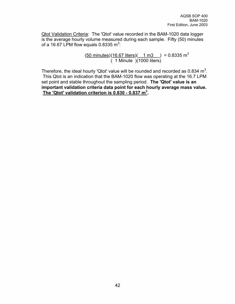
Qtot Validation Criteria: The 'Qtot' value recorded in the BAM-1020 data loggeris the average hourly volume measured during each sample. Fifty (50) minutesof a 16.67 LPM flow equals 0.8335 m3:
(50 minutes)(16.67 liters)( 1 m3 ) = 0.8335 m3
( 1 Minute )(1000 liters)
Therefore, the ideal hourly 'Qtot' value will be rounded and recorded as 0.834 m3. This Qtot is an indication that the BAM-1020 flow was operating at the 16.7 LPMset point and stable throughout the sampling period. The 'Qtot' value is animportant validation criteria data point for each hourly average mass value. The 'Qtot' validation criterion is 0.830 - 0.837 m3.

AQSB SOP 400BAM-1020
First Edition, May 2003
AQSB QC Form 400 (BAM)
CARB MONTHLY QUALITY CONTROL MAINTENANCE CHECK SHEETBAM-1020 SAMPLER
Site Name:Site Number:
Operator/Agency:
Month/Year:Sampler Make & Model:Sampler ID Number:Date of Last Calibration:
Instrument Checks:
1) Daily checks: Review station data logger values for correct operation of BAM-1020.2) Weekly checks: Check filter tape & replace when necessary (approx. 2 months per roll).3) Bi-Weekly checks: Perform BAM-1020 flow and leak.4) Monthly checks: Complete and submit this Monthly Quality Control Check Sheet.
Thoroughly clean both PM2.5 SCC and PM10 FRM inlets.Check pump muffler and replace when needed.Download and submit data from BAM-1020 data logger.
Sampler Flow Rate, Ambient Temp and Pressure Check Results:
Flow Rate Standard Temperature Standard Pressure Standard
Standard Make/Model:
Std. ARB ID Number:
Std. Certification Date:
Standard Slope:
Standard Intercept:
Date Checked:
Std. Display Reading:
Std. 'Actual' Reading:
BAM-1020 Display:
Design Flow % Diff.:
Leak Check Value:Volumetric Flow Acceptance Criteria: <+/-4% of 16.67 LPM (16.00 to 17.34 VLPM)
Operator Comments:
Reviewed by__________
Appendix A
AQSB SOP 400BAM-1020
First Edition, May 2003
AQSB Calibration Form 400 (BAM)
Appendix B
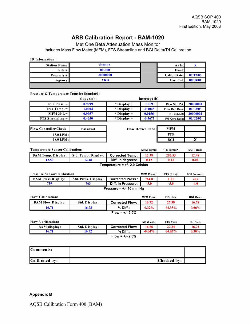
ARB Calibration Report - BAM-1020Met One Beta Attenuation Mass Monitor
Includes Mass Flow Meter (MFM), FTS Streamline and BGI Delta/Tri Calibration
ID Information:
Station Name: Station As Is: XSite #: 00-000 Final:
Property #: 20000000 Calib. Date: 02/17/03Agency: ARB Last Cal: 08/08/01
Pressure & Temperature Transfer Standard:slope (m) : Intercept (b):
True Press. = 0.9999 * Display + 1.059 Flow Std. ID#: 20000001True Temp. = 1.0004 * Display + -0.1045 Flow Cert.Date: 01/02/03
MFM 30 L = 0.9957 * Display + 0.0156 P/T Std.ID#: 20000002FTS Streamline = 0.4050 * Display + -0.5673 P/T Cert. Date: 01/02/03
Flow Controller Check Pass/Fail Flow Device Used: MFM
13.0 LPM: FTS18.0 LPM: BGI X
Temperature Sensor Calibration: MFM Temp: FTS Temp K: BGI Temp:
BAM Temp. Display: Std. Temp. Display: Corrected Temp: 12.38 285.53 12.4812.50 12.48 Diff. In degrees: 0.12 0.12 0.02
Temperature = +/- 2.0 Celsius
Pressure Sensor Calibration: MFM Press.: FTS (Atm): BGI Pressure:
BAM Press.Display: Std. Press. Display: Corrected Press.: 764.0 1.01 763759 763 Diff. In Pressure: -5.0 -5.0 -4.0
Pressure = +/- 10 mm Hg
Flow Calibration: MFM Flow: FTS Flow: BGI Flow:
BAM Flow Display: Std. Display: Corrected Flow: 16.72 27.39 16.7816.71 16.78 % Diff.: 0.32% 64.33% 0.66%
Flow = +/- 2.0%
Flow Verification: MFM Ver.: FTS Ver.: BGI Ver.:
BAM display: Std. Display: Corrected Flow: 16.66 27.34 16.7216.71 16.72 % Diff.: -0.04% 64.03% 0.30%
Flow = +/- 2.0%
Comments:
Calibrated by: Checked by:
AQSB SOP 400BAM-1020
First Edition, May 2003
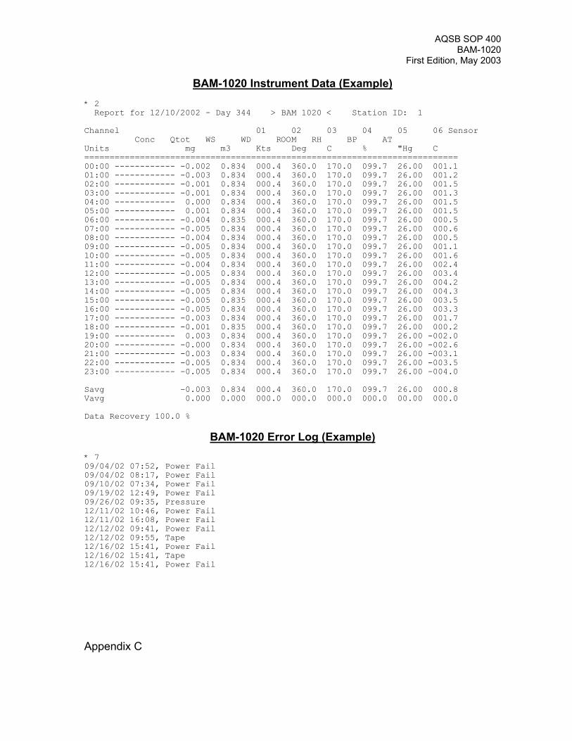
BAM-1020 Instrument Data (Example)* 2 Report for 12/10/2002 - Day 344 > BAM 1020 < Station ID: 1
Channel 01 02 03 04 05 06 Sensor Conc Qtot WS WD ROOM RH BP ATUnits mg m3 Kts Deg C % "Hg C ==========================================================================00:00 ------------ -0.002 0.834 000.4 360.0 170.0 099.7 26.00 001.101:00 ------------ -0.003 0.834 000.4 360.0 170.0 099.7 26.00 001.202:00 ------------ -0.001 0.834 000.4 360.0 170.0 099.7 26.00 001.503:00 ------------ -0.001 0.834 000.4 360.0 170.0 099.7 26.00 001.304:00 ------------ 0.000 0.834 000.4 360.0 170.0 099.7 26.00 001.505:00 ------------ 0.001 0.834 000.4 360.0 170.0 099.7 26.00 001.506:00 ------------ -0.004 0.835 000.4 360.0 170.0 099.7 26.00 000.507:00 ------------ -0.005 0.834 000.4 360.0 170.0 099.7 26.00 000.608:00 ------------ -0.004 0.834 000.4 360.0 170.0 099.7 26.00 000.509:00 ------------ -0.005 0.834 000.4 360.0 170.0 099.7 26.00 001.110:00 ------------ -0.005 0.834 000.4 360.0 170.0 099.7 26.00 001.611:00 ------------ -0.004 0.834 000.4 360.0 170.0 099.7 26.00 002.412:00 ------------ -0.005 0.834 000.4 360.0 170.0 099.7 26.00 003.413:00 ------------ -0.005 0.834 000.4 360.0 170.0 099.7 26.00 004.214:00 ------------ -0.005 0.834 000.4 360.0 170.0 099.7 26.00 004.315:00 ------------ -0.005 0.835 000.4 360.0 170.0 099.7 26.00 003.516:00 ------------ -0.005 0.834 000.4 360.0 170.0 099.7 26.00 003.317:00 ------------ -0.003 0.834 000.4 360.0 170.0 099.7 26.00 001.718:00 ------------ -0.001 0.835 000.4 360.0 170.0 099.7 26.00 000.219:00 ------------ 0.003 0.834 000.4 360.0 170.0 099.7 26.00 -002.020:00 ------------ -0.000 0.834 000.4 360.0 170.0 099.7 26.00 -002.621:00 ------------ -0.003 0.834 000.4 360.0 170.0 099.7 26.00 -003.122:00 ------------ -0.005 0.834 000.4 360.0 170.0 099.7 26.00 -003.523:00 ------------ -0.005 0.834 000.4 360.0 170.0 099.7 26.00 -004.0
Savg -0.003 0.834 000.4 360.0 170.0 099.7 26.00 000.8Vavg 0.000 0.000 000.0 000.0 000.0 000.0 00.00 000.0
Data Recovery 100.0 %
BAM-1020 Error Log (Example)* 709/04/02 07:52, Power Fail09/04/02 08:17, Power Fail09/10/02 07:34, Power Fail09/19/02 12:49, Power Fail09/26/02 09:35, Pressure12/11/02 10:46, Power Fail12/11/02 16:08, Power Fail12/12/02 09:41, Power Fail12/12/02 09:55, Tape12/16/02 15:41, Power Fail12/16/02 15:41, Tape12/16/02 15:41, Power Fail
Appendix C
AQSB SOP 400BAM-1020
First Edition, May 2003
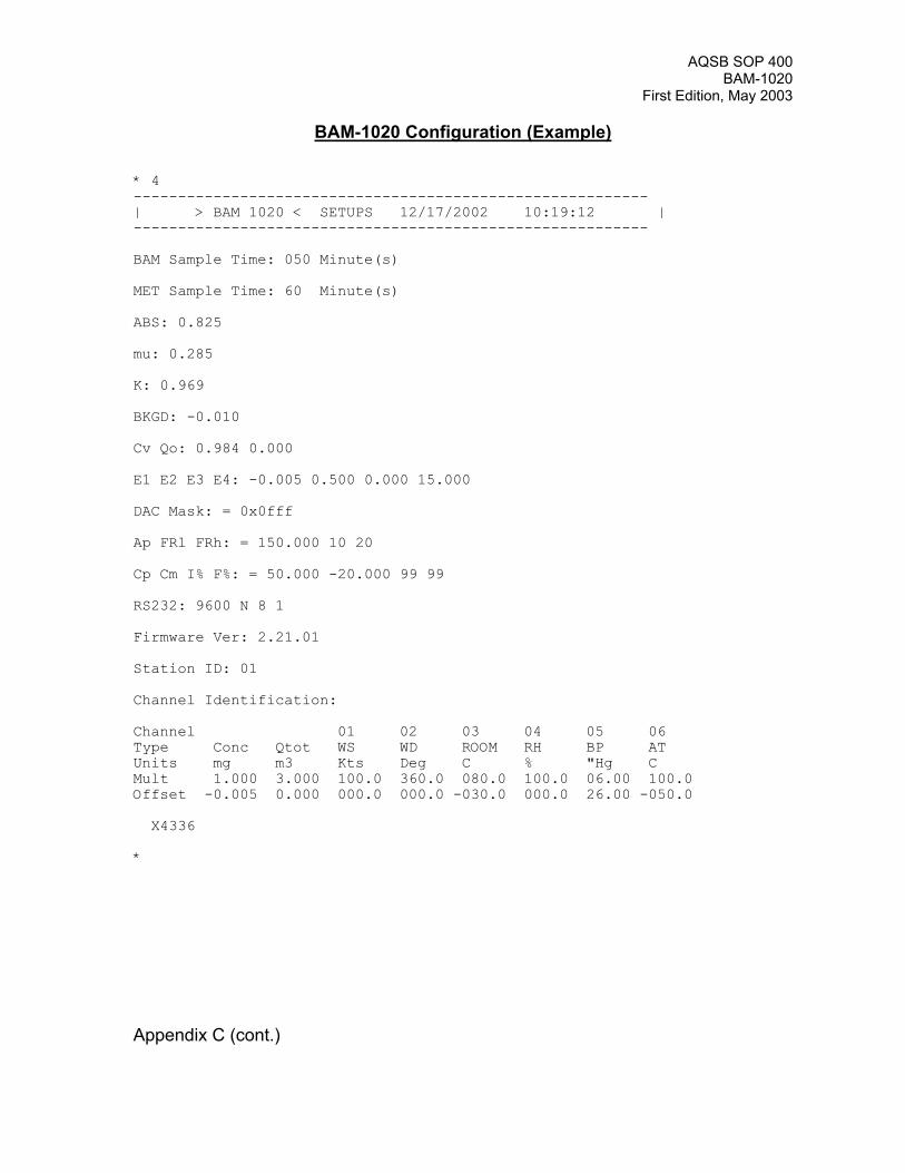
BAM-1020 Configuration (Example)
* 4----------------------------------------------------------| > BAM 1020 < SETUPS 12/17/2002 10:19:12 |----------------------------------------------------------
BAM Sample Time: 050 Minute(s)
MET Sample Time: 60 Minute(s)
ABS: 0.825
mu: 0.285
K: 0.969
BKGD: -0.010
Cv Qo: 0.984 0.000
E1 E2 E3 E4: -0.005 0.500 0.000 15.000
DAC Mask: = 0x0fff
Ap FRl FRh: = 150.000 10 20
Cp Cm I% F%: = 50.000 -20.000 99 99
RS232: 9600 N 8 1
Firmware Ver: 2.21.01
Station ID: 01
Channel Identification:
Channel 01 02 03 04 05 06 Type Conc Qtot WS WD ROOM RH BP AT Units mg m3 Kts Deg C % "Hg C Mult 1.000 3.000 100.0 360.0 080.0 100.0 06.00 100.0Offset -0.005 0.000 000.0 000.0 -030.0 000.0 26.00 -050.0
X4336
*
Appendix C (cont.)