aptica plus_eng_2003.pdf
DESCRIPTION
service manualTRANSCRIPT
apticaPLUS
© dental X 2003
OPERATING MANUAL
CLASS-B WATER STEAM STERILIZER
Rev. 1 Date: September 2003
0 1 2 0

Dental X
apticaPLUS 1
ENG
LISH
This sterilizer fulfills all the directions in force concerning the safety, and the built-in parameters has been properly set by the manufacturer in order to warranty effective sterilization if proper loading conditions are followed.
Please, read carefully this manual before using the machine; an improper utilization of the sterilizer should carry on defective sterilization with unattended consequences.
In case of doubt or questions, please call the agent.
Thanks for the confidence given.
All rights reserved
No portion of this publication can be printed, transmitted, rewritten, stored in a data recovery system, translated in any foreign or computer language, in any form or through any devices, without written consent by Dental X.
Information in this manual is subject to change without any warning or prior notice and does not represent a commitment for the vendor.
apticaPLUS is trademark of Dental X.
STERILINE is trademark of Dental X.
DENTAL X s.r.l. Via Marzotto 11 36031 Dueville (VI) Italy Tel. +39 444 367400 Fax +39 444 367436 e-mail: [email protected] http://www.dentalx.it
SERVICE Italy - Tel. +39 444 367415 Foreign country - Tel. +39 2 76275234
apticaPLUS
Operating Manual

Dental X
2 apticaPLUS
ENG
LISH
TABLE OF CONTENTS
1. GENERAL.......................................................................................................................3 1.1 FOREWORDS ..................................................................................................................................... 3 1.2 CONFORMITY TO EUROPEAN DIRECTIVES ................................................................................... 3
2. FAMILIARIZATION.........................................................................................................4 2.1 PACKAGE DIMENSIONS AND WEIGHT ............................................................................................ 4 2.2 PHYSICAL CHARACTERISTICS......................................................................................................... 4 2.3 CHAMBER DIMENSIONS AND CAPACITY ........................................................................................ 4 2.4 SAFETY FEATURES........................................................................................................................... 5 2.5 DEVICES OF THE STERILIZER ......................................................................................................... 6 2.6 STANDARD ACCESSORIES .............................................................................................................. 7 2.7 TECHNICAL SPECIFICATIONS.......................................................................................................... 7
2.7.1 Environment operating condition............................................................................................ 7 3. INSTALLATION ..............................................................................................................8
3.1 BASIC REQUIREMENTS .................................................................................................................... 8 3.2 PRELIMINARY STEPS........................................................................................................................ 9 3.3 NOTES ABOUT THE ALTITUDE COMPENSATION......................................................................... 10
4. OPERATION .................................................................................................................11 4.1 CONTROL PANEL............................................................................................................................. 11 4.2 CYCLE SEQUENCE .......................................................................................................................... 12
4.2.1 Program Selection................................................................................................................ 13 4.2.2 Running the cycle................................................................................................................. 14
4.3 STOPPING THE CYCLE IN ADVANCE............................................................................................. 16 4.4 TOPPING UP THE MAIN TANK - DRAINING THE USED WATER TANK ........................................ 16
4.4.1 Topping up the main tank..................................................................................................... 16 4.4.2 Draining the recovery tank ................................................................................................... 17
4.5 SOUND WARNING SIGNALS ........................................................................................................... 17 5. PROGRAMMING ..........................................................................................................18
5.1 SETTING DATE AND TIME............................................................................................................... 18 5.2 SETTING MEASUREMENT UNIT AND OPTIONS............................................................................ 18 5.3 SETTING THE SPECIAL CYCLE S4................................................................................................. 19
6. MAINTENANCE............................................................................................................20 6.1 PERIODIC CLEANING CYCLE.......................................................................................................... 20 6.2 CLEAN THE INSTRUMENT BEFORE STERILIZING........................................................................ 21 6.3 H2O FILTER MAINTENANCE / REPLACEMENT ............................................................................. 22 6.4 REGULAR STERILITY CHECKS....................................................................................................... 23
6.4.1 Bowie & Dick Test ................................................................................................................ 23 6.4.2 Vacuum Test........................................................................................................................ 23
7. AUTOTEST ...................................................................................................................24 7.1 MANUAL DIAGNOSIS ....................................................................................................................... 24 7.2 AUTOMATIC TROUBLESHOOTING AT THE SWITCHING-ON ....................................................... 25
7.2.1 Water quality control ............................................................................................................ 25 8. ALARMS.......................................................................................................................26
8.1 GENERAL.......................................................................................................................................... 26 8.2 WARNING MESSAGES..................................................................................................................... 26 8.3 PRE-WARNING ALARMS ................................................................................................................. 27 8.4 ABORTED CYCLE ALARMS ............................................................................................................. 28 8.5 CLASS B ADDITIONAL ALARMS...................................................................................................... 28
9. CONNECTIONS............................................................................................................29 9.1 PRINTER CONNECTION .................................................................................................................. 29 9.2 PC CONNECTION............................................................................................................................. 29

Dental X
apticaPLUS 3
ENG
LISH
0 1 2 0
1. GENERAL 1.1 FOREWORDS
Object of this manual is to supply the instructions for the operators in order to allow:
• the correct installation • the right use • the proper maintenance of the sterilizer
The machine must be installed and operated according to the procedures described in this manual.
The user is responsible for what concerns the fulfillment in the legal subject concerning the installation and the operation of the sterilizer.
If the machine is not correctly installed and operated or a not appropriate maintenance is carried out, the manufacturer cannot be considered responsible for any possible breaks and malfunctions.
Please, check for the packing integrity and no evident damages or missing parts (see delivery note).
IN CASE OF DAMAGES OR MISSING PARTS, PLEASE IMMEDIATELY INFORM AND IN DETAIL THE FORWARDER, DENTAL X AND ITS AREA AGENT.
1.2 CONFORMITY TO EUROPEAN DIRECTIVES
apticaPLUS , manufactured by DENTAL X, complies with the electromagnetic compatibility standards in conformity with the 93/42/CEE for medical devices and with prEN 13060/1 e 13060/2 for class B- sterilizers.
Mark CE 0120 applied on the rear panel points out the conformity with the Directive 93/42/CEE and warrants the customer that the equipment is safe and according with the international standard.

Dental X
4 apticaPLUS
ENG
LISH
2. FAMILIARIZATION 2.1 PACKAGE DIMENSIONS AND WEIGHT
Package weight: 37 Kg
Store the package for future shipment.
2.2 PHYSICAL CHARACTERISTICS
EXTERNAL DIMENSIONS AND WEIGHT
Net weight: 30 Kg
USEFUL DIMENSIONS
Minimum dimensions for the support plane: 320x380mm
2.3 CHAMBER DIMENSIONS AND CAPACITY
Diameter: 156 mm Depth 251 mm Capacity 4,5 liters
254
443
545
320
380
230
180
405
520 610

Dental X
apticaPLUS 5
ENG
LISH
2.4 SAFETY FEATURES
This sterilizer provides several safety features.
Double door lock mechanism Chamber can be opened only when internal pressure is at atmospheric value.
Safety Valve/ Vent Valve • Safety valve - The safety valve opens as backup protection to reduce chamber pressure in the event pressure
exceeds 2,6 bar.
• Vent valve - If chamber pressure should exceed 2,4 bar the vent valve will open and the ALARM 16 will be displayed.
Overheat Protection
Chamber temperature is set so as not to exceed 137 °C and has an additional overheat protection if temperature reaches 150 °C.
Electrical Power Interruption “Black Out”
In case of an mains failure during the sterilization cycle, the pressure in the chamber is automatically vented up to the atmospheric value.
As the power returns, message BLACK OUT will be displayed.
Automatic switch-off
At the end of a cycle the sterilizer turns off automatically after a period of 30 minutes if no program key is set or the door opened.
Class B prEN 13060-1/2.

Dental X
6 apticaPLUS
ENG
LISH
2.5 DEVICES OF THE STERILIZER
Door
Door handle
Control panel
Main-tank top filling point
PC connector
Bacterial filter
Quick fitting for main-tank draining
Quick fitting for used-water tank draining
H2O filter
Outflow and air-line filter
H2O chamber inlet
Main temperature sensor
Safety valve connection
Used-water tank air outflow
Condenser
Safety valve
Mains switch
Power supply cable
Printer connector
AC fuses
Main-tank front filling point
Ventilation grid
Door gasket
Internal test fittings

Dental X
apticaPLUS 7
ENG
LISH
2.6 STANDARD ACCESSORIES
Before installing the machine, verify all the accessories and that the Unit Passport is correctly signed. To make the warranty active it is necessary that a copy of the supplied Unit Passport is sent, through the agent, to the manufacturer; for want of this the warranty will decline.
2.7 TECHNICAL SPECIFICATIONS
Chamber dimensions Ø = 156 mm, D = 251 mm Auto-switching-off
The machine switches-off elapsed 30 min. after the end of a cycle
Chamber capacity 4,5 l Double H2O tank 2,5 l each Maximum load 1,5 kg (solid instrument)
1 kg (porous instrument) Vacuum pump 20 l/ minute
Warming-up time 7 minutes starting from room temperature 3 minutes starting from chamber pre-heated
Bacterial filter 0,3 µm at 99.97 % certification 21 (see 820 FDA) autoclavable
Sterilization time From 3 to 60 minutes depending on the selected cycle
Differential heating system - SDR
Drying time From 2 to 9 minutes depending on the selected cycle
Class B – prEN13060
External dimensions 443 x 545 x 254 mm (L x D x H) 3 LCD displays and signaling LED’s
Net weight 27 Kg Soft-touch diaphragm keys Power supply voltage 200 – 250 Vac Frequency 50 Hz Max consumption 1400 W Average consumption 600 W
9 programs: - 2 test programs - 6 sterilization programs - 1 programmable by the operator
Standby consumption 1 W Door with double insulating layers and safety lock Mains fuse 2 x 10 AT (type 6.3 x 32 CT ) -
IEC 127 Control of the water hardness
2.7.1 Environment operating condition The sterilizer has been designed to operate with the environmental conditions of 3°C .... 45°C, relative humidity lower than 95%, pressure from 750 mBar to 1050 mBar.
Tray removal tong Operating manual Unit Passport
Filter Filter spanner
Trays (x 3) Tray holder
Tank draining tube
Bacterial filter
Funnel (option)

Dental X
8 apticaPLUS
ENG
LISH
3. INSTALLATION 3.1 BASIC REQUIREMENTS
1. Make sure that the features of the electric plant is according with the requirements indicated on the rear plate, the power supply socket should provide at least 10 A and adequate earth connection..
The manufacturer disclaims any responsibility for damage caused by inadequate or not earth-connected electrical plant.
2. The sterilizer should be slightly tilted to facilitate water outflow during the steam draining phase. If necessary adjust through the proper feet.
3. To warrant the correct working of the sterilizer it is imperative that the rear and lower panels are not clogged.
4. Do not install the unit in extremely moist environments or
arranged close to inflammable gas sources.
5. The distance from the rear wall should be at least 4 cm.
The sterilizer may be installed recessed, as long as adequate free space around the unit (> 10cm) is guaranteed.
V = 200-250VacI > 10A
>4cm

Dental X
apticaPLUS 9
ENG
LISH
3.2 PRELIMINARY STEPS
THESE ADJUSTMENTS SHOULD BE CARRIED OUT ONLY BY QUALIFIED SERVICE TECHNICIANS. INCORRECT SETTINGS MIGHT EFFECT THE QUALITY OF STERILIZATION.
1. Check that the electric plant meets the unit requirements, plug the power supply cable into an AC socket.
2. The sterilizer is delivered without water into the tank; before proceeding it is necessary to fill the tank with demineralized water.
Poor-quality water may lead to the formation of calcareous deposits on the instruments, on the chamber inside walls and on the trays. Read the label carefully before pouring the fluid. Tap water must not be used under any circumstances, not even if conditioned through filters or softeners.
Demineralized water bottles for batteries, supplemented with sulfuric acid, are available on the market. If used for the sterilizer may cause irreversible damage.
Fill completely the main tank.
3. Switch-on the sterilizer by the rear power supply switch. This should preferably be kept in “on” position, as in stand-by mode the power consumption is very negligible.
4. Take basket and trays out the chamber and close the door.
5. Hold down the key and push the key POWER; the display will show <SET ALT 100 MT> (100 is the factory-set altitude value).
Modify the value according to the current installation altitude (see next page) by operating on the keys and .
Then press the key SET to store the set value and to start the automatic procedure for the first water filling of the idraulic circuit and the chamber itself.

Dental X
10 apticaPLUS
ENG
LISH
6. At the turning on of the signaling READY, open the door and wipe the chamber with a clean cloth.
In case of wrong procedure or incorrect condition, the display will show one of the following warnings:
DOOR OPEN: the door must be closed
ADD H2O: the tank must be filled
NEED INST: failed or missed installation procedure. Repeat the procedure from the step 5.
Now the sterilizer is ready for the first sterilization cycle.
Position the tray holder and the trays with the load to be sterilized in the chamber and select the first sterilization cycle.
The operating instructions are detailed on chapter 4 “OPERATION”.
3.3 NOTES ABOUT THE ALTITUDE COMPENSATION
To ensure the correct operation of the sterilizer’s pressure transducer the equipment must know the environment data in order to allow the necessary pressure compensation.
The correct altitude value (above sea level) must be set at the first installation and in case the sterilizer is moved at altitude differing from the set value.
The factory-set value is 100 meters. If the actual altitude is between 0 and 200 meters no adjustment is needed. Differences of +100 meters do not affect the correct sterilizer operation.
To ensure the right sterilization verify that the altitude value set during the installation does not differ from over 200 meters from the current one. An incorrect altitude setting may result in a prolonged vacuum cycle and/or false or premature AL8 and AL5 error messages.
THESE ADJUSTMENTS SHOULD BE CARRIED OUT ONLY BY QUALIFIED SERVICE TECHNICIANS. INCORRECT SETTINGS MIGHT EFFECT THE QUALITY OF STERILIZATION.

Dental X
apticaPLUS 11
ENG
LISH
4. OPERATION 4.1 CONTROL PANEL
max.
min.
max.
Controls and displays are on the front panel. The displays are clearly visible and controls can be readily operated.
Displays: Show time (Led Time lit), temperature and pressure parameter (°C or °F unit / bar or psi unit can be set and signaled by the associated Led) of the different cycle phases; the display on the left shows alternatively the alarm codes (Led Alarm lit).
Led of the current phase: - turns on or flashes during the phase.
Led H2O max/min: turns on for the full or empty condition of the water-charging tank.
Led H2O max :turns on for the full condition of the used-water tank.
Program selection keys (one Led for each key):
1 Program 1 - Sterilization 134°C, 5 min. , 3 vacuum phases: for any wrapped or unwrapped instrument
2 Program 2 - Sterilization 121°C, 20 min., 3 vacuum phases: for porous instrument and textiles
3 Program 3 – Fast sterilization 134°C, 4 min. 2 vacuum phases , for unwrapped instruments
4 Program 4 – Pre-set programs available (S1, S2 and S3) + one cycle (S4) programmable by the operator
max.
min.

Dental X
12 apticaPLUS
ENG
LISH
Start/Stop key : starts or stops in advance the cycle after its launching.
Power key : actives the control board and display panel, the switching-on autotest and the heaters for the pre-heating process.
Set key : allows to set current date/time, measuring unit, printer report language, sterilization temperature/time and number of vacuum phases for the programmable cycle.
Test key : allows the Bowie & Dick test with the unit in active condition, or the Vacuum Test with the unit in stand-by condition and chamber temperature lower than 35°C.
4.2 CYCLE SEQUENCE
1. Press the mains switch placed on the rear panel to switch-on the sterilizer.
• display TIME display shows the current time
• display TEMP. display shows OFF
• display PRESS display shows day and month
max.
min.
max.
2. Press key POWER on the control panel and wait a few seconds for the automatic auto-test cycle; during this phase the parameter set-points and the checked components will appear in a sequence on the display. As soon as the autotest is over, the display “TIME” will show again the current time, display “PRESS” shows the pressure into the chamber, display “TEMP” shows the chamber temperature (if lower than 35°C the signaling “Low” will appear). The pre-heating process starts and the microprocessor drives the heaters at reduced power in order to set the chamber temperature up to about 100°C.
During this phase the temperature reading on the display is inaccurate as no steam being in.
3. Arrange the material to be sterilized on the trays, load the tray into the chamber and close the door.
4. Verify that the red Led MIN is Off. If not, fill up the tank with demineralized water up to the turning on of Led MAX.
Dental X
apticaPLUS 13
ENG
LISH
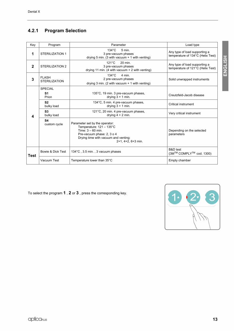
4.2.1 Program Selection
Key Program Parameter Load type
1 STERILIZATION 1 134°C 5 min.
3 pre-vacuum phases drying 5 min. (3 with vacuum + 1 with venting)
Any type of load supporting a temperature of 134°C (Helix Test)
2 STERILIZATION 2 121°C 20 min.
3 pre-vacuum phases drying 11 min. (4 with vacuum + 2 with venting)
Any type of load supporting a temperature of 121°C (Helix Test)
3 FLASH STERILIZATION
134°C 4 min. 2 pre-vacuum phases
drying 3 min. (2 with vacuum + 1 with venting) Solid unwrapped instruments
SPECIAL S1 Prion
135°C, 19 min. 3 pre-vacuum phases, drying 3 + 1 min. Creutzfeld-Jacob disease
S2 bulky load
134°C, 5 min. 4 pre-vacuum phases, drying 3 + 1 min. Critical instrument
S3 bulky load
121°C, 20 min. 4 pre-vacuum phases, drying 4 + 2 min. Very critical instrument
4 S4 custom cycle Parameter set by the operator:
Temperature: 121 – 135°C Time: 3 – 60 min. Pre-vacuum phase: 2, 3 o 4 Drying time with vacuum and venting: 2+1, 4+2, 6+3 min.
Depending on the selected parameters
Bowie & Dick Test 134°C , 3.5 min. , 3 vacuum phases B&D test (3MTM COMPLYTM cod. 1300) Test
Vacuum Test Temperature lower than 35°C Empty chamber
To select the program 1 , 2 or 3 , press the corresponding key.

Dental X
14 apticaPLUS
ENG
LISH
To select any program of the option 4 , hold pressed the key 4 and press key 1 or 2 (up or down arrow) to display the choice (S1, S2, S3 or S4) on the PRESS display.
The displays will show for 5 seconds the parameters of the selected cycle.
max.
min.
max.
S1......S4
4.2.2 Running the cycle Launch the selected cycle by pushing the key START/STOP.
The programs 3 and S4 could not guarantee the sterilization process for any type of load; to launch these type of cycles hold down 3 (or 4) and select the START/STOP keys.
The parameter values of the selected program are shown once again for 10 seconds, then the sterilizer starts and runs in automatic way the phases making up the cycle. The various steps of the cycle are microprocessor controlled and sequentially shown on the display; in this way the operator can monitor the sterilization phases and times:
• Led VACUUM turns on
• Display TIME starts to record the cycle duration
• Display PRESS shows the pressure in the chamber
• Display TEMP shows the temperature in the chamber
• The key Led of the selected program (1, 2, 3 or 4) starts to blink.
During this first phase a water dose is entered into the chamber and the microprocessor enables the heating phase. The led VACUUM blinks signaling the pre-vacuum phase that will be repeated for a total time variable from 5 and 10 minutes depending on the chamber condition and the load.. Pump operation may be slightly noisy.
Pre-VACUUM phase (chamber water entry, vacuum and heating)

Dental X
apticaPLUS 15
ENG
LISH
For unwrapped solid instruments we recommend to use the cycle 3. In this way the sterilization time will be faster, and power consumption reduced.
Reached the pre-set parameter values, VACUUM Led turns OFF, and STERILIZE Led turns ON. Display TIME starts the countdown marking the time remaining for the sterilization process, and the other displays show the temperature and pressure values of the steam.
Ended the sterilization phase, starts the decompression phase, and display PRESS shows the pressure value decreasing down to 0. Again, display TIME will start the countdown of the decompression phase. Based on previous experiences, the decompression time has been slightly extended in order to minimize the thermal shock consequent to the steam changing its state.
When decompression is through, Led STERILIZE starts to blink to signal the process has been completed. At the same time Led DRYING turns ON, signaling the start of the drying cycle. Throughout this phase, the heaters hold the chamber warm according to a microprocessor-controlled differentiated logic, the vacuum pump comes into operation again to suck in all residual steam. Display TIME shows the countdown of this phase.
Follows the forced ventilation through the bacterial filter; the countdown of this phase is signaled on the display TIME.
As soon as the drying is over, Led DRYING turns OFF, and Led READY and STERILIZE turn ON. A 10-second alert signal is generated to draw the attention by the operator. The heaters are switched to reduced power until the door is open. Display TIME shows the total time of the cycle, displays TEMP. and PRESS show the current temperature and pressure of the chamber.
At the end of the cycle 3 or S4, only Led READY will light (not the Led STERILIZE) to signal that the cycle selected by the operator does not guarantee the sterilization of any type of load.
The process is over, the door can be open and the load recovered.
Be careful !, both instruments and chamber are hot !
On opening the door, the displays will show again the current time, chamber temperature and pressure. From this point the sterilizer is ready for a new cycle.
If a printer is connected and ready, a report will be issued during the cycle phases with the more significant information; the report can be filed as proof of the sterilization process performed.
The operator can arrange a new load and start a next sterilization cycle, taking the advantage of shorter warming-up time as the chamber is already warm, or press the key POWER to switch in stand-by status the unit (OFF state).
If the door is not opened or no key is pressed within 30 minutes from the end of the cycle, the sterilizer will switch automatically in stand-by (OFF state).
Should any failure or error occur during the cycle, Led ALARM turns ON and the TIME display will show alarm type and code (see chapter ALARM).
STERILIZE phase
DRYING phase
END – Led READY and STERILIZE turn ON

Dental X
16 apticaPLUS
ENG
LISH
4.3 STOPPING THE CYCLE IN ADVANCE
In case you have to stop the sterilization cycle in advance, press START/STOP key.
Display TIME shows MANU STOP.
Before opening the door, make sure that the pressure value shown on display PRESS is equal to zero 0. A safety device will anyway prevent from opening the door if the chamber is over-pressurized.
Remove the instruments and check for the presence of water into the chamber. In case of wrapped instruments, we suggest to replace with new bags.
Wait 10 minutes before loading the chamber again so as to allow the water to evaporate and be drained. Wipe the chamber with a cloth.
4.4 TOPPING UP THE MAIN TANK - DRAINING THE USED WATER TANK
The sterilizer is fitted with two 2,5-liters tanks: main tank for the demineralized water and recovery tank for the used water. The hydraulic system does not reuse the steam generated during the sterilization process; this steam is collected in a recovery tank and periodically must be drained. This mode of operation involves the progressive emptying of the main tank and the filling of the recovery tank.
4.4.1 Topping up the main tank The average water consumption for each sterilization cycle is 150-260 cc, hence 10-15 cycles can be completed with a full tank loading.
The switching-on of Led MIN relating the main tank informs the operator the water level is insufficient to perform a new process.
Provides for the topping up of the main tank, taking care to not exceed the grid limit of the hole. The lighting of Led MAX and a 7 beep warns that the tank is full.
.
Main tank Recovery tank
max.
min.
max.

Dental X
apticaPLUS 17
ENG
LISH
4.4.2 Draining the recovery tank Led MAX relating the recovery tank level warns that the overflow limit has been reached. In this case:
• Get a bucket or a tank with a capacity of at least 2,5 liters,
• Fit the draining hose into the gray fast fitting (unthreaded side),
• Wait until the water has been completely drained,
• Unfit the hose pushing the ring nut against the machine and drawing the hose.
max.
min.
max.
4.5 SOUND WARNING SIGNALS
In order to make sterilizer operation even simpler and more user-friendly, some acoustic signals will draw the operator’s attention on occurring the main steps of the sterilization cycle:
• Whenever a key is pressed, a short beep is generated.
• 3 beeps indicate the end of the switching-on autotest.
• 10 beeps indicate the end of the sterilization process.
• 1 intermittent beep indicates that the door has not been properly closed.
• 30-seconds beep warns the operator if an alarm occurs during the cycle.
• 7 beeps indicate that the main tank is full.
Plugging Unplugging

Dental X
18 apticaPLUS
ENG
LISH
5. PROGRAMMING 5.1 SETTING DATE AND TIME
Press key SET and use keys 1 and 2 to fine adjust the values shown on the display. Whenever key SET is pressed, a different function is controlled:
PRESS THE KEY
MESSAGE ON TIME DISPLAY PARAMETER
SET SET YEAR YEAR
SET SET MONTH MONTH
SET SET DAY DAY
SET SET HOUR HOUR
SET SET MIN MINUTES
USE KEY
to increase the value, or
to decrease the value
SET Exit the programming mode
Example: to adjust the current hour, press key SET four times and set the time through key 1 or 2.
5.2 SETTING MEASUREMENT UNIT AND OPTIONS
Press key SET and 3 to enter the set-up mode
The display PRESS shows: SET UNIT °C or SET UNIT °F The display TIME shows: L1 L2 L3 L4 L5 L6
Use key 1 to set the desired temperature measurement unit Press more times key 2 L1 = Italian L2 = English L3 = Spanish L4 = French L5 = German
L6 = saving the sterilization cycles on PC (through a link with an external optional interface)
Press key SET
The display PRESS shows: SET UNIT BAR or SET UNIT PSI
Press 1 to set the desired pressure measurement unit
Press again the key SET to exit the programming mode The sterilizers are generally factory pre-set for the measurement units used in the destination countries (°C, bar, L2).
to set the language of the printing report

Dental X
apticaPLUS 19
ENG
LISH
5.3 SETTING THE SPECIAL CYCLE S4
The operator can set a special customized sterilization cycle as follows:
Press keys SET and 4 in a sequence
display PRESS shows: SET TEMP
Set the process temperature value between 121 and 135 °C through keys 1 and 2
Press key SET once again display PRESS shows: SET TIME
Set the process time between 3 and 60 minutes through keys 1 and 2
Press key SET once again display PRESS shows: VAC or DRY
Set the number of vacuum phases (2, 3 or 4) by key 1;the value is shown close to message VAC.
Set the duration of the drying phase (vacuum + ventilation = 2+1, 4+2 or 6+3 minutes) by key 2; the value is shown close to message DRY.
Press key SET again to exit the programming mode. The parameter values of the SPECIAL cycle are automatically stored and maintained until new values are set through the same procedure.
Depending on the selected time + temperature value combination, the processed cycle may differ from class B sterilization program. We recommend to test the sterilization performance by means of adequate procedures. At the end of the cycle S4, only Led READY will light (not Led STERILIZE) to signal that the efficiency of the cycle selected by the operator has not been tested by the manufacturer. The printout will indicate “Disinfection” also if the parameter values set by the operator are congruent for a sterilization process.

Dental X
20 apticaPLUS
ENG
LISH
6. MAINTENANCE 6.1 PERIODIC CLEANING CYCLE
A proper maintenance program is essential prerequisite for the smooth operation of the sterilizer. To this regard, it is important to carry out the following cleaning routine at least every set of 60 cycles.
For more clarity, every 60 cycles without any intermediate maintenance, the sterilizer displays the warning <NEED CLEANING >. CAUTION: Carry out the chamber cleaning with the unit cold.
1. Put in stand-by mode the sterilizer by pushing on the key POWER (OFF on the display).
2. IMPORTANT: Take the basket and the trays out of the chamber and wash them with an ordinary dish washing powder; rinse with water and wipe.
DO NOT USE ABRASIVE DETERGENTS
3. Using the supplied spanner, unscrew the outflow filter inside the chamber and clean with a soft brush and air spray.
4. Reassemble and screw down by hand the filter (the spanner is not necessary).
5. Put one cleaning tab into the chamber (without trays) and close the door.
6. Hold down the key START/STOP and push the key POWER to start the automatic cleaning cycle (message CLEANING on the display); the vacuum pump will be enabled.
7. This cycle takes a time from 10 to 15 minutes and cannot be interrupted after its starting (panel keys disabled).
During the cleaning cycle do not open the chamber as the steam would exhaust.
8. Ended the cycle, Led READY will turn on.
Unscrew and clean the filter

Dental X
apticaPLUS 21
ENG
LISH
9. Open the door and drain the used-water tank by using the supplied tube into the fast fitting point.. Ended the draining, remove the tube from the fast fitting point.
10. Fill the main tank with demineralized water.
11. Wipe inside the chamber with a clean cloth slightly soaked with demineralized water and pure alcohol. Do not use sponges, brushes or abrasive steel wool.
12. Close the door and switch off the unit with the key POWER.
The sterilizer is ready for a new set of sterilization cycles.
6.2 CLEAN THE INSTRUMENT BEFORE STERILIZING
In order to extend the life of the sterilizer, we recommend to carry out an accurate cleaning of the instruments, as one of the major causes of an early wear of the unit is the settlement and accumulation of debris and fragments for inadequately instrument cleaning, and consequent stains, fouling and progressive clogging of filters, electrovalves and hydraulic circuit.
We remind you that the electronic control system can keep track the number of maintenance cycles actually performed. The lacking of appropriate and regular maintenance according to the above guidelines may require early repair and involve warranty lapse.
Drain the used-water tank

Dental X
22 apticaPLUS
ENG
LISH
6.3 H2O FILTER MAINTENANCE / REPLACEMENT
To carry out the cleaning or the replacement of the filter mounted left side of the stainless steel front panel, proceed as follows:
1. Empty the tank by plugging the hose (unthreaded end) into the fast fitting point on the front panel,
2. Use a coin to unscrew the cap closing the filter seat; pay attention for the overflow of the water that could be in the tank connecting tube. Unscrew the filter using the supply spanner,
3. Clean the filter with compressed air (or ultrasonic cleaner) or replace if the filter is damaged,
4. Mount the filter into the seat then the cap by a coin without tightening both excessively,
5. Fill the tank with demineralized water as for the standard operation.
6. With the unit in standby state (OFF on the display), hold pressed the key and select the key POWER. The equipment will provide for the
automatic exhausting of the residual air from the filter. This procedure ends with the lighting of the signaling READY.
5
3
4
2
1

Dental X
apticaPLUS 23
ENG
LISH
6.4 REGULAR STERILITY CHECKS
For a correct utilization of the sterilizer, it is advisable to carry out sterility tests regularly. In particular, we suggest to carry out the microbiologic tests, Bowie & Dick and Helix test that may be easily find on the market. For carrying out these tests, refer to the instructions and indications provided by the suppliers.
For the microbiologic tests, we recommend to place biological indicators at different points of the sterilization chamber in order to verify the homogeneity of the sterility conditions. For more information, please call your retailer or Dental X directly.
The sterilizers have been submitted to strict tests of sterility by University of Siena (Institute of Hygiene and Human Anatomy). According to the international standard, all the sterilizers are moreover tested in factory with the above tests.
6.4.1 Bowie & Dick Test The test can be performed at any time with sterilizer turned on and operating. - Load the sterilizer with a B&D test (i.e. 3MTM COMPLYTM code 1300)
according to the standards for the test procedure. - With the unit switched-on, press key TEST and then key START. Test runs with cycle parameters of 134°C, sterilization time 3,5 min. and 3 pre-vacuum phases. 6.4.2 Vacuum Test Take care to carry out the test at the beginning of the working day in order to check the leakproof of the chamber and vacuum system. The test can be enabled on condition that the machine is in stand-by mode (signaling OFF on the display) and the internal temperature lower than 35°C (normal conditions at the beginning of the day). - Press the key TEST - The vacuum test starts automatically and takes about 15 minutes. - Ended the test, the sterilizer goes back in stand-by mode; press key
POWER to set for a new cycle. In case of negative result, alarm display will show the signaling TEST FAIL to warn for an insufficient vacuum condition in the chamber (see chapter 8 - Alarms).
max.
min.
max.
Dental X
24 apticaPLUS
ENG
LISH
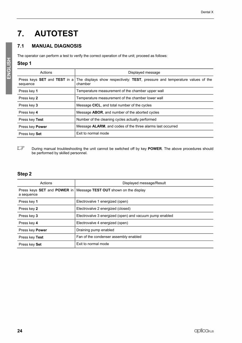
7. AUTOTEST 7.1 MANUAL DIAGNOSIS
The operator can perform a test to verify the correct operation of the unit; proceed as follows:
Step 1
Actions Displayed message
Press keys SET and TEST in a sequence
The displays show respectively: TEST, pressure and temperature values of the chamber
Press key 1 Temperature measurement of the chamber upper wall
Press key 2 Temperature measurement of the chamber lower wall
Press key 3 Message CICL, and total number of the cycles
Press key 4 Message ABOR, and number of the aborted cycles
Press key Test Number of the cleaning cycles actually performed
Press key Power Message ALARM, and codes of the three alarms last occurred
Press key Set Exit to normal mode
During manual troubleshooting the unit cannot be switched off by key POWER. The above procedures should be performed by skilled personnel.
Step 2
Actions Displayed message/Result
Press keys SET and POWER in a sequence
Message TEST OUT shown on the display
Press key 1 Electrovalve 1 energized (open)
Press key 2 Electrovalve 2 energized (closed)
Press key 3 Electrovalve 3 energized (open) and vacuum pump enabled
Press key 4 Electrovalve 4 energized (open)
Press key Power Draining pump enabled
Press key Test Fan of the condenser assembly enabled
Press key Set Exit to normal mode

Dental X
apticaPLUS 25
ENG
LISH
7.2 AUTOMATIC TROUBLESHOOTING AT THE SWITCHING-ON
Switching on the unit, an automatic 15-sec. duration troubleshooting cycle is started. 3 beeps are generated at the end of this autotest.
During this test the main components of the sterilizer are sequentially controlled, and Led’s turned on (included the Alarm signaling) for a few seconds.
If the test is positive, message Card Good will be shown. Whatever fault detected is shown on the display and stored according to the alarm codes listed in table C (see chapter ALARM).
To skip the troubleshooting, press any key as soon as the sterilizer is switched-on.
7.2.1 Water quality control
In order to prevent fail due to poor quality of the demineralized water, the new apticaPLUS is equipped with a special water quality control.
The control, based on water conductivity measurement, is performed at the autoclave switching-on and on condition that the machine is cold and the water tank is full.
At the end of the initial autotest the display will show “H2O good” if the conductivity is below 15 µS and “H2O hard” if above 15 µS.
ATTENTION
The negative result of the water quality control does not stop the operation of the sterilizer, but it is strictly recommended to replace the water.

Dental X
26 apticaPLUS
ENG
LISH
8. ALARMS 8.1 GENERAL
The supervisory system of the sterilizer monitors the phases of the cycle and the operation of the sterilizer’s elements. Any possible trouble occurred during the cycle is detected, reported and signaled on the alarm display and by a warning tone.
To make easier the interpretation and identification, the alarms have been divided into four classes, as shown in tables A, B, C and D.
8.2 WARNING MESSAGES
Table A lists the warning messages.
TABLE A
Displayed message
Cause Recommended action
OPEN DOOR Door not opened at the end of the cycle.
Start command entered with the door open.
Open the door.
Close the door
FAIL Failed cycle See table C
DRY FAIL
Drying phase not completed due to manual interference (the load has been removed before the drying cycle completion). However the sterilization process has been achieved.
Press key STOP
ADD H2O Insufficient water in the main tank (the message appears before starting a cycle) Top up the main tank
FULL H2O The recovery tank is full (the message appears before starting a cycle) Empty the water recovery tank
MANU STOP The cycle has been manually interrupted. The sterilization process has not been completed
Wipe the chamber, and start the cycle again
BLAC OUT Power supply black-out during the cycle Verify the AC plug and socket. Dry the chamber and repeat the cycle.
NEED CLEANING 60 cycles without any intermediate cleaning cycle Perform the cleaning cycle (see Chapter 6.1)
NEED SERVICE One year from the first installation or over 1000 cycles performed without the service check-up
The warning disappears as soon as a next cycle is selected, but will appear again at the next switching on.
Call for a complete check by a qualified technical service; the message will be reset after the servicing.
NEED INST Need for the installation procedure Perform the installation procedure (see Chapter 3.2)
NEED TEST Detected a pre-warning alarm See table B
TEST FAIL Negative result of the vacuum test Clean the door gasket and repeat the test.
Call for a technical service

Dental X
apticaPLUS 27
ENG
LISH
8.3 PRE-WARNING ALARMS
The alarms listed in Table B do not stop the sterilizer operation, but warn that the detected problem might interfere with the correct sterilizer performance. The trouble should be checked and the recommended action promptly performed. These alarms are coded and follow the message NEED TEST. Example: Need Test cd 1.
TABLE B
Alarm code Cause Recommended solution
cd 1 Outflow filter dirty Clean or replace the filter
cd 2 Slow heating of the upper surface of the chamber
Perform a cycle with reduced load. In case, call for a technical service. Verify the mains voltage.
cd 3 Slow heating of the lower surface of the chamber
Perform a cycle with reduced load. In case, call for a technical service. Verify the mains voltage.
cd 4 Water dose distributor blocked
Front H2O filter dirty
Impurities in the main tank.
Carry out the H2O filter maintenance.
Carry out the standard maintenance routine!
cd 5 Water-charge valve dirty If the problem occurs more than 3 times, call for a technical service
cd 6 Bacterial filter clogged Replace the filter
cd 7 Vacuum phase too slow Wipe the chamber and perform a cleaning cycle

Dental X
28 apticaPLUS
ENG
LISH
8.4 ABORTED CYCLE ALARMS
The alarms listed in Table C signal a detected fault that prevent the sterilization process from being completed.
Identify the fault and the recommended action on the table.
The alarm condition is signaled by the lighting of the Led ALARM, and on the upper display by the flashing message FAIL followed by the code number of the detected alarm.
Example: FAIL AL 6
TABLE C
Alarm code Cause Recommended solution
AL 1 Fault of the electrovalve 1 Call for a technical service
AL 2 Fault of the electrovalve 2 Call for a technical service
AL 3 Fault of the electrovalve 3 Call for a technical service
AL 4 Fault of the electrovalve 4 Call for a technical service
AL 5 The pressure has not reached the set-point value within the preset time
Excess of load or pressure leakage. Carry out the cleaning cycle
AL 6 Too long time during the initial vacuum phase Perform the cleaning cycle
AL 7 The door was opened after the start of the cycle Make sure that the door is correctly closed.
AL 8 Air into the sterilization chamber Verify the door tightness. Clean the gasket.
AL 9 Interruption of the countdown for over 60 sec. during the sterilization phase
Verify the door tightness. Perform the cleaning cycle and, if needed, clean the door gasket. Perform the vacuum test
AL 10 Too high pressure Call for a technical service.
AL 11 Too low pressure Verify the door tightness. Perform the cleaning cycle, if needed. Perform the vacuum test
AL 12 Temperature out the normal range Perform the cleaning cycle
AL 13 Fault of the chamber temperature sensor Call for a technical service
AL 14 Fault of the temperature upper sensor Call for a technical service
AL 15 Fault of the temperature lower sensor Call for a technical service
AL 16 Fault of the pressure sensor Call for a technical service
8.5 CLASS B ADDITIONAL ALARMS
TABLE D
Alarm code Phase involved Cause Recommended solution
18 Drying phase Drying interrupted Dry the instruments
31 Drying phase Vacuum not sufficient Excess of load
NOTE: The Class B alarms may occur in the programs 1, 2, S1, S2 and S3 only.

Dental X
apticaPLUS 29
ENG
LISH
9. CONNECTIONS 9.1 PRINTER CONNECTION
The sterilizer may be provided with a printer connection port for a printout report of the sterilization process. The use of the printer, mandatory in some countries, goes to be more and more frequent as the growing need to certify, for the legal medical profile also, the sterilization effectiveness of the instruments. The printer connector is mounted on the rear panel of the sterilizer.
Use a standard cable with max. length of 3 m.
It is possible to interface apticaPLUS with any printer type (DOS, CENTRONIX Standards) provided with a parallel port. Most of the printer on the market can support this standard. Please contact DENTAL X for further information.
1. Switch-on the printer,
2. Switch-on the sterilizer.
The report will be printed during the process and with the following information:
date and time of the process - cycle number - selected program and parameters - cycle type: sterilization or disinfecting – start/end time of the sterilization phase - end time of the drying phase
In case of trouble or cycle interruption, the printout will report the message ABORTED CYCLE - NOT STERIL with the indication of the detected alarm type.
Remember to switch off the printer at the end of the working day.
To set the language for the printed report, see chapter 5. The PRINTER port must be only used for connecting a printer device.
Moreover the printer port allows, via a dedicated interface, the connection to a computer for the storing of the sterilization cycles. Please contact the retailer or Dental X for further information.
9.2 PC CONNECTION
The sterilizer is fully microprocessor controlled and may be connected to a standard PC. Trough a dedicated user interface, this feature allows both to perform more accurate tests and a new approach to service and certification aspect.
By a special SW tool used by the authorized service centers it is possible to know all the main data of the machine, and allow a fast troubleshooting and repairing at reduced cost.
Moreover, the system allows the connection via modem to an authorized service center performing a remote check-up and a periodic certification of effective operation of the sterilizer.
Do not connect by yourself any device not provided and authorized by the manufacturer.


Änderungen im Zuge technischer Weiterentwicklung vorbehalten.
We reserve the right to make any alterations which may be due to technical improvements.
Sous rèserve de modifications dues au progrès technique.
Reservados los derechos de modificatiòn en virtud del progreso tècnico.
Ci riserviamo il diritto di apportare modifiche a seguito di migliorie tecniche.
Copyright Dental X 2003 Printed in Italy
DENTAL X s.r.l. Via Marzotto 11 36031 Dueville (VI) Italy Tel. +39 444 367400 Fax +39 444 367436 e-mail: [email protected] http://www.dentalx.it
SERVICE Italy - Tel. +39 444 367415 Foreign - Tel. +39 2 76275234 country