april 2014 geotechnical and structures laboratory · solves the nation’s toughest engineering and...
TRANSCRIPT

ERD
C/G
SL S
R-14
-1
Levels of Autonomy and Autonomous System Performance Assessment for Intelligent Unmanned Systems
Geo
tech
nica
l and
Str
uctu
res
Labo
rato
ry
Phillip J. Durst and Wendell Gray April 2014
Approved for public release; distribution is unlimited.

The US Army Engineer Research and Development Center (ERDC) solves the nation’s toughest engineering and environmental challenges. ERDC develops innovative solutions in civil and military engineering, geospatial sciences, water resources, and environmental sciences for the Army, the Department of Defense, civilian agencies, and our nation’s public good. Find out more at www.erdc.usace.army.mil.
To search for other technical reports published by ERDC, visit the ERDC online library at http://acwc.sdp.sirsi.net/client/default.

ERDC/GSL SR-14-1 April 2014
Levels of Autonomy and Autonomous System Performance Assessment for Intelligent Unmanned Systems
Phillip J. Durst and Wendell Gray Geotechnical and Structures Laboratory US Army Engineer Research and Development Center 3909 Halls Ferry Road Vicksburg, MS 39180-6199
Final report Approved for public release; distribution is unlimited.
Prepared for US Army Test and Evaluation Command Aberdeen, MD 21001

ERDC/GSL SR-14-1 ii
Abstract
This report provides an overview of the current state of autonomous system testing and evaluation methodologies and levels of autonomy for intelligent unmanned systems (UMSs). It is meant to be an extensive review of all past and ongoing efforts to define autonomy and set levels of autonomy for unmanned systems as related to military applications. Presented within are the current performance metrics for autonomous systems, the current standards that have been adopted for autonomous systems, and the leading frameworks for assessing levels of autonomy and autonomous mission performance. Currently, no one framework for defining UMS autonomy level has been adopted by the robotics community. This report summarizes the current research in this area and provides recommendations on the steps required to adequately define autonomy and autonomous mission performance.
DISCLAIMER: The contents of this report are not to be used for advertising, publication, or promotional purposes. Citation of trade names does not constitute an official endorsement or approval of the use of such commercial products. All product names and trademarks cited are the property of their respective owners. The findings of this report are not to be construed as an official Department of the Army position unless so designated by other authorized documents. DESTROY THIS REPORT WHEN NO LONGER NEEDED. DO NOT RETURN IT TO THE ORIGINATOR.

ERDC/GSL SR-14-1 iii
Contents Abstract .......................................................................................................................................................... ii
Figures and Tables ........................................................................................................................................ iv
Preface ............................................................................................................................................................. v
Acronyms ........................................................................................................................................................ vi
1 Introduction ............................................................................................................................................ 1 Background .............................................................................................................................. 1 Purpose ..................................................................................................................................... 1 Scope ........................................................................................................................................ 1
2 Standards and Performance Metrics for UMS ................................................................................ 3 Overview ................................................................................................................................... 3 Unmanned ground vehicle (UGV) standards ........................................................................... 3
The Joint Architecture for Unmanned Systems (JAUS) .............................................................. 3 The 4D/RCS reference architecture ........................................................................................... 4
Unmanned ground vehicle (UGV) performance metrics ......................................................... 5 Unmanned aerial vehicle (UAV) standards .............................................................................. 6 Unmanned maritime vehicle system (UMVS) standards ........................................................ 8 Summary .................................................................................................................................. 8
3 Contextual Autonomy Level Evaluation Methodologies ............................................................... 9 Introduction .............................................................................................................................. 9 The Autonomy Levels for Unmanned Systems (ALFUS) framework ....................................... 9
ALFUS detailed model autonomy level tool ................................................................................ 9 ALFUS summary model autonomy level tool ............................................................................ 11 ALFUS shortcomings and inapplicability for current T&E ........................................................ 13
Summary ................................................................................................................................ 14
4 Non-Contextual Autonomy Level Evaluation Methodologies ..................................................... 15 Introduction ............................................................................................................................ 15 A generic, high-level model of UMS architecture .................................................................. 15 The Non-Contextual Autonomy Potential (NCAP) .................................................................. 17
The NCAP autonomy level .......................................................................................................... 17 The NCAP autonomous potential .............................................................................................. 19 NCAP shortcomings and inapplicability for current T&E .......................................................... 19
Summary ................................................................................................................................ 19
5 Conclusions .......................................................................................................................................... 21
References ................................................................................................................................................... 22
Report Documentation Page

ERDC/GSL SR-14-1 iv
Figures and Tables
Figures
Figure 1. The hierarchical structure of JAUS. .............................................................................................. 4 Figure 2. Internal structure of a node within the 4D/RCS architecture. ................................................. 5 Figure 3. The ALFUS Contextual Autonomy Capability (CAC). ................................................................. 10 Figure 4. Example application of the ALFUS to an unmanned ground vehicle for the simple reconnaissance mission (Huang et al. 2005). ......................................................................................... 11 Figure 5. ALFUS summary model overview. ............................................................................................. 12 Figure 6. ALFUS summary model autonomy level trend. ........................................................................ 12 Figure 7. A high-level, non-hierarchical architecture model for intelligent UMS. ................................. 16 Figure 8. The NCAP autonomy levels within the framework of the UMS architecture model. ........... 18
Tables
Table 1. Five levels of interoperability defined by the STANAG 4586. ..................................................... 7 Table 2. NCAP autonomy level for several typical UMS. .......................................................................... 18

ERDC/GSL SR-14-1 v
Preface
This report was compiled for Kelly Swinson, ASTERS Study Director, Unmanned Ground Vehicle (UGV) Test Officer, US Army Aberdeen Test Center, Aberdeen Proving Ground, MD, as part of the Autonomy System Testing and Evaluation Study (ASTERS). The objective of this report is to provide an overview of the current state of testing, evaluation, and performance assessment of ground, air, and sea autonomous unmanned systems, with a primary focus on autonomous ground vehicles (AGVs).
This report was prepared by Phillip J. Durst, US Army Engineer Research and Development Center (ERDC) Mobility Systems Branch (MSB), Engineering Systems and Materials Division (ESMD), Geotechnical and Structures Laboratory (GSL) and Wendell Gray, GSL Executive Office. The work was conducted under the general supervision of Randolph A. Jones, Chief, MSB; Dr. Larry N. Lynch, Chief, ESMD; Dr. William P. Grogan, Deputy Director, GSL; and Dr. David W. Pittman, Director, GSL.
COL Jeffrey R. Eckstein was the Commander of ERDC, and Dr. Jeffery P. Holland was the Director.
The authors would like to thank the North Atlantic Treaty Organization Applied Vehicle Technologies 175 Workgroup for their contribution to this work, in particular Michael Trentin of Defence R&D Canada and Joao Caetano of the Portuguese Air Force.

ERDC/GSL SR-14-1 vi
Acronyms
AGV Autonomous Ground Vehicle
AL Autonomy Level
ALFUS Autonomy Levels for Unmanned Systems
ASTERS Autonomous Systems Test and Evaluation Requirements Study
ASTM American Society for Testing and Materials
ATEC US Army Test and Evaluation Command
AVT Applied Vehicle Technology
C4I Command, Control, Communication, Computer, and Intelligence
CAC Contextual Autonomy Capability
DLI Data Link Interface
ERDC US Army Engineer Research and Development Center
ESMD Engineering Systems and Materials Division
GCS Ground Control Station
GSL Geotechnical and Structures Laboratory
JAUS Joint Architecture for Unmanned Systems
LOI Level of Interoperability
MSB Mobility Systems Branch
NATO North Atlantic Treaty Organization
STANAG Standardization Agreement

ERDC/GSL SR-14-1 vii
NCAP Non-Contextual Autonomy Potential
NIST National Institute for Standards and Technology
OCU Operator Control Unit
SAE Society of Automotive Engineer
T&E Testing and Evaluation
UAV Unmanned Aerial Vehicle
UGV Unmanned Ground Vehicle
UMS Unmanned System
UMVS Unmanned Maritime Vehicle System
USAR Urban Search and Rescue
USV Unmanned Surface Vehicle
UUV Unmanned Undersea Vehicle
VSM Vehicle Specific Module

ERDC/GSL SR-14-1 1
1 Introduction
Background
The ground vehicle test and evaluation (T&E) community currently faces a number of challenges. Three of the biggest challenges are user acceptance and trust, effective T&E, and defining autonomy in a comprehensive and quantitative way. User acceptance and trust in the system can be enabled through sufficient testing and providing proof to the user community that the system is safe to be operated in the intended environment. The Autonomous System Testing and Evaluation Requirements Study (ASTERS) was initiated to address these challenges and provide a complete study of the current and future needs of the T&E community to accurately and reliably test the safety and performance of autonomous ground vehicles (AGV) for the armed services.
In particular, defining autonomy for AGVs and providing a means for assessing an AGV’s autonomy level (AL) is a critical knowledge gap within the T&E community. Much basic research has addressed AL for unmanned systems (UMSs), but no definitive ALs have been established to date, and no standardized test methods for autonomous UMS have been developed for assessing performance. Furthermore, many of the proposed autonomy level frameworks offer limited applicability to military operations and are often overly complex and difficult to implement in a T&E environment.
Purpose
The purpose of this report is to provide a comprehensive review of autonomy levels for autonomous UMSs, with a particular focus on AGVs. This report does not provide an authoritative definition of autonomy or ALs but rather collects those AL and autonomous performance assessment methodologies proposed to date and provides details concerning the benefits and shortcomings of each methodology for military T&E applications.
Scope
A search of the literature reveals a wealth of proposed autonomy level definitions and performance assessment metrics, each with their own
ERDC/GSL SR-14-1 2
advantages and disadvantages and potential applications to military operations. This report will provide details on only a few of these performance metrics and AL methodologies, focusing on those that are the most developed, most often cited, and most applicable to military T&E efforts. In particular, two main methodologies will be presented: those that take into account the AGV’s mission and operational environment (contextual methodologies) and those that do not consider outside factors (non-contextual methodologies).

ERDC/GSL SR-14-1 3
2 Standards and Performance Metrics for UMS
Overview
Unmanned systems (UMS) is an emerging technology that is constantly advancing and expanding for novel applications in increasingly complex environments. One major consequence of the rapid advancement of UMS, particularly for military applications, is a lack of accepted standard T&E procedures. Several efforts have begun to address this lack of standards and reliable T&E for UMS, and details of the work to date in this area are presented in this chapter.
Unmanned ground vehicle (UGV) standards
Several standards have been proposed for UGVs, some of which have been adopted by the international community. These standards relate primarily to UGV software architecture and messaging formats with the goal of enabling interoperability. The two forerunning standards for UGV architecture are discussed in the following paragraphs.
The Joint Architecture for Unmanned Systems (JAUS)
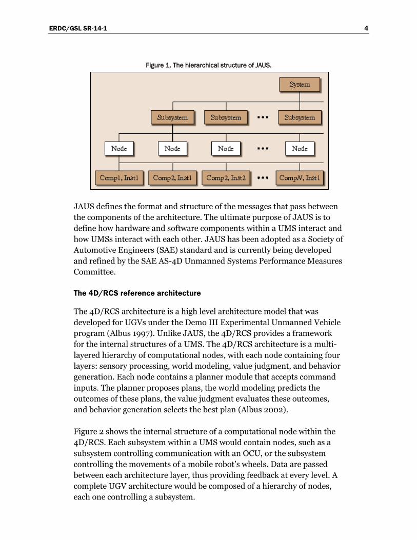
The Joint Architecture for Unmanned Systems (JAUS) is a standard messaging architecture for UMS (SAE 2011). JAUS was designed to promote interoperability between UMS subsystems and provide reusability and standardization for UMS platforms (Rowe and Wagner 2007). JAUS is based on a hierarchical organization, an overview of which is shown in Figure 1. While JAUS nominally relates to all UMS, it was developed and deployed almost exclusively for ground robotics.
In JAUS, a system is composed of multiple subsystems that are self-contained entities. Examples of a subsystem would be a single UGV or an operator control unit (OCU). Subsystems contain nodes, which are control systems. The nodes control the components, and the components are the physical systems that perform specific functions. An example of a node and component would be a motor that controls a panning camera sensor.
ERDC/GSL SR-14-1 4
Figure 1. The hierarchical structure of JAUS.
JAUS defines the format and structure of the messages that pass between the components of the architecture. The ultimate purpose of JAUS is to define how hardware and software components within a UMS interact and how UMSs interact with each other. JAUS has been adopted as a Society of Automotive Engineers (SAE) standard and is currently being developed and refined by the SAE AS-4D Unmanned Systems Performance Measures Committee.
The 4D/RCS reference architecture
The 4D/RCS architecture is a high level architecture model that was developed for UGVs under the Demo III Experimental Unmanned Vehicle program (Albus 1997). Unlike JAUS, the 4D/RCS provides a framework for the internal structures of a UMS. The 4D/RCS architecture is a multi-layered hierarchy of computational nodes, with each node containing four layers: sensory processing, world modeling, value judgment, and behavior generation. Each node contains a planner module that accepts command inputs. The planner proposes plans, the world modeling predicts the outcomes of these plans, the value judgment evaluates these outcomes, and behavior generation selects the best plan (Albus 2002).
Figure 2 shows the internal structure of a computational node within the 4D/RCS. Each subsystem within a UMS would contain nodes, such as a subsystem controlling communication with an OCU, or the subsystem controlling the movements of a mobile robot’s wheels. Data are passed between each architecture layer, thus providing feedback at every level. A complete UGV architecture would be composed of a hierarchy of nodes, each one controlling a subsystem.

ERDC/GSL SR-14-1 5
Figure 2. Internal structure of a node within the 4D/RCS architecture.
The 4D/RCS approach can be applied to individual subsystems within a UMS, and it has been successfully deployed on the Demo III experimental ground vehicle for world modeling and map building purposes (Hong et. al 2002) as well as path planning for an autonomous mobile robot (Lacaze 2002). The modular nature of the 4D/RCS allows specific components and their interactions to be placed inside the architecture to create a best solution for a given UGV platform and mission. The 4D/RCS architecture is prevalent throughout the literature, but is not a recognized standard and it does not provide a means for assessing performance.
Unmanned ground vehicle (UGV) performance metrics
Currently, performance assessment of UGVs is performed at multiple levels using many different methods. Individual component-level testing is performed on UGV hardware and software systems, while overall performance assessment is typically done through simulated missions or tasks, depending on the system.
Testing the UGV hardware involves testing the components of the platform’s mobility and hardware sensor systems. This includes testing individual sensors, the capabilities of the robotic platform, and human/robot interaction. Evaluation of software systems involves testing algorithms for accuracy, efficiency, speed, etc. Performance metrics and standard test procedures for this component level testing are lacking. Testing is usually conducted on a case-by-case basis with wide variations between experiments. Many modified legacy tests exist for evaluating ground robotic platforms addressing issues like mobility (Jacoff 2007), and much effort has been spent to develop metrics for quantitatively
ERDC/GSL SR-14-1 6
assessing UMS algorithms, for example Balaguer et al. 2007 and(Varsadan et al. 2009).
In terms of performance assessment, some metrics have been proposed and measured for evaluating UGV mission performance. However, few of the test methods have been adopted by the military T&E community. The only recognized standard test performance metrics and T&E procedures developed to date are a suite of tests for urban search and rescue ground robots backed by the American Society for Testing and Materials (ASTM). The ASTM tests were developed by the National Institute of Standards and Technology (NIST) for evaluating UGV performance conducting urban search and rescue (USAR) operations (ASTM 2008).
Unmanned aerial vehicle (UAV) standards
Interoperability standards for unmanned aerial vehicles (UAV) have been developed by multiple international workgroups. Foremost of these is the North Atlantic Treaty Organization (NATO) Standardization Agreement (STANAG) 4586, which provides a specification allowing members of the NATO alliance to share command and control of their UAVs (NATO 2007). Compliance with STANAG 4586 allows NATO member nations to jointly support military operations using their own UAVs and ground control station equipment. This increases interoperability and allows data and information processed by any member nation’s UAV to be shared in real-time through a common ground interface.
The NATO STANAG 4586 was created to address standard interfaces of UAV control systems. In its second edition, STANAG 4586 was conceptualized to promote interoperability between one or more control stations, UAV and their payloads, as well as the Command, Control, Communication, Computer and Intelligence (C4I) network, particularly in joint operational settings. STANAG 4586 attempts to accomplish this through implementing “standard interfaces.” The standard interfaces are communication message sets between the vehicle and a control station.
An operator interfaces with a Ground Control Station (GCS), which communicates through message sets in a Data Link Interface (DLI) with the UAV, specifically through the Vehicle Specific Module (VSM), which may or may not be on the actual vehicle. The VSM was introduced by the STANAG 4586 as an interface to translate between the STANAG 4586 interfaces and the vehicle’s proprietary interfaces.

ERDC/GSL SR-14-1 7
By enabling the interoperability of multiple vehicles from a common STANAG 4586 GCS, operators can interoperate UAVs with widely different performance characteristics and features. While it defines a generic control interface, STANAG 4586 uses configuration messages to request air vehicle and payload configuration information including:
• Expected ranges of vehicle platforms • Applicability of generic parameters to a vehicle • Availability of generic parameters from a vehicle • Extensibility of parameters
This information is used by the GCS to configure the air vehicle and payload operator displays to show only necessary information. While the GCS is required to support all generic functionality, it is expected to remove functionality not supported by a controlled vehicle. As the GCS cannot know all of the control logic for all vehicles, the VSM can be used to identify the current state of a vehicle’s parameters.
Private or user- defined messages can be implemented for the DLI to allow for tighter integration and customization and to accommodate functionality not found in the STANAG 4586. Five Levels of Interoperability (LOI) have been delineated for STANAG-compliant UAV systems. These levels are shown Table 1.
Table 1. Five levels of interoperability defined by the STANAG 4586.
Level 1 Indirect receipt/transmission of UAV-related payload data
Level 2 Direct receipt of Intelligence, Surveillance and Reconnaissance (ISR) data where "direct" covers reception of the UAV payload data by the unmanned control system when it has direct communication with the UAV
Level 3 Control and monitoring of the UAV payload in addition to direct receipt of ISR and other data
Level 4 Control and monitoring of the UAV, less launch and recovery
Level 5 Control and monitoring of the UAV, plus launch and recovery
However, the LOI do not represent levels of autonomy. They only imply how much interaction/authority one or more human controllers can expect to have with a system. Within each LOI, there could be additional layers of autonomy.

ERDC/GSL SR-14-1 8
Unmanned maritime vehicle system (UMVS) standards
Standards for Unmanned Maritime Vehicle System (UMVS) are currently being developed by the ASTM Committee F41 on Unmanned Maritime Vehicle Systems, which was formed in 2005 (ASTM 2013). This Committee addresses issues related to standards development for unmanned undersea vehicle (UUV) systems and unmanned surface vehicle (USV) systems to facilitate an interoperable, modular, and multi-functional family of platforms. Stakeholders include manufacturers of UMVS and their components, federal agencies, design professionals, professional societies, maintenance professionals, trade associations, financial organizations, and academia. The Committee, with a membership of approximately 165, currently has its standards published in the Annual Book of ASTM Standards, Volume 15.11. F41 has 5 technical subcommittees that maintain jurisdiction over these standards. The five technical subcommittees are:
1. F41.01: Autonomy and Control 2. F41.02: Communications 3. F41.03: Mission Payload Interface 4. F41.04: Data Formats 5. F41.90: Executive
Further information and access to the standards report documents generated by the F41 and its subcommittees can be found in ASTM 2013. As with JAUS, the F41 focuses on interoperability and modular design and not on performance evaluation metrics or UMVS bench testing.
Summary
A great deal of effort has been given to defining standards for UMS, with some success. However, this effort was directed almost exclusively towards interoperability standards to help drive modular and re-usable designs of UMS platforms and components. Few research efforts have been under-taken to try and define T&E procedures for assessing UMS performance. For T&E of AGVs to advance, this critical gap of performance assessment and bench testing methods must be addressed.

ERDC/GSL SR-14-1 9
3 Contextual Autonomy Level Evaluation Methodologies
Introduction
In addition to the standardization efforts mentioned in Chapter 2, several models have been proposed for assessing overall UMS performance as a function of autonomy level. In general, the autonomy level frameworks can be divided into two general categories, contextual and non-contextual. The most commonly referenced contextual model for assessing autonomous UMS performance is the Autonomy Levels for Unmanned Systems (ALFUS) framework (Huang et al. 2005).
The Autonomy Levels for Unmanned Systems (ALFUS) framework
The ALFUS is not a specific test or metric, but rather a model of how several different test metrics could be combined to generate an autonomy level. The ALFUS was initially presented at the 2004 International Society for Optics and Photonics (SPIE) Defence and Security Symposium (Huang et al. 2004), and the ALFUS workgroup continues to develop and refine the ALFUS as of writing. The framework includes the following four components.
1. Terms and definitions published in (Huang 2004) 2. Detailed model for autonomy levels 3. Summary model for autonomy levels 4. Guidelines, processes and use cases
During development, the user requirements for an autonomy level framework lead to the use of a two-model approach: the detailed and the summary models.
ALFUS detailed model autonomy level tool
The detailed model autonomy level tool was primarily envisioned to satisfy the need of accurately assessing the autonomy level of a UMS. It uses the three axis method of the Contextual Autonomous Capability (CAC), highlighted in Figure 3. Each axis refers to a metric group, which can be mission complexity, environmental complexity or human independence.

ERDC/GSL SR-14-1 10
These axes comprise scores from bench tests. For a given mission and environment, metrics are measured for the mission complexity, environmental complexity, and human independence of the UMS, and these metrics are combined to form a level of autonomy.
Figure 3. The ALFUS Contextual Autonomy Capability (CAC).
The CAC consists of a methodology to assess UMS autonomous capability to perform a certain mission in a predetermined environment. Currently, only a few standard bench tests exist to fill in the axes, and mathematical models do not exist to combining the metrics into a single level of autonomy.
Using this methodology, a spreadsheet-based software tool was proposed. The tool computes the final autonomy level using weighted metric scores that the users or developers enter manually. Following the example in Figure 4, the leftmost section of the spreadsheet contains the hierarchical task decomposition of a mission. In this example, the mission is to “Conduct Route Recon.” It can include the subtask “Tactically Follow” and “Recon Avenue of Approach.”
Each of the lower level subtasks (Level 2, in this example) is evaluated against all the three sets of the ALFUS metrics, which are shown in the middle columns of the figure. In this case only the “planning” for mission complexity and “workload” for human interface were presented. The metric scores are then weighted according to the number indicated on the right-next cell. For example, the score for the “Move to Standoff Position” subtask is ((6 * 1) + (8 * 1.2)) / 2 = 7.8.

ERDC/GSL SR-14-1 11
Figure 4. Example application of the ALFUS to an unmanned ground vehicle for the simple reconnaissance mission (Huang et al. 2005).
The subtask scores are then weighted and averaged. This calculates the scores for the higher-level tasks. The process continues and repeats for all subtasks until the overall score is calculated.
ALFUS summary model autonomy level tool
The summary or executive model for the ALFUS methodology consists of a simpler, easier to reference model that was developed to be used for general reference purposes. It consists of a 0 to 10 numeric scale that characterizes the autonomy level of a given UMS. It uses the outputs of the detailed model as its main inputs, as presented in Figure 5.
In order to better explain the generation of this model, the approach is outlined as follows:
1. Starting from the left-hand side, the model begins by summarizing the metric values for the particular autonomy levels
2. The model then derives definitions for each of the main levels, from the metric summary
3. The level descriptor is then created to facilitate human communication 4. The bottom box illustrates the fact that the Summary Model can be applied
to particular domains, in order to identify mission and task capabilities, while addressing autonomy level scales

ERDC/GSL SR-14-1 12
Figure 5. ALFUS summary model overview.
The general trend in the summary model is depicted in Figure 6. It illustrates the transitions of the levels of mission complexity, environmental difficulty, and human independence.
Figure 6. ALFUS summary model autonomy level trend.
As shown in Figure 6, the lowest level of autonomy is remote control, independent of the mission complexity or environment. Hence, the ALFUS defines the lowest level of autonomy as:
“Remote control of UMS wherein the human operator, without benefit of video or other sensory feedback, directly controls the actuators of the UMS on a continuous basis, from a location off the vehicle and via a tethered or radio linked control device using visual line-of-sight cues.” (Huang 2004)

ERDC/GSL SR-14-1 13
On the opposite side of the graph, one can find the full/intelligent autonomy. This is reached when all the three axes reach their full scales. The proposed definition for the highest level of autonomy is:
“Completes all assigned missions with highest complexity; understands, adapts to, and maximizes benefit/value/efficiency while minimizing costs/risks on the broadest scope environmental and operational changes; capable of total independence from operator intervention.” (ALFUS Framework 2005)
ALFUS shortcomings and inapplicability for current T&E
The proposed ALFUS framework provides the developer or user the capability of estimating the level of autonomy of one robot or a team of robots, using a spreadsheet. However, this methodology still has some drawbacks that prevent its direct implementation. The ALFUS methodology does not provide the tools to:
• Decompose the tasks in a commonly agreed-upon, standard way • Assess the interdependency between the metrics, as some of the
subtasks can apply to more than one metric • Allow metrics to be standardized in scoring scales: this will cause
subjective evaluation and criteria to influence the results across different robots, users or competing companies
• Integrate the metrics for a concise set of indices for the autonomy levels
Another important issue is related to the fact that the highest level of autonomy might not be the most desirable operational level for several robots, missions or environments. Sometimes supervised autonomy or direct control over the robot (assuring it will not lose its communications and sensors data link) will guarantee the best mission performance. For example, a fully autonomous ground vehicle will probably behave worse than a teleoperated robot in a bomb deactivation mission. For an unmanned aerial vehicle, a fully autonomous intelligent asset does not assure the best mission completion status in the case of an ever changing scenario or even a time sensitive target.

ERDC/GSL SR-14-1 14
Summary
Work on the ALFUS framework is ongoing, with some effort of the SAE JAUS workgroup being given to developing the bench tests necessary for filling in the three axes of the CAC. While the ALFUS is continuing to be refined and applied to a limited extent, progress has been slow, and many challenges still remain to be addressed before the ALFUS can become a useful measure of autonomy.
In terms of T&E applications, the ALFUS remains too vague and too complex. While it provides some general guidelines concerning what to test, including the UMS platform and its operational environment and operator concerns, it does not provide any guidelines describing test procedures. The complexity the ALFUS adds to the T&E process by requiring the environment metrics to be measured, which hampers the ability to assess autonomy for a broad range of applications. These shortcomings of the ALFUS led to the development of the simpler, non-contextual autonomy levels framework presented in the next chapter.

ERDC/GSL SR-14-1 15
4 Non-Contextual Autonomy Level Evaluation Methodologies
Introduction
Given the drawbacks of the ALFUS in its current state, a simpler method for measuring a UMS’s autonomy level, which is derived from only the robotic platform itself, is desirable, because such a measure could be calculated without first performing extensive operational-level testing, and this autonomy level could be compared across platforms without the added caveats of environmental factors.
Using a generic, high level model of UMS architecture, a new model for measuring UMS autonomy level was developed by researchers at the US Army Engineer Research and Development Center (ERDC). The model provides a predictive measure of a UMS’s ability to perform autonomously rather than a retrospective assessment of UMS autonomous performance. The UMS autonomy level is determined outside of a mission or environmental setting and is therefore termed the non- contextual autonomy potential (NCAP).
A generic, high-level model of UMS architecture
Conceptually, all UMS architectures can be divided into four basic layers, perception, modeling, planning, and execution. Sensors provide the UMS with raw data related to the UMS’s operational environment. Software on board the UMS then abstracts the raw data into an internal model of the UMS’s surroundings. This model is then used by other software algorithms to generate a plan of action for the UMS. Finally, a plan is chosen and executed. The high level model, shown in Figure 7, provides a non-hierarchical, broad description of how an intelligent UMS operates. This architecture model parallels the classes of automation presented in Parasuraman et al. 2000, which defines four classes.
1. Information acquisition 2. Information analysis 3. Decision and action selection 4. Action implementation.

ERDC/GSL SR-14-1 16
Figure 7. A high-level, non-hierarchical architecture model for intelligent UMS.
The perception layer of the architecture involves the sensing of the physical environment. The modeling layer of the UMS architecture is where the raw sensor data is processed. Software is used to turn the raw data into an abstract model of the UGV’s surroundings. Modeling includes tasks such as map generation, obstacle detection, or any mission specific software, such as specific object or pedestrian detection. After the UMS has created an internal knowledge of its surroundings, it uses this model to plan possible actions.
The planning aspect of the architecture comprises the software that is responsible for making decisions based on the UMS’s internal knowledge. This layer of the architecture fuses the UMS’s world model with higher level knowledge, such as mission goals and safety concerns (rules of the road for a mobile ground robot). The planning software must pick a best course of action based on pre-set goals and the UMS’s immediate surroundings. After a suitable plan is chosen by the planning level of the architecture, it falls to the execution layer to make this plan happen. The execution layer of the architecture comprises both hardware and software systems. After execution, the UMS must update its state within its world model and return to the perception level of the architecture.
This model presents a coarse understanding of how an intelligent UMS operates. There are, of course, many exceptions that do not fit perfectly within this framework. For most robots, there is not such a clear delineation between each level of the architecture. Often, perception, modeling, planning, and execution all happen simultaneously. Still, the presented model provides an elegant break out of the four basic tasks necessary for a UMS to operate autonomously, and the interactions between these tasks. This architecture model provides the basis for the autonomy levels discussed in following section.

ERDC/GSL SR-14-1 17
The Non-Contextual Autonomy Potential (NCAP)
While the ALFUS provides a robust performance assessment tool, a simpler metric that can be applied to current, case-by-case testing methods is desirable. With this goal in mind, an autonomy level metric using the generic UMS architecture model was developed. The presence and complexity of each level of the architecture presented in Figure 7 determines the UMS’s level of autonomy. As this autonomy level is measured outside of a mission and environment specific setting, it is termed the non-contextual autonomy potential (NCAP).
The key difference between the NCAP’s approach and previous methods for defining UMS autonomy level is that the NCAP treats autonomy level and autonomous performance separately. A UMS that fails completely at its mission, but does so autonomously, still operates at the same autonomy level as another UMS that succeeds at the same mission. The goal of the NCAP is not to provide a retroactive measure of autonomous performance for one specific task but rather a snapshot of the potential to operate autonomously. The NCAP definitions for autonomy level and autonomous potential are described in the following section.
The NCAP autonomy level
The NCAP defines four autonomy levels (ALs). The AL ranges from 0, fully non-autonomous, to 3, fully autonomous. A UMS’s AL is defined within the context of the generic architecture model. A UMS that only contains percep-tion, i.e., a teleoperated UGV with an on-board camera, has no autonomy. The UGV simply collects data about its surroundings but does nothing with these data; it has no intelligence. A UGV that generates some sort of world model or retains an internal knowledge base of its surroundings is considered semi-autonomous. At this level, the UGV is interpreting the raw sensor data on its own and has the beginnings of intelligence. A UGV that uses its world model to form a plan of action is considered autonomous. At this level, the UGV is making a judgment based on its internal knowledge base. Finally, a UGV that chooses a best action based on its modeling and planning and performs that action without operator input is considered fully autonomous. Figure 8 shows the NCAP and ALs within the context of the architecture model.

ERDC/GSL SR-14-1 18
Figure 8. The NCAP autonomy levels within the framework of the UMS architecture model.
Because execution is implicit in all UMS, regardless of autonomy level, a UMS’s AL is defined by the architecture level at which a human interacts with the robot. So, a UMS with LIDAR and camera sensors that is driven entirely by teleoperation would be AL 0. If that same robot used its LIDAR and camera data to generate a world map but still required teleoperation to move through the environment, its AL would be 1. If software were added that enabled the UMS to plan paths using a world model and subsequently asked the user to select the best path, it would have an AL of 2. A UMS is only considered AL 3, fully autonomous, if it requires no human input during its mission. Table 2 contains some examples of ALs for several typical UMS.
Table 2. NCAP autonomy level for several typical UMS.
UMS hardware software NCAP AL
iRobot Roomba caster-steered platform, IR sensor
edge detection, area coverage algorithms 3
RC quad-rotor UAV quad-rotor body none 0
NREC LAGR (LAGR 2012)
wheeled platform, stereo camera, IR rangefinder, GPS, IMU, wheel encoders
obstacle detection, mapping, path planning 3
CMMAD semi-autonomous counter-mine system (Few 2010)
Talon UGV, camera, LIDAR, metal detector
obstacle detection, mapping, path planning 1

ERDC/GSL SR-14-1 19
The NCAP autonomous potential
To provide a non-contextual measure of autonomous potential, the NCAP makes use of testing of each UMS architecture aspect to form a single metric for autonomous potential. Tests conducted within the NCAP framework are performed on individual UMS components and do not require mission level evaluations. For example, bench testing of camera, LIDAR, and other sensors, performance testing of SLAM algorithms, or mobility testing of the UMS platform would be performed, and the results of these component-level tests would then be combined to provide the final, single number autonomous potential. This is the ultimate goal of the NCAP, to provide a means of combining component and engineering level tests into a predictive measure of UMS autonomous performance. Therefore, the NCAP does not provide an evaluation of a UMS’s autonomous performance; rather, it encapsulates a UMS’s potential to operate autonomously.
Scores for testing performed at each architecture level can be combined along with the AL to generate an overall NCAP score. For example, a fully autonomous UMS with high component-level test scores could have an NCAP score of 3.70, while another fully autonomous UMS with poor component level test scores might have an NCAP score of 3.10. However, even a UMS that fails 100 percent of the time at its mission, but is operated fully autonomously would still have an NCAP score of 3.0.
NCAP shortcomings and inapplicability for current T&E
While it has some strengths over the ALFUS, the NCAP has its own shortcomings. It provides a predictive measure of autonomous potential, but does not provide an exact assessment for a given mission and environment. The NCAP, like the ALFUS, is still in development, and has not been tested and verified for fielded autonomous UMS. Lastly, the NCAP is a recently developed framework, first presented in Durst 2011, and it has not been vetted as extensively by the robotics and intelligent UMS community as extensively as other methodologies.
Summary
The NCAP provides a non-contextual measure of UMS level of autonomy and autonomous performance by using a high-level framework for intelligent UMS architectures. The NCAP provides a predictive, single-

ERDC/GSL SR-14-1 20
number measure of UMS autonomous performance potential, it can be measured using test results of only a UMS platform without having to address environment and mission concerns explicitly, and it provides a simple means of comparing the autonomous capabilities of different UMS.
Like the ALFUS, the NCAP is still not yet fully realized. The bench tests necessary to measure the autonomous potential have yet to be developed, and the mathematical model for creating a single numeric autonomy score is lacking. On the other hand, the NCAP does provide a more useful and clear-cut level of autonomy based strictly on the UMS architecture.

ERDC/GSL SR-14-1 21
5 Conclusions
A wealth of foundational research has taken place to define and quantitatively measure autonomy for UMS, with limited applications to true, fielded UMS systems and military T&E processes. Two leading frameworks for defining autonomy levels and guiding T&E of autonomous UMS have been proposed, The Autonomy Levels for Unmanned Systems (ALFUS) Framework presented in Chapter 3, and the Non-Contextual Autonomy Potential (NCAP) presented in Chapter 4.
While neither is a perfect fit, both the ALFUS and NCAP address the unique issues of T&E for autonomous UMS, and both frameworks have some application to the T&E process. The ALFUS provides a complex and comprehensive measure of autonomy level and autonomous performance for a specific mission and environment. The NCAP provides a fixed autonomy level and generalized expectation of performance across mission and environments.
For any autonomy level framework T&E methodology to prove useful and address the outstanding issues of user acceptance and trust and reliability for safe operations, it must first be validated with field data. Because so few autonomous systems have been evaluated and fielded, this critical feedback loop is still missing. As UMS use continues, these bench tests must be developed and validated as part of the T&E process.

ERDC/GSL SR-14-1 22
References Albus, J. S. 1997. 4-D/RCS: A reference model architecture for demo iii, version 1.0.
NISTIR 5994: National Institute of Standards and Technology.
Albus, J. S. 2002. 4-D/RCS Reference Model Architecture for Unmanned Ground Vehicles. Proceedings of the SPIE 16th Annual International Symposium on Aerospace/Defense Sensing, Simulation, and Controls.
American Society for Testing and Materials (ASTM). 2008. E54.08.01, Robots for urban search and research: Performance metrics and standards.Philadelphia, PA: American Society for Testing and Materials.
American Society for Testing and Materials (ASTM). 2013. Committee F41. Unmanned maritime vehicle systems. Philadelphia, PA: American Society for Testing and Materials.
Balaguer,B, S. Carpin, and S. Balakirsky. 2007. Towards Quantitative Com-parisons of Robot Algorithms: Experiences with SLAM in Simulation and Real World Systems, IROS 2007 Workshop, 2007.
Durst, P. J. 2011. A Non-Contextual Model for Evaluating the Autonomy Level of Intelligent Unmanned Ground Vehicles. Proceedings of the 2011 Ground Vehicle Systems Engineering and Technology Symposium, Dearborn, Michigan.
Few, D., R. Versteeg, , and H. Herman. 2010. Semi Autonomous Mine Detection System. Proceedings of the 2010 SPIE Defense, Security, and Sensing Conference.
Hong, T., S Balakirsky, E. Messina, T. Chang, and M. Shneier. 2002. A Hierarchical World Model for an Autonomous Scout Vehicle. Proceedings of the SPIE 16th Annual International Symposium on Aerospace/Defense Sensing, Simulation, and Controls.
Huang, H. 2004. Autonomy levels for unmanned systems framework, volume I: Terminology, Version 1.1. NIST Special Publication 1011, National Institute of Standards and Technology.
Huang, H., J. Albus, E. Messina, R. Wade, and W. English. 2004. Specifying Autonomy Levels for Unmanned Systems: Interim Report. Proceedings of the 2004 SPIE Defense and Security Symposium, Orlando, Florida.
Huang, H., K. Pavek, J. Albus, and E. Elena Messina. 2005. Autonomy Levels for Unmanned Systems (ALFUS) Framework: An Update. SPIE Defense and Security Symposium, Orlando, Florida.
Jacoff, A. 2007. Urban Search and Rescue Robot Performance Standards: Progress Update.

ERDC/GSL SR-14-1 23
Lacaze, A. 2002. Hierarchical Real-Time Path Planning for Obstacle Avoidance and Path Optimization for One or More Autonomous Vehicles. Proceedings of the SPIE 16th Annual International Symposium on Aerospace/Defense Sensing, Simulation, and Controls.
National Robotics Engineering Center Learning Robots (LAGR), 2012.
North Atlantic Treaty Organization (NATO). 2013. AVT 175: Unmanned System Technologies and Performances for Autonomous Operations.
North Atlantic Treaty Organization (NATO). 2007. STANAG 4586, Second Edition, Standard Interfaces of UAV Control System (UCS) for NATO UAV Interoperability, NATO Standardization.
Parasuraman, R., T. Sheridan, and C. Wickens. 2000. A Model for Types and Levels of Human Interaction with Automation. IEEE Transactions on Systems, Man and Cybernetics, Part A: Systems and Humans, 30 (3): 286-297.
Rowe, S. and C.R. Wagner. 2007. An Introduction to the Joint Architecture for Unmanned Systems (JAUS). Proceedings for the 2007 Fall Simulation Interoperability Workshop, SISO.
Society for Automotive Engineering (SAE). 2011. AS-4D Unmanned Performance Measures Committee.
Varsadan, I., A. Birk, and M. Pfingsthorn. 2009. Determining Map Quality through an Image Similarity Metric. RoboCup 2008: Robot Soccer World Cup XII.

REPORT DOCUMENTATION PAGE Form Approved
OMB No. 0704-0188 Public reporting burden for this collection of information is estimated to average 1 hour per response, including the time for reviewing instructions, searching existing data sources, gathering and maintaining the data needed, and completing and reviewing this collection of information. Send comments regarding this burden estimate or any other aspect of this collection of information, including suggestions for reducing this burden to Department of Defense, Washington Headquarters Services, Directorate for Information Operations and Reports (0704-0188), 1215 Jefferson Davis Highway, Suite 1204, Arlington, VA 22202-4302. Respondents should be aware that notwithstanding any other provision of law, no person shall be subject to any penalty for failing to comply with a collection of information if it does not display a currently valid OMB control number. PLEASE DO NOT RETURN YOUR FORM TO THE ABOVE ADDRESS. 1. REPORT DATE (DD-MM-YYYY) April 2014
2. REPORT TYPE Final report
3. DATES COVERED (From - To)
2. REPORT TITLE
Levels of Autonomy and Autonomous System Performance Assessment for Intelligent Unmanned Systems
5a. CONTRACT NUMBER
5b. GRANT NUMBER
5c. PROGRAM ELEMENT NUMBER
6. AUTHOR(S) Phillip J. Durst and Wendell Gray
5d. PROJECT NUMBER
5e. TASK NUMBER
5f. WORK UNIT NUMBER
7. PERFORMING ORGANIZATION NAME(S) AND ADDRESS(ES) 8. PERFORMING ORGANIZATION REPORT NUMBER
US Army Engineer Research and Development Center Geotechnical and Structures Laboratory 3909 Halls Ferry Road Vicksburg, MS 39180-6199
ERDC/GSL SR-14-1
9. SPONSORING / MONITORING AGENCY NAME(S) AND ADDRESS(ES) 10. SPONSOR/MONITOR’S ACRONYM(S) US Army Test and Evaluation Command Aberdeen, MD 21001
11. SPONSOR/MONITOR’S REPORT NUMBER(S)
12. DISTRIBUTION / AVAILABILITY STATEMENT Approved for public release; distribution is unlimited.
13. SUPPLEMENTARY NOTES
14. ABSTRACT This report provides an overview of the current state of autonomous system testing and evaluation methodologies and levels of autonomy for intelligent unmanned systems (UMSs). It is meant to be an extensive review of all past and ongoing efforts to define autonomy and set levels of autonomy for unmanned systems as related to military applications. Presented within are the current performance metrics for autonomous systems, the current standards that have been adopted for autonomous systems, and the leading frameworks for assessing levels of autonomy and autonomous mission performance. Currently, no one framework for defining UMS autonomy level has been adopted by the robotics community. This report summarizes the current research in this area and provides recommendations on the steps required to adequately define autonomy and autonomous mission performance.
15. SUBJECT TERMS Unmanned System (UMS) Autonomy
Levels of autonomy Performance assessment Autonomous system performance measures
ALFUS JAUS
16. SECURITY CLASSIFICATION OF: 17. LIMITATION OF ABSTRACT
18. NUMBER OF PAGES
19a. NAME OF RESPONSIBLE PERSON
a. REPORT
UNCLASSIFIED
b. ABSTRACT
UNCLASSIFIED
c. THIS PAGE
UNCLASSIFIED 31 19b. TELEPHONE NUMBER (include area code)
Standard Form 298 (Rev. 8-98) Prescribed by ANSI Std. 239.18