approval to alter the condition of a well
TRANSCRIPT
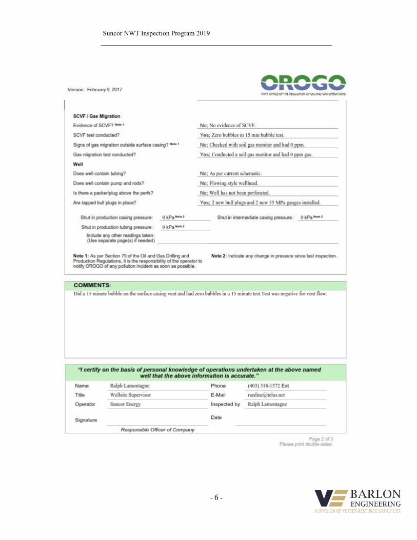
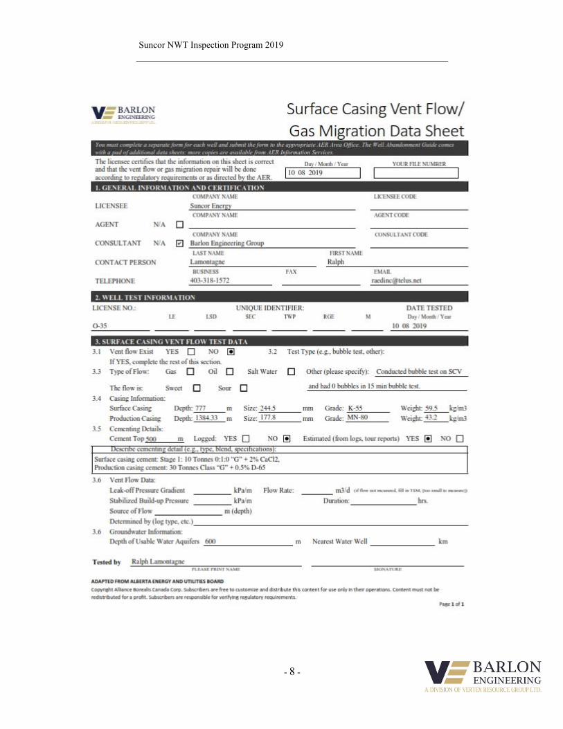
Version: February 9, 2017
Page 1 of 2 Please print double-sided
APPROVAL TO ALTER THE CONDITION OF A WELL
This form is an application for a Well Approval under Section 10 of the Oil and Gas Drilling and Production
Regulations.
INSTRUCTIONS:
1. Complete both pages.
2. Send one electronic copy of this form and supporting technical documentation by email to [email protected].
3. Send two signed hard copies of this form and supporting technical documentation by courier to:
Chief Conservation Officer Office of the Regulator of Oil and Gas Operations 4th floor Northwest Tower 5201 50th Avenue Yellowknife NT X1A 3S9
WELL INFORMATION
Well Name SUNCOR et al BELE 0-35 Operator Suncor Energy
Well Type Exploratory Well (if Other, specify _______)
Contractor
RELATED LICENCES, PERMITS, AND AUTHORIZATIONS
Operating Licence No. NWT-OL-2014-008 Operations Authorization OA-2021-003-SUN
PRA Licence No. Select Station Keeping Not Applicable
Land Structure Conventional Land
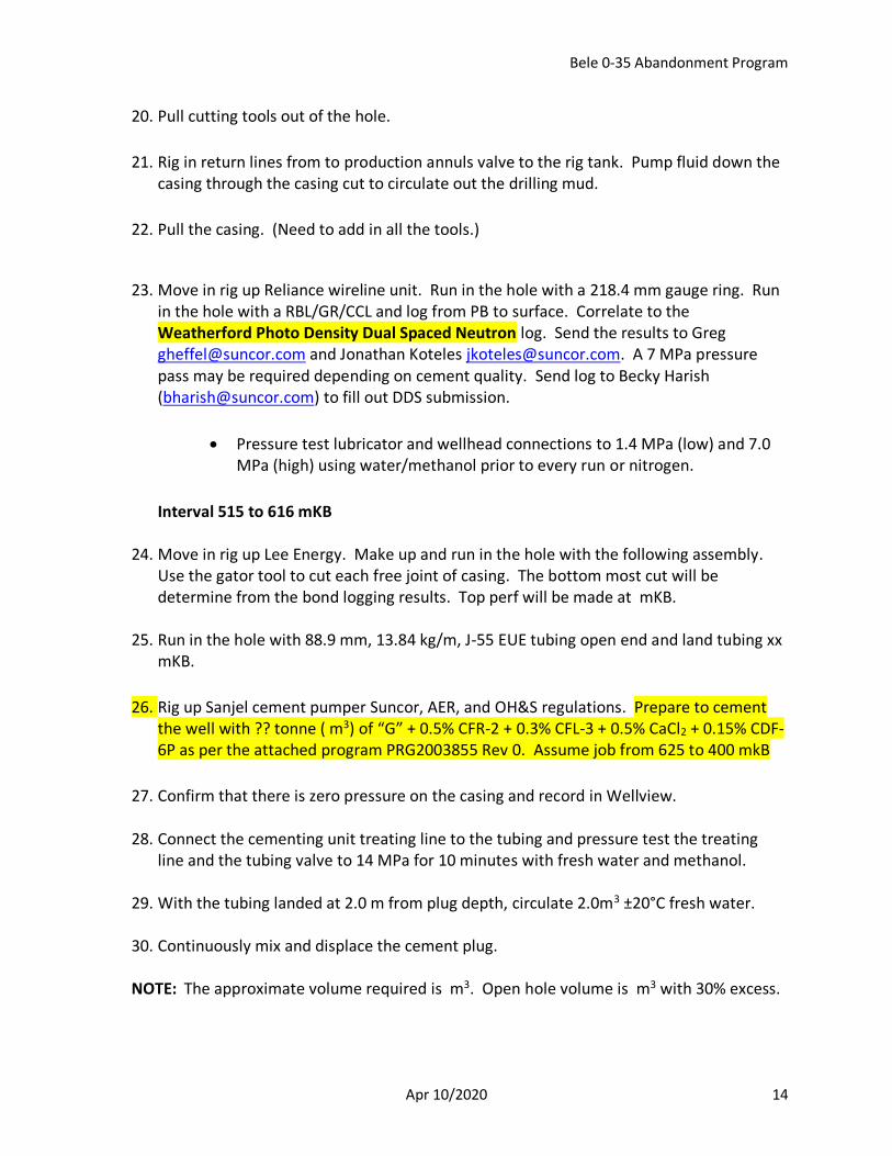
Land Use Permit No. Issued by: Select Mackenzie Valley Land and Water
Board
Water Licence No. Issued by: Select Mackenzie Valley Land and Water
Board
ACTIVITY INFORMATION
Current Well Status Standing Anticipated Well Status Abandoned
Well Path Vertical Elevation KB/RT 397.76 m
Approximate Start Date Feb 1/22 Ground Level / Seafloor 393.26 m
Est. Days on Location 15 days Anticipated Total Depth 1384 m KB
WELL OPERATION PROGRAM
Activity Type Top to Bottom Interval (m KB)
Comments
Abandonment 117-615 Squeezeing Water zones, abandon wellbore to OGDPR
Select - section 56 and OROGO Well Suspension and
Select - Abandonment Guidelines and Interpretation Notes.
Select -
Version: February 9, 2017
Page 2 of 2 Please print double-sided
Additional Information
“I certify that the information provided on this form is true and correct”
Name Greg Heffel Phone (403) 816-2422 Ext
Title Specializes Completion
Engineering
E-Mail [email protected]
Operator Suncor Energy
Signature
Date
Responsible Officer of Company
OROGO use Only ACW _________ - _______ OA _________ - _______
Bele 0-35 Abandonment Program
Apr 10/2020 1
NWT Facility SUNCOR et al BELE 0-35 Abandonment Program
Bottom Hole Location: 300O356640126150
Click here to enter text.
Project Name: IO #:
AFE Amount: $
Rev #0
Corporate Head Office
Suncor Energy Inc.
P.O. Box 2844, 150 - 6 Avenue S.W.
Calgary, Alberta
Canada T2P 3E3
T: 403-296-8000
Bele 0-35 Abandonment Program
Apr 10/2020 2
I. OBJECTIVE
The objective is to abandon the well. A bond log will be run to find the cement top on the production casing. From that information the production casing will be cut and pulled. Another bond log will be run on the surface casing to find the free pipe. Casing will be perforated to cover off the water zones. A cement plug or wells will be placed to squeeze of the water zones. The well will be turned over to logistics to be cut and capped.
II. WELL DATA
Well Name: SUNCOR et al BELE 0-35
Permit Number: N85A469 U.W.I: 300O356640126150 AFE Number: Working Interest % 100% AFE Amount: Spud Date:
$ Feb 14/86
Rig Release:
Apr 2/86
Elevations: KB: 397.76 m GL: 393.26 m CF: N/A Depths: TD: 1384.00 mKB PBTD: ?? mKB BGWP: m Directional: TVD: Vertical Angle: n/a KOP: n/a Latitude: 66° 34’ 58.1357” N Longitude: 126° 21’ 32.1083” W
III. TUBULAR & WELLHEAD DATA
Conductor: 5 jts – 339.7 mm, 101.2 kg/m, K-55, BT&C csg set @ 63.0 mKB
Cemented w/pumped 1.6 m3 of water followed by 8.3 m3 (10.8 tonne) of
G + 3.0% CaCl2 @ 1890 kg/m3 cement, float not holding.
?? m3 good cement returns to surface
Surface Casing: 3 jts – 244.5 mm, 59.53 kg/m, K-55, LT&C set @ 777.0 mKB 19 jts – 244.5 mm, 59.53 kg/m, T-95, LT&C set @ 739.03 mKB 42 jts – 244.5 mm, 59.53 kg/m, K-55, LT&C set @ 515.66 mKB
ECP & DV toolset at 37.97 mKB
Cemented w/ 1 stage 10 tonne “G” + 2.0% CaCl2 @ 1895 kg/m3 2 stage 4.4 tonne of “G” + 2.0% CaCl2 @ 1895 kg/m3. 2.0 m3 good cement returns to surface

Bele 0-35 Abandonment Program
Apr 10/2020 3
Production Casing: 117 jts – 177.8 mm, 43.16 kg/m, MN-80, LT&C csg set @ 1384.33 mKB
Cemented w/ 4.8 m3 water, lead 30.0 tonne (39.6 m3) of “G” + 0.5% D65
@ 1890 kg/m, bumped plug with 18 MPa. Bleed off float held.
Cement top calculated to be at 500 mKB. Bond log that was run on Feb
6/86 indicates cement top at approximately 676.0 mKB
0.0 m3 of cement returns to surface
Wellhead: 279.4 mm x 245 mm Casing Bowl, 21 MPa, McEvoy 279.4 mm x 179.4 mm Tubing Head, 21 MPa Cameron 179.4 mm x 65.1 mm, Tubing Head Adapter Flange, 21 MPa 65.1 mm, 35 MPa, Master Valve, Cameron 65.1 mm x 52.4 mm 21 MPa Flow Tee 52.4 mm, 21 MPa, Wing Valve
Bele 0-35 Abandonment Program
Apr 10/2020 4
IV. ATTACHMENTS
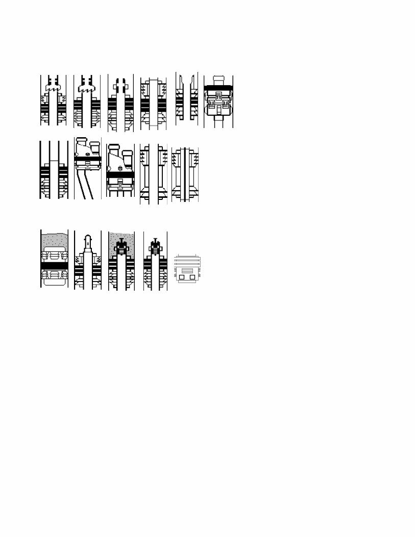
• Wellbore diagram
Well History
Feb 1986 DRILLING HISTORY
This well was spud on February 14, 1986 and drilled as follows
Conductor 1
· Drilled 445 mm conductor hole to 63 mKB with · Ran 5 joints 340 mm 101 kg/m K-55 BT&C casing
· Landed at 63.0 mKB.
· Cemented in place with 10.8 tonnes G w/ 3% CaCl2, float did not hole.
Surface Hole
· Tagged cement at 52.0 m drilled out. · Switched to air drilling at 163.0 m. · No water inflow encountered at 333.0 m
· 362 m string weight dropped to 12,000 daN. Fished BHA out. Ran in with new DC.
· Finish drilling to 777.00
· Logged (DIL-GR, CHL, LDT- MGR-Dual Caliper, BHCS, HDT-Cal) open hole to 777 mKB; casing shoe at 63 mKB
· Ran 245 mm 60 kg/m K-55 LT&C casing (see casing record attached)
· Cemented with 10 tonnes class G cement (stage 1); · Cemented with 4.4 tonnes class G + 2% CaCl2 (stage 2); stage tool at 45 mKB
· 2.0 m3 good cement returns to surface
· Weld on casing bowl (10 3000# x 9 5/8); pressure tested weld to 21 MPa.
· RIH with 216 mm bit and tagged DV closing plug at 37.97 m. · Drilled out DV tool plug then continued to drill out float with 216 mm bit.
Surface Section
Day 9 started to drill surface hole, drilled to 85 m with water based mud
Day 10 Drilled to 163 m with water/air. Switched to air at 100 m. No fluid inflow, lost
circulation problems apparent.
Bele 0-35 Abandonment Program
Apr 10/2020 5
Day 11 Drilled to 270 m with air. Twisted off at collar.
Day 12 Drilled to 333 m with air. Fished BHA. Drilling ahead and noted mist in returns.
Day 13 Drilled to 362 m with air. Twisted off again. Fished BHA again. Waiting on DC
inspections.
Day 14 Drilled to 362 m with air. Finished DC and BHA inspection.
Day 15 Drilled to 401 m with air. Changed direction of Bluie line to off lease making 12 m3/hr of
fresh water with 125 mg/L at 363 m.
Day 16 Drilled to 468 m with air.
Day 17 Drilled to 585 m with air.
Day 18 Drilled to 590 m with air.
Day 19 Drilled to 639 m with air.
Day 20 Drilled to 692 m with air.
Day 21 Drilled to 718 m with air.
Day 22 Drilled to 768 m with air.
Day 23 Drilled to 777 m with air.
Main Hole
· Displaced hole to mud.
· Cored 1330.5-1340.6, 1340.6 – 1353.0, and 34 sidewall cores
· Logged (DLL-MSFL, CNL-LDT-NGT-AMS, BHCS, HDT, MEL, SNL-LDT, WST)
· Performed DSTs over Mt Clark and Mt Cap formations
· Ran 117 joints 178 mm 43.16 kg/m MN-80 LT&C casing
· Casing landed at 1384.33 mKB
· Cemented with 30 tonnes class G with 0.5 % D65
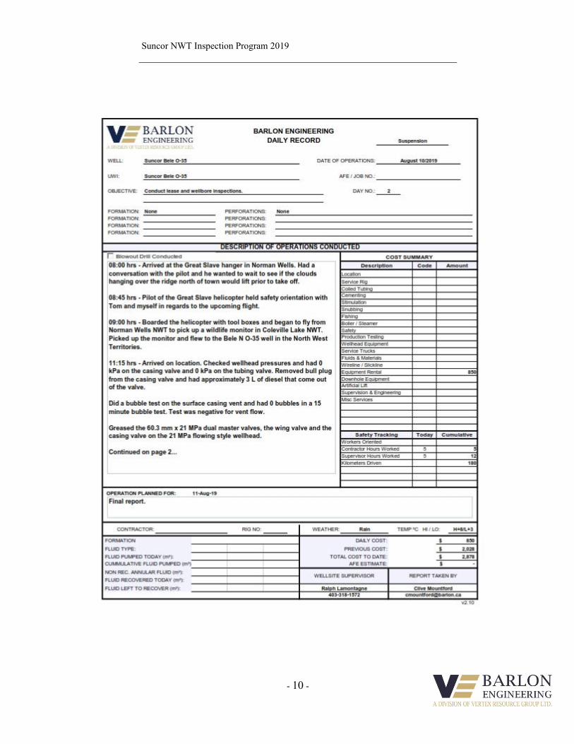
· Displaced cement with drilling mud; Bump Plug w/ 18 MPa. Sept 2009 Did a lease inspection. Flew to location. Did a bubble test on vent no issues. Serviced
the wellhead. Pressure tested the casing to 1.0 MPa for 10 minutes, good. Filled the
casing up with 200 l of Nalco R-7390 corrosion inhibitor. Rigged out.
Sept 2013 Did a lease inspection. Flew to location. Did a bubble test on vent no issues. Serviced
the wellhead. Rigged out.

Bele 0-35 Abandonment Program
Apr 10/2020 6
Aug 2019 A OROGO inspection report was done by Barlon Engineering. Did a bubble test which
was negative and did a gas migration test which was negative. Serviced the wellhead.
Bele 0-35 Abandonment Program
Apr 10/2020 7
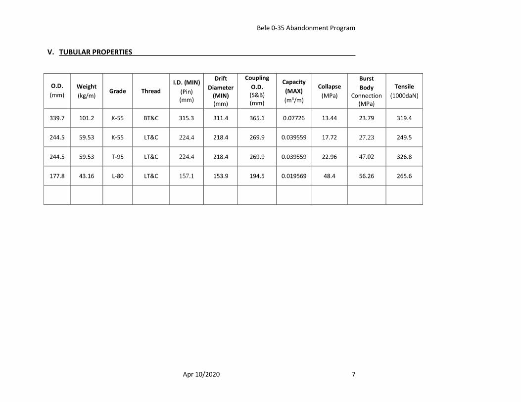
V. TUBULAR PROPERTIES
O.D.
(mm)
Weight
(kg/m) Grade Thread
I.D. (MIN)
(Pin) (mm)
Drift
Diameter (MIN) (mm)
Coupling
O.D. (S&B) (mm)
Capacity
(MAX)
(m3/m)
Collapse
(MPa)
Burst
Body Connection
(MPa)
Tensile
(1000daN)
339.7 101.2 K-55 BT&C 315.3 311.4 365.1 0.07726 13.44 23.79 319.4
244.5 59.53 K-55 LT&C 224.4 218.4 269.9 0.039559 17.72 27.23 249.5
244.5 59.53 T-95 LT&C 224.4 218.4 269.9 0.039559 22.96 47.02 326.8
177.8 43.16 L-80 LT&C 157.1 153.9 194.5 0.019569 48.4 56.26 265.6
Bele 0-35 Abandonment Program
Apr 10/2020 8
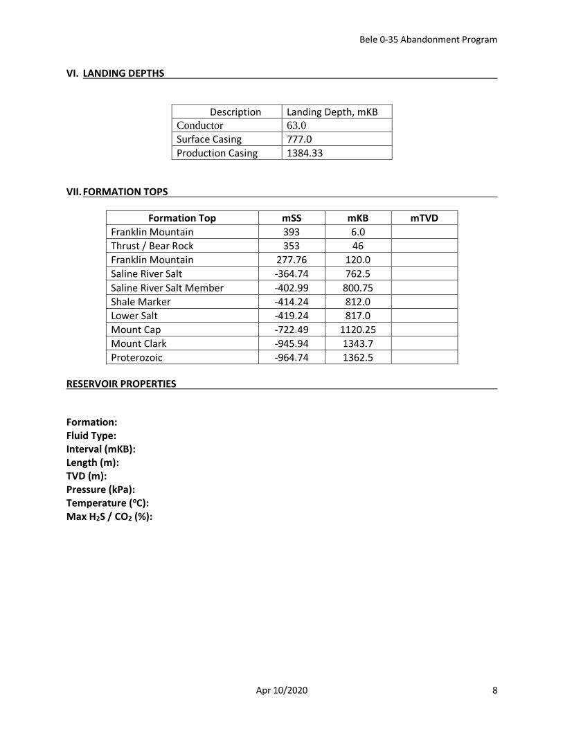
VI. LANDING DEPTHS
Description Landing Depth, mKB Conductor 63.0
Surface Casing 777.0
Production Casing 1384.33
VII. FORMATION TOPS
Formation Top mSS mKB mTVD
Franklin Mountain 393 6.0
Thrust / Bear Rock 353 46
Franklin Mountain 277.76 120.0
Saline River Salt -364.74 762.5
Saline River Salt Member -402.99 800.75
Shale Marker -414.24 812.0
Lower Salt -419.24 817.0
Mount Cap -722.49 1120.25
Mount Clark -945.94 1343.7
Proterozoic -964.74 1362.5
RESERVOIR PROPERTIES
Formation: Fluid Type: Interval (mKB): Length (m): TVD (m): Pressure (kPa): Temperature (oC): Max H2S / CO2 (%):
Bele 0-35 Abandonment Program
Apr 10/2020 9
VIII. SUNCOR REQUIREMENTS General: This well is part of a project which is proprietary to Suncor Energy Inc., Information is to be held strictly confidential, document not to be copied. Well site Supervisors must ensure that the applicable Suncor Safe Work Practices are observed, including the following:
• Safety Orientation - All Onsite personnel must be oriented to site hazards and signed in on the sign-in log.
• All personnel performing work must have a valid Completions Work Permit prior to commencing work.
• Ground Disturbance deeper than 30 cm (including rig anchors) is not to be carried out without the direction of a Logistics representative.
• Hydrocarbon Exposure LEL monitors will be used by all personnel on any job where hydrocarbon vapors may be present.
• H2S Safe Work Practice will be observed by providing H2S detection equipment, trained personnel, and specified safety equipment when required.
• Ensure a Field Level Hazard Assessments (FLHA) to identify and document site specific hazards are completed prior to commencing work, before all critical tasks and at any change in scope during the task as per the Suncor Completions SWP.
• Directive 33 Well Servicing and Completions Operations—Requirement Regarding the Potential for Explosive Mixtures and Ignition in Wells – have documented practices available at the well site for the safe management of the potential for explosive mixtures and ignition in wells and associated surface equipment. A Fire and Explosion Hazard Management Plan is to be posted at the work site.
Ensure current MSDS sheets are onsite for all controlled products including produced fluids. Ensure that workers are made aware or the Hazards and safeguards. All unplanned events that occur that cause or could have caused loss are to be reported to the Completions Superintendent immediately. Incidents with or without loss must reports must be utilized as directed by the Completions Superintendent. All wastes must be manifested and tracked when leaving the facility, to a non-Suncor owned disposal site, as per AER Directive 58. A fully completed AER Alberta Environment Waste Manifest is to be submitted with the final report for all Dangerous Oilfield Wastes (DOWs). Conduct all operations in accordance with applicable IRP’s, provincial acts and regulations pertaining to the AER.

Bele 0-35 Abandonment Program
Apr 10/2020 10
Ensure a copy of the Suncor Corporate ERP is available on site. Complete and post the Suncor Completions Site Specific ERP. An Assignment of Supervisor form must be completed and posted at location. An injured worker transportation form must be posted on location. If the work site is greater than 40 minutes from an approved medical facility an alternate form of injured worker transportation with qualified emergency medical personnel must be present on location. Note: Suncor medic clinics qualify as an approved medical facility. All employees and contractors certification of First Aid, H2S, WHMIS and TDG etc. must be verified before they are allowed access to work on site. All contractors’ competency must be verified before they are allowed access to work onsite. Frequent, task-specific, on-going competency assessments must also be conducted for the duration of a contractor’s term in a specific position. A site walk inspection must be conducted every day in conjunction with a morning operational / safety meeting outlining all safety hazards and planned procedures for the day. This must be recorded on the daily tour report. Road use and pipeline crossing agreements and Temporary Diversion Licenses, when required, must be in place prior to commencing any operations. Any operation outlined in this program or otherwise implied by the nature of the work to be conducted that requires clarification shall be discussed with Operations. Calgary office, Completions Analyst, [email protected] will submit required AER DDS notifications.
Bele 0-35 Abandonment Program
Apr 10/2020 11
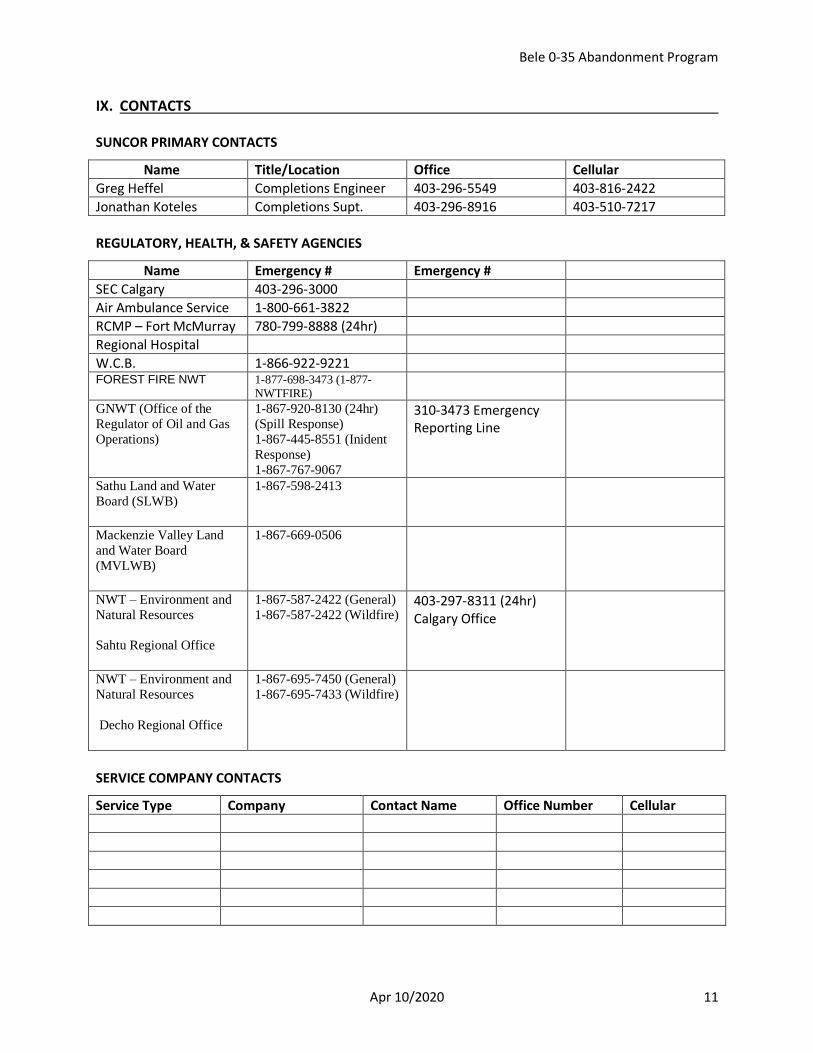
IX. CONTACTS SUNCOR PRIMARY CONTACTS
Name Title/Location Office Cellular
Greg Heffel Completions Engineer 403-296-5549 403-816-2422
Jonathan Koteles Completions Supt. 403-296-8916 403-510-7217
REGULATORY, HEALTH, & SAFETY AGENCIES
Name Emergency # Emergency #
SEC Calgary 403-296-3000
Air Ambulance Service 1-800-661-3822
RCMP – Fort McMurray 780-799-8888 (24hr)
Regional Hospital
W.C.B. 1-866-922-9221 FOREST FIRE NWT 1-877-698-3473 (1-877-
NWTFIRE)
GNWT (Office of the
Regulator of Oil and Gas
Operations)
1-867-920-8130 (24hr)
(Spill Response)
1-867-445-8551 (Inident
Response)
1-867-767-9067
310-3473 Emergency Reporting Line
Sathu Land and Water
Board (SLWB)
1-867-598-2413
Mackenzie Valley Land
and Water Board
(MVLWB)
1-867-669-0506
NWT – Environment and
Natural Resources
Sahtu Regional Office
1-867-587-2422 (General)
1-867-587-2422 (Wildfire)
403-297-8311 (24hr) Calgary Office
NWT – Environment and
Natural Resources
Decho Regional Office
1-867-695-7450 (General)
1-867-695-7433 (Wildfire)
SERVICE COMPANY CONTACTS
Service Type Company Contact Name Office Number Cellular
Bele 0-35 Abandonment Program
Apr 10/2020 12
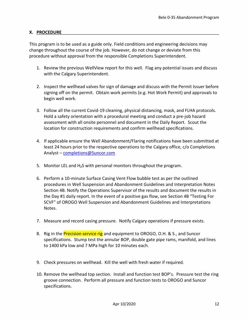
X. PROCEDURE This program is to be used as a guide only. Field conditions and engineering decisions may change throughout the course of the job. However, do not change or deviate from this procedure without approval from the responsible Completions Superintendent.
1. Review the previous WellView report for this well. Flag any potential issues and discuss with the Calgary Superintendent.
2. Inspect the wellhead valves for sign of damage and discuss with the Permit Issuer before signing off on the permit. Obtain work permits (e.g. Hot Work Permit) and approvals to begin well work.
3. Follow all the current Covid-19 cleaning, physical distancing, mask, and FLHA protocols. Hold a safety orientation with a procedural meeting and conduct a pre-job hazard assessment with all onsite personnel and document in the Daily Report. Scout the location for construction requirements and confirm wellhead specifications.
4. If applicable ensure the Well Abandonment/Flaring notifications have been submitted at least 24 hours prior to the respective operations to the Calgary office, c/o Completions Analyst – [email protected]
5. Monitor LEL and H₂S with personal monitors throughout the program.
6. Perform a 10-minute Surface Casing Vent Flow bubble test as per the outlined procedures in Well Suspension and Abandonment Guidelines and Interpretation Notes Section 4B. Notify the Operations Supervisor of the results and document the results in the Day #1 daily report. In the event of a positive gas flow, see Section 4B “Testing For SCVF” of OROGO Well Suspension and Abandonment Guidelines and Interpretations Notes.
7. Measure and record casing pressure. Notify Calgary operations if pressure exists.
8. Rig in the Precision service rig and equipment to OROGO, O.H. & S., and Suncor specifications. Stump test the annular BOP, double gate pipe rams, manifold, and lines to 1400 kPa low and 7 MPa high for 10 minutes each.
9. Check pressures on wellhead. Kill the well with fresh water if required.
10. Remove the wellhead top section. Install and function test BOP’s. Pressure test the ring groove connection. Perform all pressure and function tests to OROGO and Suncor specifications.
Bele 0-35 Abandonment Program
Apr 10/2020 13
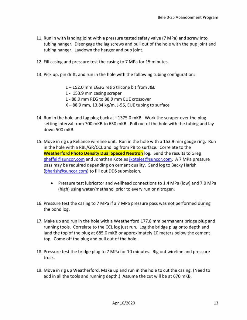
11. Run in with landing joint with a pressure tested safety valve (7 MPa) and screw into
tubing hanger. Disengage the lag screws and pull out of the hole with the pup joint and tubing hanger. Laydown the hanger and pup joint.
12. Fill casing and pressure test the casing to 7 MPa for 15 minutes.
13. Pick up, pin drift, and run in the hole with the following tubing configuration:
1 – 152.0 mm EG3G retip tricone bit from J&L 1 - 153.9 mm casing scraper 1 - 88.9 mm REG to 88.9 mm EUE crossover X – 88.9 mm, 13.84 kg/m, J-55, EUE tubing to surface
14. Run in the hole and tag plug back at ~1375.0 mKB. Work the scraper over the plug setting interval from 700 mKB to 650 mKB. Pull out of the hole with the tubing and lay down 500 mKB.
15. Move in rig up Reliance wireline unit. Run in the hole with a 153.9 mm gauge ring. Run in the hole with a RBL/GR/CCL and log from PB to surface. Correlate to the Weatherford Photo Density Dual Spaced Neutron log. Send the results to Greg [email protected] and Jonathan Koteles [email protected]. A 7 MPa pressure pass may be required depending on cement quality. Send log to Becky Harish ([email protected]) to fill out DDS submission.
• Pressure test lubricator and wellhead connections to 1.4 MPa (low) and 7.0 MPa (high) using water/methanol prior to every run or nitrogen.
16. Pressure test the casing to 7 MPa if a 7 MPa pressure pass was not performed during the bond log.
17. Make up and run in the hole with a Weatherford 177.8 mm permanent bridge plug and running tools. Correlate to the CCL log just run. Log the bridge plug onto depth and land the top of the plug at 685.0 mKB or approximately 10 meters below the cement top. Come off the plug and pull out of the hole.
18. Pressure test the bridge plug to 7 MPa for 10 minutes. Rig out wireline and pressure truck.
19. Move in rig up Weatherford. Make up and run in the hole to cut the casing. (Need to add in all the tools and running depth.) Assume the cut will be at 670 mKB.
Bele 0-35 Abandonment Program
Apr 10/2020 14
20. Pull cutting tools out of the hole.
21. Rig in return lines from to production annuls valve to the rig tank. Pump fluid down the casing through the casing cut to circulate out the drilling mud.
22. Pull the casing. (Need to add in all the tools.)
23. Move in rig up Reliance wireline unit. Run in the hole with a 218.4 mm gauge ring. Run in the hole with a RBL/GR/CCL and log from PB to surface. Correlate to the Weatherford Photo Density Dual Spaced Neutron log. Send the results to Greg [email protected] and Jonathan Koteles [email protected]. A 7 MPa pressure pass may be required depending on cement quality. Send log to Becky Harish ([email protected]) to fill out DDS submission.
• Pressure test lubricator and wellhead connections to 1.4 MPa (low) and 7.0 MPa (high) using water/methanol prior to every run or nitrogen.
Interval 515 to 616 mKB
24. Move in rig up Lee Energy. Make up and run in the hole with the following assembly. Use the gator tool to cut each free joint of casing. The bottom most cut will be determine from the bond logging results. Top perf will be made at mKB.
25. Run in the hole with 88.9 mm, 13.84 kg/m, J-55 EUE tubing open end and land tubing xx mKB.
26. Rig up Sanjel cement pumper Suncor, AER, and OH&S regulations. Prepare to cement the well with ?? tonne ( m3) of “G” + 0.5% CFR-2 + 0.3% CFL-3 + 0.5% CaCl2 + 0.15% CDF-6P as per the attached program PRG2003855 Rev 0. Assume job from 625 to 400 mkB
27. Confirm that there is zero pressure on the casing and record in Wellview.
28. Connect the cementing unit treating line to the tubing and pressure test the treating line and the tubing valve to 14 MPa for 10 minutes with fresh water and methanol.
29. With the tubing landed at 2.0 m from plug depth, circulate 2.0m3 ±20°C fresh water.
30. Continuously mix and displace the cement plug.
NOTE: The approximate volume required is m3. Open hole volume is m3 with 30% excess.
Bele 0-35 Abandonment Program
Apr 10/2020 15
NOTE: At 200 L/min it will take approximately 100 minutes to circulate the cement in. Well may go on vacuum. Allow the cement plug to find its balance.
NOTE: Have Sanjel provide 2 cement samples at surface to monitor on location. Ensure they are kept in the heated environment and monitor that the samples gel and set up in a reasonable time.
31. Once the plug has been placed for the full length of the plug weight, which should bring
the plug top to 400 mKB. Pull the tubing up to 380 mKB and wash out the tubing with 1.5x tubing volume ±20°C fresh water. If unable to gain circulation during cementing operations do not attempt to back wash, continue with pulling and standing tubing.
32. Next day Run in the hole and tag for the cement top. Report results to Calgary.
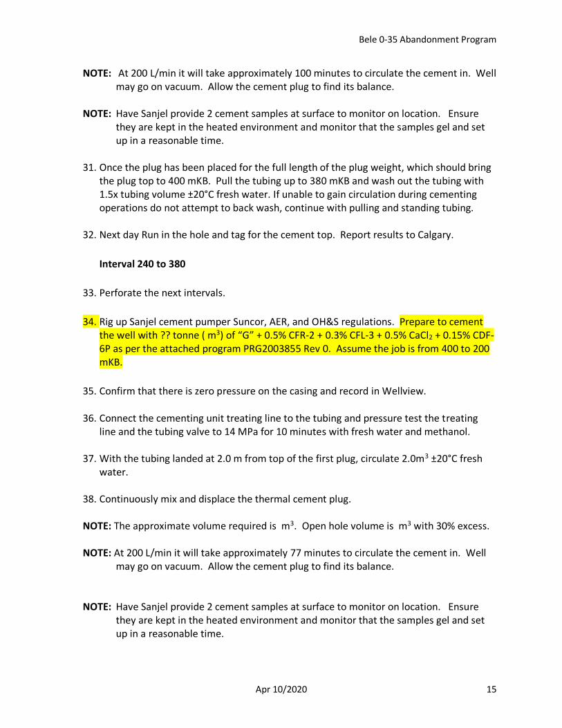
Interval 240 to 380
33. Perforate the next intervals.
34. Rig up Sanjel cement pumper Suncor, AER, and OH&S regulations. Prepare to cement the well with ?? tonne ( m3) of “G” + 0.5% CFR-2 + 0.3% CFL-3 + 0.5% CaCl2 + 0.15% CDF-6P as per the attached program PRG2003855 Rev 0. Assume the job is from 400 to 200 mKB.
35. Confirm that there is zero pressure on the casing and record in Wellview.
36. Connect the cementing unit treating line to the tubing and pressure test the treating line and the tubing valve to 14 MPa for 10 minutes with fresh water and methanol.
37. With the tubing landed at 2.0 m from top of the first plug, circulate 2.0m3 ±20°C fresh water.
38. Continuously mix and displace the thermal cement plug.
NOTE: The approximate volume required is m3. Open hole volume is m3 with 30% excess.
NOTE: At 200 L/min it will take approximately 77 minutes to circulate the cement in. Well
may go on vacuum. Allow the cement plug to find its balance.
NOTE: Have Sanjel provide 2 cement samples at surface to monitor on location. Ensure
they are kept in the heated environment and monitor that the samples gel and set up in a reasonable time.
Bele 0-35 Abandonment Program
Apr 10/2020 16
39. Once the plug has been placed for the full length of the plug weight, which should bring the plug top to 200 mKB, rig out cement equipment. Pull the tubing up to 180 mKB and wash out the tubing with 1.5x tubing volume ±20°C fresh water. If unable to gain circulation do not attempt to back wash just proceed with pulling tubing.
40. Next day run in the hole and tag for the cement top. Report results to Calgary. Pull out of the hole.
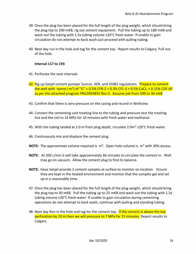
Interval 117 to 193
41. Perforate the next intervals
42. Rig up Sanjel cement pumper Suncor, AER, and OH&S regulations. Prepare to cement the well with tonne ( m3) of “G” + 0.5% CFR-2 + 0.3% CFL-3 + 0.5% CaCl2 + 0.15% CDF-6P as per the attached program PRG2003855 Rev 0. Assume job from 200 to 30 mkB
43. Confirm that there is zero pressure on the casing and record in Wellview.
44. Connect the cementing unit treating line to the tubing and pressure test the treating line and the coil to 14 MPa for 10 minutes with fresh water and methanol.
45. With the tubing landed at 2.0 m from plug depth, circulate 2.0m3 ±20°C fresh water.
46. Continuously mix and displace the cement plug.
NOTE: The approximate volume required is m3. Open hole volume is m3 with 30% excess.
NOTE: At 200 L/min it will take approximately 66 minutes to circulate the cement in. Well
may go on vacuum. Allow the cement plug to find its balance. NOTE: Have Sanjel provide 2 cement samples at surface to monitor on location. Ensure
they are kept in the heated environment and monitor that the samples gel and set up in a reasonable time.
47. Once the plug has been placed for the full length of the plug weight, which should bring
the plug top to 30 mKB. Pull the tubing up to 25 mKB and wash out the tubing with 1.5x tubing volume ±20°C fresh water. If unable to gain circulation during cementing operations do not attempt to back wash, continue with pulling and standing tubing.
48. Next day Run in the hole and tag for the cement top. If the cement is above the top perforation by 10 m then we will pressure to 7 MPa for 15 minutes. Report results to Calgary.
Bele 0-35 Abandonment Program
Apr 10/2020 17
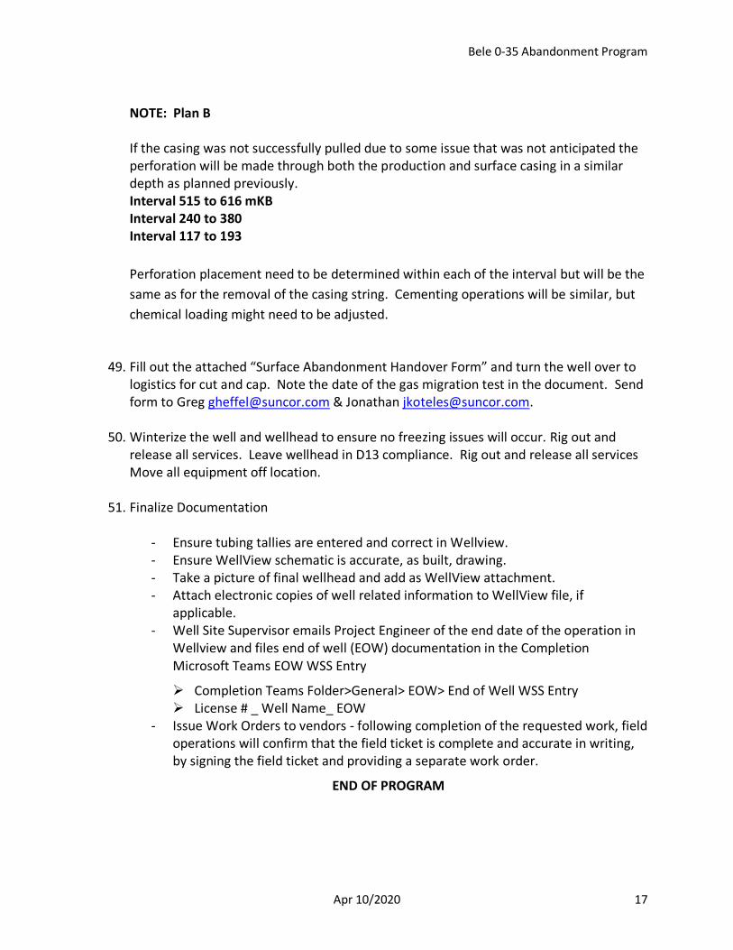
NOTE: Plan B If the casing was not successfully pulled due to some issue that was not anticipated the perforation will be made through both the production and surface casing in a similar depth as planned previously. Interval 515 to 616 mKB Interval 240 to 380 Interval 117 to 193
Perforation placement need to be determined within each of the interval but will be the
same as for the removal of the casing string. Cementing operations will be similar, but
chemical loading might need to be adjusted.
49. Fill out the attached “Surface Abandonment Handover Form” and turn the well over to logistics for cut and cap. Note the date of the gas migration test in the document. Send form to Greg [email protected] & Jonathan [email protected].
50. Winterize the well and wellhead to ensure no freezing issues will occur. Rig out and release all services. Leave wellhead in D13 compliance. Rig out and release all services Move all equipment off location.
51. Finalize Documentation
- Ensure tubing tallies are entered and correct in Wellview. - Ensure WellView schematic is accurate, as built, drawing. - Take a picture of final wellhead and add as WellView attachment. - Attach electronic copies of well related information to WellView file, if
applicable. - Well Site Supervisor emails Project Engineer of the end date of the operation in
Wellview and files end of well (EOW) documentation in the Completion Microsoft Teams EOW WSS Entry
➢ Completion Teams Folder>General> EOW> End of Well WSS Entry ➢ License # _ Well Name_ EOW
- Issue Work Orders to vendors - following completion of the requested work, field operations will confirm that the field ticket is complete and accurate in writing, by signing the field ticket and providing a separate work order.
END OF PROGRAM
Bele 0-35 Abandonment Program
Apr 10/2020 18
XI. PROGRAM SIGN OFF
PREPARED BY:
Greg Heffel Engineer, Completions Eng
Date
APPROVED BY: Tier 1:
Jonathan Koteles Superintendent, Completions
Date
APPROVED BY: Tier 1:
Dean Tymko Director, Completions
Date

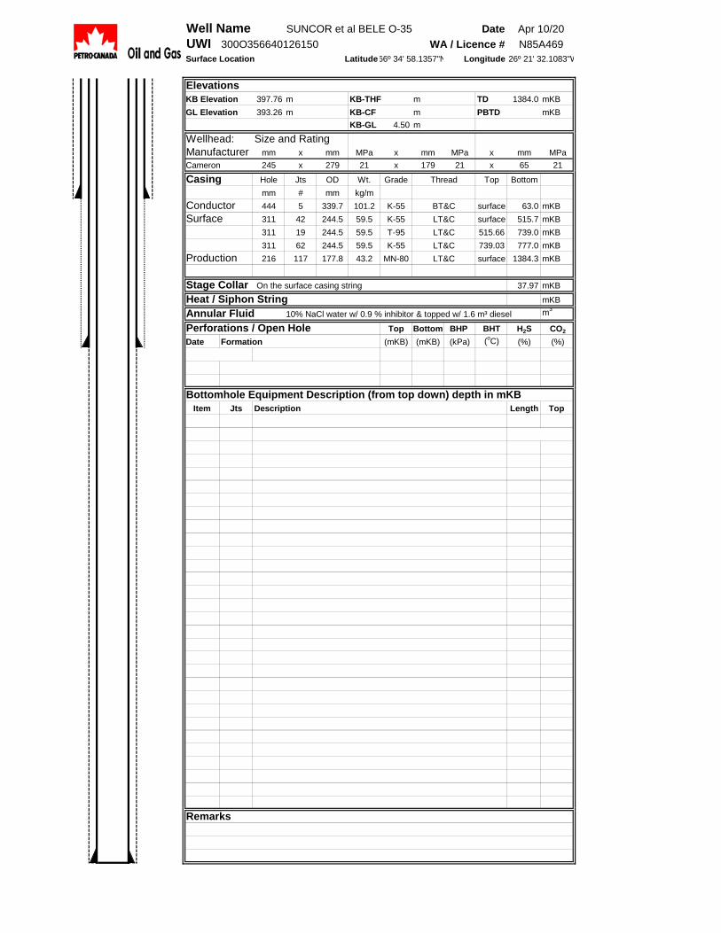
Well Name SUNCOR et al BELE O-35 Date
UWI 300O356640126150 WA / Licence #
Surface Location Latitude Longitude
Elevations
KB Elevation 397.76 m KB-THF m TD 1384.0 mKB
GL Elevation 393.26 m KB-CF m PBTD mKB
KB-GL 4.50 m
Wellhead: Size and Rating
Manufacturer mm x mm MPa x mm MPa x mm MPa
Cameron 245 x 279 21 x 179 21 x 65 21
Casing Hole Jts OD Wt. Grade Top Bottom
mm # mm kg/m
Conductor 444 5 339.7 101.2 K-55 surface 63.0 mKB
Surface 311 42 244.5 59.5 K-55 surface 515.7 mKB
311 19 244.5 59.5 T-95 515.66 739.0 mKB
311 62 244.5 59.5 K-55 739.03 777.0 mKB
Production 216 117 177.8 43.2 MN-80 surface 1384.3 mKB
Stage Collar On the surface casing string 37.97 mKB
Heat / Siphon String mKB
Annular Fluid 10% NaCl water w/ 0.9 % inhibitor & topped w/ 1.6 m³ diesel m3
Perforations / Open Hole Top Bottom BHP BHT H2S CO2
Date Formation (mKB) (mKB) (kPa) (oC) (%) (%)
Bottomhole Equipment Description (from top down) depth in mKB
Item Jts Description Length Top
Remarks
26º 21' 32.1083"W66º 34' 58.1357"N
Apr 10/20
N85A469
Thread
BT&C
LT&C
LT&C
LT&C
LT&C
Prepared by: _______________________
Clive Mountford, P. Eng.
The Barlon Engineering Group Ltd.
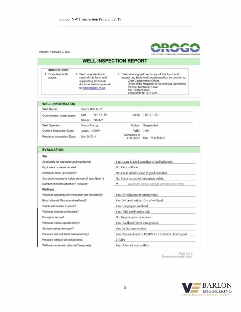
SUNCOR ENERGY INSPECTION REPORT AUGUST 2019
SUNCOR BELE O-35
Suncor NWT Inspection Program 2019
- 1 -
Table of Contents
1. Well Data ................................................................................................................................... 2
2. Schematic ................................................................................................................................... 4
3. OROGO Inspection Form ........................................................................................................ 5
4. Vent Flow Test Report.............................................................................................................. 8
5. Gas Migration Test Report ...................................................................................................... 9
6. Daily Reports ........................................................................................................................... 10
7. Pictures..................................................................................................................................... 15

Suncor NWT Inspection Program 2019
- 2 -
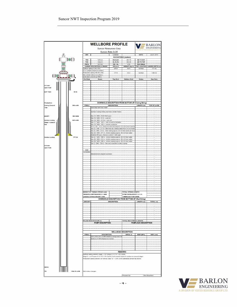
Suncor Bele O-35 Well Information
Elevations: KB: 397.76 m KB – GL: 4.50 m
GL: 393.26 m
PBTD: 1371.23 mKB MD
TD: 1384.33 mKB MD
Surface Casing: 244.5 mm, 59.5 kg/m, K-55, LT&C landed at 777.0 mKB MD
311 mm hole size
Stage 1: 10 Tonnes 0:1:0 “G” + 2% CaCl2, Stage 2 – 4.4 Tonnes 0:1:0
“G” + 2% CaCl2 (2 m3 cement returns to surface on second stage)
Production Casing: 177.8 mm, 43.15 kg/m, MN-80, LT&C landed at 1384.33 mKB MD
216 mm hole size
30 Tonnes Class “G” + 0.5% D-65 (estimated cement top 500m)
Perforations: None
Wellhead: 245 mm x 279.4 mm 21 MPa McEvoy casing bowl c/w McEvoy 21 MPa
flowing top section (see attached schematic)
Base of Groundwater
Protection: 600 mKB
Suncor NWT Inspection Program 2019
- 3 -
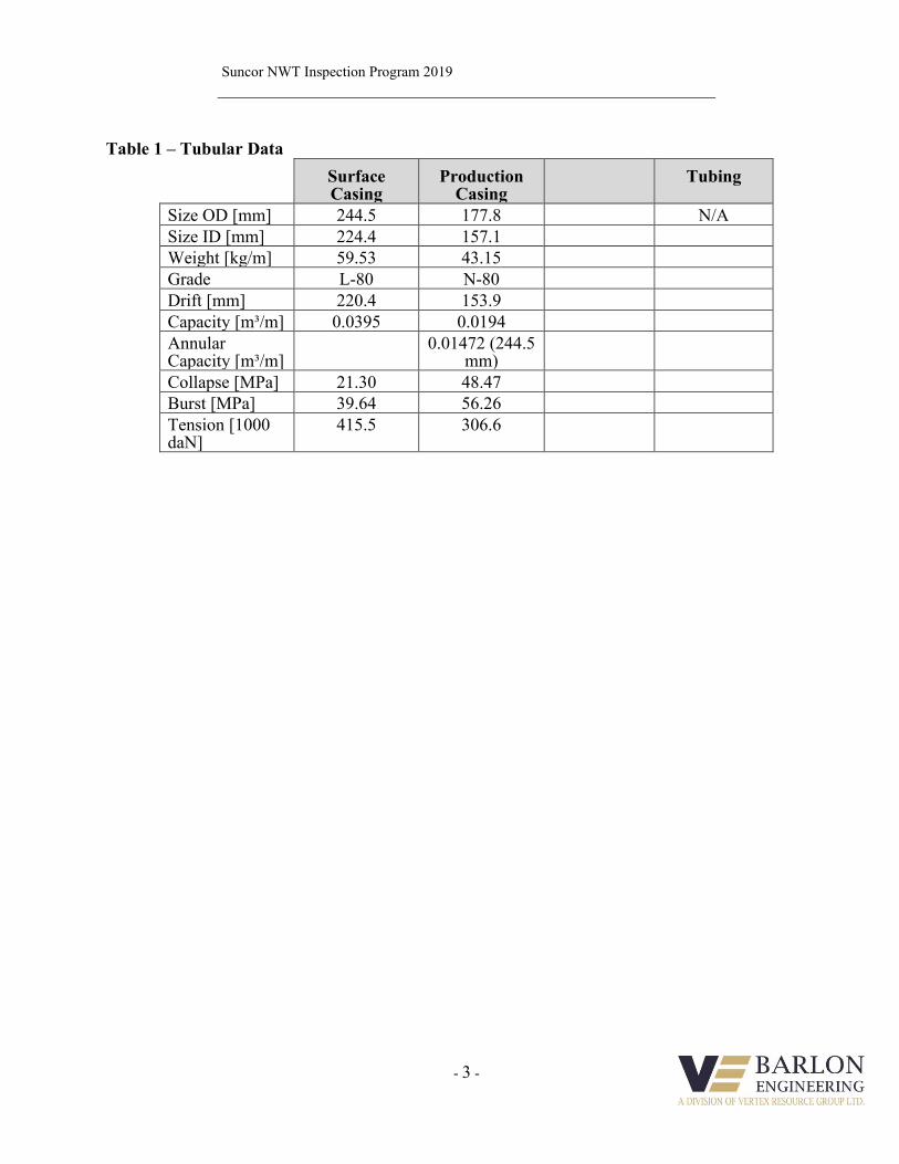
Table 1 – Tubular Data
Surface Casing
Production Casing
Tubing
Size OD [mm] 244.5 177.8 N/A
Size ID [mm] 224.4 157.1
Weight [kg/m] 59.53 43.15
Grade L-80 N-80
Drift [mm] 220.4 153.9
Capacity [m³/m] 0.0395 0.0194
Annular Capacity [m³/m]
0.01472 (244.5 mm)
Collapse [MPa] 21.30 48.47
Burst [MPa] 39.64 56.26
Tension [1000 daN]
415.5 306.6
Suncor NWT Inspection Program 2019
- 4 -
Suncor NWT Inspection Program 2019
- 5 -
Suncor NWT Inspection Program 2019
- 6 -
Suncor NWT Inspection Program 2019
- 7 -
Suncor NWT Inspection Program 2019
- 8 -

Suncor NWT Inspection Program 2019
- 9 -
Suncor NWT Inspection Program 2019
- 10 -
Suncor NWT Inspection Program 2019
- 11 -
Suncor NWT Inspection Program 2019
- 12 -
Suncor NWT Inspection Program 2019
- 13 -
Lease Picture

Suncor NWT Inspection Program 2019
- 14 -
Seal Test
Suncor NWT Inspection Program 2019
- 15 -
Completed Inspection #1
Suncor NWT Inspection Program 2019
- 16 -
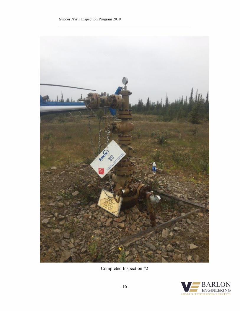
Completed Inspection #2
Suncor NWT Inspection Program 2019
- 17 -
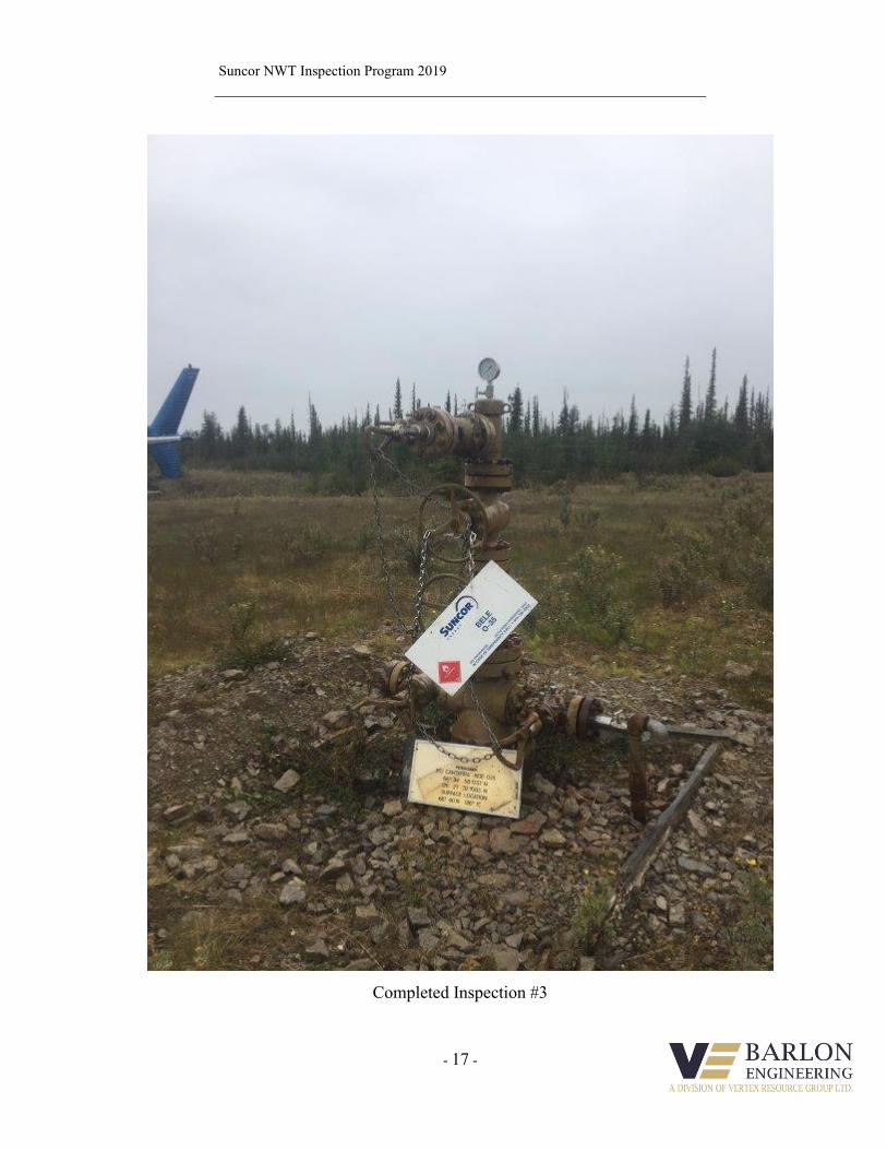
Completed Inspection #3

Suncor NWT Inspection Program 2019
- 18 -
Aerial View of Lease
Suncor NWT Inspection Program 2019
- 19 -
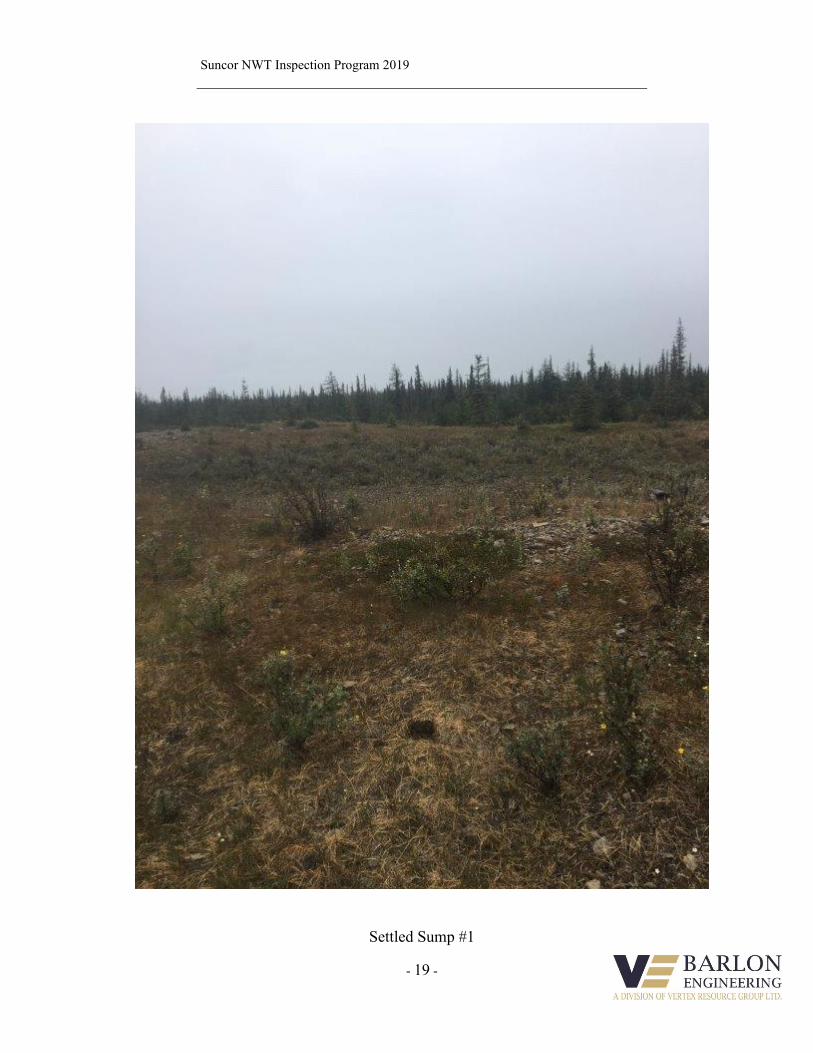
Settled Sump #1
Suncor NWT Inspection Program 2019
- 20 -
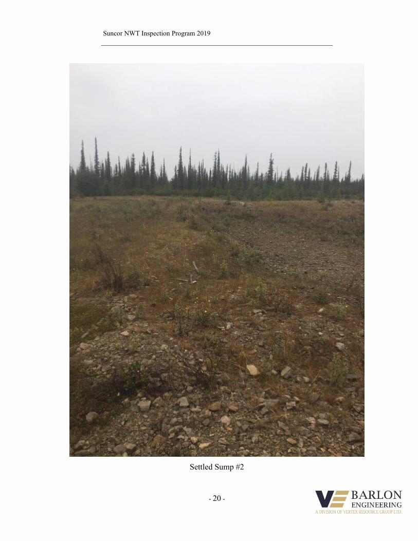
Settled Sump #2
Suncor NWT Inspection Program 2019
- 21 -
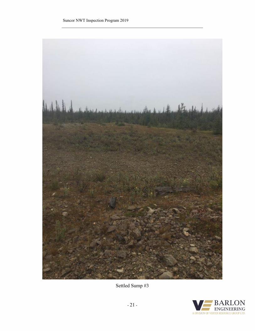
Settled Sump #3
Well Schematic
Dill 444mm surface hole @ 63mRun 339.7mm CasingCement Returns to Surface
Drill w\ water csng shoe@ 63m - 99.4m WaterAir drill 311 hole @ 99.4mto 401 m
Ream underguage holefrom 228 - 270m
Twist off DC's @ 362mWATER FLOW @ 363.0mRate @ 16 m3/hr: Na 125 mg/lNaCl = 365 mg/l (Fresh)
Foam drill 311 hole @ 401mto Inter TD @ 777m
Spot 25 gals of alcohol@ 458m
Cement top on Surf Csng@ 625 mKB (311 mm HS)
Cement top on Prod Csng@ 676 mKB
WATER FLOW @ 686.0mRate 48 m3/hrNaCl = 390 mg/l (Fresh)
Drill 311mm inter hole @ 777mSurface Csng 244.5mmlanded @ 777.0 mKBWater drill 216 mm holeSalt-Saturated mud 790 - FTD
COMMENTS
CA
NS
TR
AT
.LITH
_1
DEPTHMETRES
1 : 1000
117.8
SQU-731.2
149.0
169.5
SQU-623.5
193.0
240.9
SQU-529.1
270.0
315.9
SQU-416.0
331.9
365.9
SQU-314.1
380.0
515.6
SQU-212.4
528.0
600.0
SQU-116.0
616.0
50.0M
t Kindle
70.0
120.0F
ranklin Mtn
140.4
260.4F
ranklin Mtn Lr
502.1
762.5Saline R
iver Fm
38.3F
ormation T
ops
LLD_1OHMM0.2 2000
LLS_1OHMM0.2 2000
SFL_1OHMM0.2 2000
ILM_1OHMM0.2 2000
ILD_1OHMM0.2 2000
NPHI_1V/V0.45 -0.15
POL_10.45 -0.15
DEN_1K/M31950 2950
PEF_1B/E0 10
DRHO_1K/M3-250 250
DT_1US/M500 100
VSH_1V/V0 1
PHIT_1V/V0.4 0