approaches to prevent outboard motors from flipping … · approaches to prevent outboard motors...
TRANSCRIPT

Page 1!
Approaches to Prevent Outboard Motors From Flipping Into Boats After
Striking Floating or Submerged Objects
by Gary Polson P.E.
PropellerSafety.com
Originally Published December 18, 2013
Version: December 27, 2014
A web page has been setup to support this paper. Please check it for updates and additional materials.
This paper is for informational purposes only. It is not professional advice for those considering modifying any boat(s) or marine drive(s) with any safety devices.
© 2014 Polson Enterprises. All Rights Reserved.

Introduction
Our list of outboard motors striking submerged objects and flipping into boats continues to grow. To help prevent similar future accidents, we encourage marine drive manufacturers, boat builders, boat dealers, and entrepreneurs to consider this list of proposed solutions and to employ them and others as they see fit. We are not claiming all these approaches work, or are practical. We list them to stimulate discussion, increase awareness of the problem, inspire more solutions, and to encourage action.
Among floating and submerged objects struck by outboard motors are:
1. Wood (submerged stands of trees, floating trees, submerged stumps, floating logs, human made wooden structures)
2. Rocks, underwater outcroppings, very small islands3. Concrete pilings / piers, dykes, low water dams, retaining walls, sea walls, old salt
water barriers4. Submerged bridges, sunken vessels5. Dredge pipes6. Flood debris (floating and submerged)7. Reefs8. Sand bars9. Unknown objects
When impacted at speed, high density fixed objects and large floating objects of a density near that of wood impart tremendous amounts of energy to the outboard motor. Marine drive manufactures use log strike systems to allow the drive to swing up over the object and settle back down to the original depth after the collision. Large outboards typically use hydraulic relief valves to limit flow from the rod end of the tilt cylinder during a strike to retard the upward swing of the drive. We previously covered log strike systems and their testing in a two part post.
Its time to reevaluate the use of traditional log strike systems on some vessels. Outboard motors are increasing in horsepower, becoming heavier, and faster. Recreational boats are becoming bigger, heavier, and faster. The use of twin, triple, and even quad outboards is on the increase. High horsepower fishing boats powered by large outboards compete in fishing tournaments where speed is of the essence. These trends result in higher impact energies. Large outboards are flipping into boats under power (propeller turning at several thousand RPM due to being in the air) causing serious injuries and death.
Boating has become more widespread and the human presence has resulted in more items in and under the water (more debris, more submerged piers, more lakes formed with stumps or trees left standing, more dredging resulting in more dredge pipes, and intense storms are washing more wooden debris into reservoirs).
Page 2!

Swings in lake levels due to drought or allowing the water downstream for other uses are bringing previously unknown hazards near the surface.
As a result of these events and others, several solutions have been proposed:
1. Frangible / Break Away Drives
2. Increase Time of Contact to Reduce Peak Loads
3. Tie the Outboard to the Transom
4. Jack Plates and Lift Plates
5. Tilt Cylinder Provides Two Stage Damping
6. Increase Capacity of Existing Log Strike System
7. Active Control
8. Stops at Top of the Swing
9. Swim Platforms
10.Outboard Brackets
11. Mechanical Fences, Engine Crash Bars, Tow Bars, Roll Over Bars, & Poling Platforms
12. Reduce the Weight of Outboard Motors
13. Outboard Shallow Drives, Mud Drives and Surface Drives
14. Replace Some Outboard Motors With Alternative Drives
15. Alternative Swivel Bracket Designs
Two Related Topics
A. Utilize the Fracture Mechanics of Wood
B. Slowing / Killing the Engine
This paper will briefly examine these proposed solutions and related topics.
Page 3!

1. Frangible / Break Away Technologies
Several approaches resurfaced with Brunswick’s through hull drive (Zeus), ZF’s pod drive, and Volvo Penta’s forward facing through hull drive (IPS). These drives for larger vessels needed some way to dissipate energy from submerged object collisions other than allowing the drive to be torn off, resulting in a gaping hole in the hull, and the possibility of sinking.
Figure 1: Brunswick’s Zeus drive
Among Brunswick, Volvo, and ZF patents in this field are:
US Patent 6,315,623 Volvo Penta controlled separationUS Patent 7,435,147 Brunswick break away skeg for a marine propulsion deviceUS Patent 7,867,046 Brunswick break away mount for a marine driveUS Patent 8,011,983 Brunswick break away mount for a marine driveUS Patent 8,062,082 Brunswick marine drive with staged energy absorption capabilityUS Patent 8,267,731Volvo Penta breakaway safety systemUS Patent 8,506,338 ZF connecting piece that can be inserted into a boats hullUS Patent 8,579,669 Volvo Penta breakaway safety system for an aquatic vessel
The patents above predominantly focus on break away drives, crushable drives, and staging energy absorption based upon the load (crushing in low energy collisions, breaking away in higher speed collisions).
Page 4!

Brunswick’s 7,867,046 patent sketch (Figure 2) shows a break away mount using frangible bolts (item #306 in Figure 2 and Figure 3)
Figure 2: US Patent 7,867,046 Brunswick Zeus drive
Page 5!

Figure 3: US Patent 7,867,046 frangible bolts
The necked down, hollowed out #306 bolts are designed to fail before the bolts numbered #316 in Figure 2. Their design allows Brunswick to control their failure strength and the failure location. In addition, it allows them to be made from stronger materials and have a larger diameter at the threads so they can be torqued sufficiently tight.
The #306 bolts are designed to break first and allow the drive to separate from the vessel. If they fail to break (probably due to being replaced by higher strength fasteners), the #316 bolts will break and the drive can still separate from the vessel.
A video of the Zeus drive breaking away can be seen on our website page hosting this report.
Page 6!

Brunswick’s 8,062,082 patent (Figure 4) shows a two stage design. The nose cone crushes to absorb the energy in collisions below about 4 miles per hour, while a number of shear bolts (#306 in Figure 3) fail in higher speed collisions allowing the drive to partially or completely breakaway. The combination (crush, then breakaway) allows the breakaway speed to be set at a higher speed than would have been possible without the crushing phase.
Brunswick notes vessel mass and speed determine the vessel’s kinetic energy. When a heavy vessel collides with a submerged object at speed, the vessel can suffer significant damage. In addition, sudden deceleration can cause passengers to be thrown forward. The device described in their patent is designed to:
1. Absorb some of the energy from the collision2. Reduce sudden deceleration during submerged object collisions at slower speeds3. Prevent catastrophic damages and injuries from collision with submerged objects at
higher speeds
Brunswick’s 8,062,082 patent includes three hypothetical / example graphs (their Figures 12 through 14) charting the force of a larger vessel impacting 2 inch, 6 inch, 12 inch, 24 inch, and 36 inch nose cones at different velocities, the resulting decelerations, and impact velocity versus time to stop.
Much longer nose cones than traditionally used can be observed on ZF’s larger versions of the Zeus drive.
Page 7!

Figure 4: US Patent 8,062,082 Brunswick two stage design
Page 8!

Volvo Penta faced similar problems with their IPS drive and its forward facing propellers.
Figure 5, US Patent 8,267,731, shows the IPS propellers barely clearing a rock which strikes the bottom of the drive. Volvo’s fracture initiating device (#200) is activated by the control unit (#250) based on the signal received from one or more sensors (#260). The fracture initiating device (#200) can be powered by explosives, by a spring, or by other means. The patent suggests sensors could include:
1. Strain gages on the fracture region of the drive 2. Gyroscopes to indicate to sense sudden changes in angular orientation of the vessel3. Engine RPM tachometers4. Accelerometers detecting sudden acceleration or deceleration of the hull5. Vessel speed indicators6. A sonar system for detecting submerged objects
An algorithm can determine when to blow the drive based on inputs from the sensors.
Page 9!

Figure 5: US Patent 8,267,731 Volvo Penta sensor based approach
Page 10!

Volvo Penta followed up with Figure 6, US Patent 8,579,669, for an IPS drive with a more mechanical approach to separation. They proposed an intentionally weakened region (#18) designed to yield on impact in combination with a fracturable member (#14) attaching the gear housing to the vessel. The fracturable member allows the drive to shear off during an impact when the weakened region yields.
Figure 6: US Patent 8,579,669 Volvo Penta fracturable member approach
Page 11!

Fred C. Krueger filed what became US Patent 2,917,019 way back in 1955 with a simpler approach, see Figure 7. He used a faux leading edge (#79) that squeezes handles (#75) together when the leading edge is struck, allowing the lower half of the drive to swing back and up from a pivot pin (#74).
Krueger also recognized the hazard of the engine turning at a high RPM during collision and used a spring (#62) to shutoff the engine with a push rod when the drive hinge opens.
After the collision, the drive either swings back into place or can be pulled or pushed into place, the engine restarted, and the voyage continued.
Page 12!

Figure 7: US Patent 2,917,019 Krueger
Page 13!

2. Increase Time of Contact to Reduce Peak Loads
Several inventors have proposed increasing the time of contact with the submerged or floating object to reduce peak loads felt by the drive and its supporting structure.
When a large, non-fracturable submerged rock is struck at high speed, the drive has to respond immediately. It must swing up over the object against the resistance supplied by the log strike system and against its own rotational inertia (resistance of the mass of the drive to kicking up) in a small fraction of a second. Tremendous forces are applied to the log strike system and its support structure.
Drive manufacturers and inventors have searched for ways to lengthen time of contact to allow the drive to initially rotate upwards at a slower speed and to allow the log strike system time to begin to respond. Approaches generally focus on cushioning the leading edge of the drive and the nose cone.
Back in 1962 Outboard Marine Corporation (OMC) filed a patent for an elastomeric (rubber) nose cone to reduce damage to the drive. Some drawings from the resulting US Patent 3,151,597 are shown in Figure 8. OMC says, the bumper made from resilient material is:
“... for extending the time interval during which impact occurs, thereby reducing the magnitude of the resultant impact force, and thereby also protecting the unitary assembly.”
OMC also notes that bending or rupturing of the bumper absorbs energy and reduces the amount of energy passed on to the shock absorbing system (log strike system).
Page 14!

Figure 8: US Patent 3,151,597 OMC elastomeric bumper
Page 15!

Douglas Builders applied for US Patent 5,399,113 in 1994, see Figure 9. The patent abstract states:
“The cylinder and piston arrangement provides some cushion enabling damage-reducing backwards and upwards limited rocking on impact at low to moderate speeds. Impact sensing mechanisms conventionally also release the pressure in the cylinder and piston arrangement at low and low-moderate speeds but are generally ineffective at moderate and high speeds to limit damage.”
Douglas Builders propose the use of a rubber “boot” over the lower part of the drive. The boot narrows to a knife edge out in front of the leading edge of the drive. The patent states:
“On striking a submerged object, not only does the rubber of the boot itself yield to cushion the impact, but the time spent in further travel of the drive lower portion after initial contact gives the impact sensing mechanism more time to release the hydraulic positioning mechanism so that the drive can timely swing backwards and upwards over the struck submerged obstacle if the motor boat was proceeding at moderate speeds.”
#24 in the patent drawing is a grill to allow water through the boot to the water intakes.
Douglas Builder notes the boot could be factory or aftermarket installed.
For higher speed collisions, Douglas Builder proposes several ways in which the clevis / coupling on the end of the trim cylinder rod could be released. While this aspect of the Douglas Builder invention is a frangible approach, we put the invention in this category due to the rubber boot being a cushioning approach.
Page 16!

Figure 9: US Patent 5,399,113 Douglas Builders boot
Page 17!

In US Patent 6,966,806, Brunswick proposes a combination crushable nose cone and leading edge for the lower portion of the drive, #12 in Figure 10. They note the crushable portion can be made from a weaker material, or by providing crush boxes (#81, #82) within the structure. Brunswick notes that by proper material selection, the crushable nose cone and leading edge can resiliently return to their shape before the collision in some instances.
The crushable nose cone portion includes a water intake (#70) to supply water for cooling the engine.
Brunswick says the purpose of their crushable nose cone and leading edge is to protect the main body of the drive.
Brunswick built upon this approach later in US Patent 8,062,082 (see Figure 4 in our Frangible section) with their 2-stage crushable and frangible design for the Zeus drive.
Figure 10: US Patent 6,966,806 Brunswick crushable nose & leading edge
Page 18!

3. Tie the Outboard to the Transom
In recent years, several instances of outboard motors flipping into boats and severely injuring or killing those on board have been discussed in online fishing and boating forums. A common suggestion from those forums is to use a cable, chain or high strength strap / rope to tie the outboard to the transom to prevent it from flying into the boat.
This method was also presented by Ames Forensic Engineers in a 2012 legal case involving an outboard that flipped in and killed a young boy, Laass v. City of Storm Lake, et al.
Ames Forensic Engineers and some suggesting the approach online, acknowledge transoms would likely need strengthening to be able to withstand the loads created by a drive that broke free and was rotating into the boat, but was tied to the transom.
One of the boating forums discussing an outboard motor that flipped into a boat mentioned NASCAR uses tether on its tires to prevent them from flying loose. Several racing leagues use rope tethers made of Vectran. It is a high performance multifilament yarn, five times as strong as steel. Racing federations started with steel cables as tire tethers, then went though several iterations before stopping at Vectran. Now, race tire tethers can be purchased online from several racing outlets. Vectran is known for being used in high performance marine ropes. West Marine sells several Vectran ropes from New England Ropes. Further research into the history of race tire tethers and Vectran ropes may provide insights into better ways to tether drives to the transom.
South Carolina Department of Natural Resources (DNR) uses cables to prevent their outboard motors from flipping into their boats.
Page 19!

4. Jack Plates and Lift Plates
Some outboard motors flipping into the boat have been attributed to jack plates / lift plates not securely retaining the drive. Jack plates are an accessory. They attach to the transom (back) of the boat while the outboard motor attaches to a plate that slides up and down inside the rails of the jack plate structure bolted to the transom. This allows the propeller to be vertically raised or lowered in the water. Operators seeking higher speeds or running in shallow water want to raise the propeller as high as practically possible when underway. This reduces drag, increases boat speed, and reduces the likelihood of striking bottom. Jack plates also allow the propeller to run a little further back in less disturbed water which can increase efficiency and reduce fuel consumption.
Some jack plates / lift plates are manual (you set the height and tighten some bolts). Other are hydraulic powered and allow height to be adjusted while underway.
Some jackplates have been blamed for allowing the drive to slip up and out of their grip when underway, or for allowing them to slip up and out when striking submerged objects. Other jackplates have been blamed for shearing bolts in collisions with submerged objects and allowing the outboard motor to break free from the boat.
Larger outboards are often used on bass boats which often use jack plates and run at higher speeds than many boats, lending themselves to striking submerged objects at higher speeds. As a result, jack plate and lift plate designers need to especially consider the forces involved in these collisions and make sure their plates will retain control of the outboard in all situations.
Chains and plastic covered cables have been proposed as a method of tying the slide to the base unit on the transom. Some jack plates have stops at the top.
Break away mounts are somewhat similar to jack plates and lift plates in construction and use. Designed for small outboards without hydraulic log strike systems, they mount between the transom and the outboard. Break away mounts allow small outboards to swing up and over stumps at very slow speeds, such as in duck hunting applications. CMC’s BA-130 Break Away Mount (Figure 11) is one of these devices. Some break away mount users are concerned the outboard may swing up so fast it breaks away and lands in the boat. Online forums have discussed the use of DIY (Do It Yourself) chains to retain the outboard. Chains were seen in use on a CMC Break Away Mount at the SeeLite booth at the 2013 Arkansas Outdoor Expo in July 2013, see Figure 12.
Page 20!

Figure 11: CMC BA-130 Break Away Mount
Page 21!

Figure 12 CMC w/chain
Page 22!

5. Tilt Cylinder Provides Two Stage Damping
Outboard Marine Corporation (OMC) patented a two stage outboard tilt cylinder in 1993 to reduce the initial loads applied by the relief valves. In US Patent 5,195,914, OMC says:
“It is generally believed that the loads reach a maximum when the outboard motor begins to rotate up from the impact, while still in contact with the underwater object. At this point, the rotating part of the outboard is subjected to high loading from the shock absorber as well as impact loads caused by the object. “
As a result, OMC proposes a tilt cylinder that provides a smaller initial counterforce during occurrence of maximal loading, and a higher counterforce as the outboard continues to swing up.
OMC says the functionality of a two stage device reduces the potential for damage to the motor and stern and swivel bracket assembly.
OMC achieves two stage cushioning by allowing the traditional piston housing the relief valves to slide within a piston they call a slider piston (#54 in Figure 13).
Instead of placing relief valves in the traditional piston (#50), OMC uses three check valves that allow the fluid trapped between the piston and the slider piston to exit toward the barrel end of the cylinder as the rod extends after striking submerged object. The piston also has a small hole bored through it to allow the piston to settle back down to the other end of the slider piston after the collision.
Once the piston rod extends and the piston reaches the end of the slider piston, the upper end of the slider piston has four holes that align and communicate with the check valve holes and with the open through hole in piston (#50). OMC says this communication could be accomplished by adding groves to the top of the traditional piston. The holes (#72) in the slider piston are smaller than the holes in the traditional piston (#50), increasing resistance to upward movement.
Page 23!

Figure 13: US Patent 5,195,914 OMC 2 stage shock piston
Page 24!

In addition to OMC’s patent, other manufacturers also explored the use of two stage dampers on tilt cylinders including:
1. U.S. Patent 5,584,225. Hydraulic Cylinder Especially a Trim and Tip Cylinder for Outboard Type Boat Propeller Drive Units (two stage damper). Assigned to Volvo Penta.
2. U.S. Patent 7,128,625. Tilt and Trim of Outboard Drive of Propulsion Unit (damped without positive stops). Assigned to Soqi Kabushiki Kaisha.
3. U.S. Patent 7,513,809. Outboard Motor Tilt Actuator with Shock Damping Feature (two stage damping). Assigned to Parker-Hannifin.
The general idea is to let the drive come up with minimal resistance till it clears the object, then apply the damping. Some designs apply more damping near the very end of the stroke to prevent a hard metal stop.
Page 25!

6. Increase Capacity of Existing Log Strike System
The existing log strike system (cushioning provided by relief valves in the trim / tilt cylinder) can be designed to absorb larger amounts of energy, however that may require associated components, including the transom, to be able to carry larger forces.
Another approach is to get all you can from the existing design. Among ways to accomplish this are to determine the profile (pressure in the rod end of the cylinder vs. time, cylinder rod force vs. time, and rod extension vs. time) needed to stop maximum loads without overloading the structure. Then trying to maintain that profile throughout the upward swing of the drive.
Some tools to help accomplish this task include selecting relief valves that can provide the needed pressure vs. time curve as the rod extends when striking fixed objects.
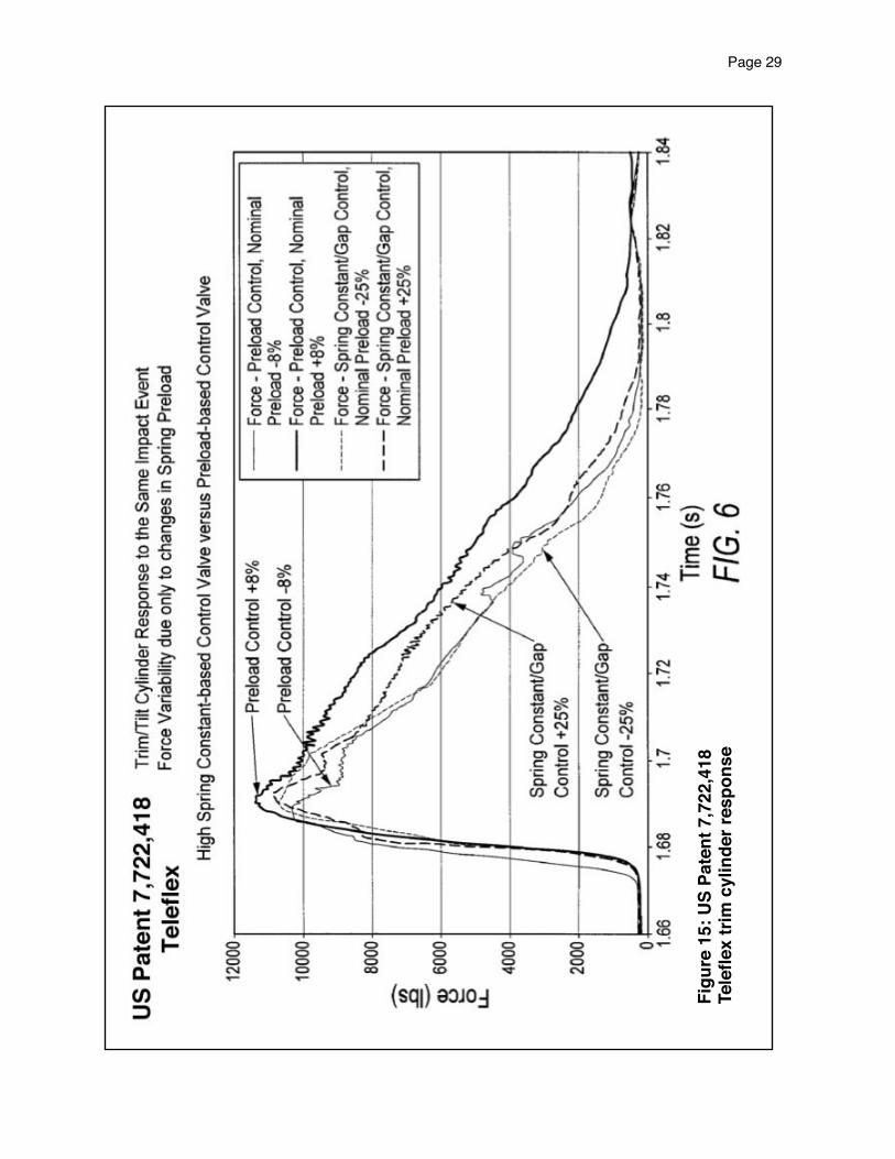
In 2010, Teleflex patented a trim / tilt cylinder log strike system design in which the traditional relief valve springs are heavier, but the preload is less. See US Patent 7,722,418 drawings in Figure 14. Preload is the amount of force generated by the spring when the hydraulic pressure is zero, which relates to how far the spring is compressed when the hydraulic pressure is zero.
Teleflex says the springs typically used in trim / tilt system relief valves have a spring constant of approximately 200 to 400 pounds per inch, meaning it takes 200 to 400 pounds to compress them one inch. Teleflex proposes a heavier spring constant in the range of 875 pounds per inch. They claim that by using this higher spring constant and by controlling the maximum size of the orifice when the spring guide contacts its upper stop, there is much less sensitivity to spring preload.
Conventional trim / tilt cylinders often use six relief valves (spring loaded balls). The high spring constant design only requires four.
A byproduct of the heavier springs, is lower preloads allow the relief valves to open at relatively low pressures and dissipate energy from low energy impacts.
We suggest, the high spring rate design also allows the relief valves to open faster in really high impacts (they crack open at lower pressures) which would reduce the peak loads at impact OMC discussed in their 5,195,914 patent.
In addition, if Teleflex were to install all 6 relief valves, instead of four, pressures would be more controlled under higher speed impacts of fixed or almost fixed objects.
Figure 15 shows forces generated in the trim / tilt cylinder rod during an impact, and the variability in those forces based on light springs or heavy springs with changes in preload. For example, heavy springs with preloads ranging from plus 25 percent to minus 25 percent of the target preload create less variance in pressures than light
Page 26!

springs with preloads ranging from only plus 8 percent to minus 8 percent of the target preload. Heavy springs also result in a lower peak force.
Similarly, Figure 16 shows cylinder stroke (travel) vs. time for the same impact is much more consistent with heavier springs and controlled orifice size than for lighter springs and a less controlled orifice size.
Page 27!

Figure 14: US Patent 7,722,418 Teleflex shock piston relief valve
Page 28!
Figu
re 1
5: U
S Pa
tent
7,7
22,4
18Te
lefle
x tr
im c
ylin
der r
espo
nse
Page 29!

Figu
re 1
6: U
S Pa
tent
7,7
22,4
18Te
lefle
x tr
im c
ylin
der s
trok
e re
spon
se
Page 30!

Showa patented an outboard tilt cylinder based on the use of a “flexing disk blow-off assembly”. They claim the valve can open a large flow path at lower pressures and quickly seats after the event. The relief valve is composed of a flexible disk / washer (item 112 in Figure 17) that covers up ports from the rod side. When rod side pressure spikes, the periphery of the disk bends away from its seat to allow fluid to exit. Showa says the design can be used as one large flexible disk or as several smaller ones.
Figure 17: U.S. Patent 6,280,268 Showa flexible disk blow off valve
Page 31!

Outboard manufacturers are continuing to produce larger outboards for recreational use. Some manufacturers produce outboards for commercial use, and some produce racing outboards. Motor mounts and swivel brackets designed for larger outboards, commercial outboards, or racing use could be pushed down the product line to smaller outboards to increase their capacity.
Page 32!

7. Active Control
This section builds on the discussion in Section 6 of trying to achieve maximum performance from the existing system. Taking active control of tilt cylinder rod forces, tilt system pressures, and/or stresses in the swivel bracket is the ultimate way to get the most out of the existing system.
Magneto-Rheological (MR) fluids make this possible. The apparent viscosity of smart fluids can be controlled with an electromagnet. MagneRide MR shock absorbers have been OEM installed on several production luxury automobile models for over a decade.
A cutaway of a Delphi MagneRide is shown in Figure 18. In 2009, Bejing West Industries (BWI) acquired the Chassis Division of Delphi that builds MagneRide.
MR shocks have been used in marine applications. For example, in 2013, Shockwave Marine Suspension Seating supplied Magneto Rheological Active Damping seats (MRAD) for vessels in rough water marine applications.
While active control using MR fluids may not yet be ready for tilt cylinder applications (they are expensive, may still require the use of a traditional tilt cylinder, may still need some marinization before widespread recreational marine use), they do hold some promise for the future.
MR shocks could also be very useful in tuning todays relief valve design to stop the upward swing of the drive without overloading other components. Just install an MR shock in place of the tilt cylinder during log strike testing and experiment to find the best damping profile. Then design the trim cylinder cushioning system to approximate that profile.
As to the ability of an MR system to respond fast enough and to handle the loads, we cite the automotive bumper reference and a Navy seat reference below:
“Frontal Crash Mitigation using MR Impact Damper for Controllable Bumper.” David Woo, Seung-Bok Choi, Young Tae Choi, and Norman M. Wereley. Journal of Intelligent Material Systems and Structures. A Sage journal. Vol.18. Pgs.1211-1215. (December 2007).
Adaptive Magnetorheological (MR) Shock Absorbers for High Speed Watercraft Seats. Presented by Gregory Hiemenz. Multi-Agency Craft Conference. 14 June 2011. Little Creek - Fort Story, VA.
Page 33!

Figu
re 1
8: D
elph
i Mag
neR
ide
Page 34!

8. Stops at Top of the Swing
When an outboard motor strikes a submerged object and flips up, a mechanical stop that limits maximum tilt to a point as the tilt cylinder rod reaches maximum extension can help stop the drive.
The presence of a secure, heavy duty stop may stop the drive if most of its energy has been expended. However, if a large drive is still coming up at a high rotational speed, the stop may just cause it to break off and fly into the boat.
As an alternative, a properly placed crushable stop at the top before the trim cylinder reaches maximum extension may be able to stop the drive without putting more force into the areas already being stressed.
If the tilt cylinder and the components to which it is attached were strong enough, a crushable block might be included inside the tilt cylinder near the rod end. When the piston flies up and hits the internal block, the block could crush and allow an inch or two more rotation as it absorbs the load. While this would probably result in a failure of the trim system, trim system failure would be preferable to the outboard breaking loose and flipping up into the boat or breaking free and falling into the lake.
Page 35!

9. Swim Platforms
Many recreational boats have swim platforms. They provide easy access to the water and are great for water skiing or tubing. Outboard boat swim platforms typically consist of two pads, one on either side of the outboard motor. A few outboard swim platforms encircle the outboard motor and could provide some resistance against the outboard flipping up into the boat.
Some houseboat swim platforms / swim decks extend out over outboard motors and provide considerable resistance to outboards flipping into the boat, but most houseboats go so slow it is not an issue for them. Figure 19 shows a houseboat swim platform with an outboard engine cover that doubles as a seat. The engine cover is shown rotated up to the open position.
Figure 19: Houseboat Swim Platform Outboard Engine Cover
Page 36!

10. Outboard Brackets
Sometimes called transom brackets, Gill brackets, motor brackets, or outboard brackets, they allow the outboard to run a couple feet further back behind the boat in cleaner water. Bracket manufacturers say they improve efficiency, reduce fuel consumption, provide additional floatation and stability, and provide a more economical alternative when re-powering an older stern drive boat.
Some are constructed as flat pads like the example from Armstrong Nautical Products shown in Figure 20. Others look more like fiberglass additions to extend the hull, and some are just mechanical brackets.
Figure 20: Armstrong Nautical Products Outboard Bracket
Outboard brackets lower the center of gravity of the outboard, allow use of shorter drive legs as their propellers typically run higher in the water, and the transom could provide a physical barrier to drives entering the boat. In addition, outboard brackets could be designed to extend during collisions to lengthen the time of contact and reduce peak loads.
Page 37!

11. Mechanical Fences, Engine Crash Bars, Tow Bars, Roll Over Bars, & Poling Platforms
When Mercury Marine was conducting open water log testing, they used mechanical screen fences at the transom to prevent drives and parts of drives from flipping into the boat as seen in the stern drive log strike photo, Figure 21. We used a filter on the photo to prevent copyright theft of the original image.
The drive is clearly visible at the stern. It has flipped vertically 180 degrees and is trying to enter the boat, propeller first, at the screen.
Page 38!

Figu
re 2
1: M
ercu
ry M
arin
e on
wat
er lo
g st
rike
test
ing
Tran
som
fenc
e pr
even
ts s
tern
driv
e fr
om e
nter
ing
boat
Page 39!

Several government and commercial outboard boats have engine crash rails extending from the stern and going around the outboards. Crash rails call attention to the engine’s location and prevent inadvertent backing of engines into above water objects or structures. They also prevent towed boats, approaching boats, or Personal Watercraft (PWC) from striking the engines.
If a crash rail were strong enough, properly placed, and if the transom to which it is mounted is strong enough to absorb the load, it could stop the upward swing of an outboard after it struck a submerged object. Figure 22 shows commercial vessel versions of these bars from Boston Whale and from Munson. The engine crash bar on Munson’s aluminum boat looks very sturdy.
Some commercial boats have tow bars mounted across the width of the vessel near the stern. These bars, properly designed, could also be of use in preventing an outboard from entering the boat. For example, see the tow bars on the Boston Whalers in Figure 22 and Figure 23.
Page 40!
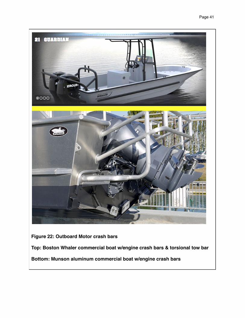
Figure 22: Outboard Motor crash bars
Top: Boston Whaler commercial boat w/engine crash bars & torsional tow bar
Bottom: Munson aluminum commercial boat w/engine crash bars
Page 41!

Some small commercial boats used in rough water have roll bars (see Figure 23) that, properly designed, could prevent an outboard from further entering the boat.
Figure 23: Boston Whaler with engine crash bars, torsional tow bar, and roll over bar
I took the photo in Figure 23 through a chain link fence at Kaw Lake near Ponca City Oklahoma in May 2012. This U.S. Army Corps of Engineers lake patrol boat has outboard motor crash rails, a torsional tow bar, and a roll over bar with some lights and a radio antennae mounted to it.
One or more of these bar systems (crash rails, torsional tow bars, or roll over bar), properly designed, could prevent an outboard motor from further entering the boat after striking a submerged object.
Page 42!

TurboSwing manufacturers a towed sports tow bar, TurboSwing (Figure 24). They also manufacture a heavy duty version, TowRescue, for commercial towing and workboat applications. Similar in design to engine crash rails, both products offer design opportunities to restrict outboards from flipping into boats.
Figure 24: TurboSwing
Page 43!

We have seen some poling platforms (ladders to a flat platform flat to stand above the outboard motor area and push the boat along in shallow water with a long pole) that might be redesigned to stop outboard motors from entering the boat. A poling platform by Custom Marine of Jacksonville, Florida is shown in Figure 25.
Figure 25: Custom Marine Poling Platform
Page 44!

12. Reduce the Weight of Outboard Motors
Outboard motors flip into the boat after striking submerged objects in part because of their mass. When the lower leg strikes something, the leg begins to rotate backwards and upwards. Modern, large, higher horsepower outboard motors are heavy. All that weight begins to rotate. If the mass and rate of rotation is too great for the log strike system to handle, the swivel bracket, jack plate, or other parts may fail, the outboard flips over itself and enters the boat.
Among the techniques for making outboard motors lighter are:
1. Modern clean direct injected two-strokes are generally lighter than four-strokes of the same horsepower rating
2. Use twin outboards. Reports of both twin outboards striking an obstruction are rare. Even if they did, the individual outboards would each be considerably lighter than the single outboard they replaced.
3. Apply an improved version of Volvo Penta’s XDP Ocean Series composite stern drive technology (composite gear case) to outboards to reduce weight
4. Reduce the horsepower by changing to a lower horsepower outboard. Cleaning the hull and removing excess weight and accessories can regain some of the lost speed, as can changing to a smaller, lighter boat, and to a stainless steel propeller.
Stainless steel propellers improve performance (thinner prop blades run to higher RPMs), but add weight to the outboard that may contribute to it breaking free.
Page 45!

13. Outboard Shallow Drives, Mud Drives and Surface Drives
Several specialty outboard manufacturers produce outboard motors under 40 horsepower for running in very shallow water, muddy conditions, and stumpy waters.
Their products tend to fall into three camps:
1. Long shaft outboards, such as the 35 horsepower Vanguard Go Devil.2. Outboard surface drives such as the 35 horsepower Beavertail Vanguard.3. Slightly conventional looking outboards like the 36 horsepower Pro-Drive outboard.
Examples of these three types of specialty outboards are shown in Figure 26.
By running so high in the water they are mostly protected by the boat. By pulling what corresponds to their nose cone up to the engine, and by avoiding leading vertical edges, these outboards significantly reduce their propensity to kick up into the boat.
Not as extreme, several outboard manufacturers, including Mercury Marine and Yamaha, offer a “Shallow Water Drive” feature, option, or kit for their conventional outboard motors. “Shallow Water Drive” provides one or more trim positions beyond the normal trim range for use in very shallow water at off-plane speeds. The result is “some” forward thrust for navigating and steering in conditions the outboard would normally hit bottom.
Page 46!

Vanguard Go-Devil
Beavertail Vanguard Surface Dive
Pro-Drive
Figure 26: Outboard Specialty Drives
Page 47!

14. Replace Some Outboard Motors With Alternative Drives
Some types of marine drives can utilize reconfigured outboard motors (outboard powerheads with alternative versions of lower units) and are less likely to flip into the boat.
Among these drive types and proposed drive types are:
1. Tunnel drives2. Pod drives3. Jet drives (intake in bottom of hull)4. Outboard well drives / inboard outboards / hidden outboards (see list below)
Major marine manufacturers have proposed and/or launched several outboard drives in which the outboard is either down in a well (in a hole) or is hidden, typically by fiberglass panels. Some of these drives have been called inboard outboards (because the outboard motor is ahead of the transom and not visible). This whole group of drives provides opportunities to prevent the drive from entering the operator and passenger area of the boat. Several of these outboard drives and applications are listed below:
1. L-drive (Chrysler, Force, U.S. Marine / Bayliner, Mercury Marine)2. OMC Quiet Rider3. Mercury Marine US Patent 5,108,325 (for a Mercury L-drive)4. Bombardier US Patent 6,609,9395. Sea Ray Venture 3706. Pursuit SC 365i7. Houseboat swim platform application (see Figure 18)8. Corsiva 590 tender and Corsiva 690 tender (new in the UK in 2012)9. Chris Craft 17 foot Lancer outboard (many years ago)10. De Antonio Yachts D23 motor boat (new in Spain in 2012)11. Sailboats have used hidden outboards for decades
We will now briefly illustrate several of these approaches so our readers can better visualize how they could help prevent outboard from flipping into the boat, especially if extra attention was devoted to accomplishing that during their design.
Page 48!

L-drive (Chrysler, Force, U.S. Marine / Bayliner, Mercury Marine)
The L-drive shown in Figure 27 was known by many company names as it passed though several companies during its production. Basically, they took an outboard motor, turned the engine to one side, and stuck the leg through the bottom of the hull. The L-drive steers, trims, and tilts the lower leg while the powerhead section remains stationary. U.S. Marine won a Design News Excellence in Design Award for the L-drive in 1989.
Page 49!

Figure 27: U.S. Marine L-driveimages from Design News March 27, 1989
Page 50!

OMC Quiet Rider
Outboard Marine Corporation’s Quiet Rider shown in Figure 28 was their response to the L-drive. OMC mounted an outboard through a fiberglass swim platform, covered it with a fiberglass shell, and supplied intake air to the outboard via a snorkel. This gave OMC and their boat lines access to an L-drive type product with an invisible outboard.
Figure 28: OMC Quiet Riderimage from Popular Mechanics February 1992 page 75
Page 51!

Mercury Marine US Patent 5,108,325 (L-drive patent)
Later Brunswick patents refer to US Patent 5,108,325 seen in Figure 29 as Mercury Marine’s L-drive patent. It is a through hull drive with a u-joint in the lower section to allow steer, trim, and tilt. This may represent a drive Mercury called the Mirage that did not make it to production.
Figure 29: US Patent 5,108,325 Mercury Marine L-drive
Page 52!

Sanshin U.S. Patent 5,088,945 (Nose Over Drive)
In 1992, Sanshin (now Yamaha Marine), in the spirit of the L-Drive, patented an outboard with the engine turned 90 degrees forward into the boat as seen in Figure 30. They went on to file at least two more patents on this design. It provides an easy opportunity to tie the drive down with a strap over the transom.
Figure 30: U.S. Patent 5,088,945 Sanshin Nose Over Drive
Page 53!

Bombardier US Patent 6,609,939
Bombardier Recreational Products laid claim to a “hidden” outboard drive with their U.S. Patent 6,609,939 seen in Figure 31. Bombardier refers to it as a drop down installation, referring to how the outboard powerhead can be dropped down and affixed to the hull. The lower unit bolts up from the bottom. Once installed, it is hidden from view by a cover.
Figure 31: US Patent 6,609,939 Bombardier drop down installation
Page 54!

Sea Ray 370 Venture
In model year 2013, Sea Ray launched “hidden” outboards in a large 37 foot boat known as the Sea Ray 370 Venture. Most previous “hidden”, “well”, inboard outboard attempts were confined to boats at least 10 feet shorter in length. Seen in Figure 32, the design places large twin Mercury Verado outboards in wells at the stern with snorkels to the side for intake air. By spreading the two outboard wells, and allowing a walk through between them, the vessel is able to have a flat, full width, full size swim platform.
Sea Ray 370 Venture was named 2012 boat of the year by the editors of Boating Magazine.
Page 55!

Figure 32: Sea Ray 370 Venture, photos by Sea Ray
Page 56!

Pursuit SC 365i
Pursuit introduced the SC 365i sports yacht in late 2012. In the same class as Sea Ray’s 370 Venture, both these vessels extend the use of outboard wells beyond their previous targets. Pursuit mounts twin large Yamaha outboards in theirs, and mounts them closer together than Sea Ray did. Pursuit offers a walk though path along one side of the outboard enclosure to a flat, full width swim platform as seen in Figure 33.
Page 57!

Figure 33: Pursuit SC 365i, images from Pursuit brochure
Page 58!

15. Alternative Swivel Bracket Designs
Outboard swivel brackets allow modern outboards to steer, tilt, and trim. When floating or submerged objects are struck by the outboard motor, swivel brackets allow the outboard to swing up and over the obstruction, then settle back down, all while being positively retained to the transom.
As modern outboard motors grow in horsepower, size, and weight, they propel boats faster. More mass (boat plus outboard plus contents of the boat and fuel) at higher speeds results in more stress being place on outboard swivel brackets during collisions with floating or submerged objects.
Outboard motors, especially larger outboard motors, breaking loose and flipping into boats after striking floating or submerged objects often result from a broken swivel plate.
A typical swivel bracket from Mercury Marine is shown in Figure 34 with the two axis of rotation identified. The feet of the bracket, labeled lower trim limit, settle down against a rod to establish the limit of trim under (rotating the lower leg under the boat).
The highly complex shape of Mercury’s swivel bracket in Figure 34, along with the thinness of the material, the two upper arms from the trim & tilt axis of rotation, and the thin shell around the steering axis of rotation provide multiple sites for potential failures / breakage. We are not saying swivel brackets are under designed, we are saying high impact loads resulting from striking floating or submerged objects can cause them to fail in some situations.
Page 59!

Figure 34: Typical Outboard Swivel Bracket, Mercury Marine
An example of a failed Mercury Marine 150 horsepower outboard swivel bracket is shown in Figure 35 and Figure 36. It fractured near the top viewed from the stern. The steering axis pole broke out of its tube shaped confinement, allowing the outboard to break free.
Page 60!

Figure 35: Failed Swivel Bracket150 horsepower Mercury Marine
Page 61!

Figure 36: Failed Swivel Bracket150 horsepower Mercury Marine closeup
Page 62!
Several alternative designs have been proposed for swivel brackets, especially for those used in special / niche applications.
One problem with large outboards is the space required for the powerhead to turn when steering the boat. Larger engines on outboard legs require the outboard to be set back some from the boat or the engine to hang over the transom and have considerable space to rotate when steered. A Sanshin (predecessor to Yamaha Marine) swivel bracket, US Patent 5,224,888 shown in Figure 37 addresses this problem.
The Sanshin bracket allows the outboard powerhead to be dropped in place similar to some of the L-drives. Its lower leg can be rotated below the swivel bracket for steering. While some of the other proposed drives move both trim and steering functions below the powerhead, Sanshin only moved steering to the lower leg. Trim and tilt remain conventional, except for interacting with their newly designed swivel bracket.
Page 63!

Figure 37: US Patent 5,224,888 Sanshin Swivel Bracket
Page 64!

Figure 38: US Patent 5,224,888 Sanshin Swivel Bracket Installed
Sanshin’s swivel bracket is shown installed above. While Sanshin set out to provide a more compact installation for outboards, their proposed swivel plate design as seen in Figure 37 and Figure 38 offers opportunities to be much stronger than a traditional bracket. Its shape is far less complex, plus it offers opportunities to be made thicker, to have a full width connection to a solid tilt tube / through tube, and for the use of gussets to further strengthen the design.
Existing swivel bracket failures often involve the vertical pole conventional outboards rotate around, breaking away from the swivel bracket. The vertical pole is no longer present in Sanshin’s design. While stress calculations, computer modeling and testing would be required to confirm our suppositions, it appears Sanshin’s proposed bracket could practically be made considerably stronger than a conventional swivel bracket for the same application. Additionally, rotating the lower unit for steering provides an opportunity to allow the lower unit to break away in a collision similar to break away designs discussed earlier.
Page 65!

Related Topics
Page 66!

A. Utilize the Fracture Mechanics of Wood
Today’s log strike systems are designed around the premise of trying to get the drive to flip up and over the log, then settle back down to its original depth.
Wood exhibits elasticity and plasticity when being crushed at speed. At some point, the wood begins to break/split in font of the leading edge of the drive and the force actually goes down.
In some circumstances, impact forces can be greater when allowing the drive to swing up, than if the drive were locked down (when the boat had enough speed, mass, and the drive was rigid enough to cut through the log after the log began to fail plastically).
With wood (floating logs, stumps, driftwood, sunken trees, wooden structures, etc) being among the most commonly stuck objects we encourage further study of how wood fractures in this situation. Then applying that knowledge to build better log strike systems.
We suggest some search terms and references below. The wood and impact journals cited contain many other references that may also be of interest.
Search Terms:
1. Linear-Elastic Fracture Mechanics (LEFM) of wood2. Elasto-Plastic Fracture Mechanics (EPFM) of wood using the J-Integral Method3. Added Mass (to accelerate a submerged object you must also accelerate some water
out of the way)4. Anistropic (many properties of wood are direction dependent)
References:
1. Drift-wood Collision Load on Bow Structure of High-speed Vessels. Yasumi Toyama. Marine Structures. Vol.22. Pgs.24-41. (2009).
2. Effect of Impact Velocity on the Fracture of Wood as Related to the Pulping Process. J.E. Berg. Wood Science and Technology. Vol.35. Pgs.343-351. (2001).
3. Impact of Water Storage on Mechanical Properties of Spruce as Detected by Ultrasonics. F. Efransjah, G. Kilbertus, and V. Bucur. Wood Science Technology. Vol.23. Pgs.35-42. (1989).
4. Historical and Present-Day References Concerning Impact on Wood. W. Johnson. International Journal of Impact Engineering. Vol.4. No.3. Pgs.161-174. (1986).
Page 67!

B. Slowing / Killing the Engine
This approach does not directly relate to keeping the outboard from entering the boat, but it reduces some risks once the outboard enters the boat. Some approaches listed earlier already tap into the engine / boat control system, so we listed this one here.
An outboard motor flying into the boat is a significant safety hazard, especially a large outboard. However, the same outboard with a propeller still rotating under power is far more dangerous. Several people have been critically injured or killed by outboard motor propellers still rotating under power when they enter the vessel. Steering cables and fuel lines tend to remain attached and the propeller turns at very high RPMs due to air being much less resistant to its rotation than water.
Log strike systems are designed to allow the outboard motor to flip up and over the obstruction. When the outboard motor’s propeller begins to clear the water, it begins to rotate much faster in air. The log strike system dissipates the impact energy, and the outboard motor settles back down in the water to its previous trim position. Some designs have tried to throttle back or kill the engine during collisions for various reasons.
Among early attempts were F.C. Krueger’s US Patent 2,917,019 filed in 1955 shown earlier as Figure 7. Krueger used a push rod to kill the engine as the lower part of this drive was allowed to swing backwards and upwards from a hinge during a collision.
Krueger was not the only early inventor to recognize the need to slow or kill the engine when the drive or part of the drive swings up. Edwin B. Nolt of Sperry Rand filed a similar claim in 1960 which eventually issued as US Patent 3,036,543.
At that time, large outdrives were as large as 300 horsepower and outboards were reaching 80 to 100 horsepower. When an object is struck and the drive swings up clear of the water, the propeller rotates much faster. When the now very rapidly rotating propeller swings back down and reenters the water, it can cause a sudden jolt. This jolt may cause those on board to fall or be tossed into the structure of the boat. In addition, the engine may be burnt out from the ultra high RPMs reached while the propeller was out of the water, and the transom might be damaged from the shock when that high speed propeller reenters the water. Lastly, damage to the propeller can be minimized by stopping its rotation as soon as something is struck.
Nolt proposed a means of automatically protecting the boat by reducing the speed of the engine or by killing the engine when the propeller swings up. He used a push rod activated by the drive when it swings up to reduce a throttle. Nolt similarly used the upward swinging drive to make and break contacts to kill the engine.
Page 68!

Sanshin (predecessor to Yamaha Marine) filed in 1986 what became US Patent 4,734,065 for a collection of methods to detect the outboard motor has struck something and the propeller is rotating in the air. The patent covers their detection methods and their techniques for throttling back the engine. The first page of Sanshin’s patent is shown in Figure 39.
According to Sanshin:
“Although permitting popping up of the outboard drive when an underwater obstacle is struck protects the outboard drive, when the outboard drive returns to its normal running position, there can be certain unsatisfactory conditions arise in the resulting watercraft. For example, the rapid change of trim can produce a surging in the condition in the watercraft that can upset the passengers, it can cause a rolling operation of the watercraft or it could result in an abrupt and unexpected turn in the watercraft’s direction. Although these conditions are less objectionable that those which would result it popping up were not permitted, it would be desirable if they could be voided.”
Sanshin enumerates the methods they propose achieve stability of the vessel after the outboard motor pops up by slowing the speed of the outboard engine for a time period after it returns to its normal position. Sanshin lists four ways of detecting impact with a submerged object:
1. Pressure sensor on rod end of trim / tilt cylinder2. Change rate of trim angle as measured from the trim position indicator (how fast the
trim position is changing)3. Trim position moved to outside normal trim positions4. Impact sensor mounted to front lower end of outboard drive
Sanshin says they can slow the engine at least three ways:
1. Misfiring cylinders2. Reduce fuel flow3. Throttle intake air
Sanshin’s patent also teaches using a throttle position sensor and a comparator circuit to prevent slowing the engine if it is already at a low throttle position and killing the engine.
CONTINUED
Page 69!
We suggest similar techniques could be used to detect breakaway of the outboard motor, and to kill the engine in those conditions. Additional indicators the outboard has broken free and may enter the boat include:
1. Steering cable tension2. Engine RPM spike for more time than a normal strike and settle back down3. Outboard is upside down (rotates over itself)4. Loud noise (swivel bracket broke)5. Sudden deceleration of the vessel6. Shock load to the boat when drive lands in boat7. Drive is gone from the transom8. Propeller torque (impacting things other than water)9. Swivel bracket is no longer in one piece10. Jackplate slide vertically exited its track11. Sudden change in forward stress of major hull components (drive no longer pushing
boat) that lasts longer than a normal log strike and settling back down, or than hopping a wave or wake.
12. Monitoring the grounding (continuity) wires on components likely to break free
Two or more indicators could be used together to help reduce false alarms (false positives).
Now, with CAN-BUS, SmartCraft (Brunswick / Mercury Marine), Electronic Vessel Control / EVC (Volvo Penta), I-Command (Bombardier Recreational Products / BRP), Command Link (Yamaha), K-Line (Honda), NMEA 2000, and other similar network bus systems along with engine control modules (ECMs), it is easy to detect the engine over revving following a collision with a floating or submerged object, quick changes in boat velocity, and other variables indicative of a collision or the outboard propeller rising above the water. For example, see Figure 40, Brunswick’s 2001 US Patent 6,273,771, Control System for a Marine Vessel. Brunswick’s and similar bus systems from Brunswick’s competitors, could be used to throttle the engine back, and to kill the engine in instances in which the drive is detected to have broken free.
Page 70!

Figure 39: US Patent 4,734,065
Page 71!
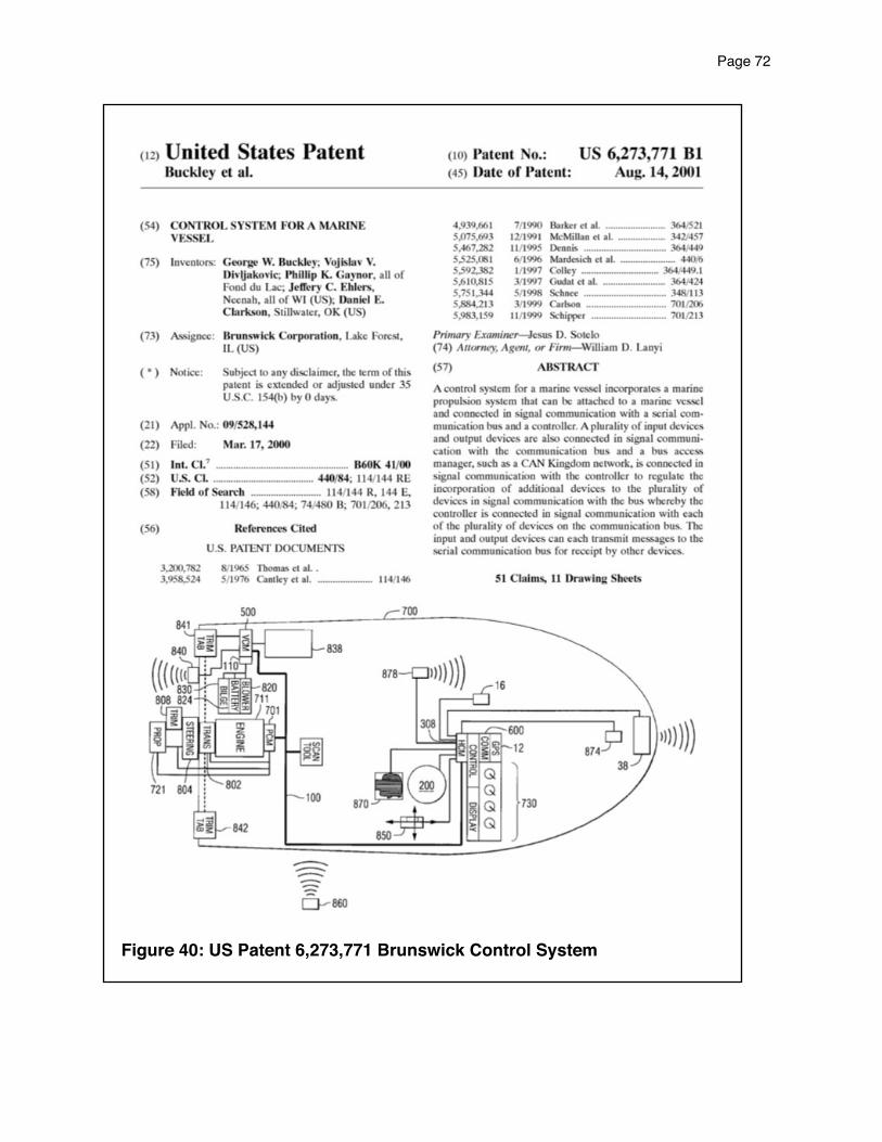
Figure 40: US Patent 6,273,771 Brunswick Control System
Page 72!

Closing Thoughts& Comments
Page 73!

Closing Thoughts
In modern times, large outboards are flipping into boats and injuring or killing those on board with their engine running and the propeller rotating at very high speeds. Krueger and Nolt both showed this could have been stopped over half a century ago.
Recreational boating has matured to a very broad range of boaters, activities, vessels, and waters. As a result there are few “one size fits all” cures. In this instance (preventing outboard motors from flipping into boats) we suggest marine drive manufacturers, boat builders, and boat dealers consider the risk level of their products and consider employing the solutions proposed in this report and others when appropriate.
One place to begin, fishing boats powered by large outboards are disproportionately represented on our accidents list (Triton, Ranger, Phoenix, Bass Cat, and others).
We also direct your attention to our Preventing & Mitigating Injuries & Fatalities from Outboard Motors Flipping into Boats page which includes a large spreadsheet that identifies many other opportunities to prevent or mitigate these accidents.
Thank you for your attention to this topic. Please pass this paper along to others who may find it useful.
Comments
We welcome your comments and suggestions regarding this article. Please visit PropellerSafety.com, click on the contact us tab on the top menu, and share your thoughts with us.
Page 74!