approach to improve beam quality of inter-satellite optical communication system based on...
TRANSCRIPT

Approach to improve beam quality ofinter-satellite optical communicationsystem based on diffractive optical
elements
Liying Tan 1, Jianjie Yu1,∗, Jing Ma1, Yuqiang Yang1,2, Mi Li 1, YijunJiang1, Jianfeng Liu1, and Qiqi Han1
1National Key Laboratory of Tunable Laser Technology, Harbin Instituteof Technology, Harbin 150001, China
2Institute of Application Science, Harbin University of Science andTechnology, Harbin 150001, China
∗Corresponding author: [email protected]
Abstract: For inter-satellite optical communication transmitter withreflective telescope of two-mirrors on axis, a large mount ofthe transmittedenergy will be blocked by central obscuration of the secondary mirror. Inthis paper, a novel scheme based on diffractive optical element (DOE) isintroduced to avoid it. This scheme includes one diffractive beam shaperand another diffractive phase corrector, which can diffract the obscured partof transmitted beam into the domain unobscured by the secondary mirror.The proposed approach is firstly researched with a fixed obscuration ratioof 1/4. Numerical simulation shows that the emission efficiency of newfiguration is 99.99%; the beam divergence from the novel inter-satelliteoptical communication transmitter is unchanged; and the peak intensity ofreceiver plane is increased about 31% compared with the typical configura-tion. Then the intensity patterns of receiver plane are analyzed with variousobscuration ratio, the corresponding numerical modellingreveals that theintensity patterns with various obscuration ratio are nearly identical, butthe amplify of relative peak intensity is getting down with the growth ofobscuration ratio. This work can improve the beam quality ofinter-satelliteoptical communication system without affecting any other functionality.
© 2009 Optical Society of America
OCIS codes:(060.4510) Optical communication; (050.1970) Diffractive optics
References and links1. M. Katzman, ed., Laser Satellite Communications, (Englewood Cliffs, N.J., Prentice-Hall, 1987).2. P. Henneberg and H. Schubert, “A new telescope concept forspace communication,” Proc. SPIE1218, 153-159
(1990).3. A. Yamamoto, T. Hori, T. Shimizu, and K. Nakagawa, “Japanese first optical inter-orbit communications engi-
neering test satellite (OICETS),” Proc. SPIE2210, 30-38 (1994).4. H. Hemmati and N. Page, “Preliminary opto-mechanical design for the X2000 transceiver,” Proc. SPIE3615,
206-211 (1999).5. M. Knapek, J. Horwath, N. Perlot, and B. Wilkerson, “The DLR ground station in the optical payload experiment
(STROPEX) - results of the atmospheric measurement instruments,” Proc. SPIE6304, 63041U (2006).
#104811 - $15.00 USD Received 4 Dec 2008; revised 25 Feb 2009; accepted 20 Mar 2009; published 2 Apr 2009
(C) 2009 OSA 13 April 2009 / Vol. 17, No. 8 / OPTICS EXPRESS 6311

6. W. N. Peters and A. M. Ledger, “Techniques for matching laser TEM00 mode to obstructed circular aperture,”Appl. Opt.9, 1435-1442 (1970).
7. B. J. Klein and J. J. Degnan,“Optical antenna gain 1 : transmitting antennas,” Appl. Opt.13, 2134-2141 (1974).8. O. D. Christy, “Dual-secondary mirror Cassegrain optical system,” U. S. Patent4,439,012, Mar 27 (1984).9. X. L. Kong and P. M. Hao, “New method to remove central shadefor reflecting laser beam expander,” Chin. J.
Quantum Electron.19, 205-209 (2002).10. H. Hemmati and N. Page, “Approaches for efficient coupling of lasers to telescope with secondary mirror and
baffle obscuration,” Proc. SPIE4635, 288-294 (2002).11. C. W. Chen, “Re-imaging optical system including refractive and diffractive optical elements,” U. S. Patent
5,287,218, Feb 15 (1994).12. R. N. Smartt and E. W. Cross, “Advances in spherical-mirror telescopic systems design: application to large-
aperature solar coronagraphs,” Opt. Eng.41, 2055-2058 (2002).13. Z. Liu, H. Zhao, J. Liu, J. Lin, M. A. Ahmad, and S. Liu, “Generation of hollow Gaussian beams by spatial
filtering,” Opt. Lett.32, 2076-2078 (2007).14. Z. Liu, J. Dai, X. Sun, and S. Liu, “Generation of hollow Gaussian beam by phase-only filtering,” Opt. Express
16, 19926-19933 (2008).15. W. B. Veldkamp and T. J. McHugh, “Binary optics,” Sci. Am.May, 50-55 (1992).16. R. W. Gerchberg and W. Saxton, “A practical algorithm forthe determination of phase from image and diffraction
plane picture,” Optik35, 247-246 (1972).17. J. R. Fienup, “Phase retrieval algorithms: a comparison,” Appl. Opt. 15, 2758–2769 (1982).18. G. R. Brady and J. R. Fienup, “Nonlinear optimization algorithm for retrieving the full complex pupil function,”
Opt. Express14, 474-486 (2006).19. C. Rydberg and J. Bengtsson, “Numerical algorithm for the retrieval of coherent beams from transverse intensity
measurements,” Opt. Express15, 13613-13623 (2007).20. B. Lin and N. C. Gallagher, “Convergence of a spectrum shaping algorithm,” Appl. Opt.13, 2470-2471 (1974).21. J. W. Goodman, Introduction to Fourier Optics, Second Edition, (New York, McGraw-Hill, 2006).
1. Introduction
As a kind of line-of-sight wireless transmission utilizinglight carrier, inter-satellite optical com-munication has became a subject of research interest since the advent of the laser. Comparingwith a RF or microwave system of same size, it could be much more efficient and could providedata rate and capability of a high orders of magnitude [1]. Anafocal or focal reflective opticaltelescope referred as a beam expander was commonly used in inter-satellite optical commu-nication or ground-to-satellite optical communication system [2-5], which made an action incompressing beam divergence, reducing the field of view as well as increasing receiving en-ergy. For inter-satellite optical communication transmitter with reflective optical telescope oftwo-mirrors on axis, unfortunately, a considerable amountof the beam energy is lost for cen-tral obscuration of secondary mirror. Accordingly, emission efficiency of inter-satellite opticalcommunication transmitter and beam power density in far-field will be both decreased.
Different approaches have been proposed to avoid the secondary mirror obscuration. Gener-ally, they can be classified into two groups according to whether secondary mirror positioned onaxis or not. One can find that many existing optical elements or devices have been introduced inthe former group, such as axicon optical element [6,7], dual-secondary mirror [8], cone reflect-ing mirror [9], prism beam slier and beam-splitter/beam combiner [10], etc. Low transmissionefficiency is mutual defect of these schemes, and most of themhave extraordinary drawbackssuch as overfull optical elements, low flexibility or difficult to manufacture. In the latter case,the secondary mirror on-axis is replaced by more than one off-axis fold or turning mirrors, andthe off-axis tertiary reflective surfaces will be structured to avoid central obscuration [11,12].However, they are not suitable for space applications for strict assembly, lower stability, andlarger size. So, how to improve transmitted beam quality with intrinsic bulk, mass, and powerconsumption is becoming a topic of interest. Here, we represent a method adopting two DOEs,which rearrange the transmitted beam with Gaussian intensity profile into a hollow Gaussianbeam [13,14] to avoid the secondary mirror obscuration.
The structure of this paper is arranged as follows: a basic configuration of the system contain-
#104811 - $15.00 USD Received 4 Dec 2008; revised 25 Feb 2009; accepted 20 Mar 2009; published 2 Apr 2009
(C) 2009 OSA 13 April 2009 / Vol. 17, No. 8 / OPTICS EXPRESS 6312

ing two DOEs for improving beam quality of inter-satellite optical communication transmitteris described in Section 2. The design of DOE and beam transformation within inter-satelliteoptical communication system are addressed in Section 3. InSection 4, we present the numer-ical modelling of DOE for beam shaping and corresponding far-field pattern. At last section, asummarization is given.
2. Improved inter-satellite optical communication transmitter configuration
The typical simplified scheme of inter-satellite optical communication transmitter is illustratedin Fig. 1, which includes: (1) laser source; (2) beam collimator; (3) reflective optical antenna. Asshown in Fig. 1, when the transmitted beam emitting from fiber-coupled laser diode (FLD) hasbeen collimated, a monochromatic plane-wave with Gaussianintensity profile will be achievedin plane P1. Successively, light beams will arrive at the secondary mirror perpendicularly andthen be reflected onto primary mirror. Finally, the solid Gaussian beam is degenerated into ahollow Gaussian beam (HGB) in plane P3 (i.e., the exit pupil plane) for the central obscurationof secondary mirror. Obviously, when the beam leaves from plane P3, lots of the beam energyhas been lost .
FLD
collimator
Primary mirror Secondary mirror
P3
P1
3x
3y
Fig. 1. The typical simplified scheme of inter-satellite optical communication transmitter.
Comparing with the typical scheme, we introduce an improvedconfiguration of inter-satelliteoptical communication transmitter (as shown in Fig. 2) which can avoid energy loss by addingtwo DOEs. These two elements are placed between collimator and optical antenna along axis,and they act as a beam shaper and a phase corrector, respectively. Different from the typicalscheme, in this configuration, the central portion of collimated Gaussian beams in plane P1 willbe diffracted to annular domain beneath solid blue line in plane P2, which is the focal plane ofdiffractive beam shaper. Afterwards, the transmitted beamwill be rearranged to a plane wave bydiffractive phase corrector positioning in plane P2. Thus aHGB is achieved prior to secondarymirror. Since an afocal reflective telescope is usually considered as a linear beam expander,consequently a magnified HGB will be obtained in plane P3. Obviously, the intensity of eachpoint of the magnified HGB in Fig. 2 is larger than that of HGB inFig. 1, and the transmittedbeam won’t be blocked by secondary mirror when a proper innerdiameter of HGB in Fig. 2 isselected.
3. Design of DOE and beam transformation
3.1. Design of DOE
DOEs mentioned above are classified as pure-phase elements,which can be described by phasefunctions [15], so the phase profiles of both beam shaper and phase corrector must be preciselydetermined to obtain a lossless output beam. In this paper, only design scheme of DOE for
#104811 - $15.00 USD Received 4 Dec 2008; revised 25 Feb 2009; accepted 20 Mar 2009; published 2 Apr 2009
(C) 2009 OSA 13 April 2009 / Vol. 17, No. 8 / OPTICS EXPRESS 6313

Phase corrector
Beam shaper
FLD
collimator
Primary mirror Secondary mirror
P3
without DOE with DOE
P1 P2
3x
3y
Fig. 2. Improved configuration of inter-satellite optical communication transmitter.
beam shaping is demonstrated, which enables beams with Gaussian intensity profile to hollowGaussian intensity profile. Actually, the design for phase corrector is very simple, which can bereached only across a subtraction of phase functions between plane-wave and actual wave-frontof plane P2.
The design of DOE is similar to phase retrieval from intensity measurements. In fact, theintensity distribution of laser beam in plane P1 and the required hollow Gaussian intensitydistribution in plane P2 are all calculable or measurable, and hence the generation problem ofdiffractive beam shaper can be referred as a phase reconstruction from two known intensityinformation. Many optimization algorithms have been developed to compute phase profiles ofDOE [16-19], here GS optimization algorithm [16] will be proposed for it. The iterative GSalgorithm depends on a Fourier Transform relation between the waves in plane P1 and planeP2, Fig. 3 shows this iterative process.
IFFT
FFT
n n
n n
B B B
,exp
out n n nE B i,
expin n n n
E A i
,exp
in n n nE A i
Input plane P1 Reconstruction plane P2
1
1
n n
n n
A A A
0,
expout n n n
E B i
Fig. 3. Flow chart of GS algorithm.
As shown in Fig. 3, GS algorithm is an infinite loop of forward and backward transforms frominput plane P1 to reconstruction plane P2, the known sampledamplitude functionA andB areassigned to these two planes, respectively. To begin, a random phase distributionϕ0 is generatedto serve as the initial phase estimate and combined with the corresponding sampled amplitudefunction A to form input wave functionEin(x1,y1). Then, this synthesized complex discrete
#104811 - $15.00 USD Received 4 Dec 2008; revised 25 Feb 2009; accepted 20 Mar 2009; published 2 Apr 2009
(C) 2009 OSA 13 April 2009 / Vol. 17, No. 8 / OPTICS EXPRESS 6314

function is done by means of the Fast Fourier Transform (FFT)algorithm. The phase portionφ ′ of the complex wave functionE′
out(x2,y2) resulting from this transformation are computedand reserved, and it is combined with the corresponding sampled amplitude functionB. Thisnew complex functionEout(x2,y2) is then done by Inverse Fast Fourier Transform (IFFT), thephasesϕ ′ of the sample points are calculated and combined with the known sampled amplitudefunctionA to form a new estimate of the complex sampled input plane, andthe iteration processis repeated.
The phase mapping of two planes evolves through the iterations [16, 20] and eventuallycomes to a stable position or stopped on the condition:
SSE=
∫ ∞−∞
∫ ∞−∞ ||F (Ein)|−B|2dx2dy2∫ ∞−∞
∫ ∞−∞ |B|2dx2dy2
< ζ , (1)
whereSSEis the sum of squared error between the desired and computed amplitude functionof the reconstruction plane,F represents FFT,ζ is an infinitesimal. Finally, the phase map-ping representing the DOE data will be obtained across a subtraction between calculated phasemapping and initial phase of input plane-wave.
3.2. Beam transformation
As mentioned above, when the transmitted beam has been transformed to a HGB in plane P2,the phase pattern of this HGB is modified by a phase corrector placed in this plane and forma new plane wave. Subsequently, this new plane wave with hollow Gaussian intensity patternis magnified by optical antenna, and the emission efficiency of inter-satellite optical communi-cation transmitter is increased greatly for the absence of the secondary mirror obscuration. Inorder to evaluate the performance of the improved scheme, wedefine the emission efficiencyof inter-satellite optical communication transmitter as:
ηE =E′
E×100%, (2)
whereE represents the total beam energy emitting from light source, andE′ represents thebeam energy emitting from the exit pupil pupil.
The HGB leave from inter-satellite optical communication transmitter and transmit to oppo-site inter-satellite optical communication receiver apart from ten-thousands of kilometers viafree space, and the complex amplitude function of receiver plane can be computed by Fraun-hofer diffractive formula [21]:
E4(x4,y4) =ejkze
jk2z(x
23+y2
3)
jλz
∫ ∞
−∞
∫ ∞
−∞E3(x3,y3)exp
[
− jkz
(x3x4 +y3y4)
]
dx3dy3 (3)
=ejkze
jk2z(x
23+y2
3)
jλz·F{E3(x3,y3)} fx=
x4λz, fy=
y4λz
,
wherek = 2π/λ represents wavenumber,z is transmitted distance,fx , fy are spatial frequencyof receiver plane alongx-direction andy-direction, respectively.
The amplitudes are proportional to the square roots of the measured intensities, thus theintensity function of far-field (i.e. the plane of inter-satellite optical communication receiver)can be described as:
I4(x4,y4) =
(
1λz
)2
· |F{E3(x3,y3)}|2. (4)
#104811 - $15.00 USD Received 4 Dec 2008; revised 25 Feb 2009; accepted 20 Mar 2009; published 2 Apr 2009
(C) 2009 OSA 13 April 2009 / Vol. 17, No. 8 / OPTICS EXPRESS 6315

In order to check whether beam quality has been improved withthe improved scheme, thefar-field pattern of beams is analyzed, and a relative peak energy increment is used to evaluatebeam quality, which is denoted asηP:
ηP =I4max− I ′4max
I ′4max×100%, (5)
whereI4max andI ′4max are the peak energy of far field with and without DOE, respectively.
4. Numerical simulations
In the design of inter-satellite optical communication transmitter, the complex wave function ofexit pupil plane is usually known as design requirements, which includes the diameter of exitpupil, beam waist or beam divergence. Only when these parameters have been given, we candetermine the magnification of optical antenna, which is defined as the diameter ratio betweenprimary mirror and secondary mirror. The reciprocal of magnification is referred as obscurationratio, which is denoted asT. Obviously, the inner diameter of HGB in exit pupil plane varieswith T, so the intensity patterns of far-field are also varied withT. This variation prompts us toinvestigate the far-field intensity patterns with various obscuration ratio.
The complex wave function with rotational symmetry in exit pupil plane can be written as:
E3(r3) = C(r3) ·exp(iψ). (6)
In Eq. (5), the phase and amplitude of complex function can beobtained by phase correctorand beam shaper, respectively. The amplitude function is defined as:
C(r3) =
{
exp(−r23/ω2
03), if r30 ≤ |r3| ≤ r3m
0, otherwise, (7)
wherer3m, ω03, andr30 = r3m ·T represent the outer radius, beam waist, and inner radius ofrequired HGB profile, respectively.
Some parameters are made in the following section: wavelength λ = 800nm; the radius ofexit pupil planer3m = 10mm, corresponding beam waistω03 = r3m/
√2; the transmitted distance
between inter-satellite optical communication transmitter and inter-satellite optical communi-cation receiverz= 5×10⁷ m.
4.1. Design of DOE with fixed obscuration ratio
Considering a typical obscuration ratio ofT = 1/4, when the amplitude function of exit pupilplane has been given, the amplitude function of plane P2 and plane P1 in Fig. 2 can be deter-mined by
B(r2) =
{
c2 ·exp(−r22/ω2
02), if r20 ≤ |r2| ≤ r2m
0, otherwise, (8)
wherer2m = r3m ·T,ω02 = ω03 ·T, and r20 = r30 ·T represent the outer radius, beam waist,and inner radius of desired HGB profile in plane P2, respectively. c2 is an amplitude profilecoefficient, which makes a relation of conservation of energy between the waves of plane P2and P3:
A(r1) = c1 ·exp(−r21/ω2
01), (9)
#104811 - $15.00 USD Received 4 Dec 2008; revised 25 Feb 2009; accepted 20 Mar 2009; published 2 Apr 2009
(C) 2009 OSA 13 April 2009 / Vol. 17, No. 8 / OPTICS EXPRESS 6316

wherer1 ∈ [0, r1m], andr1m = r2m is the maximal spot radius of plane P1 in Fig. 2,ω01 = r1m/√
2is the corresponding beam waist. The action ofc1 is similar toc2, which ensures the energyconservation between plane P1 and P2.
After all parameters in Eq. (7) and Eq. (8) have been determined according to previous knownconditions, the phase function of diffractive beam shaper can be computed by using GS algo-rithm. While the algorithm reaches a stable position, the Gaussian beam as shown as Fig. 4(a)is transformed into a HGB as shown in Fig. 4(b). Figure 4(c) isthe lateral section of Fig. 4(b),which shows that a good consistency between computed amplitude and desired amplitude indespite of some perturbation. Simulation result shows thatthe emission efficiency of inter-satellite optical communication transmitter is as high as 99.99%, which is higher than that ofthe condition without DOE greatly.
Fig. 4. The beam transformation in inter-satellite opticalcommunication transmitter.
The phase profiles of DOE are shown in Fig. 5, which represent an arbitrary radial distribu-tion and they have been quantized to offer a convenience for manufacturing. Fig. 5(a) is thephase function of beam shaper, and Fig. 5(b) is the phase function of phase corrector.
0 0.5 1 1.5 2 2.50
1
2
3
4
5
6
7(a)
Radius/mm
Ph
ase/
rad
0 0.5 1 1.5 2 2.50
1
2
3
4
5
6
7(b)
Radius/mm
Ph
ase/
rad
Fig. 5. Quantized phase distribution of DOEs (n=16). (a): beam shaper; (b): phase corrector
Figure 6 represents the intensity patterns of receiver plane, which is about 50,000 kilometersapart from exit pupil plane. As shown in Fig. 6, the intensitypattern in whole receiver plane isa Gaussian-like distribution, and the central energy valley of near field is found to disappear in
#104811 - $15.00 USD Received 4 Dec 2008; revised 25 Feb 2009; accepted 20 Mar 2009; published 2 Apr 2009
(C) 2009 OSA 13 April 2009 / Vol. 17, No. 8 / OPTICS EXPRESS 6317
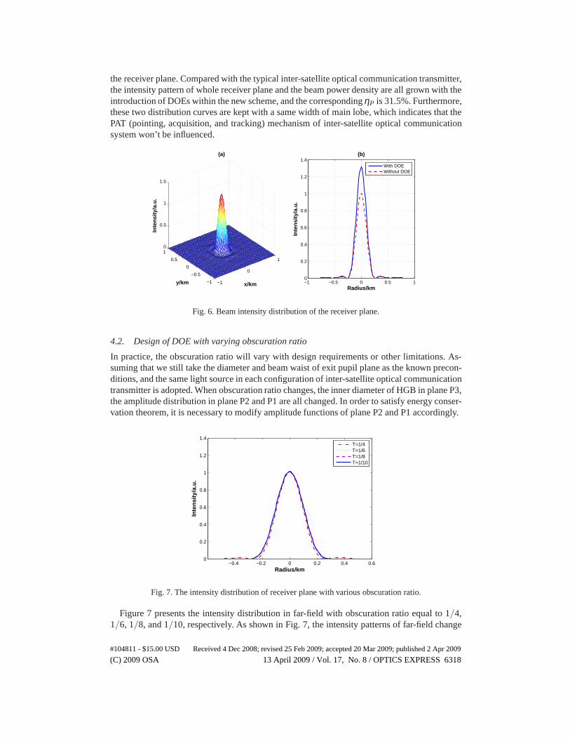
the receiver plane. Compared with the typical inter-satellite optical communication transmitter,the intensity pattern of whole receiver plane and the beam power density are all grown with theintroduction of DOEs within the new scheme, and the correspondingηP is 31.5%. Furthermore,these two distribution curves are kept with a same width of main lobe, which indicates that thePAT (pointing, acquisition, and tracking) mechanism of inter-satellite optical communicationsystem won’t be influenced.
−1
0
1
−1
−0.5
0
0.5
10
0.5
1
1.5
x/km
(a)
y/km
Inte
nsi
ty/a
.u.
−1 −0.5 0 0.5 10
0.2
0.4
0.6
0.8
1
1.2
1.4(b)
Radius/kmIn
ten
sity
/a.u
.
With DOEWithout DOE
Fig. 6. Beam intensity distribution of the receiver plane.
4.2. Design of DOE with varying obscuration ratio
In practice, the obscuration ratio will vary with design requirements or other limitations. As-suming that we still take the diameter and beam waist of exit pupil plane as the known precon-ditions, and the same light source in each configuration of inter-satellite optical communicationtransmitter is adopted. When obscuration ratio changes, the inner diameter of HGB in plane P3,the amplitude distribution in plane P2 and P1 are all changed. In order to satisfy energy conser-vation theorem, it is necessary to modify amplitude functions of plane P2 and P1 accordingly.
−0.4 −0.2 0 0.2 0.4 0.60
0.2
0.4
0.6
0.8
1
1.2
1.4
Radius/km
Inte
nsi
ty/a
.u.
T=1/4T=1/6T=1/8T=1/10
Fig. 7. The intensity distribution of receiver plane with various obscuration ratio.
Figure 7 presents the intensity distribution in far-field with obscuration ratio equal to 1/4,1/6, 1/8, and 1/10, respectively. As shown in Fig. 7, the intensity patternsof far-field change
#104811 - $15.00 USD Received 4 Dec 2008; revised 25 Feb 2009; accepted 20 Mar 2009; published 2 Apr 2009
(C) 2009 OSA 13 April 2009 / Vol. 17, No. 8 / OPTICS EXPRESS 6318

−0.4 −0.2 0 0.2 0.4 0.60
0.5
1
1.5
X: 0Y: 1.315
Radius/km
Inte
nsi
ty/a
.u.
(a) T=1/4
With DOEWithout DOE
−0.4 −0.2 0 0.2 0.4 0.60
0.5
1
1.5
X: 0Y: 1.137
Radius/km
Inte
nsi
ty/a
.u.
(b) T=1/6
With DOEWithout DOE
−0.4 −0.2 0 0.2 0.4 0.60
0.5
1
1.5
X: 0Y: 1.08
Radius/km
Inte
nsi
ty/a
.u.
(c) T=1/8
With DOEWithout DOE
−0.4 −0.2 0 0.2 0.4 0.60
0.5
1
1.5
X: 0Y: 1.055
Radius/km
Inte
nsi
ty/a
.u.
(d) T=1/10
With DOEWithout DOE
Fig. 8. The relative intensity distribution of receiver plane with various obscuration ratio.
little with the variation of obscuration ratio, which indicates that the improved configuration canbe suitable for various optical antennas. However, furthercomparison reveals that the smallerobscuration ratio, the lower side lobe of the intensity patterns. Obviously, This difference comesfrom the variation of peak valley width and amplitude coefficient in exit pupil plane, and theydon’t affect inter-satellite optical communication system.
Figure 8 shows the normalized intensity in far field with DOE and without DOE. The relativeincrement of peak energy will be reduced with the rising of obscuration ratioT. WhenT equalto 1/4, 1/6, 1/8, and 1/10, the correspondingηP are 31.5%, 13.7%, 8.1%, and 5.5%, respectively.
5. Conclusion
A novel scheme for improving beam quality of inter-satellite optical communication systemwas presented. Comparing to other methods, this scheme addsonly two diffractive lens intooptical path along optical axis, and a lossless output beam was obtained with the same mass,volume, and power consumption. The corresponding far field pattern were analyzed and dis-cussed for fixed and varying obscuration ratio, respectively. Numerical modelling with a fixedobscuration ratio of 1/4 demonstrated that the beam qualityof inter-satellite optical commu-nication system could be increased greatly. The results of numerical simulation with varyingobscuration ratio revealed that the intensity patterns of far-field change little with the variationof obscuration ratio, and the improved configuration can be suitable for various optical antenna.
Although, the realization of the method presented in this paper may be troubled by someuncertain factors. Whereas, this work can offer a useful reference for optimal design of opticaltelescope centrally obscured, and can also be a guidance forother applications of DOE insatellite optical communication system or other modern optical systems.
#104811 - $15.00 USD Received 4 Dec 2008; revised 25 Feb 2009; accepted 20 Mar 2009; published 2 Apr 2009
(C) 2009 OSA 13 April 2009 / Vol. 17, No. 8 / OPTICS EXPRESS 6319