appnote16164 p11 flashviacanbsl - infineon technologies
TRANSCRIPT
XC2000/XE166 Family16-bi t Microcontro l lers
AP16164Flash Progamming v ia CAN BSL (Bootstrap Loader)
Microcontrol lers
Appl icat ion NoteV1.0, 2009-10

Edition 2009-10Published byInfineon Technologies AG81726 Munich, Germany© 2009 Infineon Technologies AGAll Rights Reserved.
LEGAL DISCLAIMERTHE INFORMATION GIVEN IN THIS APPLICATION NOTE IS GIVEN AS A HINT FOR THE IMPLEMENTATION OF THE INFINEON TECHNOLOGIES COMPONENT ONLY AND SHALL NOT BE REGARDED AS ANY DESCRIPTION OR WARRANTY OF A CERTAIN FUNCTIONALITY, CONDITION OR QUALITY OF THE INFINEON TECHNOLOGIES COMPONENT. THE RECIPIENT OF THIS APPLICATION NOTE MUST VERIFY ANY FUNCTION DESCRIBED HEREIN IN THE REAL APPLICATION. INFINEON TECHNOLOGIES HEREBY DISCLAIMS ANY AND ALL WARRANTIES AND LIABILITIES OF ANY KIND (INCLUDING WITHOUT LIMITATION WARRANTIES OF NON-INFRINGEMENT OF INTELLECTUAL PROPERTY RIGHTS OF ANY THIRD PARTY) WITH RESPECT TO ANY AND ALL INFORMATION GIVEN IN THIS APPLICATION NOTE.
InformationFor further information on technology, delivery terms and conditions and prices, please contact the nearest Infineon Technologies Office (www.infineon.com).
WarningsDue to technical requirements, components may contain dangerous substances. For information on the types in question, please contact the nearest Infineon Technologies Office.Infineon Technologies components may be used in life-support devices or systems only with the express written approval of Infineon Technologies, if a failure of such components can reasonably be expected to cause the failure of that life-support device or system or to affect the safety or effectiveness of that device or system. Life support devices or systems are intended to be implanted in the human body or to support and/or maintain and sustain and/or protect human life. If they fail, it is reasonable to assume that the health of the user or other persons may be endangered.
Application Note 3 V1.0, 2009-10
AP16164Flash Progamming via CAN BSL (Bootstrap Loader)
Device1Revision History: V1.0 2009-10Previous Version(s):Page Subjects (major changes since last revision)– This is the first release …
We Listen to Your CommentsIs there any information in this document that you feel is wrong, unclear or missing? Your feedback will help us tocontinuously improve the quality of this document. Please send your proposal (including a reference to this document) to:[email protected]

AP16164Flash Progamming via CAN BSL (Bootstrap Loader)
Table of Contents
Application Note 4 V1.0, 2009-10
Table of Contents
1 Introduction and Requirements . . . . . . . . . . . . . . . . . . . . . . . . . . . . . . . . . . . . . . . . . . . . . . . . . . . . 51.1 Hardware Requirements . . . . . . . . . . . . . . . . . . . . . . . . . . . . . . . . . . . . . . . . . . . . . . . . . . . . . . . . . . . . 5
2 CAN BSL (Bootstrap Loader) in the XC2000/XE166 . . . . . . . . . . . . . . . . . . . . . . . . . . . . . . . . . . . . 62.1 Entering the CAN BSL . . . . . . . . . . . . . . . . . . . . . . . . . . . . . . . . . . . . . . . . . . . . . . . . . . . . . . . . . . . . . 72.2 Loading the User Code . . . . . . . . . . . . . . . . . . . . . . . . . . . . . . . . . . . . . . . . . . . . . . . . . . . . . . . . . . . . . 82.3 Exiting CAN BSL . . . . . . . . . . . . . . . . . . . . . . . . . . . . . . . . . . . . . . . . . . . . . . . . . . . . . . . . . . . . . . . . . . 8
3 General System Description . . . . . . . . . . . . . . . . . . . . . . . . . . . . . . . . . . . . . . . . . . . . . . . . . . . . . . . 93.1 Master Board . . . . . . . . . . . . . . . . . . . . . . . . . . . . . . . . . . . . . . . . . . . . . . . . . . . . . . . . . . . . . . . . . . . 113.1.1 Transmitter Program (Project File: CAN_BSLMaster) . . . . . . . . . . . . . . . . . . . . . . . . . . . . . . . . . . . 123.1.2 Receiver Program (Project File: CAN_Loader) . . . . . . . . . . . . . . . . . . . . . . . . . . . . . . . . . . . . . . . . 133.1.3 Application Software (Project File: MainApplication_XE16x) . . . . . . . . . . . . . . . . . . . . . . . . . . . . . . 133.2 Slave Board . . . . . . . . . . . . . . . . . . . . . . . . . . . . . . . . . . . . . . . . . . . . . . . . . . . . . . . . . . . . . . . . . . . . 14
4 XC2000/XE166 Internal Flash Programming . . . . . . . . . . . . . . . . . . . . . . . . . . . . . . . . . . . . . . . . . 154.1 The Internal Flash Memory . . . . . . . . . . . . . . . . . . . . . . . . . . . . . . . . . . . . . . . . . . . . . . . . . . . . . . . . . 154.2 Flash Driver . . . . . . . . . . . . . . . . . . . . . . . . . . . . . . . . . . . . . . . . . . . . . . . . . . . . . . . . . . . . . . . . . . . . 16
5 Communication Protocol . . . . . . . . . . . . . . . . . . . . . . . . . . . . . . . . . . . . . . . . . . . . . . . . . . . . . . . . 175.1 Process Commands . . . . . . . . . . . . . . . . . . . . . . . . . . . . . . . . . . . . . . . . . . . . . . . . . . . . . . . . . . . . . . 175.1.1 Sector Erasing Operation . . . . . . . . . . . . . . . . . . . . . . . . . . . . . . . . . . . . . . . . . . . . . . . . . . . . . . . . 175.1.2 Flash Page Programming Operation . . . . . . . . . . . . . . . . . . . . . . . . . . . . . . . . . . . . . . . . . . . . . . . . 175.1.3 Application Reset for the Standard Start . . . . . . . . . . . . . . . . . . . . . . . . . . . . . . . . . . . . . . . . . . . . . 185.1.4 Application Reset for the CAN BSL Mode . . . . . . . . . . . . . . . . . . . . . . . . . . . . . . . . . . . . . . . . . . . . 185.1.5 Download an Application Example Code . . . . . . . . . . . . . . . . . . . . . . . . . . . . . . . . . . . . . . . . . . . . . 18
6 Using this Application Note . . . . . . . . . . . . . . . . . . . . . . . . . . . . . . . . . . . . . . . . . . . . . . . . . . . . . . . 19
7 Running this Application Note without HiTOP5 . . . . . . . . . . . . . . . . . . . . . . . . . . . . . . . . . . . . . . 21
8 Appendix . . . . . . . . . . . . . . . . . . . . . . . . . . . . . . . . . . . . . . . . . . . . . . . . . . . . . . . . . . . . . . . . . . . . . . 238.1 Hardware Bugs . . . . . . . . . . . . . . . . . . . . . . . . . . . . . . . . . . . . . . . . . . . . . . . . . . . . . . . . . . . . . . . . . . 238.2 Hex Code . . . . . . . . . . . . . . . . . . . . . . . . . . . . . . . . . . . . . . . . . . . . . . . . . . . . . . . . . . . . . . . . . . . . . . 248.3 XC2000/XE166 Easy Board V1.1 . . . . . . . . . . . . . . . . . . . . . . . . . . . . . . . . . . . . . . . . . . . . . . . . . . . . 248.4 XC2000/XE166 Easy Board V2.0 and V3.0 . . . . . . . . . . . . . . . . . . . . . . . . . . . . . . . . . . . . . . . . . . . . 258.5 Script File: AppNote16164_CAN_BSL.scm . . . . . . . . . . . . . . . . . . . . . . . . . . . . . . . . . . . . . . . . . . . . 25

AP16164Flash Progamming via CAN BSL (Bootstrap Loader)
Introduction and Requirements
1 Introduction and RequirementsThe Infineon XC2000/XE166 Family of devices (Table 1) include a built-in CAN Bootstrap Loader (CAN BSL).Using the CAN BSL, it is possible to load code or data into the internal PSRAM of the device via the MultiCANinterface. What is not available however, is a built-in mechanism for internal flash programming.This application note will demonstrate how to program the internal flash of XC2000/XE166 devices via the CANBSL.
The example described makes use of the Tasking compiler tool. However to debug and download readable Hexfiles, it is possible to directly use the Hitex tool (HiTOP53) included in the Infineon UConnect-CAN XE164 kit.
1.1 Hardware RequirementsThe following hardware is required for the example described in this application note:• Two XC2000/XE16x boards
– If a compiler and debug tool are already installed, the application software can run in any two Infineon Easy Kit boards equipped with a target device listed in Table 1. The Infineon UConnect-CAN XE164 comes with a free compiler and debug tool development suite (a size limited evaluation version). In the example described in this document, the UConnect-CAN XE164 is the ’host’ board, while the XE167FM EasyKit with active CAN BSL, acts as the ’slave’ board.
• Terminal program; MTTTY for example. – This is used to give commands to the host and to display actual states and error messages.
• CAN bus cable• CAN Analyzer tool (optional)
Table 1 XC2000/XE166XE166 Derivative with CAN BSL Derivative PackageXC228x, XC228xM PG-LQFP-144XC226x, XC226xM, XC226xN PG-LQFP-100XC238x, XC238xA PG-LQFP-144XC236x, XC236xA, XC236xB PG-LQFP-100XC233xA, XC233xB PG-LQFP-64XC2786X, XC2785X PG-LQFP-144XC2766X, XC2765X, XC2764X PG-LQFP-100XE167, XE167M PG-LQFP-144XE164, XE164M, XE164N PG-LQFP-100XE162M, XE162N PG-LQFP-64XE169H, XC229xH PG-LQFP-176 (coming soon)XE167H, XC228xH PG-LQFP-144 (coming soon)
Application Note 5 V1.0, 2009-10

AP16164Flash Progamming via CAN BSL (Bootstrap Loader)
CAN BSL (Bootstrap Loader) in the XC2000/XE166
2 CAN BSL (Bootstrap Loader) in the XC2000/XE166A built-in CAN Bootstrap Loader (BSL) is implemented in the Infineon XC2000/XE166 family of devices. CAN BSL provides a mechanism to load program code or data via the MultiCAN module into the PSRAM of adevice, and to start executing the loaded code from address E0 0000H (address of the first transmitted byte). The CAN BSL is an integrated mechanism that can be selected via port configuration during a system start aftera Power-on Reset, or through write configuration registers and trigger then a software reset. For more details,please see Chapter 2.1.The CAN BSL uses a CAN node 0 interface and configures the MultiCAN module to the baud rate of the hostdevice. Once communication has been established, the BSL receives a defined number of messages (the number definedin the host) for downloading the code or data. The received code or data is sequentially written to the PSRAM.Once the download has finished, the program code that has been loaded is executed and the BSL is terminated. The complete load sequence is based on the following three CAN standard frames:• Initialization Frame
– sent by the external host to XC2000/XE166• Acknowledge Frame
– sent by the XC2000/XE166 to the external host• Data Frames
– sent by the external host to the XC2000/XE166The initialization frame is used in the XC2000/XE166 device for baud rate detection. After successful baud rate detection, the XC2000/XE166 reports to the external host via the acknowledge frame. Data frames can then be transmitted from the host to the XC2000/XE166 device. Data frames are alwaystransmitted in 8 bytes.
Table 2 CAN Bootstrap Loader FramesFrame Type Parameter Description
Initialization Frame Identifier 11-bit, don’t care DLC=8Data byte 0-1 0x5555
Data byte 2-3 acknowledge message identifier ACK_ID(use bits [13:0], bit 13=IDE)
Data byte 4-5 Data Message Count MSG_CNTMust be <= 1FE0H for 64KBytes SPRAM, see Chapter 2.2For example; MSG_CNT=0x200 for 0000H-0FFFH (4KBytes)
Data byte 6-7 Data Message Identifier MSG_ID Acknowledge Frame
Identifier ACK_ID as received bytes [3:2] of the Initialization FrameDLC=4Data byte 0-1 BTR register value in XC2000
Data byte 0-1 Data bytes [3.2] of the Initialization Frame Data Frame Identifier Data Message Identifier MSG_ID as sent by data bytes [7:6] of the
Initialization FrameDLC=8Data byte 0-7 Data Bytes, assigned to increasing destination (PSRAM) addresses
Application Note 6 V1.0, 2009-10

AP16164Flash Progamming via CAN BSL (Bootstrap Loader)
CAN BSL (Bootstrap Loader) in the XC2000/XE166
2.1 Entering the CAN BSLThe XC2000/XE166 enters CAN BSL mode, when the CAN BSL mode is selected within the startup configurationupon a reset signal. Bit field HWCFG=xxx101b in register STSTAT indicates the CAN BSL mode.Bit field HWCFG is updated either by:• Hardware: with a pull-up/down resistor when the configuration pins P10.2-0 has the value 101b at Power-On,
or after an Internal Application Reset.• Software: when 000xx101b is written into bit field SWRSTCON.SWCFG and an Application Reset is triggered
with SWRSTCON.SWBOOT=1 (Software Boot configuration selection).Note: To directly generate a software reset request trigger, either use the instruction SRST, or set bit
SWRSTCON.SWRSTREQ = 1.
Notes1. Because of a hardware bug (see Chapter 8.1 ’RESET_X.002’) the bit field HWCFG in the register STSTAT is
unable to indicate the actual start-up mode selected in early XC2000/XE166 devices. This bug is fixed in the M-, N-, 5-, H- series of devices (see Table 1).
2. The type of software reset should be configured first (RSTCON0.SW = 1xb)3. The type of instruction (SRST) is defined via bit field RSTCON0.CPU.4. 01b is reserved. It can not be configured for RSTCON0.CPU or RSTCON0.SW. 5. For example code, please see Chapter 8.2.
The CAN BSL initializes the MultiCAN as follows:• CAN node 0 of the MultiCAN module is used.• Message Object 0 (MO0) is configured as Receive Object to receive the initialization and data frame.• Message Object 1 (MO1) is configured as Transmit Object to transmit the acknowledge frame.• CAN input/output pins: P2.6=RxDC0 and P2.5=TxDC0. RXSEL=0x0003.• In CAN BSL the system clock is provided by OSC_HP circuitry (supplied by a external oscillator or an external
clock source). fSYS:=fOSC is selected by SYSCON0.CLKSEL=01b.
During the initialization phase:• The Bit Timing Mode is used for baud rate detection and analysis of the bit timing.• The Analyzer Mode is used to monitor the CAN frame without active participation.• All Acceptance Mask bits of the receive object MO0 are OFF.
After the initialization phase: • The Analyzer Mode is switched off. The bit timing mode for CAN node 0 does not change.• BTR is set with the calculated value and SJW=01b. • All Acceptance Mask bits of the receive object MO0 are ON: CAN_MOAMR0=01FFF,FFFFH.
Application Note 7 V1.0, 2009-10

AP16164Flash Progamming via CAN BSL (Bootstrap Loader)
CAN BSL (Bootstrap Loader) in the XC2000/XE166
2.2 Loading the User CodeThe sequence for loading the user code is as follows:• The code is downloaded starting at address 0E0,0000H. Consecutive data bytes are stored at incrementing
addresses.• After receipt of the last CAN data frame, the Bootstrap Loader sequence is finished and executes a jump to
address 0E0,0000H.• XC2000/XE166 has 64K PSRAM (0E0,0000H - 0E0,FFFFH), but the last 255 bytes are dedicated to the on-
chip firmware; i.e. If code or data is downloaded to that area it will be overwritten afterwards by the on-chip firmware. Therefore the maximum CAN message count (MSG_CNT) in the initialization frame is 8192-32.
2.3 Exiting CAN BSLAfter the Bootstrap Loader has been activated, the Watchdog Timer and the Debug system are disabled. The Debug system and Watchdog Timer are released automatically when the BSL terminates after havingreceived a set number of messages from the host (the number of messages is defined via a variable in the host). The CAN BSL is also aborted after a Power On Reset, if the non-BSL port configuration has been used (seeChapter 2.1).
Application Note 8 V1.0, 2009-10

AP16164Flash Progamming via CAN BSL (Bootstrap Loader)
General System Description
3 General System DescriptionAs host device, the UConnect-CAN XE164 is connected to a PC via a JTAG/UART interface. The XE164 shouldbe in Standard Start mode.As slave device, the XE167FM EasyKit is connected to the host via a CAN interface. The XE167FM should be inactive CAN BSL mode.This application note describes software for the host board. The host device takes control of the slave device viathe CAN bus, while commands are received and process status changes are reported via the JTAG/UARTinterface to the PC COM port.
Figure 1 System Overview
There are three different pieces of code (three Tasking projects) for the host device associated with this applicationnote:• Transmitter Program: CAN_BSLMaster
– Initializes the MultiCAN module in the host device (including the CAN transmit pins and configuring the initialization frame) to establish the communication with the slave.
– Defines a port pin to signal the process of starting, data transmission, and termination of the download sequence.
– Initializes the USIC module and configures U0C0 as the ASC interface to communicate with the PC COM port.
– Code should be compiled for the location of the internal flash at address 0C1,0000H.• Receiver Program: CAN_Loader
– Must first be downloaded to the slave device in active CAN BSL mode. After a successful download, this code will be executed.
– It contains commands for a ‘handshake’ between the host and slave devices.– Defines a port pin to signal the process status on the slave board. – Code should be compiled for the location of the internal PSRAM, at address 0E0,0000H.
Uconnect XE164Host board
(standard start mode)
Easy Kit XE167MSlave board
CAN BSL mode
CAN BUS
PC
Download Hex files and report status information via JTAG/UART
US
B
Transmit upgrade application SW via the CAN bus in standard start mode
Receive upgrade application SW from CAN bus in CAN BSL mode and program then into the internal flash
CAN node 0 CAN node 0
JTAG/ASC
Application Note 9 V1.0, 2009-10
AP16164Flash Progamming via CAN BSL (Bootstrap Loader)
General System Description
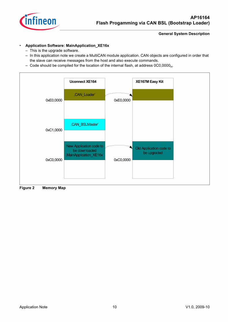
• Application Software: MainApplication_XE16x– This is the upgrade software.– In this application note we create a MultiCAN module application. CAN objects are configured in order that
the slave can receive messages from the host and also execute commands.– Code should be compiled for the location of the internal flash, at address 0C0,0000H.
Figure 2 Memory Map
Uconnect XE164 XE167M Easy Kit
0xE0,0000‚CAN_Loader’
0xC1,0000‚CAN_BSLMaster’
0xC0,0000
New Application code to be downloaded
‚MainApplication_XE16x’0xC0,0000
Old Application code to be upgraded
0xE0,0000
Application Note 10 V1.0, 2009-10

AP16164Flash Progamming via CAN BSL (Bootstrap Loader)
General System Description
3.1 Master BoardOne method of connecting a PC to a microcontroller is to use the PC COM port to download a generated hex fileinto the microcontroller. In this case the microcontroller must be in active ASC BSL mode. Infineon providesfreeware tools, such as Memtool and Minimon, to support on-chip flash programming.Another method is to use the JTAG interface. In this application example, UConnect-CAN XE164 is used as a’USB-to-CAN bridge’ to download and program the XC2000/XE166 internal flash from the PC.The UConnect-CAN XE164 is a low cost USB stick providing full evaluation capability for the new XE164microcontroller. For detailed information about the XE164 UConnect stick, please refer to www.infineon.com.
Figure 3 UConnect_CAN XE164
At one end of the UConnect-CAN XE164 is the USB connector. Inside there is an FT2232 chip with two USBchannels. One channel is for the JTAG interface supporting the OCDS feature, while the other channel acts as thevirtual COM port. This serial channel is connected to pins P7.3 and P7.4 of the XE164 USIC module (Tx and Rxof the U0C0 ASC interface).To start the serial interface either Windows HyperTerminal software, or freeware like MTTTY, can be used. The HiTOP53-UConnect-XE164 can be used for debugging. Tools can be directly installed from the UConnect-CAN XE164 kit’s CD.On the other side of the UConnect stick is the Target Connector (Figure 3). XE164 port pin P2.6 (CAN0_Rx) andP2.5 (CAN0_Tx) are connected to CAN transceiver. To start this application SW pin CANL and pin CANH on host board UConnect-CAN XE164 and slave boardXE167FM EasyKit (see Figure 5) must be connected together.
USB Connector
Debug LED (red)
P2.7 LED (blue)P2.8 LED (blue)
Power LED (green)
Target Connector
15 13 11 9 7 5 3 1
16 14 12 10 8 6 4 2
CANH P0.4 P0.5 P0.3 P0.2 P5.9 P15.0 GND
CANL P0.7 P0.6 P0.0 P0.1 P5.8 P5.0 +5VPin/Signal on the target connector
Application Note 11 V1.0, 2009-10

AP16164Flash Progamming via CAN BSL (Bootstrap Loader)
General System Description
3.1.1 Transmitter Program (Project File: CAN_BSLMaster)The Transmitter program is the main program for the host board. It controls the interface between the developmentenvironment (the PC) and the CAN bus.The UConnect-CAN XE164 board has an 8MHz quartz crystal for the input oscillator circuit. At startup, through afunction call, the system frequency is changed to 40MHz via the internal PLL configuration and Pin 2.8 is definedfor system clock output.The Transmitter program uses the communication peripherals of the microcontroller: • The USIC0 channel 0 is configured as UART (19200Baud) to communicate serially to the HyperTerminal on
the PC. • The MultiCAN module CAN node 0 (Rx=P2.6, Tx=P2.5) is configured with 200Kbaud to communicate to the
slave.• Message Object 0 is defined as Receive object.• Message Object 1 is defined as Transmit object. In the CAN initialization routine the Initialization Frame is configured as per the description in Table 2. No interruptis defined in the CAN or USIC module (polling system).After initialization, the download from host to slave begins.
Figure 4 Data Communication on the CAN Bus
After a successfully download sequence, which can be seen with reporting on the terminal program communicatedvia the PC COM port, several commands can be selected to control the handshake between the host device andthe slave (see Chapter 5 for details).
PC
Slave BoardMaster Board
CAN Int. Frame
CAN Ack. Frame
‚CAN_Loader’
CAN_BSL_EXECUTION
COMMUNICATIONVia CAN
‚CAN_Loader’
Command ‚a’,‚e’,’c’,‚r’
Status/Error
(UART)
‚MainApplication_XE16x’
MAIN_EXECUTION
COMMUNICATIONVia CAN
CSP=0xC1‚RUN’
(JTAG)
CAN BSL PROCESS
Command ’c’,‚r’
Status/Error
(UART)
‚CAN_BSLMaster’
Application Note 12 V1.0, 2009-10

AP16164Flash Progamming via CAN BSL (Bootstrap Loader)
General System Description
3.1.2 Receiver Program (Project File: CAN_Loader)The Receiver program is a piece of code for the slave device. It’s role is to program the application program(received via the CAN bus) into the internal flash. The Receiver program must be downloaded into SPRAM in CANBSL mode.The built-in CAN BSL only provides a mechanism to load code via the CAN bus into the PSRAM. To program theinternal flash of XC2000/XE166 devices, the flash driver (software code of flash command sequences, such as’erase’ and ’program’ for example), must be implemented and included in the CAN_Loader project file and bedownloaded to the device. The Receiver program is composed of two main parts:• Flash Driver
– all the flash programming routines used to program the flash memory.• Communication Sequence
– between the host and the slave, including signal handling (the commands of the CAN message object) for the handshake.
Port 10 is defined as GPIO output, to signal a successful download to the slave board.Once in CAN BSL mode on the slave board (i.e. after a Power-on Reset), the ’CAN_Loader.hex’ code can bedownloaded to the slave PSRAM by executing the master Transmitter program ’CAN_BSLMaster.hex’, controlledby the debug tool HiTOP53-UConnect-XE164. 4Kbytes are currently defined for the Receiver program ’CAN_Loader.hex’ in this application (0E0,0000H -0E0,0FFFH).Blinking LEDs on the slave board indicate that the CAN BSL mode has been terminated and that the codedownloaded to PSRAM is executing. The software then checks the receive information of the CAN frame in cyclepolling (the MultiCAN module and system clock are not reconfigured and the Tx/Rx message object and the baudrate parameter are not changed), while the software waits for a CAN message command from the host.
3.1.3 Application Software (Project File: MainApplication_XE16x)An application program is required to upgrade the internal flash of the device. This application note includes asimple application program (MainAplication_XE16x), which provides the functionality to support communicationwith a host board via the CAN interface.The example code is intended to be straightforward. Pin P10.2 is defined as GPIO output pin and starting theapplication program lights up its LED. The code also sets up the MultiCAN peripheral so that it can receive CANmessages. In the current version only two commands are implemented: • A command to generate an Application Reset for Internal Standard Start (start address 0C0,0000H).• A command to generate an Application Reset for the CAN BSL mode.
Application Note 13 V1.0, 2009-10

AP16164Flash Progamming via CAN BSL (Bootstrap Loader)
General System Description
3.2 Slave BoardAny Infineon Easy Kit equipped with a target device listed in Table 1, can be used as a slave board. The following figure shows the layout overview of the XE167FM EasyKit. For further details, please refer to theBoard User’s Manual.
Figure 5 XE167FM Layout Overview
Notes1. CAN BSL can not be directly used on XC2000/XE166XE166 Easy Board (v1.1), because P2.5 and P2.6 are
not connected to the CAN SUB-9 connector (see Chapter 8.3).2. CAN BSL can not be directly started on XC2000/XE166 Easy Board (V1, V2 and V3), because the quartz
crystal NX8045GB needs a longer rise time (ca. 1ms) than the wait-time in the built-in RoomCode (see Chapter 8.1).
The CAN BSL requires a ‘point-to-point’ connection with the host; i.e. the XC2000/XE166 must be the only CANnode connected to the network. A system clock with at least 4MHz is required for the CAN Bootstrap Loader operation. The XC2000/XE167 has a 1:1 direct drive clock in the CAN BSL mode. The following baud rates have been tested:• With ceramic resonator (8MHz): 100Kbaud, 200Kbaud, 500Kbaud, 1Mbaud• With internal oscillator (nominal value 10MHz): 100kbaud, 200kbaud, 400kbaud (500kbaud fails),
– for example; CAN BSL mode is started by execution of the software workaround directly from the internal flash (see Chapter 8.2).
S102
ON
OFF
CANH
CANL
CAN BSL mode
ON
OFF
ASC BSL mode
8MHzQuarz
UART/JTAG
Application Note 14 V1.0, 2009-10

AP16164Flash Progamming via CAN BSL (Bootstrap Loader)
XC2000/XE166 Internal Flash Programming
4 XC2000/XE166 Internal Flash ProgrammingThis chapter is divided into two sections:• The Internal Flash Memory• Flash Driver
4.1 The Internal Flash MemoryThe XC2000/XE166 M-series devices (see Table 1) have up to 832Kbytes of on-chip flash memory.The on-chip flash memory consists of up to four independent flash units (maximum 256Kbtes/unit). All flash unitscan be used for both code and data storage. Each unit is built up from 4-KByte physical sectors. Each sector can be separately erased and programmed (inblocks of 128 bytes). The flash memory supports read and write protection, where protection is implemented by logical sector. Each memory unit consists up to 12 logical sectors (4K, 12K, 16K, 32K, 60K, 64K).The ‘erase’ operation can be used on a page (128 bytes) or a physical sector (32*128 bytes). The ’program’operation is applied pnly per page (128 bytes).Read protection always globally covers the whole flash memory range (i.e. all four flash units). The bit fieldIMB_FSR_PROT.RPRO indicates the status.Write protection can be globally enabled when Read protection is applied, or it can be specified for each logicalsector (4x12) in each flash memory area. Registers IMB_PROCON0...3 (bit S12U…S0U) indicate the status.
Figure 6 Logical Sectors in XC2000M/XE167FM (256K Area)
Application Note 15 V1.0, 2009-10

AP16164Flash Progamming via CAN BSL (Bootstrap Loader)
XC2000/XE166 Internal Flash Programming
Note: The XC2000/XE167 devices all have different flash sizes and different allocations of logical sectors. For more details about flash memory size, location, protection and operating modes, please refer to the appropriate User’s Manual or Data Sheet.
4.2 Flash DriverTo perform a ’program’ operation on the flash memory, it is necessary to write some command sequences. Thefollowing table gives the possible operations and their command definitions as used in this application note:
Notes1. PA=Page Address; WD=Write Data; SA=Sector Address2. All of the command sequences given above, except for Load Page Word, set the BUSY flag for the duration
of their operation. Software must check the BUSY bit after the command instructions. The main part of SW CAN_Loader implements flash routines which provide the flash functionality listed in thetable above (Table 3). However the user can still add other features as desired, such as the ’enable readprotection’ operation, or ’disable read protection’ for example.
Table 3 Command Sequence Definitions (Programming and Erasing)Cycle 1 2 3 Flag BUSY
Erase Page MOV xxAAH, xx80H MOV xx54H, xxAAH MOV PA, xx03H YesEnter Page MOV xxAAH, xx50H MOV PA, xxAAH YesLoad Page Word MOV xxF2H, WD -Program Page MOV xxAAH, xxA0H MOV xx5AH, xxAAH YesErase Sector MOV xxAAH, xx80H MOV xx54H, xxAAH MOV SA, xx33H Yes
Application Note 16 V1.0, 2009-10
AP16164Flash Progamming via CAN BSL (Bootstrap Loader)
Communication Protocol
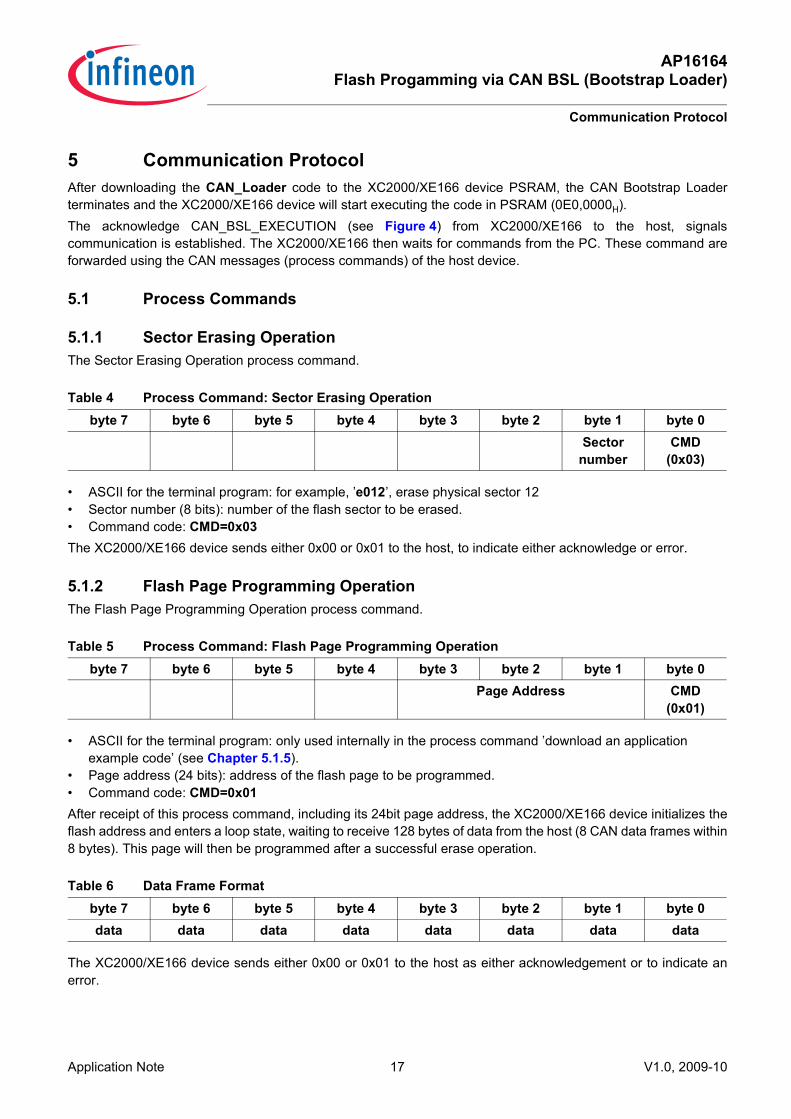
5 Communication Protocol After downloading the CAN_Loader code to the XC2000/XE166 device PSRAM, the CAN Bootstrap Loaderterminates and the XC2000/XE166 device will start executing the code in PSRAM (0E0,0000H). The acknowledge CAN_BSL_EXECUTION (see Figure 4) from XC2000/XE166 to the host, signalscommunication is established. The XC2000/XE166 then waits for commands from the PC. These command areforwarded using the CAN messages (process commands) of the host device.
5.1 Process Commands
5.1.1 Sector Erasing OperationThe Sector Erasing Operation process command.
• ASCII for the terminal program: for example, ’e012’, erase physical sector 12• Sector number (8 bits): number of the flash sector to be erased. • Command code: CMD=0x03The XC2000/XE166 device sends either 0x00 or 0x01 to the host, to indicate either acknowledge or error.
5.1.2 Flash Page Programming OperationThe Flash Page Programming Operation process command.
• ASCII for the terminal program: only used internally in the process command ’download an application example code’ (see Chapter 5.1.5).
• Page address (24 bits): address of the flash page to be programmed. • Command code: CMD=0x01After receipt of this process command, including its 24bit page address, the XC2000/XE166 device initializes theflash address and enters a loop state, waiting to receive 128 bytes of data from the host (8 CAN data frames within8 bytes). This page will then be programmed after a successful erase operation.
The XC2000/XE166 device sends either 0x00 or 0x01 to the host as either acknowledgement or to indicate anerror.
Table 4 Process Command: Sector Erasing Operationbyte 7 byte 6 byte 5 byte 4 byte 3 byte 2 byte 1 byte 0
Sector number
CMD(0x03)
Table 5 Process Command: Flash Page Programming Operationbyte 7 byte 6 byte 5 byte 4 byte 3 byte 2 byte 1 byte 0
Page Address CMD(0x01)
Table 6 Data Frame Formatbyte 7 byte 6 byte 5 byte 4 byte 3 byte 2 byte 1 byte 0data data data data data data data data
Application Note 17 V1.0, 2009-10
AP16164Flash Progamming via CAN BSL (Bootstrap Loader)
Communication Protocol
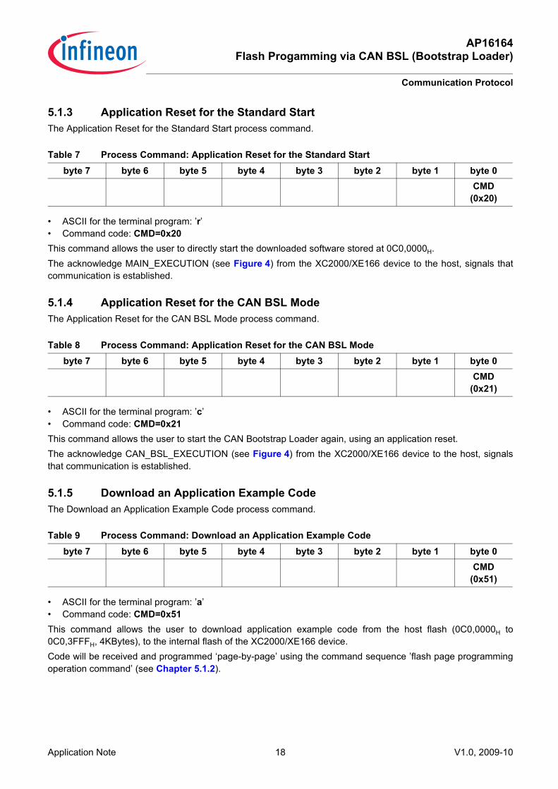
5.1.3 Application Reset for the Standard StartThe Application Reset for the Standard Start process command.
• ASCII for the terminal program: ’r’• Command code: CMD=0x20This command allows the user to directly start the downloaded software stored at 0C0,0000H. The acknowledge MAIN_EXECUTION (see Figure 4) from the XC2000/XE166 device to the host, signals thatcommunication is established.
5.1.4 Application Reset for the CAN BSL ModeThe Application Reset for the CAN BSL Mode process command.
• ASCII for the terminal program: ’c’• Command code: CMD=0x21This command allows the user to start the CAN Bootstrap Loader again, using an application reset.The acknowledge CAN_BSL_EXECUTION (see Figure 4) from the XC2000/XE166 device to the host, signalsthat communication is established.
5.1.5 Download an Application Example CodeThe Download an Application Example Code process command.
• ASCII for the terminal program: ’a’• Command code: CMD=0x51This command allows the user to download application example code from the host flash (0C0,0000H to0C0,3FFFH, 4KBytes), to the internal flash of the XC2000/XE166 device. Code will be received and programmed ‘page-by-page’ using the command sequence ’flash page programmingoperation command’ (see Chapter 5.1.2).
Table 7 Process Command: Application Reset for the Standard Startbyte 7 byte 6 byte 5 byte 4 byte 3 byte 2 byte 1 byte 0
CMD(0x20)
Table 8 Process Command: Application Reset for the CAN BSL Modebyte 7 byte 6 byte 5 byte 4 byte 3 byte 2 byte 1 byte 0
CMD(0x21)
Table 9 Process Command: Download an Application Example Codebyte 7 byte 6 byte 5 byte 4 byte 3 byte 2 byte 1 byte 0
CMD(0x51)
Application Note 18 V1.0, 2009-10

AP16164Flash Progamming via CAN BSL (Bootstrap Loader)
Using this Application Note
6 Using this Application NoteTo use this application note will require one UConnect-CAN XE164 to act as host and one XE167FM EasyKit toact as slave. All hardware should be connected as shown in Figure 1. • Insert the USB connector of the UConnect stick to the PC USB port.• Connect the target connector CAN pins of the UConnect stick with the CAN pins on the Easy board (Figure 3
and Figure 5).The two boards have to been configured first:• Set the slave board to active CAN BSL mode:
– DIP switch S102 in Figure 5 P10.0-P10.1-P10.2-P10.3-/TRST)=OFF-ON-OFF-xx-ON(1-0-1-x-1)– Make a Power-on Reset
Notes1. Because of a hardware bug (BSL_CAN_X.001 - see Chapter 8.1), the CAN BSL can not be directly started
on the XE167FM EasyKit. The quartz crystal NX8045GB on the board needs to be changed with an 8MHz ceramic resonator, OR -
2. Alternatively, if Memtool is available on the PC and your board can be started in the ASC BSL mode, the board does not have to be changed. Instead Memtool can be used to program the instructions of SW workaround into the flash of the slave board first. Then start it in the Standard Start Mode via a Power-on Reset. This is the software workaround for the hardware bug BSL_CAN_X.001. A hex file is provided in Chapter 8.2.
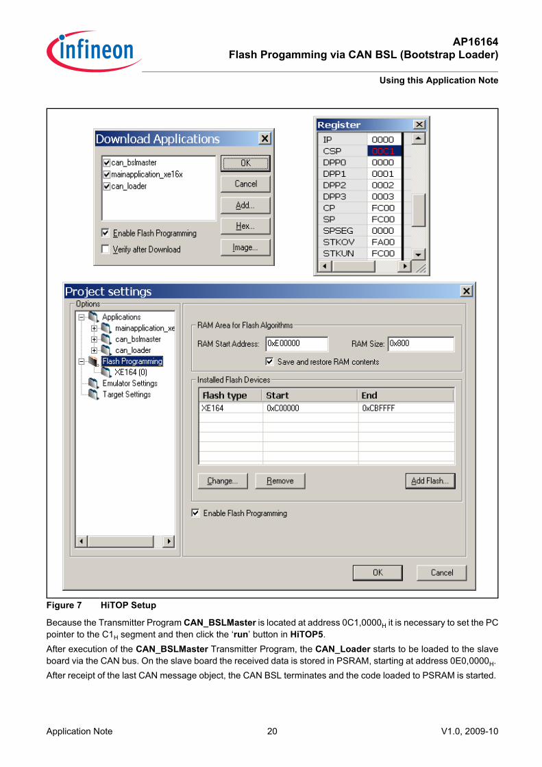
After all of the steps above have been successfully completed, the tools can be started:• The HyperTerminal program (19200Baud) • Hitex debug tool HiTOP53-UConnect-XE164The three pieces of code (two located in the flash and one located in the PSRAM) should first be programmed inthe XE164 of the UConnect kit. Because the HiTOP5 places its own flash driver in the PSRAM at address 0E0,0000H, the PSRAM codeCAN_Loader must be downloaded in the final stages to avoid being overwritten by the HiTOP5 software (seeFigure 7).
Application Note 19 V1.0, 2009-10
AP16164Flash Progamming via CAN BSL (Bootstrap Loader)
Using this Application Note
Figure 7 HiTOP Setup
Because the Transmitter Program CAN_BSLMaster is located at address 0C1,0000H it is necessary to set the PCpointer to the C1H segment and then click the ‘run’ button in HiTOP5.After execution of the CAN_BSLMaster Transmitter Program, the CAN_Loader starts to be loaded to the slaveboard via the CAN bus. On the slave board the received data is stored in PSRAM, starting at address 0E0,0000H. After receipt of the last CAN message object, the CAN BSL terminates and the code loaded to PSRAM is started.
Application Note 20 V1.0, 2009-10
AP16164Flash Progamming via CAN BSL (Bootstrap Loader)
Running this Application Note without HiTOP5
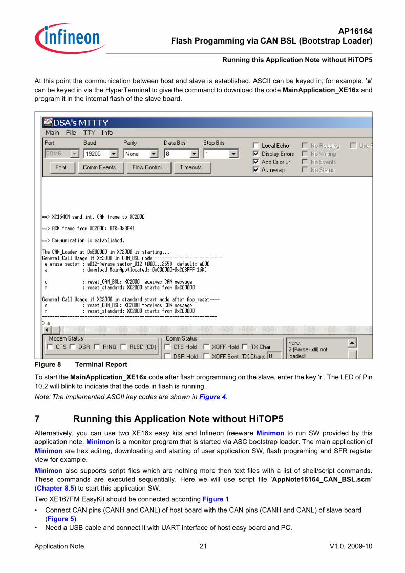
At this point the communication between host and slave is established. ASCII can be keyed in; for example, ’a’can be keyed in via the HyperTerminal to give the command to download the code MainApplication_XE16x andprogram it in the internal flash of the slave board.
Figure 8 Terminal Report
To start the MainApplication_XE16x code after flash programming on the slave, enter the key ‘r’. The LED of Pin10.2 will blink to indicate that the code in flash is running.Note: The implemented ASCII key codes are shown in Figure 4.
7 Running this Application Note without HiTOP5Alternatively, you can use two XE16x easy kits and Infineon freeware Minimon to run SW provided by thisapplication note. Minimon is a monitor program that is started via ASC bootstrap loader. The main application ofMinimon are hex editing, downloading and starting of user application SW, flash programing and SFR registerview for example. Minimon also supports script files which are nothing more then text files with a list of shell/script commands.These commands are executed sequentially. Here we will use script file ’AppNote16164_CAN_BSL.scm’(Chapter 8.5) to start this application SW.Two XE167FM EasyKit should be connected according Figure 1.• Connect CAN pins (CANH and CANL) of host board with the CAN pins (CANH and CANL) of slave board
(Figure 5).• Need a USB cable and connect it with UART interface of host easy board and PC.
Application Note 21 V1.0, 2009-10

AP16164Flash Progamming via CAN BSL (Bootstrap Loader)
Running this Application Note without HiTOP5
The two boards have to been configured first:• Set the slave board to active CAN BSL mode:
– DIP switch S102 in Figure 5 P10.0-P10.1-P10.2-P10.3-/TRST)=OFF-ON-OFF-xx-ON(1-0-1-x-1)– Make a Power-on Reset
• Set the host board to active ASC BSL mode:– DIP switch S102 in Figure 5 P10.0-P10.1-P10.2-P10.3-/TRST)=ON-OFF-OFF-xx-ON(0-1-1-x-1)– Make a Power-on Reset
After all of the steps above have been successfully completed, the tool Minimon can be started.• Select ’XC2000’ in the controller type under menu ’Target/Configuration’.• Select the activated virtual COM port and configure ’19200baud’ under menu ’Settings/Communication’.• Select ASCII text mode under menu ’Settings/Terminal Settings’.• Assign the script file ’AppNote16164_CAN_BSL.scm’ see Chapter 8.5.Then you click the ‘script’ button to start it.
Figure 9 Minimon
select ‚XC2000' in the controller type under menu toolbar ‚Target/Configuration’
- select the activated virtual COM port and ‚19200baud’ under menu toolbar ‚Settings/Communication Settings’- select ASCII under menu toolbar ‚Settings/Terminal Settings’
assign script file ‚AppNote16164_CAN_BSL.scm’
Command line
script file
Application Note 22 V1.0, 2009-10

AP16164Flash Progamming via CAN BSL (Bootstrap Loader)
Appendix
8 AppendixThis Appendix is divided into the following sections:• Hardware Bugs• Hex Code for the software workaround of bug ’BSL_CAN_X.001’ • XC2000/XE166 Easy Board V1.1• XC2000/XE166 Easy Board V2.0 and V3.0
8.1 Hardware BugsThere are two hardware bugs that the user needs to be aware of: BSL_CAN_X.001 and RESET_X.002.
BSL_CAN_X.001: Quartz Crystal Settling Time after PORST too Long for CAN Bootstrap LoaderThe startup configuration of the CAN bootstrap loader when called immediately after PORST limits the settling timeof the external oscillation to 0.5 ms. For typical quartz crystal this settling time is too short. The CAN bootstraploader generates a time-out and goes into Startup Error State.Workaround:• For low performance CAN application a ceramic resonator with settling time less then 0.5 ms can be used.• An alternative is the Internal Start from on-chip flash memory as startup mode after PORST. Then switch thesystem clock to external source and trigger a software reset with CAN bootstrap loader mode selected. Nowthe device starts with a CAN bootstrap loader without limitation of the oscillator settling time.
NotesNormally there are two types of external clock circuits used in board design. The effort for the determination of aceramic resonator oscillator is much more extensive than a quartz crystal oscillator. The following gives the typicalstart-up time for a ceramic resonator and a quartz crystal: • The rise time of ceramic resonator: 0.01...0.5 msec• The rise time of quartz crystal: 1...10 msecThe oscillator rise time (start-up time) is defined from 50% to 90% maximum voltage of the stable oscillation. Forexample, Murata 8MHz CSTCE8M00G55A rise time < 0.25 msec.Before using the built-in CAN BSL, ensure to check the oscillator’s rise time in the associated Data Sheet.
RESET_X.002: Startup Mode Selection is not Valid in SCU_STSTAT.HWCFGReading from SCU_STSTAT.HWCFG-bits field returns all zeros instead of the information which startup mode hasbeen entered after the last reset.WorkaroundRead the initial value from VECSEG register to evaluate where from the user code is started:• VECSEG[7:0]=00H -start from an off-chip memory, external startup mode• VECSEG[7:0]=C0H -start from on-chip flash, internal startup mode• VECSEG[7:0]=E0H -start from on-chip PSRAM, bootstrap loader mode (UART, CAN or SSC)
Notes: This is does not affect in M-, N-, 5-, H-series devices (see Table 1).
Application Note 23 V1.0, 2009-10

AP16164Flash Progamming via CAN BSL (Bootstrap Loader)
Appendix
8.2 Hex CodeSoftware Instructions:
SCU_SWRSTCON = 0x0D00; //SWCFG =0000,1101b (CAN BSL start)SCU_RSTCON0 = 0xC000; //.SW=application reset SCU_SWRSTCON|=0x0003; //generate reset
ASM and Hex file (see attached file ’CAN_BSL_SW.hex’): MOV R8,#0D00h ; E6F8000DMOV 0F0AEh,R8 ; F6F8AEF0MOV R9,#0F0AEh ; E6F9AEF0MOV R8,#0C000h ; E6F800C0MOV 0F0B8h,R8 ; F6F8B8F0MOV R6,[R9] ; A869OR R6,#03h ; 7863MOV [R9],R6 ; B869
Note: All SCU registers are protected by the register security mechanism after the EINIT instruction has been executed.
8.3 XC2000/XE166 Easy Board V1.1The XC2000/XE166 Easy Board, V1.1.
Figure 10 XC2000/XE166 Easy Board V1.1
Application Note 24 V1.0, 2009-10

AP16164Flash Progamming via CAN BSL (Bootstrap Loader)
Appendix
8.4 XC2000/XE166 Easy Board V2.0 and V3.0The XC2000/XE166 Easy Board, V2.0 and V3.0.
Figure 11 XC2000/XE166 Easy Board V2.0 and V3.0
8.5 Script File: AppNote16164_CAN_BSL.scmsee attathed file ’App16164_CAN_BSL.scm’; Minimon Script file for testing AppNote16164_CAN_BSL SW _connect ; connect terminal program
_MOVEMONITOR e07000 ; remove monitor PG
_load C:\AppNote16164\CAN_BSLMaster\CAN_BSLMaster.hex ; load AppSW_iprogram ; flash programming
_load C:\AppNote16164\MainApplication_XE16x\MainApplication_XE16x.hex ; load AppSW_iprogram ; flash programming
_load C:\AppNote16164\CAN_Loader\CAN_Loader.hex ; load AppSW_download ; download in PSRAM
_MOV VECSEG, 00C1 ; rewrite register
_jmp C10000 ; jump to C1,0000
Note: Before starting the script file, ensure to check the SW in your directory
Application Note 25 V1.0, 2009-10