applying uml/marte on industrial projects: challenges, experiences, and guidelines
TRANSCRIPT
Softw Syst ModelDOI 10.1007/s10270-014-0405-5
SPECIAL SECTION PAPER
Applying UML/MARTE on industrial projects: challenges,experiences, and guidelines
Muhammad Zohaib Iqbal · Shaukat Ali · Tao Yue ·Lionel Briand
Received: 14 June 2013 / Revised: 30 November 2013 / Accepted: 12 February 2014© Springer-Verlag Berlin Heidelberg 2014
Abstract Modeling and Analysis of Real-Time and Embed-ded Systems (MARTE) is a Unified Modeling Language(UML) profile, which has been developed to model con-cepts specific to Real-Time and Embedded Systems (RTES).In the last 5 years, we have applied UML/MARTE to threedistinct industrial problems in three industry sectors: archi-tecture modeling and configuration of large-scale and highlyconfigurable integrated control systems, model-based robust-ness testing of communication-intensive systems, and model-based environment simulator generation of large-scale RTESfor testing. In this paper, we report on our experience ofsolving these problems by applying UML/MARTE on fourindustrial case studies. We highlight the challenges we facedwith respect to the industrial adoption of MARTE. Based onour combined experience, we derive a framework to guidepractitioners for future applications of UML/MARTE in anindustrial context. The framework provides a set of detailed
Communicated by Dr. Jürgen Kazmeier.
M. Z. Iqbal (B)Software Quality Engineering and Testing Laboratory (QUEST),National University of Computer and Emerging Sciences(FAST-NU), Islamabad, Pakistane-mail: [email protected]
S. Ali · T. YueCertus Center for V & V, Simula Research Laboratory,P.O. Box 134, Lysaker, Norwaye-mail: [email protected]
T. Yuee-mail: [email protected]
M. Z. Iqbal · L. BriandSoftware Verification and Validation Lab, SnT Centre,University of Luxembourg, Luxembourg, Luxembourg
L. Briande-mail: [email protected]
guidelines that help reduce the gap between the modelingnotations and real-world industrial application needs.
Keywords UML · MARTE · Real-Time EmbeddedSystems · Architecture Modeling · Model-based Testing ·Industrial Case Studies
1 Introduction
Model-driven engineering (MDE) uses models as the primaryartifacts in various development phases of software systems,including configuration and software testing. The UnifiedModeling Language (UML) [1] and its extensions (via itsprofiling mechanism) are the most widely used modelingnotations for software systems in diverse domains.
Real-Time Embedded Systems (RTES) are commonlydeveloped in many different domains, as for example rang-ing from integrated control systems to consumer electronics.Already 98% of computing devices are embedded in natureand it is estimated that, by the year 2020, there will be over 40billion embedded computing devices worldwide [2]. Model-ing such systems requires constructs that deal with charac-teristics specific to RTES (such as resource modeling, time-liness, schedulability). The UML profile for Modeling andAnalysis of Real-Time Embedded Systems (MARTE) [3] isan effort to address the growing modeling needs of RTES.
In software engineering, like any engineering discipline,the usefulness of a new concept or approach must ultimatelybe evaluated by applying it in a realistic context. To success-fully apply MDE in practice, selecting a modeling languageis not sufficient; rather, we need to provide a detailed method-ology on how to use the selected notations. This is a pieceof information usually missing from language specificationsand varies from problem to problem. This paper reports the
123

M. Z. Iqbal et al.
experience gathered from four industrial RTES applicationsand derived guidelines from the experience, which can beused to support a successful application of UML/MARTEfor RTES development.
We report our experience across three distinct industrialproblems, different application domains, and over the spanof 5 years. The first problem was about architecture model-ing and configuration of large-scale and highly configurableintegrated control systems for FMC [4] subsea productionsystems. The second problem concerned the model-basedtesting, with a focus on robustness, of a video conferenc-ing system at Cisco Systems [5]. The third problem focusedon the black-box, environment-model-based testing for amarine seismic acquisition system at WesternGeco [6] andan automated bottle recycling system at Tomra [7]. We firstidentify a number of important challenges, derived from ourexperience, one can expect to face when adopting MARTEin an industrial context. We then derive a comprehensiveframework to guide the successful application of MARTEin future industrial applications. The framework, which isthe first of its kind, aims at providing detailed guidelines andsteps on how to apply and extend UML/MARTE in industrialcontexts.
This paper is an extension of the conference paper [8]. Thedifference of this paper from the conference version includesthe following: (1) A section on the related work compar-ing our experience of applying MARTE in industry with therelated works in the literature; (2) The following improve-ment are made in the case studies: First, we have added moredetails, results, and examples of the applications of MARTEfrom our industrial case studies and Second, the case study ofmodel-based robustness testing of video conferencing system(VCS) has been extended to include the results of a productline of VCS instead of a single VCS as we reported in theconference version; and (3) A new section on the challengesthat we faced while applying MARTE in industry includingcommon misconceptions about the profile is added.
The rest of the paper is organized as follows. Sections 2and 3 provide the background and discuss the related work,respectively, while Sect. 4 reports on the contexts, modelingsolutions, and key results for the three selected industrialapplications. Section 5 highlights the challenges related toan industrial adoption of MARTE, including a discussion onsome of the common misconceptions regarding the profile.Section 6 describes the proposed framework and guidelines,abstracting from our experience. Finally, Sect. 7 concludesthe paper.
2 Background
In this section, we provide the necessary background tounderstand the rest of the paper. Section 2.1 discusses UML
and its extensions including the MARTE profile, Sect. 2.2discusses architecture modeling, whereas Sect. 2.3 providesthe background for the two kinds of model-based testingapproaches that we applied in industry.
2.1 UML and extensions
Unified Modeling Language is the de-facto standard for mod-eling software systems. UML provides a unified, precise, andconsistent way to communicate information among differ-ent people involved in software development. It includes avariety of diagrams for various purposes. For example, thestatic structure of software systems can be modeled usingdiagrams such as class and composite structure diagrams.Similarly, the behavior of software systems can be modeledusing diagrams such as state machines and activity diagrams.In addition, UML diagrams can be modeled at different lev-els of details. For instance, a UML model can be defined in acoarse-grained fashion for the purpose of analysis or commu-nication with a stakeholder (e.g., a high-level domain model).Alternatively, a UML model can be fine grained for the pur-pose of automated code generation and test case generation(e.g., a state machine including action specifications).
2.1.1 UML profiling mechanism
Unified Modeling Language provides a standard extensionmechanism that allows adding extensions to the semanticsof pre-defined UML concepts using a UML profile. A UMLprofile enables the extension of UML for different domainsand platforms, while avoiding any inconsistency with UMLsemantics. A profile allows defining stereotypes (annota-tions), on metaclasses defined in the UML metamodel, whichcan have attributes representing properties of the stereotype.A number of UML profiles have been standardized by theObject Management Group (OMG), including the MARTEprofile, the main focus of this paper.
2.1.2 The MARTE profile
The MARTE profile was defined to provide a number of con-cepts that modelers can use to express relevant properties ofRTES, related to, for example, performance and schedulabil-ity. MARTE is meant to replace the previously defined UMLprofile for Schedulability, Performance, and Time specifi-cation (SPT) [9]. At the highest level, MARTE containsthree packages. The core package is MARTE Foundationsthat contains the sub-packages for modeling non-functionalproperties (NFP package), time properties (Time package),generic resource modeling of an execution platform for RTES(GRM package), and resource allocation (Alloc package).The MARTE Foundations’ package contains core elementsreused by the other two packages: MARTE design model
123

Applying UML/MARTE on industrial projects
and Real-Time and Embedded Analysis Modeling (RTEA).The MARTE design model package contains various sub-packages required for modeling the design of RTES. Thisincludes the packages to support modeling of component-based RTES with the Generic Component Model package(GCM), high-level features for RTES with the High-LevelApplication Modeling package (HLAM), and for detailedmodeling of software and hardware resources with theDetailed Resource Modeling package (DRM). The RTEApackage contains further concepts related primarily to mod-eling for analysis. It includes the Generic Quantitative Analy-sis Modeling package (GQAM), which provides generic con-cepts for resource modeling. These concepts are further spe-cialized by the Schedulability Analysis Modeling (SAM)package for modeling properties addressing schedulabilityanalysis and the Performance Analysis Modeling package(PAM) to support performance analysis.
2.2 Architecture modeling to support automatedconfiguration
Product line engineering (PLE) [10,11] aims at supportingthe reuse of product assets while differentiating individualproducts in a product line family. It has been suggested thatPLE can provide important benefits such as reduced cost,higher productivity, higher quality, and faster time-to-market[10]. To achieve these benefits, one of the most importantfeatures of PLE is to provide an abstraction (in our contextan architecture and design model) that accurately capturesthe commonalities and variabilities of all the products inthe product line family. The architecture and design modelshould be able to support, among other things, automatedproduct configuration and derivation.
2.3 Model-based testing
Model-based testing (MBT) helps automating software test-ing by relying on system or environment models. Following,we discuss two particular kinds of MBT approaches: model-based functional testing and model-based robustness testingof RTES.
2.3.1 Model-based functional testing
Real-Time and Embedded Systems are part of a vast major-ity of computing devices available today. They are widelyused in critical domains where high system dependabilityis required. These systems typically work in environmentscomprising of large numbers of interacting components. Theinteractions with the environment can be bound by time con-straints. Missing such time deadlines or missing them toooften for soft real-time systems can lead to serious failures,leading to threats to human life or the environment. There
is usually a great number and variety of stimuli from theRTES environment with differing patterns of arrival times.Therefore, the number of possible test cases is usually verylarge if not infinite. Testing all possible sequences of stim-uli is not feasible. Hence, systematic and automated testingstrategies that have high fault-revealing power are essentialfor effective testing of industrial scale RTES. The systemtesting of a RTES requires interactions with its actual envi-ronment. Since, the cost of testing in actual environmentstends to be high, environment simulators are typically usedfor this purpose. One such approach, which offers the advan-tage for testing teams to consider the system under test (SUT)as a black-box, is to use environment models to automaticallygenerate test cases, oracles, and an environment simulator toenable earlier and more practical testing.
2.3.2 Model-based robustness testing
Model-based robustness testing (MBRT) is concerned withtesting the behavior of a system in the presence of faultysituations in its operating environment. An IEEE Standard[12] defines robustness as “the degree to which a system orcomponent can function correctly in the presence of invalidinputs or stressful environment conditions”. A system shouldbe robust enough to handle possible abnormal situations thatcan occur in its operating environment and invalid inputs.MBRT is considered essential for embedded systems, forexample communication and control systems as is the case ofour industrial case study. Such robustness is considered verycritical in many standards such as IEEE Standard Dictionaryof Measures of the Software Aspects of Dependability [13],the ISO’s Software Quality Characteristics standard [14],and the Software Assurance Standard [15] by NASA. Sys-tematic and rigorous robustness testing, however, requiresthe integration of many tools and techniques in an efficientway.
3 Related work
The MARTE profile has been proposed by OMG in 2007 toreplace the SPT profile. The adoption of MARTE in industryhas been relatively slow; there are, however, a few reportedexperiences with the application of UML/MARTE.
Demathieu et al. [16] discussed the experience of apply-ing UML and MARTE on an academic case study for soft-ware resource modeling, hardware resource modeling, andmodeling for logical system decomposition. Briand et al. [17]discussed their experience of applying MDE methodologiesto three industrial cases belonging to maritime and energydomains using UML, MARTE, and System Modeling Lan-guage (SysML). The work focuses on providing guidelinesto improve collaboration between industry and researchers.
123

M. Z. Iqbal et al.
Espinoza et al. [18] evaluated MARTE by applying it fortiming analysis in the automotive domain. They also focusedon identifying synergies with AUTOSAR standard [19]. Mid-dleton et al. [20] presented their experience of applying a sub-set of UML/MARTE for stochastic modeling of two inter-active applications. They were able to perform stochasticmodeling by using only four MARTE concepts in additionto UML state machines and deployment diagrams. Regard-ing modeling tool, they used Papyrus UML, which theyfound suitable for their modeling needs but unstable as itcrashed a number of times. Quadri et al. [21] applied a sub-set of MARTE for modeling configurations of systems onchips (SoCs). Their experience suggests that the semanticsof MARTE sometimes do not align with UML or are notprecise enough. They do mention the need to provide guide-lines for the use of MARTE together with UML notations (intheir case state machines). The authors also propose otherimprovements in MARTE for modeling SoCs.
Belategi et al. [22] proposed a process for model-basedanalysis of quality attributes for software product line engi-neering in embedded systems. The analysis package ofMARTE was used for this purpose, although the approachis not applied to an industrial case study. Henia et al. [23]extend the MARTE syntax to apply it on software designedradio system developed by Thales as they claim that the cur-rent syntax can make the diagrams complex to comprehend.However, the empirical evidence on whether the extendednotations are easier to use and understand than the MARTEnotations is not provided.
Apart from industrial experiences of MARTE, there are afew works reported on its academic usage. Koudri et al. [24]proposed new concepts to extend the Generic ComponentModeling (GCM) package of MARTE. The proposals werebased on a survey of existing component-based develop-ment methodologies. The approach was applied on multi-ple small examples. Vidal et al. [25] used the MARTE Allocpackage to model embedded systems for code generation inVHDL. The work used the classic Vitebri decoder exam-ple for demonstration. Choi et al. [26] used the SaStep con-cept from the SAM package to model with UML timingdiagrams. An example of Guidance and Control Unit Soft-ware was used to demonstrate the modeling approach. Peñilet al. [27] describe an approach to generate executable Sys-temC specifications from UML/MARTE models. They usedfive concepts from MARTE (ConcurrencyResource, RtSer-vice, CommunicationEndPoint, FlowPort, and Communica-tionMedia) and applied the approach to model the specifica-tions of three different computation models (Kahn ProcessNetwork, Communicating Sequential Processes, and Syn-chronous Data Flow). Medina et al. [28] describe an approachto model hard real-time distributed systems for Ada applica-tions. The authors specified 19 MARTE concepts that wereused for modeling. An example of distributed robot software
was used to demonstrate the approach. Papyrus was used asthe modeling tool. Mraidha et al. [29] propose a methodologyfor schedulability analysis based on UML/MARTE models.The methodology is based on 11 concepts from MARTE’sSAM, GQAM, GRM, and Alloc packages. The methodol-ogy was demonstrated on an example of anti-lock controlsub-system. Modeling was done using the Papyrus tool. Sunet al. [30] model the timing constraints for a train-bridgesoftware example to show the use of MARTE for model-ing time for RTES. They also use aspect-oriented modelingof non-functional properties. Merseguer et al. [31] special-ize MARTE for dependability analysis of discrete event sys-tems. They used mostly the MARTE GaStep concept for thispurpose and demonstrate the approach on a small pool anddemand software. Papyrus was used as the modeling tool.
To summarize, only a few industrial experience reportsof MARTE are available in the literature. Some of the aca-demic applications of MARTE have also been discussed.These are not directly relevant to our work, since our focusis exclusively on industrial application of MARTE. How-ever, we briefly discussed them to highlight the experiencesof these works. Almost all the discussed experiences use asmall subset of MARTE for their specific purposes, which isalso the case for our industrial applications. Papyrus is typi-cally the first choice when it comes to a modeling tool, prob-ably because it is freely available. In contrast, the usability ofcommercial tools is much better, which makes the adoptionin industry much easier. The work presented in this papersummarizes our experience based on three industrial appli-cations, the challenges faced in industrial adoption, and aframework to help practitioners overcome these challenges.There is some overlap, which we will indicate, betweenour experience and that reported in the literature (e.g., toolsupport and semantic alignment of MARTE).
4 Industrial applications of UML/MARTE
This section discusses three UML/MARTE applications indifferent industrial contexts. For each of the three applica-tions, we provide the case study description, the problemdescription, the modeling solution, the modeling tool, andthe key results of the application. This information will sub-sequently be used to propose a framework meant to provideguidance to future users of UML/MARTE.
4.1 Architectural modeling and configurationwith UML/MARTE
In this section, we discuss the industrial application ofUML/MARTE on integrated control systems (ICSs) devel-oped by FMC technologies.
123

Applying UML/MARTE on industrial projects
4.1.1 Case study description
Integrated control systems (ICSs) are heterogeneous systems-of-systems, where software and hardware components areintegrated to control and monitor physical devices andprocesses, such as process plants or oil and gas produc-tion platforms. FMC Technologies, Inc. is a leading globalprovider of technology solutions for the energy industry.FMC’s subsea production systems (SPSs) are large-scale,highly hierarchical, and highly configurable ICSs for manag-ing exploitation of oil and gas production fields. One of its keytechnologies is SPSs, used to develop new energy reservesand for managing and improving producing fields. They arecomposed of hundreds of mechanical, hydraulic, and elec-trical components and configured software to support vari-ous field layouts ranging from single satellite wells to largemultiple-well sites (more than 50 wells). The main compo-nents of the system are subsea control modules, which con-tain software, electronics, instrumentation, and hydraulicsfor safe and efficient operation of subsea tree valves, chokes,and downhole valves.
4.1.2 Problem description
The goal of this project is to devise a product line architec-ture modeling methodology, including modeling notations,guidelines, and tool support, for the purpose of facilitatingthe systematic and automated product configuration of ICSssuch as FMC’s SPSs. The end objective is to improve theoverall quality and productivity of the product developmentlifecycle of ICSs. The set of modeling notations selected forsuch a methodology should have the following characteris-tics: (i) It should contain both hardware and software mod-eling notations that should be expressive enough to modelthe required hardware and software concepts; (ii) The rela-tions between software and hardware components should becaptured, such as the deployment of a software componentto its hardware computing resources; (iii) The consistencybetween hardware and software components should be main-tained in the context of supporting configuration; (iv) Thevariability modeling notation should enable automated con-figuration and configuration reuse. We have proposed sucha produce line architecture modeling methodology, namedSimPL [32], to facilitate automated configuration of familiesof ICSs.
4.1.3 Modeling solution
In addition to satisfy the modeling requirements describedabove, there are a number of practical requirements that affectthe selection of existing modeling languages: (1) the model-ing notation should be easy to learn and apply for industrialpartners and (2) the modeling notation should have available
tool support. Therefore, our modeling solution is based onUML/MARTE, with a minimum extension through the UMLprofiling extension mechanism.
To facilitate automated configuration, the modeling nota-tion we proposed for modeling the product line architectureuses UML classes, properties, and relationships (i.e., gener-alization relationships, and several types of association rela-tionships), resulting in base models of hardware and soft-ware. In the SimPL methodology, we use the following fourstereotypes from MARTE to create hardware models andto model software to hardware allocations. To distinguishbetween hardware and software classes, any class in the hard-ware sub-view should be stereotyped by one of the followingfour MARTE stereotypes: (1) “HwComputingResource” isused to distinguish those electrical hardware components onwhich software is deployed; (2) “HwDevice” is used to dis-tinguish the hardware devices that are controlled by, or in gen-eral interact with, software; (3) “HwComponent” character-izes hardware classes representing hardware components thatphysically contain other devices and execution platforms; (4)“Assign” models the deployment, allocation, or binding of astructure (e.g., software class) in the software sub-view to aresource (e.g., a hardware component) in the hardware sub-view. UML templates and packages, along with six stereo-types from our proposed profile, named SimPL, are used tomodel the product line architecture.
As part of the SimPL modeling methodology, we pro-posed a process with nine high-level steps to guide usersfor constructing product line configuration models. Thesesteps include (1) creating a package structure to organizethe SimPL model into different sub-views; (2) create a classstereotype with “ICSystem” to represent the topmost ele-ment of the model which should at least consist of one soft-ware component and one hardware component; (3) constructthe variability sub-view and create configuration unit for thetopmost element; (4) decompose the topmost element to con-struct the software sub-view; (5) refine the variability sub-view by including configuration units for the software sub-components; (6) decompose the topmost element to constructthe hardware sub-view and apply corresponding MARTEstereotypes to characterize them; (7) refine the variabilitysub-view by including configuration units for the hardwaresubcomponents; (8) develop the allocation sub-view to spec-ify constraints on software to hardware deployment; (9) spec-ify Object Constraint Language (OCL) constraints to modeladditional information that cannot be captured using classesand relationships.
For each of the sub-views, we also defined specific model-ing guidelines. For example, to construct a high-quality hard-ware model (1) its hierarchy should contain all the hardwarecomputing resources that have a configurable software classdeployed to them; (2) Moreover, as part of the guidelines,we also specify the hierarchy should contain both mechani-
123

M. Z. Iqbal et al.
Fig. 1 Example class diagram of a hardware sub-view
cal and electrical hardware devices and instruments that arecontrolled by software; (3) Modeling a component or a devicerequires the component or system that physically contains itto be modeled as part of the hierarchy. Extensive modelingguidelines were proposed as part of SimPL for how to con-struct the variability sub-view. Detailed discussion is givenin [32].
We used IBM Rational Software Architect (RSA) [33] fordefining the SimPL profile and modeling the architecture ofSPSs.
4.1.4 Example
An example is provided in Fig. 1 for the purpose of illustrat-ing the modeling methodology. Detailed examples and dis-cussion are provided in [32]. This example is a small classdiagram in the hardware sub-view representing the decompo-sition of the hardware components. The topmost element inthis hardware model is Template, which is decomposed intoManifold. Manifold is a mechanical framework used to installXMasTree. Each XMasTree has one SubseaControlledMod-ule installed, which further consists of one to many Sub-seaEletronicModule having control software deployed.
4.1.5 Key results
The resulting product line model contains a total of five viewsand sub-views and is visualized using 17 class diagrams. Themodel contains a total of 71 classes, including 46 softwareclasses, 24 classes belonging to the hardware sub-view, anda class representing the topmost element, FMCSystem.
The software sub-view contains configurable softwareclasses related to the selected components of the FMC fam-ily, their attributes, their relationships, and supporting con-tainment and taxonomic hierarchies. The hardware sub-viewcaptures a subset of devices (i.e., only those devices that
are controlled by software classes captured in the softwaresub-view), their attributes, and the supporting containmentand taxonomic hierarchies. The result is a hardware sub-view with 24 hardware components and devices, including11 computing resources. Two types of relationships betweenthe software and hardware classes (i.e., allocation of softwareto hardware and software controlling hardware) are capturedin the allocation view.
The variability view contains 22 configuration units, cor-responding to 22 configurable classes in software and hard-ware sub-views. A total of 109 variability points are orga-nized using these configuration units. In addition, a total of34 dependencies stereotyped with the SimPL profile werecreated to complete the variability model. A total of 16 OCLconstraints are captured in the variability view modeling thedependencies between variability points, mainly the depen-dencies between variability points introduced by softwareand those introduced by hardware.
4.2 Model-based robustness testing with UML/MARTE
We applied UML/MARTE to support automated, model-based robustness testing of a core subsystem of a video con-ferencing system developed by Cisco Systems, Norway. Fol-lowing we discuss the industrial application on the case study.
4.2.1 Case study description
Our case study is a commercial VCS product line called Sat-urn (working name for Cisco’s Telepresence Integrator CSeries Products [34]) developed in Norway. The core func-tionality of Saturn manages establishing and disconnectingvideoconferences. In total, Saturn consists of 20 subsystemssuch as audio/video subsystems [5,35]. Each subsystem canrun in parallel to the subsystem implementing the core func-tionality. Various products in Saturn have implementation
123

Applying UML/MARTE on industrial projects
consisting of, on average, more than three million lines of Ccode. The Saturn family consists of various hardware codecsranging from C20 to C90. C20 is the lowest end productwith minimum hardware and has the lowest performance inthe family, whereas C90 is the highest end product with thehighest performance.
4.2.2 Problem description
This project is about supporting automated, model-basedrobustness testing of Saturn. Saturn should be robust enoughto handle the possible abnormal situations that can occur in itsoperating environment and invalid inputs. For example, Sat-urn should be robust against hostile environment conditions(regarding the network and other communicating VCSs),such as high percentage of packet loss and high percentage ofcorrupt packets. Such behavior is very important for a com-mercial VCS and must be tested systematically and automat-ically to be scalable. More details on the robustness behaviorof Saturn and its functional modeling can be found in [35].
4.2.3 Modeling solution
Saturn product line family consists of 20 subsystems, andeach subsystem has at least one configurable state machinespecifying its functionality. Saturn product line family mod-els also consist of 124 hardware configuration parametersand 99 software configuration parameters.
To model the functional behavior, for each subsystem,we modeled a class diagram to capture APIs and state vari-ables. In addition, we modeled one or more configurablestate machines to capture the behavior of each subsystem.On average, each subsystem has five states and 11 transi-tions, with the biggest subsystem having 22 states and 63transitions. Note that, though an individual subsystem maynot look complex in terms of number of states and transitions,all subsystems run in parallel to each other, and therefore, thespaces of system states and possible execution interleavingare very large.
Saturn’s robustness behavioral models consist of five con-figurable aspect class diagrams and five configurable aspectstate machines (ASMs). An ASM is a UML state machineextended with a UML profile for aspect-oriented modeling(AOM) called AspectSM [35]. The largest configurable ASMspecifying robustness behavior has three states and ten transi-tions, which would translate into 1604 transitions in standardUML state machines without applying AspectSM. The mod-eling of ASM is systematically derived from a fault taxon-omy [35] categorizing different types of faults (e.g., faults inthe environment such as communication medium and mediastreams that lead to faulty situations in the environment).Each ASM has a corresponding aspect class diagram thatmodels the different properties of the environment using the
MARTE profile. Violations of these properties will lead tofaulty situations in the environment. For each product in Sat-urn, for instance, C20 and C40, a modeler has to configureUML state machines and aspect state machines. This config-uration process is explained in [35].
For the case study, IBM RSA was used for modeling classdiagrams, UML state machines, aspect state machines, anddefining the AspectSM profile.
4.2.4 Example
In this section, we will present small examples from ourindustrial case study. Figure 2 shows a simple class diagramof a product (C90) in Saturn. The class diagram models astate variable named NumberOfActiveCalls of type Integer,which holds the number of participants in a video conference.The class diagram also shows two APIs, dial for establish-ing a videoconference and disconnect for disconnecting avideoconference.
Figure 3 shows a UML state machine modeling functionalbehavior of C90 related to establishing a videoconference.The state machine has two states Idle and Connected. When-ever the C90 dials to another VCS (e.g., C40) using dial()API, it goes to the Connected state if the guard on the tran-sition (Number >= 4000 and Number <= 5000) is true.From Connected, C90 can disconnect (using disconnect())and transitions back to Idle.
Both states Idle and Connected have state invariants writ-ten in OCL that serve as test oracles. Whenever C90 transits toConnected, the specified constraint (NumberOfActiveCalls= 1) is evaluated by querying actual value of NumberO-fActiveCalls from C90. If the constraint evaluates to true, itmeans the system is in a correct state; otherwise, it is a fault.
Figure 4 shows as aspect class diagram [35] modelinga property of Network Communication, which is percent-age of corrupt packets modeled as a NFP_Percentage fromMARTE. Figure 5 shows an aspect state machine model-ing robustness behavior of a C90 in the presence of cor-rupt packets in communication network. The SelectedStatespointcut selects all states from a base state machine (Fig. 5).To achieve this, we specify an OCL query in the selection-Constraint attribute of “Pointcut” applied on state, whichis “name <> I dle.” Once all the states except Idle are
Fig. 2 An excerpt of the class diagram of C90
123

M. Z. Iqbal et al.
Fig. 3 An excerpt of functional state machine of C90
Fig. 4 An excerpt of aspect class diagram of C90
selected, we introduce two new transitions with changeevents and a new state DegradedMode in the state machinepresented in Fig. 5. Whenever there are corrupt packets inthe communication media (corruptPacket.value >= 0 andcorruptPacket.value <= corruptThreshold), modeled as achange event, C90 transits to DegradedMode. When thereare no corrupt packets in the communication channel (cor-ruptPacket.value >= 0) modeled as a change event C90 tran-sits back to the normal state. The modeling of change eventcorruptPacket.value >= 0 and corruptPacket.value <= cor-ruptThreshold introduce faults in the communication media.Notice that both change events specify NFPs using OCL.The process of weaving aspect state machines into base statemachine is fully automated and details are provided in [35].
4.2.5 Key results
Table 1 summarizes the features of the MARTE profile andother profiles, which we used in conjunction with MARTEin our case study. The first column shows various types ofrobustness behavior we modeled in this case study. The firstone is related to modeling faulty situations in media, i.e.,audio and video. The second behavior is about constrainingparameters of events on transitions, which is used to gener-ate test cases exercising the system robustness with illegal
inputs. The third robustness behavior models the behaviorof a system in the presence of various network faults. Sec-ond and third columns show that we used stereotypes fromMARTE NFP and GRM packages. For instance, to modelnetwork communication, we used four stereotypes from theNFP package (e.g., NfpType), whereas we used one stereo-type from the GRM package, CommunicationMedia. Thefourth column shows the stereotypes from other profiles usedin conjunction with MARTE. In our case study, we usedstereotypes from RobustProfile [35], which allows modelingvarious properties of faults (e.g., severity) to assist in definingrobustness test strategies. For example, for modeling mediaquality, we used in total 19 stereotypes such as AudioFaultand VideoFault from RobustProfile. The fifth column showsthe number of existing NFPs we used that are already definedin MARTE for each of the robustness behaviors. For mediaquality, we used 19 existing NFPs, e.g., NPF_Percentage.The last column shows the number of new NFPs we definedin our case study. For instance, in case of media quality, wedefined two new NFPs based on the existing NFPs defined inMARTE, (e.g., PacketLoss) in the case of modeling networkcommunication.
4.3 Testing RTES using UML/MARTE environmentmodels
We applied UML/MARTE for environment-model-basedtesting of RTES to two industrial case studies, involvingWesternGeco AS and Tomra AS, both in Norway.
4.3.1 Case study description
The case study at WesternGeco is of a very large and complexcontrol system for marine seismic acquisition. The system
Fig. 5 An excerpt of aspect state machine of C90
123

Applying UML/MARTE on industrial projects
Table 1 Summary of featuresof MARTE and other profilesapplied
Robustness behavior Stereotypes Existing MARTENFPs
Newly introducedNFPs
NFP GRM RobustProfile
Media quality 2 1 19 19 2
Network communication 4 1 13 21 3
Illegal inputs – – 1 2 –
controls tens of thousands of sensors and actuators in itsenvironment. The timing deadlines on the environment arein the order of hundreds of milliseconds. WesternGeco is amarket leader in the field of such seismic systems. The systemwas developed using the Java language.
The second case study is an automated bottle recyclingmachine developed by Tomra AS. The system under test(SUT) was an embedded device “Sorter,” which was respon-sible to sort the bottles into their appropriate destinations.The system communicated with a number of components toguide recycled items through the recycling machine to theirappropriate destinations. It is possible to cascade multiplesorters with one another, which results in a complex recyclingmachine. The SUT was developed using the C language.
Both the RTES were running in environments that enforcetime deadlines in the order of hundreds of milliseconds withacceptable jitters of a few milliseconds in response time.
4.3.2 Problem description
Real-Time and Embedded Systems typically work in envi-ronments comprising large numbers of interacting compo-nents. The interactions with the environment can be boundby time constraints. Violating such time constraints, or vio-lating them too often for soft real-time systems, can leadto serious failures leading to threats to human life or theenvironment. For effective testing of industrial scale RTES,systematic automated testing strategies that have high fault-revealing power are essential. The system testing of RTESrequires interactions with the actual environment. Since, thecost of testing in real conditions tends to be high, environ-ment simulators are typically used for this purpose. For theindustrial systems of WesternGeco and Tomra, we appliedone such approach for black-box system level testing basedon the environment models of the systems. These modelswere used to generate an environment simulator [36,37], testcases, and obtain test oracles [38]. For test case generation,we applied various testing strategies, including search-basedtesting using search-based testing [39], adaptive random test-ing [40], and a hybrid approach combining these two strate-gies [41].
4.3.3 Modeling solution
The environment models were developed using our proposedUML and MARTE Real-time Embedded systems Model-ing Profile (REMP) [42]. REMP provided extension to thestandard UML class diagram and state machine notationsand used the MARTE Time package and GQAM packagefor modeling timing details and non-deterministic events,respectively. One of the major aims while developing REMPwas to keep it as simple as possible. We only used those nota-tions and concepts from UML/MARTE that were essentialto model the two industrial case studies. Even though thenotation subset was minimal, the goal was to keep REMPgeneric and applicable to the testing of soft RTES belong-ing to various domains. This was the motivation to apply themethodology to two case studies that belonged to entirelydifferent domains.
The structural details of a RTES environment were mod-eled as an environment domain model, which captures theinformation of various environment components, their prop-erties, and their relationships. For the domain model, weused the UML class diagram notation and annotated classdiagram elements with REMP. The behavioral details of theenvironment were modeled using the state machine nota-tion annotated with REMP. Each environment componenthas one associated state machine. Such state machines con-tain information of the nominal behavior of the components,their robustness behavior (e.g., break down of a sensor), and“error states” that should never be reached (e.g., hazardoussituations). If any of these error states is reached, then itimplies a faulty RTES. Error states act as the oracle of thetest cases, i.e., a test case is successful in triggering a faultin the RTES if an error state of the environment is reachedduring testing.
For initial interactive sessions with experts, we used asketching tool to model the domain. Later on when we hadsufficient details of the system, we used Enterprise Architectfor modeling Tomra’s case study (because that was the toolthey already used) and IBM RSA for modeling WesternGeco.Later on due to various limitations of Enterprise Architect,we migrated the models to IBM RSA.
123
M. Z. Iqbal et al.
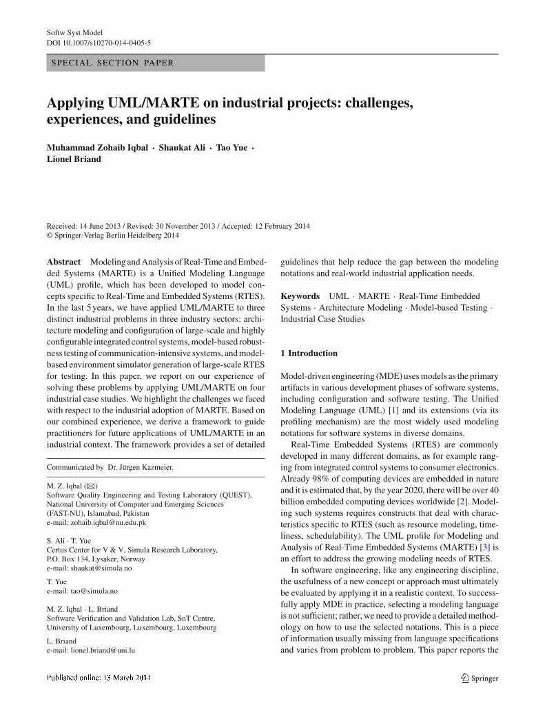
Fig. 6 Item component of the automated sorting machine
4.3.4 Example
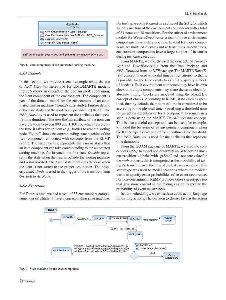
In this section, we provide a small example about the useof NFP_Duration stereotype for UML/MARTE models.Figure 6 shows an excerpt of the domain model containingthe Item component of the environment. The component ispart of the domain model for the environment of an auto-mated sorting machine (Tomra’s case study). Further detailsof the case study and the models are provided in [36,37]. TheNFP_Duration is used to represent the attributes that spec-ify time durations. The timeToNode attribute of the item canhave duration between 900 and 1,100 ms, which representsthe time it takes for an item (e.g., bottle) to reach a sortingnode. Figure 7 shows the corresponding state machine of theItem component annotated with concepts from the REMPprofile. The state machine represents the various states thatan item component can take corresponding to the automatedsorting machine, for instance, the first state Outside repre-sents the state when the item is outside the sorting machineand is not inserted. The Error state represents the case whenthe item is not sorted to the proper destination. The prop-erty timeToNode is used in the trigger of the transition fromOn_Belt to At_Node.
4.3.5 Key results
For Tomra’s case, we had a total of 55 environment compo-nents, out of which 43 have a corresponding state machine.
For testing, we only focused on a subset of the SUT, for whichwe only use four of the environment components with a totalof 23 states and 38 transitions. For the subset of environmentmodels for WesternGeco’s case, a total of three environmentcomponents have a state machine. In total for these compo-nents, we modeled 27 states and 46 transitions. In both cases,environment components have a large number of instancesduring test case execution.
From MARTE, we mostly used the concepts of TimedE-vent and TimedProcessing from the Time Package andNFP_Duration from the NFP package. The MARTE TimedE-vent concept is used to model timeout transitions, so that itis possible for the time events to explicitly specify a clock(if needed). Each environment component may have its ownclock or multiple components may share the same clock forabsolute timing. Clocks are modeled using the MARTE’sconcept of clocks. According to REMP, if no clock is spec-ified, then by default, the notion of time is considered to beaccording to the physical time. Specifying a threshold timefor an action execution or for a component to remain in astate is done using the MARTE TimedProcessing concept.This is also a useful concept and can be used, for example,to model the behavior of an environment component whenthe RTES expects a response from it within a time threshold.The NFP_Duration is used for the attributes that representtime durations.
From the GQAM package of MARTE, we used the con-cept of GaStep to model non-determinism. Whenever a time-out transition is labeled with “gaStep” and a nonzero value forthe prob property, this is interpreted as the probability of tak-ing the transition over the time of the test case execution. Thisstereotype was used to model scenarios where the modelerwants to specify exact probabilities of an event occurrence.For non-determinism, REMP provides other stereotypes toothat give more control to the testing engine to specify theprobability of event occurrences.
In our methodology, we chose Java as the action languagefor writing actions. The decision to choose Java as the action
Fig. 7 State machine for the Item component
123

Applying UML/MARTE on industrial projects
language at the model level is due to the lack of tool supportfor the UML action language (ALF) [43] at the time our toolwas developed. Testers of the SUT are also expected to bemore familiar with Java (consistent with our experience ofapplying the approach in two industrial contexts), rather thanwith a newly approved standard language. Moreover, ALFdoes not provide support for specifying time-related actions(e.g., corresponding to the MARTE’s concept of an RTActionto specify an atomic action). It was also not possible to specifytime delays with ALF. Both these concepts were used repeat-edly while modeling the environment of both industrial cases.
5 Challenges in industrial adoption of MARTE
In this section, we report the challenges that we realizedare hindering the successful industrial adoption of MARTE.First, we discuss practical problems that we faced, followedby the most common misconceptions surrounding MARTE.We observed these during discussions with our industrialpartners and working with them in the course of the projectsreported in the paper.
5.1 Practical problems in industrial adoption
This section highlights the practical problems that we facedin industrial applications of MARTE.
5.1.1 Lack of training material
In our observation, one of the major hurdles in industrialadoption of MARTE is the lack of proper training material.MARTE has been introduced in 2007, but during the courseof our projects, we did not find a lot of useful material fortraining, except the tutorials/presentation slides on the OMGwebsite and the MARTE specifications document itself. Withsuch a small amount of training material available, it is veryhard to convince the industrial partners about the sustain-ability of the proposed solutions based on MARTE. Industryneeds to rely on a firm body of knowledge that their engineerscan learn and work with. The specification document is notfor end users, but rather defines the semantics of MARTE.There is a real need for more training materials and books thatdescribe the various MARTE concepts and their applications.The recent book on MARTE [44] is a useful contribution inthis regard. In our cases, we studied the MARTE specifica-tion document and trained our industrial partners on how touse the selected subsets of MARTE.
5.1.2 Poor modeling tool support
There is a serious lack of proper tool support for UML/MARTE that is scalable for large industrial systems model-
ing. It is a common criticism on UML and MARTE that theyare too large and difficult to apply. In our experience, this isnot a problem with the standards (as we typically only use asmall subset of these standards, customized for specific pur-pose), rather this is a problem with tools. Software engineersare used to working in highly customizable and supportivedevelopment environments for programming. They expecta similar level of usability from the modeling tools, whichunfortunately is not the case.
According to the OMG’s website, there are only fivetools available that support MARTE. Among these, onlythree tools (i.e., Rational Software Architect 7.0, Magic-Draw 15.5, and Papyrus UML) support UML/MARTE mod-eling, and the two others focus on analysis based on MARTEmodels. Papyrus is freely available and Rational SoftwareArchitect and MagicDraw are both commercial products.When it comes to usability, in our experience with indus-try partners, none of these tools was “user-friendly.” UsingPapyrus required that a user be familiar with the underlyingmeta-model of UML/MARTE. We found that drawing statemachines and sequence diagrams was quite difficult. Ratio-nal Software Architect was deemed to be more user-friendlythan the other tools, but also had a number of drawbacks (asdiscussed further in Sect. 6.2.3). For example, the MARTEprofile is available only for version 7.0 and is not completelycompatible with the current version 8.5.
5.1.3 Lack of reported industrial evidence
Another obstacle in industrial adoption, making it difficultto convince industry partners, is a lack of reported indus-trial evidence of successful applications of MARTE. A well-known fact is that organizations are reluctant in applyingnew, untested technologies. It has been around a while sincethe introduction of MARTE but as mentioned in the relatedwork section, there are only a few reported applications ofMARTE. The lack of reported experience compounded withthe lack of training material makes it very hard to convinceindustry partners, as was the case in our context.
5.1.4 No defined methodology: Where to start from?
Another major challenge is that it is difficult for softwareengineers to identify where they should start when usingMARTE. It is a large standard, catering the typical needsof modeling and analysis of RTES, and as discussed ear-lier, in practice only a small part of MARTE is needed fora particular purpose. There is no reported methodology ofMARTE that guides the practitioners on how to use MARTEin particular contexts. Though we agree that it is not possibleto pre-define methodologies suitable for each particular con-text, we need generic methodologies and frameworks similarto the one reported in this paper.
123

M. Z. Iqbal et al.
5.1.5 Semantic gap and inconsistencies with UML
Another issue when using MARTE is that there are somesemantic inconsistencies with UML. These inconsistenciesin semantics can lead to hard to comprehend potentiallyambiguous or incorrect models. An effort should be made tomake the profile consistent with UML semantics. In its cur-rent form, if a profile is not defined so as to properly handlesuch inconsistencies, then these can cause serious problemsin the models.
For example, in the case of architecture modeling casestudy (Sect. 4.1), when “HwComponent” was used on a classin a class diagram to represent a hardware component, themeaning of its association with another class not carryingany stereotype becomes ambiguous. This is because UML istypically used to model software. Without having any stereo-type applied, a class by default implies that it is a softwareclass. Then, the association between a hardware componentclass and a software class should be given a specific meaning,like the deployment of the software to its hardware platform.In our cases, we address such semantic gaps in our modelingguidelines.
In our experience, there is limited action language supportfor MARTE concepts, such as time delays between actionsand the concept of RTAction (e.g., required to model atomicactions). This was primarily the case with environment-model-based testing case study, in which we aimed at gen-erating an executable simulator of the environment from themodels (Sect. 4.3). Even in the recently released Action Lan-guage for Foundational UML (ALF) [43], such concepts arenot supported. We used Java as an action language, whichprovided the concepts of real-time actions that we required.
5.1.6 Misconceptions surrounding UML/MARTE
Lastly, there are a number of misconceptions surroundingUML/MARTE that make it difficult to adopt UML/MARTEin industry. As stated earlier, we observed these misconcep-tions after discussions with our industrial partners. This paperis a step toward eliminating such misconceptions regardingUML/MARTE with the aim to make its adoption easier.
(a) MARTE is too big and complex to be used A commonperception regarding MARTE is that it is too big to be usedin practice. There is no denying the fact that it is a large pro-file as it is an international modeling standard addressing alarge number of requirements for modeling RTES. But aswe mentioned in this paper, the practitioners do not need touse or even understand the entire MARTE standard. Ratherthey should identify and use a small subset of MARTE thatis relevant to their problem (as was the case with our casestudies and the one reported in [20]). The industrial expe-rience reported by Henia et al. [23] is also an indicator of
this misconception. As discussed earlier (Sect. 3), their workextends UML/MARTE syntax to make it more “easy to use.”An example to show how complex a UML sequence dia-gram annotated with MARTE concepts is also presented. Webelieve that the readability problem highlighted is again ofthe tool support and not of MARTE (as discussed previouslyin Sect. 5.1.2). To increase the readability of the diagrams,the modeling tools should facilitate abstraction of details onthe diagrams.
(b) One needs to know entire UML to use MARTE SinceMARTE is a UML profile, another perception is that weneed to know the entire UML to use MARTE, making it aprohibitively large combination. In practice, only a relevantsubset of UML is required that is determined by the adoptedmodeling methodology. For all our case studies, where wedefined a subset of UML to be used with a subset of MARTE,e.g., UML state machines and class diagrams were used forthe environment-model-based testing of embedded systems(as discussed in Sect. 4.3).
(c) Creating customized DSLs is more beneficial than extend-ing MARTE By domain-specific languages (DSL), we referto the languages that are independent from existing lan-guages (such as UML) and are created from scratch, havingtheir own distinct meta-model and semantics. A commonperception among some industry practitioners is that, sinceUML/MARTE is large and complex, it is easier to developand use customized DSLs. Though we believe that DSLshave their own benefits, the reason mentioned above is notsufficient to develop a separate DSL. Using UML-based stan-dards also come with a number of benefits, including readilyavailable tool support and familiarity with the notation. Inaddition to modeling tools, analysis support is also availablefor MARTE models, for example with the Cheddar tool forscheduling analysis [45]. If the size of MARTE is an issue,one can simply use a subset suited for the selected purpose(as we did in our case studies). The problems related to toolusability are certainly not addressed by using a DSL, sincespecific tools have to be designed or tailored for a specificlanguage. Moreover, MARTE concepts are based on detailedsemantics (e.g., the semantics for clocks in the time package),and defining similar semantics for a DSL can be very com-plex and time-consuming.
(d) To apply MARTE, we need to learn other related lan-guages Modeling and Analysis of Real-Time and EmbeddedSystems comes with three other smaller languages: ValueSpecification Language (VSL), Clocked Value SpecificationLanguage (CVSL), and Clock Constraint Specification Lan-guage (CCSL). One may think that familiarity with all theselanguages is required to use MARTE. However, their use
123

Applying UML/MARTE on industrial projects
Fig. 8 Framework for guiding UML/MARTE applications
depends on the problem being solved. For example, we con-sidered using VSL for our projects, but we ended up optingfor OCL instead due to a lack of VSL support in RSA 8.5.
6 Framework for applying UML/MARTE in industry
In this section, we present a framework we devised by com-bining our experience in applying UML/MARTE on theindustrial problems described above. This framework aimsat supporting practitioners in their future applications ofUML/MARTE in industrial contexts. At a high level, theframework is presented as a UML activity diagram (Fig. 8)capturing what we believe are necessary steps for which wewill be providing guidance. Following, we briefly discusseach of these activities.
6.1 Perform domain analysis (A1)
Each of our industrial applications started from perform-ing a domain analysis. Domain analysis is defined as “theprocess by which information used in developing softwaresystems within the domain is identified, captured, and orga-nized with the purpose of making it reusable (to create assets)when building new products” [46]. Typically, domain analy-sis results in a domain model [47] that captures domain con-cepts and the relationships among them. A domain model canbe described using different notations, UML class diagramsbeing a frequently used one. For all the three applications, weused the UML class diagram notations and OCL for domainmodeling.
The objective of the domain analysis that we performedwas different from what is typically presented in object-oriented analysis and design methods [48]. More specifically,our domain analysis is not the start of the software analysisphase but its usage depends on the problem at hand. For archi-tectural modeling, the domain model was later used as a basisto derive the product line architecture modeling method-ology, including a UML profile and modeling guidelines.For both the model-based testing projects, domain analy-
sis resulted in the definition of either environment or sys-tem structure models (as class diagrams based on a profile),which were subsequently used, together with state machines,to facilitate automated test case generation.
To derive the domain models, we followed an iterativeprocess during which we had multiple sessions with ourindustry partners. In some cases, we initially used sketch-ing tools and simple drawings on white boards for ease ofunderstanding. We started by just capturing the concepts firstand later introduced associations and attributes in the domainmodels. Last, we also added OCL constraints on the domainmodel concepts. Detailed discussions on how the domainanalysis was performed in each of the applications are pro-vided in [49] for architectural modeling, in [35] for robust-ness testing, and in [42] for model-based testing of RTES.
For architectural modeling with FMC, the domain analy-sis took around 35 days. Further decomposition of the dura-tion and further details of various domain analysis activi-ties performed are described in detail in [49]. For model-based robustness testing with Cisco, the domain analysis tookapproximately around 15 days in total by two researchersand one test manager. For environment-model-based testingwith Tomra, the domain analysis involved two researchers,four half-day workshops with various members of the teamin live sessions and several one-to-one meetings with engi-neers. It took approximately 40 days in total to complete thedomain analysis. For WesternGeco, a partial domain modelwas already available, so it took approximately 30 days intotal to perform the domain analysis of the marine seismicacquisition system.
In all our cases, the domain analysis was useful in thefollowing ways: (i) It helped us in understanding and spec-ifying (as a domain model) the complexities of large-scalesystems involving multiple technical disciplines (e.g., elec-trical, mechanical, and software) and multiple stakeholders;(ii) It was instrumental in understanding the needs of ourindustry partners as it served as a communication mediumwith them; and (iii) It formed a basis for other activities thatwe carried out at later stages of the projects, such as definingthe modeling methodology and identifying the language and
123
M. Z. Iqbal et al.
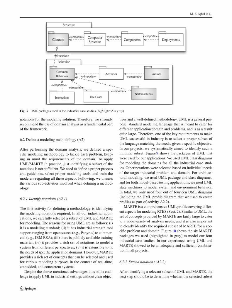
Fig. 9 UML packages used in the industrial case studies (highlighted in gray)
notations for the modeling solution. Therefore, we stronglyrecommend the use of domain analysis as a fundamental partof the framework.
6.2 Define a modeling methodology (A2)
After performing the domain analysis, we defined a spe-cific modeling methodology to tackle each problem, keep-ing in mind the requirements of the domain. To applyUML/MARTE in practice, just identifying a subset of thenotations is not sufficient. We need to define a proper processand guidelines, select proper modeling tools, and train themodelers regarding all these aspects. Following, we discussthe various sub-activities involved when defining a method-ology.
6.2.1 Identify notations (A2.1)
The first activity for defining a methodology is identifyingthe modeling notations required. In all our industrial appli-cations, we carefully selected a subset of UML and MARTEfor modeling. The reasons for using UML are as follows: (i)it is a modeling standard; (ii) it has industrial strength toolsupport ranging from open source (e.g., Papyrus) to commer-cial (e.g., IBM RSA); (iii) there is publicly available trainingmaterial; (iv) it provides a rich set of notations to model asystem from different perspectives; (v) it is extensible to fitthe needs of specific application domains. However, MARTEprovides a rich set of concepts that can be selected and usedfor various modeling purposes in the context of real-time,embedded, and concurrent systems.
Despite the above-mentioned advantages, it is still a chal-lenge to apply UML in industrial settings without clear objec-
tives and a well-defined methodology. UML is a general pur-pose, standard modeling language that is meant to cater fordifferent application domain and problems, and is as a resultquite large. Therefore, one of the key requirements to makeUML successful in industry is to select a proper subset ofthe language matching the needs, given a specific objective.In our projects, we systematically aimed to identify such aminimal subset. Figure 9 shows the packages of UML thatwere used for our applications. We used UML class diagramsfor modeling the domains for all the industrial case stud-ies. Other notations were selected based on individual needsof the target industrial problem and domain. For architec-tural modeling, we used UML package and class diagrams,and for both model-based testing applications, we used UMLstate machines to model system and environment behavior.In total, we only used four out of fourteen UML diagrams(including the UML profile diagram that we used to createprofiles as part of activity A2.2).
MARTE is a comprehensive UML profile covering differ-ent aspects for modeling RTES (Sect. 2). Similar to UML, theset of concepts provided by MARTE are fairly large to caterto a wide variety of analysis needs, and it is also importantto clearly identify the required subset of MARTE for a spe-cific problem and domain. Figure 10 shows the six MARTEpackages we used (highlighted in gray) to model our fourindustrial case studies. In our experience, using UML andMARTE showed to be an adequate and sufficient combina-tion in all projects.
6.2.2 Extend notations (A2.2)
After identifying a relevant subset of UML and MARTE, thenext step should be to determine whether the selected subset
123

Applying UML/MARTE on industrial projects
Fig. 10 MARTE packages used in the industrial case studies (high-lighted in gray)
of available notations is sufficient to address our problems.Various steps that we performed in this activity are summa-rized as an activity diagram in Fig. 11. First, we evaluatedwhether the identified MARTE subset was sufficient. If thiswas not the case, we tried to extend MARTE using the definedconstructs (e.g., by adding a new NFP). When required, wefurther defined guidelines on how to extend MARTE (forexample, see [35]) in the future. We then evaluated whetherthe identified subsets of UML, MARTE, and its extensionswere sufficient for our modeling purposes. If this was not thecase, we extended UML by creating UML profiles. In [50],two main approaches for profile creation are discussed. Thefirst approach directly implements a profile by defining keyconcepts of a target domain, such as what was done to defineSysML [51]. The second approach first creates a conceptualmodel outlining the key concepts of a target domain followedby creating a profile for the identified concepts, such as whatwas done to define SPT [9] and MARTE. We used the secondapproach to define profiles since it is more systematic as itclearly separates the profile creation process into two distinctstages.
We found the MARTE NFP package and the exten-sion mechanism sufficient for our industrial applicationof model-based robustness testing. The NFP package pro-vides different data types such as NFP_Percentage andNFP_DataTxRate, which are helpful to model properties ofthe environment, for instance jitter and packet loss in net-works. When the built-in data types of MARTE are not suffi-
cient, the open modeling framework of MARTE can be usedto define new NFP types by either extending the existingNFPs or by defining completely new NFPs. For example, weextended MARTE’s NFPs and defined several properties ofthe environment when modeling echo in audio streams andsynchronization mismatch between audio and video streamscoming to a video conferencing system. We can safely con-clude that the MARTE profile and its open modeling frame-work were sufficient to model relevant properties of the Sat-urn operating environment (Sect. 4.2). However, to addressrobustness testing, we defined a UML profile called Robust-Profile [35] to model faults and their properties. The profilesupports the modeling of recovery mechanisms when a faulthas occurred and the modeling of states that a system cantransition to when it has recovered. Since these features werenot part of MARTE, a profile was required.
For architecture modeling, we proposed the use of sixnew concepts as stereotypes to extend UML. For model-based robustness testing, we proposed 30 new stereotypesto extend UML and MARTE, and for environment-model-based testing profile, we proposed eight new stereotypes toextend UML concepts. Overall, we can see that a limitednumber of stereotypes were required to extend UML for allthe three projects. For robustness testing, most of the newstereotypes were based on a fault model and were extendingMARTE NFPs.
6.2.3 Tool selection (A2.3)
An important consideration for the practical adoption of amodeling methodology in industrial settings is the selectionof an adequate modeling tool. This is important since modelsare usually meant to support the automation of some impor-tant task (e.g., software test automation). The modeling toolshould therefore provide support to export the models in astandard format, which can later be processed by other MDEtools (e.g., for model transformations and OCL parsers).According to the MARTE official website [52], the MARTEprofile is available in four tools: IBM RSA [33], IBM Rhap-sody [53], Papyrus UML [54], and MagicDraw [55].
Among these modeling tools, only IBM RSA and PapyrusUML are EMF-based and hence can be used with other EMF-
Fig. 11 Sub-activities under the activity A2.2 extend notations
123

M. Z. Iqbal et al.
based MDE tools (e.g., Kermeta for model transformations).For Papyrus UML, we faced serious usability problems whenmodeling state machines, since most of the interface of thetool is based on the assumption that the modeler is aware ofthe underlying UML metamodel. IBM RSA comes with ahigh price tag to be used in small-to-medium-sized compa-nies. Even IBM RSA has usability issues, for instance, it isnot possible to directly link a modeling element in the actionlanguage. One common scenario is when the engineer wantsto send a signal to an object in the action code (e.g., as partof the effect of a trigger). In this case, there is no tool levellink of the action code with the target object or the signal.The engineer has to manually verify whether she is using thesame name of the signal, which was defined in the model.The scenario gets worse, when one has to change the name ofa signal or remove a signal. The only option is to traverse allthe action code in the model and manually modify or removethe line sending the signal. This was a serious setback interms of usability of the tool. Similarly, the MARTE profileis only compatible with RSA version 7.0 and, if used withlater versions, does not support the Value Specification Lan-guage (VSL) editor. Due to this reason and that a completeparser of VSL was not available at the time we worked onthe cited industrial projects, we used OCL to specify valuesfor NFPs and other MARTE types.
For one of the projects, we also worked with EnterpriseArchitect [56]. Though Enterprise Architect is affordablefor smaller companies, migrating its models to a form com-patible to Eclipse Modeling Framework (EMF)-based toolsis not trivial. EMF is a widely accepted format for inter-changing UML models and is supported by a number ofmodeling tools, including Rational Software Architect andPapyrus. A number of model-manipulating tools and tech-nologies are built on EMF, including a number of modeltransformation languages (such as Kermeta [57] and MOF-Script [58]). In all our cases, model manipulation was doneusing the EMF-based tools, and therefore, it was very impor-tant for the modeling tool to be compatible with EMF. Enter-prise Architect uses a database to store the model instances.The definition of the underlying concepts does not conformto EMF; therefore, the generated XMI[UML] files are notcompatible with EMF-based tools. Initially for the domainmodel, we also used a sketching tool (Omnigraffle [59])for one of the cases, which was easier to use for industrypartners because it did not enforce any constraint on themodeling.
Overall, we found IBM RSA as the most viable modelingtool in terms of usability and its interoperability with thirdparty MDE tools. In addition, it is a commercial tool, imply-ing a better maintenance and training support compared withopen source modeling tools.
6.2.4 Define guidelines (A2.4)
The next step is to define guidelines on how to model withthe selected notations. As discussed earlier, only specify-ing a set of notations is not sufficient and we need a propermethodology to help modelers determine what to model,in which order, using which specific notation, and at whatlevel of detail. We followed this step in all our case stud-ies and defined guidelines that are not generic and are, tosome extent, specific to each application domain and tar-geted problem. For example, for the environment-model-based testing project (Sect. 4.3), we defined guidelines tohelp modelers identify test-relevant environment conceptsand their relationships in the context of embedded systems[42]. According to our experience, such guidelines are crucialfor modelers to correctly and effectively apply our modelingnotations.
6.3 Application of methodology
Once the methodology was defined, the next step is to applythe methodology. For this purpose, we suggest a numberof training sessions, workshops, and close mentoring of theengineers in the use of the methodology, selected tool, andthe notations.
In all our cases, a number of training sessions took place,which ranged from acquiring basic UML modeling skills tomore advanced, methodology-specific training. Training wasconducted in an interactive manner, where the attendees weregiven exercises based on their own domain and systems. Thislast point is very important as people more easily understandand adopt technologies that have shown to apply to theirenvironment.
Training must be complemented by workshops where themethodology providers (e.g., researchers) model the solutionto a representative (sub-)problem with trainees, thus reducingthe initial learning curve with respect to the modeling tooland notations. Later, when the first modeling activities areundertaken, mentoring is also required, at least in the initialstages, until a certain level of comfort is attained. A naturaltendency is for people to revert to previous practices whenfaced with a seemingly intractable problem.
Referring back to our example projects, modeling thearchitecture for FMC took around 120 days involving oneresearcher and one PhD student. Modeling the Saturn prod-uct line consumed approximately 60 days involving oneresearcher and one test engineer from Cisco. Environmentmodeling with Tomra required around 2 months with onePhD student and one researcher. The initial modeling of theenvironment at WesternGeco took approximately 60 days forone PhD student and one researcher.
123

Applying UML/MARTE on industrial projects
6.4 Summary and discussions
In our three industrial projects, we used the UML class, pack-age, and state machine diagrams for modeling the differentaspects of software systems. From MARTE, we used con-cepts from the MARTE Time, NFP, GQAM, Alloc, GRM,and HRM packages. Over the years, a number of researchersand industry practitioners have raised the concern that UMLis too large [60,61]. Recently, the same has been writtenabout MARTE [18]. In our opinion and based on our prac-tice, UML and MARTE are meant to provide an encom-passing set of modeling notations catering diverse needs. Tosuccessfully apply these standards to industrial projects, weneed a complete methodology that identifies the subset ofUML and MARTE to be used to address specific problemsin specific contexts and guidelines to help people apply suchstandards in a systematic and consistent manner.
A complete methodology based on UML/MARTE shouldbe derived for a specific purpose, to address a particular prob-lem in a particular domain. To do so, we found that a thor-ough domain analysis is an important step, which, as wediscussed in Sect. 6.1, is a necessary basis not just for systemanalysis but also to make decisions during notations selec-tion and methodology definition activities. Depending on thecomplexity of the domain under analysis and the nature ofthe problem, domain analysis activities and the effort theyrequire vary significantly from case to case. The next stepsare to carefully select a minimal subset of UML and MARTEnotations and if needed, extend MARTE, for example bydefining new NFPs, and extend UML by defining a profile.Though the selection of a modeling tool might seem to be atrivial process, in our experience, this can have large impacton adoption by industry partners. If needed, the modelingtool should be customized based on the modeling notationsselected, so that concepts of UML and MARTE that are notrelevant are also not visible to the end user. Along with thenotations, we found it an essential step to provide a set ofmodeling guidelines for the end user, which will help her toproperly use these notations.
For model-based robustness testing of RTES, we defineda profile for modeling faults and their properties, recoverymechanisms, and faulty states. These are based on well-defined fault models in the literature and are applicable toRTES in general. These concepts can be a good addition asthey align with the goals of the MARTE profile, though thisrequires further investigation.
7 Conclusion
Applying model-driven Engineering (MDE) notations andmethodologies to real-life industrial problems is a challeng-ing task and very few articles in the research literature report
on such experiences. For successful MDE application, a com-prehensive modeling methodology should be adapted that isspecific to the problem being solved and adequate for theapplication domain. This paper discusses our experiences ofapplying the UML profile for Modeling and Analysis of Real-Time Embedded Systems (MARTE) to solve three distinctindustrial problems related to the use of real-time embeddedsystems (RTES) in four different industry sectors. The indus-trial problems that we tackled were related to architecturalmodeling and configuration, model-based robustness testing,and environment-model-based testing of RTES. We listed anumber of common challenges in the industrial adoption ofUML/MARTE. To address these challenges and based on ourexperiences, we derived a framework to guide practitionersin their application of UML/MARTE in industrial contexts.This is expected to help practitioners bridge the gap betweenthe UML/MARTE standard and the modeling needs of indus-trial RTES development.
Acknowledgments We are thankful to our industry partners fromFMC Technologies, Cisco Systems, Tomra, and Westerngeco, all fromNorway for their technical support. Muhammad Zohaib Iqbal was partlysupported by ICT R&D Fund, Pakistan (ICTRDF/MBTToolset/2013)and by National Research Fund, Luxembourg (FNR/P10/03). LionelBriand was supported by the National Research Fund, Luxembourg(FNR/P10/03).
References
1. OMG: Unified Modeling Language Superstructure, Version 2.4.1.http://www.omg.org/spec/UML/2.4.1 (2011)
2. Artemis: Artemis Joint Undertaking—The Public Private Part-nership for R & D Embedded Systems. http://artemis-ju.eu/embedded_systems (2013)
3. OMG: Modeling and Analysis of Real-time and Embedded sys-tems (MARTE), Version 1.1. http://www.omg.org/spec/MARTE/1.1/ (2011)
4. FMC Technologies. http://www.fmctechnologies.com5. Cisco Inc. http://www.cisco.com6. WesternGeco. http://www.slb.com/services/westerngeco.aspx7. Tomra AS. http://www.tomra.no8. Iqbal, M., Ali, S., Yue, T., Briand, L.: Experiences of applying
UML/MARTE on three industrial projects. In: Model Driven Engi-neering Languages and Systems. vol. 7590, pp. 642–658. Springer,Berlin (2012)
9. OMG: UML Profile for Schedulability, Performance and Time.http://www.omg.org/technology/documents/profile_catalog.htm(2010)
10. Pohl, K., Bockle, G., Van Der Linden, F.: Software Product LineEngineering: Foundations, Principles, and Techniques. Springer,New York (2005)
11. Van Der Linden, F., Schmid, K., Rommes, E.: Software ProductLines in Action: The Best Industrial Practice in Product Line Engi-neering. Springer, New York (2007)
12. IEEE Standard Glossary of Software Engineering Terminology.IEEE, IEEE Std 610.12-19901990
13. IEEE Standard Dictionary of Measures of the Software Aspects ofDependability. IEEE Std 982.1-2005 (Revision of IEEE Std 982.1-1988), pp. 1–34 (2006)
123

M. Z. Iqbal et al.
14. Standard for Software Quality Characteristics. International Orga-nization for Standardization, ISO-9126-32003
15. Software Assurance Standard. NASA Technical Standard, NASA-STD-8739.82005
16. Demathieu, S., Thomas, A.F., Andre, A.C., Gerard, S., Terrier, F.:First experiments using the UML profile for MARTE. In: 11th IEEESymposium on Object Oriented Real-Time, Distributed Comput-ing, pp. 50–57 (2008)
17. Briand, L., Falessi, D., Nejati, S., Sabetzadeh, M., Yue, T.:Research-based innovation: a tale of three projects in model-drivenengineering. In: Model Driven Engineering Languages and Sys-tems. vol. 7590, pp. 793–809. Springer, New York (2012)
18. Espinoza, H., Richter, K., Gérard, S.: Evaluating MARTE in anindustry-driven environment: TIMMO’s challenges for AUTOSARtiming modeling. In: Design Automation and Test in Europe(DATE) (2008)
19. Heinecke, H., Bielefeld, J., Schnelle, K.-P., Maldener, N., Fennel,H., Weis, O., Weber, T., Ruh, J., Lundh, L., Sandén, T.: AUTOSAR-current results and preparations for exploitation. In: EuroforumConference (2006)
20. Middleton, S.E., Servin, A., Zlatev, Z., Nasser, B., Papay, J.,Boniface, M.: Experiences using the UML profile for MARTE tostochastically model post-production interactive applications. In:eChallenges 2010, pp. 1–8 (2010)
21. Quadri, I.R., Gamatié, A., Boulet, P., Meftali, S., Dekeyser, J.-L.:Expressing embedded systems configurations at high abstractionlevels with UML MARTE profile: advantages, limitations and alter-natives. J. Syst. Archit. 58, 178–194 (2012)
22. Belategi, L., Sagardui, G., Etxeberria, L., Azanza, M.: Embeddedsoftware product lines: domain and application engineering model-based analysis processes. processes. J. Softw. Evol. Proc. (2012).doi:10.1002/smr.1568
23. Henia, R., Rioux, L., Vergnaud, T.: Industrial adaptation ofMARTE for early scheduling analysis of component-based appli-cations. In: 4ht International Workshop on Nonfunctional Sys-tem Properties in Domain Specific Modeling Languages, p. 7(2012)
24. Koudri, A., Cuccuru, A., Gerard, S., Terrier, F.: Designing het-erogeneous component based systems: evaluation of MARTEstandard and enhancement proposal. In: Model Driven Engi-neering Languages and Systems: pp. 243–257. Springer, Berlin(2011)
25. Vidal, J., De Lamotte, F., Gogniat, G., Soulard, P., Diguet, J.-P.:A co-design approach for embedded system modeling and codegeneration with UML and MARTE. In: Design, Automation andTest in Europe Conference and Exhibition, 2009. DATE’09, pp.226–231 (2009)
26. Choi, J., Bae, D.-H.: An Approach to Constructing Timing Dia-grams from UML/MARTE Behavioral Models for Guidance andControl Unit Software. In: Computer Applications for Database,Education, and Ubiquitous Computing: pp. 107–110. Springer,New York (2012)
27. Peñil, P., Medina, J., Posadas, H., Villar, E.: Generating heteroge-neous executable specifications in SystemC from UML/MARTEmodels. Innov. Syst. Softw. Eng. 6, 65–71 (2010)
28. Medina, J.L., Cuesta, A.G.: Model-based analysis and design ofreal-time distributed systems with Ada and the UML profile forMARTE. In: Reliable Software Technologies-Ada-Europe, pp. 89–102. Springer, New York 2011 (2011)
29. Mraidha, C., Tucci-Piergiovanni, S., Gerard, S.: Optimum: aMARTE-based methodology for schedulability analysis at earlydesign stages. ACM SIGSOFT Softw. Eng. Notes 36, 1–8(2011)
30. Sun, Q., Huang, X., Li, J., Zhang, T.: Timing Aspects Construc-tion Using UML-MARTE Profile. In: Trustworthy Computing andServices: pp. 474–481. Springer, New Yok (2013)
31. Merseguer, J., Bernardi, S.: Dependability analysis of DES basedon MARTE and UML state machines models. Discret. Event Dyn.Syst. 22, 163–178 (2012)
32. Behjati, R., Yue, T., Briand, L.C., Selic, B.: SimPL: a product-linemodeling methodology for families of integrated control systems.Inf. Softw. Technol. 55(3), 607–629 (2013)
33. IBM Rational Software Architect. http://www.ibm.com/developerworks/rational/products/rsa/
34. Cisco Telepresence Integrator C Series. http://www.cisco.com/en/US/products/ps11422/index.html
35. Ali, S., Briand, L.C., Hemmati, H.: Modeling robustness behaviorusing aspect-oriented modeling to support robustness testing ofindustrial systems. Softw. Syst. Model. 11, 633–670 (2012)
36. Iqbal, M.Z., Arcuri, A., Briand, L.: Code generation fromUML/MARTE/OCL Environment Models to Support AutomatedSystem Testing of Real-time Embedded Software. Simula ResearchLaboratory, Technical, Report (2011–04) (2011)
37. Iqbal, M.Z., Arcuri, A., Briand, L.: Environment modeling and sim-ulation for automated testing of soft real-time embedded software.Softw. Syst. Model. (2013). doi:10.1007/s10270-013-0328-6
38. Arcuri, A., Iqbal, M., Briand, L., et al.: Black-box system testingof real-time embedded systems using random and search-basedtesting. In: Petrenko, A. (ed.) Testing Software and Systems, vol.6435, pp. 95–110. Springer, Berlin (2010)
39. Iqbal, M.Z., Arcuri, A., Briand, L.: Empirical investigation ofsearch algorithms for environment model-based testing of real-time embedded software. In: International Symposium on SoftwareTesting and Analysis (ISSTA), pp. 199–209 (2012)
40. Iqbal, M.Z., Arcuri, A., Briand, L.: Automated System Testingof Real-Time Embedded Systems Based on Environment Mod-els. Simula Research Laboratory, Technical, Report (2011–19)(2011)
41. Iqbal, M.Z., Arcuri, A., Briand, L.: Combining search-based andadaptive random testing strategies for environment model-basedtesting of real-time embedded systems. In: Symposium on Search-based, Software Engineering, pp. 136–151 (2012)
42. Iqbal, M.Z., Arcuri, A., Briand, L.: Environment modeling withUML/MARTE to support black-box system testing for real-timeembedded systems: methodology and industrial case studies. In:Petriu, D. (ed.) Model Driven Engineering Languages and Systems,vol. 6394, pp. 286–300. Springer, Berlin (2010)
43. OMG: Concrete Syntax for UML Action Language (Action Lan-guage for Foundational UML - ALF), Version 1.0.1. http://www.omg.org/spec/ALF/1.0.1 (2013)
44. Selic, B., Gérard, S.: Modeling and Analysis of Real-Time andEmbedded Systems with UML and MARTE: Developing Cyber-Physical Systems. Morgan Kaufmann, Burlington (2013)
45. Cheddar. http://beru.univ-brest.fr/~singhoff/cheddar/ (2011)46. America, P., Thiel, S., Ferber, S., Mergel, M.: Introduction to
Domain Analysis, Eureka 2023 Programme (2001)47. Conceptual Model (computer science): http://en.wikipedia.org/
wiki/Conceptual_model_(computer_science)48. Larman, C.: Applying UML and Patterns: An Introduction to
Object-Oriented Analysis and Design and the Unified Process.Prentice Hall PTR, Upper Saddle River, NJ (2001)
49. Yue, T., Briand, L., Selic, B., Gan, Q.: Experiences with Model-based Product Line Engineering for Developing a Family of Inte-grated Control Systems: an Industrial Case Study. Simula ResearchLaboratory, Technical Report (2012–06) (2012)
50. Lagarde, F., Espinoza, H., Terrier, F., André, C., Gérard, S.: Lever-aging patterns on domain models to improve UML profile def-inition. In: Fundamental Approaches to Software Engineering(2008)
51. Weilkiens, T.: Systems Engineering with SysML/UML: Modeling,Analysis, Design. Morgan Kaufmann, Burlington (2008)
123

Applying UML/MARTE on industrial projects
52. MARTE Tools. http://www.omgmarte.org/node/3153. IBM (2011) IBM Rational Rhapsody. http://www.ibm.com/
software/awdtools/rhapsody/54. Papyrus UML. http://www.papyrusuml.org55. MagicDraw. http://www.magicdraw.com/56. Enterprise Architect. http://www.sparxsystems.com/57. Kermeta. http://www.kermeta.org/58. Oldevik, J.: MOFScript user guide. Version 0.6 (MOFScript v 1.1.
11) (2006)59. OmniGraffle. http://www.omnigroup.com/products/omnigraffle/60. Grossman, M., Aronson, J.E., McCarthy, R.V.: Does UML make
the grade? Insights from the software development community. Inf.Softw. Technol. 47, 383–397 (2005)
61. Suess, J.G., Fritzson, P., Pop, A.: The impreciseness of UML andimplications for modelicaML. In: Workshop on Equation-BasedObject-Oriented Languages and Tools, (EOOLT’2008), pp. 17–26(2008)
Muhammad Zohaib Iqbal iscurrently an Assistant Profes-sor at the Department of Com-puter Science, National Univer-sity of Computer and Emerg-ing Sciences (Fast-NU), Islam-abad, Pakistan and a research fel-low at the Software Verificationand Validation Lab, Interdiscipli-nary Centre for Security, Relia-bility and Trust (SnT), Univer-sity of Luxembourg. At FAST-NU, he is the lead scientist atthe Software Quality Engineer-ing and Testing (QUEST) Lab-oratory. He received his Ph.D.
degree in software engineering from University of Oslo, Norway in2012. Before joining Fast-NU, he was a research fellow at SimulaResearch Laboratory, Norway. He has also worked as a Lecturer atthe Department of Computer Science, International Islamic University,Islamabad, Pakistan, and Department of Computer Science, Moham-mad Ali Jinnah University, Pakistan. His research interests includemodel-driven engineering, software testing, and empirical softwareengineering. He has been involved in research projects in these areassince 2004.
Shaukat Ali is currently aresearch scientist in Certus Soft-ware Verification and ValidationCenter, Simula Research Labora-tory, Norway. He has been affil-iated to Simula Research Labsince 2007. He has been involvedin many industrial and researchprojects related to Model-basedTesting (MBT) and Empiri-cal Software Engineering since2003. He has experience of work-ing in several industries and aca-demic research groups in manycountries including UK, Canada,Norway, and Pakistan.
Tao Yue received her BEngdegree in the Department ofAutomation Science and Electri-cal Engineering, Beihang Uni-versity, China, the M.A.Sc andPh.D. degrees in the Depart-ment of Systems and ComputerEngineering at Carleton Univer-sity, Ottawa, Canada in 2006and 2010, respectively. She isnow a senior research scientistof Simula Research Laboratory,Oslo, Norway, where she is lead-ing the expertise area of model-driven engineering (MDE). Shehas around 16 years of experi-
ence of conducting industry-oriented research with a focus on MDEin various application domains such as Avionics, Maritime and Energy,and Communications in several countries including Canada, Norway,and China. Her main research area is software engineering, with spe-cific interested in requirements engineering, model-based development,model-based configuration and variability modeling, and empirical soft-ware engineering.
Lionel Briand is professor andFNR PEARL chair in softwareverification and validation at theSnT centre for Security, Relia-bility, and Trust, University ofLuxembourg. Lionel started hiscareer as a software engineerin France (CS Communicationsand Systems) and has conductedapplied research in collaborationwith industry for more than 20years. Until moving to Luxem-bourg in January 2012, he washeading the Certus center forsoftware verification and valida-tion at Simula Research Labora-
tory, where he was leading applied research projects in collaborationwith industrial partners. Before that, he was on the faculty of thedepartment of Systems and Computer Engineering, Carleton Univer-sity, Ottawa, Canada, where he was full professor and held the CanadaResearch Chair (Tier I) in Software Quality Engineering. He has alsobeen the software quality engineering department head at the Fraun-hofer Institute for Experimental Software Engineering, Germany, andworked as a research scientist for the Software Engineering Laboratory,a consortium of the NASA Goddard Space Flight Center, CSC, and theUniversity of Maryland, USA. Lionel has been on the program, steer-ing, or organization committees of many international, IEEE and ACMconferences. He is the coeditor-in-chief of Empirical Software Engi-neering (Springer) and is a member of the editorial boards of Systemsand Software Modeling (Springer) and Software Testing, Verification,and Reliability (Wiley). He was on the board of IEEE Transactions onSoftware Engineering from 2000 to 2004. Lionel was elevated to thegrade of IEEE Fellow for his work on the testing of object-oriented sys-tems. He was recently granted the IEEE Computer Society Harlan Millsaward for his work on model-based verification and testing. His researchinterests include: software testing and verification, model-driven soft-ware development, search-based software engineering, and empiricalsoftware engineering.
123