applied thermodynamics - engr. adnan qamarengineersedge.weebly.com/uploads/4/6/8/0/4680709/... ·...
TRANSCRIPT
Applied Thermodynamics
Experiment_01_MT_234
Instructor: Mr. Adnan Qamar
Mechanical Engineering Department
1

Experiment No. 01: To test that Pressure is an intensive property.
Apparatus: Nozzle Distribution Unit
2

3

PROCESS DIAGRAM AND ELEMENTS ALLOCATION
4
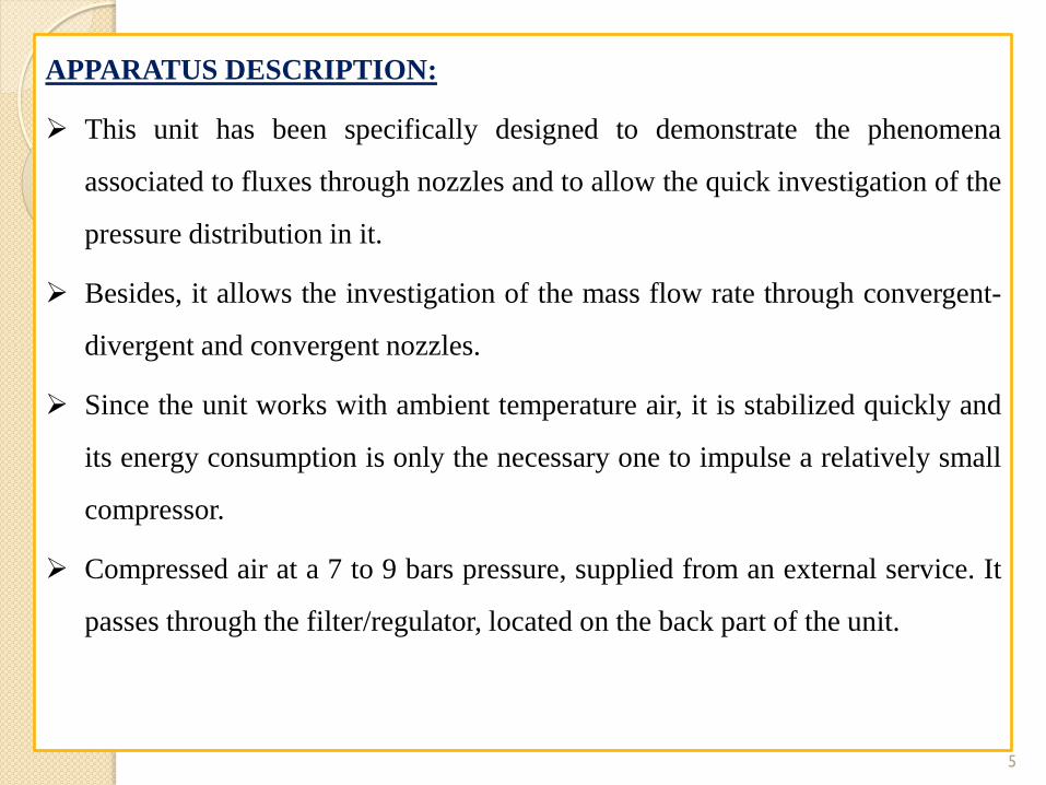
APPARATUS DESCRIPTION:
This unit has been specifically designed to demonstrate the phenomena
associated to fluxes through nozzles and to allow the quick investigation of the
pressure distribution in it.
Besides, it allows the investigation of the mass flow rate through convergent-
divergent and convergent nozzles.
Since the unit works with ambient temperature air, it is stabilized quickly and
its energy consumption is only the necessary one to impulse a relatively small
compressor.
Compressed air at a 7 to 9 bars pressure, supplied from an external service. It
passes through the filter/regulator, located on the back part of the unit.
5

APPARATUS DESCRIPTION:
In the unit, the air passes through a control valve, which allows an accurate
control of the pressure at the inlet of the nozzle.
The pressure and inlet temperature are measured and then the air is expanded
through the nozzle chosen.
When discharging from the nozzle, the pressure is controlled by other valve,
and the air goes finally through a flow meter to the atmosphere.
The nozzles have been made of brass, have been mechanised accurately and
several pressure tappings are available, being each one connected to its own
manometer to indicate the static pressure.
6

APPARATUS SPECIFICATIONS:
Bench-top unit. Anodized aluminium structure and panels in painted steel.
Diagram in the front panel with similar distribution to the elements in the real
unit.
Nozzles: Convergent type (conical), with 6 pressure tappings. Convergent-
divergent type, with 5 pressure tappings, for a design pressure ratio of 0.25.
Convergent- divergent, with 8 pressure tappings, for a design pressure ratio of
0.1. Nozzles can be changed quickly and easily.
2 Pressure meters (manometers), 100 mm. diameter, to measure air inlet and
outlet pressures (range: 0 to 10 bar). 8 Pressure meters (manometers), 60 mm.
diameter, to determine the pressure at the nozzle tappings (range: -1 to 8 bar).
7

8
APPARATUS SPECIFICATIONS:
Variable area type flow meter to indicate air flow at standard conditions (p=
1.2kg/m3). (Correction factors for other pressures and temperatures are
provided). Range 0 to 9 g/s. 2 Glass temperature meters, to indicate air
temperature before and after nozzle(range: 0 to 50ºC).Valves to give a fine
control of air inlet pressure and outlet pressure.
Air filter and pressure regulator to provide constant pressure, clean and water
free air to the unit. This is to be installed by the customer in the pipe between
his compressed air service and the unit, and must be drained regularly.
Works a ambient temperature- stabilises immediately. Allows students to make
a comprehensive investigation in a normal laboratory period. Gives students
an opportunity to calibrate equipment. Cables and accessories, for normal
operation.

PRESSURE:
Pressure is defined as a normal force exerted by a fluid per unit area. We speak of
pressure only when we deal with a gas or a liquid. The counterpart of pressure in
solids is normal stress. Since pressure is defined as force per unit area, it has the unit
of newton per square meter (N/m2), which is called a Pascal (Pa). That is,
1 Pa =1 N/m2
The pressure unit Pascal is too small for pressures encountered in practice. Therefore,
its multiples kilopascal (1 kPa = 103 Pa) and mega Pascal (1 MPa = 106 Pa) are
commonly used. Three other pressure units commonly used in practice, especially in
Europe, are bar, standard atmosphere, and kilogram-force per square centimeter:
1 bar= 105 pa=0.1 MPa=100kPa : 1 atm= 101,325 pa=101.325kPa=1.01325bars
1kgf/cm3 =9.807N/cm3 =9.807 ×10⁴N/m2=9.807 × 104Pa=0.9807bar=0.9679atm
9

Absolute pressure: The actual pressure at a given position. It is measured
relative to absolute vacuum (i.e., absolute zero pressure).
Gage pressure: The difference between the absolute pressure and the local
atmospheric pressure. Most pressure-measuring devices are calibrated to read
zero in the atmosphere, and so they indicate gage pressure.
Vacuum pressures: Pressures below atmospheric pressure.
10

11

Variation of Pressure with Depth:
Pressure in a fluid at rest does not change in the horizontal direction. This can
be shown easily by considering a thin horizontal layer of fluid and doing a
force balance in any horizontal direction. However, this is not the case in the
vertical direction in a gravity field.
Pressure in a fluid increases with depth because more fluid rests on deeper
layers, and the effect of this “extra weight” on a deeper layer is balanced by an
increase in pressure.
12

When the variation of density with
elevation is known
The pressure of a fluid at rest increases
with depth (as a result of added weight).
The pressure of a fluid at rest increases
with depth (as a result of added weight).
ghP
ghPP
zzgPPP
gage
atm
s
12
2
1
12 zgPPP
13
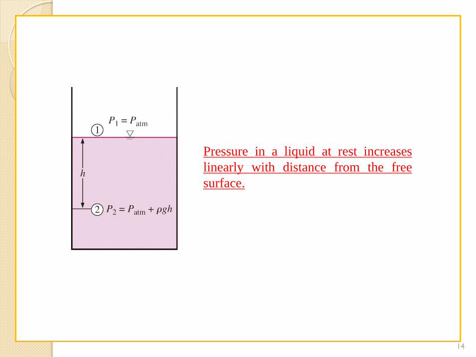
Pressure in a liquid at rest increases
linearly with distance from the free
surface.
14
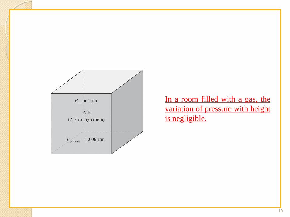
In a room filled with a gas, the
variation of pressure with height
is negligible.
15

The pressure is the same at all points on a horizontal plane in
a given fluid regardless of geometry, provided that the points
are interconnected by the same fluid.
16
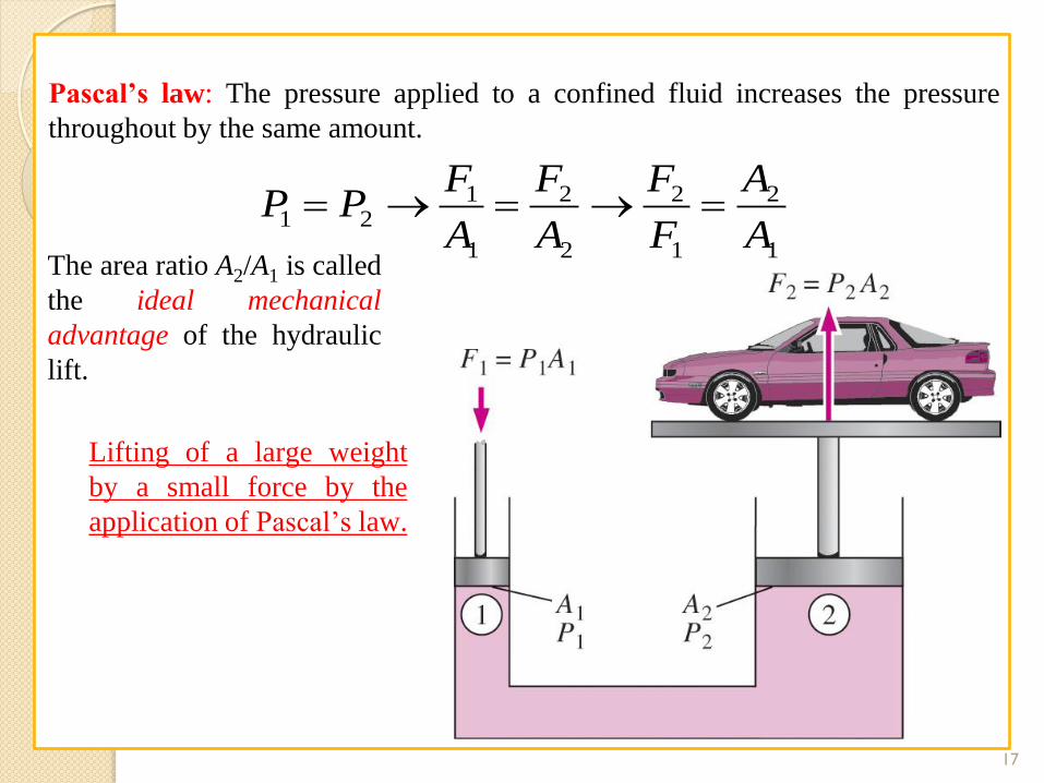
Pascal’s law: The pressure applied to a confined fluid increases the pressure
throughout by the same amount.
1
2
1
2
2
2
1
121
A
A
F
F
A
F
A
FPP
The area ratio A2/A1 is called
the ideal mechanical
advantage of the hydraulic
lift.
Lifting of a large weight
by a small force by the
application of Pascal’s law.
17
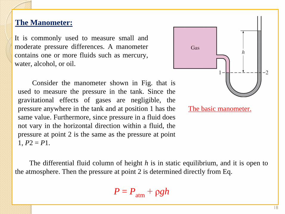
The Manometer:
It is commonly used to measure small and
moderate pressure differences. A manometer
contains one or more fluids such as mercury,
water, alcohol, or oil.
The basic manometer.
Consider the manometer shown in Fig. that is
used to measure the pressure in the tank. Since the
gravitational effects of gases are negligible, the
pressure anywhere in the tank and at position 1 has the
same value. Furthermore, since pressure in a fluid does
not vary in the horizontal direction within a fluid, the
pressure at point 2 is the same as the pressure at point
1, P2 = P1.
The differential fluid column of height h is in static equilibrium, and it is open to
the atmosphere. Then the pressure at point 2 is determined directly from Eq.
P = Patm + ρgh
18

In stacked-up fluid layers, the pressure change across
a fluid layer of density and height h is gh.
Measuring the pressure drop across a flow
section or a flow device by a differential
manometer.
ghPP
PgaghhagP
)(21
)(
12
21211
1332211 PghghghPatm
19
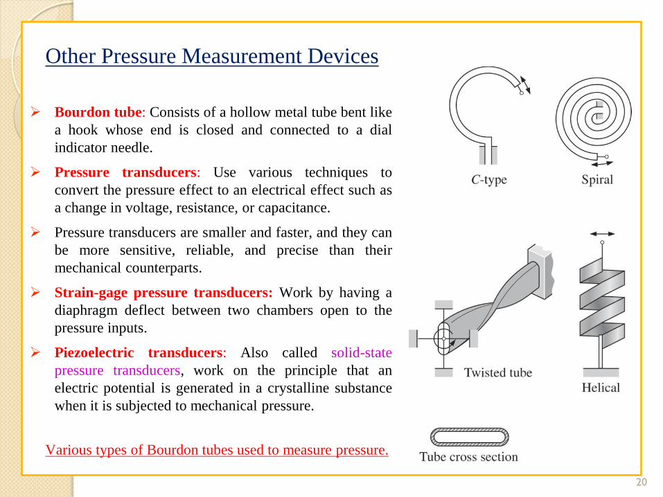
Other Pressure Measurement Devices
Bourdon tube: Consists of a hollow metal tube bent like
a hook whose end is closed and connected to a dial
indicator needle.
Pressure transducers: Use various techniques to
convert the pressure effect to an electrical effect such as
a change in voltage, resistance, or capacitance.
Pressure transducers are smaller and faster, and they can
be more sensitive, reliable, and precise than their
mechanical counterparts.
Strain-gage pressure transducers: Work by having a
diaphragm deflect between two chambers open to the
pressure inputs.
Piezoelectric transducers: Also called solid-state
pressure transducers, work on the principle that an
electric potential is generated in a crystalline substance
when it is subjected to mechanical pressure.
Various types of Bourdon tubes used to measure pressure.
20

THE BAROMETER AND ATMOSPHERIC PRESSURE:
Atmospheric pressure is measured by a device called a barometer; thus, the
atmospheric pressure is often referred to as the barometric pressure.
A frequently used pressure unit is the standard atmosphere, which is defined as the
pressure produced by a column of mercury 760 mm in height at 0°C (Hg = 13,595
kg/m3) under standard gravitational acceleration (g = 9.807 m/s2).
The basic barometer.
The length or the cross-
sectional area of the
tube has no effect on
the height of the fluid
column of a barometer,
provided that the tube
diameter is large
enough to avoid
surface tension
(capillary) effects.
21
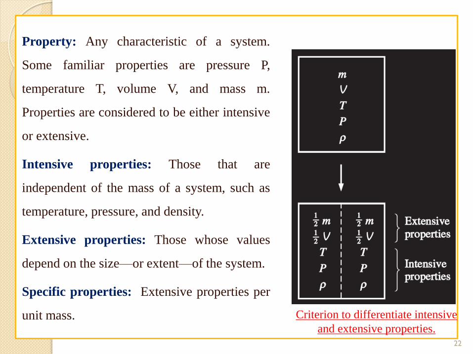
Property: Any characteristic of a system.
Some familiar properties are pressure P,
temperature T, volume V, and mass m.
Properties are considered to be either intensive
or extensive.
Intensive properties: Those that are
independent of the mass of a system, such as
temperature, pressure, and density.
Extensive properties: Those whose values
depend on the size—or extent—of the system.
Specific properties: Extensive properties per
unit mass. Criterion to differentiate intensive
and extensive properties.
22

The ratio of the extensive property to the mass is called the specific value of that
property .
specific volume, v = V/m = 1/ ρ ( ρ is the density)
specific internal energy, u = U/m
Similarly, the molar properties are defined as the ratios of the properties to the
mole number (N) of the substance
Molar volume =v = V/N
Molar internal energy = u= U/N
23
PROCEDURE:
Students are advised to deeply observe the apparatus operation during
experimentation and then write down the procedure for the experiment in their
own words.
24

OBSERVATIONS AND CALCULATIONS
25
No. of
Obs.
Pressure before
distribution
P1 P2 P3 P4 P5 P6 Pressure after
distribution
--- Bars Bars Bars Bars Bars Bars Bars Bars
1. 3.0
2. 2.5
3. 2.0
4. 1.5
5. 1.0

Results:
Students are advised to deeply check that either all the gages are showing the
same values or not. If all the values are same the what it is showing? Similarly if
all the values in all gages are not same that what that are showing, and why all
that are not same.
Comments:
This is the most important part of your experimental work. In this portion of your
experiment you give the comments about your observations, calculations,
experimental results etc. If there are some variations in experimental results then
discuss why they are, and how it can be removed. Also observe that what were
the errors generated during due to environmental effects, human error or by any
other source. Keep in mind every student has different mind, different thinking
and different approach to observe the things.
26

Applied Thermodynamics
Experiment_02_MT_234
Instructor: Mr. Adnan Qamar
Mechanical Engineering Department
27
Experiment No. 02: Calibration of Bourdon Manometer Gauge and
determination of Hysteresis curve.
Apparatus: Dead Weight Calibrator, Set of Masses
28

29

PROCESS DIAGRAM AND ELEMENTS ALLOCATION
30
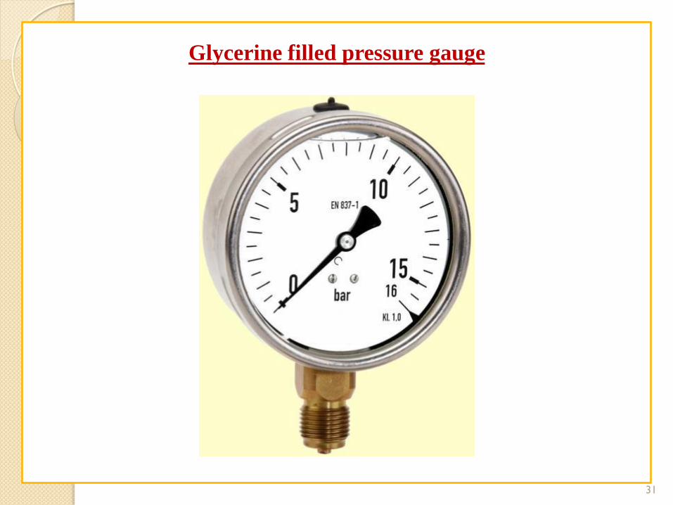
Glycerine filled pressure gauge
31

APPARATUS DESCRIPTION:
This unit enables a wide range of investigations and studies into pressure
measurement techniques, using Bourdon type pressure gauges to understand
the operation the characteristic of the devices, and to study the principles of
calibration and to do practical exercises and experiments about it.
Pressure Measurement and Calibration Unit is designed to study pressure and
how different methods and techniques can be used to measure this variable.
This unit introduces students to pressure, pressure scales and common devices
available to measure pressure.
It comprises a dead-weight pressure calibrator to generate a number of
predetermined pressures, connected to a Bourdon type manometer to allow
their characteristics, including accuracy and linearity, to be determined.
32

APPARATUS DESCRIPTION:
Using the dead-weight pressure calibrator different fixed pressures are
generated for calibrating the measuring elements. The dead-weight pressure
calibrator consists of a precision piston and cylinder with a set of weights.
The Bourdon type manometer is mounted on a manifold block with a separate
reservoir to contain the water.
Valves allow for easy priming, restricted flow of water to demonstrate the
application of damping and the connection of alternative devices for
calibration.
33

APPARATUS SPECIFICATIONS:
Bourdon gauge with dead-weight calibrator module:
Anodized aluminum structure and panel in painted steel (epoxy paint), and
main metallic elements in stainless steel.
Diagram in the panel with similar distribution to the elements in the real unit.
Dead-weight calibrator consists of a piston, with is free to move vertically, in
cylinder. Flexible hose connects the cylinder with the Bourdon pressure gauge.
A set of weights are included.
Bourdon type gauge with internal mechanism clearly visible through the
transparent dial.
The module can be leveled with the help of adjustable feet.
34

35
Calibration:
It is defined as the process of comparison of specific values of input and output
of instrument with the corresponding reference standards.
Concept Structure:
Calibration
Process of comparison of specific values of input
and output of instrument
Corresponding reference standard
With
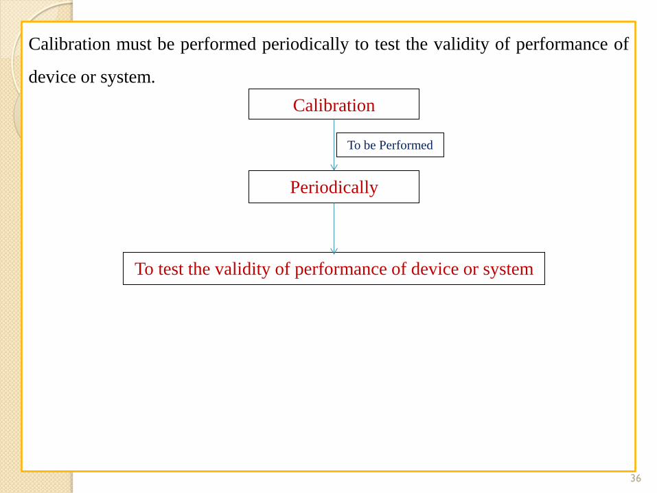
Calibration must be performed periodically to test the validity of performance of
device or system.
36
Calibration
Periodically
To test the validity of performance of device or system
To be Performed

BOURDON TUBE
Bourdon Tubes are known for its very high range of differential pressure
measurement in the range of almost 100,000 psi (700 MPa). It is an elastic
type pressure transducer.
The device was invented by Eugene Bourdon in the year 1849. The basic idea
behind the device is that, cross-sectional tubing when deformed in any way
will tend to regain its circular form under the action of pressure.
The bourdon pressure gauges used today have a slight elliptical cross-section
and the tube is generally bent into a C-shape or arc length of about 27 degrees.
The detailed diagram of the bourdon tube is shown below.
37

BOURDON TUBE
38
BOURDON TUBE
As seen in the figure, the pressure input is given to a socket which is soldered
to the tube at the base. The other end or free end of the device is sealed by a
tip. This tip is connected to a segmental lever through an adjustable length
link. The lever length may also be adjustable. The segmental lever is suitably
pivoted and the spindle holds the pointer as shown in the figure. A hair spring
is sometimes used to fasten the spindle of the frame of the instrument to
provide necessary tension for proper meshing of the gear teeth and thereby
freeing the system from the backlash.
Any error due to friction in the spindle bearings is known as lost motion. The
mechanical construction has to be highly accurate in the case of a Bourdon
Tube Gauge. If we consider a cross-section of the tube, its outer edge will
have a larger surface than the inner portion. The tube walls will have a
thickness between 0.01 and 0.05 inches.
39

BOURDON TUBE
Working:
As the fluid pressure enters the bourdon tube, it tries to be reformed and
because of a free tip available, this action causes the tip to travel in free space
and the tube unwinds. The simultaneous actions of bending and tension due to
the internal pressure make a non-linear movement of the free tip.
This travel is suitable guided and amplified for the measurement of the
internal pressure. But the main requirement of the device is that whenever the
same pressure is applied, the movement of the tip should be the same and on
withdrawal of the pressure the tip should return to the initial point.
40

BOURDON TUBE
Working:
A lot of compound stresses originate in the tube as soon as the pressure is
applied. This makes the travel of the tip to be non-linear in nature. If the tip
travel is considerably small, the stresses can be considered to produce a linear
motion that is parallel to the axis of the link. The small linear tip movement is
matched with a rotational pointer movement. This is known as multiplication,
which can be adjusted by adjusting the length of the lever.
For the same amount of tip travel, a shorter lever gives larger rotation. The
approximately linear motion of the tip when converted to a circular motion
with the link-lever and pinion attachment, a one-to-one correspondence
between them may not occur and distortion results. This is known as
angularity which can be minimized by adjusting the length of the link.
41

BOURDON TUBE
Working:
Other than C-type, bourdon gauges can also be constructed in the form of a
helix or a spiral. The types are varied for specific uses and space
accommodations, for better linearity and larger sensitivity. For thorough
repeatability, the bourdon tubes materials must have good elastic or spring
characteristics.
The surrounding in which the process is carried out is also important as
corrosive atmosphere or fluid would require a material which is corrosion
proof. The commonly used materials are phosphor-bronze, silicon-bronze,
beryllium-copper, inconel, and other C-Cr-Ni-Mo alloys, and so on.
42

BOURDON TUBE
Working:
In the case of forming processes, empirical relations are known to choose the
tube size, shape and thickness and the radius of the C-tube. Because of the
internal pressure, the near elliptic or rather the flattened section of the tube
tries to expand as shown by the dotted line in the figure below (a). The same
expansion lengthwise is shown in figure (b). The arrangement of the tube,
however forces an expansion on the outer surface and a compression on the
inner surface, thus allowing the tube to unwind. This is shown in figure (c).
43

BOURDON TUBE
Expansion of Bourdon Tube Due to Internal Pressure
44

BOURDON TUBE
Working:
Like all elastic elements a bourdon tube also has some hysteresis in a given
pressure cycle. By proper choice of material and its heat treatment, this may
be kept to within 0.1 and 0.5 percent of the maximum pressure cycle.
Sensitivity of the tip movement of a bourdon element without restraint can be
as high as 0.01 percent of full range pressure reducing to 0.1 percent with
restraint at the central pivot.
45

PROCEDURE:
Students are advised to deeply observe the apparatus operation during
experimentation and then write down the procedure for the experiment in their
own words.
46
OBSERVATIONS AND CALCULATIONS
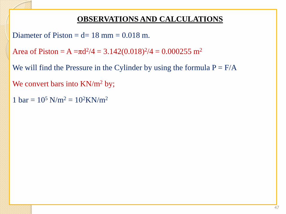
Diameter of Piston = d= 18 mm = 0.018 m.
Area of Piston = A =πd2/4 = 3.142(0.018)2/4 = 0.000255 m2
We will find the Pressure in the Cylinder by using the formula P = F/A
We convert bars into KN/m2 by;
1 bar = 105 N/m2 = 102KN/m2
47
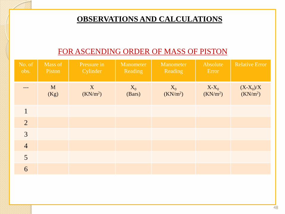
OBSERVATIONS AND CALCULATIONS
FOR ASCENDING ORDER OF MASS OF PISTON
48
No. of
obs.
Mass of
Piston
Pressure in
Cylinder
Manometer
Reading
Manometer
Reading
Absolute
Error
Relative Error
--- M
(Kg)
X
(KN/m2)
X0
(Bars)
X0
(KN/m2)
X-X0
(KN/m2)
(X-X0)/X
(KN/m2)
1
2
3
4
5
6

OBSERVATIONS AND CALCULATIONS
FOR DESCENDING ORDER OF MASS OF PISTON
49
No. of
obs.
Mass of
Piston
Pressure in
Cylinder
Manometer
Reading
Manometer
Reading
Absolute
Error
Relative Error
--- M
(Kg)
X
(KN/m2)
X0
(Bars)
X0
(KN/m2)
X-X0
(KN/m2)
(X-X0)/X
(KN/m2)
1
2
3
4
5
6

OBSERVATIONS AND CALCULATIONS
AVERAGE OF ASCENDING & DESCENDING VALUES OF MASS OF PISTON
50
No. of
obs.
Mass of
Piston
Pressure in
Cylinder
Manometer
Reading
Manometer
Reading
Absolute
Error
Relative Error
--- M
(Kg)
X
(KN/m2)
X0
(Bars)
X0
(KN/m2)
X-X0
(KN/m2)
(X-X0)/X
(KN/m2)
1
2
3
4
5
6

GRAPH:
Graph between absolute error in a function of the real pressure in the manometer.
Graph between relative error in a function of the real pressure in the manometer.
DETERMINATION OF HYSTERISIS CURVE
Hysteresis is the dependence of a system not only on its current environment but also on
its past environment. This dependence arises because the system can be in more than one
internal state. To predict its future development, either its internal state or its history must
be known.[1] If a given input alternately increases and decreases, the output tends to form a
loop as in the figure. However, loops may also occur because of a dynamic lag between
input and output. Often, this effect is also referred to as hysteresis, or rate-dependent
hysteresis. This effect disappears as the input changes more slowly, so many
experts[who?] do not regard it as true hysteresis.
51

DETERMINATION OF HYSTERISIS CURVE
Hysteresis occurs in ferromagnetic materials and ferroelectric materials, as well as
in the deformation of some materials in response to a varying force. In natural
systems hysteresis is often associated with irreversible thermodynamic change.
Many artificial systems are designed to have hysteresis: for example,
in thermostats hysteresis is produced by positive feedback to avoid unwanted
rapid switching. Hysteresis has been identified in many other fields,
including economics and biology.
52

DETERMINATION OF HYSTERISIS CURVE
Draw a graph between real pressure in KN/m2 and manometer pressure in
KN/m2 for ascending and descending readings. If a loop is formed in the graph
this means hysteresis take place.
53

DETERMINATION OF HYSTERISIS CURVE
54

Results:
Students are advised to deeply check that either the applied pressure on the piston
comprises the pressure shown on the Bourdon Pressure Gauge. If both of the
values are same then tell what it is showing of. If there is a difference in the actual
pressure and the pressure shown on the gauge then why does it so… What are the
reasons of it. What are your conclusions from this experiment.
Comments:
This is the most important part of your experimental work. In this portion of your
experiment you give the comments about your observations, calculations,
experimental results etc. If there are some variations in experimental results then
discuss why they are, and how it can be removed. Also observe that what were
the errors generated during due to environmental effects, human error or by any
other source. Keep in mind every student has different mind, different thinking
and different approach to observe the things.
55