applied surface science - additive manufacturing lab · yang et al. / applied surface science 402...
TRANSCRIPT

F
Si
Ya
b
a
ARRAA
KSMEV
1
tt[mooctcstpt[sepc
h0
Applied Surface Science 402 (2017) 400–409
Contents lists available at ScienceDirect
Applied Surface Science
journa l h om epa ge: www.elsev ier .com/ locate /apsusc
ull Length Article
tructural coloration of metallic surfaces with micro/nano-structuresnduced by elliptical vibration texturing
ang Yang a, Yayue Pan b, Ping Guo a,∗
Department of Mechanical and Automation Engineering, The Chinese University of Hong Kong, Hong Kong, ChinaDepartment of Mechanical and Industrial Engineering, University of Illinois at Chicago, Chicago, IL, USA
r t i c l e i n f o
rticle history:eceived 8 October 2016eceived in revised form 8 December 2016ccepted 4 January 2017vailable online 5 January 2017
eywords:
a b s t r a c t
Creating orderly periodic micro/nano-structures on metallic surfaces, or structural coloration, for controlof surface apparent color and optical reflectivity has been an exciting research topic over the years. Thedirect applications of structural coloration include color marking, display devices, and invisibility cloak.This paper presents an efficient method to colorize metallic surfaces with periodic micro/nano-gratingsusing elliptical vibration texturing. When the tool vibration is coupled with a constant cutting velocity,controlled periodic ripples can be generated due to the overlapping tool trajectory. These periodic ripples
tructural colorationicro-grating
lliptical vibration texturingibration-assisted machining
with a wavelength near visible spectrum can act as micro-gratings to introduce iridescent colors. Theproposed technique also provides a flexible method for color marking of metallic surfaces with arbitrarypatterns and images by precise control of the spacing distance and orientation of induced micro/nano-ripples. Theoretical analysis and experimental results are given to demonstrate structural coloration ofmetals by a direct mechanical machining technique.
© 2017 Published by Elsevier B.V.
. Introduction
Surface micro/nano-structures have been widely studiedo create functional surfaces for enhanced performance inheir tribological, biological, mechanical, and optical properties1]. Specifically, creating orderly periodic near-subwavelength
icro/nano-structures on metallic surfaces, or structural col-ration, serves as a physical process for controlling the color andptical reflectivity of metals, which has a variety of potential appli-ations, such as color marking, display devices, and invisibility cloakechnology [2–4]. Structural coloration has been attributed to theomplex interactions between light waves and surface micro/nano-tructures, which has been widely observed in nature, such ashe color change of Morpho butterflies and iridescent colors ofeacocks’ feathers [5]. The structural coloration can be attributedo a range of photonic mechanisms, including plasmonic effects6,7] and diffraction grating effects. The diffraction-grating inducedtructural coloration is unique such that it renders an iridescent
ffect, or the apparent color is dependent on the viewing angle. Thisaper focuses on the manufacturing and evaluation of structuraloloration based on the diffraction grating effect.∗ Corresponding author.E-mail address: [email protected] (P. Guo).
ttp://dx.doi.org/10.1016/j.apsusc.2017.01.026169-4332/© 2017 Published by Elsevier B.V.
Diffraction gratings have been traditionally manufactured byusing mechanical ruling [8] and interference lithography [9]. Thesemethods are used to produce extremely uniform and high qual-ity master molds of diffraction gratings for mass production oftheir replicates. However, these traditional methods are not able tocreate complex colorful patterns. More recently, researchers haveutilized femtosecond lasers for structural coloration by utilizingthe laser induced periodic surface structures (LIPSSs). Vorobyevand Guo [10] used a femtosecond laser to render aluminum sur-faces to gold, black and grey by structural coloration. By a similartechnique, laser-induced periodic surface structures covered withnano-particles were generated on aluminum surfaces resulting inan iridescent effect of aluminum [10]. Ahsan et al. [11] have pre-pared colorful stainless steel surfaces with periodic micro-holesand micro/nano-ripples induced by femtosecond laser impulses.The orientation of LIPSSs is controlled by changing the laser polar-ization direction to produce different apparent colors for colormarking [2].
The laser induced orderly surface patterns are spontaneouslygenerated during laser irradiation due to the laser-matter inter-action. Average spatial intervals of the closely arranged LIPSSsproduced by a femtosecond laser locate in the visible spectrum.
The interval length of LIPSSs is subjected to the laser wavelength,average fluence, pulse frequency, scanning speed, etc. [12,13].Structural coloration using LIPSSs can be explained intuitively by
Y. Yang et al. / Applied Surface Science 402 (2017) 400–409 401
Fig. 1. Process principle: (a) intuitive idea of cutting depth modulation; (b) proposed elliptical vibration texturing using an overlapping tool trajectory.
Fig. 2. (a) Geometry definition of vibration-induced cusps and (b) schematic of micro/nano-ripples induced by elliptical vibration texturing process.
ts and
tntLdtt
d
wtd
vd
�
Fig. 3. (a) Response vibration displacemen
wo different factors [13]: (1) the color effect of laser inducedano-particles on top of the micro-gratings, which accounts forhe non-iridescent colors; and (2) the grating diffraction effect ofIPSSs, which accounts for the iridescent colors. Iridescent colorsue to the periodic structures can be described by the grating equa-ion, which states the relationship between the grating spacing andhe angles of diffracted light:
(sin�i + sin�m
)= m� (1)
here d is the grating spacing; m is an integer indicating the diffrac-ion order; �i and �m are the light incident angle and the angle ofiffracted beams of order m, respectively; and � is the wavelength.
If the incident white light is perpendicular to the surface, theiewing angle of a certain color of wavelength, �, is given by the
iffracted angle maxima, which is given by:m = arcsin(m�
d
)(2)
(b) elliptical trajectory of the cutting tool.
The laser induced periodic ripples, though are highly repro-ducible, suffer from several drawbacks. Firstly, the ripple densityor grating spacing, d, which specifies the diffracting resolution, issubjected to the wavelength of laser source. In addition, it is diffi-cult to predict and control the grating spacing and hence limit thetechnology to produce micro/nano-gratings with arbitrary spac-ing. Secondly, the produced micro/nano-gratings are semi-regular,which deteriorates the diffraction efficiency, or the color effect.Lastly, the high cost of a femtosecond laser system makes thetechnology difficult to be adopted by the industry. The above-mentioned problems motivate this paper, which is to develop anefficient manufacturing process with a low-cost setup to producecontrollable periodic ripples on metallic surfaces for improvingtheir appearance and optical properties.
In this paper, we demonstrate the fast creation of micro/nano-
ripples with wavelength in the UV light, visible and infraredspectrum (300 nm–1300 nm) on metallic surfaces using ellipticalvibration texturing, which is a vibration-assisted mechanical cut-ting process. Original mono-color of metallic surfaces have been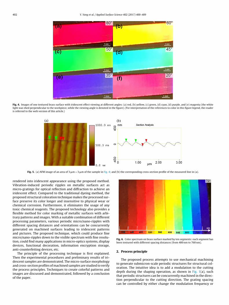
402 Y. Yang et al. / Applied Surface Science 402 (2017) 400–409
Fig. 4. Images of one textured brass surface with iridescent effect viewing at different angles: (a) red, (b) yellow, (c) green, (d) cyan, (d) purple, and (e) magenta (the whitelight was shed perpendicular to the workpiece, while the viewing angle is denoted in the figure). (For interpretation of the references to color in this figure legend, the readeris referred to the web version of this article.)
; and (b) the corresponding cross-section profile of the measured line in (a).
rVmipfctfltpdgamtda
Tdatio
Fig. 5. (a) AFM image of an area of 3 �m × 3 �m of the sample in Fig. 4
endered into iridescent appearance using the proposed method.ibration-induced periodic ripples on metallic surfaces act asicro-gratings for optical reflection and diffraction to achieve an
ridescent effect. Compared to the traditional dyeing method, theroposed structural coloration technique makes the processed sur-
ace preserve its color longer and insensitive to physical wear orhemical corrosion. Furthermore, it eliminates the usage of anyoxic chemical reagents. The proposed technology also provides aexible method for color marking of metallic surfaces with arbi-rary patterns and images. With a suitable combination of differentrocessing parameters, various periodic micro/nano-ripples withifferent spacing distances and orientations can be concurrentlyenerated on machined surfaces leading to iridescent patternsnd pictures. The proposed technique, which could produce fineicro/nano-ripples down to the visible spectrum with fine resolu-
ion, could find many applications in micro-optics systems, displayevices, functional decoration, information encryption storage,nti-counterfeiting devices, etc.
The principle of the processing technique is first explained.hen the experimental procedures and preliminary results of iri-escent samples are demonstrated. The micro-surface morphologynd cross-section profiles of machined samples are studied to verify
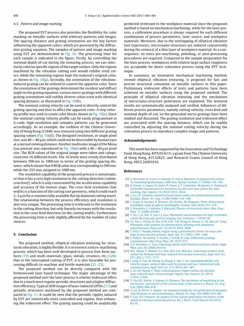
he process principles. Techniques to create colorful patterns andmages are discussed and demonstrated, followed by a conclusionf the paper.Fig. 6. Color spectrum on brass surface marked by ten segments: each segment hasbeen textured with different spacing distances (from 400 nm to 760 nm).
2. Process principle
The proposed process attempts to use mechanical machiningto generate submicron-scale periodic structures for structural col-oration. The intuitive idea is to add a modulation to the cutting
depth during the shaping operation, as shown in Fig. 1(a), suchthat periodic structures can be concurrently machined in the direc-tion perpendicular to the cutting direction. The grating spacingcan be controlled by either change the modulation frequency or
Y. Yang et al. / Applied Surface Sc
Fs
tsotentpi1wuimciinvffstDumsp
fcFtfdcuto1ttc
ig. 7. Iridescent effect achieved on different materials: (a) aluminum alloy, (b)tainless steel, and (c) copper.
he cutting velocity for color marking of complex patterns. Thisimple concept, however, has not been reported for generationf sub-micron diffraction gratings in the literature mainly due towo reasons. First, there is no proper actuator which could gen-rate fast enough modulation in the depth-of-cut direction. Theominal cutting velocity of the cutting tool is directly propor-ional to the modulation frequency. It not only determines therocess efficiency, but also has a major impact on the machin-
ng quality. Commercial fast tool servos, which could generate fastD actuation, usually have a bandwidth in the kilohertz range. Ife would like to generate diffraction gratings of 500 nm spacing
sing a 1 kHz motion, the corresponding nominal cutting veloc-ty would be 0.5 mm/s. The efficiency would be unsatisfactory, but
ore importantly the low cutting velocity may prevent a stableutting condition and significantly deteriorate the surface qual-ty. Second, mechanical machining conventionally is not favoredn processing nano-scale features due to the minimum chip thick-ess effect [14,15]. When the uncut chip thickness is below a criticalalue, which is called the minimum chip thickness, no chip will beormed and the material will flow beneath the tool. Even an ultra-ast actuator is available, the uncut chip thickness when machiningub-micron periodic structures will fall below the minimum chiphickness, so that a stable cutting process cannot be established.ue to the above-stated two reasons: (1) technical difficulties inltra-fast tool actuation and (2) minimum chip thickness effect inicro-cutting mechanics, the principle of cutting depth modulation
hown in Fig. 1(a) has not been adopted for generating sub-microneriodic structures.
In this paper, elliptical vibration texturing (EVT) is proposedor fast generation of sub-micron periodic gratings for structuraloloration on metallic surfaces. The process principle is shown inig. 1(b). When two-dimensional ultrasonic vibration is appliedo the cutting tool, periodic cusps will be left on processed sur-aces due to the overlapping tool trajectory. This method has beenemonstrated for the first time for structural coloration, whichould address the aforementioned difficulties. Two-dimensionalltrasonic vibration (28 kHz) was applied to the cutting tool, sohat 28 thousand periodic structures could be generated per sec-nd; and the nominal cutting velocity would be increased to
4 mm/s for the same 500 nm spacing gratings. More importantly,he two-dimensional vibration would result in the overlapping toolrajectories and the naturally formed periodic cusps left on the pro-ess surface. The actual uncut chip thickness thus would be muchience 402 (2017) 400–409 403
greater than the micro-scale feature size as well as the minimumchip thickness. A stable cutting process would be established ratherthan a ploughing process.
As shown in Fig. 2(a), the machining marks, or periodic cusps, arein the form of orderly ripples, whose orientation is perpendicular tothe cutting direction. The ripple spacing can be precisely controlled,which is determined by the ratio of nominal cutting velocity to toolvibration frequency; it is given by:
d = (2��)/ω (3)
where v is the nominal tool cutting velocity; and the ω is the toolvibration frequency.
The height of cusps is associated with a process-dependent vari-able, denoted as the “overlapping ratio” of the tool path. To describethe intersection area of the tool path, one can define the overlappingratio as the maximal vibration velocity in the cutting direction (Xaxis) divided by the nominal cutting velocity. Intuitively, the cuspheight is inversely related to the overlapping ratio, and positivelyrelated to the ripple spacing distance, d. In addition, the overlappingratio is also associated with the tool vibration amplitude in the tan-gential direction for a given spacing distance. Typical height valuesof vibration-induced micro/nano-ripples in the UV to near-infraredspectrum lie in the range of several tens of to several hundredsof nanometers. The coordinates of the cusps can be analyticallydetermined according to Fig. 2(a):
Ax cos
(�1 + �2
2
)sin
(�1 − �2
2
)+v(�1 − �2
)2ω
= 0 (4)
where Ax is the tool vibration amplitude in cutting direction; �1 and�2 are two particular angular positions of the tool tip correspondingto the coordinates of the cusps, whose values are between 0 and 2�.Their particular values can be solved numerically. Then the heightof the vibration induced cusps is given by:
h = Ay(
1 − |sin(�1 + ϕ|)
(5)
where Ay is tool vibration amplitude in the cutting depth direction.By sequential cuttings in parallel lines as shown in Fig. 2(b),
the vibration-induced ripples are connected to form incessant longedges due to the overlapping of cutting areas in the cross-feeddirection. Periodic micro/nano-ripples with a wavelength from UVto near-infrared spectrum have been concurrently generated onmachined surfaces using the proposed EVT process. The geome-try and spacing distance of the ripples can be precisely controlledby adjusting the process parameters, so the generated ripples canact as micro/nano-gratings for optical reflection and diffraction toachieve an iridescent effect.
3. Experimental setup and details
The key component in the elliptical vibration texturing process[16,17] is a tertiary motion generator capable of producing ellipticalvibration at the tool tip. The device was carefully constructed topossess two orthogonal vibration modes at an identical ultrasonicfrequency. Then an elliptical tool trajectory was obtained due tothe coupled resonant modes when the device was driven at thecoupled resonant frequency. Vibration amplitude up to 10 �m atthe ultrasonic frequency in each direction (cutting and depth-of-cut directions) can be achieved. More detailed descriptions of thedesign and principle of the resonant vibrator can be found in ourprevious work [18].
Since the induced ripples were at the scale of several hundred
nanometers, a commercial single crystal diamond cutting insertwas mounted on the tertiary motion generator for the texturingprocess. The rake and clearance angles of the cutting insert are0◦ and 12◦, while the nose radius is 509 �m. The high-voltage
404 Y. Yang et al. / Applied Surface Science 402 (2017) 400–409
F utting(
eeT±o
ig. 8. Five segments with different colors viewed at 70 ◦ processed with different ca) 300 nm, (b) 600 nm, (c) 750 nm, (d) 1000 nm, and (e) 1300 nm.
xcitation signals were generated by a two-channel function gen-
rator and then amplified by a piezo amplifier (TREK PZD350A).he amplifier is capable of producing ±350 V bipolar voltage and200 mA bipolar current. The tertiary motion generator was fixedn an Aerotech linear actuator (ACT115DL), which provides cuttingvelocities; and SEM micrographs of the corresponding surface micro-topography:
motion (X axis) during the texturing process. The resolution and
repeatability of the linear actuator are 10 nm and 1 �m, respec-tively. In order to ensure the optimal vibration performance of thecutting tool, two capacitance displacement sensors from Microsense(Model 5504) were adopted and integrated to the machine setup
Y. Yang et al. / Applied Surface Sc
Fig. 9. (a–d) Iridescent effect achieved with the same cutting velocity, cross feedao
tcNt
sps7os
epucmnratwweaadtt
ctmppnaoctPddtuouT
cutting nature can be applied to materials with different machin-
nd different nominal depth-of-cuts viewed from different angles. Nominal depth-f-cut: (1) −3 �m; (2) 0 �m; and (3) 3 �m.
o monitor the dynamic vibration displacement responses of theutting tool. The measured response signals were transmitted to aI data acquisition card (NI DAQ PCIe-6361) for further processing
hrough a LabVIEW interface at a sampling rate of 1 MHz.The workpiece was screwed on an Aerotech three-axis motion
tage (ANT130-060-L) through a base plate adaptor. Processingarameters of depth-of-cut (Y axis) and cross-feed (Z axis) wereet by the three-axis motion stage, which has 1 nm resolution and5 nm repeatability for each axes. The whole setup was stationedn a vibration isolation table and controlled by an A3200 controlystem.
A pre-tuning process was necessary for the tertiary motion gen-rator to achieve the ideal vibration performance for the texturingrocess. Meanwhile, the vibration performance should also be eval-ated from time to time during the texturing process to ensure theonsistency of tool vibration trajectories. To this end, the tertiaryotion generator was carefully calibrated to the designed reso-
ant operation mode. Vibration displacements of the tool tip wereecorded using two capacitance displacement sensors in the cuttingnd depth-of-cut directions. By means of a frequency sweep test,he coupled resonant frequency of the tertiary motion generatoras found at 28.0 kHz. The applied sinusoidal voltage amplitudesere set at ±300 V, while the phase difference between the two
xcitation signals was set at 0◦ to achieve the largest vibrationmplitude in the depth-of-cut direction. The 2D tool trajectorieslong with the tool displacements in the cutting and depth-of-cutirections are plotted in Fig. 3. The peak-to-peak vibration ampli-udes in the depth-of-cut and cutting directions were determinedo be 12.0 �m and 4.5 �m.
Using the driving parameters obtained from the pre-tuning pro-ess, the cutting tool can vibrate along an elliptical trajectory forhe following coloration process. It should be noted that specific
icro/nano-structures are determined by the excitation signals,rocess parameters and cutting tool geometry, etc. The particularrocess parameters, e.g. nominal cutting velocity, cross feed, nomi-al depth-of-cut, require careful considerations, since the geometrynd the vibration frequency of the tool were fixed during the col-ration process. As discussed in the principle section, nominalutting velocity plays a key role in the induced ripple spacing dis-ance and overall grating effect of the colorized metallic samples.articular cross feeds are selected to link the cusps in the cross-feedirection to form incessant ripples, while the nominal depth-of-cutetermines the material removal rate and cutting force. Followinghe texturing process, all the machined samples were cleaned in anltrasonic cleaner with acetone at 50 ◦C for 10 min. Color pictures
f the textured samples were shot under different observing anglessing an iPhone 6s camera under a halogen lamp as the light source.hen the height profile of vibration-induced structures was investi-ience 402 (2017) 400–409 405
gated with a Multimode atomic force microscope (AFM) in contactmode, while the surface morphology of textured structures wasstudied using a JOEL scanning electronic microscope (JSM-7800F)with a LED detector and acceleration voltage of 5 kV.
4. Results and discussions
4.1. Process principle verfication
Preliminary iridescent effects have been achieved on brass sur-faces with a nominal cutting velocity of 14.0 mm/s, cross feedof 50 �m and 0 depth-of-cut, as shown in Fig. 4. An area of10 mm × 3 mm has been textured within 3 min due to the ultra-sonic vibration frequency of the tool. As seen from the texturedresults, the brass surface exhibited different vivid colors with-out any pigment or coating material. Furthermore, the apparentcolor varied from one viewing angle to another as demonstratedin Fig. 4(a)–(f). In essence, these iridescent effects are attributed tothe micro/nano-ripples induced by the elliptical vibration texturingprocess. Periodic vibration-induced micro/nano-ripples uniformlydistributed on the brass surface act as micro-gratings resultingin reflection and diffraction effects. Governed by the diffractiongrating equation, the apparent color is determined by the spac-ing distance, viewing angle, and incident light angle. For a givenconstant spacing distance and a normal incident angle, the whitelight with different wavelengths is diffracted along different direc-tions leading to an iridescent effect of metallic surfaces. Light with alonger wavelength appears at a larger diffraction angle, while lightwith a shorter wavelength appears at a smaller diffraction angle.
In addition, the overall grating effect mainly depends on thegrating geometry and grating density. A larger grating density andhigher aspect-ratio contribute to a finer grating resolution and abetter iridescent effect. Both of the grating density and geometrycan be controlled by the proposed technique by adjusting the pro-cess parameters. The grating geometry can be partially controlledby the design of tool geometry and fine tuning of the tool vibrationtrajectory. Fig. 5(a) shows a 3D image of the micro/nano-ripples dis-tributed on the sample in Fig. 4 measured with an AFM, while thecorresponding cross-section profile is plotted in Fig. 5(b). The pro-file resembles the geometry of blazed gratings, and has an averageheight of 130 nm. On the other hand, the grating density, or grat-ing spacing, can be more easily controlled by adjusting the nominalcutting velocity and is the main parameter to study in this work.The grating density in the presented sample shown in Fig. 4 can becalculated to be 2000 lines/mm, and was measured to be 470 nmas shown in Fig. 5(b).
In order to find out the range of color which can be reproducedby the proposed technique, a color palette was generated with tensegments whose ripple spacing was from 400 nm to 760 nm withan increment of 40 nm. As shown in Fig. 6, when the workpiecewas viewed at 70◦, the whole visible spectrum can be identified. Itshould be noted that the spacing distance of generated micro/nano-ripples is not limited to the visible spectrum for achieving aniridescent effect. However, larger spacing distances lead to a lowergrating resolution, and a rainbow color effect due to a smaller angu-lar dispersion; while smaller spacing distances lead to a uniformcolor effect due to a greater angular dispersion.
We have demonstrated the coloration capability of the proposedmethod and the color pallet generation only on brass workpieces. Infact, the elliptical vibration texturing process due to its intermittent
ability, as illustrated in Fig. 7. Surfaces with iridescent effects havebeen achieved on different materials, such as aluminum alloy,stainless steel and copper. However, the influences of material

406 Y. Yang et al. / Applied Surface Science 402 (2017) 400–409
F turingv
pm
4i
ii
ig. 10. Pattern and image marking on brass surfaces: (a) patterns by selective texelocity profile; (d) the university emblem; (e) the Mona Lisa portrait.
roperties on the iridescent effect and tool wear are yet to be deter-ined and are out of the scope of this work.
.2. Study of the influences of process parameters on theridenscent effect
We performed additional experiments to investigate the spac-ng distance range capable of achieving iridescent effects and thenfluence of grating morphologies on the iridescent effect. As ana-
; (b) color variation by changing the grating orientation; (c) color blocks by a step
lyzed in the principle section, spacing distance of the periodicmicro/nano-ripples is determined by the ratio of nominal cuttingvelocity to the tool vibration frequency. The vibration frequency isfixed with the resonant frequency of the designed tool and there-fore kept as a constant for all texturing experiments. The spacingdistance of vibration-induced ripples then can be tuned by choosing
a suitable nominal cutting velocity.As shown in Fig. 8, nominal cutting velocities from the first tothe fifth segment were 8.4 mm/s, 16.8 mm/s, 21.0 mm/s, 28.0 mm/s

Y. Yang et al. / Applied Surface Science 402 (2017) 400–409 407
Fig. 11. Comparison between (a) LIPSSs [11] and (b) periodic structures generated by EVT.
Table 1Process parameters for the study of grating spacing.
akeDpTfiraoeampfiio
3t1tTmt
ai
nd 36.4 mm/s, respectively. The cross feed and depth-of-cut wereept the same for all cases, which were 50 �m and 0 �m. Thexperimental conditions and results are summarized in Table 1.ifferent cutting velocities significantly affected the formation oferiodic micro/nano-ripples leading to various iridescent effects.he spacing distances of the vibration-induced ripples among theve segments located in the UV light, visible, and near-infraredegions of the spectrum. When viewed at 70◦, different segmentsppeared various colors due to the different grating spacing. Inrder to study the influence of grating spacing on the iridescentffect and to validate the principle of EVT, surface morphology ofll the segments has been examined using a scanning electronicicroscope (SEM). As can be seen from Fig. 8(a)–(e), highly regular
eriodic ripples along the cutting direction were clearly identi-ed on the micrographs. In addition, the ripples were connected
n the cross-feed direction forming incessant long edges due to theverlapping of consecutive cuts.
The measured average ripple lengths in each segment were15 nm, 610 nm, 760 nm, 1050 nm and 1300 nm, corresponding tohe theoretical values of 300 nm, 600 nm, 750 nm, 1000 nm and300 nm respectively based on Eq. (3). It can be concluded that theexturing results generally capture the theoretical grating spacing.he minute deviation can be attributed to the choice of measure-ent points, since the periodic length of ripples was varying along
he edge.The ripple edges were connected after sequential cutting par-
llel lines. The cross feeds should be carefully chosen to formncessant long ripples in the cross feed direction. The width of
micro/nano-ripples in each cutting line was determined by the toolgeometry and overall depth-of-cut. If the cross feed was selectedsmaller than the width of micro/nano-ripples, the projection of thetool geometry in the cutting direction from the two consecutivecuts would be overlapping, thus connecting the ripples in the cross-feed direction. If the cross feed was set larger than the width ofmicro/nano-ripples, discontinuous ripples would be formed, lead-ing to a deteriorated iridescent effect. In the present study, for acutting insert of 509 �m nose radius, and 0 depth-of-cut, we chosethe cross feed at 50 �m to keep the balance between efficiency andefficacy.
Nominal depth-of-cut was another factor which might influ-ence the iridescent effect. Due to the mechanism of EVT process,the micro/nano-ripples are concurrently generated on machinedsurfaces. Therefore, within the range of the vibration amplitude,the nominal depth-of-cut has no impact on the final surface tex-tures, thus no effect on the iridescent effect. This conclusion hasbeen verified by our experimental results presented in Fig. 9, wheresegments with different nominal depth-of-cuts (−3 �m, 0 �m, and3 �m) exhibit almost the same color viewed at different observa-tion angles. Here we can introduce a negative nominal depth-of-cutto significantly reduce the amount of removed material, which con-tributes to lower cutting force and reduced effective uncut chipthickness.
4 ace Sc
4
mTituentmoaitags
gitGasssaLsrbtw
scaw2Taittc
5
tpfDc
fpdtppbi
[
[
[
[
[
08 Y. Yang et al. / Applied Surf
.3. Pattern and image marking
The proposed EVT process also provides the flexibility for colorarking on metallic surfaces with arbitrary patterns and images.
he spacing distance and grating orientation are the key factorsnfluencing the apparent colors, which are governed by the diffrac-ion grating equation. The samples of pattern and image markingsing EVT are demonstrated in Fig. 10. The processing time forach sample is indicated in the figure. Firstly, by controlling theominal depth-of-cut during the texturing process, we can selec-ively colorize specific regions of the target surface. Only the regions
achined by the vibration cutting tool would exhibit vivid col-rs, while the remaining regions kept the material’s original color,s shown in Fig. 10(a). Secondly, the orientation of the vibration-nduced grating can be utilized to control the apparent color. Sincehe orientation of the gratings determined the incident and diffractngle on the grating equation, various micro-gratings with differentrating orientations will exhibit diverse colors even with identicalpacing distance, as illustrated in Fig. 10(b).
The nominal cutting velocity can be used to directly control therating spacing and thus to affect the apparent color. A step veloc-ty profile was used to create color blocks shown in Fig. 10(c). Sincehe nominal cutting velocity profile can be easily programmed in-code, high-resolution and complex patterns can be generatedccordingly. As an example, the emblem of the Chinese Univer-ity of Hong Kong (CUHK) was textured using two different gratingpacing values (Fig. 10(d)). The designed resolution, or single pixelize, was 40 × 40 �m, which could not be discernible by human eyest a normal viewing distance. Another multicolor image of the Monaisa portrait was reproduced in Fig. 10(e) with a 40 × 40 �m pixelize. The RGB values of the original image were taken and catego-ized into 16 different levels. The 16 levels were evenly distributedetween 500 nm to 1000 nm in terms of the grating spacing dis-ance, which meant that 0 RGB value was corresponding to 500 nm;hile the 255 was assigned to 1000 nm.
The resolution capability of the proposed process is anisotropic,o that it has a very high resolution in the cutting direction (submi-ron level), which is only constrained by the acceleration capabilitynd accuracy of the motion stage. The cross feed resolution (lineidth) is a function of the cutting tool geometry, which could reach
–3 �m for a commercially available flat tip diamond cutting insert.he relationship between the process efficiency and resolution islso very unique. The processing time is irrelevant to the resolutionn the cutting direction, but only linearly increases with the resolu-ion in the cross feed direction (or the cutting width). Furthermorehe processing time is only slightly affected by the number of colorhoices.
. Conclusion
The proposed method, elliptical vibration texturing for struc-ural coloration, is highly flexible. It is in essence a micro-machiningrocess, which has been well developed to process free-form sur-
aces [19] and multi-materials (glass, metals, ceramics, etc.) [20].ue to the interrupted cutting of EVT, it is also favorable for pro-essing difficult-to-machine and brittle materials [21–23].
The proposed method can be directly compared with theemtosecond laser based technique. The major advantage of theroposed method over the laser process is a better iridescent effectue to a much more regular periodic structures and a higher diffrac-ion efficiency. Typical SEM images of laser-induced LIPSSs [11] and
eriodic structures machined by the proposed method are com-ared in Fig. 11. It could be seen that the periodic ripples inducedy EVT are statistically more controlled and regular, thus enhanc-ng the iridescent effect. The grating spacing could be analytically
[
[
ience 402 (2017) 400–409
predicted irrelevant to the workpiece material since the proposedmethod is based on mechanical machining; while for the laser pro-cess, a calibration procedure is always required for each differentcombination of process parameters, laser source, and workpiecematerials. Moreover, due to the overlapping of elliptical vibrationtool trajectories, micro/nano-structures are induced concurrentlyduring the removal of a thin layer of workpiece material. As a con-sequence, no extra pre-machining, polishing, or post-processingprocedures are required. Compared to the sample preparation forthe laser process, workpieces with relative large surface roughnessare acceptable for direct coloration process using the EVT tech-nique.
In summary, an innovative mechanical machining method,termed elliptical vibration texturing, is proposed for fast andprecise structural coloration on metallic surfaces in this paper.Preliminary iridescent effects of texts and patterns have beenachieved on metallic surfaces using the proposed method. Theprinciple of elliptical vibration texturing and the mechanismof micro/nano-structure generation are explained. The texturedresults are systematically analyzed and verified. Influences of dif-ferent process parameters, namely cutting velocity, cross feed andnominal depth-of-cut, on the generated micro-gratings have beenstudied and discussed. The grating resolution and iridescent effectare associated with the spacing distance, which can be readilycontrolled by adjusting the nominal cutting velocity during thecoloration process to reproduce complex image and patterns.
Acknowledgements
This work has been supported by the Innovation and TechnologyFund, Hong Kong, #ITS/014/15; a grant from The Chinese Universityof Hong Kong, #3132823; and Research Grants Council of HongKong, #ECS 24201816.
References
[1] A. Bruzzone, H. Costa, P. Lonardo, D. Lucca, Advances in engineered surfacesfor functional performance, CIRP Ann. Manuf. Technol. 57 (2008) 750–769.
[2] B. Dusser, Z. Sagan, H. Soder, N. Faure, J.-P. Colombier, M. Jourlin, E. Audouard,Controlled nanostructrures formation by ultra fast laser pulses for colormarking, Opt. Express 18 (2010) 2913–2924.
[3] J. Liu, J.P. Coleman, Nanostructured metal oxides for printed electrochromicdisplays, Mater. Sci. Eng.: A 286 (2000) 144–148.
[4] T. Ergin, N. Stenger, P. Brenner, J.B. Pendry, M. Wegener, Three-dimensionalinvisibility cloak at optical wavelengths, Science 328 (2010) 337–339.
[5] S. Kinoshita, S. Yoshioka, J. Miyazaki, Physics of structural colors, Rep. Prog.Phys. 71 (2008) 076401.
[6] T. Xu, Y.-K. Wu, X. Luo, L.J. Guo, Plasmonic nanoresonators for high-resolutioncolour filtering and spectral imaging, Nat. Commun. 1 (2010) 59.
[7] S.J. Tan, L. Zhang, D. Zhu, X.M. Goh, Y.M. Wang, K. Kumar, C.-W. Qiu, J.K. Yang,Plasmonic color palettes for photorealistic printing with aluminumnanostructures, Nano Lett. 14 (2014) 4023–4029.
[8] T. Kita, T. Harada, Ruling engine using a piezoelectric device for large andhigh-groove density gratings, Appl. Opt. 31 (1992) 1399–1406.
[9] E. Palmer, M. Hutley, A. Franks, J. Verrill, B. Gale, Diffraction gratings(manufacture), Rep. Prog. Phys. 38 (1975) 975.
10] A.Y. Vorobyev, C. Guo, Colorizing metals with femtosecond laser pulses, Appl.Phys. Lett. 92 (2008) 041914.
11] M.S. Ahsan, F. Ahmed, Y.G. Kim, M.S. Lee, M.B. Jun, Colorizing stainless steelsurface by femtosecond laser induced micro/nano-structures, Appl. Surf. Sci.257 (2011) 7771–7777.
12] J. Long, P. Fan, M. Zhong, H. Zhang, Y. Xie, C. Lin, Superhydrophobic andcolorful copper surfaces fabricated by picosecond laser induced periodicnanostructures, Appl. Surf. Sci. 311 (2014) 461–467.
13] Z. Ou, M. Huang, F. Zhao, Colorizing pure copper surface by ultrafastlaser-induced near-subwavelength ripples, Opt. Express 22 (2014)17254–17265.
14] X. Liu, R.E. DeVor, S. Kapoor, K. Ehmann, The mechanics of machining at themicroscale: assessment of the current state of the science, J. Manuf. Sci. Eng.126 (2004) 666–678.
15] X. Liu, R. DeVor, S. Kapoor, An analytical model for the prediction of minimumchip thickness in micromachining, J. Manuf. Sci. Eng. 128 (2006) 474–481.
16] P. Guo, K.F. Ehmann, An analysis of the surface generation mechanics of theelliptical vibration texturing process, Int. J. Mach. Tools Manuf. 64 (2013)85–95.

ace Sc
[
[
[
[
[
[22] N. Suzuki, M. Haritani, J.-b. Yang, R. Hino, E. Shamoto, Elliptical vibrationcutting of tungsten alloy molds for optical glass parts, CIRP Ann. Manuf.
Y. Yang et al. / Applied Surf
17] P. Guo, Y. Lu, P. Pei, K.F. Ehmann, Fast generation of micro-channels oncylindrical surfaces by elliptical vibration texturing, J. Manuf. Sci. Eng. 136(2014) 041008.
18] P. Guo, K.F. Ehmann, Development of a tertiary motion generator for ellipticalvibration texturing, Precis. Eng. 37 (2013) 364–371.
19] X. Luo, K. Cheng, D. Webb, F. Wardle, Design of ultraprecision machine toolswith applications to manufacture of miniature and micro components, J.Mater. Process. Technol. 167 (2005) 515–528.
20] D. Dornfeld, S. Min, Y. Takeuchi, Recent advances in mechanicalmicromachining, CIRP Ann. Manuf. Technol. 55 (2006) 745–768.
[
ience 402 (2017) 400–409 409
21] X. Zhang, A.S. Kumar, M. Rahman, C. Nath, K. Liu, Experimental study onultrasonic elliptical vibration cutting of hardened steel using PCD tools, J.Mater. Process. Technol. 211 (2011) 1701–1709.
Technol. 56 (2007) 127–130.23] C. Nath, M. Rahman, K. Neo, A study on ultrasonic elliptical vibration cutting
of tungsten carbide, J. Mater. Process. Technol. 209 (2009) 4459–4464.