applications see application list inside chevrolet spark ... · chevrolet spark 2013-up (figure b)...
TRANSCRIPT

APPLICATIONS
CAUTION: Metra recommends disconnecting the negative battery terminal before beginning any installation. All accessories, switches, and especially air bag indicator lights must be plugged in before reconnecting the battery or cycling the ignition.
NOTE: Refer to the instructions included with the aftermarket radio.
Installation instructions for 99-3309B
• ISODINradioprovisionwithpocket• DoubleDINradioprovision• InterfaceincludedretainsfactoryOnStar,Bluetooth,and
allwarningchimes• Providesa12-voltaccessorypowerandVSS,parking
brake,andreversesignals• Painted matte black
•A)Radiotrimpanel•B)Radiobrackets•C)Pocket•D)(4)#8x3/8”Phillipsscrews•E)(10)Whiteplasticpanelclips•F)Interface•G)16-pinharness•H)4-pinto4-pinresistorpad•I)22-pinto44-pinharness
KIT FEATURES
KIT COMPONENTS
WIRING & ANTENNA CONNECTIONS(soldseparately)
WiringHarness:• Interfaceincluded
AntennaAdapter:• 40-EU55
• Panelremovaltool•Phillipsscrewdriver• Smallflat-bladescrewdriver
TOOLS REQUIRED
Chevrolet Spark 2013-up99-3309B
See application list inside
A B C
F G H I
D E
99-3309B Dash Disassembly 99-3309B
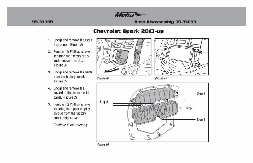
1. Unclipandremovetheradiotrimpanel.(FigureA)
2. Remove(4)Phillipsscrewssecuringthefactoryradioandremovefromdash.(FigureB)
3. Unclipandremovetheventsfromthefactorypanel.(FigureC)
4. Unclipandremovethehazardbuttonfromthetrimpanel.(FigureC)
5. Remove(5)Phillipsscrewssecuringtheupperdisplayshroudfromthefactorypanel.(FigureC)
Continue to kit assembly
(Figure A) (Figure B)
Chevrolet Spark 2013-up
(Figure B)
Step 3
Step 5
Step 4
Step 5
Kit Assembly 99-3309B
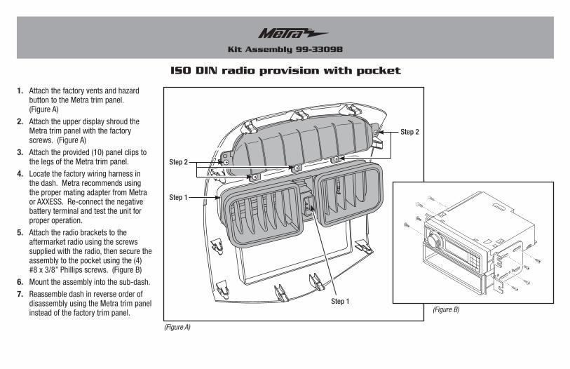
ISO DIN radio provision with pocket
1. AttachthefactoryventsandhazardbuttontotheMetratrimpanel.(FigureA)
2. AttachtheupperdisplayshroudtheMetratrimpanelwiththefactoryscrews.(FigureA)
3. Attachtheprovided(10)panelclipstothelegsoftheMetratrimpanel.
4. Locatethefactorywiringharnessinthedash.MetrarecommendsusingthepropermatingadapterfromMetraorAXXESS.Re-connectthenegativebatteryterminalandtesttheunitforproperoperation.
5. Attachtheradiobracketstotheaftermarketradiousingthescrewssuppliedwiththeradio,thensecuretheassemblytothepocketusingthe(4)#8x3/8”Phillipsscrews.(FigureB)
6. Mounttheassemblyintothesub-dash.
7. ReassembledashinreverseorderofdisassemblyusingtheMetratrimpanelinsteadofthefactorytrimpanel. (Figure B)
(Figure A)
Step 2
Step 1
Step 1
Step 2
Kit Assembly 99-3309B
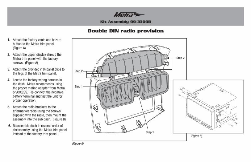
Double DIN radio provision
1. AttachthefactoryventsandhazardbuttontotheMetratrimpanel.(FigureA)
2. AttachtheupperdisplayshroudtheMetratrimpanelwiththefactoryscrews.(FigureA)
3. Attachtheprovided(10)panelclipstothelegsoftheMetratrimpanel.
4. Locatethefactorywiringharnessinthedash.MetrarecommendsusingthepropermatingadapterfromMetraorAXXESS.Re-connectthenegativebatteryterminalandtesttheunitforproperoperation.
5. Attachtheradiobracketstotheaftermarketradiousingthescrewssuppliedwiththeradio,thenmounttheassemblyintothesubdash.(FigureB)
6. ReassembledashinreverseorderofdisassemblyusingtheMetratrimpanelinsteadofthefactorytrimpanel. (Figure B)
(Figure A)
Step 2
Step 1
Step 1
Step 2

99-3309B
Axxess InterfaceInstallation
From the 16-pin harness:
• ConnecttheRedwirestotheignition/accessorywireoftheaftermarketradio.
• ConnecttheOrange/Whitewiretotheilluminationwireoftheaftermarketradio.Iftheaftermarketradiohasnoilluminationwire,tapeofftheOrange/Whitewire.
• ConnecttheBlue/Whitewiretotheampturnonwireoftheaftermarketradio.
• ConnecttheBrownwiretothemutewireoftheaftermarketradio.IftheaftermarketradiodoesnothaveaMutewire,tapeuptheBrownwire.
• ConnecttheWhitewiretotheleftfrontpositivespeakeroutputoftheaftermarketradio.
• ConnecttheWhite/Blackwiretotheleftfrontnegativespeakeroutputoftheaftermarketradio.
• ConnecttheGraywiretotherightfrontpositivespeakeroutputoftheaftermarketradio.
• ConnecttheGray/Blackwiretotherightfrontnegativespeakeroutputoftheaftermarketradio.
• TheVioletwireisnotusedintheapplication.
• TheViolet/Blackwireisnotusedintheapplication.
• TheGreenwireisnotusedintheapplication.
• TheGreen/Blackwireisnotusedinthisapplication.
Thefollowingwiresarefortheaftermarketradiosthathavenavigationbuiltin:
• ConnecttheLight Greenwiretotheparkingbrakewireoftheaftermarketnavigationradio.
• ConnecttheBlue/PinkwiretotheVSSorspeedsensewireoftheaftermarketnavigationradio.
• ConnecttheGreen/Purplewiretothereversewireoftheaftermarketnavigationradio.
From the 44-way harness:
• ConnecttheBlackwiretothegroundwireoftheaftermarketradio.
• ConnecttheRCA’stotheAUXinontheaftermarketradio(ifequipped).
Note: This will allow you to retain the 3.5 AUX JACKin the console.
• ConnecttheYellowwiretothe12-voltconstantwireoftheaftermarketradio.
• Ifthevehicleisamplifieddisconnectthe4-pinharnesslocatedbetweenthe44-wayand22-wayconnectorandconnectthesupplied4-pinto4-pinresistorpad.
•Cuttingtool•Crimpingtool•Tape•Connectors(butt-connectors,bellcaps,etc.)
TOOLS REQUIRED
•4-pinto4-pinresistorpadharness•16-pinwithstrippedleads•22-pinto44-pinCamaroHarness
•18-pinto10-pinHVACHarness
INTERFACE COMPONENTS
FEATURES
• Providesaccessory(12-volt10-amp)• RetainsR.A.P.(RetainedAccessoryPower)• Usedinamplifiedornon-amplifiedsystems• Retainsallwarningchimes• ProvidesNAVoutputs(parkingbrake,reverse,
mute,andV.S.S.)• RetainsOnStar/OEBluetooth• AdjustablevolumeforchimesandOnStar• Highlevelspeakerinput• Micro“B”USBupdatable• Retainsbalanceandfade
Installing the interface

99-3309B
Installing the interface
Amplified vehicles:
• ConnecttheVioletwiretotherightrearpositivewireoftheaftermarketradio.
• ConnecttheViolet/Blackwiretotherightrearnegativewireoftheaftermarketradio.
• ConnecttheGreenwiretotheleftrearpositivewireoftheaftermarketradio.
• ConnecttheGreen/Blackwiretotheleftrearnegativewireoftheaftermarketradio.
Non-amplified vehicles:
• CuttheresistorsfromtheGreen, Green/black, Purple, Purple/Blackrightbelowtheheatshrink.
• ConnecttheVioletwiretotherightrearpositivewireoftheaftermarketradio.
• ConnecttheViolet/Blackwiretotherightrearnegativewireoftheaftermarketradio.
• ConnecttheGreenwiretotheleftrearpositivewireoftheaftermarketradio.
• ConnecttheGreen/Blackwiretotheleftrearnegativewireoftheaftermarketradio.
• ThePinkwireisnotusedinthisapplication.
Installing the interface:
1. Withalltheconnectionscompleted,plugthe16and22pinharnessesintotheinterface.
2. Plugthe44pinGMharnessintothevehiclesideharness,andplugtheaftermarketradioharnessintotheaftermarketradio.
3. Reconnectthenegativebatteryterminal.
Initializing the interface
Attention: If the interface loses power for any reason, the following steps will need to be performed again.
• Initializetheinterfacebyturningtheignitiononfor30seconds,thenturntheignitionbackoff,thenbackonagain.
Note: If using the ASWC-1, connect it afteryou initialize the interface, with the key in theoff position.
Chime volume adjustment
1) Withcaron,shutoffcarandleavekeysinignition.Openthecardoorandleaveitopen.Chimeswillbeheard.
2) Wait10seconds,thenwithasmallscrewdriveradjustthepotentiometerfullycounterclockwise(allthewayleft),thenclockwisetoraisechimelevelandcounterclockwisetolowerthechimelevel.
3) Whenthevolumeisatthedesiredlevel,removethekeysfromtheignition.Thiswilllockthechimevolumeatitscurrentlevel.
Audio level adjustment
1) Startyourvehicleandturnontheradiohavingaudioplaying.
2) Turnyouraftermarketradio’svolumeup¾oftheway.
3) Withasmallscrewdriveradjustthepotentiometerclockwisetoraisetheaudiolevelandcounterclockwisetolowertheaudiolevel.
4) Onceatdesiredlevelyouraudioadjustmentiscomplete.

99-3309B
The OEM radio is used to customize certain features of the vehicle.
UsetheoptionalLCDtoadjustthesefeaturesaccordingly:
1. PressESC,andthenpressENT:“SetLanguage”willappearonthescreen.
2. Tochangethelanguage,pressENT,andthenpressthearrowupanddownbuttonstochangethelanguage.
3. Onceyouhaveselectedyourlanguage,press ESC togobacktothemainscreen.
4. Ifyoudonotwishtochangethelanguage,youcanscrollupanddownthroughthedifferentsettingswiththearrowupanddownbuttons.
Note: What these options are depends on the vehicle/trim-level it isinstalled into.
5. Remembertopress ENTtochangethedesiredsetting.
Vehicle customizationwith optional LCD
(AXXESSpart#XIA-LCDsoldseparately)
OnStar level adjustment
ToadjusttheOnStarvolumelevelfindtheBlack/Yellowwireonthe16-pinharness.PushtheblueOnStarbutton,whilethevoiceisspeakingtapthe Black/Yellowwiretoground.OncethevolumeissetitwillstayatthatvolumeuntiltheBlack/Yellowwireistappedtogroundagain.Thiscanbesetduringinstallationandthenleftalone.Ifuseradjustmentisdesired,thecustomermayalsotap“VolumeUp”ordownonthesteeringwheel(ifequipped)toadjusttheOnStarlevel.
Additional 12-pin harness (ASWC-1)
• This12-pinharnessistobeusedinconjunctionwiththeASWC-1(notincluded).PleaserefertotheASWC-1instructionsforprogramming.