applications of spark plasma sintering - mephilemc-lab.mephi.ru/content/file/news/goto.pdf ·...
TRANSCRIPT

1
Applications of Spark Plasma Sintering
Takashi Gotof l h h k
IMR, Tohoku University
Institute for Materials Research, Tohoku University, Japan
2nd International school-seminar “Perspective technology of materials consolidation with electromagnetic fields”
1st Russia-Japan SPS WorkshopMoscow, Russia, May 2022, 2013
Outline
Introduction
Spark Plasma Sintering (SPS)
Transparent Lu-based Oxide Ceramics by SPS
Lu2O3, Lu3Al5O12 (LuAG) , Lu2Ti2O7, Lu3NbO7, Lu2Hf2O7
Non-Oxide High-Temperature Ceramic Composite by SPS
Carbide-Boride Eutectic Composite (SiC-ZrB2)
Covalent Bond Ceramic Composite by SPS
cBN Based Composites cBN-Based Composites
Summary

2
SPS Forum of Japan
1990 SPS Started in Japan
1992 First SPS in IMR
1996 Forum in IMR
KEY(spark plasma sintering)
by Scopus
2000 Forum in IMR
2006 New SPS in IMR
2009 Forum in IMR
2012 17th Forum in IMR
Papers of SPS
2016.5.15
Spark Plasma Sintering
3
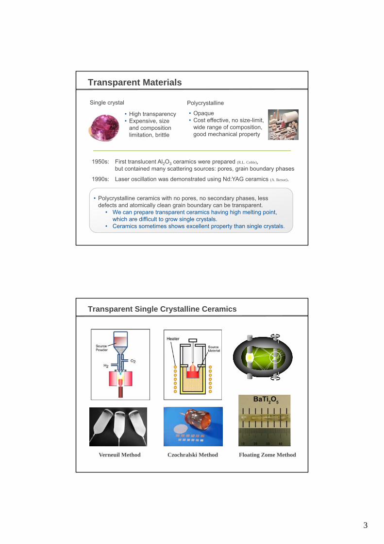
Transparent Materials
PolycrystallineSingle crystal
• High transparency• Expensive, size
and composition
• Opaque• Cost effective, no size-limit,
wide range of composition,
1950s: First translucent Al2O3 ceramics were prepared (R.L. Coble),but contained many scattering sources: pores, grain boundary phases
1990s: Laser oscillation was demonstrated using Nd:YAG ceramics (A. Ikesue).
and composition limitation, brittle
g p ,good mechanical property
• Polycrystalline ceramics with no pores, no secondary phases, less defects and atomically clean grain boundary can be transparent.
• We can prepare transparent ceramics having high melting point, which are difficult to grow single crystals.
• Ceramics sometimes shows excellent property than single crystals.
Transparent Single Crystalline Ceramics
Verneuil Method Czochralski Method Floating Zome Method

4
Spark Plasma Sintering (SPS)
Strategy Easy way
Cost-effective
Short time
Characteristics:
Short-time
Low-temperature
Common commercial powder source
SPS and Post-annealingCharacteristics:
Consolidation in a short timeand at a relatively low sintering temperature
Precise pressure control
High speed cooling
Transparent ceramics
Sintering Mechanism
Cu Ni
・Ist Stage(Density<65%)Neck growth and re-aggangement of particle
・2nd Stage (Density= 65~92%)Continuous pore channelSpherical to polygonal pores
・3rd Stage (Density>92%)Diffusion and disappear of pores through grain-boundary
5
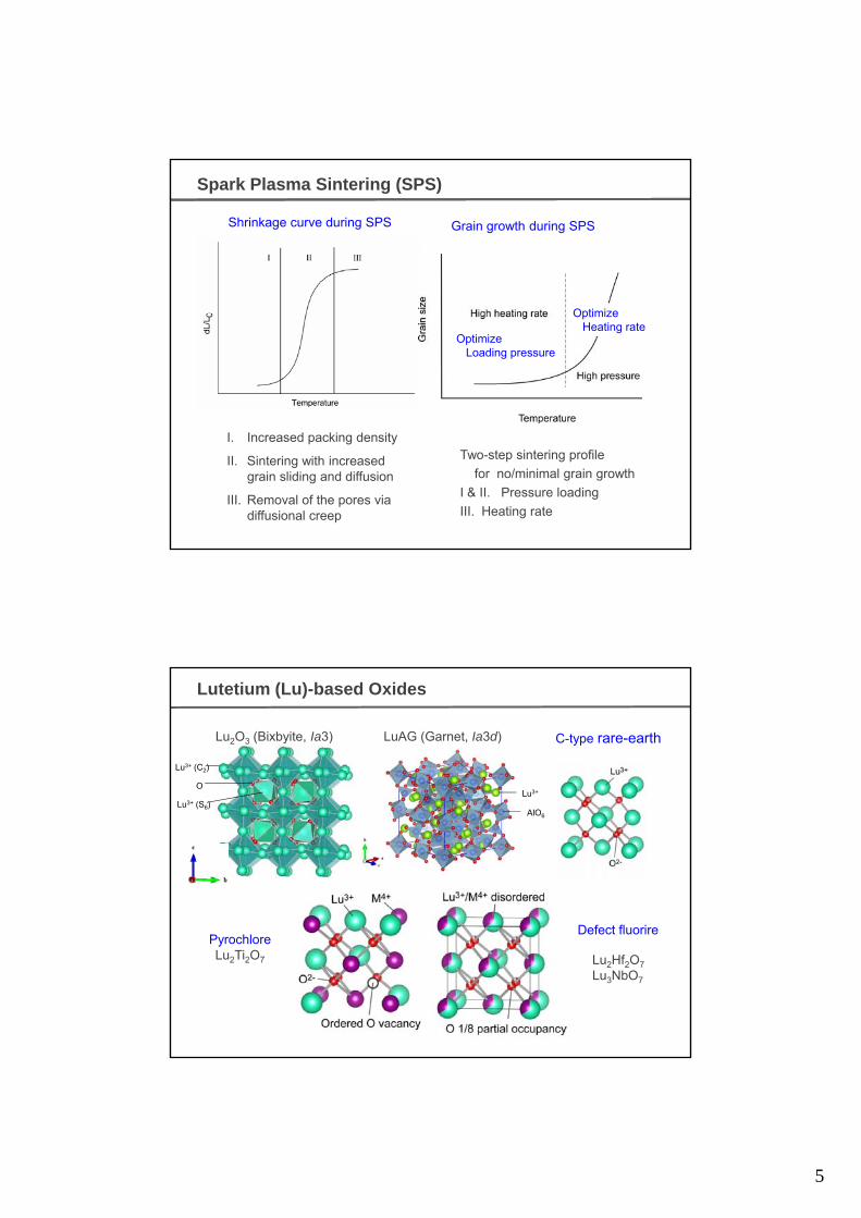
Spark Plasma Sintering (SPS)
Shrinkage curve during SPS Grain growth during SPS
Optimize Loading pressure
Optimize Heating rate
I. Increased packing density
II. Sintering with increased grain sliding and diffusion
III. Removal of the pores via diffusional creep
Two-step sintering profile
for no/minimal grain growth
I & II. Pressure loading
III. Heating rate
Lu3+ (C2)
O
Lutetium (Lu)-based Oxides
Lu3+
LuAG (Garnet, Ia3d)Lu2O3 (Bixbyite, Ia3) C-type rare-earth
Lu3+ (S6)AlO6
Defect fl orirePyrochloreLu2Ti2O7 Lu2Hf2O7
Lu3NbO7
Defect fluorire

6
Lutetium (Lu)-based Oxides
Practical transparent Lu-based oxide
Lu2O3(Hot pressing + Hot isostatic pressing)
Lu3Al5O12 (LuAG)(Vacuum sintering)
J. Sanghera, et al., Opt. Mater., 33, 670-4 (2011). Y. Shi, et al., J. Appl. Phys., 109, 013522 (2011).
Main issues: High sintering temperature and large grains
10%Yb Pr
There is no report on Lu2O3 and LuAG prepared by SPS.
New Lu-based oxides
There is no report on optical property of Lu-basedoxide single crystal and sintered body.
Main issues: High sintering temperature and large grains
Introduction - Lu2O3
Previous study on transparent Lu2O3 ceramic
SampleSynthesis method
Sintering conditions
Grain sizeTransmittance at 550 nm (Thickness)
Reference
5 at%VS 1973 K f 5 h
In nano Not given E. Zych, J. Alloy. Compd.,
Transparent Lu O ceramics have been prepared by conventional
5 at% Eu:Lu2O3
VS 1973 K for 5 hIn nano range
Not given (translucent)
E. Zych, J. Alloy. Compd., 34, 391-4 (2002).
5 at% Eu:Lu2O3
NPS(H2) 2123 K for 6 h 50–60 m 80% (1 mm)Q.W. Chen, J. Am. Ceram. Soc., 89, 2038-42 (2006).
3 at% Nd:Lu2O3
NPS(H2) 2153 K for 8 h ~50 m64% (1.4 mm)
50% for Lu2O3
D. Zhou, J. Am. Ceram. Soc., 92, 2182-7 (2009)
VS: vacuum sintering, NPS(H2): pressureless sintering in H2
Transparent Lu2O3 ceramics have been prepared by conventionalsintering techniques.
The main issues are high sintering temperature (over 1973 K), longsintering time (> 5 h) and large grains (> 50 m).
There is no report on preparation of Lu2O3 by SPS.
7
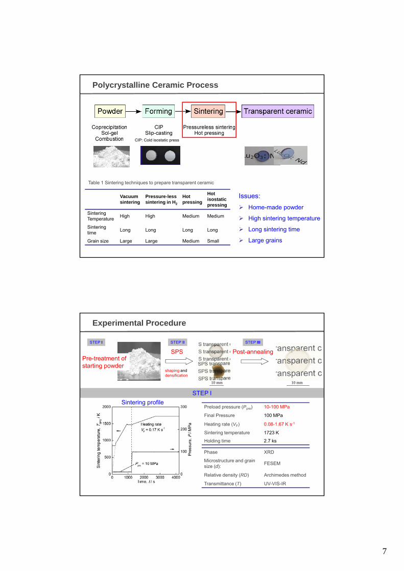
Polycrystalline Ceramic Process
Vacuum Pressure-less HotHot Issues:
CIP: Cold isostatic press
Table 1 Sintering techniques to prepare transparent ceramic
Vacuum sintering
Pressure-less sintering in H2
Hot pressing
isostatic pressing
SinteringTemperature
High High Medium Medium
Sintering time
Long Long Long Long
Grain size Large Large Medium Small
Issues:
Home-made powder
High sintering temperature
Long sintering time
Large grains
Experimental Procedure
SPS
shaping and
Post-annealingPre-treatment of starting powder
STEP II STEP IIISTEP I
STEP I
densification
10 mm 10 mm
Preload pressure (Ppre) 10-100 MPa
Final Pressure 100 MPa
Heating rate (VF) 0.08-1.67 K s-1
Sintering temperature 1723 K
Sintering profile
Phase XRD
Microstructure and grain size (d):
FESEM
Relative density (RD) Archimedes method
Transmittance (T) UV-VIS-IR
g p
Holding time 2.7 ks

8
Sintering Curves of Lu2O3 at Different Ppre and VF
VF = 0.17 K s-1 Ppre = 10 MPa
Relative density increased significantly at the point where final pressure was applied under low Ppre.
Relative density increased significantly at a high heating rate.
Journal of the European Ceramic Society,31(2011) 1597. An, Ito, Goto
Effect of Ppre on Microstructure of Lu2O3 at VF= 0.17 Ks-1
Ppre=10 MPa Ppre=100 MPa
Grain size decreased with increasing final pressure.
9
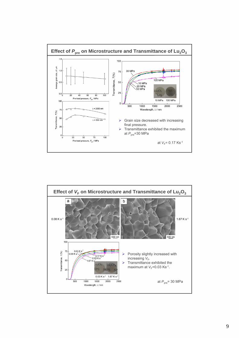
Effect of Ppre on Microstructure and Transmittance of Lu2O3
10 MPa 100 MPa
at VF= 0.17 Ks-1
Grain size decreased with increasing final pressure.
Transmittance exhibited the maximum at Ppre=30 MPa
Effect of VF on Microstructure and Transmittance of Lu2O3
1.67 K s-10.08 K s-1
Porosity slightly increased with i i V
0.03 K s-1 1.67 K s-1
increasing VF. Transmittance exhibited the
maximum at VF=0.03 Ks-1.
at Ppre= 30 MPa

10
Effect of annealing on Transmittance of Lu2O3
TAN
Annealing can improve the transparency.
The optimal annealing temperature was 1323 K.
Comparison on Transparency and Grain Size of Lu2O3
SampleSynthesis method
Sintering conditions
Grain sizeTransmittance at 550 nm(Thickness)
Reference
5 at.%Eu:Lu2O3
VS 1973 K for 5 h In nano range Not given (translucent)
E. Zych, J. Alloy. Compd., 34, 391-4 (2002).
0 15 at % about 1973 K for Not given (near J Lu Appl Phys Lett 810.15 at. % Nd:Lu2O3
VS about 1973 K for 5 h Not given Not given (near
theoretical value)J. Lu, Appl. Phys. Lett., 81, 4324-6 (2002).
5 at.% Eu:Lu2O3
NPS(H2) 2123 K for 6 h 50–60 m 80% (1 mm) Q.W. Chen, J. Am. Ceram. Soc., 89, 2038-42 (2006).
3 at.% Nd:Lu2O3
NPS(H2) 2153 K for 8 h ~50 m64% (1.4 mm)50% for Lu2O3
D. Zhou, J. Am. Ceram. Soc., 92, 2182-7 (2009)
5 at.% Eu:Lu2O3
VS+ HIP1873-1923 K for 2h 2123 K, 200 MPa for 4 h
>10 mNot given (high)(1.6-1.7 mm)
Z.M. Seeley, Opt. Mater., 33, 1721-6 (2011).
10 at.% HP +HIP1873 K for 2h 1873 K 200 20 50 80% (3 ) J. Sanghera, Opt. mater., 33,10 at.%
Yb:Lu2O3 HP +HIP 1873 K, 200
MPa for 2 h20–50 m ~80% (3 mm) J. Sanghera, Opt. mater., 33,
670-4 (2011).
5 at.% Yb:Lu2O3
NPS(H2) 1953 K for 45 h Not given 48% (1 mm) H,J. Zhang, Opt, Mater., in press.
Lu2O3 SPS 1723 K, 100 MPa for 2.7 ks 0.91 m 71.4 % (1 mm) This work
VS: vacuum sintering, HP: hot pressing, NPS(H2): pressureless sintering in H2, HIP: hot isostatic pressing
Nd:Lu2O3 by SPS first laser material by SPS

11
Transmittance of LuAG after Annealing
Calculated value
Transparent LuAG was obtained at arelative low sintering temperature of1723 K.
TAN = 1423 K
Effect of TSPS on Microstructure and Transmittance of Lu2Ti2O7
TAN = 1023 K
1373 K 1523 K
Arrows refer to pores. Reactive sintering
1573 K 1623 K
The transmittance was 57 and 74% at a wavelength of 550 and 2000 nm, respectively.
1723 K 1823 K
The calculated value from the refractive index
Journal of the American Ceramic Society, 94(2011) 3851. An, Ito, Goto

12
Effect of TSPS on Transmittance of Lu3NbO7
Reactive sintering
Tsps: (a) 1573 K, (b) 1673 K, (c) 1723 K,
(d) 1773 K, (e) 1823 K
※ Annealed at 1123 K in air for 6 h
Transmittance increased with increasing Tsps from 1573 (a) to 1773 K (d).
It became opaque at Tsps 1823 K (e).
※ Annealed at 1123 K in air for 6 h
Effect of Annealing on Transmittance of Lu3NbO7
TSPS : 1723 K
Annealing at (6h in air):
(a) 1023 K, (b) 1123 K, (c) 1223 K,
(d) 1323 K (e) 1423 K (f) 1523 K
The rim part became transparent at 1023 K (a).
The whole part became transparent at 1123-1323 K (b-c) .
It became opaque at 1423 K .
(d) 1323 K, (e) 1423 K, (f) 1523 K
13
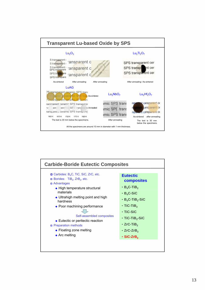
Transparent Lu-based Oxide by SPS
Lu2O3 Lu2Ti2O7
As-sintered After annealing
LuAG
Lu3NbO7 Lu2Hf2O7
As-sintered
After annealing / As-sinteredAfter annealing
s s e ed
The text is 30 mm below the specimens. After annealing
As-sintered after annealing
The text is 30 mmbelow the specimens.
All the specimens are around 10 mm in diameter with 1 mm thickness.
Carbide-Boride Eutectic Composites
Carbides: B4C, TiC, SiC, ZrC, etc.
Borides: TiB2, ZrB2, etc.
Advantages
◆ High temperature structural
Eutectic composites
• B4C-TiB2g pmaterials
◆ Ultrahigh melting point and high hardness
◆ Poor machining performance
Self-assembled composites
◆ Eutectic or peritectic reaction
• B4C-SiC
• B4C-TiB2-SiC
• TiC-TiB2
• TiC-SiC
• TiC-TiB2-SiC◆ Eutectic or peritectic reaction
Preparation methods
◆ Floating zone melting
◆ Arc melting
• ZrC-TiB2
• ZrC-ZrB2
• SiC-ZrB2
14
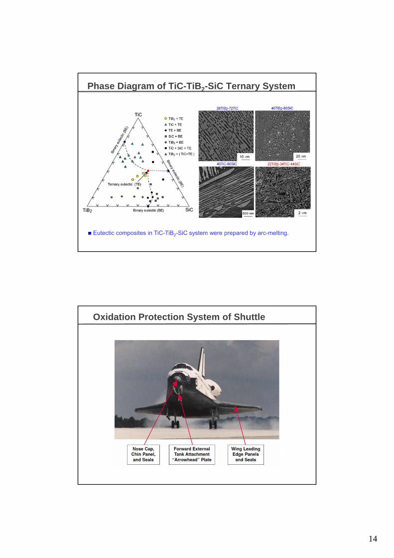
Phase Diagram of TiC-TiB2-SiC Ternary System
Eutectic composites in TiC-TiB2-SiC system were prepared by arc-melting.
Oxidation Protection System of Shuttle
15
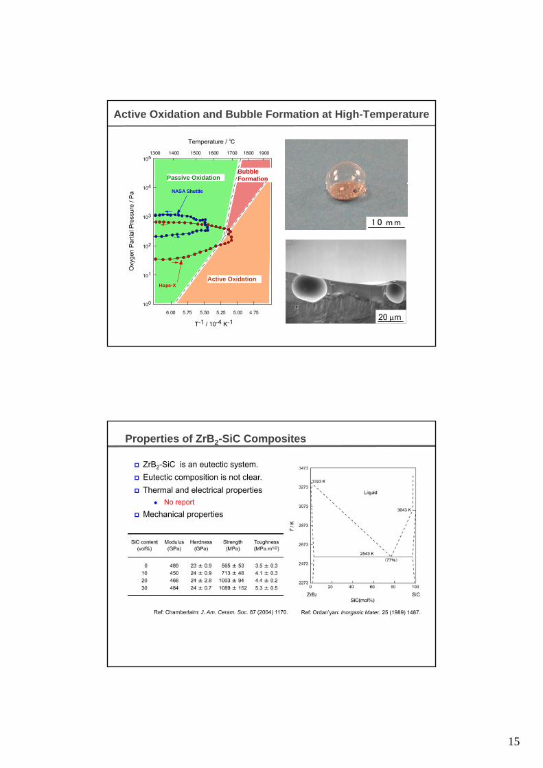
Active Oxidation and Bubble Formation at High-Temperature
1900180017001600150014001300
Temperature / ℃
105
Passive OxidationBubble Formation
102
103
104
xyg
en P
artia
l Pre
ssur
e / P
a NASA Shuttle
1 0 m m
4.755.005.255.505.756.00
T-1 / 10-4 K-1
101
100
Ox
Hope-XActive Oxidation
20 m
Properties of ZrB2-SiC Composites
ZrB2-SiC is an eutectic system.
Eutectic composition is not clear.
Thermal and electrical properties
No report No report
Mechanical properties
Ref: Chamberlaim: J. Am. Ceram. Soc. 87 (2004) 1170. Ref: Ordan’yan: Inorganic Mater. 25 (1989) 1487.

16
Microstructure of ZrB2-SiC Composites
80ZrB2-20SiC(mol%) 60ZrB2-40SiC
ZrB2ZrB2
ZrB2-SiC composites
Z B
40ZrB2-60SiC 20ZrB2-80SiC
2 ZrB2: gray
SiC: black
40ZrB2-60SiC(mol%)
Uniform microstructure
SiC
Sintering of ZrB2-SiC Composites During SPS
0-80 mass% SiC, 2273 K, 180 s
Shrinkage completion temperature increased with increasing SiC content.
Shrinkage of 80 mass% SiC started at 2113 K and displacement continued after holding at 2273 K.
Shrinkage of composites containing 20-60 mass% SiC completed within 60 s at 2273 K.
Addition of SiC up to 80 mass% improved densification of ZrB2.
17
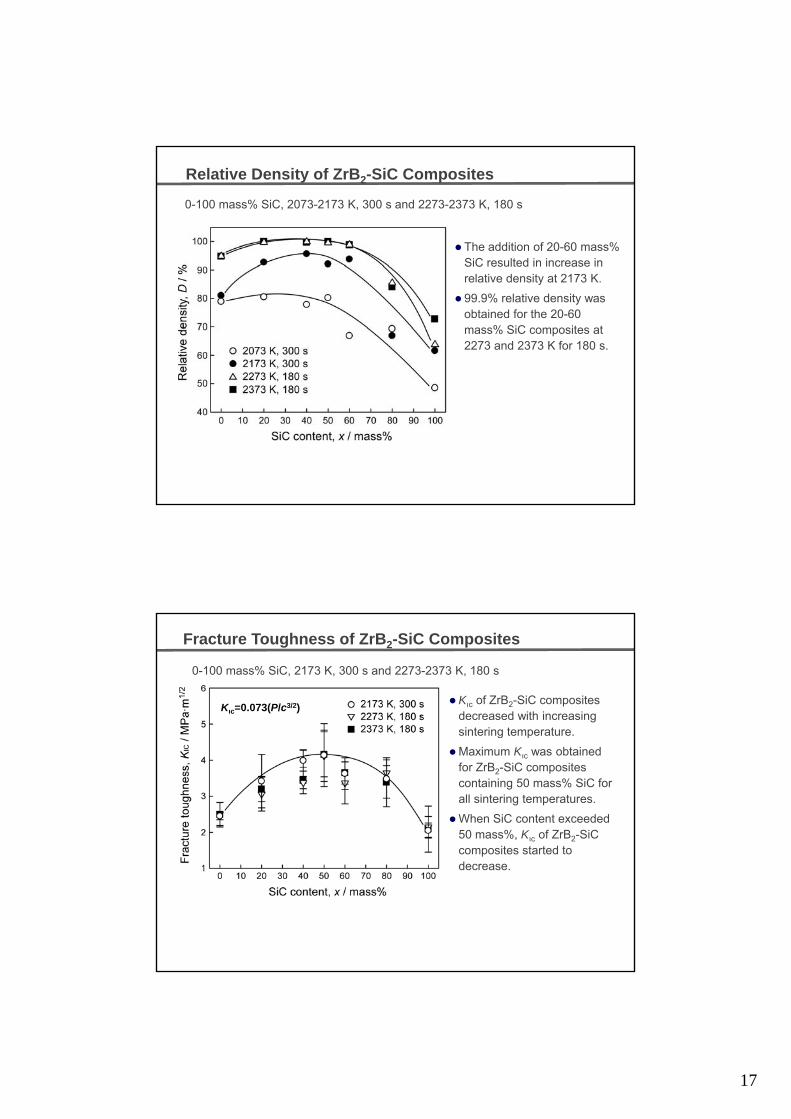
Relative Density of ZrB2-SiC Composites
0-100 mass% SiC, 2073-2173 K, 300 s and 2273-2373 K, 180 s
The addition of 20-60 mass% SiC resulted in increase inSiC resulted in increase in relative density at 2173 K.
99.9% relative density was obtained for the 20-60mass% SiC composites at 2273 and 2373 K for 180 s.
Fracture Toughness of ZrB2-SiC Composites
Kıc of ZrB2-SiC composites decreased with increasing sintering temperature
0-100 mass% SiC, 2173 K, 300 s and 2273-2373 K, 180 s
Kıc=0.073(P/c3/2)
sintering temperature.
Maximum Kıc was obtained for ZrB2-SiC composites containing 50 mass% SiC for all sintering temperatures.
When SiC content exceeded 50 mass%, Kıc of ZrB2-SiC composites started tocomposites started to decrease.

18
Microstructure of ZrB2-SiC Composites
40 mass% SiC, 2173 K-300 s, 2373 K-180 s
2173 K 2273 K
At 2173 and 2273 K, microstructures comprise equiaxed ZrB2 and α-SiCgrains.
2373 K2313 K
Elongated α-SiC grains formed at 2313 K and irregular texture composed of ZrB2 and fine α-SiCgrains were observed at 2373 K.
Melting Point of ZrB2-SiC Eutectic Composites
Spark plasma sintering◆ Heating to be melted
Melting point: 2570 K
Eutectic composition:◆ 41.5ZrB2-58.5SiC (mol%)
Eutectic melting point:◆ 2570 K
19
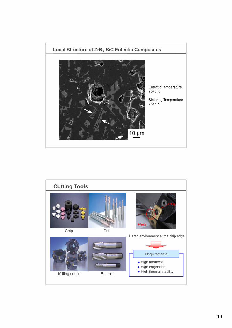
Local Structure of ZrB2-SiC Eutectic Composites
Eutectic Temperature2570 K
Sintering Temperature2373 K
Cutting Tools
Chip
Chip Drill
Work
Harsh environment at the chip edge
Milling cutter Endmill
Requirements
High thermal stability
High hardness
High toughness

20
Cubic Boron Nitride(cBN)
cBN
Non-sinterability
Transformation to hBN at high temperature
hBN
Ultra-high pressure (>5GPa) sintering of cBN or hBN
Fabrication of cBN Cutting Tools
g p ( ) g
with binders such as metal Al and TiC
Moderate pressure (<100 MPa) hot- pressing
M ti l li tiMore practical applications

21
Microstructure of Al2O3-cBN Composite
1573K 1673K
20vol%cBN, 1573-1873K, 600s
Sharp edged well adhered cBN particles at 1573K
1873K1773K
1m1m
1573K
A small amount of voids and cracks around cBN particles at 1673K
Phase transformation of cBN to hBN at 1773-
1m1m
of cBN to hBN at 1773-1873K
XRD Profiles of Al2O3-cBN Composites
20vol%cBN, 1573-1873K, 600s 0-50vol%cBN, 1473-1673K, 600s
1573K
1473K1573K1673K
1873K
1773K
1673K
A slight transformation to hBN at 1673K.
Density of more than 98% at 1573-1673K (10-20vol%cBN)
1873K

22
Vickers Hardness of Al2O3-cBN Composite
0-30vol%cBN, 1473-1873K, 600s
20vol%cBN, 1573K
The highest hardness of 26GPa at 1573K (20vol% cBN)
Hv = 26 GPa1473 1457 1673 1773 1873
K
Strategy to Consolidate cBN Powder
Modification of Powder Surface (Coating)
◆Fluidized bed CVD (FBCVD)
Rotary CVD
Nano-particle/Nano-film Coating on Powders
◆Ni, SiO2 Coating on cBN Powder
Consolidation of cBN-base Composites by SPSConsolidation of cBN-base Composites by SPS
23
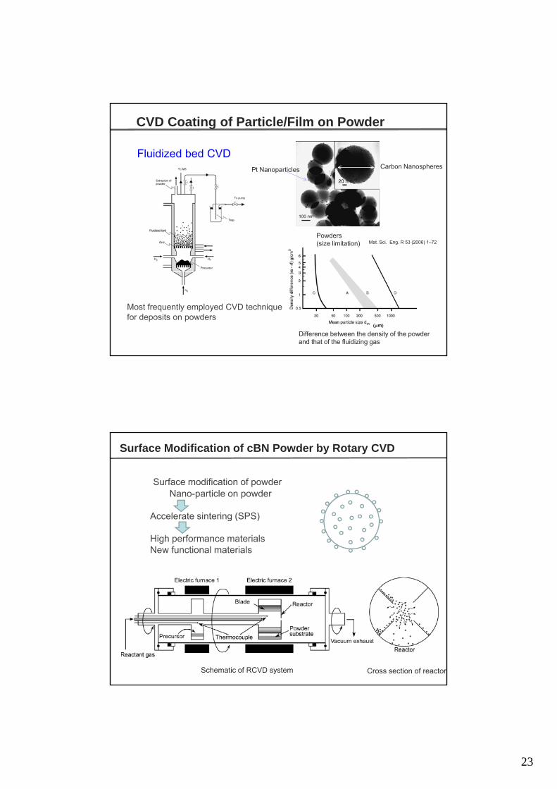
Carbon NanospheresPt Nanoparticles
CVD Coating of Particle/Film on Powder
Fluidized bed CVD
Powders(size limitation) Mat. Sci. Eng. R 53 (2006) 1–72
Difference between the density of the powder and that of the fluidizing gas
Most frequently employed CVD technique for deposits on powders
m
Surface Modification of cBN Powder by Rotary CVD
Surface modification of powderNano-particle on powder
Accelerate sintering (SPS)Accelerate sintering (SPS)
High performance materialsNew functional materials
Schematic of RCVD system Cross section of reactor
24
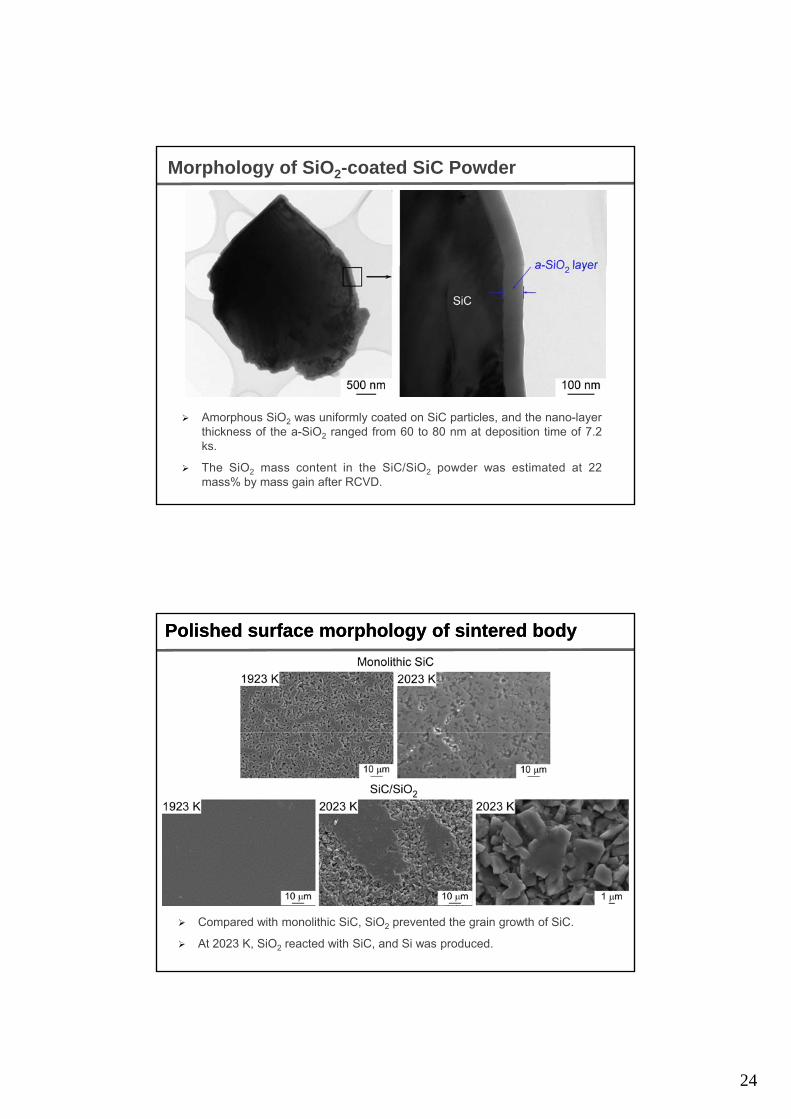
Morphology of SiO2-coated SiC Powder
Amorphous SiO2 was uniformly coated on SiC particles, and the nano-layerthickness of the a-SiO2 ranged from 60 to 80 nm at deposition time of 7.2ks.
The SiO2 mass content in the SiC/SiO2 powder was estimated at 22mass% by mass gain after RCVD.
Polished surface morphology of sintered bodyPolished surface morphology of sintered body
Compared with monolithic SiC, SiO2 prevented the grain growth of SiC.
At 2023 K, SiO2 reacted with SiC, and Si was produced.
25
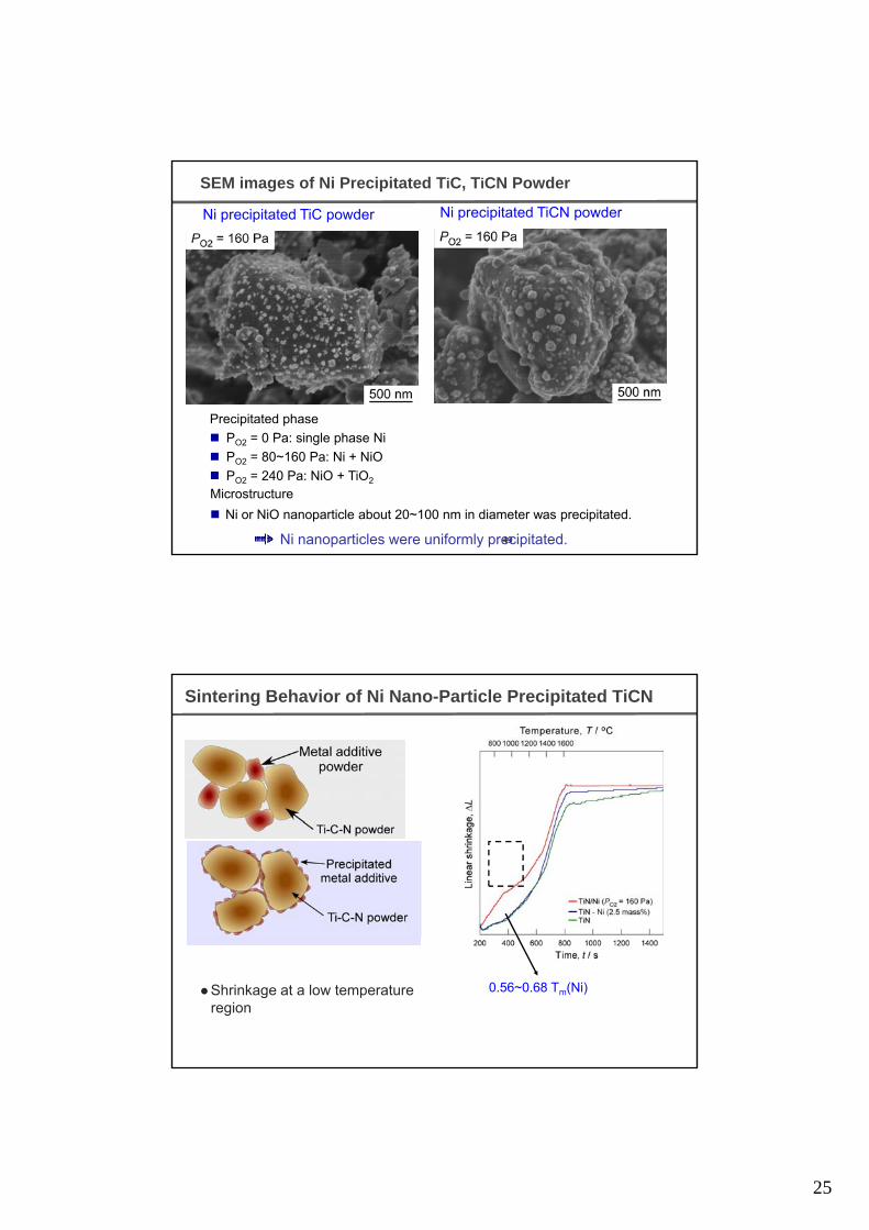
SEM images of Ni Precipitated TiC, TiCN Powder
Ni precipitated TiCN powderNi precipitated TiC powder
Precipitated phase
49
p p
PO2 = 0 Pa: single phase Ni
PO2 = 80~160 Pa: Ni + NiO
PO2 = 240 Pa: NiO + TiO2
Microstructure
Ni or NiO nanoparticle about 20~100 nm in diameter was precipitated.
Ni nanoparticles were uniformly precipitated.
Sintering Behavior of Ni Nano-Particle Precipitated TiCN
Shrinkage at a low temperature region
0.56~0.68 Tm(Ni)
26
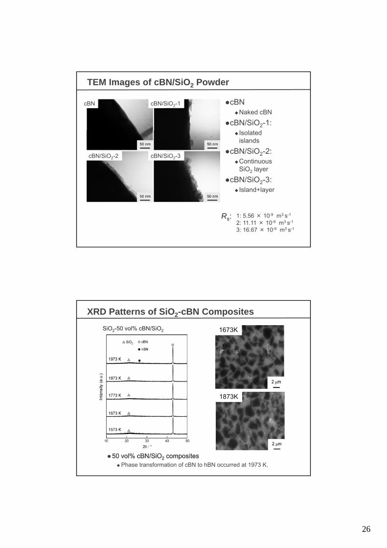
TEM Images of cBN/SiO2 Powder
cBN◆Naked cBN
cBN/SiO2-1:
cBN cBN/SiO2-1
◆ Isolatedislands
cBN/SiO2-2:◆Continuous
SiO2 layer
cBN/SiO2-3:◆ Island+layer
cBN/SiO2-2 cBN/SiO2-3
◆ Island+layer
1: 5.56 × 10⁻⁹ m3 s-1
2: 11.11 × 10⁻⁹ m3 s-1
3: 16.67 × 10⁻⁹ m3 s-1
Rs:
XRD Patterns of SiO2-cBN Composites
SiO2-50 vol% cBN/SiO2 1673K
1873K
5050 volvol%% cBN/SiOcBN/SiO22 compositescomposites◆ Phase transformation of cBN to hBN occurred at 1973 K.
27
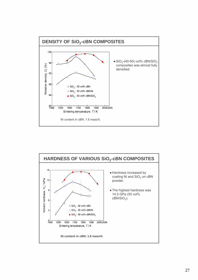
DENSITY OF SiO2-cBN COMPOSITES
SiO2-(40-50) vol% cBN/SiO2
composites was almost fully p ydensified.
Ni content in cBN: 1.6 mass%
HARDNESS OF VARIOUS SiO2-cBN COMPOSITES
Hardness increased by coating Ni and SiO2 on cBN powder.
The highest hardness was 14.5 GPa (50 vol% cBN/SiO2).
Ni content in cBN: 1.6 mass%
28
Summary SPS (Spark Plasma Sintering)
Spark? Plasma? Unknown
ECAS (Electric Current Activated/Assisted Sintering)
M T t b El t i Fil d? U kMass Transport by Electric Filed? Unknown
Effects of SPSNon-Sinterable Refractory Material, Easy-to-decompose Materials
in a short time (within a few minutes)
Meta-stable or Non-stable Materials are sinterable.
Excess surface energy (Stress on the surface, Defects…)Excess surface energy (Stress on the surface, Defects…)
Re-arrangement and desification before neck growth
Future Study Sintering Mechanism
Non-sinterable Material Surface Modification of Powder