application ofultrasonic rayleigh wave to testing ... · application ofultrasonic rayleigh wave to...
TRANSCRIPT
Structural Analysis of Historical Constructions - Modena, Lourenço & Roca (eds) © 2005 Taylor & Francis Group, London, ISBN 04 1536 379 9
Application ofultrasonic Rayleigh wave to testing ofmasonry materiaIs
M. Sklodowski Institute of Fundamental Technological Research Polish Academy of Sciences, Warszawa, Poland
ABSTRACT: The paper describes the use ofultrasonic edge transducers for testing the properties of masonry materiais, both fresh-made and weathered, and after the treatment with colloidal silica. The method proposed is completely non-destructive because no additional coupling material is used, and this is particularly important in the case oftesting historical structures where no damage or pore filling should be introduced. The paper presents principies of surface Rayleigh wave measurement by means of edge transducers, as well as basic theoretical considerations and the experimental setup. Finally, the results are given of laboratory testing of marbles and bricks as well as of in situ testing of brick masonry originating from a gothic church in Poland.
INTRODUCTION
Rayleigh wave was primarily used in stone testing for measurement of elastic constants of stones (Pininska 1986). This comes from the fact that elastic constants can be expressed by means of longitudinal, compressive and transversal, shear wave velocities.
Let us denote the measured velocities of shear and longitudinal waves as V s and VI respectively. Then the material constants called "dynamic material constants" can be expressed by the equations
where Vd is the Poisson 's ratio, Ed is the Young 's modulus and p is the material density.
The shear wave velocity can be evaluated via Rayleigh surface wave V R velocity measurements which can give a good approximation of the former according to formula Vs = VR/0.9, valid for typical values ofthe Poisson's ratio.
Generally, surface wave velocity measurements are made using industrial transducers in the frequency range of a few MHz. The measurements are taken mostly on metais, and they use the influence ofthe second criticai longitudinal wave incidence angle on the border between the polymethyl-metacrylate (PMMA) wedge and the tested material. Introducing the wave
395
with the PMMA wedge needs also some coupling media.
An interesting study of the Rayleigh wave propagation in Dionysos Marble in the Athens Acropolis Parthenon (Stavropoulou et aI. 2003) was done with transducers made of a mixture of tungsten particles embedded in epoxy resin. The authors report that transducers were not strong enough so unfortunately several pairs ofthem were had to be used for completing the research.
Rayleigh waves can also be generated in various materiais by means of solid state lasers built on Neodimium dopped Yttrium Aluminium Garnet crystals (Nd:YAG laser) using an ablation generation mechanism. This kind of technique can give a valuable insight into the material heterogeneity (Owino et aI. 1999) but equipment cost is very high and the portability is much lower than that of edge probes.
The edge probes (P~ski 1984) can introduce the surface wave in various kinds of materiais without any coupling. This is very important in the case of porous materiais where coupling media can get inside and thus significantly modify wave propagation conditions.
The described probes generate the Rayleigh wave which penetrates an outer skin layer of the tested material to the depth of a few millimeters only. Thus measured wave velocities and/or attenuations are not influenced by bulk material properties which makes the method suitable for a detection of changes of elastic properties ofthe surface ofmaterials. This property seems to be very suitable for evaluation of stone strengthening procedures based on impregnation of a material with colloidal silica.

Figure I. Schematic diagram of surface wave generation with edge probes.
Figure 2. Edge probes pressed against the surface of a stone specimen prepared for impregnation.
2 MEASUREMENT METHOD
2. 1 Wave generation
Piezo-transducers are glued to the surface of steel edges which guide the ultrasonic wave to the edge nibs (P~ski & Ranachowski 1988) which are pressed against the specimen surface as shown in Figure 1. Measurements are made using one transm itting and one or two receiving transducers spaced at known distances along a straight line on the surface of the specimen.
Up to present the edge probes for frequencies from 1 MHz to 4 MHz were constructed and used. The amount of energy delivered to the surface of materiaIs depends strongly on the surface conditions but pressing the probes with a force of approx. 10 N, as shown in Figure 2, usually solves the problem.
2.2 Wave velocity measurement
There is a high attenuation ofultrasonic waves in most building industry materiaIs like stones, rocks, concrete etc. for the frequency range used in the described experiments. As a result a short distance of a few
centimeters between transmitting and receiving transducers must be maintained, and hence a short measurement base should be used for ultrasonic wave velocity measurements (Sklodowski et aI. 2002). Fortunately enough, the short measurement base is an advantage in the case of detecting local anomalies in tested material. For greater distances, averaging the measurements along a full path can give the desired value together with variation ofthe measured velocity.
The developed experimental equipment consists of a portable computer, a defectoscope card and an oscilloscope card, put together with batteries into a metal case, with the edge probe being connected to the defectoscope card (Sklodowski et aI. 2003). Rated frequency of the probe is 1.25 MHz.
All elements of the equipment can be seen in Figure 4 which shows measurement of the surface wave propagation in brick masonry in a gothic church.
The equipment was calibrated prior to the experiments by measuring propagation time of the surface wave along two different distances between edge nibs. Calibration measurements were taken using a steel caliper, PMMA, glass and aluminum specimens to make sure that the calculated time delays of the probe and electronic devices are correct.
The propagation time ofthe surface wave was calculated using correlation procedure in the spectral domain ofthe recorded signals and a time shift between the wave recorded in calibration experiments and the wave measured was found.
3 EXPERlMENTS
3.1 In laboratory
Brick and marble materiais were chosen for experimental studies of surface wave propagation in both unimpregnated and impregnated specimens.
A brick was excavated during reconstruction works in a XIV century church but is actually not that old .
Marble materiais were of two types. One marble specimen was from Sweden and was exposed to natural weathering conditions during the period of one year (within TEAM Project ofEU 5th FP). Two other specimens were ofGoia Marble: one specimen was of fresh intact rock and the other specimen was exposed to one cycle of heating in 70°C. All four samples were tested under air-dry conditions, both before and after the impregnation.
An example of specimen preparation is shown in Figure 3.
Parallellines marking a contact position of the edge nibs ofthe probe were drawn with a pencil on the specimen surface. Then a plastic adhesive tape was used to define individual measurement cells of area of 2 cm2
each as well as to separate one cell from another. Then
396

Figure 3. Specimen of Goia Marble during impregnation. Amount of impregnant No 2 increases from right to left.
the measurement ofthe surface wave velocity was conducted for unimpregnated material. Subsequently each individual cell was saturated with impregnant, in several steps, if necessary, until the prescribed surface density of impregnating solution was reached.
In the case of Goia Marble shown in Figure 3 the densities used were 0.25, 0.5, 1.0 and 2.0 11m2 .
The next surface wave measurements were taken three and a half weeks after the impregnation procedure.
3.2 Colloidal silica impregnants
Three types of colloidal silica impregnants were used. Impregnant No. I was applied to the old brick. Impregnant No. 2 was used in treatment of the both Goia Marble specimens as well as for the naturaIly weathered marble. Impregnant No. 3 was used for the naturaIly weathered marble.
Impregnant No. 1 was a stone strengthener based on the silicic acid ethyl ester as an active ingredient.
This ingredient reacts with water stored in the stone pore system or with humidity of air. During this reaction, amorphous and hydrous silicon dioxide linked through soft segments is deposited as a binder.
In the packaged state the content of silicic acid ethyl ester is at least 40% by weight.
After impregnation and formation of active ingredient a deposited qllantity of gel is approximately 300 g/I of impregnant.
According to information given by a manufacturer this impregnant is suitable for strengthening porous, absorbent, mineral building materiais.
It is preferably used on friable, fine to coarse pored sandstone, certain kinds of volcanic rock (e.g. tuft) as weIl as on weathered brick.
It is also lIsed to strengthen historical renders and joints when original substance must be preserved.
Impregnant No. 2 is a silane emulsion in water and is lIsed for hydrophobic treatment of materiais.
The active ingredient is alkylalkoxy silane in the amount of approximately 10% ofthe emulsion weight.
After application and formation ofthe active ingredient, polysiloxane is deposited in the material in the amount of approx. 100 g/I of the silane emulsion.
According to information given by a manllfacturer this repeIlent is suitable for hydrophobic treatrnent of porous building materiais such as sand-lime brick, natural stone, fairfaced brick masonry work, cementitious renders , aerated and light-weight concrete.
It can also be used for subsequent treatment of mineral paint coatings.
Impregnant No. 3 is a special silicone compound (not disclosed in the data sheets by the manufacturer) used as oil, fat, soil and water repeIlent for surface protection of stones for interior and exterior use.
Effective ingredient content is at least 10% by weight, and water is used as a carrier agent.
According to information given by a manufacturer, afier drying of this repellent one can observe a pronounced long term effect of anti -adhesive properties and of a very low absorption ofwater, oil, fat and soi!.
Impregnant No. 3 can be used for treating cementitious building materiais oftloor and waIl areas, both interior and exterior, in order to clearly reduce their tendency to soi!.
Main properties of the applied impregnants are given in Table 1.
More information about the used colloidal silica impregnants can be found on the internet web page (Remmers 2004).
3.3 In situ
A gothic church of St. John 's in Gdansk, Poland was used as a test site. The aim was mainly to conduct a feasibility study of the use of ultrasonic edge probes in in-situ measurements. In this case no impregnants were adopted and measurements were carried out on the church tower as a comparative study of the north and south waIls properties.
Both walls differ in their environmental loading conditions. The south wall is exposed to more severe conditions dlle to thermal loading and great heat absorption related to the dark color of the bricks and low sun position during winter which resuIts in low radiation angle relative to the normal to the wall surface. The consequence is the heating ofthe south wall sllrface during the day above freezing point even in the case of air temperature being of several degrees centigrade below zero.
Thus it was expected that a deterioration of the south wall dlle to the weathering would be greater than that of the north waIl because the south wall undergoes many more day and night freezing-thawing cycles in a winter period than the north waIl which stays mainly frozen and undergoes aforementioned cycle only several times dllring the whole winter season.
Eight measurement points were selected on the north and south waIls, geometricaIly at the same
397
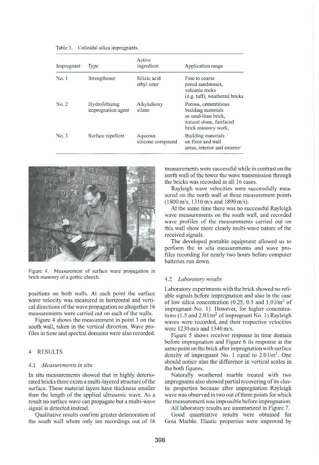
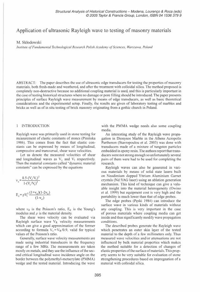
Table I. Colloidal silica impregnants.
Active Impregnant Type ingredient
No. I Strengthener Silicic acid ethyl ester
No. 2 Hydrofobizing Alkylalkoxy impregnation agent silane
No. 3 Surface repellent Aqueous
Application range
Fine to coarse pored sandstones, volcanic rocks (e.g. tuil), weathered bricks
Poraus, cementitious building materiaIs as sand- lime brick, natural stone, fa irfaced brick masonry work,
Building materiaIs silicone compound on fioar and wall
Figure 4. Measurement of surface wave prapagation in brick masonry of a gothic church.
positions on both walls. At each point the surface wave velocity was measured in horizontal and vertical directions ofthe wave propagation so altogether 16 measurements were carried out on each of the walls.
Figure 4 shows the measurement in point 3 on the south wall, taken in the vertical direction. Wave profiles in time and spectral domains were also recorded.
4 RESULTS
4.1 Measurements in situ
In situ measurements showed that in highly deteriorated bricks there exists a multi- Iayered structure ofthe surface. These materiallayers have thickness smaller than the length of the applied ultrasonic wave. As a result no surface wave can propagate but a multi-wave signal is detected instead.
Qualitative results confirm greater deterioration of the south wall where only ten recordings out of 16
areas, interior and exterior
measurements were successful while in contrast on the north wall ofthe tower the wave transmission through the bricks was recorded in ali 16 cases.
Rayleigh wave velocities were successfully measured on the north wall at three measurement points (1800 m/s, 1310 m/s and 1890 m/s).
At the same time there was no successful Rayleigh wave measurements on the south wall, and recorded wave profiles of the measurements carried out on this wall show more clearly multi-wave nature of the received signals.
The developed portable equipment allowed us to perform the in situ measurements and wave profiles recording for nearly two hours before computer batteries run down.
4.2 Laboratory results
Laboratory experiments with the brick showed no reliable signals before impregnation and also in the case of low silica concentration (0.25, 0.5 and 1.0 11m2 of impregnant No. 1). However, for higher concentrations (1.5 and 2.0 11m2 of impregnant No. 1) Rayleigh waves were recorded, and their respective velocities were 1230 m/s and 1340 m/s.
Figure 5 shows receiver response in time doma in before impregnation and Figure 6 its response at the same point on the brick after impregnation with surface density of impregnant No. 1 equal to 2.0 11m2 . One should notice also the difference in vertical scales in the both figures.
Naturally weathered marble treated with two impregnants also showed partial recovering of its elastic properties because after impregnation Rayleigh wave was observed in two out ofthree points for which the measurement was impossible before impregnation.
AlIlaboratory results are summarized in Figure 7. Good quantitative results were obtained for
Goia Marble. Elastic properties were improved by
398

mV 50;·······················:··· ·· ··········· ·· ··· · · .. .. ..... .. ... .... ..... ; .... .. .... ..... ..... ... :...................... . ... .. ... . .. .......... . 40;·······················:······· · ·········· · ···· .. . ....... . .......... .. ; .... . .................. ~............... . ...... . .......... . ....... .. . , 30[·· ··· ········ ·· ····· ···;······················· ... ... ..... ............ ; ........... .. ....... ... ;.. ..................... . ..................... , 20;·······················;·· ······ · ·· ·· · · ··· ·· · ·· ........... ... ......... ; .. . ................ . ... ~ . ..................... . ........... ....... .. . , 10: ·······················;······················· ...................... ; ..... . ......... . ..... : ................. . . 0:- .: :: "
:~~:::::::::::::::::::::::t::::::::::::: :: :::::::j:::::::::::::::::::::::~:::::::::::::::::::::::t:::::.:::::::::::::::::::::::::::::::: :::::::::j ·30:··· ·· ·· ·· ··············;·· ·····················;·· ... .......... ........ : ........... ... ... . ..... ~ ... .. . ..... . ..... . .. ... ; ................ . ..... . ; '40[· ·· ...... ··············;· ······················i····· .. ........ .. .. .... ; ....................... ; ........................ ; ....... .. . .............. ; .50; ............. . . . ....... : ... .... ........ . ....... ; . . .. .. . . ... .. . . .. .... . . : ....................... ~ ....................... : ...... ................. ;lIs 22.5 25.0 27.5 30.0 32.5 35.0 37.5
Figure 5. Receiver response for unimpregnated brick.
Figure 6. Receiver response for brick after impregnation.
MG fresh
brick o good
MGafter thermal cycle
~ unacceptable
marble natur. weathered
Figure 7. Summarized results of laboratory surface wave measurements showing the number and amount of impregnam used at each measurement position.
~r------------------------------------.
2500 t-----'&~--='-"'-='-='-'-<+~=-=-'--=------=------------.-'--oQ=---___j *. • +--'g 2000 t------=-.,,---------------------------___j
~ ..... - . -. ~ '500t---------~~~~~.------~r-------------4
g 1000t-------------------------------------___j
5OOt------------------------------------1
measurement POtnt
-+- ·freSh, no Impregatlon -(3- ·freSh, afler Impregatlon -â - Ihermal cycle.00 Impregnabon - )( - mennalcycle. atterUTlpfegnatlon
Figure 8. Surface wave ve locities for two specimens ofGoia Marble.
impregnation with impregnant No. 2 both for fresh and thermally weathered specimens.
Measured surface wave velocities are shown in Figure 8.
A lower surface wave velocitywas recorded for thermally weathered specimen than in the case ofthe fresh, intact marble. However, the impregnation procedure immediately improved wave propagation conditions in both specimens even for very low silica concentration (surface density of impregnant No. 2 equal to 0.25 11m2). Increase of silica concentration resulted in further slight increase ofthe surface wave velocity and this increase was somewhat higher for more deteriorated specimen. Nevertheless, the general result was the same for the both specimens, and the Rayleigh wave velocity after impregnation had almost the same value in both cases.
5 CONCLUSIONS
The developed portable equipment for Rayleigh wave measurement with 1.25 MHz ultrasonic edge transducers allowed us to measure surface wave velocity both in laboratory and in situo The equipment was also suitable for detection of changes of the elastic properties of impregnated surfaces of materiais encountered in historical structures.
In several cases impregnation of the material allowed us to measure surface wave in specimens where prior to impregnation no such a wave could be detected.
The most interesting result was for the Goia Marble. Impregnation ofthe specimens with hydrophobic impregnant No. 2 resulted in significant increase of the surface wave velocity. This increase was up to 50-70% for thermally weathered specimen. Increased
399

wave velocities for impregnated fresh and thermally weathered specimens were practically the same.
ACKNOWLEDGEMENTS
The research described in this paper was conducted with financiaI support of the EU 6 Framework Program (MCDUR, Contract G6RD-CT2000-00266, & ACOUTHERM, Contract GRD3-200 1-6000 I) as well as of the Polish State Committee fo r Scientific Research (63/E-89/SPB/5.PR UE/DZ 15012003-2004).
Samples of colloidal silica for impregnation treatment were kindly supported by Remmers-Poland.
REFERENCES
P\!ski, Z. 1984. Nowa metoda generowania fali powierzchniowej. In: 13 Krajowa Konferencja Badan Nieniszczqcych, Kozubnik. (in Polish) .
P\!ski, Z. & Ranachowski , 1. 1988. Patent Pending /42739, Poland.
PiniIíska, 1. 1986. Surface wave velocity as a laboratory nondestructive control of the rock properties. In ProC. 5th Intern. JAEG Congress, 20-25 October 1986, Buenos Aires. Rotterdam, Boston: Balkema.
Owino, 1.0. & Jacobs, LJ. 1999. Attenuation measurements in cement-based materiaIs using laser ultrasonics. Journal of Engineering Mechanics 125(6): 637-647 .
Sklodowski , M. , Piniríska, l, Lukaszewski, P. , Bobrowska, A. & Gutkiewicz. P. 2002. Report on Ultrasonic surface wave velocity measurements. MCDURACUTHERM 6FP Project (unpubl).
Sklodowski , M. , Piniríska, l ., Lukaszewski , P. , Bobrowska, A. & Gutkiewicz. P. 2003. Report on Ultrasonic surface wave velocity measurements. MCDURACUTHERM 6FP Project (unpubl).
Stavropoulou M., Exadaktylos G., Papamichos E., Larsen I. & Ringstad C. 2003 . Rayleigh wave propagation in intact and damaged geomaterials.Int. J Rock Mech and Min. Sei. 40(3): 377- 387.
Remmers (UK) Ltd. 2004. http://www.remmers.co.ukl
400