application of vector control technology for pmsm … the open automation and control systems...
TRANSCRIPT

Send Orders for Reprints to [email protected]
1334 The Open Automation and Control Systems Journal, 2014, 6, 1334-1341
1874-4443/14 2014 Bentham Open
Open Access Application of Vector Control Technology for PMSM Used in Electric Ve-hicles
Tingting Liu1,*, Guojin Chen1 and Shigang Li2
1School of Mechanical Engineering, Hangzhou Dianzi University, Hangzhou, 310018, China 2College of Mechanical and Electrical Engineering, Beijing Union University, Beijing, 100083, China
Abstract: Based on the equation of small pure electric vehicle (PEV) and the mathematic model of permanent magnet synchronous motor (PMSM), synchronous motor (PMSM), the dynamic model is presented for small PEV driven by PMSM. With space vector pulse width modulation (SVPWM) algorithm, a velocity and current double closed-loop simu-lation model of PMSM control system is build in Matlab7.6/Simulink environment. Simulation results show that: the sys-tem has the advantages of fast response, high precision, strong anti-interference ability, and this novel method offers a new thought way for designing and debugging driving system of PEV.
Keywords: PEV, PMSM, SVPWM, Vector control, Simulation.
1. INTRODUCTION
Electric vehicles with the advantage of no pollution, low noise, zero emission, high energy conversion efficiency, have become the trend of the automotive industry. As the main executive body, electric vehicle driving system has profound theoretical significance and practical value for the study of driving motor and its control system [1]. The PMSM with its simple structure, small size, light weight, small iner-tia, high power density, is very suitable for the limited space of electric vehicles; In addition, its high efficiency, high power factor, torque to inertia, strong overload capacity, high output torque especially at low speed, which means that the PMSM is also very suitable for the needs of starting and acceleration [2]. Therefore, a variety of factors have deter-mined that the PMSM has become one of the important choices for driving system of electric vehicles.
Currently there are many control strategies and algo-rithms for PMSM. Vector control is characterized by high accuracy, fast dynamic response, and wide speed range, but its control performance is easily influenced by the variation of motor parameters [3-5]; The performance of direct torque control is not affected by parameters, and it has high reliabil-ity, but more difficult to control [6, 7]; Single neuron PID control optimize the starting performance of the motor, but its control effect largely depends on the learning rate of neu-rons [8].
The operating environment and requirements of electric vehicles vary greatly, so different control strategies are adopted at different stages. In this paper, a composite control scheme is designed by employing the space vector pulse width modulation (SVPWM) technology and PI control
algorithm, a velocity and current double closed-loop simulation model of PMSM control system is build in Matlab7.6/Simulink environment, the dynamic performance of control system is being test under different speed when the electric vehicle traveling in the direct gear. Simulation results show that the system has good dynamic, steady-state performance and robustness. This novel method provides a theoretical basis and project reference for the design and implementation of the actual control system.
2. SYSTEM DESIGN
Vector control methods of PMSM mainly include: id=0
control, the maximum torque/current control, field weaken-ing control, the maximum output power control and etc, the-se several control methods can meet the requirements of dif-ferent operating characteristics.
A velocity and current double closed-loop control strate-gy is employed in this system, considering the characteristics of strong coupling, time-varying and nonlinear, the SVPWM algorithm is used in the inner loop; In order to enhance the robustness and anti-interference ability, PI speed controller is used in the outer loop. Schematic diagram of control system is shown in Fig. (1). The system consists of coordinate trans-formation, SVPWM, three-phase inverter, speed and position signal modules and PI controller.
3. MATHEMATICAL MODEL ANALYSIS
3.1. Mathematical Model of PMSM in the dq Coordinate System
For the speed PMSM, the damper windings on the rotor does not exist, therefore the mathematical model of PMSM in dq coordinate system is expressed as follows [9]:

Application of Vector Control Technology The Open Automation and Control Systems Journal, 2014, Volume 6 1335
Voltage equations:
ud=
d!d
dt"#!
q+ R
1id
uq=
d!q
dt+#!
d+ R
1iq
$
%
&&
'
&&
(1)
Stator flux equations:
!d= L
did+ L
mdi
f
!q= L
qiq
"#$
%$ (2)
Electromagnetic torque equation:
T
em= p[L
mdi
fiq+ L
d! L
q( ) " idiq]
(3)
Mechanical motion equation:
J
p
d!
dt= T
em"T
L (4)
In the above formula, u
d and
uq
are components of
stator voltage on dq axis; di and qi are components of the
stator current on dq axis; !
d and !
q are components of the
stator flux on dq axis; L
d, L
q are inductances of the stator
winding on dq axis; R
1 is stator resistance;
L
md is mutual
inductance between the stator and the rotor on d axis; i
f is
equivalent excitation current of permanent magnet; T
emis
electromagnetic torque of the motor; LT is load torque; J is
moment of inertia; p is number of rotor pole pairs; ω is the electric angular speed of the rotor.
3.2. Mathematical Model of the PEV and its Driving Sys-tem
Battery is the energy device; PMSM is the driving device; PEV runs through the transmission system. Therefore, before creating a mathematical model of PEV system, the mathe-matical model of an automotive transmission module should be analyzed [10].
The running equation of electric vehicles:
Ttqigi0!
T
r= G( f
0+ ku
a)cos" +
CD
Aua
2
21.15+
G sin" +#mdu
a
dt
(5)
The speed and motor output speed equation:
ua= 0.377
nr
i0i
g (6)
In the above formula, T
tq is torque acting on the drive
wheels; i0 is final drive transmission ratio;
ig
is
transmission gear ratio; !
T is the mechanical efficiency of transmission system; r is wheel radius; G is vehicle weight; f0 is coefficient that does not vary with speed; k is velocity coefficient;
u
ais vehicle speed; n is motor speed; ! is slope
angle; CD is air resistance coefficient; A is windward area; m is vehicle weight; δ is rotating mass conversion coefficient.
Fig. (1). Structure diagram of vector control for PMSM.

1336 The Open Automation and Control Systems Journal, 2014, Volume 6 Liu et al.
4. THE VECTOR CONTROL PRINCIPLE OF PMSM
4.1. Coordinate Transformation of PMSM
In the control process of PMSM, the actual current in ar-mature winding is three-phase alternating current iA,iB,iC, therefore, certain transformation should be done to get cur-rent components on d axis and q axis. First is the transform from three-phase stationary coordinate to two-phase station-ary coordinate, namely Clark transform:
i!
i"
#
$
%%
&
'
((=
2
3
1 ) 1
2) 1
2
03
2) 3
2
#
$
%%
&
'
((
iA
iB
iC
#
$
%%%%
&
'
((((
(7)
Then the transform from two-phase stationary coordinate to the synchronous rotating coordinate, namely Park transform:
id
iq
!
"
##
$
%
&&=
cos' (sin'sin' cos'
!
"##
$
%&&
i)
i*
!
"
##
$
%
&&
(8)
4.2. The Simulink Implementation of SVPWM Module
The SVPWM technology’s main idea is as follows: take the ideal flux path as a benchmark, when PMSM is powered by three-phase sine wave voltage, approach the benchmark flux circle with the actual flux produced by inverter’s 8 switch mode, and the motor could obtain a constant amplitude circular magnetic field (sine magnetic field), so as to achieve high performance. With the SVPWM technology, we select two adjacent effective vectors and the vector zero from these eight, and form the space voltage vector
U
rthat
needed according to their respective response time, the principle is shown in Fig. (2).
According to SVPWM principle, the real-time calcula-tion procedure of SVPWM signal is as follows:
1. The sector judgment
According to the relationship between U
!and
U
!, the
judgment is as follows:
a.When U
!> 0 , makes A=1, else A=0;
b.When
3U!"U
#> 0 , makes B=1, else B=0;
c.When ! 3U
"!U
#> 0 , makes C=1, else C=0.
The sector: N=A+2B+4C; U
! and U
! are components
on ! axis and ! axis of synthetic vector U
ref.
2. The calculation of X, Y, Z and T
1, T
2
T
1means the main vector’s operating time in current
working sector, T
2means vice-vector’s operating time, the
operating time T
1 and T
2 can be calculated as follows.
X =2U!
2Udc
tz
Y =( 3U! +U" )
2Udc
tz
Z =( 3U! #U" )
2Udc
tz
$
%
&&&&&
'
&&&&&
(9)
When T
1+T
2! t
z> 0 , and
t
z is switching period, calcu-
late the new value of T
1and
T
2, make
T
1= T
1t
z/ (T
1+T
2) ,
Fig. (2). Basic space voltage vector.
Application of Vector Control Technology The Open Automation and Control Systems Journal, 2014, Volume 6 1337
T
2= T
2t
z/ (T
1+T
2) . For different sectors, the assignments of
T
1and
T
2 can be derived from Table 1.
3. The determination of vector switching points
T
cm1,T
cm2,T
cm3
Ta= 0.25(T !T
1!T
2)
Tb= T
a+ 0.5T
1
Tc= T
b+ 0.5T
2
"
#$$
%$$
(10)
For different sectors, the assignments of T
cm1,T
cm2,T
cm3
can be derived from Table 2.
Compare the isosceles triangular wave with T
cm1,T
cm2,T
cm3
(isosceles triangular wave is produced by integrating the pulse generator), we can get the symmetric SVPWM wave-form.
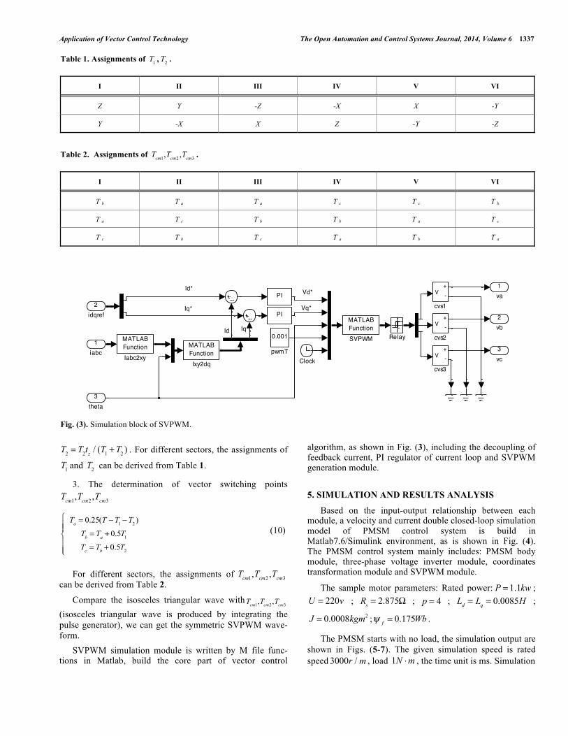
SVPWM simulation module is written by M file func-tions in Matlab, build the core part of vector control
algorithm, as shown in Fig. (3), including the decoupling of feedback current, PI regulator of current loop and SVPWM generation module.
5. SIMULATION AND RESULTS ANALYSIS
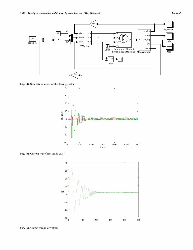
Based on the input-output relationship between each module, a velocity and current double closed-loop simulation model of PMSM control system is build in Matlab7.6/Simulink environment, as is shown in Fig. (4). The PMSM control system mainly includes: PMSM body module, three-phase voltage inverter module, coordinates transformation module and SVPWM module.
The sample motor parameters: Rated power: P = 1.1kw ; U = 220v ;
R
s= 2.875! ;
p = 4 ;
L
d= L
q= 0.0085H ;
J = 0.0008kgm2 ;
!
f= 0.175Wb .
The PMSM starts with no load, the simulation output are shown in Figs. (5-7). The given simulation speed is rated speed 3000r / m , load 1N !m , the time unit is ms. Simulation
Table 1. Assignments of T
1, T
2.
I II III IV V VI
Z Y -Z -X X -Y
Y -X X Z -Y -Z
Table 2. Assignments of T
cm1,T
cm2,T
cm3.
I II III IV V VI
T b T a T a T c T c T b
T a T c T b T b T a T c
T c T b T c T a T b T a
Fig. (3). Simulation block of SVPWM.
Vd*
Vq*
Id*
Iq*
Id Iq
3vc
2vb
1va
0.001
pwmT
PI
PI
V+-
cvs3
V+-
cvs2
V+-
cvs1
MATLABFunctionSVPWM Relay
MATLABFunctionIxy2dq
MATLABFunctionIabc2xy
Demux
Demux
Demux
Clock
3theta
2idqref
1iabc
1338 The Open Automation and Control Systems Journal, 2014, Volume 6 Liu et al.
Fig. (4). Simulation model of the driving system.
Fig. (5). Current waveform on dq axis.
0 100 200 300 400 500 -30
-20
-10
0
10
20
30
40
t
Nm
Fig. (6). Output torque waveform.
Id*
Iq*
+- v
vbc
.8
speed ref
is_abc (A)
PI
0
Udq
A
B
C
Tm
m
Permanent MagnetSynchronous Machine
iabc
idqref
theta
v a
v b
v c
PWM inv.
m
is_abc
is_dq
v s_dq
we
theta
MeasurementLoad
Idq
-K-
-K-
0 500 1000 1500 2000 2500 3000-30
-20
-10
0
10
20
30
40Á«»‡² á−−Â˙Ê¿¿ØÖƲ »Ö±ÖáµçÊ’ ×̈ž Í
t /ms
id /i
q ( A
)

Application of Vector Control Technology The Open Automation and Control Systems Journal, 2014, Volume 6 1339
0 100 200 300 400 500 0
50
100
150
200
250
300
350
400
t
rad/s
Fig. (7). Velocity waveform.
Fig. (8). Current on dq axis under variable load.
results show that: with this control method, we can achieve better control performance. The current, output torque and velocity reach stable values within 0.2 seconds, the start speed of PMSM is fast, and we can accurately track the giv-en speed.
Figs. (8-10) show response to load mutation, the initial load is 1N.m, and at 0.02 seconds, the load suddenly rises to 10N.m. The system response shows that: with double ring structure, we can quickly track the changes of torque, as is shown in Fig. (9); In case of load, speed can track the given value after a short volatility, which is shown in Fig. (10). Fig. (8) shows that, currents on dq axis both are straight flow with slight fluctuation, the output torque is proportional to iq, the complete decoupling is realized. These results are
consistent with the pre-analysis for the control system, the expected control effect achieved, and the control method is proved feasible.
CONCLUSION
According to the needs of small PEV, based on the math-ematical analysis of PMSM and PEV, a velocity and current double closed-loop control system is designed by employing the SVPWM technologies and PI algorithm. The results show that: the system has fast response speed, good robust-ness and stronger anti-interfere ability, which could meet the city traffic demand of PEV. This novel method offers a new thought way for designing and debugging driving system of small PEV.
0 500 1000 1500 2000 2500 3000 3500 4000 4500-30
-20
-10
0
10
20
30
40Ì ´ÅȬײ µç»úÂ˙Ê¿¿ØÖƇ‰Ã棺d-qÖáµçÊ’
t
id-iq
/A
iq
id

1340 The Open Automation and Control Systems Journal, 2014, Volume 6 Liu et al.
CONFLICT OF INTEREST
The authors confirm that this article content has no con-flict of interest.
ACKNOWLEDGEMENTS
This research was financially supported by the National Natural Science Foundation of China (No.51305112) and the Natural Science Research Fund of Zhejiang Province (No. 2010R50G2040003).
REFERENCES [1] M. Wang, and J. Wang, Electric Vehicle and its Performance Op-
timization, Machine Press: Beijing 2010.
[2] S. Song, J. Gong, W. Lin, and G. Wang, “Modeling and simulation of space vector control system for pure electric vehicle driven by permanent magnet synchronous motor”, Journal of Wuhan Univer-sity of Technology, vol. 34, no.4, pp. 118-122, 2012.
[3] C. Wang, Y. Ji, H. Luan, and Z. Zhang, “Simulation of PMSM sensorless vector control system based on Matlab/Simulink”, Jour-nal of Jilin University (Information Science Edition), vol. 27, no. 1, pp. 17-22, 2009.
[4] C. Zhang, F. Wang, S. Li, and D. Yang, “The vector control of pmsm based on MATLAB/Simulink”, Journal of Soochow Univer-sity (Engineering Science Edition), vol. 31, no. 3, pp. 63-67, 2011.
[5] A. Li, H. Deng, and L. Xu, “Fuzzy-PID-based PMSM vector con-trol simulation”, Chinese Journal of Construction Machinery, vol. 11, no. 1, pp. 25-30, 2013.
[6] B. Wang, Y. Wang, and Z. Wang, “Direct torque control of perma-nent magnet synchronous motordrives using space vector modula-tion”, Electric Machines and Control, vol. 14, no. 6, pp. 45-50, 2010.
Fig. (9). Output torque under variable load.
Fig. (10). Velocity under variable load.

Application of Vector Control Technology The Open Automation and Control Systems Journal, 2014, Volume 6 1341
[7] Y. Shi, H. Xu, H. Ruan, and H. Huang, “Permanent magnet syn-chronous motor direct torque control (DTC) system”, Techniques of Automation and Applications, vol. 26, no. 2, pp. 90-92, 2007.
[8] Y. Zhang, and Z. Shu, “Simulation research of sliding mode control based on permanent magnet synchronous motor”, Machine Tool & Hydraulics, vol. 36, no. 7, pp. 288-292, 2008.
[9] K. B. Bimal, Modern Power Electronics and AC Drives, Beijing: Machine Press, 2006.
[10] G. Wang, J. Ma, P. Yang, and M. Yan, “Dynamic modeling and simulation of starting and acceleration for electric vehicle”, Journal of Chang’an University (Natural Science Edition), vol. 29, no. 6, pp. 98-102, 2009.
Received: September 16, 2014 Revised: December 23, 2014 Accepted: December 31, 2014
© Liu et al.; Licensee Bentham Open.
This is an open access article licensed under the terms of the Creative Commons Attribution Non-Commercial License (http://creativecommons.org/licenses/by-nc/3.0/) which permits unrestricted, non-commercial use, distribution and reproduction in any medium, provided the work is properly cited.