application of the needle optimization technique to the design of optical coatings
TRANSCRIPT
Application of the needle optimizationtechnique to the design of optical coatings
Alexander V. Tikhonravov, Michael K. Trubetskov, and Gary W. DeBell
The authors’ experience with the application of the needle optimization technique to the design of opticalcoating is summarized. A physical interpretation of the technique is provided, and its main features areidentified. Guidelines on the application of the needle optimization technique to various types of designproblems are given. © 1996 Optical Society of America
1. Introduction
The problem of optical coating design was first for-mulated as an optimization problem by Baumeisterin 1958.1 This approach is now themost widely useddesign technique for optical thin films ~see Refs. 2–4!.It is possible to apply all the powerful tools of moderncomputational mathematics to the design of opticalcoatings when the design problem is formulated as anoptimization problem. Nevertheless, in many casesthe numerical solution of the resulting optimizationproblems are extremely difficult because of the largenumber of local minima in the merit function. Vir-tually all optimization methods are subject to conver-gence at local minima, and, for this reason, a searchfor the globalminimum or even a good local minimumis a formidable problem.The solution of the design problem, i.e., the opti-
mization of the merit function, is greatly simplifiedwhen a good starting design is known. Unfortu-nately, good starting designs are not readily availablefor many modern design problems. To solve suchproblems, one ought to use nonlocal synthesis designtechniques.4 During the past few years, a powerfulnew design technique, needle optimization, has beendeveloped. The basic idea of this technique was firstproposed5 in 1982, and the first computer code thatimplemented it was developed for use on the RussianBESM-6 mainframe.6 Since its first implementa-tion, the computer codes and mathematical algo-
A. V. Tikhonravov and M. K. Trubetskov are with the ResearchComputer Center, Moscow State University, Vorob’evy Gory, Mos-cow, Russia 119899. G. W. DeBell is with DeBell Design, 619Teresi Lane, Los Altos, California 94024.Received 14 November 1995; revised manuscript received 16
February 1996.0003-6935y96y285493-16$10.00y0© 1996 Optical Society of America
rithms have been continually improved, and severalgenerations of new computer codes have been devel-oped.7,8From the experience accumulated in the solution of
a large number of design problems, it is now possibleto identify the most essential elements of the needleoptimization technique. It is also possible to artic-ulate the primary peculiarities of its application, de-pending on the design problem being considered.Insight into these peculiarities is provided by theresults that follow from the maximum principle inthin-film optics.9,10In Section 2 the basic physical concepts underlying
the needle optimization technique are considered andits most essential features are listed. Sections 3 and4 contain guidelines on the application of the tech-nique to various classes of design problems.
2. Physical Interpretation of the Needle OptimizationTechnique and its Main Features
In this paper we do not delve deeply into the math-ematical details of the needle optimization techniquebut instead address our attention to its physical in-terpretation. A discussion of the most up-to-datemathematical algorithms for this technique can befound in Ref. 11.From a physical point of view, the main idea of the
optimization processes as applied to optical coatingdesign can be described as follows. A multilayer op-tical coating is an interference structure whose spec-tral performance is due to the interference effectsamong the light waves reflected from its various layerboundaries. The interference effects are determinedby the phases and the amplitudes of the reflectedwaves. The numerical measure of the correspon-dence between the actual and the desired spectralcharacteristics of the design is provided by the meritfunction. The smaller the merit function, the closer
1 October 1996 y Vol. 35, No. 28 y APPLIED OPTICS 5493

the correspondence between the target and the actualdesign characteristics. When the merit function isoptimized with respect to the layer thicknesses, thephase relationships among all reflected waves arebeing changed. If optimization with respect to thelayer refractive indices is performed, in effect the am-plitudes of the reflected waves are also beingchanged. The mathematical optimization process,as it relates to a thin-film design, is finished when itbecomes impossible to minimize the merit functionfurther because of the interference effects among thewaves reflected from the existing layer boundaries.Clearly, to proceed further with the optimization of
the merit function, one ought to introduce into con-sideration some new physical effects. This can bedone by means of the insertion of new layers into theexisting multilayer structure. Such insertions areequivalent to changing the refractive-index profile ofthe multilayer structure ~see Fig. 1!. These varia-tions are referred to as needle variations of therefractive-index profile.12 If new layers are insertedin the right places, new interference effects associ-ated with these layers will improve the correspon-dence between the desired and the actual spectralcharacteristics of the design under consideration.The question is how to find the proper places to insertnew layers. The essence of the needle optimizationtechnique is that its algorithm identifies the properplaces ~if they exist! to insert new layers that willimprove the merit function. The algorithm will alsoidentify which layer material, from a preselectedgroup of materials, will provide the greatest improve-ment.Consider a single needle variation of the refractive-
index profile being inserted at some point z inside thecurrent multilayer structure ~z is a physical thick-
Fig. 1. Transformation of the optical coating that is due to theinsertion of new layers: solid lines in A, refractive-index profilebefore the insertion; solid lines in B, refractive-index profile afterthe insertion; dashed curve in A, function P~z!, the key function ofthe needle optimization technique that determines the thicknessesand insertion points; d1, d2, . . . , thicknesses of new layers.
5494 APPLIED OPTICS y Vol. 35, No. 28 y 1 October 1996
ness of a coating!. Let d be the thickness and n bethe refractive index of a new layer. Denote as F amerit function being specified for the design problemunder consideration. It is possible to show that thevariation of the merit function that corresponds to asingle needle variation of the refractive-index profilecan be presented as a series with respect to the thick-ness of a new layer12:
dF 5 P1~z, n!d 1 P2~z, n!d2 1 · · · . (1)
The coefficients of this series depend on the position ofthe new layer inside the current film structure as wellas on the refractive index of the new layer.One of the most critical elements of the needle
optimization technique is that there is an analyticalgorithm that allows the calculation of the change inthe merit function as a function of the index andposition of a new layer without the actual insertion ofa new layer.11 The algorithm is rather complicatedbut it is extremely efficient from the computationalpoint of view.Usually a limited number of well-defined materials
are used in the synthesis of optical coatings. Thusthe refractive index of a new layer cannot assume anarbitrary value. Denote as n1, n2, . . . , nJ the refrac-tive indices of the materials that are available for usein the synthesis process. A function of the formgiven below is used to identify the most appropriateposition to insert new layers within the existing de-sign as well as to determine which of the availablematerials is the best choice for the new layer:
P~z! 5 min1,j,J
Pj~z, nj!. (2)
The process of inserting new layers is illustrated inFig. 1. The solid lines in Fig. 1A represent therefractive-index profile of a coating before the inser-tions of new layers ~the z axis is normal to the surfaceof the optical coating!. Coordinate z5 0 correspondsto the boundary of the coating with the substrate, andcoordinate z 5 za marks the boundary with the am-bient medium. Refractive indices of the substrateand the ambient medium, ns and na, respectively, areindicated near the corresponding boundaries.In general, all places where the P function is neg-
ative may be considered as appropriate places for theinsertion of new layers. At the same time, betterresults are usually obtained when the insertions oc-cur at the places where the P function has its mostnegative values. Such places are marked on the zaxis in Fig. 1A, and new layers with thicknesses d1,d2, and d3 are shown.In the case of two-material optical coatings, the
refractive indices of new layers are of the alternatematerial to that of the refractive indices of those lay-ers where insertions take place. In the case of coat-ings with more than two materials, refractive indicesof new layers are determined as those nj values thatprovide the minimum in Eq. ~2! at the correspondingz points.
It can be rigorously shown from a mathematicalpoint of view that when the thicknesses of new layersd1, d2, . . . , are small enough, the insertion of newlayers at places where the P function is negativeleads to a decrease of the merit function. However,in practice, new layers are not required to be thin.Their thicknesses are determined so as to cause themaximum decrease of the merit function, and quiteoften they turn out to be big enough.The refractive-index profile of a new coating, ob-
tained after the insertion of new layers, is shown inFig. 1B. It is quite possible that phase shifts be-tween the waves reflected from its boundaries are notoptimally adjusted. Thus the optimization of thiscoating with respect to the thicknesses of its layersmay effect a further decrease in the merit function.In general, the synthesis procedure based on the
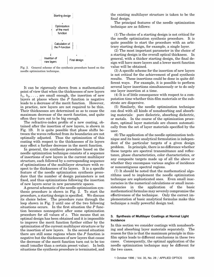
needle optimization technique consists of a sequenceof insertions of new layers in the current multilayerstructure, each followed by a corresponding sequenceof optimizations of the multilayer structure with re-spect to the thicknesses of its layers. It is a specificfeature of the needle optimization synthesis proce-dure that the number of design parameters is notfixed, and thus optimizations following the insertionof new layers occur in new parametric spaces.A general schematic of the needle optimization syn-
thesis procedure is shown in Fig. 2. To start theprocedure, a starting design is specified. We discussits choice below. The procedure runs through theloop shown in Fig. 2 until one of the two followingsituations occurs. In the first situation the P func-tion becomes nonnegative after some optimizationprocedure for all values of z. This means that anoptimal design has been obtained and it is impossibleto improve the merit function further either by theoptimization of the current multilayer structure or bythe insertion of new layers. In the second situationthere are still some regions where the P function isnegative but the thicknesses of new layers that causethe decrease of the merit function turn out to be toosmall ~smaller than a certain preset value!. In bothsituations the synthesis procedure is terminated, and
Fig. 2. General scheme of the synthesis procedure based on theneedle optimization technique.
the existing multilayer structure is taken to be thefinal design.The principal features of the needle optimization
technique are as follows:
~1! The choice of a starting design is not critical forthe needle optimization synthesis procedure. It isquite possible to start the procedure with an arbi-trary starting design, for example, a single layer.
~2! The most important parameter in the choice ofa starting design is the overall optical thickness. Ingeneral, with a thicker starting design, the final de-sign will have more layers and a lower merit functionvalue will be obtained.
~3! A specific scheme for the insertion of new layersis not critical for the achievement of good synthesisresults. These insertions could be done in quite dif-ferent ways. For example, it is possible to performseveral layer insertions simultaneously or to do onlyone layer insertion at a time.
~4! It is of little consequence with respect to a com-putation time whether thin-filmmaterials or the sub-strate are dispersive.
~5! Similarly, the needle optimization techniquecan deal with all kinds of nonabsorbing and absorb-ing materials: pure dielectric, absorbing dielectric,or metals. In the course of the optimization proce-dure, optimal layer materials are chosen automati-cally from the set of layer materials specified by theuser.
~6! The application of the needle optimization tech-nique and its basic analytical formulation is indepen-dent of the particular targets of a given designproblem. In principle, there is no difference whetherthese targets are spectral transmittance and reflec-tance, phase characteristics, color characteristics, orany composite targets made up of all the above orwhether they encompass various angles of incidenceor noncontiguous spectral regions.
~7! It should be noted that the mathematical algo-rithms used to implement the needle optimizationtechnique are sophisticated ones. Even small inac-curacies in the numerical calculations or small incon-sistencies in the application of the basicmathematical formulasmay severely compromise theeffectiveness of the technique. Only the correct im-plementation of basic analytical formulas make thistechnique a really powerful design tool.
3. Synthesis of Multilayer Coatings at Normal LightIncidence
In this section we consider coatings with nonabsorb-ing and absorbing layer materials separately. Thereason for this is that the maximum principle in thin-film optics leads to different conclusions in these twocases. Consequently, the optimal application of theneedle optimization technique may be different forthe two cases.
1 October 1996 y Vol. 35, No. 28 y APPLIED OPTICS 5495
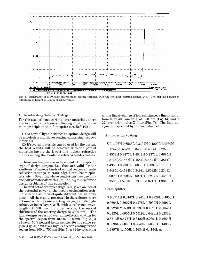
Fig. 3. Reflectance of a 40-layer antireflection coating obtained with the one-layer starting design, 24H. The displayed range ofreflectance is from 0 to 0.05 in absolute values.
A. Nonabsorbing Dielectric Coatings
For the case of nonabsorbing layer materials, thereare two basic conclusions following from the maxi-mum principle in thin-film optics ~see Ref. 10!:
~1!At normal light incidence an optimal design willbe a dielectric multilayer coating comprising just twomaterials.
~2! If several materials can be used for the design,the best results will be achieved with the pair ofmaterials having the lowest and highest refractiveindices among the available refractive-index values.
These conclusions are independent of the specifictype of design targets, i.e., they are valid for thesynthesis of various kinds of optical coatings: anti-reflection coatings, mirrors, edge filters, beam split-ters, etc. Given the above conclusions, we use onlyone pair of materials with nL 5 1.45, nH 5 2.35 for thedesign problems of this subsection.The first set of examples ~Figs. 3–7! gives an idea of
the potential power of the needle optimization tech-nique in the solution of quite different design prob-lems. All the results presented in these figures wereobtained with the same starting design, a single high-refractive-index layer, 24H, with a reference wave-length of 500 nm ~in other words, the opticalthickness of the starting design is 3000 nm!. Thefinal designs are a 40-layer antireflection coating forthe spectral region from 400 to 1200 nm ~Fig. 3!, a34-layer 50% neutral beam splitter for the same re-gion ~Fig. 4!, a 29-layer high-reflection coating for theregion from 400 to 700 nm ~Fig. 5!, a 31-layer coating
5496 APPLIED OPTICS y Vol. 35, No. 28 y 1 October 1996
with a linear change of transmittance, a linear ramp,from 0 at 400 nm to 1 at 800 nm ~Fig. 6!, and a27-layer tristimulus X filter ~Fig. 7!. The final de-signs are specified by the formulas below.
Antireflection coating:
S 0.1103H 0.6563L 0.3192H 0.4200L 0.4930H
0.1747L 2.5677H 0.3436L 0.4085H 2.7275L
0.4579H 0.3477L 1.4849H 0.2372L 0.6685H
0.8768L 0.1467H 1.4584L 0.4524H 0.3814L
1.4966H 0.2381L 0.6603H 0.8837L 0.1135H
1.5485L 0.4524H 0.3498L 1.6062H 0.2349L
0.6093H 0.8696L 0.0901H 1.6217L 0.4350H
0.3535L 1.5733H 0.1939L 0.6211H 1.3048L A.
Beam splitter:
S 0.0711H 0.8142L 0.2413H 0.7928L 0.4858H
0.5604L 0.8002H 0.4178L 0.7959H 0.5991L
0.3728H 2.9718L 0.3797H 0.4021L 2.9052H
0.3120L 0.6005H 0.5519L 0.6480H 0.3230L
2.6713H 0.4777L 0.3422H 2.0391L 0.4654H
0.3096L 2.5050H 0.9640L 0.5068H 1.1436L
1.2897H 1.4506L 1.7634H 0.4154L A.

Fig. 4. Transmittance of a 34-layer neutral beam splitter obtained with the same starting design as in Fig. 3. The displayed range oftransmittance is from 0.49 to 0.51 in absolute values.
High reflector:
S 0.8926H 0.9898L 0.9927H 0.9607L 0.8611H
0.7616L 0.8590H 0.9563L 0.9850H 0.9801L
0.9338H 0.8197L 0.7938H 0.9187L 0.9994H
1.0552L 1.2505H 1.4073L 1.1121H 1.0855L
1.1558H 1.4139L 1.1923H 1.0962L 1.1288H
1.4949L 1.2206H 1.0852L 1.1455H A.
Fig. 5. Reflectance of a 29-layer high-reflection coating obtained with the same starting design as in Fig. 3. The displayed range ofreflectance is from 0 to 1 in absolute values.
1 October 1996 y Vol. 35, No. 28 y APPLIED OPTICS 5497

Fig. 6. Transmittance of a 31-layer ramp coating obtained with the same starting design as in Fig. 3. The displayed range oftransmittance is from 0 to 1 in absolute values.
Ramp:
S 0.0980H 0.7182L 0.4055H 0.4722L1.0244H
0.2855L 0.7949H 0.8614L 0.3311H 0.8507L
0.8898H 0.3578L 0.7922H 0.9370L 0.4367H
0.6559L 0.9555H 0.5975L 0.4923H 0.9518L
0.8196H 0.4004L 0.8714H 0.9406L 0.5694H
0.6332L 0.9345H 0.9234L 0.9071H 0.9613L
1.0538H A.
Fig. 7. Transmittance of a 27-layer X filter obtained with the same starting design as in Fig. 3. The displayed range of transmittanceis from 0 to 1 in absolute values.
5498 APPLIED OPTICS y Vol. 35, No. 28 y 1 October 1996

Fig. 8. Transmittance of a 41-layer X filter obtained with the one-layer starting design, 40H. The displayed range of transmittance isfrom 0 to 1 in absolute values.
X filter:
S 0.4524H 0.3206L 0.5520H 1.3012L
0.2443H 0.3393L 1.2612H 1.6863L
1.2118H 1.2345L 0.3495H 0.2040L
1.2583H 1.4485L 1.5397H 1.0529L
1.0278H 0.5734L 0.4477H 1.0117L
1.8081H 1.1005L 0.9664H 0.8521L
0.8101H 0.8959L 0.6966H A.
In all cases, S stands for the substrate that is aglass with a refractive index of 1.52, A stands for air~ambientmedium!, andH and L are quarter-waves atl 5 500 nm.In all cases, the merit function was defined as
MF 5 H1N (j51
N Ff ~lj! 2 fjDfj
G2J1y2
, (3)
where f is the actual spectral characteristic ~trans-mittance or reflectance in the case of Figs. 3–7!, lj arewavelength points from a given wavelength grid withthe total number ofN points, fj are target values, andDfj are specified tolerances at these points.The target values at the wavelength grid points are
marked by crosses in Figs. 3–7. The total number ofspectral points N is equal to 80 in the case of Figs. 3and 4 and to 81 in the case of Figs. 5–7. The toler-ances in all cases were set to be equal to 0.01. Thusthe merit function value represents an average devi-ation of the actual spectral dependence from the tar-get expressed as a percentage. The final designs are
schematically represented by the bar graphs under-neath the spectral plots. The bar graph is scaled tothe physical thicknesses of the layers.The average residual reflectance of the antireflec-
tion coating is less than 0.6% ~MF 5 0.569!, the av-erage deviation of the beam-splitter transmittancefrom 50% is close to one hundredth of a percent~MF 5 0.0127!, the average reflectance of a high-reflection coating is more than 99.4% ~MF 5 0.593!,the transmittance of the ramp is close to the lineardependence with the deviation’s being less than onetenth of a percent ~MF5 0.0996!, and the deviation ofthe X-filter transmittance from the specified targetsis ;1% ~MF 5 1.079!.Using the last example, the X filter, we demon-
strate the impact of the overall thickness of the start-ing design on the final designs. In a set ofcalculations the thickness of a single high-index-layerstarting design was increased, and, as a result, finaldesigns that have more layers and lower merit func-tion values were obtained. With the starting design,32H, the final design has 29 layers and the meritfunction value is equal to 0.672; when the startingdesign thickness is increased to 36H, the final designis a 37-layer coating with MF 5 0.455. Finally, whenthe starting design thickness is increased to 40H, thefinal design is a 41-layer coating withMF5 0.259. Thetransmittance of the last design is shown in Fig. 8.The indirect connection between the total number
of layers of the final design and the total optical thick-ness of a starting design can be used to achieve themost acceptable compromise between the accuracy ofthe fit to the design targets and the total number oflayers in the design.
1 October 1996 y Vol. 35, No. 28 y APPLIED OPTICS 5499

Fig. 9. Transmittance of a 56-layer mirror with the suppressed secondary reflection zone. The displayed range of transmittance is from0 to 1 in absolute values.
Evidently, in most cases it is impossible to predictthe relationship between the total number of layersin the final design and the corresponding value of themerit function. But this relationship is quite essen-tial for the choice of the most practical design. Withthe needle optimization technique it is always possi-ble to obtain a set of designs with an increasing num-
5500 APPLIED OPTICS y Vol. 35, No. 28 y 1 October 1996
ber of layers and correspondingly decreasing meritfunction values and then to choose the most admis-sible solution to the design problem.It is well known that the difficulty of the multilayer
design problem grows as the number of design pa-rameters ~i.e., the number of layers! in the coatingincreases. The next set of examples ~Figs. 9–11!
Fig. 10. Transmittance of a 100-layer filter with two 40-nm high-reflection zones at 440 and 580 nm. The displayed range of trans-mittance is from 0 to 1 in absolute values.

Fig. 11. Transmittance of a 99-layer filter with two 40-nm high-reflection zones at 540 and 690 nm. The displayed range of transmit-tance is from 0 to 1 in absolute values.
demonstrate that the needle optimization techniquemay be successfully applied to the design problems inwhich the total numbers of layers are necessarilylarge. This set of examples relates to the problemsin which various rugate filter design techniques13–19are usually applied. As a practical matter, multi-layer designs with alternative layer materials may besubstituted for the rugate designs. Such quasi-rugate multilayers usually have a large number oflayers. For this reason, the design of multilayersthat emulate properties found in rugate design is acomplicated problem.Figure 9 demonstrates the result of the synthesis of
the high-reflection mirror with a suppressed second-ary reflection zone. The design targets for this prob-lem were specified as follows: T 5 1 in the spectralrange from 300 to 900 nm, and T 5 0 for the spectralrange from 1000 to 1200 nm. To solve the problem,a 17-layer quarter-wave mirror centered at 1100 nmwas used as a starting design. The final design is a56-layer coating.It should be noted that a solution to this problem is
possible with other starting designs, for example, aone-layer starting design as in the above-mentionedexamples. But it is certainly more natural to usestarting designs that feature at least some of therequired spectral properties of the final design.Usually such a choice facilitates the solution of thedesign problem.Figures 10 and 11 show the transmittances of two
narrow-band reflectors with reflection bands of40-nm width. In the case of Fig. 10, reflection bandsare centered at 440 and 580 nm, and in the case ofFig. 11 reflection bands are at 540 and 690 nm. In
both cases, high transmission in all other regions inthe range from 400 to 800 nm is required.The designs obtained with the needle optimization
technique have 100 and 99 layers. They are sche-matically represented in the lower parts of Figs. 10and 11, respectively. It should be noted that quasi-rugate multilayers obtained with the rugate synthe-sis approaches have considerably more layers.17
B. Coatings with Absorption in Layer Materials
As soon as one considers coatings with an absorptionin layer materials, the consequences following fromthe maximum principle in thin-film optics9,10 differfrom those listed at the beginning of Subsection 3.A.Even in the case of dielectric coatings with a rela-tively small absorption in the layer materials, opti-mal designs may contain layers of more than twomaterials. A good illustration of this fact is providedby the contest problem discussed at the Optical In-terference Coating ’95 Topical Meeting.20When a number of coating materials are used for
the synthesis, the question of optimization with re-spect to the layer refractive indices arises. It is ev-ident that layer thicknesses and layer refractiveindices are two heterogeneous sets of variables.Layer thicknesses can be varied continually whereasrefractive indices can take only a limited number ofdiscrete values. The last fact hampers the practicalapplication of standard optimization routines be-cause they perform an optimization by continualchanges of variables.There are even more problems with the search for
the optimal refractive-index values when layer ma-terials are absorbing and dispersive. For example, a
1 October 1996 y Vol. 35, No. 28 y APPLIED OPTICS 5501

Fig. 12. Reflectance of a 39-layer metal-dielectric edge filter for the spectral band from 400 to 1600 nm. The displayed range ofreflectance is from 0 to 1 in absolute values.
well-elaborated Fourier-transform technique dealswith only nonabsorbing and nondispersive refractiveindices.A specific feature of the needle optimization tech-
nique is that it changes refractive indices in incre-ments that correspond to a predetermined set of realmaterials specified by the designer. Thus there areno problems with the feasibility of the solutions.There is no difference for the analytic algorithms ofthe needle optimization technique whether or not thelayer materials are absorbing or dispersive.In an actual problem, the search for optimal
refractive-index values occurs as follows. New in-dex values are introduced when new layers are in-serted into the existing multilayer. These valuesare chosen according to Eq. ~2! ~see Section 2 fordetails!. During the subsequent optimizations oflayer thicknesses, layers with nonoptimal index val-ues become smaller and smaller, and finally theselayers disappear. At the same time, thicknesses oflayers with the best-suited refractive indices will taketheir optimal values.Figure 12 illustrates the design of a coating with an
absorptive and dispersive layer material. The syn-thesis targets were R 5 1 in the spectral range from400 to 750 nm and R 5 0 in the spectral range from800 to 1600 nm. Along with two dielectric materialswith nL 5 1.45 and nH 5 2.35, nickel was used in thesynthesis procedure. The refractive-index data fornickel were specified according to the American In-stitute of Physics Handbook.21 A 25-layer quarter-wave dielectric mirror centered at 500 nm was usedas a starting design. The final design is a 39-layercoating with the second, the sixth, and the twelfthlayers made of nickel.
5502 APPLIED OPTICS y Vol. 35, No. 28 y 1 October 1996
4. Synthesis of Multilayer Coatings at Oblique LightIncidence
In general, the consequences from the maximumprinciple in thin-film optics at normal and obliquelight incidence are different.9,10 At the same time, inthe case of pure dielectric coatings, more detailedanalysis22 shows that for the case of s polarization atthe conclusions of the beginning of Section 3 arevalid. These conclusions are also valid for the caseof p-polarization at angles of incidence that satisfythe condition sin ua , nLy~=2na!, where nL is thelowest film material refractive index.To highlight the difference between the normal and
the oblique light incidence and also the differencebetween s and p polarization, it is worthwhile to re-view the effective refractive indices for both s- andp-polarized light. At oblique light incidence, the ef-fective refractive indices of a layer with a refractiveindex n are defined as23
neffs 5 ~n2 2 na
2 sin2 ua!1y2, (4)
neffp 5 n2y~n2 2 na
2 sin2 ua!1y2. (5)
Here na is the refractive index of the ambient me-dium, ua is the incidence angle, and indices s and prelate to the s and the p cases, respectively.Figure 13 shows the behavior of the effective refrac-tive indices as functions of the film index for the casein which ambient medium is glass ~na 5 1.52! and theincidence angle is 45°.Effective refractive indices for s-polarized light are
always less than corresponding n values, whereaseffective refractive indices for p-polarized light arealways more than the corresponding n values. The

essential issue, however, is not the absolute values ofthe effective refractive indices but how these valuescompare with each other. This is the consequence ofthe fact that spectral characteristics of a coating areinvariant with respect to the simultaneous multipli-cation of all indices ~including substrate and ambientmedium ones! to a certain value.23The concept of effective refractive indices allows the
designer to reduce the synthesis problem in the caseof light of a certain polarization to the same form asin the case of normal incidence. This explains why
Fig. 13. Effective refractive indices for s- and p-polarized light, nsand np, respectively ~na 5 1.52, ua 5 45°!.
the conclusions of Section 3 are valid for both s- andp-polarized light when they are considered sepa-rately.It is seen from Fig. 13 and it can be rigorously
shown that the ratio of the effective refractive indicesof two arbitrarymaterials in the s case is alwaysmorethan the ratio of the corresponding n values. On theother hand, this ratio in the p case is always less thanthe ratio of the actual refractive-index values.According to the conclusions that follow from the
maximum principle, it should be easier to achievebetter synthesis results in the s case than in the pcase. Practical design experience shows that this isreally so: design problems have simpler solutions atoblique incidence in the s case than they do at normallight incidence or in the case of p-polarized light.This point is illustrated by Figs. 14 and 15, whichshow the reflectances of two short-wave-pass filtersfor s- and p-polarized light, respectively, at 45° angleincidence. The ambient medium is air, the sub-strate is glass with ns 5 1.52, and the layer materialshave refractive indices of 1.45 and 2.35. In both thes and p cases the targets were zero reflectance in theregion from 400 to 800 nm and maximum reflectancein the region from 850 to 1200 nm. The final designsare a 26-layer coating in the s case and a 49-layercoating in the p case. The total optical thickness ofthe design in the p case is also considerably morethan in the s case.At oblique light incidence, the most interesting de-
sign, however, is that of coatings with targets speci-fied simultaneously for both s and p polarizations.Special attention has been paid to the design of var-ious nonpolarizing coatings, and several design ap-
Fig. 14. Reflectance of a 26-layer short-wave-pass filter for s-polarized light at a 45° angle of incidence. The displayed range ofreflectance is from 0 to 1 in absolute values.
1 October 1996 y Vol. 35, No. 28 y APPLIED OPTICS 5503

Fig. 15. Reflectance of a 49-layer short-wave-pass filter for p-polarized light at a 45° angle of incidence. The displayed range ofreflectance is from 0 to 1 in absolute values.
proaches applicable to specific classes of suchcoatings have been proposed.24–30 The examples be-low demonstrate the potentialities of the needle op-timization technique when applied to the designing ofvarious nonpolarizing coatings.When s and p targets are specified simultaneously,
the conclusion with respect to the optimality of two-material designs is no longer valid. Thus, if possi-ble, it is worthwhile to specify a set of materials withvarious refractive indices for the synthesis. In thecourse of the needle optimization synthesis proce-dure, optimal materials will be chosen automatically~see Section 3!. For the examples below, materialswith refractive indices of 1.38, 1.45, 1.65, 1.95, and2.35 are specified.Figures 16 and 17 show s and p transmittances of
short-wave-pass and long-wave-pass nonpolarizingedge filters, respectively. In both cases the ambientmedium is air and the angle of incidence is 45°. Theshort-wave-pass design has 49 layers and the long-wave-pass design has 79 layers. It is interesting tonote that only four materials are presented in thefinal designs and the material with n 5 1.45 is notused at all.The difficulties of the design of nonpolarizing coat-
ings are increased when such coatings are to be im-mersed in optically dense media such as glass. Thisfact is quite understandable from the analysis of thebehavior of the effective refractive indices ~see Fig.13!. When the product na sin ua increases, the dif-ference between neff
s and neffp becomes progressively
larger, and this makes the designs more sensitive tothe state of polarization. At the same time, therange of the neff
p becomes quite narrow, which makes
5504 APPLIED OPTICS y Vol. 35, No. 28 y 1 October 1996
achievement of the desired targets especially difficultin the case of p polarization. To overcome these dif-ficulties, a large number of design layers may be re-quired.Figure 18 presents the result of the design of a
nonpolarizing neutral beam splitter immersed inglass with n5 1.52. The spectral range of this beamsplitter is from 440 to 700 nm, which is significantlygreater than the ranges of other solutions to thisproblem presented in the literature.28,30 The totalnumber of layers of the design is 133 and the designmaterials are the same as in the two examples givenabove. Certainly a practical implementation of sucha design is not an easy task, but the example showsthat the solution of exceptionally difficult designproblems is now computationally addressable.The last examples of this section are illustrative of
design problems that encompass wide angles of inci-dence and composite targets.Figure 19 shows the results of the synthesis of an
antireflection coating for the spectral band from 400to 800 nm and angles of incidence ranging from 0° to70°. The design obtained with the needle optimiza-tion technique is a 23-layer four-material coating.The design materials are the same as those in theexamples presented in Figs. 16 and 17. The ambi-ent medium is air, and the substrate is glass with n51.52. Figure 19 shows the reflectances for the s and pcases at 0°, 30°, 45°, 60°, and 70° angles of incidence.Note that residual reflectances for both the s and pcases are less than 3% in the specified spectral bandup to the 60° angle of incidence. The results im-prove noticeably when the angle range is limited tojust the region from 0° to 60°.

Fig. 16. 49-layer nonpolarizing short-wave-pass filter at a 45° angle of incidence. The displayed range of s and p transmittances is from0 to 1 in absolute values.
Figure 20 demonstrates the design of a high-reflection coating with a preset differential phaseshift at an angle of incidence of 45°. The ambientmedium is air, and the substrate is glass with n 51.52. In this case, only twomaterials with nL 5 1.45and nH 5 2.35 were used for the synthesis. Thedesign targets were Rs 5 Rp 5 1 and fs 2 fp 5 90°
in the spectral band from 500 to 600 nm ~fs and fpare phase shifts on reflection for s- and p-polarizedlight, respectively!. A 40-layer quarter-wave mirrorcentered at 550 nm was used as the starting designfor the needle optimization synthesis procedure.Figure 20 shows the reflectances and the differentialphase shift df 5 fs 2 fp for the final 38-layer design.
Fig. 17. 79-layer nonpolarizing long-wave-pass filter at a 45° angle of incidence. The displayed range of s and p transmittances is from0 to 1 in absolute values.
1 October 1996 y Vol. 35, No. 28 y APPLIED OPTICS 5505

Fig. 18. Wideband nonpolarizing neutral beam splitter immersed in glass with n 5 1.52. The angle of incidence is 45° in glass. Thedisplayed range of s and p transmittances is from 0 to 1 in absolute values.
5. Conclusions
Examples presented in this paper demonstrate thatthe needle optimization technique is a universal syn-thesis technique applicable to the design of all typesof optical coatings.It is interesting to note that the mean-square form
of the merit function @see Eq. ~3!# allows us to obtain
5506 APPLIED OPTICS y Vol. 35, No. 28 y 1 October 1996
results in the spectral region of interest that haveonly small deviations ~ripples! in the desired spectralcharacteristics. It was found that in all cases thereduction of ripples could be achieved by an increasein the wavelength grid density beyond a certain level.For wide spectral bands it is usually better to usenonuniformwavelength grids that are more dense for
Fig. 19. Wide spectral band and wide angular range antireflection coating. Reflectance curves for s- and p-polarized light and for anglesof incidence 0°, 30°, 45°, 60°, and 70° are displayed in the range from 0% to 20%.
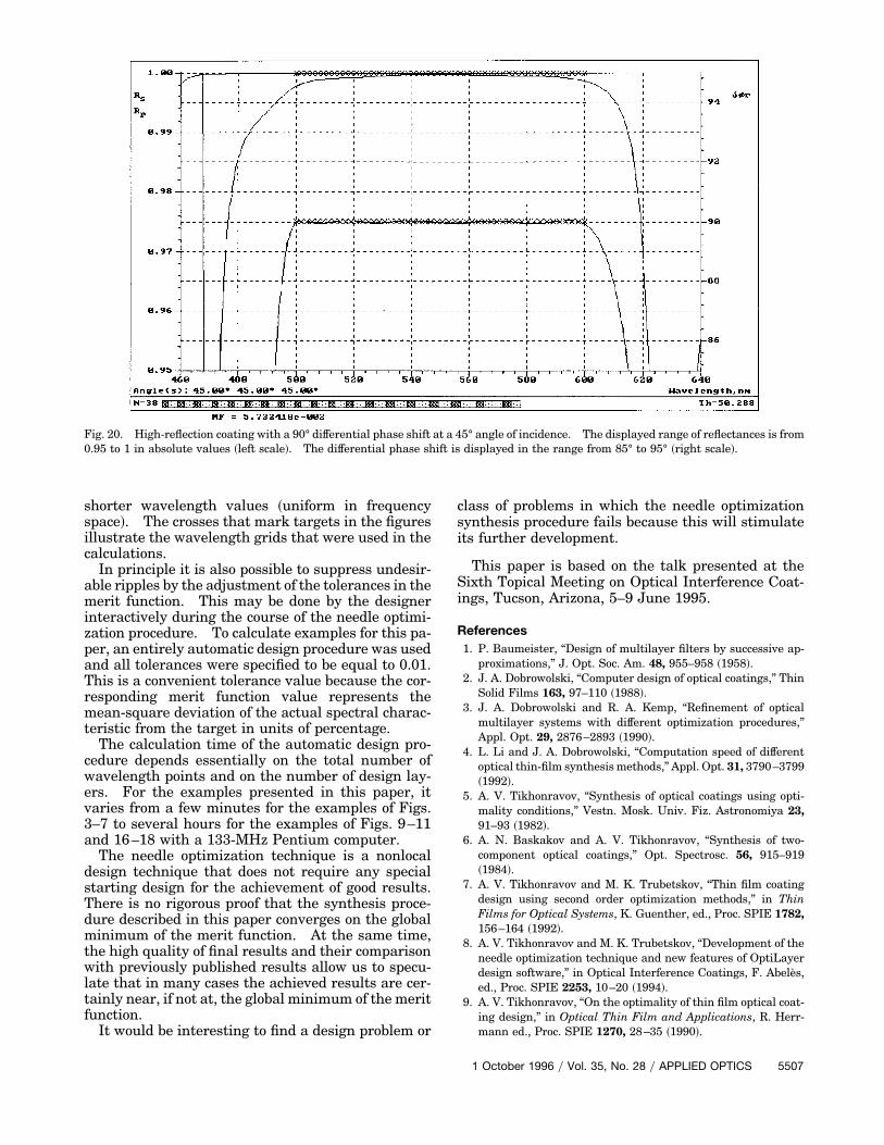
Fig. 20. High-reflection coating with a 90° differential phase shift at a 45° angle of incidence. The displayed range of reflectances is from0.95 to 1 in absolute values ~left scale!. The differential phase shift is displayed in the range from 85° to 95° ~right scale!.
shorter wavelength values ~uniform in frequencyspace!. The crosses that mark targets in the figuresillustrate the wavelength grids that were used in thecalculations.In principle it is also possible to suppress undesir-
able ripples by the adjustment of the tolerances in themerit function. This may be done by the designerinteractively during the course of the needle optimi-zation procedure. To calculate examples for this pa-per, an entirely automatic design procedure was usedand all tolerances were specified to be equal to 0.01.This is a convenient tolerance value because the cor-responding merit function value represents themean-square deviation of the actual spectral charac-teristic from the target in units of percentage.The calculation time of the automatic design pro-
cedure depends essentially on the total number ofwavelength points and on the number of design lay-ers. For the examples presented in this paper, itvaries from a few minutes for the examples of Figs.3–7 to several hours for the examples of Figs. 9–11and 16–18 with a 133-MHz Pentium computer.The needle optimization technique is a nonlocal
design technique that does not require any specialstarting design for the achievement of good results.There is no rigorous proof that the synthesis proce-dure described in this paper converges on the globalminimum of the merit function. At the same time,the high quality of final results and their comparisonwith previously published results allow us to specu-late that in many cases the achieved results are cer-tainly near, if not at, the global minimum of the meritfunction.It would be interesting to find a design problem or
class of problems in which the needle optimizationsynthesis procedure fails because this will stimulateits further development.
This paper is based on the talk presented at theSixth Topical Meeting on Optical Interference Coat-ings, Tucson, Arizona, 5–9 June 1995.
References1. P. Baumeister, “Design of multilayer filters by successive ap-
proximations,” J. Opt. Soc. Am. 48, 955–958 ~1958!.2. J. A. Dobrowolski, “Computer design of optical coatings,” Thin
Solid Films 163, 97–110 ~1988!.3. J. A. Dobrowolski and R. A. Kemp, “Refinement of optical
multilayer systems with different optimization procedures,”Appl. Opt. 29, 2876–2893 ~1990!.
4. L. Li and J. A. Dobrowolski, “Computation speed of differentoptical thin-film synthesis methods,” Appl. Opt. 31, 3790–3799~1992!.
5. A. V. Tikhonravov, “Synthesis of optical coatings using opti-mality conditions,” Vestn. Mosk. Univ. Fiz. Astronomiya 23,91–93 ~1982!.
6. A. N. Baskakov and A. V. Tikhonravov, “Synthesis of two-component optical coatings,” Opt. Spectrosc. 56, 915–919~1984!.
7. A. V. Tikhonravov and M. K. Trubetskov, “Thin film coatingdesign using second order optimization methods,” in ThinFilms for Optical Systems, K. Guenther, ed., Proc. SPIE 1782,156–164 ~1992!.
8. A. V. Tikhonravov and M. K. Trubetskov, “Development of theneedle optimization technique and new features of OptiLayerdesign software,” in Optical Interference Coatings, F. Abeles,ed., Proc. SPIE 2253, 10–20 ~1994!.
9. A. V. Tikhonravov, “On the optimality of thin film optical coat-ing design,” in Optical Thin Film and Applications, R. Herr-mann ed., Proc. SPIE 1270, 28–35 ~1990!.
1 October 1996 y Vol. 35, No. 28 y APPLIED OPTICS 5507

10. A. V. Tikhonravov, “Some theoretical aspects of thin film opticsand their applications,” Appl. Opt. 32, 5417–5426 ~1993!.
11. A. N. Tikhonov Jr., A. V. Tikhonravov, and M. K. Trubetskov,“Second order optimization methods in the synthesis of mul-tilayer coatings,” J. Comput. Math. Math. Phys. 33, 1339–1352 ~1993!.
12. Sh. Furman and A. V. Tikhonravov, Basics of Optics of Mul-tilayer Systems ~Editions Frontieres, Gifsur-Yvette, France,1992!.
13. W. H. Southwell, “Using apodization function to reduce side-lobes in rugate filters,” Appl. Opt. 28, 5091–5094 ~1989!.
14. B. G. Bovard, “Rugate filter design: the modified Fouriertransform technique,” Appl. Opt. 29, 24–30 ~1990!.
15. P. G. Verly and J. A. Dobrowolski, “Iterative correction proce-dure for optical thin film synthesis with the Fourier transformmethod,” Appl. Opt. 29, 3672–3684 ~1990!.
16. H. Fabricius, “Gradient-index filter: designing filters withstep skirts, high reflection, and quintic matching layers,” Appl.Opt. 31, 5191–5196 ~1992!.
17. J. Allen and B. Harrington, “Digitized rugate filters for laserapplication,” in Inhomogeneous andQuasi-Inhomogeneous Op-tical Coatings, J. A. Dobrowolski and P. G. Verly, eds., Proc.SPIE 2046, 126–131 ~1993!.
18. W. E. Johnson and R. L. Crane, “Color neutral rugate filters,”in Inhomogeneous and Quasi-Inhomogeneous Optical Coat-ings, J. A. Dobrowolski and P. G. Verly, eds., Proc. SPIE 2046,132–140 ~1993!.
19. J. B. Adolph, R. W. Bertram, K. L. Yan, P. Zhou, and R. deLeon, “Design and fabrication of multiline inhomogeneous re-jection filters,” in Inhomogeneous and Quasi-Inhomogeneous
5508 APPLIED OPTICS y Vol. 35, No. 28 y 1 October 1996
Optical Coatings, J. A. Dobrowolski and P. G. Verly, eds., Proc.SPIE 2046, 141–146 ~1993!.
20. A. Thelen, “Design of a hot mirror—contest results,” inOpticalInterference Coatings, Vol. 17 of OSA Technical Digest Series~Optical Society of America, Washington, D. C., 1995!, pp.2–10.
21. D. Gray, ed., American Institute of Physics Handbook ~Amer-ican Institute of Physics, New York, 1972!, pp. 6–143.
22. A. G. Sveshnikov, A. V. Tikhonravov and S. A. Yanshin, “Syn-thesis of optical coating at oblique incidence,” Zh. Vychisl. Mat.Mat. Fiz. 23, 929–936 ~1983!.
23. A. Thelen, Design of Optical Interference Coatings, ~McGraw-Hill, New York, 1989!, Chap. 9.
24. V. R. Costich, “Reduction of polarization effects in interferencecoatings,” Appl. Opt. 9, 866–870 ~1970!.
25. A. Thelen, “Nonpolarizing interference filters inside a glasscube,” Appl. Opt. 15, 2983–2985 ~1976!.
26. A. Thelen, “Nonpolarizing edge filters,” J. Opt. Soc. Am. 71,309–314 ~1981!.
27. Z. Knittl and H. Houserkova, “Equivalent layers in obliqueincidence: the problem of unsplit admittance and depolariza-tion of partial reflectors,” Appl. Opt. 21, 2055–2068 ~1982!.
28. C. M. de Sterke, C. J. van der Laan, and H. J. Frankena,“Nonpolarizing beamsplitter design,” Appl. Opt. 23, 595–601~1983!.
29. A. Thelen, “Nonpolarizing edge filters. Part 2,” Appl. Opt. 23,3541–3543 ~1984!.
30. M. Gilo, “Design of nonpolarizing beam splitter inside a glasscube,” Appl. Opt. 31, 5345–5349 ~1992!.