application of the concept of dynamic trim control to
TRANSCRIPT

LOAN COPY: RETURN TO NASA AWL TECHNICAL LIBRARY TP
NRTLAND AFB, M.M. 1512 c .1
NASA Technical Paper 1512
Application of the Concept of Dynamic Trim Control to Automatic Landing of Carrier Aircraft
G. Allan Smith and George Meyer
APRIL 1980
NASA

i TECH LIBRARY KAFB, NM
, _ _ . _ _ - . . 0134732
NASA Technical Paper 1512
Application of the Concept of Dynamic Trim Control to Automatic Landing of Carrier Aircraft
G. Allan Smith and George Meyer Ames Research Ceizter M offett Field, Califorrzia
NASA National Aeronautics and Space Administration
Scientific and Technical Information Office
1980


NOMENCLATURE
smooth-commanded d i r e c t i o n cos ine r o t a t i o n matrix from space axes t o Aasc a i r c r a f t axes
rough-commanded d i r e c t i o n c o s i n e r o t a t i o n ma t r ix from space axes t o a i r c r a f t axes Aasrc
A
A,, measured d i r e c t i o n c o s i n e r o t a t i o n matr ix from space axes t o a i r c r a f t axes
commanded drag c o e f f i c i e n t
commanded drag c o e f f i c i e n t b e f o r e l i m i t i n g
commanded l i f t c o e f f i c i e n t
commanded l i f t c o e f f i c i e n t b e f o r e l i m i t i n g
commanded rolling-moment c o e f f i c i e n t
commanded pitching-moment c o e f f i c i e n t
commanded yawing-moment c o e f f i c i e n t
commanded t h r u s t c o e f f i c i e n t
closed-loop commanded s p e c i f i c f o r c e v e c t o r
cDC
cDC
cLC
cLC
RC
cmC
c"C
cTC
-
-
C
f c c
foc open-loop commanded s p e c i f i c f o r c e vec to r
f t c
q dynamic p r e s s u r e
t o t a l commanded s p e c i f i c f o r c e v e c t o r -
RC smooth-commanded a i r c r a f t p o s i t i o n v e c t o r
R measured a i r c r a f t p o s i t i o n vec to r A
T t i m e from s t a r t of s imula t ion run
smooth-commanded a i r c r a f t v e l o c i t y vec to r
t o t a l commanded a i r c r a f t a c c e l e r a t i o n v e c t o r
vC
t C
A
v measured a i r c r a f t v e l o c i t y vec to r
commanded a n g l e of a t t a c k % r C commanded v e r t i c a l f l i g h t p a t h a n g l e
iii

4 C commanded r o l l ang le
commanded h o r i z o n t a l f l i g h t p a t h ang le
measured a i r c r a f t angular v e l o c i t y v e c t o r
smooth-commanded a i r c r a f t angular v e l o c i t y vec to r
t o t a l commanded a i r c r a f t angular a c c e l e r a t i o n v e c t o r
open-loop commanded a i r c r a f t angular a c c e l e r a t i o n vec to r
closed-loop commanded a i r c r a f t angular a c c e l e r a t i o n vec to r
JIC 6 w
wC
C ci,
l J oc
%c
Acronym
TAFCOS t o t a l a i r c r a f t f l i g h t - c o n t r o l system
i v

APPLICATION OF THE CONCEPT OF DYNAMIC TRIM CONTROL
TO AUTOMATIC LANDING OF CARRIER AIRCRAFT
G. A l l an Smith and George Meyer
Ames Research Center
SUMMARY
The a v a i l a b i l i t y of t h e a i r b o r n e d i g i t a l computer has made p o s s i b l e t h e p r a c t i c a l implementation of t h e concept of a balanced feed-forward and feed- back automatic a i r c r a f t f l i g h t p a t h - c o n t r o l system. The concept i s explained and s imula t ion r e s u l t s are presented. The e s s e n t i a l non l inea r f o r c e and moment c h a r a c t e r i s t i c s of t h e a i r c r a f t are c o l l e c t e d i n t a b u l a r form as dynamic t r i m maps and i n v e r t e d t o g i v e a feed-forward command s i g n a l p a t h which, i n series wi th t h e a c t u a l a i r c r a f t , provides e s s e n t i a l l y a n i d e n t i t y t r a n s f e r func t ion . With p e r f e c t modeling and no d i s t u r b a n c e s t h i s would provide p e r f e c t trajec- t o r y c o n t r o l . Feedback loops are c losed around t h i s l i n e a r p a t h t o compensate f o r d i s tu rbances and imperfect modeling. Simulation r e s u l t s and a f l i g h t test have shown t h a t only a s m a l l f r a c t i o n of t h e t o t a l d r i v e s i g n a l is r equ i r ed from t h e feedback while t h e major p o r t i o n i s provided by t h e feed-forward c o n t r o l .
This concept h a s several advantages. It al lows a s t r a igh t fo rward design f o r a i r c r a f t w i th h igh ly n o n l i n e a r c h a r a c t e r i s t i c s s i n c e convent ional l i n e a r techniques can be employed t o des ign t h e feedback loops around t h e l i n e a r i z e d feed-forward path. The use of t h e complete a i r c r a f t c h a r a c t e r i s t i c s i n t h e feed-forward p a t h al lows a n i n t e g r a t e d des ign s o t h a t t o t a l aerodynamic and p ropu l s ive f o r c e s and moments are combined i n a n a t u r a l way and a i d , r a t h e r than p a r t i a l l y o f f s e t , each o t h e r as o f t e n occurs i n convent ional des igns . The e x p l i c i t a i r c r a f t aerodynamic c h a r a c t e r i s t i c s a v a i l a b l e i n t h e feed-forward s i g n a l p a t h al low d i r e c t l i m i t i n g of commanded a n g l e of a t t a c k and v a r i o u s a c c e l e r a t i o n s and rates s o t h a t a smooth execu tab le t r a j e c t o r y is commanded r e g a r d l e s s of excess ive o r i n a d v e r t e n t commands from an a i r - t r a f f i c - c o n t r o l system o r o t h e r i npu t . Required d i g i t a l computer speed and memory is substan- t i a l l y less than t h a t r equ i r ed f o r convent ional designs of comparable capa- b i l i t y .
Simulation r e s u l t s are p resen ted f o r an a p p l i c a t i o n t o automatic landing on an a i r c r a f t carrier.
INTRODUCTION
Precise f l i g h t p a t h c o n t r o l i s r equ i r ed over t h e approach t r a j e c t o r y t o land an a i r c r a f t on an a i r c r a f t carrier i n heavy seas. r e s t r i c t e d t o a small area on a deck t h a t is p i t c h i n g and heaving due t o wave a c t i o n . Furthermore, t h e f l i g h t p a t h i s c o n t i n u a l l y d i s t u r b e d by severe atmo- s p h e r i c t u rbu lence generated i n p a r t by t h e carrier s u p e r s t r u c t u r e .
The touchdown p o i n t i s
Landing

t h e a i r c r a f t is p a r t i c u l a r l y d i f f i c u l t a t n i g h t and is g e n e r a l l y acknowledged t o b e t h e most d i f f i c u l t p i l o t i n g t a s k encountered i n r o u t i n e ope ra t ions .
I n an a t t empt t o improve l and ing performance, t h e Navy h a s developed an automatic ca r r i e r - l and ing system. The system i s based on a convent ional auto- p i l o t t h a t i s c o n t r o l l e d by a t t i t u d e s i g n a l s sent by r a d i o l i n k from t h e car- rier and generated from p a t h e r r o r s determined by a ca r r i e r -based r a d a r . Although t h e system i s o p e r a t i o n a l f o r a few types of a i r c r a f t , i t has pe r fo r - mance d e f i c i e n c i e s i n s t r o n g tu rbu lence and s i g n i f i c a n t touchdown p o i n t d i s - pers ion. The a l t e r n a t i v e automatic-control-system des ign concept p re sen ted i n t h i s r e p o r t has shown p o t e n t i a l f o r improving l and ing performance.
This new des ign concept w a s developed a t Ames Research Center over t h e p a s t 4 years . The t h e o r e t i c a l b a s i s f o r t h e system is p resen ted i n r e f e r - ence 1. concept t o t h e c a r r i e r - l a n d i n g problem and p r e s e n t r e s u l t s of szmulation s t u d i e s of an automatic ca r r i e r - l and ing system based on t h e new p r i n c i p l e s .
This r e p o r t w i l l e x p l a i n t h e system s t r u c t u r e developed t o apply t h e
The concept provides f o r c o n t r o l of t h e a i r c r a f t t r a j e c t o r y d i r e c t l y by commanding t h e aerodynamic and p ropu l s ive f o r c e s r e q u i r e d r a t h e r t han by a con- v e n t i o n a l a u t o p i l o t t h a t commands a i r c r a f t a t t i t u d e t o minimize t r a j e c t o r y e r r o r s . I n a d d i t i o n , t h e dynamic t r i m concept a l lows a s i n g l e c o n f i g u r a t i o n t o f u n c t i o n over t h e complete f l i g h t envelope without t h e ga in schedul ing o r c o n f i g u r a t i o n switching t h a t is used i n convent ional systems based on p e r t u r - b a t i o n s about a number of d i f f e r e n t s t a t i c t r i m p o i n t s . The concept i s termed a " t o t a l a i r c r a f t f l i g h t - c o n t r o l system," o r TAFCOS. TAFCOS is e s s e n t i a l l y an open-loop, feed-forward system t h a t commands t h e proper in s t an taneous t h r u s t , ang le of a t t a c k , and r o l l ang le dynamic t r i m cond i t ions t o achieve t h e f o r c e s r equ i r ed t o fol low t h e d e s i r e d t r a j e c t o r y . The dynamic t r i m cond i t ions are determined by an i n v e r s i o n of t h e a i r c r a f t non l inea r f o r c e c h a r a c t e r i s t i c s t o c a l c u l a t e t h e r equ i r ed ang le of a t t a c k and t h r o t t l e s e t t i n g , wh i l e t h e com- manded r o l l ang le i s determined from t h e r e q u i r e d normal and l a t e r a l f o r c e c o e f f i c i e n t s . The ang le of a t t a c k i s combined wi th r o l l ang le and f l i g h t p a t h ang le s t o give t h e commanded a t t i t u d e . This feed-forward design i s completed by i n v e r s i o n of t h e a i r c r a f t non l inea r moment c h a r a c t e r i s t i c s t o determine t h e c o n t r o l s u r f a c e angles .
The concept of open-loop c o n t r o l f o r a completely c a l i b r a t e d system can provide any d e s i r e d response t h a t is w i t h i n t h e p h y s i c a l c a p a b i l i t y of t h e system. On t h e o t h e r hand, t h e va lue of feedback t o d e a l w i t h u n c a l i b r a t e d systems o r systems wi th u n c e r t a i n t i e s and d i s tu rbances is w e l l e s t a b l i s h e d . Therefore t h e b a s i c open-loop design of TAFCOS is supplemented by feedback loops t h a t compensate f o r l a c k of knowledge of t h e a i r c r a f t c h a r a c t e r i s t i c s and f o r imperfect wind e s t ima t ion , and provide c o n t r o l i n t h e presence of d i s - turbances. w i th as much a p r i o r i information as f e a s i b l e about t h e a i r c r a f t f o r c e and moment c h a r a c t e r i s t i c s ; i t uses feedback t o provide t i g h t c o n t r o l i n t h e face of l i m i t e d knowledge of p l a n t c h a r a c t e r i s t i c s , measurement inaccurac i e s , and d i s tu rbance inpu t s .
TAFCOS is a balanced system t h a t employs an open-loop c o n t r o l l e r
Advances i n a v i o n i c s technology have produced a i r b o r n e d i g i t a l computers of t h e type needed t o c a r r y ou t t h e c a l c u l a t i o n s r e q u i r e d f o r TAFCOS.
2

Extensive two-dimensional t a b l e s of t h e a i r c r a f t f o r c e and moment characteris- t i c s are used f o r t h e i n v e r s i o n c a l c u l a t i o n s , and numerous ma t r ix mul t ip l i ca - t i o n s are requ i r ed t o t ransform t h e f o r c e and moment v e c t o r s between v a r i o u s coord ina te systems. Computational f e a s i b i l i t y of t h e concept has r e c e n t l y been demonstrated by a s u c c e s s f u l f l i g h t test of TAFCOS i n a STOL a i r c r a f t ( r e f . 2 ) . A Sperry 1819A a i r b o r n e d i g i t a l computer w a s used. Only a small p o r t i o n of t h e computer c a p a c i t y w a s r equ i r ed .
During t h e p a s t 3 y e a r s several s imula t ions of t h e c u r r e n t o p e r a t i o n a l Navy automatic c a r r i e r - l a n d i n g system have been c a r r i e d ou t on t h e p i l o t e d s imula to r s a t Ames Research Center. Research Center, t h e Naval A i r T e s t Center, and t h e Naval A i r Development Center t o i n v e s t i g a t e p i l o t acceptance of va r ious system modi f i ca t ions de- signed t o improve touchdown p o i n t d i s p e r s i o n under t u r b u l e n t cond i t ions ( r e f . 3) . Navy f o r t h e s e s imula t ions w a s used t o r ep resen t t h e a i r c r a f t i n t h e TAFCOS s imula t ions t h a t are t h e s u b j e c t of t h i s r e p o r t . The model i nc ludes t h e non- l i n e a r aerodynamic f o r c e and moment equat ions and non l inea r e f f e c t s of t h e engine, i nc lud ing h y s t e r e s i s i n t h e t h r o t t l e a c t u a t o r .
They w e r e conducted j o i n t l y by Ames
The s a m e computer s imula t ion model of t h e A-7E a i r c r a f t used by t h e
The s imula t ions presented h e r e w e r e c a r r i e d o u t t o demonstrate t h a t t h e TAFCOS concept provides s u b s t a n t i a l l y improved performance f o r t h e carrier landing task. The r e s u l t s are presented i n f o u r s e c t i o n s t o show t h e c r i t i c a l responses t h a t must be examined t o e v a l u a t e automatic control-system perfor- mance. The f i r s t r e s u l t s show a l l t h e important v a r i a b l e s f o r a t ip-over and landing maneuver without atmospheric turbulence. This a l lows t h e a t t i t u d e and t h r u s t c o n t r o l i n t e r a c t i o n t o be c l e a r l y observed and e s t a b l i s h e s a perfor- mance r e fe rence f o r t h e t a s k of t r a c k i n g t h e moving deck. The next r e s u l t s show t h e performance f o r a l and ing wi th atmospheric turbulence.
The q u a l i t y of an automatic c o n t r o l system is e s t a b l i s h e d by both i t s a b i l i t y t o r e g u l a t e t o a r e f e r e n c e f l i g h t p a t h i n t h e presence of i npu t d i s t u r - bances and t o respond t o maneuver commands. Therefore, t h e f i n a l two s e c t i o n s of r e s u l t s show t h e system response t o a series of s e v e r e g u s t i n p u t s and response t o a sequence of maneuver commands t h a t i nc lude a l t i t u d e changes and la te ra l f l i g h t p a t h c o n t r o l .
AUTOMATIC CARRIER-LANDING TASK
The automatic c a r r i e r - l a n d i n g s i t u a t i o n is i l l u s t r a t e d i n f i g u r e 1. The carrier normally heads i n t o t h e wind a t a speed such t h a t t h e r e l a t i v e wind i s p a r a l l e l t o t h e deck a t about 30 knots . The a i r c r a f t is f i r s t d i r e c t e d t o a marshal1 p o i n t o r t o a ho ld ing p a t t e r n . Ind iv idua l a i r c r a f t are then c l e a r e d t o t h e approach course a t 2-min i n t e r v a l s . For t h e A-7E a i r c r a f t considered i n t h i s s imula t ion s tudy , t h e a i r c r a f t is commanded t o hold a s t eady v e l o c i t y , w i th r e s p e c t t o t h e wind of 129 kno t s , which is 99 kno t s w i t h r e s p e c t t o t h e carrier.
For t h i s s imula t ion a level-approach course is commanded a t an e l e v a t i o n of 152.4 m (500 f t ) above t h e ca r r i e r -deck r e f e r e n c e u n t i l a 3.5" g l i d e s l o p e
3

t o t h e i d e a l touchdown p o i n t is i n t e r c e p t e d . The i d e a l touchdown p o i n t is l o c a t e d 70 m (230 f t ) a f t of t h e carrier c e n t e r of p i t c h . The a i r c r a f t must touch down w i t h i n 218.3 m ( t 6 0 f t ) l o n g i t u d i n a l l y and k4.6 m (515 f t ) l a t e r a l l y of t h a t p o i n t .
The carrier is equipped w i t h a t r a c k i n g r a d a r t h a t determines t h e air- c r a f t p o s i t i o n w i t h r e s p e c t t o t h e carrier. A shipboard iner t ia l p l a t fo rm measures t h e in s t an taneous e l e v a t i o n of t h e i d e a l touchdown p o i n t due t o deck p i t c h and heave w i t h r e s p e c t t o t h e undis turbed carrier deck r e f e r e n c e posi- t i o n . As shown i n f i g u r e 1, a f t e r t ip-over , t h e a i r c r a f t is commanded t o descend on t h e g l i d e s l o p e u n t i l 12 sec b e f o r e touchdown. A t t h a t t i m e t h e a i r c r a f t is commanded t o fo l low t h e in s t an taneous d i sp laced p o s i t i o n of t h e touchdown p o i n t .
An approach t h a t misses t h e r equ i r ed touchdown area o r an a r r e s t i n g w i r e i s termed a b o l t e r and t h e a i rc raf t i s commanded t o fo l low a recovery p a t h back t o t h e r e f e r e n c e a l t i t u d e of 152.4 m (500 f t ) b e f o r e making another a t tempt .
The most c r i t i c a l p o r t i o n of t h e l and ing sequence is t h e f i n a l 12 sec, du r ing which t i m e t h e a i r c r a f t is commanded t o fo l low t h e in s t an taneous verti- cal p o s i t i o n of t h e touchdown p o i n t . For t h i s s imula t ion , t h e deck motion w a s taken as t h e sum of two s i n u s o i d a l displacements due t o heave and p i t c h , t h e former a t a frequency of 0 .1 Hz and an amplitude of t 1 .2 m ( t 4 f t ) , and t h e l a t t e r a t a frequency of 0.096 Hz and an amplitude of +lo, which is k1.2 m (54 f t ) ver t ica l displacement a t t h e 70.1-m (230-ft) d i s t a n c e from t h e c e n t e r of p i t c h . This can produce a m a x i m u m touchdown p o i n t excursion of 52.4 m (+8 f t ) . Also, du r ing t h e f i n a l p o r t i o n of t h e r u n , s t r o n g atmospheric turbu- l ence , c a l l e d bu rb le , is encountered i n t h e carrier wake. This t u rbu lence is caused by t h e i n t e r a c t i o n o f t h e carrier s u p e r s t r u c t u r e wi th t h e wind; i t w a s modeled as a cornbination of ver t ical and h o r i z o n t a l g u s t p a t t e r n s i n t i m e and space as a f u n c t i o n of carrier deck a t t i t u d e p l u s random superimposed turbu- l ence . Peak t o t a l t u rbu lence w a s about t1.8 m / s e c (k6 f t / s e c ) .
The primary concern i n t h i s s imula t ion w a s t o i n v e s t i g a t e a i r c r a f t landing-point d i s p e r s i o n due t o t h e e f f e c t s of p i t c h and heave deck motion and atmospheric turbulence. Therefore, 160 l and ing s imula t ion runs w e r e made wi th v a r i o u s random turbulence p a t t e r n s and w i t h d i f f e r e n t deck motion component phases a t touchdown.
It should be noted t h a t a carrier l and ing is accomplished by f l y i n g a d i r e c t p a t h t o t h e deck without any l and ing f l a r e .
For t h e c u r r e n t l y o p e r a t i o n a l Navy automatic c a r r i e r - l a n d i n g system t h e a i r c r a f t i s under manual c o n t r o l during a ho ld ing p a t t e r n , o r a f t e r a missed approach during wave-off. However, TAFCOS h a s t h e p o t e n t i a l f o r automatic c o n t r o l du r ing such s i t u a t i o n s , so s imula t ion runs w e r e made of a d d i t i o n a l tra- j e c t o r i e s t h a t i nco rpora t ed lateral maneuvers, a l t i t u d e changes, and seve re g u s t s . These runs included maneuver commands and d i s t u r b a n c e s t h a t i l l u s t r a t e t h e system response over a much wider f l i g h t envelope than t h e convent ional carrier approach pa th .
4

An important p a r t o f any automatic t r a j e c t o r y - c o n t r o l system i s t h e in s t rumen ta t ion r equ i r ed t o measure t h e a i r c r a f t p o s i t i o n wi th r e s p e c t t o t h e commanded t r a j e c t o r y . The c u r r e n t Navy system uses a ship-mounted t r a c k i n g r a d a r i n conjunct ion wi th a beacon t ransponder on t h e a i r c r a f t . Such a system w a s t h e r e f o r e s imulated f o r TAFCOS; i t included t h e usua l l o s s of r a d a r i n f o r - mation when t h e a i r c r a f t i s w i t h i n about 150 m (492 f t ) of touchdown. Of course, TAFCOS r e c e i v e s t h e r a d a r p o s i t i o n information by d a t a l i n k from t h e carrier and p rocesses i t i n t h e a i r b o r n e d i g i t a l computer. This is i n con- trast t o t h e o p e r a t i o n a l system, which processes t h e r a d a r d a t a i n a shipborne computer and sends a i r c r a f t a t t i t u d e commands t o t h e approaching v e h i c l e . The r a d a r p o s i t i o n and t h e v e l o c i t y and a c c e l e r a t i o n d a t a used by TAFCOS w e r e cor- rupted by a p p r o p r i a t e n o i s e i n p u t s .
AUTOMATIC CONTROL SYSTEM
The command s t r u c t u r e of TAFCOS is e n t i r e l y d i f f e r e n t from t h a t of a con- v e n t i o n a l c o n t r o l system. It employs dynamic t r i m maps which r e p r e s e n t an i n v e r s i o n of t h e non l inea r six-degree-of-freedom equa t ions of t h e a i r c r a f t . The t r i m maps t a k e t h e form of e x t e n s i v e two-dimensional t a b l e s of f o r c e and moment d a t a . They r e p r e s e n t a c a l i b r a t i o n of t h e a i r c r a f t so t h a t t r a j e c t o r y commands can be processed i n an open-loop f a s h i o n t o y i e l d s u r f a c e and t h r u s t c o n t r o l s . Closed-loop s ta te feedback i s employed t o balance t r i m map inaccu- racies and measurement u n c e r t a i n t i e s .
Figures 2 and 3 w i l l b e used t o d e s c r i b e t h e c o n f i g u r a t i o n and f u n c t i o n s of TAFCOS. Tkiey i l l u s t r a t e t h e s i g n a l f low p a t h s t h a t w i l l be t r a c e d to show what o p e r a t i o n s are c a r r i e d o u t by t h e system. The d e t a i l s of how t h e s e opera- t i o n s are accomplished are presented i n appendix A. Many of t h e q u a n t i t i e s i n f i g u r e s 2 and 3 are v e c t o r s which, f o r c a l c u l a t i o n , are re so lved i n t o compo- n e n t s i n a p p r o p r i a t e coord ina te systems. For example, t h e t r a j e c t o r y is pre- s en ted i n an i n e r t i a l frame, t h e major aerodynamic f o r c e s act i n a frame determined by t h e a i r c r a f t v e l o c i t y w i t h r e s p e c t t o t h e a i r mass, and t h e air- c r a f t c o n t r o l s u r f a c e s and engine t h r u s t are expressed i n an a i r c r a f t body r e f e r e n c e frame. Therefore, a c h a r a c t e r i s t i c of TAFCOS is t h e repeated reso- l u t i o n of f o r c e s , moments, a c c e l e r a t i o n s , v e l o c i t i e s , and p o s i t i o n s from one r e f e r e n c e frame t o another u s ing m a t r i x t r ans fo rma t ion methods. F igu re 2 i l l u s t r a t e s only t h e open-loop elements and does n o t i nc lude t h e closed-loop feedback employed i n t h e complete system. Figure 2 w i l l be used €o r a b r i e f exp lana t ion of t h e fundamental concept of TAFCOS without c o n s i d e r a t i o n of many secondary, a l though important , d e t a i l s t h a t are t r e a t e d more completely i n t h e d i s c u s s i o n of f i g u r e 3 and i n appendix A.
The d e s i r e d t r a j e c t o r y i n f i g u r e 2 e n t e r s t h e system as a series of s t r a i g h t , c i r c u l a r , o r h e l i c a l arc geometric segments desc r ibed by t h e i r l e n g t h , o r i e n t a t i o n , and a i r speed . Angles of climb o r descent f o r a l l seg- ments, r a d i i , and arc l e n g t h s f o r c i r c u l a r and h e l i c a l s e c t i o n s are given. From t h i s geometric-data i n p u t t h e t r a j e c t o r y command sequencer produces a c o n s i s t e n t commanded dynamic sequence of t r a j e c t o r y p o s i t i o n , v e l o c i t y , and a c c e l e r a t i o n v e c t o r s i n i n e r t i a l space coord ina te s . These dynamic commands
5

are rough i n t h e sense t h a t t hey may r e q u i r e in s t an taneous changes i n v e l o c i t y , d i r e c t i o n , and, sometimes, p o s i t i o n a t t h e segment j u n c t i o n s . The t r a j e c t o r y i s de f ined i n space re la t ive t o t h e carrier and a t a commanded a i r s p e e d .
The t r a j e c t o r y command gene ra to r smooths and l i m i t s t h e s e rough commands t o ' b e c o n s i s t e n t w i th t h e d e s i r e d a i r c r a f t response. gene ra to r a l s o performs a coord ina te system r o t a t i o n so t h a t t h e d e s i r e d tra- j e c t o r y commands i n i n e r t i a l space axes are transformed t o re la t ive wind veloc- i t y axes. The output v e c t o r 0, i s a smooth execu tab le commanded accelera- t i o n . wind t o c a l c u l a t e commanded f l i g h t p a t h ang le s , rC and $c.
The t r a j e c t o r y command
Smooth-commanded v e l o c i t y components are combined wi th est imated s t eady
I n t h e c o e f f i c i e n t development s e c t i o n , gc is m u l t i p l i e d by a i r c r a f t m a s s t o g ive t h e f o r c e r equ i r ed t o c a r r y ou t t h e d e s i r e d t r a j e c t o r y . The f o r c e is then divided by dynamic p r e s s u r e and wing area t o g i v e t h e t o t a l l i f t and drag c o e f f i c i e n t s . These t o t a l commanded c o e f f i c i e n t s , which inc lude engine t h r u s t f o r c e s as w e l l as aerodynamic f o r c e s , are s e n t t o t h e f o r c e t r i m map. Furthermore, t h e r a t i o of t h e la teral t o t h e normal commanded f o r c e c o e f f i - c i e n t g ives t h e tangent of t h e commanded r o l l a n g l e cal r e p r e s e n t a t i o n of t h e f o r c e t r i m map which is seen t o be a series of l i f t d rag p o l a r s f o r t h e a i r c r a f t , s h i f t e d by the e f f e c t of e n g h e t h r u s t as ind i - ca t ed by t h e t h r u s t c o e f f i c i e n t l i f t and d rag c o e f f i c i e n t s C L ~ and C D ~ . The t r i m map ou tpu t s are t h e corre-
ca l cu la - sponding commanded ang le of a t t a c k ac and t h r u s t c o e f f i c i e n t ted by t h e d i g i t a l computer; which c a r r i e s o u t an i n t e r p o l a t i o n of t h e t r i m - m a p d a t a s t o r e d i n t a b u l a r form. This i s a dynamic t r i m map i n t h e sense t h a t a n g l e of a t t a c k and t h r u s t are c a l c u l a t e d f o r any v e c t o r a c c e l e r a t i o n , n o t j u s t f o r a convent ional trimmed f l i g h t p a t h . A very convenient f e a t u r e of t h e t r i m map i s t h e ease w i t h which i t al lows commands t o b e l i m i t e d t o s e l e c t e d va lues of ac and CT-. l i m i t e d t o between -2" and +16" and commanded t h r u s t c o e f f i c i e n t t o between 0.01 and 0.7. This p e r m i t s commands over almost t h e e n t i r e f l i g h t envelope bu t prevents commands t h a t approach s t a l l cond i t ions . The e f f e c t of t h i s l i m i t i n g i s c l e a r l y seen i n f i g u r e 8 (e ) of t h e r e s u l t s .
c $ ~ . Figure 4 i s a graphi-
CT,. I n p u t s t o t h e t r i m map are t h e commanded
cTC
For t h i s s imula t ion , commanded ang le of a t t a c k w a s
I n f i g u r e 2 , one ou tpu t of t h e t r i m map, commanded t h r u s t c o e f f i c i e n t , CT,, is converted t o commanded t h r u s t and s e n t t o an engine t h r u s t t a b l e where t h e d i g i t a l computer performs an i n v e r s e i n t e r p o l a t i o n t o c a l c u l a t e t h e com- manded t h r o t t l e angle . The o t h e r output of t h e t r i m map, commanded ang le of a t t a c k f l i g h t p a t h a n g l e s t o g i v e t h e commanded a i r c r a f t a t t i t u d e .
ac, i s combined wi th commanded r o l l a n g l e and h o r i z o n t a l and v e r t i c a l
A procedure g e n e r a l l y s i m i l a r t o t h a t followed i n t h e t r a j e c t o r y p o r t i o n of t h e system is then employed i n t h e a t t i t u d e c o n t r o l s e c t i o n . The a t t i t u d e command gene ra to r provides a smooth execu tab le angu la r a c c e l e r a t i o n v e c t o r com- mand G C . i n e r t i a ma t r ix t o g i v e t h e torques r equ i r ed t o c a r r y o u t t h e des i r ed a t t i t u d e v a r i a t i o n s . These to rques are then expressed i n t e r m s of moment c o e f f i c i e n t s . The moment t r i m map i n f i g u r e 2 i n v e r t s t h e a i r c r a f t torque equat ions t o y i e l d t h e c o n t r o l s u r f a c e ang le s needed t o gene ra t e t h e commanded angular accelera- t i o n v e c t o r .
This angular a c c e l e r a t i o n v e c t o r is m u l t i p l i e d by t h e a i r c r a f t
6

When t h e b a s i c feed-forward c o n t r o l of f i g u r e 2 i s implemented w i t h rea- Gonably a c c u r a t e t r i m maps, t h e a i r c r a f t fo l lows t h e commanded a c c e l e r a t i o n V, q u i t e w e l l . t h e inpu t command. command system and l i n e a r theory can be used t o select t h e feedback ga ins used f o r t h e a c t u a l complete c o n t r o l system ( r e f . 4 ) .
The ou tpu t response i s e s s e n t i a l l y l i n e a r l y p r o p o r t i o n a l t o Thus, it can b e considered t o b e a l i n e a r a c c e l e r a t i o n
The b a s i c open-loop concept of f i g u r e 2 is augmented i n t h e complete TAFCOS c o n f i g u r a t i o n by !he a d d i t i o n of feedback loops as shown i n f i g u r e 3 . Figure 3 shows t h e unde r ly ing s t r u c t u r e of f i g u r e 2 w i t h a d d i t i o n a l symbolism as w e l l as t h e closed-loop p o s i t i o n and a t t i t u d e feedback. Only t h e new addi- t i o n s and c e r t a i n d e t a i l s p rev ious ly ignored w i l l b e discussed i n crjnnection w i t h f i g u r e 3 .
The commanded a c c e l e r a t i o n qC i n f i g u r e 2 j-ncludes a component t o ba l - ance t h e a c c e l e r a t i o n of g r a v i t y so it is more a c c u r a t e l y a s p e c i f i c f o r c e o r t h e t o t a l f o r c e p e r u n i t m a s s r equ i r ed t o fo l low t h e t r a j e c t o r y under t h e i n f l u e n c e of g r a v i t y . The symbol f t c i s t h e r e f o r e introduced t o i n d i c a t e commanded s p e c i f i c f o r c e i n f i g u r e 3 .
I n t h e t r a j e c t o r y r e g u l a t o r of f i g u z e 3 t h e smooth commanded p o s i t i o n Rc i s compared w i t h t h e measured p o s i t i o n R and t h e smooth commanded v e l o c i t y Vc i s compared w i t h t h e measured v e l o c i t y $. The r e s u l t i n g e r r o r s i g n a l s are combined w i t h a p p r o p r i a t e g a i n s and l i m i t s t o g ive a closed-loop s p e c i f i c f o r c e command fcc. This p e r t u r b a t i o n command from t h e t r a j e c t o r y r e g u l a t o r is added t o t h e open-loop command t o form t h e t o t a l s p e c i f i c f o r c e com- nand f t c . For most maneuvers, f cc 1 s only about 20% of foc. This means t h a t t h e major burden of c o n t r o l i s borne by t h e open loop.
fo,
The t r a j e c t o r y comnand generator and t h e t r a j e c t o r y r e g u l a t o r are t h e p r i n c i p a l p a r t s of t h e system where ga in and l i m i t adjustments are made t o achieve s a t i s f a c t o r y performance, which i s c h a r a c t e r i z e d by smooth and a c c u r a t e response t o t r a j e c t o r y commands, p rope r ly coordinated and s u i t a b l y l i m i t e d con t ro l - su r face and engine- thrust responses t o d i s tu rbance i n p u t s , and w e l l - executed c a p t u r e of t h e i n i t i a l t r a j e c t o r y and t r a n s i t i o n between t r a j e c t o r y segments.
A s p rev ious ly noted, t h e f o r c e t r i m map f o r t h i s a p p l i c a t i o n expres ses t h e l i f t and drag c o e f f i c i e n t s as f u n c t i o n s of ang le of a t t a c k and t h r u s t . For a d i f f e r e n t a p p l i c a t i o n , a three-dimensional trim map w a s developed w i t h f l a p ang le as a t h i r d parameter and a three-parameter i n t e r p o l a t i o n r o u t i n e w a s used i n t h e a i r b o r n e d i g i t a l computer ( r e f . 5 ) . For a t t i t u d e commands, TAFCOS manipulates a n g l e s by c o n s t r u c t i n g t h e corresponding d i r e c t i o n c o s i n e matrices t h a t r e p r e s e n t t h e angular r o t a t i o n about t h e a p p r o p r i a t e a x i s ( r e f . 6 ) . The r e q u i r e d ang le of a t t a c k aC and r o l l ang le O c are combined wi th commanded f l i g h t p a t h ang le s matrices t o g ive t h e rough commanded a i r c r a f t a t t i t u d e m a t r i x serves as t h e inpu t t o t h e a t t i t u d e command gene ra to r . The a t t i t u d e command gene ra to r provides a smooth commanded a t t i t u d e matrix Aasc, a smooth commanded angu la r v e l o c i t y v e c t o r w c , and a smooth commanded open-loop angu la r accelera- t i o n v e c t o r ioc.
rc and +c by m u l t i p l i c a t i o n of t h e i r d i r e c t i o n c o s i n e A a s r c which
The a t t i t u d e r e g u l a t o r compares t h e commanded and measured
7

a t t i t u d e s and angu la r v e l o c i t i e s t o form e r r o r s i g n a l s which are combined wi th s u i t a b l e ga ins and l i m i t s t o g i v e a closed-loop p e r t u r b a t i o n angu la r acce le ra - t i o n command ice. This is added t o t h e open-loop command hoc t o g i v e t h e t o t a l angu la r a c c e l e r a t i o n command vectcr Ljc.
The moment t r i m map i n f i g u r e 3 is f u n c t i o n a l l y s i m i l a r t o t h e f o r c e trim map. It accep t s commanded moment c o e f f i c i e n t s as i n p u t s and provides t h e com- manded c o n t r o l s u r f a c e p o s i t i o n s necessa ry t o ach ieve t h e corresponding angu la r a c c e l e r a t i o n s . These commanded s u r f a c e d e f l e c t i o n s are t h e f i n a l ou tpu t of t h e a i r b o r n e d i g i t a l computer. s e rvos which produce t h e a c t u a l d e f l e c t i o n s as in f luenced by se rvo l a g s and by s u r f a c e rate and d e f l e c t i o n l i m i t s . Add i t iona l d e t a i l s of t h e TAFCOS s t r u c t u r e are discussed i n appendix A i n connection wi th f i g u r e 10 which is a f u r t h e r expansion of f i g u r e 3.
They are sent t o convent ional con t ro l - su r face
I n summary, TAFCOS i s an aerodynamically o r i e n t e d computational f l i g h t c o n t r o l system t h a t f u l l y inco rpora t e s t h e l i m i t a t i o n s and n o n l i n e a r i t i e s of t h e f o r c e and moment c h a r a c t e r i s t i c s , i nc lud ing t h e p ropu l s ion system, so t h a t it is p o s s i b l e t o maintain d e s i r e d s ta l l margins and l i m i t s on a t t i t u d e response rates and c o n t r o l d e f l e c t i o n s , and y e t e x p l o i t t h e a i r c r a f t c a p a b i l i - t ies over i t s f u l l p r a c t i c a l f l i g h t envelope.
SIMULATION RESULTS
Simulation runs w e r e c a r r i e d . out on a g e n e r a l purpose d i g i t a l computer (IBM 360/67). a b l e s as measured du r ing t h e approach t o t h e carrier. Measurements are taken i n a right-handed o r thogona l coord ina te system wi th o r i g i n a t t h e undis turbed c e n t e r of p i t c h of t h e carrier. The carrier is on a s t r a i g h t cour se w i t h a 30-knot wind over t h e deck which is a l igned w i t h t h e X a x i s of t h e i n e r t i a l space coord ina te system as def ined i n appendix B. The carrier heave and p i t c h motions are t h e s a m e as those used f o r t h e Navy s imula t ions mentioned previ- ous ly ; s i n u s o i d a l heave and p i t c h t h a t produce a maximum vert ical excursion of t h e touchdown po in t of about k 2 . 4 m (+8 f t ) .
The r e s u l t s appear as t ime-his tory p l o t s of s i g n i f i c a n t vari-
The r e s u l t s are arranged i n f o u r groups. u r e s 5(a-h) which show r e s u l t s f o r a t ip-over and landing wi th c a r r i e r deck motion b u t no atmospheric t u rbu lence o r o t h e r d i s tu rbances . This p o r t r a y s t h e upper bound of performance level, a l lows a comparison of smooth v a r i a b l e s , and i l l u s t r a t e s t h e o r e t i c a l design cons ide ra t ions .
The f i rs t group inc ludes f i g -
The second group inc ludes f i g u r e s 6(a-f) and 7 which show r e s u l t s f o r a t ip-over and landing wi th c a r r i e r deck motion fol lowing, atmospheric turbulence, r a d a r noise , and t h r o t t l e h y s t e r e s i s t o g i v e a real is t ic s imula t ion . One hun- dred and s i x t y of t h e s e runs wi th d i f f e r e n t d i s tu rbance s t a t i s t i c s w e r e made t o c o l l e c t d a t a on touchdown d i s p e r s i o n . R e s u l t s from a t y p i c a l run are pre- s en ted i n t h e f i g u r e s .
8

The t h i r d group i n c l u d e s f i g u r e s 8(a-f) which show r e s u l t s f o r a s t r a i g h t and level run w i t h no atmospheric tu rbulence b u t w i t h a series of sharp , severe g u s t s t o show how TAFCOS responds t o d i s tu rbance i n p u t s .
The f o u r t h group i n c l u d e s f i g u r e s 9(a-f) which show results f o r a modi- f i e d racetrack course w i t h l a r g e a l t i t u d e changes. tu rbulence , bu t a s t eady 30-knot wind is iniposed. These curves show how TAFCOS responds t o a range of l a t e ra l and ver t ica l commands a t a commanded a i r speed of 129 kno t s f o r a va ry ing wind o r i e n t a t i o n t o t h e f l i g h t p a t h .
There i s no atmospheric
Carrier Approach w i t h N o Dis turbances
The performance of the A-7E a i r c r a f t w i t h the TAFCOS automatic carrier landing system f o r a s i m p l i f i e d s t anda rd touchdown run w i t h no atmospheric t u r - bulence i s shown i n f i g u r e s 5(a-h). For f i g u r e s 5(a-e) , no h y s t e r e s i s i s inc luded i n t h e t h r o t t l e a c t u a t o r , and radar-range informat ion is used a l l t h e way t o touchdown. Moreover, t h e phase of t h e carr ier s i n u s o i d a l deck motion i s such t h a t t h e touchdown occurs a t t h e peak of touchdown p o i n t d i s - placement from i t s undis turbed p o s i t i o n . These runs t h u s e s t a b l i s h t h e b e s t system performance; t hey w i l l b e compared wi th o t h e r runs t h a t i nc lude more r e a l i s t i c ope ra t ing cond i t ions . The a i r c r a f t i s moving i n t h e d i r e c t i o n of t h e p o s i t i v e X and Z axes toward t h e c a r r i e r a t t h e o r i g i n . Thus t h e a i r - c r a f t p o s i t i o n coord ina te s are g e n e r a l l y nega t ive i n both t h e X and Z axes .
Figure 5 ( a ) c o n s i s t s of t i m e h i s t o r i e s of t h e t r a j e c t o r y v a r i a b l e s i n t h e ver t ica l channel. Tip-over occurs a t 8 sec where t h e a c t u a l ver t ica l p o s i t i o n and v e l o c i t y show a ve ry smooth t r a n s i t i o n . To provide a n t i c i p a t i o n , t h e rough p o s i t i o n and v e l o c i t y commands jump from t h e l e v e l - f l i g h t t r a j e c t o r y t o a g l i d e s l o p e of 3.5". A s e c t i o n of t h e i n i t i a l v e r t i c a l - p o s i t i o n curves , p l o t t e d t o expanded t i m e and a l t i t u d e scales, i s presented t o show how e f f e c t i v e l y t h e t r a j e c t o r y command gene ra to r smooths t h e rough-posi t ion command. The smooth p o s i t i o n , v e l o c i t y , and a c c e l e r a t i o n commands are ve ry c l o s e l y fol lowed by t h e a c t u a l a i r c r a f t response. It w i l l be noted t h a t a l though no rough-commanded ver t ica l a c c e l e r a t i o n i s provided a t t ip -over , t h e t r a j e c t o r y command genera tor does provide a smooth t ip-over a c c e l e r a t i o n command. It is i n t e r e s t i n g t o n o t e t h a t t h e a c t u a l a c c e l e r a t i o n c l o s e l y fo l lows t h e smooth command, except f o r a s l i g h t i n i t i a l a c c e l e r a t i o n a t t ip-over t h a t i s i n t h e oppos i t e d i r ec - t i o n ; and i s c h a r a c t e r i s t i c of t h e nonminimum phase, r i gh t -ha l f p l ane zeroes of t h e a i r c r a f t t r a n s f e r func t ion .
Figure 5 (b ) shows t h e car r ie r deck motion and t h e deck motion fol lowing commands t h a t are superimposed on t h e rough-commanded g l ide-s lope t r a j e c t o r y dur ing t h e f i n a l 12 sec b e f o r e touchdown. Because t h e s e q u a n t i t i e s are m e a - sured by t h e s h i p i n e r t i a l p l a t fo rm they can be t r ansmi t t ed by r a d i o l i n k t o t h e a i r c r a f t u n t i l touchdown. It w i l l be noted t h a t t h e s e s i g n a l s are a t t e n - ua ted dur ing t h e f i r s t 2 sec s o t h a t they b u i l d up s lowly t o t h e i r f i n a l val- ues and do n o t jump ab rup t ly . It w i l l a l s o b e observed t h a t touchdown occurs a t t h e peak of carr ier motion. One of t h e most important curves i n f i g - u r e 5(c) i s t h e t h r o t t l e (power lever angle) which shows, except a t t ip -over , a very smooth response c o n s i s t e n t w i t h t h e a c c e l e r a t i o n requirements of t h e a i r c r a f t l o n g i t u d i n a l a x i s . The o t h e r v a r i a b l e s of f i g u r e 5 ( c j show
9

satisfactory transient response at tip-over and recovery to steady values before taking on sinusoidal variations during the deck motion following just before touchdown. For this run the aircraft passed over the carrier ramp with a clearance of 5.2 m (17.1 ft) and landed 0.61 cm (0.02 ft) beyond the ideal touchdown point.
TAFCOS performance is illustrated by the various error measurements of figure 5(d). The first six curves show time histories of position, velocity, and acceleration errors in the vertical channel. The rough errors are between actual and rough-commanded quantities; the smooth errors are between actual and smooth commanded quantities. The smooth vertical position error indicates how well the aircraft follows the smoothed command, which is the actual input to the vehicle control system. It will be seen that the air- craft tracking of the smoothed input is extremely good. Maximum smooth posi- tion, velocity, and acceleration errors are only 0.15 m (0.5 ft), 0.15 m/sec (0:.5 ft/sec), and 0.03 g respectively. On the other hand, rough state errors are much greater as the aircraft cannot perform the step changes at tip-over. These curves emphasize the two problems of trajectory control: first, to provide a smooth command signal that is consistent with aircraft capability, and second to design a control system that can closely follow the smooth com- mand to yield a small error. Figure 5(d) also shows errors in the longitudi- nal channel which relate generally to the engine thrust.curve of figure 5(c).
The curves of figure 5(e) display internal signals to indicate the pro- portion of feed-forward and feedback signals that make up the input to the trim map. A s shown in figure 3, the open-loop feed-forward signal foc is added to the closed-loop feedback signal fc, to form the specific force- command input to the trim map These signals, which are in velocity axes appropriate for entry to the trim map, are shown in the curves of figure 5(e). The feed-forward signal f,, has two components: a portion that represents the feed-forward acceleration required to follow the flightpath dynamics and a portion needed to sustain flight in the presence of gravity. term is the major portion of the feed-forward signal for the vertical axes; it should be noted when considering the relative importance of the feed-forward and feedback signals. Thus, considering only the variation of the signals it is seen that the feed-forward signal is over 90% of the total. The curves of figure 5(e) show that for small maneuvers with no atmospheric turbulence, most of the control is provided by the feed-forward signals. The differences between the trim map and the actual aircraft model show up in the transient activity of the first 6 sec of flight where integrators build up to take care of the bias effects.
ftc.
The gravity
Figure 5(f) displays second-order effects that were not included in the landing run of figures 5(a-e). The A-7E model has almost 1" of hysteresis in the throttle actuator, and radar signal information is lost at 150 m (492 ft) before touchdown. These effects were observable only in the thrust and in some of the longitudinal variables. The touchdown error increased only by 20 cm (0.66 ft) when these second-order effects were included.
One other factor that influences touchdown point error is the phase of the deck motion at touchdown. Errors are miriimum when the touchdown height is
10

near maximum o r minimum. F igu re 5(g) i s a summary p l o t of t h e d a t a f o r 16 runs of touchdown e r r o r as a f u n c t i o n of touchdown phase f o r t h e cond i t ion of no d i s tu rbances . touchdown e r r o r , because on t h e 3 . 5 " g l i d e s l o p e an e r r o r of 0.3 m ( 1 f t ) v e r t i c a l l y r e s u l t s i n a h o r i z o n t a l e r r o r of 5 m (16 f t ) .
The deck motion phase is seen t o produce a s u b s t a n t i a l
Because a d i s t i n g u i s h i n g c h a r a c t e r i s t i c of TAFCOS is t h e c a l c u l a t i o n of t h e l i f t and d rag c o e f f i c i e n t s r equ i r ed t o fo l low t h e t r a j e c t o r y , i t is impor- t a n t t o compare t h e commanded c o e f f i c i e n t s w i th t h e v a l u e s a c t u a l l y achieved. A d i r e c t comparison of t h e t i m e h i s t o r i e s of t h e c o e f f i c i e n t s may b e seen i n f i g u r e 5 ( h ) . The a c t u a l l i f t c o e f f i c i e n t fol lows t h e commanded c o e f f i c i e n t very c l o s e l y except during t h e i n i t i a l i z a t i o n of t h e f i r s t 6 s e c and a t t h e start of t ip-over , when t h e c h a r a c t e r i s t i c a i r c r a f t response starts i n t h e o p p o s i t e d i r e c t i o n . t h e ab rup t command a t t ip-over . The v a r i a t i o n s of commanded l i f t and drag c o e f f i c i e n t s i n f i g u r e 5 (h ) cover only a s m a l l p a r t of t h e t r i m map t h a t w a s shown i n f i g u r e 4 and from which i t can be seen t h a t t h e corresponding com- manded ang le of a t t a c k varies from 9" t o 14" while commanded t h r u s t coef- f i c i e n t v a r i e s from 0.04 t o 0.23. A much g r e a t e r area of t h e t r i m map i s covered during t h e gus t response runs , as displayed i n f i g u r e s 8(d-f) .
The drag c o e f f i c i e n t l i k e w i s e fol lows c l o s e l y except f o r
Carrier Approach wi th Atmospheric Turbulence
The previous touchdown runs without d i s t u r b a n c e s are v a l u a b l e f o r under- s t and ing and a n a l y s i s of system performance, bu t i n a c t u a l service t h e a i r c r a f t must o p e r a t e i n an environment of ship-induced and random atmospheric turbu- l ence . made t o c o l l e c t s ta t i s t ica l d a t a on touchdown d i s p e r s i o n . Performance curves f o r a r e p r e s e n t a t i v e run are presented i n f i g u r e s 6 ( a - f ) , and a summary of touchdown d i s p e r s i o n f o r t h e e n t i r e series of runs is shown i n f i g u r e 7 and i n t a b l e 1. To provide a comparison w i t h t h e previous Navy s imula t ion tests a t Ames Research Center, t h e s a m e t u rbu lence and o t h e r d i s tu rbances w e r e used f o r t h e s e TAFCOS s imula t ions . encountered when f l y i n g wi th in a few hundred f e e t of t h e ocean, a s t r o n g p a t - t e r n of atmospheric t u rbu lence extends behind t h e c a r r i e r f o r about 1 / 2 m i l e . This atmospheric t u rbu lence , shown i n f i g u r e 6 ( e ) , i s generated by t h e bulk of t h e c a r r i e r , as i t moves through t h e a i r a t speeds approaching 30 knots . A major component of t h i s carrier-wake tu rbu lence o r bu rb le is due t o t h e v e r t i - cal motion of t h e carrier i n response t o wave a c t i o n . This deck motion, which w a s t r ansmi t t ed t o t h e a i r c r a f t f o r t r a c k i n g during t h e f i n a l approach, w a s t h e same as p rev ious ly shown i n f i g u r e 5 ( b ) . T h r o t t l e h y s t e r e s i s w a s included i n a , l l of t h e s e runs and i t s e f f e c t s can be observed i n f i g u r e 6(b) . Radar w a s i n o p e r a t i v e w i t h i n 150 m (492 f t ) of touchdown.
Therefore , a series of 160 s imulated l and ings wi th d i s tu rbances w a s
I n a d d i t i o n t o t h e usua l random wind g u s t s
Most of t h e q u a n t i t i e s shown i n f i g u r e s 6(a-f) w e r e a l s o shown f o r t h e t ip-over run without t u rbu lence i n f i g u r e s 5(a-h). It w i l l be observed t h a t t h e rough and smooth feed-forward commands ( 6 ( a ) ) are n e a r l y t h e s a m e as be fo re . A s open-loop commands, t hey are no t dependent on t h e a i r c r a f t response t o turbulence except through t h e e f f e c t of a i r s p e e d . It should be r e c a l l e d t h a t t h e b a s i c t r a j e c t o r y commands s p e c i f y p o s i t i o n along t h e
11

t r a j e c t o r y a t a commanded a i r s p e e d . t h a t t h e rough-commanded forward v e l o c i t y relative t o t h e deck i n f i g u r e 6 ( a ) i s no longer cons t an t . The e f f e c t s of d i s t u r b a n c e s are ev iden t i n t h e veloc- i t y and a c c e l e r a t i o n curves of f i g u r e 6 ( a ) and i n t h e a i r c r a f t v a r i a b l e s of f i g u r e 6 (b ) . Of course, t h e response t o d i s tu rbances i n c r e a s e s t h e t r a j e c - t o r y e r r o r s . It can be seen from f i g u r e 6 ( c ) t h a t t h e smooth e r r o r o r d i n a t e scales f o r t h e v e r t i c a l channel are two o r more t i m e s g r e a t e r t han f o r f i g - u r e 5 (d ) and t h a t wh i l e t h e e r r o r s i n f i g u r e 5 (d ) w e r e on ly a t t ip-over and during deck motion fol lowing, t hey occurred throughout t h e e n t i r e run of f i g u r e 6 ( c ) .
This e f f e c t can b e observed by n o t i n g
I n t h e presence of turbulence, lateral response of t h e a i r c r a f t becomes s i g n i f i c a n t . A s i l l u s t r a t e d i n f i g u r e 6 ( d ) , t h e g r e a t e s t l a t e ra l p o s i t i o n and v e l o c i t y responses occur a f e w seconds be fo re touchdown when s t r o n g bu rb le e f f e c t s are encountered. The t o t a l s p e c i f i c f o r c e command f t c used t o com- pute t h e commanded aerodynamic c o e f f i c i e n t s c o n t a i n s a component from t h e closed-loo? command fcc which depends on measured p o s i t i o n fi and measured v e l o c i t y V; hence, f t c i nc ludes t h e e f f e c t s of t u rbu lence . The e f f e c t s of t u rbu lence are ev iden t i n t h e commanded t h r u s t c o e f f i c i e n t shown i n f i g u r e 6(b) and i n t h e commanded l i f t and drag c o e f f i c i e n t s shown i n f i g u r e 6 ( f ) . Consid- e r a b l y more v a r i a t i o n i s observed i n t h e a c t u a l l i f t and drag c o e f f i c i e n t s t h a t d i r e c t l y r e f l e c t t h e t o t a l turbulence.
A summary p l o t of touchdown e r r o r s f o r t h e e n t i r e series of 160 runs is shown i n f i g u r e 7. Runs w e r e made a t 16 d i f f e r e n t v a l u e s of c a r r i e r deck motion phase a t touchdown - about every 22.5" - a s shown by t h e a b s c i s s a of f i g u r e 7. For each c a r r i e r deck motion phase, runs w e r e made w i t h a se t of 10 d i f f e r e n t t u rbu lence inpu t s . The same tu rbu lence p rocess operated bu t w i th a d i f f e r e n t random number sequence s o t h a t roughly t h e same tu rbu lence varia- t i o n s as shown i n t h e top t h r e e curves of f i g u r e 6 ( e ) were encountered, bu t d i f f e r e n t peak v a l u e s of t u rbu lence nea r touchdown caused a v a r i a t i o n of touchdown e r r o r s . Each p o i n t i n f i g u r e 7 r e p r e s e n t s t h e touchdown e r r o r f o r one run. The mean e r r o r w a s 3.9 m (+13 f t ) (landed .long) and t h e s t anda rd d e v i a t i o n w a s 6.7 m (22 f t ) . This is about h a l f t h e 12.4-m (40.6-ft) s tan- dard d e v i a t i o n t h a t r e s u l t e d from a series of runs i n an ear l ie r s imula t ion a t Ames Research Center i n which an o p e r a t i o n a l Navy system w a s used wi th t h e same d i s tu rbances ( r e f . 3 ) . It should be noted t h a t on only s i x runs w e r e t h e l and ings beyond t h e 18.3-m (60-f t ) l i m i t and none landed more than 18.3 m (60 f t ) s h o r t . There were no ramp s t r i k e s as t h e minimum ramp c l ea rance w a s 3 m (10 f t ) , t h e mean w a s 4.9 m (16 f t ) ; and t h e s t anda rd d e v i a t i o n was 0.9 m (3 f t ) .
Gust Responses
The two e s s e n t i a l f u n c t i o n s of any a i r c r a f t c o n t r o l system are t o maintain t h e commanded t r a j e c t o r y i n s p i t e of e x t e r n a l d i s t u r b a n c e s and respond t o com- mands t h a t modify t h e t r a j e c t o r y . These c a p a b i l i t i e s have a l r e a d y been pre- sented f o r t h e tu rbu lence d i s tu rbances and p a t h commands of a s t anda rd c a r r i e r approach. The responses of TAFCOS t o much more s e v e r e d i s tu rbances and t o a wider range of v e r t i c a l and la teral commands are p resen ted i n t h e s imula t ion r e s u l t s of t h i s s e c t i o n and t h e next . For t h e g u s t responses of t h i s s e c t i o n t h e a i rcraf t has t h e same system conf igu ra t ion as f o r t h e carrier landing. No
12

gains or limits were altered but throttle hysteresis was eliminated. The air- craft is commanded to hold an airspeed of 129 knots for a straight and level path at an altitude of 152 m (500 ft). Measurements are made with respect to a coordinate system fixed to the Earth. assumed. The gust run for which trajectory variables are displayed in fig- ure 8(a) was a series of sharp step gusts. This does not represent a realis- tic situation but was chosen to give a concise picture from which the gen- eral characteristics of the aircraft response could be obtained. Time-history plots of system variables for step gusts of 25 knots sustained for 5 sec from six different directions are shown in figures 8(a-c). accomplished in a single run of 150 sec.
A steady headwind of 30 knots is
This simulation was
A 25-knot step gust is a severe disturbance for an aircraft with airspeed of only 129 knots; thus, large attitude, flightpath, and thrust corrections were required to maintain airspeed and the commanded altitude. However, the corrections were generally smooth and nonoscillatory and aircraft angular rates and control surface rates were moderate. The throttle and engine power, which show characteristic time delays, are very responsive.
The trajectory variables are shown in figure 8(a) and the aircraft con- trols and angular responses are shown in figure 8(b). Time histories of the lift and drag coefficients are presented in figure 8(c). Figures 8(d-f) show the effect of limiting on the coefficients.
The first 55 sec of figures 8(a-c) show the response to the down and up gusts. There is a somewhat greater trajectory disturbance from the up gust. Also the disturbance in forward velocity and airspeed is considerably greater. The throttle is driven to its lower limit of 22" and the angle of attack excur- sion is greater.
The tailwind and headwind gust responses, displayed between 55 and 105 sec, show about the same trajectory disturbances in each direction (figs. 8(a-c)). The step in airspeed can be observed as the step gusts are applied and removed. It will be observed that the actual lift and drag coef- ficients follow the limited commands. This contrasts with the situation for the up and down gusts where the actual lift coefficient shows a sharp spike, not in response to a command but as a result of the sharp gust which gives an instantaneous change of angle of attack. It should be noted that the attitude and engine-thrust responses are consistent; that is, they do not act against each other by starting in one direction and then reversing one or more times during the transient, as can frequently be observed in conventional attitude and engine thrust control systems. The tailwind at 55 sec reduces dynamic pressure (fig. 8(c)) so lift is lost and altitude drops (fig. 8(a)). An increase is then commanded in angle of attack and throttle (fig. 8(b)), so that groundspeed (fig. 8(a)) increases and airspeed (fig. 8(a)) recovers almost half its commanded value in 5 sec. Vertical velocity (fig. 8(a)) is brought almost to zero, and flightpath angle (fig. 8(b)) recovers about half its value before the gust abruptly ends at 60 sec. This condition suddenly leaves the aircraft at about 15 knots above commanded airspeed, so the throttle is quickly reduced to its minimum at 22" and the attitude and air- speed reach their normal values before the headwind gust strikes at 80 sec.
13

The response t o la teral g u s t s between 105 and 150 sec i n f i g u r e s 8(a-c) shows almost complete symmetry i n t h e two d i r e c t i o n s . It w i l l be noted t h a t t h e r e i s some h o r i z o n t a l s t a b i l i z e r response al though t h e r e had been no a i l e r o n o r rudder response t o t h e l o n g i t u d i n a l d i s tu rbances .
The curves of f i g u r e s 8(d-f) show t h e e f f e c t of t r i m map per imeter l i m i t - i n g on t h e l i f t and d rag c o e f f i c i e n t s . c o e f f i c i e n t s f o r a s i n g l e 150-sec run t o t h e s a m e scales as t h e f o r c e t r i m map of f i g u r e 4 and wi th t h e t r i m map per imeter superimposed. Figure 8(d) shows t h e c o e f f i c i e n t s EL^ and c~~ t h a t e x i s t be fo re t h e l i m i t e r i n f i g u r e 10 of appendix A. It i s seen t h a t because of t h e severe d i s t u r b a n c e s of t h i s run, va lues of ang le of a t t a c k and t h r u s t c o e f f i c i e n t a re o c c a s i o n a l l y c a l l e d f o r t h a t are o u t s i d e t h e boundary of t h e t r i m map. F i g u r e ' 8 ( e ) i s a p l o t of t h e commanded va lues CL t h e t r i m map. t h a t i n o r d e r t o provide an angle-of-attack margin, a l i m i t of 16" f o r w a s imposed. It i s seen t h a t t h e curve s t a y s w i t h i n t h e l i m i t s . F igure 8 ( f ) shows t h e a c t u a l c o e f f i c i e n t s CL and CD t h a t w e r e achieved by t h e a i r c r a f t . They fol low t h e l i m i t e d commands of f i g u r e 8 ( e ) , except f o r sharp t r a n s i e n t s when t h e a i r c r a f t responded t o g u s t s . The development of t h e s e curves as a f u n c t i o n of t i m e can be v i s u a l i z e d by comparison wi th t h e corresponding t i m e h i s t o r y p l o t s of f i g u r e 8 ( c ) . The l i m i t i n g t o d e s i r e d performance margins i s q u i t e s t r a i g h t f o r w a r d f o r TAFCOS bu t would be ve ry d i f f i c u l t f o r a conven- t i o n a l system.
They are p l o t s of l i f t a g a i n s t drag
and C D ~ t h a t emerged from t h e l i m i t e r and w e r e s e n t t o The f i m i t s were set t o t h e pe r ime te r of t h e t r i m map except
aC
Maneuver Command Responses
The s imula t ion r e s u l t s presented i n t h i s s e c t i o n demonstrate t h e capabi l - i t y of TAFCOS t o respond t o a complicated set of maneuver commands. roughly correspond t o a t r a j e c t o r y t h a t might be r e q u i r e d a f t e r a carrier land- i n g wave-off o r du r ing a holding-pat tern s i t u a t i o n . A f l i g h t p a t h of about 6-min d u r a t i o n over a modified r a c e t r a c k course, i nc lud ing an a l t i t u d e change of 305 m (1000 f t ) , w a s used as shown i n f i g u r e 9 ( a ) . The c o n t r o l system ga ins and l i m i t s remained t h e same as f o r t h e carrier l and ing , b u t t h r o t t l e hys t e re - s is w a s suppressed. Measurements were made w i t h r e s p e c t t o a coord ina te system f i x e d t o ' E a r t h . A s t eady wind of 30 knots i n t h e n e g a t i v e i n e r t i a l X-axis d i r e c t i o n w a s assumed s o t h a t f o r a cons t an t commanded a i r s p e e d of 129 knots t h e ground speed v a r i e d from 99 kno t s t o 159 knots . The t r a j e c t o r y c o n s i s t s of a series of s t r a i g h t , c i r c u l a r , arid h e l i c a l segments. The i n p u t commands t o t h e t r a j e c t o r y t i m e sequencer are shown i n t a b l e 2 . They do n o t q u i t e com- mand a closed t r a j e c t o r y , as can be seen by t h e gap between start and f i n i s h i n f i g u r e 9 (a ) . The t r a j e c t o r y c o n s i s t s of 14 segments a t a cons t an t commanded a i r speed . Each l i n e of t a b l e 2 g ives t h e f l i g h t p a t h commands f o r one segment, They are converted by t h e t r a j e c t o r y command sequencer i n t o rough t r a j e c t o r y commands. The i n i t i a l p o s i t i o n of each segment i s noted 3y t h e corresponding number along t h e pa th i n f i g u r e 9 ( a ) , which is a p l o t of t h e t r a j e c t o r y actu- a l l y flown. In an a c t u a l f l i g h t s i t u a t i o n t h e b a s i c t r a j e c t o r y d a t a could be supp l i ed by an a i r - t r a f f i c - c o n t r o l system o r en te red by t h e p i l o t as long as t h e next segment w a s en t e red more than 2 s e c be fo re t h e end of t h e c u r r e n t segment. This is necessary as t h e p a t h segment i n i t i a l i z a t i o n , discussed i n appendix A, o p e r a t e s by having t h e rough command jump t o t h e new t r a j e c t o r y
They
14

2 sec be fo re t h e start of t h e new segment, i n t h e s a m e way t h a t t h e rough com- mands w e r e shown t o jump f o r t h e t ip-over maneuver.
This is a fundamental c h a r a c t e r i s t i c of TAFCOS which al lows simple rough p a t h segments t o be s p e c i f i e d w i t h abrupt changes of pa th a n g l e as i n t h e f i r s t s e c t i o n of s k e t c h ( a ) .
SEGMENT 1 SEGMENT 1 SEGMENT 1
GEOMETRIC SEGMENT ROUGH-COMMANDED SMOOTH-COMMAN DED J U NCTl ON JUNCTION JUNCTION
Sketch (a)
The t r a j e c t o r y command sequencer t hen modifies t h e segment j u n c t i o n by in t roduc ing a more ab rup t d i s c o n t i n u i t y sooner t o provide a n t i c i p a t i o n , as shown i n t h e second s e c t i o n of t h e ske tch ( a ) . This more seve re d i s c o n t i n u i t y , bu t w i th a n t i c i p a t i o n , i s then smoothed by t h e f i l t e r a c t i o n of t h e t r a j e c t o r y command gene ra to r t o g i v e t h e smooth command shown i n t h e t h i r d s e c t i o n of t h e sketch. This f i n a l smooth command can be followed q u i t e c l o s e l y by t h e air- c r a f t and t h e a n t i c i p a t i o n g i v e s a smoothly f l a r e d - t r a n s i t i o n between segments.
The c o n s t a n t wind makes t h i s t r a j e c t o r y a demanding test; however, i t w a s s u c c e s s f u l l y completed, as shown by t h e performance curves of f i g u r e s 9(b-d). The t r a j e c t o r y v a r i a b l e s of f i g u r e 9(b) show t h a t t h e t r a j e c t o r y is smoothly followed. There are s m a l l d i s t u r b a n c e s i n t h e v e r t i c a l v e l o c i t y , and t h e a i r - speed shows v a r i a t i o n s up t o 6 kno t s as t u r n s are made wi th respect t o t h e s teady wind. It should be noted t h a t t h e ground speed v a r i e s by +30 knots when f l y i n g e i t h e r d i r e c t l y w i t h o r a g a i n s t t h e wind.
The v a r i a b l e s of f i g u r e s 9 (c and d) show t h e e f f e c t s of p a t h changes wi th r e s p e c t t o t h e wind. The c o n t r o l s u r f a c e s have well-damped response, as shown i n f i g u r e 9d. The s p o i l e r s are connected t o t h e a i l e r o n s but do n o t d e f l e c t u n t i l t h e a i l e r o n exceeds 3 " . The heading ang le ( f i g . 9 ( c ) ) i s r e s t r i c t e d t o k180". The jump a t about 100 sec does n o t r e p r e s e n t a d i s c o n t i n u i t y t o t h e system s i n c e ang le s are manipulated by d i r e c t i o n cos ine ma t r i ces s o a i l i n t e r - n a l o p e r a t i o n s are smooth.
The rough e r r o r curves of f i g u r e 9 (e ) show a s u b s t a n t i a l sus t a ined e r r o r between t h e executed t r a j e c t o r y and t h e rough commanded t r a j e c t o r y during p a t h segment 10. Segment 10 i s a downwind t u r n of 180" between about 200 and 250 sec. The rough e r r o r s r each 213 m (700 f t ) f o r t h e i n e r t i a l X a x i s and 122 m (400 f t ) f o r t h e i n e r t i a l Y a x i s . For t h e o t h e r segments of t h e tra- j e c t o r y , t h e rough e r r o r s are only t h e u s u a l jump d i s c o n t i n u i t i e s a t t h e s tar t
15

of a new segment. The smooth errors are less than 2 m (6.5 ft) in segment 10 and less than 0.6 m (2 ft) for the other segments, so the aircraft is follow- ing the smooth-commanded trajectory quite closely.
An explanation of the large rough errors in the horizontal plane for seg- ment 10 will point out how effectively acceleration limits can be applied to the TAFCOS configuration. If the rough-commanded horizontal trajectory is plotted over the executed trajectory of figure 9(a) the scale is such that no difference can be detected. tories are plotted for segment 10 to the enlarged scale of the top curve of figure 9(f), however, it can be seen that the executed trajectory does not fol- low as tight a turn as the rough-commanded so that the large errors of fig- ure 9(e) result. ure 9(f), which are time histories of the rough-commanded, smooth-commanded, and actual accelerations for the inertial Y axis. The turn of segment 10 is with a smaller radius (914 m (3,000 ft)) than for the previous turn (1524 m (5,000 ft)) and although airspeed is essentially constant over the entire trajectory, the 30-knot tailwind gives an inertial velocity of 159 knots at the start of the segment-10 turn. These conditions require a radial accelera- tion of 7.3 m/sec2 (24 ft/sec2) which is the peak value of the rough-commanded acceleration in figure 9(f). However, internal limits (L3 and L4 of fig. 11) were set to allow only 5.8 m/sec2 (19 ft/sec2) of smooth-commanded accelera- tion as shown in the smooth-commanded acceleration curve of figure 9(f). The actual acceleration then followed this smooth command very closely. At the end of segment 10 the wind has become a headwind and inertial velocity is only 99 knots. so no limiting takes place. Similarly, the ground speed has been reduced to 129 knots halfway through the turn so the rough-commanded acceleration in the inertial X axis is only 4.8 m/sec2 (15.8 ft/sec2) and no limiting results. The limits considered here are limits on commanded acceleration; they are discussed in appendix A. (They are not the angle of attack limits mentioned in connection with the discussion of the force trim map.)
When the rough-commanded and the executed trajec-
This can be explained by the final three curves of fig-
Rough-commanded radial acceleration is only 2.9 m/sec2 (9.5 ft/sec2)
PRACTICAL IMPLEMENTATION PRO BLENS
The simulation of the automatic carrier landing problem using the TAFCOS open-loop dynamic trim control concept yielded very promising performance results. There are several practical problem areas that must be considered, however, before any particular application could realistically be undertaken.
One of the most important questions concerns the amount of airborne digi- tal computer capacity required. A very good estimate of required computer capacity for an aircraft installation has recently become available (ref. 2). The TAFCOS concept was applied to a commercial aircraft, the deHavilland Twin Otter. A successful flight test was completed using essentially the modified racetrack course discussed in the section of results. The airborne installa- tion used a Sperry 1819A airborne digital computer which has been in flight service for 10 years. The TAFCOS installation required only 3000 words of memory or about 10% of the 32,000 words available. ated at a rate of 20 Hz.
The airborne computer oper- The higher frequency rotational dynamics were
16

c a l c u l a t e d every c y c l e and t h e lower frequency t r a j e c t o r y v a r i a b l e s w e r e cal- c u l a t e d every f i f t h cycle . The TAFCOS c a l c u l a t i o n s used only 1 0 m s e c of com- p u t i n g t i m e pe r c y c l e ou t of an a v a i l a b l e 50 m s e c . It w a s found t h a t t h e r equ i r ed computer c a p a c i t y w a s q u i t e reasonable and s u b s t a n t i a l l y less than t h a t required f o r a convent ional c o n t r o l system wi th t h e u s u a l modes of a t t i - tude hold, t u r n coord ina t ion , g l ide - s lope cap tu re , gl ide-s lope t r a c k i n g , f l a r e , and automatic landing.
The s imula t ion r e s u l t s presented i n t h i s r e p o r t w e r e obtained from an IBM 360-67 d i g i t a l computer and d i d n o t s i m u l a t e t h e word l e n g t h o r i n t e r n a l s t r u c t u r e t h a t would be found i n an a i r b o r n e computer; consequently, some per- formance d i f f e r e n c e s might be expected due t o q u a n t i z a t i o n e f f e c t s and i n t e r n a l computer dynamics.
Another important ques t ion is how t o provide t h e b e s t d a t a f o r t h e t r i m map. This s imula t ion r e l i e d on wind-tunnel d a t a f o r t h e a i r c r a f t cha rac t e r - i s t ics , bu t supplementing and c o r r e c t i n g t h o s e d a t a from f l i g h t t es t r e s u l t s would s e e m d e s i r a b l e . f o r t h i s s imula t ion and t h e a i r c r a f t model used f o r gene ra t ing t h e a c t u a l s t a t e v a r i a b l e s w e r e l a r g e l y compensated by i n t e g r a l c o n t r o l .
On t h e o t h e r hand, t h e d i f f e r e n c e s between t h e t r i m map
A ques t ion f o r t h e carrier landing i s whether t o t r a c k t h e deck du r ing t h e f i n a l approach o r t o p r e d i c t t h e deck p o s i t i o n s e v e r a l seconds ahead and a i m f o r t h a t po in t . A b r i e f s tudy of t h i s problem t h a t showed promise f o r a pre- d i c t i o n technique w a s r e p o r t e d i n r e f e r e n c e 7 . The TAFCOS framework is w e l l s u i t e d t o u s e of a p r e d i c t i o n scheme.
F i n a l l y , t h e ques t ion of system r e l i a b i l i t y i s of utmost importance. The TAFCOS framework appears t o b e convenient f o r r e l i a b i l i t y a n a l y s i s and s e l f - checking procedures t h a t would u t i l i z e i t s a i r c r a f t - r e s p o n s e d a t a .
CONCLUDING REMARKS
The t h e o r e t i c a l b a s i s f o r a new des ign concept f o r computational f l i g h t c o n t r o l of a i r c r a f t has r e c e n t l y been developed a t Ames Research Center. This r e p o r t presented t h e a p p l i c a t i o n of t h e concept t o t h e problem of automatic carrier landing. The implementation of t h e concept w a s explained by t r a c i n g t h e ope ra t ions in t h e s i g n a l f low p a t h f o r t h e system. Simulation r e s u l t s w e r e shown f o r t h e c a r r i e r approach and landing. Fu r the r r e s u l t s f o r extreme d i s - turbances and a wide range of maneuver c b p a n d s w e r e a l s o presented.
The concept employs a balance of feed-forward and feedback s i g n a l s . It i s e s s e n t i a l l y an aerodynamically based c o n t r o l system t h a t t a k e s f u l l advan- t a g e of a p r i o r i knowledge of t h e a i r c r a f t f o r c e and moment c h a r a c t e r i s t i c s s t o r e d as dynamic t r i m maps, and u t i l i z e d by an a i r b o r n e d i g i t a l computer t o c a l c u l a t e t h e a n g l e of a t t a c k and t h r u s t c o e f f i c i e n t r equ i r ed t o fo l low a t r a j e c t o r y .
1 7

It w a s found t h a t t h e feed-forward s i g n a l w a s about 80% of t h e t o t a l s i g - nal f o r most maneuvers and only 20% w a s needed from t h e feedback loops. s imula t ion r e s u l t s showed very smooth response t o t h e carrier approach and landing commands. The deck motion w a s c l o s e l y followed w i t h moderate c o n t r o l a c t i v i t y , even f o r l a r g e ver t ical excursions of t h e touchdown p o i n t . The s imula t ion showed t h a t the d i g i t a l computer requirements could be e a s i l y m e t by c u r r e n t l y a v a i l a b l e computers. The TAFCOS c o n f i g u r a t i o n allowed s t r a i g h t - forward use of ' l i m i t s t o control-commanded a c c e l e r a t i o n s and a n g l e of a t t a c k so t h a t only execu tab le t r a j e c t o r i e s would be commanded r e g a r d l e s s of i n i t i a l pa th e r r o r s , .extreme d i s c o n t i n u i t i e s a t p a t h segment j u n c t i o n s , o r severe e x t e r n a l d i s tu rbances .
The
It i s concluded t h a t t h e TAFCOS concept p o t e n t i a l l y has t h e a b i l i t y t o achieve a s u b s t a n t i a l improvement i n landing-point d i s p e r s i o n f o r t h e automatic c a r r i e r - l a n d i n g t a sk . It a l s o appears t h a t i t would b e r e a d i l y adap tab le f o r c o n t r o l of t h e a i r c r a f t over a much wider zange of t r a j e c t o r y commands.
Ames Research Center Nat ional Aeronautics and Space Adminis t ra t ion
Moffet t F i e l d , C a l i f o r n i a 94035, October 2 , 1979
18
APPENDIX A
DETAILED SIGNAL FLOW OF TAFCOS SIMULATION
A
as A
C
as A rc
as f i
%S
A vs rc
A i l
A i l c
b - C
NOMENCLATURE
system m a t r i x - p e r t u r b a t i o n model
d i r e c t i o n cos ine matrix r e p r e s e n t i n g r o t a t i o n from t h e space a x i s system t o t h e a i r c r a f t a x i s system
d i r e c t i o n c o s i n e m a t r i x r e p r e s e n t i n g smooth commanded r o t a t i o n from space axis system t o a i r c r a f t axis system
d i r e c t i o n c o s i n e m a t r i x r e p r e s e n t i n g rough commanded r o t a t i o n from space a x i s system t o a i r c r a f t a x i s system
es t ima ted v a l u e of A
d i r e c t i o n cos ine ma t r ix r e p r e s e n t i n g r o t a t i o n from the space a x i s
as
system t o t h e smooth-commanded v e l o c i t y a x i s system
d i r e c t i o n cos ine m a t r i x r e p r e s e n t i n g r o t a t i o n from space axes t o rough comanded v e l o c i t y a x i s system
a i l e r o n d e f l e c t i o n
commanded a i l e r o n d e f l e c t i o n
wing span
mean aerodynamic chord
commanded d rag c o e f f i c i e n t
commanded l i f t c o e f f i c i e n t
commanded rolling-moment c o e f f i c i e n t
commanded pitching-moment c o e f f i c i e n t
commanded yawing-moment c o e f f i c i e n t
commanded t h r u s t c o e f f i c i e n t
comanded d rag c o e f f i c i e n t b e f o r e l i m i t i n g
commanded l i f t c o e f f i c i e n t b e f o r e l i m i t i n g
19

f o r c e c o e f f i c i e n t a long No. 1 v e l o c i t y axis
f o r c e c o e f f i c i e n t a long No. 2 v e l o c i t y axis
f o r c e c o e f f i c i e n t a long No. 3 v e l o c i t y axis
elementary d i r e c t i o n cos ine m a t r i x r e p r e s e n t i n g a r o t a t i o n through t h e a n g l e 0, about t h e No . 1 axis
elementary d i r e c t i o n cos ine m a t r i x r e p r e s e n t i n g a r o t a t i o n through t h e a n g l e ac about t h e No. 2 axis
elementary d i r e c t i o n c o s i n e m a t r i x r e p r e s e n t i n g a r o t a t i o n through t h e a n g l e rc about t h e No. 2 ax is
elementary d i r e c t i o n c o s i n e ma t r ix r e p r e s e n t i n g a r o t a t i o n through t h e a n g l e qC about t h e No . 3 a x i s
elementary d i r e c t i o n cosine m a t r i x r e p r e s e n t i n g a r o t a t i c n through t h e a n g l e -Bc about t he No. 3 a x i s
ou tpu t of f o r c e gene ra t ion servo
closed-loop commanded s p e c i f i c f o r c e v e c t o r
s p e c i f i c f o r c e e r r o r v e c t o r
open-loop commanded s p e c i f i c f o r c e v e c t o r and inpu t t o f o r c e genera- t i o n se rvo
t o t a l commanded s p e c i f i c f o r c e v e c t o r b e f o r e a d d i t i o n of i n t e g r a l t e r m
t o t a l commanded s p e c i f i c f o r c e v e c t o r
es t imated s p e c i f i c f o r c e v e c t o r
t i m e d e r i v a t i v e of f c
second t i m e d e r i v a t i v e of f c
maximum pe rmis s ib l e va lue of f c (2 )
maximum pe rmis s ib l e va lue of ic (2)
maximum pe rmis s ib l e va lue of FC (2)
a c c e l e r a t i o n of g r a v i t y
ga ins ( t h r e e components)
20

I i d e n t i t y ma t r ix - t h r e e by t h r e e
I12
J a i r c r a f t i n e r t i a m a t r i x
L l , L 2 , ... l i m i t s ( t h r e e component)
i d e n t i t y matr ix - twelve by twelve
1 = - 2
M
PLA
PLA,
P A
9 (A)
A
9 -
R
RC
Re
'r
Rud
Rud,
R
r
S
S p l r
A
A
S P l r c
Stab
A23 - A32 A31 - A13 t h e column v e c t o r f u n c t i o n of t h e r o t a t i o n a l ma t r ix A
-412 - A21
a i r c r a f t m a s s
power l e v e r a n g l e
commanded power lever ang le
es t imated a i r c r a f t r o l l r a te
e s t ima ted a i r c r a f t p i t c h i n g ra te
dynamic p r e s s u r e
a i r c r a f t p o s i t i o n v e c t o r
smooth-commanded a i r c r a f t p o s i t i o n vec to r
a i r c r a f t p o s i t i o n v e c t o r e r r o r between rough and smooth commands
a i rc raf t p o s i t i o n v e c t o r e r r o r between est imated and smooth command
rough-commanded a i r c r a f t p o s i t i o n vec to r
rudder d e f l e c t i o n
commanded rudder d e f l e c t i o n
est imated a i r c r a f t p o s i t i o n vec to r
e s t ima ted ;ij r c r a f t yawing ra te
wing area
s p o i l e r d e f l e c t i o n
commanded s p o i l e r d e f l e c t i o n
s t a b i l i z e r d e f l e c t i o n
2 1

= t h e skew symmetric m a t r i x f u n c t i o n of t h e angu la r v e l o c i t y vec to r w 0
-w(3) 0
w ( 2 ) - w W
Stab, commanded s t a b i l i z e r d e f l e c t i o n
w ( 3 ) -w(2 ) I l o
Laplace v a r i a b l e S
V a i r c r a f t v e l o c i t y v e c t o r
vC
'e
veP
V r
smooth-commanded a i r c r a f t v e l o c i t y v e c t o r
a i r c r a f t ve loc i ty -vec to r e r r o r between rough and smooth commands
a i r c r a f t ve loc i ty -vec to r e r r o r between est imated and smooth commands
rough-commanded a i r c r a f t v e l o c i t y v e c t o r
vrw h v
commanded v e l o c i t y v e c t o r w i th r e s p e c t t o t h e airmass
est imated a i r c r a f t v e l o c i t y vec to r
6 a i r c r a f t a c c e l e r a t i o n v e c t o r
C ir smooth-commanded a i r c r a f t a c c e l e r a t i o n v e c t o r i n space o r v e l o c i t y
axes as a p p r o p r i a t e
ir P
p e r t u r b a t i o n a c c e l e r a t i o n command w i t h i n t r a j e c t o r y command gene ra to r
rough-commanded a i r c r a f t a c c e l e r a t i o n v e c t o r
t o t a l a c c e l e r a t i o n command w i t h i n t r a j e c t o r y command generator
es t imated a i r c r a f t a c c e l e r a t i o n vec to r
es t imated s t e a d y wind v e c t o r
commanded a n g l e of a t t a c k
commanded s i d e s l i p ang le BC
commanded v e r t i c a l f l i g h t p a t h a n g l e
r r c rough-commanded v e r t i c a l f l i g h t p a t h a n g l e
ou tpu t of f o r c e gene ra t ion servo - p e r t u r b a t i o n model nf c
dampiqg r a t i o of p e r t u r b a t i o n model, channel one f o r c e se rvo 51f
51 t damping r a t i o of p e r t u r b a t i o n model, channel one t r a n s l a t i o n a l response
22

52f
52,
+ +C
+max
+ m a x
+ m a x
JIC
JIrc
..
(I!
n
w
wC
GC
hcc
wf
Goc
"'rc
If
I t
w
w
2f
2 t
w
w
damping r a t i o of p e r t u r b a t i o n model, channel two f o r c e se rvo
damping r a t i o of p e r t u r b a t i o n model, channel two t r a n s l a t i o n a l response
a i r c r a f t r o l l a n g l e
Commanded r o l l ang le
r o l l a n g l e l i m i t
r o l l a n g l e rate l i m i t
r o l l a n g l e a c c e l e r a t i o n l i m i t
commanded h o r i z o n t a l f l i g h t p a t h a n g l e
rough-commanded h o r i z o n t a l f l i g h t p a t h a n g l e
a i r c r a f t angu la r v e l o c i t y vec to r
es t imated a i r c r a f t angular v e l o c i t y v e c t o r
smooth-commanded a i r c r a f t angular v e l o c i t y v e c t o r
t o t a l a i r c r a f t commanded angular a c c e l e r a t i o n v e c t o r
closed-loop commanded a i r c r a f t angular a c c e l e r a t i o n v e c t o r
angular frequency i n open loop frequency response
open-loop commanded a i r c r a f t angu la r a c c e l e r a t i o n v e c t o r
rough-commanded a i r c r a f t angular v e l o c i t y vec to r
n a t u r a l frequency of p e r t u r b a t i o n model, channel one f o r c e servo
n a t u r a l frequency of p e r t u r b a t i o n model, channel one t r a n s l a t i o n a l response
n a t u r a l frequency of p e r t u r b a t i o n model, channel two f o r c e servo
n a t u r a l frequency of p e r t u r b a t i o n model, channel two t r a n s l a t i o n a l response
Subsc r ip t s
C commanded
e e r r o r
e P p e r t u r b a t i o n e r r o r
P p e r t u r b a t i o n
23

t t o t a l
CC closed-loop commanded
o c open-loop commanded
r rough
rc rough commanded
t c t o t a l commanded
Other Notat ions:
t i m e d e r i v a t i v e
h es t imated - - - aerodynamic q u a n t i t i e s q , c
t t r anspose o f a n or thogonal matrix, hence a l s o i n v e r s e
- s o l i d l i n e deno tes 3 x 1 column v e c t o r diagram connect ion
- - double l i n e denotes 3 x 3 matrix diagram connect ion
INTRODUCTION
The TAFCOS implementation depends e s s e n t i a l l y on t h e a i r b o r n e d i g i t a l computer. Thus, a complete understanding of a l l t h e d e t a i l s t h a t w e r e neces- s a r y f o r t h e s imula t ions would r e q u i r e a c a r e f u l examinat ion o f t h e d i g i t a l computer source programs. Most of t h e important cons ide ra t ions , however, i nc lud ing some t h a t w e r e no t covered i n t h e body of t h i s r e p o r t , can b e explained by a s tudy of f i g u r e 10, which is a diagram of t h e informat ion f low between t h e major o p e r a t i o n a l e lements of t h e s imula t ion computer program. It w i l l be seen t h a t f i g u r e 10 has t h e s a m e b a s i c c o n f i g u r a t i o n as f i g u r e 3 w i t h t h e a d d i t i o n of several new elements t o b r i n g o u t d e t a i l s . The fo l lowing d i s - cuss ion w i l l trace t h e informat ion f low i n f i g u r e 10, commenting p r imar i ly on t h e new elements and exp la in ing how t h e f u n c t i o n s of t h e major elements previ- ous ly descr ibed i n t h e body of t h e r e p o r t w e r e implemented.
A i r c r a f t , Cont ro l Servos, Sensors and S t a t e Est imat ion
The a i r c r a f t b lock , t h e c o n t r o l se rvo b lock , t h e dynamic l a g b lock , and t h e senso r b lock are n o t p a r t of t h e a i rbo rne d i g i t a l computer. The equa t ions implemented i n t h e a i r c r a f t b lock r ep resen t t h e complete a i r c r a f t as used f o r t h e s imula t ion o f TAFCOS and inc lude a number of secondary aerodynamic e f f e c t s and engine response c h a r a c t e r i s t i c s t h a t w e r e n o t taken i n t o account when con- s t r u c t i n g t h e t r i m maps f o r TAFCOS. The a c t u a l a i r c r a f t s t a t e and t r a j e c t o r y
24

v a r i a b l e s are measured by v a r i o u s s e n s o r s and processed by a state e s t ima t ion system. D a t a from a i r b o r n e and shipboard senso r s are u t i l i z e d by such a sys- t e m . The i n p u t s t o TAFCOS are t h e n t h e h a t t e d q u a n t i t i e s from t h e estimation system; they inc lude an estimate of t h e s t eady wind ve1oci;y v e c t o r W and t h e a i r c r a f t v e l o c i t y v e c t o r w i t h r e s p e c t t o t h e c a r r i e r V , a l l expressed i n t h e c a r r i e r - c e n t e r e d i n e r t i a l coo rd ina te system defined i n appendix B.
T r a j e c t o r y Command Sequencer and Segment I n i t i a l i z a t i o n
The t r a j e c t o r y command sequencer c o n t a i n s t h e d e s i r e d t r a j e c t o r y geometry t h a t d e s c r i b e s t h e a i r c r a f t f l i g h t p a t h as a series of s t r a i g h t l i n e , c i r c u l a r , and h e l i c a l segments. This can b e p re s to red information, as i n t h e case of t h e carrier l and ing where t h e t ip-over t h e g l ide - s lope geometry i s s tandard- i z e d , o r i t could be en te red a segment a t a time, e i t h e r by t h e p i l o t o r by r a d i o l i n k from an a i r - t r a f f i c - c o n t r o l system. cer u s e s t h e dFsired a i r speed and est imated winds a c c e l e r a t i o n This a c c e l e r a t i o n i s i n t e g r a t e d t o provide commanded v e l o c i t y t i o n Rr. t hus , a l though t h e d e s i r e d geometric t r a j e c t o r y r e l a t i v e t o t h e c a r r i e r i s commanded, t h e ground speed and touchdown t i m e may va ry due t o winds wh i l e a i r speed remains c o n s t a n t . For any d e s i r e d t r a j e c t o r y , a n t i c i p a t i o n of t h e next segment i s introduced nea r t h e end of each segment. Estimated p o s i t i o n fi and v e l o c i t y 0 are compared wi th commanded q u a n t i t i e s a t t h e i n i t i a l i z a - t i o n of each segment t o c o r r e c t accumulated e r r o r s . Therefore , t h e r e may be s m a l l bu t abrupt changes i n command introduced a t t h e s t a r t of each t r a j e c t o r y segment. The o u t p u t s of t h e t r a j e c t o r y command sequevcer are t h e rough com- manded p o s i t i o n Rr , v e l o c i t y Vr , and a c c e l e r a t i o n V r , v e c t o r s which inc lude t h e carrier deck motion components du r ing t h e f i n a l 12 s e c of t h e t r a j e c t o r y .
T h e - t r a j e c t o r y command sequen- W t o c a l c u l a t e an i n e r t i a l
Vr which i s requ i r ed t o hold a i r speed and fol low t h e f l i g h t p a t h . Vr .and posi-
The a c c e l e r a t i o n command v e c t o r i s l i m i t e d t o accep tab le v a l u e s ,
T r a j e c t o r y Command Generator
From t h e preceding d i s c u s s i o n of t h e t r a j e c t o r y command sequencer, i t is apparent t h a t a l though t h e p a t h segments are intended t o b e f l y a b l e t h e t r a n s i - t i o n s , poss ib ly d i scon t inuous , are i n gene ra l not executable . The purpose of t h e t r a j e c t o r y command gene ra to r is t o gene ra t e a smooth, f l y a b l e t r a n s i t i o n o r c a p t u r e maneuver. The t r a j e c t o r y command gene ra to r employs a four- i n t e g r a t o r f i l t e r on each of t h r e e axes t o provide smoothing. Information con- ce rn ing t h e proximity of t h e f l i g h t envelope l i m i t s i s used t o ensure t h e f l y - a b i l i t y of t h e commanded t r a j e c t o r y .
A conceptual block diagram of t h e t r a j e c t o r y command generator is shown i n f i g u r e 11. The nomenclature of f i g u r e s 10-15 g e n e r a l l y fol lows t h a t previ- ous ly employed. Amplitude l i m i t s are denoted by t h e symbol/ ; i n t e g r a t i o n s are i n d i c a t e d by t h e symbol 1 . The symbol i n d i c a t e s t h e square r o o t of t h e sum of t h e squa res of t h e components of t h e v e c t o r i n p u t ; t h a t i s , i t s magnitude; IVcI a l s o i n d i c a t e s magnitude. The ra te l i m i t a l lows i ts output t o change a t no more than a s p e c i f i e d maximum rate . F igu re 11 i s r e a l l y a three-channel v e c t o r diagram t h a t r e p r e s e n t s t h r e e s c a l a r diagrams. The
25

v a r i a b l e s are three-component v e c t o r s , such as formations from t h e i n e r t i a l space coord ina te system t o t h e rough-commanded r e l a t i v e v e l o c i t y axis system are i n d i c a t e d by
noted t h a t t h e No. 1 a x i s of t h e r e l a t i v e v e l o c i t y a x i s system is along t h e d i r e c t i o n of t h e rough commanded r e l a t i v e v e l o c i t y Vr-@ and t h a t t h e No. 2 a x i s is h o r i z o n t a l . The i n v e r s e t r ans fo rma t ion i s At . Gains are i n d i c a t e d
as G1, G 2 , etc. p o s i t i o n R r , rough v e l o c i t y Vr, and rough a c c e l e r a t i o n 6, commands, each of which has t h r e e components.
Rr and Vc.
AvSrc
R o t a t i o n a l t r ans -
. It should a l s o be
vSr c The i n p u t s t o t h e t r a j e c t o r y command gene ra to r are rough
The s t r u c t u r e of t h e t r a j e c t o r y command gene ra to r i s t h a t of a th ree - channel servomechanism i n which t h e p l a n t is a s i m p l i f i e d model of t h e air- c r a f t . The s t a t e space has dimension 1 2 and i s def ined by t h e o u t p u t s of t h e f o u r i n t e g r a t o r s i n t h r e e axes. The commanded p o s i t i o n of t h e a i r c r a f t i s def ined i n i n e r t i a l coo rd ina te s by Rc; coo rd ina te s by Vc. gene ra t ion process . The t o t a l s p e c i f i c f o r c e f c i s expressed i n t h e rough re la t ive v e l o c i t y a x i s system definFd by t h e a x i s t r ans fo rma t ion and t h e f i n a l t h r e e dimensions d e f i n e The f i r s t channel i s i d e n t i f i e d wi th engine t h r u s t and i s p r i m a r i l y a s s o c i a t e d w i t h t h e a i r c r a f t l o n g i t u d i n a l a x i s . The second channel i s i d e n t i f i e d w i t h r o l l and la te ra l t r a n s l a t i o n a l response. The t h i r d channel i s i d e n t i f i e d wi th p i t c h and t r a n s l a t i o n a l r e sponse normal t o t h e f l i g h t p a t h .
t h e v e l o c i t y is de f ined i n i n e r t i a l The remaining s i x dimensions are used t o model t h e f o r c e
bsrc f c .
The sources of t h e dynamics i n t h e f o r c e gene ra t ion p rocess are t h e a t t i - tude and power c o n t r o l systems. A correspondence can b e e s t a b l i s h e d between l i m i t s t h a t are t o b e imposed on engine power, a t t i t u d e , angu la r v e l o c i t y , and angu la r a c c e l e r a t i o n , and t h e equ iva len t l i m i t s on t h e f o r c e dynamics. example, a u s e f u l approximate l i n k between t h e la teral f o r c e r o l l ang le + i s simply f c ( 2 ) = g + , where g i s t h e a c c e l e r a t i o n of g r a v i t y . This equat ion, and i ts d e r i v a t i v e s wi th maximum l i m i t i n g v a l u e s of t h e vari- a b l e s , y i e l d s t h e fol lowing r e l a t i o n s :
For f c ( 2 ) and t h e
The l i m i t i n g angular a c c e l e r a t i o n i s r e l a t e d by t h e moment gene ra t ing p rocess t o t h e a i l e r o n and s p o i l e r l i m i t s which are given, t hus e s t a b l i s h i n g a va lue f o r fc(2)max. S imi l a r ly a c c e p t a b l e m?ximum v a l u e s of r o l l r a te Jma, and r o l l ang le +max e s t a b l i s h v a l u e s f o r f c ( 2 ) and fc(2)max, respec- t i v e l y . L i m i t s on t h e o t h e r two axes can b e s imi f%ly e s t a b l i s h e d by asso- c i a t i n g t h e No. 1 a x i s w i th engine t h r u s t and t h e N o . 3 a x i s w i t h v e r t i c a l p l ane maneuvers.
qmaX ..
The l i m i t s L5 and L6 i n f i g u r e 11 are contingency l i m i t s on t h e e r r o r v a l u e s Re and Ve extremely l a r g e e r r o r s could r e s u l t from f a u l t y commands c a l l i n g f o r a trajec- t o r y hundreds o r thousands of f e e t from t h e p r e s e n t p o s i t i o n .
i n space coord ina te s t o cope wi th unusual ca ses i n which
They permit
26

such e r r o r s t o be reduced g radua l ly as t h e a i r c r a f t responds by a prolonged t r a n s i t i o n w i t h accep tab le v a l u e s of v a r i o u s rates and ang le s . amplitude l i m i t s - L1, L2, L3, and L4 - act on q u a n t i t i e s i n t h e rough r e l a t i v e v e l o c i t y a x i s system and can b e ad jus t ed along w i t h t h e g a i n s and rate l i m i t t o ensure t h a t t h e d e s i r e d limits on exceeded.
The remaining
f c and i t s d e r i v a t i v e s w i l l n o t b e
The f o r c e gene ra t ion process i s rep resen ted as a simple se rvo w i t h foe as ou tpu t and i s dFsigned i n such a way t h a t r e g a r d l e s s of
t h e r e s u l t i n g evo lu t ion of t h e f o r c e as inpu t and t h e behavior of t h e d r i v i n g s i g n a l Vt is c o n s i s t e n t w i t h a i r c r a f t l i m i t a t i o n s . I n f i g u r e 11, rough- and smooth- commanded p o s i t i o n Ii,, Rc, rough- and smooth-$ommanded v e l o c i t y rough- and smooth-commanded a c c e l e r a t i o n Cr, Vc are i n i n e r t i a l coo rd ina te s ; t h e fo rck v a r i a b l e s are i n t h e rough re la t ive v e l o c i t y ax+ system. The rough a c c e l e r a t i o n command or has t h e p e r t u r b a t i o n component Vp added t o g i v e t h e t o t a l a c c e l e r a t i o n command V t . come g r a v i t y y i e l d s t h e s p e c i f i c f o r c e servo. I n t h e s t e a d y s ta te , f c w i l l equa? foc because of t h e u n i t y n e g a t i v e feedback. The ga ins G3 and G4 are chosen t o g ive a d e s i r e d n a t u r a l frequency and damping r a t i o t o t h e dynamic buildup of f o r c e f c removed t o g ive t h e t o t a l commanded p a t h a c c e l e r a t i o n n a t e s . Simple i n t e g r a t i o n then g ives v e l o c i t y Vc and one more i n t e g r a t i o n g ives p o s i t i o n Rc.
f c
Vr , Vc, and
The a d d i t i o n of a f o r c e command t o over- as inpu t t o t h e f o r c e gene ra t ing f o
f c . This commanded s p e c i f i c is then resolved t o i n e r t i a l axes and t h e covnter g r a v i t y f o r c e
Vc i n i n e r t i a l coordi-
It might be expected t h a t t h e s p e c i f i c f o r c e f , would s e r v e as t h e inpu t
f c while being equal t o t h e t r i m map; however, foc i s used as t h e open-loop s p e c i f i c f o r c e command because i t provides t h e r equ i r ed dynamic a n t i c i p a t i o n of t o i t i n t h e s t eady state.
Open-loop e x c i t a t i o n of t h e t r a j e c t o r y command gene ra to r i s - p r o v i d e d by t h e a c c e l e r a t i o n command fr?m t h e t r a j e c t o r y command sequencer t i o n , r e g u l a t i o n feedback Vp i s provided t o f o r c e t h e t r a j e c t o r y command generator t o fol low t h e t r a j e c t o r y from t h e sequencer a sympto t i ca l ly . Seve ra l l i m i t s a re included, as shown i n f i g u r e 11, t o ensure s t a b l e , well-behaved r e g u l a t i o n f o r l a r g e i n i t i a l e r r o r s .
V r . I n addi-
The t r a j e c t o r y command gene ra to r provides t h e open-loop s p e c i f i c f o r c e foe: which i s combined wi th t h e closed-loop s p e c i f i c f o r c e command command from t h e t r a j e c t o r y r e g u l a t o r and s e n t t o t h e f o r c e t r i m map s e c t i o n f u r t h e r down t h e h i e ra rchy of t h e c o n t r o l l o g i c , where i t i s converted t o correspond- ing a t t i t u d e and power commands. Add i t iona l o u t p u t s of t h e t r a j e c t o r y com- mand gene ra to r are Rc and Vc; they d e s c r i b e t h e r e f e r e n c e t r a j e c t o r y and are s e n t t o t h e t r a j e c t o r y p e r t u r b a t i o n r e g u l a t o r f o r comparison wi th t h e corre- sponding measured q u a n t i t i e s and subsequent r e g u l a t o r a c t i o n t o reduce trajec- t o r y e r r o r s . Since TAFCOS is p r i m a r i l y a feed-forward system t h a t relies only p a r t i a l l y on feedback, t h e r e g u l a t o r i s p rope r ly a p e r t u r b a t i o n r e g u l a t o r .
The fol lowing paragraphs provide a more d e t a i l e d exp lana t ion of how t h e ga ins i n f i g u r e 11 w e r e chosen by using l i n e a r c o n t r o l theory. Because f i g - u r e 11 i s a v e c t o r block diagram t h a t r e p r e s e n t s t h r e e channels , t h e v a r i a b l e s are three-component v e c t o r s ; t h a t is:
27

and t h e ga ins w e r e chosen t o b e t h r e e by t h r e e diagonal ma t r i ces ; t h a t is :
i n f i g u r e 11 r e p r e s e n t s a r o t a t i o n from h s r c The d i r e c t i o n c o s i n e ma t r ix
i n e r t i a l axes t o t h e rough-commanded re la t ive v e l o c i t y axes system whose f i r s t a x i s is l i n e d up w i t h t h e d i r e c t i o n of t h e rough-commanded r e l a t i v e - v e l o c i t y
Vr - from bS smooth-commanded r e l a t i v e - v e l o c i t y a x i s system whose f i r s t a x i s i s l i n e d up w i t h t h e d i r e c t i o n of t h e smooth-commanded r e l a t i v e v e l o c i t y and whose second a x i s i s h o r i z o n t a l . This d i s t i n c t i o n i s necessa ry t o avoid an i n t e r n a l feedback loop ( f i g . 11) t h a t would arise i f V,, which i s computed i n t h e loop , w e r e used i n s t e a d of Vr .
and whose second a x i s i s h o r i z o n t a l . Th i s ma t r ix d i f f e r s s l i g h t l y i n f i g u r e 13 which r e p r e s e n t s a r o t a t i o n from i n e r t i a l axes t o t h e
V, - 3
The p e r t u r b a t i o n model of t h e command gene ra to r f o r a l i n e a r a n a l y s i s i s shown i n ske tch (b) . The symbol Af, i s introduced i n s t e a d of because t h e a d d i t i o n and s u b t r a c t i o n of t h e cons t an t g r a v i t y t e r m has been ignored.
FORCE GENERATION SERVO
.. P
Sketch (b)
28

The i n t e g r a t o r o u t p u t s are chosen as t h e state v a r i a b l e s of t h i s t w e l v e - d imensional system. are:
The unforced s t a t e equat ions - i n v e c t o r matr ix form -
i C
irC
A i c .. f C
0 I 0 0
0 0 I 0
0 0 0 I
-G1G3 -G2G3 -Gg -G4G3
- -
where I i s t h e three-by-three i d e n t i t y ma t r ix and t h e o t h e r q u a n t i t i e s are v e c t o r s and matrices as p rev ious iy def ined . The c h a r a c t e r i s t i c equat ion of t h e system is d e t ( s I 1 2 - A) = 0, where A i s t h e system ma t r ix and 112 is t h e twelve-by-twelve i d e n t i t y matrix. This l e a d s t o t h e determinant equat ion
Is -I 0 0
0 Is -I 0
0 0 Is -I
G3G1 G3G2 G3 (1s G3G4)
= o
which y i e l d s
Is4 + G3G4s3 + G3s2 + G ~ G ~ s + G3G1 = 0
This vec to r equat ion r e p r e s e n t s a th ree -ax i s decoupled system because t h e ga in matrices are d iagonal . Thus, each of t h e corresponding scalar equat ions rep- r e s e n t s a s i n g l e channel .
The r o o t s of t h e scalar c h a r a c t e r i s t i c equat ion are t h e po le s of t h e t r a n s f e r func t ion f o r t h e corresponding channel . The g a i n s f o r t h e va r ious channels i n ske tch (b) can b e determined by any o f t h e convent iona l po le place- ment techniques. The fo l lowing d i scuss ion e x p l a i n s i n d e t a i l how they w e r e determined f o r t h e second channel . The f o r c e gene ra t ion se rvo represented e s s e n t i a l l y by t h e f i r s t two i n t e g r a t o r s w a s s p e c i f i e d t o have a second-order response w i t h n a t u r a l f requency c2f = 0.75. The l a t e ra l t r a n s l a t i o n a l response g e n e r a l l y a s s o c i a t e d wi th t h e l a s t two i n t e g r a t o r s w a s s p e c i f i e d t o have a second-order response wi th natu- r a l f requency w~~ = 0.67 r a d / s e c and damping r a t i o c2, = 0.71. Th i s l e a d s t o a d e s i r e d t r a n s f e r f u n c t i o n t h a t i s a cascade of two second-order systems. The denominator of t h i s t r a n s f e r f u n c t i o n then determines t h e c h a r a c t e r i s t i c equat ion:
w 2 f = 2.85 r a d l s e c and damping r a t i o
When t h i s d e s i r e d c h a r a c t e r i s t i c equat ion i s set equal t o t h e c h a r a c t e r i s t i c equat ion of ske tch (b) w e have:
29

s4 + s3G3G4+ s 2 G 3 + s G 3 G 2 + G3G1
A d i r e c t matching of t h e c o e f f i c i e n t s g ives t h e g a i n s G3 = 12.6, G4 = 0.41.
G1 = 0.29, G2 = 0.76,
The s a m e ga ins w e r e a l s o used f o r t h e t h i r d channel. For t h e f i r s t chan- n e l , which is i d e n t i f i e d w i t h t h e slower engine t h r u s t response, t h e d e s i r e d parameters w e r e taken as w = 1.52, 5, = 0.75, w = 0.53, G,, = 0.73; t h e s e parameters y i e l d t h e gains: l fG1 = 0.15, E2 = 0.56, 6, = 4.9, and GI+ = 0 .7 . i s apparent t h a t a l l of t h e techniques of modern c o n t r o l theory and optimiza- t i o n could be used a t t h i s p o i n t i n t h e t r a j e c t o r y command gene ra to r design t o g ive s p e c i f i e d dynamics f o r each channel. One i n t e r e s t i n g f e a t u r e of ske tch (b) i s t h e i n c l u s i o n of t h e ga in G 3 i n t h e d i r e c t path. This pre- v e n t s t h e r e p r e s e n t a t i o n from being e x a c t l y t h e c o n t r o l l e r canonical form, b u t permits u n i t y feedback t o c l o s e t h e f o r c e gene ra to r s e rvo loop. This g ives a d i r e c t p h y s i c a l r e p r e s e n t a t i o n f o r convenient numerical checking during system t e s t s and obse rva t ion of l i m i t i n g behavior .
It
The design desc r ibed above w a s examined by classical servomechanism analy- sis. The loop w a s opened a t p o i n t P i n s k e t c h (b) t o g i v e t h e servo config- u r a t i o n of s k e t c h (c) which has an open-loop t r a n s f e r f u n c t i o n of
Sketch (c )
30

This open-loop t r a n s f e r func t ion , o f course , has d i f f e r e n t r o o t s and p o l e s than t h e s p e c i f i e d c losed loop. The ampli tude r a t i o s and phases of t h e open-loop frequency response and o f i t s f a c t o r s are shown i n f i g u r e 12 p l o t t e d a g a i n s t t h e logar i thm of angu la r frequency f o r c e servo f a c t o r w f . Curve A is t h e ampli tude r a t i o of t h e
1 1 + G 4 s + ( s 2 / G 3 >
- - G 3 - F p - -
s2 + G 3 G 4 s + G 3
w i t h break po in t a t af = 3.55. I n f i g u r e 12, curve B is t h e corresponding phase; curve C is t h e ampli tude r a t i o of t h e remaining f a c t o r
w i t h break po in t a t w f = 0.377. The corresponding phase is curve D. The t o t a l open-loop ampli tude r a t i o from P t o Q i s curve E and t h e corresponding phase i s curve F. It can be seen t h a t t h i s y i e l d s a ve ry s a t i s f a c t o r y Bode p l o t w i t h a phase margin of 46" and a g a i n margin of 1 6 dB.
T i m e domain responses w e r e t hen i n v e s t i g a t e d on t h e s imula t ion and i ter- a t e d t o g ive t h e most s a t i s f a c t o r y t r a n s i e n t performance. The f i n a l g a i n s t h u s s e l e c t e d are those used f o r t h e example c a l c u l a t i o n s ; t h i s accounts f o r t h e three-f i g u r e p rec i s ion .
T ra j ec to ry P e r t u r b a t i o n Regulator
The t r a j e c t o r y command gene ra to r d i scussed i n t h e preceding s e c t i o n pro- v i d e s an open-loop c o n t r o l and t h e corresponding r e f e r e n c e t r a j e c t o r y . Because t h e a i r c r a f t equa t ions of motion and t h e environment are never r ep resen ted i n every d e t a i l , a closed-loop feedback i s needed t o r e g u l a t e t h e e r r o r s caused by d e v i a t i o n of t h e rea l process from t h e model used i n t h e command gene ra to r . The purpose of t h e t r a j e c t o r y r e g u l a t o r i s t o provide c o n t r o l of t h e t r a j e c t o r y e r r o r s . The s t r u c t u r e of t h e r e g u l a t o r i s shown i n f i g u r e 13. The s t r u c t u r e of f i g u r e 13 is q u i t e s i m i l a r t o t h e f i r s t s e c t i o n of f i g u r e 11. Note t h a t t h e p o s i t i o n and v e l o c i t y e r r o r s i g n a l s a r e formed by a comparison of smooth com- Fands Rc and Vc, from t h e t r a j e c t o r y command gene ra to r , w i t h measured va lues R and c , r a t h e r than by comparison of rough and smooth commands. a l s o inc ludes an i n t e g r a t o r s e c t i o n t h a t w a s n o t shown i n f i g u r e 10. The tra- j e c t o r y e r r o r s i n p o s i t i o n , Rep = -R + Rc, and v e l o c i t y , Vep = -V + Vc, which are i n i n e r t i a l coo rd ina te s , are t ransformed i n t o v e l o c i t y axes, passed through l i m i t s and ga ins , and then combined t o form a closed-loop c o r r e c t i v e per turba- t i o n s p e c i f i c f o r c e command fcc which is added t o t h e open-loop command foc from t h e t r a j e c t o r y command genera tor . The g a i n s and l i m i t s , app l i ed i n t h e v e l o c i t y axis system, are designed by assuming t h e s a m e model of t h e f o r c e gene ra t ion process t h a t w a s used i n t h e t r a j e c t o r y command genera tor . I n addi- t i o n t o t h e p o s i t i o n p l u s ( v e l o c i t y ) feedback, i n t e g r a l feedback i s used as shown i n t h e f i g u r e . This loop i s app l i ed t o t h e f o r c e genera t ion p rocess , and i t unloads t h e c o r r e c t i v e s c c e l e r a t i o n t r o l of t h e e r r o r ( fe = fpc - f ) i s l i m i t e d by L9 t o 0 .1 g.
F igure 13 A A
fcc. The e f f e c t of i n t e g r a l con- The e s t ima ted
31

s p e c i f i c f o r c e ? i s obtained from t h e accelerometer package. Consequently, slow e r r o r s i n t h e a p r i o r i model of t h e f o r c e gene ra t ion process r e s u l t i n g i n a c c e l e r a t i o n e r r o r s up t o 0 . 1 g w i l l cause no t r a j e c t o r y o f f s e t s . The r e s u l t - i ng s p e c i f i c f o r c e f t c r e p r e s e n t i n g open-loop command p l u s closed-loop per- t u r b a t i o n is next expressed i n c o e f f i c i e n t form.
Force C o e f f i c i e n t Development
The t o t a l commanded s p e c i f i c f o r c e v e c t o r f t c i n f i g u r e 10 i s i n rela- t ive v e l o c i t y axes. C(1) , C(2), and C(3). The drag acts along t h e n e g a t i v e - No. 1 aTi s i n t h i s sys- t e m so t h e commanded drag c o e f f i c i e n t b e f o r e l i m i t i n g i s merely t h e neg- a t i v e of t h e No. 1 f o r c e c o e f f i c i e n t . The t o t a l l i f t c o e f f i c i e n t be fo re l i m i t -
It i s m u l t i p l i e d by M / i S t o provide f o r c e c o e f f i c i e n t s
C D ~
i n g as def ined i n r e f e r e n c e 2 i s due t o a l l f o r c e s perpendicular t o t h e drag. Therefore CL, i s Jc(2)2 + c (3 )2 . Also, t h e commanded r o l l ang le 0, is
- ~
c a l c u l a t e d a s L t h e a r c ' tangent 'of t h e r a t i o of t h e second and t h i r d f o r c e coef- f i c i e n t s . A t t h i s - p o i n t i n f i g u r e 10 t h e commanded l i f t and d rag c o e f f i c i e n t s
have been generated i n response t o t h e open-loop be fo re l i m i t i n g commands supplemented by t h e closed-loop commands s o t h a t f o r s eve re atmo- s p h e r i c d i s t u r b a n c e s they may be beyond t h e a i r c r a f t c a p a b i l i t y . Therefore , a t t h i s p o i n t t hey are convenient ly l i m i t e d t o t h e per imeter of t h e f o r c e t r i m map of f i g u r e 4 , o r t o some sub-envelope based on d e s i r e d s t a l l margin, t o g i v e t h e l i m i t e d commanded c o e f f i c i e n t s t h e t r i m map. f i g u r e 8 ( e ) compared t o f i g u r e 8 ( d ) .
and e~~ cLC
CLc and CD which are then s e n t t o The o p e r a t i o n of t h e s e l i m i t s can be'seen d rama t i ca l ly i n
Force T r i m Map and Thrust C a l c u l a t i o n s
The a i r c r a f t model f o r t h i s s imula t ion r e p r e s e n t s only t h e landing config- u r a t i o n ; hence, no e f f e c t s of changing f l a p s are included. Thus, t h e simple two-dimensional t r i m map of f i g u r e 4 could be developed. Furthermore, t h e t r i m map inc ludes only t h e major aerodynamic f o r c e s due t o t h e ang le of a t t a c k and s t a b i l i z e r . Other secondary aerodynamic l i f t , drag, and s i d e f o r c e s , used i n t h e complete a i r c r a f t model, are neglected f o r t h e f o r c e t r i m map but could be included i f more complete open-loop c o n t r o l f i d e l i t y w a s d e s i r e d . Some of them are i n f a c t included i n t h e moment t r i m map c a l c u l a t i o n s . A s noted i n t h e body of t h e r e p o r t , a three-dimensional t r i m map t o inc lude f l a p ang le con- f i g u r a t i o n changes w a s developed f o r ano the r a p p l i c a t i o n .
The commanded t h r u s t c o e f f i c i e n t C T ~ from t h e f o r c e t r i m map i s mult i - p l i e d by g S t o g i v e t h e t o t a l r equ i r ed t h r u s t . The d i g i t a l computer t hen i n t e r p o l a t e s a t a b l e of t h r u s t v s power-lever a n g l e t o determine t h e r equ i r ed t h r o t t l e s e t t i n g . This commanded power-lever ang le PLA, i s then modified by a dynamic l a g and h y s t e r e s i s t o s imula t e t h e a c t i o n of t h e t h r o t t l e a c t u a t o r t h a t i s used i n t h e A-7E a i r c r a f t .
I n a d i f f e r e n t a p p l i c a t i o n , i n which engine response t i m e and d i f f e r e n t non l inea r processes t h a t occur during t h r u s t bui ldup and decay w e r e p a r t i c u - l a r l y important , a t h r u s t p e r t u r b a t i o n r e g u l a t o r w a s developed t h a t used
32
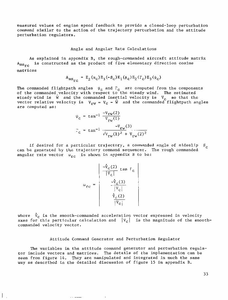
measured values of engine speed feedback to provide a closed-loop perturbation command similar to the action of the trajectory perturbation and the attitude perturbation regulators.
Angle and Angular Rate Calculations
A s explained in appendix B, the rough-commanded aircraft attitude matrix Aasrc matrices
is constructed as the product of five elementary direction cosine
= E2bc)E3(-Bc)E1 (4c)E2(rc)E3($c) 'asr c
The commanded flightpath angles $c and rc of the commanded_velocity with respect to the steady wind. steady wind is W and the commanded ineztial velocity is Vc so that the vector relative velocity is are computed as:
are computed from the components The estimated
vrw = v, - W and the commanded flightpath angles
If desired for a particular trajectory, a commanded angle of sideslip The rough commanded 6, can be generated by the trajectory command sequencer.
angular rate vector wrc is shown in appendix B to be:
where axes for this particular calculation and is the magnitude of the smooth- commanded velocity vector.
9, is the smooth-commanded acceleration vector expressed in velocity
Attitude Command Generator and Perturbation Regulator
The variables in the attitude command generator and perturbation regula- tor include vectors and matrices. The details of the implementation can be seen from figure 14. They are manipulated and integrated in much the same way as described in the detailed discussion of figure 15 in appendix B.
33

Commanded Moment C o e f f i c i e n t s and Moment T r i m Map
The commanded moment v e c t o r i s f i r s t ob ta ined from t h e commanded angu la r a c c e l e r a t i o n 8, by m a t r i x m u l t i p l i c a t i o n by t h e i n e r t i a l m a t r i x J. Then t h e moment c o e f f i c i e n t s are obtained by d i v i d i n g t h e p i t c h i n g to rque component by GSC and t h e r o l l and yaw to rque components by ijsb. The moment trim map invo lves both t a b u l a r i n t e r p o l a t i o n s and a l g e b r a i c equa t ion s o l u t i o n s . For t h e l a te ra l response, t h e r o l l and yaw torque c o n t r i b u t i o n s due t o commanded a n g l e of a t t a c k , r o l l , and yaw rates are c a l c u l a t e d from t a b u l a r d a t a . The remaining p o r t i o n of t h e to rques r equ i r ed t o produce t h e commanded r o l l and yaw acce le ra - t i o n s can b e expressed i n two simultaneous l i n e a r a l g e b r a i c equa t ions i n t h e l a t e ra l c o n t r o l s ; t h e equa t ions are solved f o r t h e r equ i r ed rudder , and l a t e ra l s t i c k d e f l e c t i o n . The a i l e r o n and s p o i l e r are t h e n given as f u n c t i o n s of t h e la teral s t i c k . The p i t c h i n g torque c o n t r i b u t i o n due t o t h e cormanded ang le of a t t a c k , a i l e r o n and s p o i l e r d e f l e c t i o n s , and commanded p i t c h ra te i s then ca l - c u l a t e d using t a b u l a r d a t a . It i s s u b t r a c t e d from t h e t o t a l r equ i r ed p i t c h i n g torque t o f i n d t h e to rque c o n t r i b u t i o n needed from t h e h o r i z o n t a l s t a b i l i z e r . A t a b l e of torque vs commanded a n g l e of a t t a c k f o r v a r i o u s s t a b i l i z e r de f l ec - t i o n s i s then i n t e r p o l a t e d t o f i n d t h e r equ i r ed s t a b i l i z e r d e f l e c t i o n .
This completes t h e d e s c r i p t i o n of t h e c a l c u l a t i o n s c a r r i e d out f o r t h e s imula t ion of TAFCOS. d i g i t a l computer 2 0 t i m e s p e r second. To provide i n s i g h t i n t o t h e system, and f o r convenience and f l e x i b i l i t y i n t h e s i m u l a t i o n , a number of s p e c i a l subrou- t i n e s w e r e employed t o execute v e c t o r and ma t r ix computations and f o r one- and two-dimensional t a b l e i n t e r p o l a t i o n s as w e l l as f o r r eco rd ing computer ou tpu t . However, when t h e TAFCOS concept w a s f l i g h t t e s t e d , t h e a i r b o r n e computer requirements were reduced t o a minimum. Matr ix c a l c u l a t i o n subrou t ines w e r e replaced by e f f i c i e n t i n - l i n e coding, t a b u l a r d a t a w e r e replaced by piecewise l i n e a r a n a l y t i c expres s ions , and slow and f a s t loops w e r e employed.
These c a l c u l a t i o n s must b e c a r r i e d ou t by t h e a i r b o r n e
34

APPENDIX B
E2(ct) =
MATHEMATICAL DETAIL
cos ct 0 - s i n ct
0 1 0
s i n ct 0 cos ct
NOMENCLATURE
a l l a12 a13
a21 a22 a23
a31 a32 a 3 3
d i r e c t i o n cos ine matrix r e p r e s e n t a t i o n of a r o t a - t i o n a l t ransformation
A =
Aasr c
Avs
* dA A = - d t
d i r e c t i o n c o s i n e m a t r i x r ep resen t ing r o t a t i o n from space t o body axes
d i r e c t i o n c o s i n e ma t r ix r ep resen t ing t h e r o t a t i o n from space t o rough commanded a i r c r a f t body axes
d i r e c t i o n c o s i n e ma t r ix r e p r e s e n t i n g t h e r o t a t i o n from space t o veloc- i t y axes
t i m e d e r i v a t i v e of t h e ma t r ix A
A-1 = Aks i n v e r s e and t r anspose of t h e or thogonal ma t r ix as
a l l , a32 Y
etc.
Ex(Y)
ha
hS
Ja
I
c o s i n e of a n g l e between axes of two coord ina te systems as i n d i c a t e d by t h e s u b s c r i p t s
elementary d i r e c t i o n c o s i n e ma t r ix r e p r e s e n t i n g a r o t a t i o n through t h e ang le y about t h e a x i s x. For example:
angular momentum v e c t o r of t h e a i r c r a f t i n space axes
t h e i d e n t i t y ma t r ix 3 x 3
ma t r ix r e p r e s e n t a t i o n of t h e i n e r t i a o p e r a t o r of t h e a i r c r a f t i n body axes 3 x 3
35
I
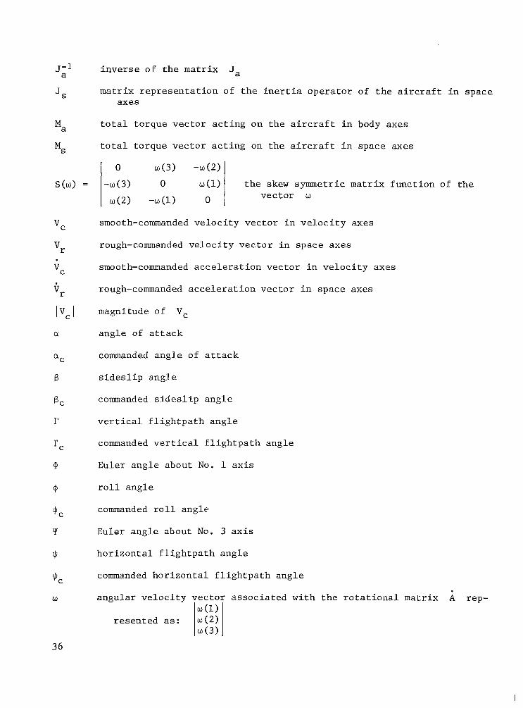
J;l i n v e r s e of t h e ma t r ix Ja
ma t r ix r e p r e s e n t a t i o n of t h e i n e r t i a o p e r a t o r of t h e a i r c r a f t i n space axes
JS
0 w ( 3 ) - w ( 2 )
S(w) = -w(3 ) 0 ~(1) w ( 2 ) - w ( l ) 0
t o t a l t o rque vec to r a c t i n g on t h e a i r c r a f t i n body axes
t o t a l t o rque v e c t o r a c t i n g on t h e a i r c r a f t i n space axes
Ma
MS
t h e skew symmetric matrix f u n c t i o n of t h e vec to r w
smooth-commanded v e l o c i t y vec to r i n v e l o c i t y axes
rough-commanded v e l o c i t y v e c t o r i n space axes
VC
'r
'r
Ivc I a
6
9
+ C
Y
J,
smooth-commanded a c c e l e r a t i o n v e c t o r i n v e l o c i t y axes
rough-commanded a c c e l e r a t i o n v e c t o r i n space axes
magnitude of Vc
ang le of a t t a c k
commanded a n g l e o f a t t a c k
s i d e s l i p a n g l e
commanded s i d e s l i p a n g l e
v e r t i c a l f l i g h t p a t h a n g l e
commanded v e r t i c a l f l i g h t p a t h ang le
Euler ang le about No. 1 axis
r o l l ang le
commanded r o l l ang le
Euler ang le about No. 3 a x i s
h o r i z o n t a l f l i g h t p a t h a n g l e
commanded h o r i z o n t a l f l i g h t p a t h ang le
w angu la r v e l o c i t y v e c t o r a s s o c i a t e d w i t h t h e r o t a t i o n a l ma t r ix A rep- w ( l )
w ( 3 ) r e sen ted as: l w ( 2 ) I
36

0 Euler a n g l e about t h e N o . 2 axis
W a angu la r v e l o c i t y v e c t o r of a i r c r a f t axis system (a s soc ia t ed w i t h i a s ) expressed i n a i r c r a f t body axis system
wC smooth-commanded angu la r v e l o c i t y v e c t o r ( a s soc ia t ed w i t h ) i n body axes
rough-commanded angular v e l o c i t y vec to r ( a s soc ia t ed w i t h A,,s) i n Wrc v e l o c i t y axes
Subsc r ip t s
a a i r c r a f t body axis system
C commanded
r rough
S space axis system
V v e l o c i t y a x i s system
Other Nota t ions
t i m e d e r i v a t i v e
-1 i n v e r s e of a ma t r ix
COORDINATE SYSTEMS
TAFCOS r e q u i r e s t h e d e f i n i t i o n of several coord ina te systems. All are right-handed, t h ree -ax i s or thogonal systems. Vectors are expressed by t h e i r t h r e e components i n t h e a p p r o p r i a t e system. Sketch (d) i l l u s t r a t e s t h e cha in of coord ina te systems t h a t t ransforms q u a n t i t i e s from i n e r t i a l space coordi- n a t e s t o a i r c r a f t body axes. The i n e r t i a l space axis system i s cen te red a t t h e
INERTIAL VELOCITY STAB1 L I T Y SPACE
AXIS HEADING WIND TUNNEL AIRCRAFT BODY
Sketch (d)
37
I . -
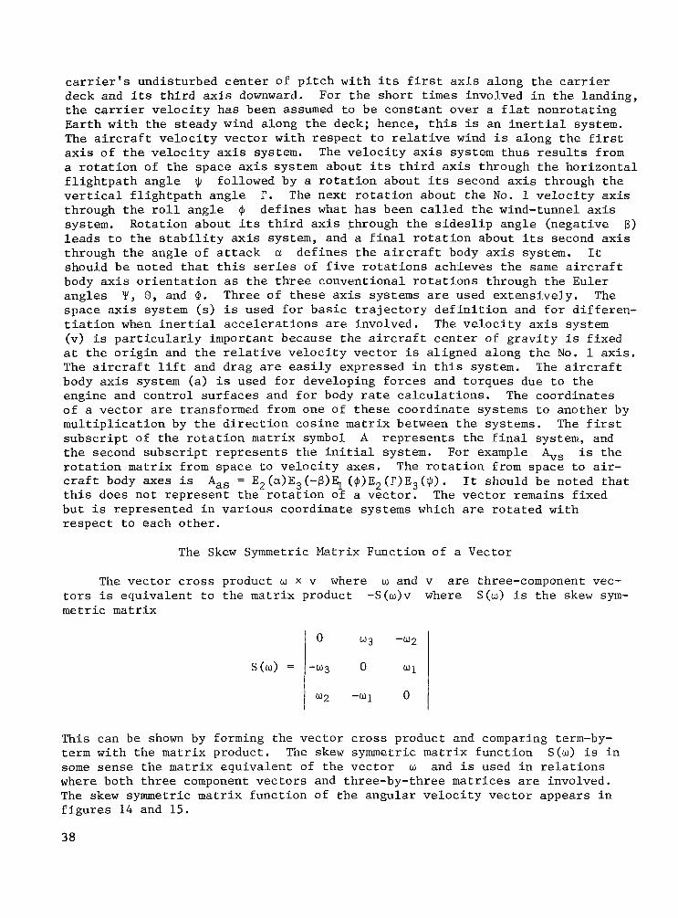
c a r r i e r ' s undis turbed c e n t e r of p i t c h w i t h i t s f i r s t a x i s a long t h e c a r r i e r deck and i t s t h i r d a x i s downward. For t h e s h o r t t i m e s involved i n t h e landing, t h e carrier v e l o c i t y has been assumed t o b e cons t an t over a f l a t nonro ta t ing Ea r th w i t h t h e s t eady wind along t h e deck; hence, t h i s is an i n e r t i a l system. The a i r c r a f t v e l o c i t y v e c t o r w i t h r e s p e c t t o r e l a t i v e wind i s along t h e f i r s t axis of t h e v e l o c i t y axis system. The v e l o c i t y a x i s system t h u s r e s u l t s from a r o t a t i o n of t h e space axis system about i t s t h i r d a x i s through t h e h o r i z o n t a l f l i g h t p a t h a n g l e $ followed by a r o t a t i o n about i t s second a x i s through t h e v e r t i c a l f l i g h t p a t h a n g l e r. The nex t r o t a t i o n about t h e No. 1 v e l o c i t y a x i s through t h e r o l l a n g l e 9 system. Rotat ion about i t s t h i r d axis through t h e s i d e s l i p ang le (nega t ive 6) l e a d s t o t h e s t a b i l i t y axis system, and a f i n a l r o t a t i o n about i t s second a x i s through t h e ang le of a t t a c k c1 d e f i n e s t h e a i r c r a f t body a x i s system. It should b e noted t h a t t h i s series of f i v e r o t a t i o n s ach ieves t h e s a m e a i r c r a f t body a x i s o r i e n t a t i o n as t h e t h r e e convent ional r o t a t i o n s through t h e Euler ang le s Y , 0 , and @. Three of t h e s e a x i s systems are used ex tens ive ly . The space a x i s system (s) i s used f o r b a s i c t r a j e c t o r y d e f i n i t i o n and f o r d i f f e r e n - t i a t i o n when i n e r t i a l a c c e l e r a t i o n s are involved. The v e l o c i t y a x i s system (v) i s p a r t i c u l a r l y important because t h e a i r c r a f t c e n t e r of g r a v i t y i s f i x e d a t t h e o r i g i n and t h e r e l a t i v e v e l o c i t y v e c t o r is a l igned along t h e No. 1 a x i s . The a i r c r a f t l i f t and d rag are e a s i l y expressed i n t h i s system. The a i r c r a f t body a x i s system (a) i s used f o r developing f o r c e s and to rques due t o t h e engine and c o n t r o l s u r f a c e s and f o r body rate c a l c u l a t i o n s . of a vec to r are transformed from one of t h e s e coord ina te systems t o another by m u l t i p l i c a t i o n by t h e d i r e c t i o n cos ine ma t r ix between t h e systems. The f i r s t s u b s c r i p t of t h e r o t a t i o n ma t r ix symbol A r e p r e s e n t s t h e f i n a l system, and t h e second s u b s c r i p t r e p r e s e n t s t h e i n i t i a l system. For example bS is t h e r o t a t i o n matrix from space t o v e l o c i t y axes . The r o t a t i o n from space t o a i r - c r a f t body axes is t h i s does n o t r e p r e s e n t t h e r o t a t i o n of a v e c t o r . The v e c t o r remains f i x e d b u t i s r ep resen ted i n v a r i o u s coord ina te systems which are r o t a t e d wi th r e s p e c t t o each o t h e r .
d e f i n e s what h a s been c a l l e d t h e wind-tunnel a x i s
The coord ina te s
A,, = E2(a)E3(-B)E1 (+)E2(r)E3($) . It should be noted t h a t
The Skew Symmetric Matrix Function of a Vector
The v e c t o r c r o s s product w x v where w and v are three-component vec- t o r s is equ iva len t t o t h e ma t r ix product -S(w)v where S(w) i s t h e skew sym- m e t r i c ma t r ix
l o w 3
This can be shown by forming the v e c t o r c r o s s product and comparing term-by- t e r m w i th t h e ma t r ix product. The skew symmetric ma t r ix f u n c t i o n S(w) i s i n some sense t h e ma t r ix equ iva len t of t h e v e c t o r w and i s used i n r e l a t i o n s where both t h r e e component v e c t o r s and three-by-three matrices are involved. The skew symmetric ma t r ix func t ion of t h e angular v e l o c i t y v e c t o r appears i n f i g u r e s 14 and 15.
38

The Vector Function of a Matrix
S(w) =
L e t t h e r o t a t i o n matrix A b e
0 w ( 3 ) -w (2 )
- w ( 3 ) 0 w ( 1 )
w ( 2 ) - w ( l ) 0
a31 a32 a 3 3
A = a 2 1 a22
w =
Then t h e v e c t o r f u n c t i o n of A is def ined as
w ( 1 )
w ( 2 )
w ( 3 )
In some sense Q(A) i s t h e v e c t o r equ iva len t of t h e ma t r ix A as can be seen by no t ing t h a t under a p p r o p r i a t e cond i t ions t h e Q and S func t ions can- c e l . I n gene ra l Q ( S ( w ) ) = w and f o r a skew symmetric ma t r ix A , S ( Q ( A ) ) = A. The v e c t o r f u n c t i o n of a r o t a t i o n a l m a t r i x Q(A) appears i n f i g u r e 14 where i t i s used t o convert a ma t r ix r e p r e s e n t i n g an angular e r r o r i n t o a v e c t o r t h a t can b e added t o ano the r v e c t o r r e p r e s e n t i n g an angu la r v e l o c i t y e r r o r t o form a t o t a l e r r o r v e c t o r .
This would s t r i c t l y be t h e angu la r v e l o c i t y v e c t o r a s s o c i a t e d wi th This i n t u r n depends on t h e t i m e d e r i v a t i v e s of a l l f i v e ang le s involved i n
hiasrc.
39

t h e t ransformation. However, only t h e major components w e r e implemented f o r t h i s a p p l i c a t i o n . Hence, only t h e t i m e d e r i v a t i v e s of qC and rc w e r e used t o command open-loop a t t i t u d e rate. q C and rc , which d e f i n e t h e o r i e n t a t i o n of t h e re la t ive v e l o c i t y axis system, may change over a wide range du r ing an extended pe r iod of t$me as t h e f l i g h t p a t h i s descr ibed. Thus, t h e i r t i m e d e r i v a t i v e s can ma in ta in s u b s t a n t i a l , slowly changing values . Furthermore, t h e s e commanded ang le s are computed from t h e components of t h e commanded a i r c r a f t v e l o c i t y w i t h r e s p e c t t o s t eady wind and hence are n o i s e f r e e . aC changes r a p i d l y t o i n i t i a t e maneuvers, c o n t a i n s a n o i s e component due t o feed- back from t h e t r a j e c t o r y r e g u l a t o r , and has ze ro average rate of change over r e l a t i v e l y s h o r t pe r iods . B, , which would be needed f o r crabbing and decrabbing, w a s n o t used i n t h e s e s lmula t ions and i n any event would have only s h o r t d u r a t i o n , nonzero v a l u e s of t i m e d e r i v a t i v e . Commanded r o l l ang le 9, changes of s h o r t d u r a t i o n . The angu la r v e l o c j t y v e c t o r of t h e v e l o c i t y a x i s system i s given i n t e r m s of t h e a n g l e rates
The commanded f l i g h t p a t h a n g l e s
On t h e o t h e r hand, commanded a n g l e of a t t a c k
Commanded s i d e s l i p
about t h e v e l o c i t y axis l i k e w i s e is c h a r a c t e r i z e d by r ap id
J1, and f C as:
Now q C and Tc are t h e f l i g h t p a t h ang le s generated t o command t h e air- c r a f t c e n t e r of g r a v i t y t o fol low t h e t r a j e c t o r y . The t r a j e c t o r y has been def ined i n ter?s of t h e corresponding a c c e l e r a t i o n s . a c c e l e r a t i o n Vr ( f i g . 10) is expressed i n space axes a t t h e inpu t t o t h e tra- j e c t o r y command gene ra to r and produces t h e smooch comm?nded a c c e l e r a t i o n i n v e l o c i t y axes. The f l i g h t p a t h ang le rates Tc and J1c depend on components of t h i s a c c e l e r a t i o n t h a t are perpendicular t o t h e v e l o c i t y v e c t o r and on t h e magnitude of t h e v e l o c i t y
The rough commanded
9,
l V c ] :
S u b s t i t u t i n g t h e s e v a l u e s i n t o t h e expres s ion f o r wrc g ives t h e rough commanded open-loop angu la r v e l o c i t y , which i s used as an inpu t t o t h e a t t i t u d e command generator i n f i g u r e 10.
The Matrix Form of t h e Ro ta t iona l Dynamic Equation
The r o t a t i o n a l dynamic p o r t i o n of t h e a i r c r a f t s imu la t ion r ep resen ted i n t h e a i r c r a f t block a t t h e extreme r i g h t end of f i g u r e 3 uses a matrix formula- t i o n of t h e dynamic equat ion der ived below. L e t Ms and Ma be t h e t o t a l t o rque - aerodynamic and p ropu l s ive - expressed i n t h e i n e r t i a l frame and t h e body frame r e s p e c t i v e l y . L e t hs and ha be t h e angu la r momentum v e c t o r i n space and body coord ina te s . L e t J, and J, be t h e i n e r t i a ma t r ix i n space and body axes. L e t wa be t h e angu la r v e l o c i t y vec'ior of t h e body axes wi th r e s p e c t t o t h e space axes expressed i n body axes coord ina te s and l e t A,,
40

b e t h e r o t a t i o n ma t r ix from t h e space axes t o t h e body axes. Note t h a t t h e vec to r q u a n t i t i e s are a l l three-element column v e c t o r s ; t h a t is ,
and t h e matrices are three-by-three a r r a y s . Now
M a = 'as's
.ha =
A,, = S(wa)Aas
from a preceding s e c t i o n of t h i s appendix. Also by n e g l e c t i n g spinning r o t o r s w e have
ha = J a w a
and because Ja i s cons t an t i n t h e body frame
ha = Jaha
Furthermore, t h e b a s i c dynamic r e l a t i o n i n i n e r t i a l axes i s
ks = Ms
The r e l a t i o n us ing t h e e a s i l y a v a i l a b l e q u a n t i t i e s by t h e fol lowing manipulations:
Ma and ha may now be found
ha = Aashs
La = h, h + AasGs = J a A a as s
then
A block diagram of t h i s expres s ion i s included i n t h e f i r s t s e c t i o n of f i g u r e 15.
The f i n a l p o r t i o n of f i g u r e 15 i l l u s t r a t e s how t h e angular v e l o c i t y vec- t o r wa t i o n cosine m a t r i x Aas. The v e c t o r wa is f i r s t used t o c o n s t r u c t t h e skew symmetric m a t r i x func t ion S(wa). d i r e c t i o n cos ine m a t r i x
is i n t e g r a t e d t o o b t a i n t h e a i r c r a f t a t t i t u d e expressed as t h e d i r e c -
Then t h e r e l a t i o n f o r t h e d e r i v a t i v e of a is implemented by t h e m a t r i x Kas = S(w,)A,,
4 1

multiplication indicated. to give Aas. The Gram-Schmidt orthogonalization is then required, otherwise cumulative computer round-off error would soon lead to a nonorthogonal matrix in which individual elements exceed unity. Angles are treated throughout the system by manipulation of their direction cosine matrices. This completes the aircraft rotational dynamics. However, for purposes of angular readout during the simulation, a computer routine has been developed (ref.8) that further dis- plays the Euler angles corresponding to the direction cosine matrix
This is followed by a straightforward integration
Aas:
42

REFERENCES
1. Meyer, G.; and Cicolani, L. S.: A Formal Structure for Advanced Automatic Flight-Control Systems. NASA TN D-7940, 1975.
2. Wehrend, W.; and Meyer, G.: DHC-6 Flight Tests of the Total Automatic Flight Control System (TAFCOS) Concept. NASA TP-1513. (In preparation)
3. Smith, G. Allan; McNeill, Walter E.; and Huff, Richard B.: A Comparison of Restructured Designs for the Automatic Carrier Landing System. Pro- ceedings of Flight Control Systems Criteria Symposium, U.S. Naval Post Graduate School, July 1978.
4 . Smith, G. Allan; and Meyer, George: Total Aircraft Flight-Control System - Balanced Open- and Closed-Loop Control With Dynamic Trim Maps. Proceedings of the Third Digital Avionics Systems Conference, Ft. Worth, Texas, Nov. 1979, IEEE Catalog No. 79CH1518-0.
5. Cicolani, L. S.; Sridhar, B.; and Meyer, George: Configuration Manage- ment and'Automatic Control of an Augmentor Wing Aircraft with Vectored Thrust. NASA TP-1222, 1979.
6 . Meyer, G.: On the Use of Euler's Theorem on Rotations for the Synthesis of Attitude Control Systems. NASA TN D-3643, 1966.
7. Sidar, M.; and Doolin, B. F.: On 'the Feasibility of Real-Time Predictions of Aircraft Carrier Motion at Sea. NASA TM X-62454, 1975.
8. Meyer, G.; Lee, H. Q.; and Wehrend, W. R., Jr.: A Method for Expanding a Direction Cosine Matrix into an Euler Sequence of Rotations. NASA TM X-1384, 1967.
43

Condit ion
Maximum deck displacement due t o p i t c h and heave Mean touchdown e r r o r ( long) Standard d e v i a t i o n of touchdown e r r o r Mean ramp c l e a r a n c e Standard d e v i a t i o n o f ramp c l ea rance Touchdowns beyond a l lowable area Touchdowns s h o r t of a l lowable area
TABLE 2.- CLOSED TRAJECTORY PARAMETERS.
Dispers ion
2.4 m (8 f t ) 3 . 9 m (13 f t ) 6.7 m (22 f t ) 4.9 m (16 f t ) 0.9 m (3 f t ) 6 0
Segment number
1 2 3 4 5 6 7 8 9
10 11 12 13 1 4
T r a j e c t o r y type
S t r a i g h t S t r a i g h t Helical S t r a i g h t Helical C i r c u l a r l eve l S t r a i g h t C i r c u l a r S t r a i g h t C i r c u l a r S t r a i g h t
1 e.vel c 1 imb
1 1
descend descend level
-
Climb angle ,
deg
--- 3 3 3 3
---
-6 I -0.9 ---
Pa th l e n g t h
m
512 349
9 14 --- ---
1755
3947
628 2509 1161
610
---
---
f t
1680 1146
3000 --- ---
5760
12950
2060 82 30 3810 2000
---
Radius
44

MARSHAL POINT
DESCENT
APPROACH COURSE
/ -- - - - -- --- ---.- - ---r\= -- --
LOCKON
TIPOVER
-- - - - FOLLOW1 NG -
Figure 1.- A i r c r a f t carrier landing s i t u a t i o n .

COMMANDED
ROUGH- SMOOTH- COMMANDED COMMANDED COMMANDED COMMANDED COMMANDED LIFT AN0 DRAG 'MMANDEo ANGULAR MOMENT TRAJECTORY ACCELERATION COEFFICIENTS ALPHA ACCELERATION COEFFICIENTS
MAP (INVERT MOMENT
TABLES)
TRAJECTORY TRAJECTORY FORCE TRIM MAP uc COMMAND
SEQUENCER
COMMANDED ROLL ANGLE
I COMMANDED SPOILERS
ICOMMANDEO 1 RUDDER .
AIRCRAFT
COMMANDED STABILIZE\
I rc $0 COMMANDED FLIGHTPATH
ANGLES
COMMANDED THROTTLE
'TC ENGINE THRUST ANGLE COMMANDED THRUST
COEFFICIENT
Figure 2.- Basic open-loop feed-forward c o n t r o l concept.
*
FEEDBACK LOOPS a 0
I 4 s
TABLE IINVERTEOI
I
COMMANDED COMMANDED
w
AILERON TRAJECTORY COMMANDED ROLL ANGLE Oc f, REGULATOR ATTITUDE &
REGULATOR COMMANDED COMMANDED COMMANDED
ANGULAR MOMENT SPOILERS ROUGH- COMMANDED COMMANDED
COMMANDED
ACCELERATION COEFFICIENTS
DESIRED TRAJECTORY TRAJECTORY
SEGMENTS
rc $c
COMMANDED COMMANDED FLIGHTPATH
ANGLES COEFFICIENT cTc . ENGINE THRUST THROTTLE ANGLE COMMANDED THRUST
TABLE (INVERTED]
AIRCRAFT
Figure 3 . - T o t a l a i r c r a f t f l i g h t - c o n t r o l system (TAFCOS).

1.8
1.6
1.4
0 J 0 1.2 c’
0 5 -
8 t 2 n a I -6
1.0 W
- J .8
z I
8
.4
.2
0
COMMANDED THRUST COEFFICIENT, CT,
-.6 -.4 -.2 0 .2 .4 COMMANDED DRAG COEFFICIENT CD,
Figure 4 . - Force t r i m map.
47

ROUGH-COMMANDED VERTICAL POSITION, ft
SMOOTH-COMMANDED VERTICAL POSITION, ft
ACTUAL VERTICAL POSITION, ft
ROUGH-COMMANDED VERTICAL POSITION, f t
SMOOTHCOMMANDED VERTICAL POSITION, ft
ACTUAL VERTICAL POSITION, ft
0 L \ i m
-500 r r j -150m
0 0
0 10 20 30 40 50 60- TIME, sec
-500 r
7 9 11 13 15 17 19 TIME, sec EXPANDED SCALE
(a) T ra j ec to ry v a r i a b l e s .
F igure 5.- Tip-over run without tu rbulence .
48

START DECK MOTION TRACKING
TOUCH DOWN
1 i TIP OVER
RO UG H-COM MAN D ED VERTICAL VELOCITY, Wsec
ROUGHCOMMANDED VERTICAL ACCELERATION, 9
-.I
mlsec SMOOTH-COMMAN DE D VERTICAL VELOCITY, Wsec
c
I I I I
I I I I I
ACTUAL mlsec VERTICAL VELOCITY, Wsec
. ~~~ .- ~
SMOOTH-COMMAN DED VERTICAL ACCELERATION, g
-. 1 I I I I I
ACTUAL VERTICAL ACCELERATION, 9
- 1 .. 0 10 20 30 40 50 60
TIME, sec
( a ) T r a j e c t o r y v a r i a b l e s - Concluded.
F igure 5.- Tip-over run wi thout tu rbulence - Continued.

10 r DECK VERTICAL BISPLACEM ENT FROM REFERENCE POSITION, f?
-10 I I I I I
DECK POSITION FOLLOWING COMMAND, f t
-10
DECK VELOCITY FOLLOWING COMMAND, Wsec
-5
1 DECK ACCELERATION FOLLOWING COMMAND, g
-. 1 0 10 20 30 40 50 60
TIME, sec
(b) V e r t i c a l deck motion v a r i a b l e s .
F igu re 5.- Tip-over run without t u rbu lence - Continued.
50
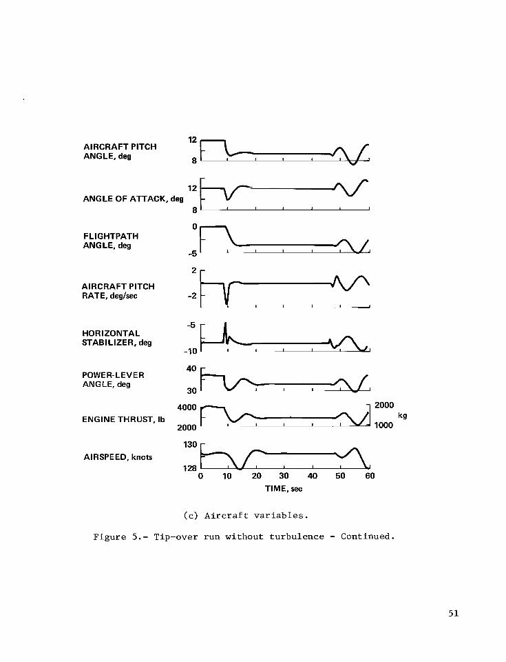
8
AIRCRAFT PITCH ANGLE, deg
- -~ 12
8
0
ANGLE OF ATTACK, deg I I I 1 1 1
FLIGHTPATH - ANGLE, deg
-5 I I 1 I
-2 AIRCRAFT PITCH RATE, deglsec
HORIZONTAL STABILIZER, deg
-10 I 1 I I I
30
4000
2000
130
2000
I I 1000
40 ! POWER- LEVER ANGLE, deg
kg ENGINE THRUST, Ib
- AIRSPEED, knots
I 1 128 0 10 20 30 40 50 60
TIME, sec
(c ) A i r c r a f t v a r i a b l e s .
F igu re 5.- Tip-over run without t u rbu lence - Continued.
5 1
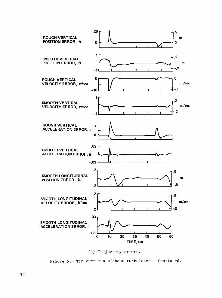
0 ROUGH VERTICAL POSITION ERROR, f t
SMOOTH VERTICAL VELOCITY ERROR, Wsec
-
SMOOTH VERTICAL POSITION ERROR, ft
-1
-.2
0
ROUGH VERTICAL ACCELERATION ERROR, g
.03 - SMOOTH VERTICAL ACCELERATION ERROR, g
-.03 I I I I I
SMOOTH LONG ITUDl N AL POSITION ERROR, ft
-2
m/sec
m/sec
m
mlsec 2+-4:: . 0 3 a
SMOOTH LONG ITUDI NAL VELOCITY ERROR, ft/sec
-2
SMOOTH LONGITUDINAL ACCELERATION ERROR, g
-.03 0 30 20 30 40 50 60
TIME, sec
(d) T r a j e c t o r y e r r o r s .
F igure 5.- Tip-over run wi thout tu rbulence - Continued.
52

VERTICAL FEED FORWARD SPECIFIC FORCE SIGNAL f,,, g -” E-6,
-1.1
VE RTlCAL FEEDBACK SPECIFIC FORCE SIGNAL f,, , 9
-.01
VERTICAL TOTAL SPECIFIC FORCE SIGNAL ftc, 9
-1 .I
0 LONGITUDINAL FEED FORWARD SPECIFIC FORCE SIGNAL f,,, g __
-.I - I I I I I
LONG ITUD I N AL FEEDBACK SPECIFIC FORCE SIGNAL f,, , 9
.02
-.02 I I I I
O:
LONG I TU D1 N AL TOTAL SPECIFIC FORCE SIGNAL ftc, g
-.I 0 10 20 30 40 50 60
TIME, sec
(e) Internal feed-forward and feedback signals.
Figure 5.- Tip-over run without turbulence - Continued.
5 3

POWER-LEVER ANGLE, deg 40 c I I 1 I 1 20 1 I
2000 ENGINE THRUST, Ib
FORWARD VELOCITY WITH RESPECT TO DECK, knots
.05 - FOR WARD ACCE L E RAT1 ON WITH RESPECT TO DECK, g
I I
AIRSPEED, knots I3O 1
I I I I 1 J 125 ' 0 10 20 30 40 50 60
TIME, sec
( f ) Radar s i g n a l l o s t a t 150 m ( 4 9 3 f t ) be fo re touchdown, t h r o t t l e h y s t e r e s i s included. P l o t s of major v a r i a b l e s t h a t w e r e no t i ceab ly a f f e c t e d .
F igure 5.- Tip-over run without tu rbulence - Continued.
54
I

m
COMMANDED LIFT 1.2 COE F Fl Cl ENT
I L
10 2ol -
I I I
0
-1 0 O I 0
0 0 0 . 0
0
0 0
0
0
0
0 0
-20 I I I I I 0 90 180 270 360
DECK-MOTION PHASE AT TOUCHDOWN, deg
(g) Touchdobm e r r o r as a func t ion of deck-motion phase.
ACTUAL LIFT - COEFFICIENT I
COMMANDED DRAG CO E F F I CI ENT
0-
0 10 20 30 40 50 60 TIME, sec
ACTUAL DRAG COE FFlCl ENT
(h) Commanded and a c t u a l l i f t and drag c o e f f i c i e n t s .
F igure 5.- Tip-over run wi thout tu rbulence - Concluded.
55

0
ROUGH-COMMANDED VERTICAL POSITION, f t
0
SMOOTHCOMMANDED VERTICAL POSITION, ft
ACTUAL VERTICAL POSITION,
ROUGHCOMMANDED VERTICAL VELOCITY,
ft -500 0 : olsom mlsec ftlsec
SMOOTHCOMMANDED mlsec VERTICAL VELOCITY, ftlsec
ACTUAL VERTICAL VELOCITY, ftlsec
- 0 I I I I I
0 10 20 30 40 50 60 TIME, sec
(a) Tra j ec to ry v a r i a b l e s .
Figure 6.- Tip-over run wi th turbulence .
56
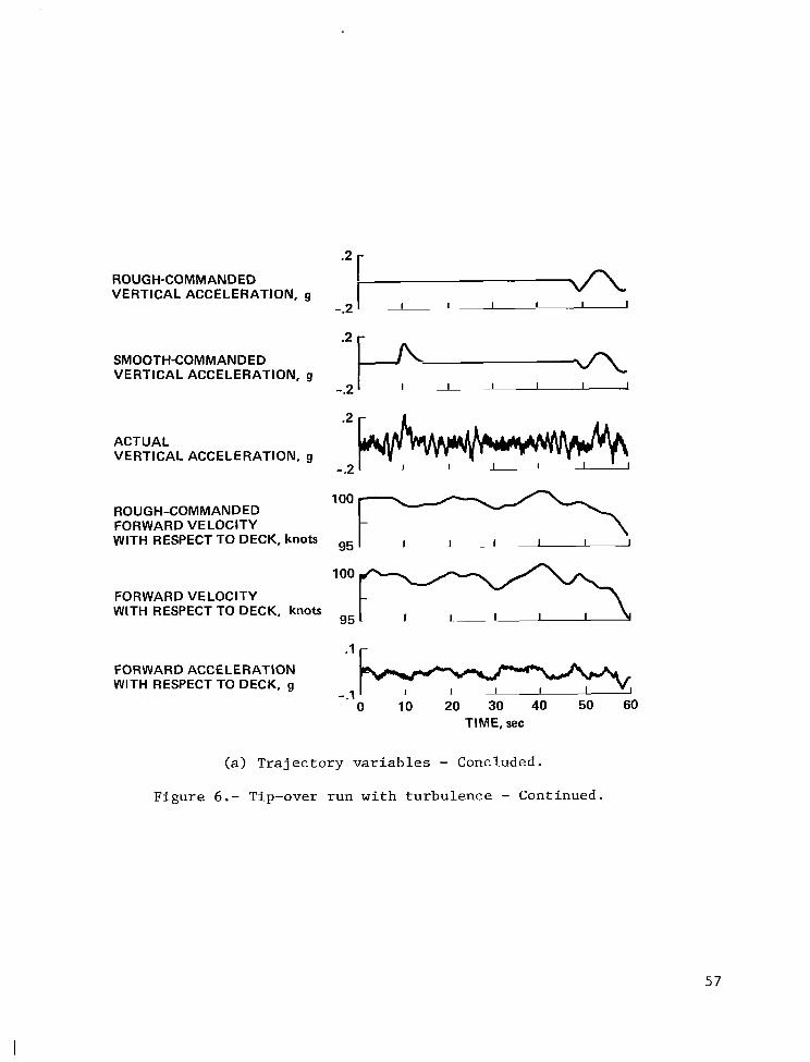
I I I I I I
ROUGH-COMMANDED VERTICAL ACCELERATION, g
-.2
FOR WARD ACCELERATION WITH RESPECT TO DECK, g
- I
SMOOTH-COMMANDED VERTICAL ACCELERATION, g
-.2 I I I
.2
ACTUAL VERTICAL ACCELERATION, g
-.2
loo ll loo s
ROUGH-COMMANDED FORWARD VELOCITY WITH RESPECT TO DECK, knots 95
FORWARD VELOCITY WITH RESPECT TO DECK, knots
95
( a ) T r a j e c t o r y v a r i a b l e s - Concluded.
F igure 6 . - Tip-over run w i t h tu rbu lence - Continued.
57

AIRCRAFT PITCH ANGLE, deg
ANGLE OF ATTACK, deg
FLIGHT PATH ANGLE, deg
AIRCRAFT PITCH RATE, deg/sec
HORIZONTAL STABILIZER, deg
COMMANDED THRUST COE F FlCl ENT
POWER-LEVER ANGLE, deg
ENGINE THRUST, Ib
A I RSPE ED, knots
f
I I I ! I
I 1 1 I I
- 0
-5 I
I
I
30
kg
40 Jl 4000 i j 2ooo
2000 1000
0 10 20 30 40 50 60 TIME, sec
(b) A i r c r a f t v a r i a b l e s .
F igu re 6.- Tip-over run wi th tu rbu lence - Continued.
58

ROUGH VERTICAL POSITION ERROR, ft
SMOOTH VERTICAL
2 - .5 SMOOTH VERTICAL m POSITION ERROR, ft -2 . -.5
ROUGH VERTICAL VELOCITY ERR 0 R, ftlsec
-10
2- SMOOTH VERTICAL VELOCITY ERROR, ft/sec
-2
ROUGH VERTICAL ACCELERATION ERROR, g -.2 I
.2 r
2- SMOOTH LONGITUDINAL POSITION ERROR, I3
1 -
SMOOTH LONGITUDINAL VELOCITY ERROR, ftlsec
-1
.02 SMOOTH LONGITUDINAL ACCELERATION ERROR, g -.02
0 10 20 30 40 50 60 TIME, sec
( c ) T ra j ec to ry e r r o r s .
m
mlsec
Figure 6 . - Tip-over run wi th turbulence - Continued.
59

1 -
m LATERAL POSITION ft
-1
- .2
-.2
1-
LATERAL VELOCITY ft/t/sec mlsec
1 I u -1 ~ -1
2 r
ROLL ANGLE, deg
YAW ANGLE, deg
SIDESLIP ANGLE, deg
ROLL RATE, deglsec
YAW RATE, deglsec
AILERON, deg
I 1 1 I
I I I I I 1
-1 - i ~I I I J
It-
5 r
RUDDER, deg
-2 ' I
0 10 20 30 40 50 60 TIME, sec
(d ) Lateral v a r i a b l e s .
F igu re 6.- Tip-over run wi th tu rbu lence - Continued.
60

LONGlTUDl NAL TURBULENCE,ft/sec -10 -
LATE R AL TU R BU L ENC E, ft/sec
VERTICAL TURBULENCE, ft/sec
VERTICAL RADAR ERROR, ft
HORIZONTAL RADAR ERROR, ft
10 - -3
m/sec
1 1 1 I I -3 -10
m/sec
-10' I I I I I
5 r - 1
m
-5' 1 I I I I
m
0 10 20 30 40 50 60 TIME, sec
(e) Turbulence and radar noise inputs.
. I
0
COMMANDED DRAG COE FFlCl ENT I
.1
0
- ACTUAL DRAG COEFFICIENT
I 1 I I I I
1.2 COMMANDED LIFT COE F FI CI ENT
.8 I I 1 I I I
1.2 ACTUAL LIFT COEFFICIENT
.8 I i I I I I I 0 10 20 30 40 50 60
TIME, sec
(f) Commanded and actual lift and drag coefficients.
Figure 6.- Tip-over run with turbulence - Concluded.
61

ft
m 75r * . . .
. *
! : I ! e .
0 .
. . I
. . . . .
. . : ' r - ! . I .
. * a
. . 0 . .
. 1 .
. . . ! . I
-50 I I I I 1 I
I:! -10
. e . . 0 . . . . . . 1 I I I I
. . *
0 90 180 270 360 DECK PHASE AT TOUCHDOWN, deg
Figure 7.- Landing p o s i t i o n e r r o r s f o r 160 runs wi th turbulence.
6 2

STEP GUST, knots
GROUND SPEED, knots
AIRSPEED, knots
( a ) T r a j e c t o r y v a r i a b l e s .
F igure 8.- Level r u n wi th s t e p gus t d i s tu rbances .
6 3

ALTITUDE, ft
450
LATERAL ACCELERATION, g
20tT---5 LATERAL POSITION, ft
-20 . - -5
I I
FORWARD ACCELERATION, g
1 .. I
VERTICAL ACCELERATION, g
-.5 *5*J 0 25 50 75 100 125 150
TIME, sec
(a) Trajectory variables - Concluded.
Figure 8.- Level run with step gust disturbances - Continued.
64

Oh-
HO R I ZONTAL STABILIZER, deg
POWER-LEVER ANGLE, deg
THRUST, Ib
PITCH ANGLE, deg
I I I I I . A ~- I -20 I I
I
' 7 ~ ] :'M kg
I I
ANGLE OF ATTACK, deg I
5 -
FLIGHTPATH ANGLE, deg
0 25 50 75 100 125 150 TIME, sec
(b) Aircraft variables.
Figure 8.- Level run with step gust disturbances - Continued.
65

PITCH RATE, deg/sec I I I I I
BANK ANGLE, deg -10
I I
-
HEADING ANGLE, deg lo 1-1 /J- I I I 1 I I -10 ' v
AILERON ANGLE, deg
-1 0
0 25 50 75 100 125 150 TIM E, sec
(b) A i r c r a f t v a r i a b l e s - Concluded.
,
Figure 8.- Level run wi th s t e p g u s t d i s t u r b a n c e s - Continued.
66

DYNAMIC PRESSURE, lb/$
40
- COMMANDED LIFT COEFFICIENT NOT LIMITED .5 I
COMMANDED LIFT COE F F IC1 ENT L I M ITED
I
ACTUAL LIFT COEFFICIENT
.5 COMMANDED DRAG COEFFICIENT NOT LIMITED
-.5
.5 r
I I
COMMANDED DRAG CO E F F IC I ENT LIMITED
.5 - ACTUAL DRAG COEFFICIENT
0 25 50 75 100 125 150 TIME, sec
(c) Lift and drag coefficients.
Figure 8.- Level run w i t h step gust disturbances - Continued.
67

1.8
1 .E
0 1.4
1.2
1 .o
.8
.6
.4
.2
0
1 TRIMMAP PER1 METER
I I I I I
-.4 -.2 0 .2 .4 COMMANDED DRAG COEFFICIENT BEFORE LIMITING,ED
C
Commanded lift vs drag coefficients, not limited.
Figure 8.- Level run with step gust disturbances - Continued.
68

1.8
1.6
1.4
u -I 0 1.2 +- 0 u 1.0
E -
8 t n - 8 -
LL
W
- -I
Lu
I I ~~ I I I -.4 -.2 0 .2 .4
0 - I -.6
L C COMMANDED LIFT COEFFICIENT, C
BOUNDARY FOR -
-
-
-
-
(e) Commanded lift vs drag coefficients.
Figure 8.- Level run with step gust disturbances - Continued.
69

1 .E
1 .f
1.4
J 1.2
I-’
E ii 1.0
0
- 0
LL W 0 0 I- LL -I -8
2 3 I-
3 .6
.4
.2
0
TRIM MAP PERIMETER
I I I 1 I
-.6 -.4 -.2 0 .2 .4 ACTUAL DRAG COEFFICIENT, CD
( f ) Actua l l i f t vs drag c o e f f i c i e n t s .
F igure 8.- Level run wi th s t e p gus t d i s t u r b a n c e s - Concluded.
70
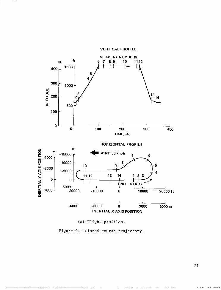
VERTICAL PROFILE
m
300 400[
SEGMENT NUMBERS ft 6 7 8 9 10 1112
I I I I I 1500 - I t - I
I
0 loo[ 0 100 200 300 400
TIME, sec
HORIZONTAL PROFILE
z f t 0 m -1 5000 (I WIND 30 knots
4 X a
I- 5000 1 I
I
- END START I -~~ 1-
-20000 -1 0000 0 10000 20000 f t 2000
I J I ~ 1- I
-6000 -3000 0 3000 6000 m INERTIAL X AXIS POSITION
(a) F l i g h t p r o f i l e s .
F igu re 9.- Closed-course t r a j e c t o r y .
._..._. . . . . . . . . . . .... . ...
7 1

ALTITUDE, ft
INERTIAL X AXIS POSITION, f t
INERTIAL Y AXIS POSITION, ft
VERTICAL VELOCITY, ftlsec
INERTIAL X AXIS VELOCITY, knots
INERTIAL Y AXIS VELOCITY, knots
AIRSPEED, knots
m I I 1 1
1 5000 -
-20000 1 I I
m 4 -5000
-20000 oP-’-lo -5000
mlsec
-30
1 I I
140
120 I I
-
I 1 I 1 -1
0 50 100 150 200 250 300 350 TIME, sec
(b) T r a j e c t o r y v a r i a b l e s .
F igure 9.- Closed-course t r a j e c t o r y - Continued.
72

FLIGHTPATH ANGLE, deg
ANGLE OF ATTACK, deg
PITCH ANGLE, deg
SIDESLIP ANGLE, deg
BANK ANGLE, deg
HEADING ANGLE, deg
I I I I I I I
-5 5c 10 -
20 r
-1 180 80 1 0 50 100 150 200 250 300 350
TIME, sec
( c ) Angle v a r i a b l e s .
F igu re 9.- Closed-course t r a j e c t o r y - Continued.
7 3

-5 r L HORIZONTAL STABILIZER, deg
-15 I I I I I I 1
10 - AILERON, deg L
I I I 1-l -10
RUDDER, deg
-5
.5 r COMMANDED THRUST COEFFICIENT
I I v - I _IJ 1 - 1 0 '
POW ER-LEVER ANGLE, deg
20
THRUST, Ib
- 3000 8000 -
kg I I I I .. _L. 0
0 50 100 150 200 250 300 350 TIME, sec
(d) A i r c r a f t v a r i a b l e s .
Figure 9.- Closed-course t r a j e c t o r y - Continued.
74

ROUGH INERTIAL Y AXIS POSITION ERROR, ft
-1 000 -300
SMOOTH INERTIAL X AXIS POSITION ERROR, ft
lor
m
I 1 1 1 - 1 I -3
l 3
ROUGH INERTIAL 2 AXIS r, A ,
SMOOTH INERTIAL Y AXIS m POSITION ERROR, ft
-10 I ..1- I -3
A , m I -25 T I 1 I _.-_I I I
POSITION ERROR, ft -1 0
SMOOTH INERTIAL 2 AXIS POSITION ERROR, ft -25
( e ) P o s i t i o n e r r o r s .
m
- 1 - -_I -1 u I -10
Figure 9.- Closed-course t r a j e c t o r y - Continued.
75

Z m 2 -2000 r c I
I c 2 X a -1000 t
1 < F a z 0 Lu
ft r -8000
-4000 ROUGH-COMMANDED
0 -1 8000 -14000 -10000 ft
I I I I -6000 -5000 -4000 -3000 m
INERTIAL X AXIS POSITION
PARTIAL GROUND TRACK - COMMANDED AND EXECUTED SEGMENT 10
k-4
ROUGH-COMMANDED INERTIAL Y AXIS
ACCEL E RAT1 ON, ft/sec/sec 25 w-1 I, m/sec/sec
-25 I
SMOOTH-COMMANDED Y AXIS
ACCE L ERATION, ft/sec/sec 25 w-1 :5 m/sec/sec
25 w-1 15 m/sec/sec
I -25
ACTUAL Y AXIS INERTIAL
ACCELERATION, ft/sec/sec -25
0 50 100 150 200 250 300 350 TIME, sec
( f ) Downwind t u r n d e t a i l s .
F igure 9.- Closed-course t r a j e c t o r y - Concluded.
7 6

CARRIER DECK MOTION A
A A A
- STATE - A ESTIMATION
a (IS
A w
I L-
INITIALIZATION p ~ , " , ~ ~ ~ ~ ~ ~ DYNAMIC LAG
TABLE HYSTERESIS
TRAJECTORY fCC
;is S E G MEN T -
-
FORCE cDc P
Rr RC f ' C f - C(11
-1 TRIM MAP
LIMITS MAP - PLA -1- I I
1"
I I I
CALCULATIONS
I FLIGHTPATH ANGLE -1. ,..I, ....-.. ^
SENSORS
AIRCRAFT KINEMATICS ,
I
w rc = tan-l -v,(31 " AaSrc = E2(ac)E3 ( -~c IEl I~c~E2(~clE31Jlc)
J- -V,(21
+,=tan-' - VJ11
b ,- - b GENERATOR
P C
Figure 10 . - TAFCOS simulat ion information f low.

Q
SIMPLIFIED AIRCRAFT MODEL I
FORCE GENERATION SERVO
I I I ' I
- foe

0
-45
-90
-135 '0
v) W'
2 -180 a
-225
-270
-315
80
60
40
m
F a
n b o
m
0 20
K w
3
5 -20
-40
-60 I -2 -1 0 1 2 3
LOG W f
I I I I I I .01 .I 1 .o 10 100 1000
Of
Figure 12.- Open-loop frequency response of trajectory-command-generator perturbation model.
79
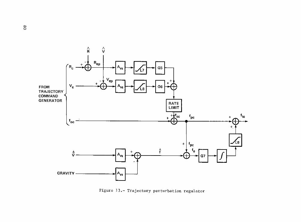
co 0
A A R V
COMMAND GENE RATOR pkJ LIMIT
+ fpc
GRAVITY
Figure 1 3 . - Tra jec to ry p e r t u r b a t i o n r e g u l a t o r

I ------------
I - -( I
I
' I I "C I I I r P
I ) PERTURBATION REGULATOR I _ _ _ - _ _ _ - - - - - _ _ I
I "rc > I A I
" 4 c q , MULT.
Figure 14.- Attitude command generator and perturbation regulator.
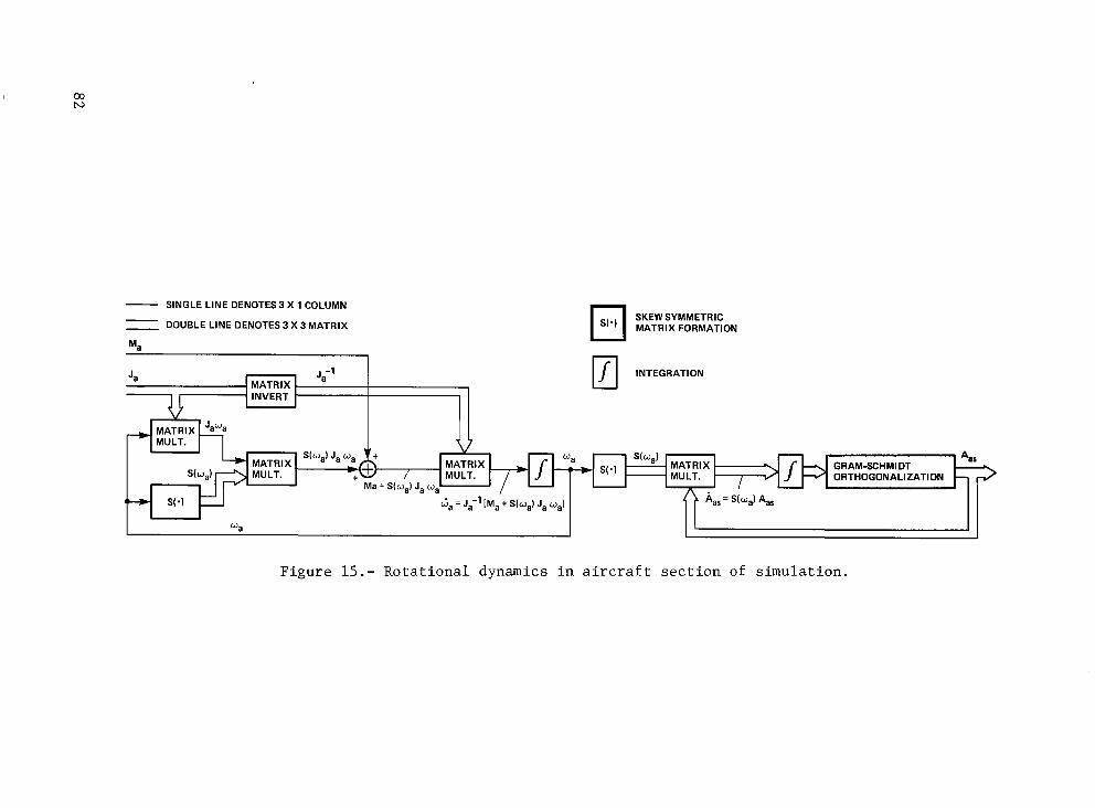
- SINGLE LINE DENOTES 3 X 1 COLUMN = DOUBLE LINE DENOTES 3 X 3 MATRIX
Ma 1
M a t S(w,) J, w,
Ga = J,-l [Ma + S(w,) J, w,l
SKEW SYMMETRIC MATRIX FORMATION
INTEGRATION u
wa
Figure 15.- Rota t iona l dynamics i n a i r c r a f t s e c t i o n of s imula t ion .

. . - .
._ - 8. Performing Organization Report No.
A-7801 - . . - - - . . .
10. Work Unit No.
505-11-41 -
11. Contract or Grant No.
1. Report No. I NASA TP-1512
. _ _ ~ - - ._ - -. . 16. Abstract
The r e s u l t s of a s imula t ion s tudy of an a l t e r n a t i v e design concept f o r an automatic landing- c o n t r o l system a r e presented. a i r c r a f t c a r r i e r .
aerodynamic and propuls ive f o r c e s required r a t h e r than by a convent ional a u t o p i l o t t h a t commands
The concept was appl ied on an A-7E a i r c r a f t approaching a Navy
In t h e a l t e r n a t i v e concept, t h e a i r c r a f t t r a j e c t o r y is d i r e c t l y con t ro l l ed by commanding t h e
2. Government Accession No. I
~ a i r c r a f t a t t i t u d e t o minimize t r a j e c t o r y e r r o r s . Furthermore, t h e dynamic t r i m concept a l lows a s i n g l e conf igu ra t ion t o func t ion over t h e complete f l i g h t envelope without t h e ga in schedul ing o r conf igu ra t ion switching t h a t is employed i n convent ional systems based on p e r t u r b a t i o n s about a number of d i f f e r e n t s t a t i c trim p o i n t s . c o n t r o l system," o r TAFCOS. TAFCOS i s e s s e n t i a l l y an open-loop, feed-forward system t h a t commands t h e proper instantaneous t h r u s t , a n g l e of a t t a c k , and r o l l ang le t o achieve t h e f o r c e s r equ i r ed t o fol low t h e des i r ed t r a j e c t o r y . These dynamic t r i m cond i t ions a r e determined by an inve r s ion of t h e a i r c r a f t non l inea r f o r c e c h a r a c t e r i s t i c s t o c a l c u l a t e t h e r equ i r ed angle of a t t a c k , r o l l ang le , and t h r o t t l e s e t t i n g .
A n explanat ion of implementation d e t a i l s w i th an a i rbo rne d i g i t a l computer i s given. Res t a r e presented t h a t show two-to-one improvement i n touchdown p o i n t d i s p e r s i o n over t h e p re sen t l ) ope ra t iona l automatic ca r r i e r - l and ing system. Fur the r , r e s u l t s show e x c e l l e n t performance over t h e e n t i r e approach p r o f i l e i n t h e presence of s eve re gus t d i s tu rbances .
The des ign concept i s c a l l e d a " t o t a l a i r c r a f t f l i g h t
4. Title and Subtitle
APPLICATION OF THE CONCEPT OF DYNAMIC TRIM CONTROL TO AUTOMATIC LANDING OF CARRIER AIRCRAFT
____. - ._ - 7. Author(s)
G. Allan Smith and George Meyer
9. Performing Organization Name and Address
Ames Research Center, NASA Moffet t F i e l d , C a l i f . 94035
- - 12. Sponsoring Agency Name and Address
National Aeronautics and Space Adminis t ra t ion, Washington, D.C. 20546
19. Security Classif. (of this report)
Unclas s i f i ed
15. Supplementary Notes
20. Security Classif. (of this page)
$6.00 Unclassif ied . - ---
. - .- . - - - . .
3. Recipient's Catalog No.
_ _ _ ... - - 5. Report Date
A p r i l 1980 6. Performing Organization Code
.. - 13. Type of Report and Pkiod Covered
Technical Paper
14. Sponsoring Agency Code -. .
17. Key Words (Suggested ..by Author(s) )
A i r c r a f t s t a b i l i t y Control Autopi lot
~__ . . - -. -~ - 10. Distribution Statement
Unclas s i f i ed - Unlimited
STAR Category - 08
*For sale by the National Technical Information Service, Springfield, Virginia 22161 NASA-Langl ey, 1980

National Aeronautics and Space Administration
Washington, D.C. 20546
THIRD-CLASS BULK RATE Postage and Fees Paid National Aeronautics and Space Administration NASA451
Official Business Penalty for Private Use, $300
1 1 1 U , A , 022980 S00903DS DEPT OF THE AIR FORCE A F WEBPOIlNS LABORATORY ATT??: TECHNICAL LIBBARY {SUL) K T R T L A N D AFB N M 87117
POSTMASTER: If Undeliverable (Section 158 '
Postal Manual) Do Not Return
- ............. ..... . . . . . . . . . . . I . ............ - , I