application of power electronics on hydropower generation
TRANSCRIPT

Journal of Physics Conference Series
PAPER bull OPEN ACCESS
Application of Power Electronics on HydropowerGenerationTo cite this article Johann Hell 2017 J Phys Conf Ser 813 012003
View the article online for updates and enhancements
Related contentTalking Renewables Principles ofrenewable energy technologiesmdashbiomassand hydropowerA Singh
-
Cryogenic power electronics at megawatt-scale using a new type of press-pack IGBTL Graber M Saeedifard M J Mauger et al
-
Laser Power Multiplication in a ParametricFrequency Converter with a CavityDumperMitsumori Tanimoto Akira Yaoita YujiMatsumoto et al
-
Recent citationsAdvantage of variable-speed pumpedstorage plants for mitigating wind powervariations Integrated modelling andperformance assessmentWeijia Yang and Jiandong Yang
-
This content was downloaded from IP address 6521228167 on 03102021 at 1917
Application of Power Electronics on Hydropower Generation
Johann Hell
ANDRITZ HYDRO GmbH Vienna AustriaE-mail JohannHellandritzcom
Abstract The developments in power electronics are offering new opportunities in operation of hydro power generating units The applied load in pump and turbine operation cannot be changed easily By using of frequency converters the speed of the units can be changed in a defined range without losing much efficiency An additional benefit of such kind of concept is the improved transient performance of the entire system In the presented paper the advantage of speed variable power generating system equipped with frequency converters are shown
1 Classical concepts in Hydro power GenerationElectrical Power Systems are operating with a 3-phase alternating current (AC) system with 50Hz or 60Hz The synchronous speed is defined by the system frequency and the number of poles of the motorgenerator In most of the generation applications the prime mover is direct coupled with the generator For very high or very low rotational speed of the turbine a gear box will be used So the size of the generator can be reduced but on the other hand the efficiency will be reduced and maintenance costs of the unit are increased In general AC generating units have to provide active power for balancing of production and consumption and reactive power for voltage stability
11 Electric Machine conceptsDepending on the application different types of electrical machines are used in hydro power generation For all machines the active power flow only can be controlled by the turbine
The electrical machine concepts are also different in the amount of provided Inertia This can be important when special requirements from the Network Code (NC) must be fulfilled
111 Synchronous machinesThis type of machine in used in 99 of all the power generating systems In the classical concept the reactive power can be controlled by variation of the excitation voltage The excitation current can be transferred by slip-rings to the rotor or brushless exciters can be used
For transient system stabilization a Power System Stabilizer (PSS) can be used By measuring speed and electrical power and additional damping torque will be provided for an active stabilization of the units In most of the Network Codes this additional control function is mandatory
For small units in special applications permanent excited machines can be used Because of missing control of reactive power flow the application of this option must be confirmed by the Transmission System Operator (TSO)
1
Hyperbole IOP PublishingIOP Conf Series Journal of Physics Conf Series 813 (2017) 012003 doi1010881742-65968131012003
International Conference on Recent Trends in Physics 2016 (ICRTP2016) IOP PublishingJournal of Physics Conference Series 755 (2016) 011001 doi1010881742-65967551011001
Content from this work may be used under the terms of the Creative Commons Attribution 30 licence Any further distributionof this work must maintain attribution to the author(s) and the title of the work journal citation and DOI
Published under licence by IOP Publishing Ltd
112 Asynchronous MachinesThis type of machine is characterized by a very simple and robust design On the other hand these units cannot supply reactive power to the grid For that purpose additional electrical components (reactive power compensation) must be installed
113 Asynchronous Machines with slip-ringsFor special applications the rotor of the machine can be equipped with a 3 ndashphase winding system which is connected to 3 slip-rings This type of machines together with a converter in the rotor circuitnowadays is used for variable speed hydro power generation A detailed description of this system can be found in chapter 31 below
12 Requirements for Grid ConnectionFor grid connection each generating units has to fulfill different requirements defined in the Network Code of the TSO
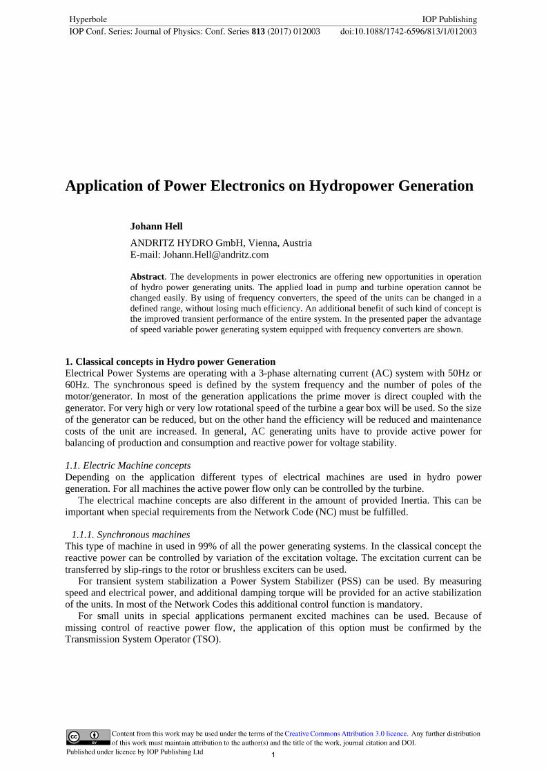
All the parameters of the generating units (voltage and frequency variation) are defined on the network connection point ndash Point of Common Coupling (PCC) The main requirements are voltage and frequency variation reactive power capability frequency regulation capability and transient stability The last point is most critical especially for units with low inertia (eg Bulb type Hydro units or gas-turbine driven units) In Figure 1 below the rotor-angle as a function of the inertia constant H following a 150ms grid disturbance is shown
Figure 1 Diagrams showing transient stability on a grid fault with clearing time of 150ms and different Inertia H
The normalized energy of the rotating mass is expressed in the Inertia constant H measured in MWsMVA
Units with low inertia are not able to fulfill the transient stability requirements
The maximal fault clearing time will be defined by the TSO and is in Central Europe 150ms This time can be different in other regions of the world
2 Power ElectronicsThe ongoing development in power electronic switching devices enables now to design and build converters in the multi-Megawatt range Devices like IGBT IGCT and IEGT from different supplier are available for voltages up to 8000Volts and 4000Amps The used converter topologies are different depending on supplier All the offered solutions have an excellent transient performance and a high efficiency
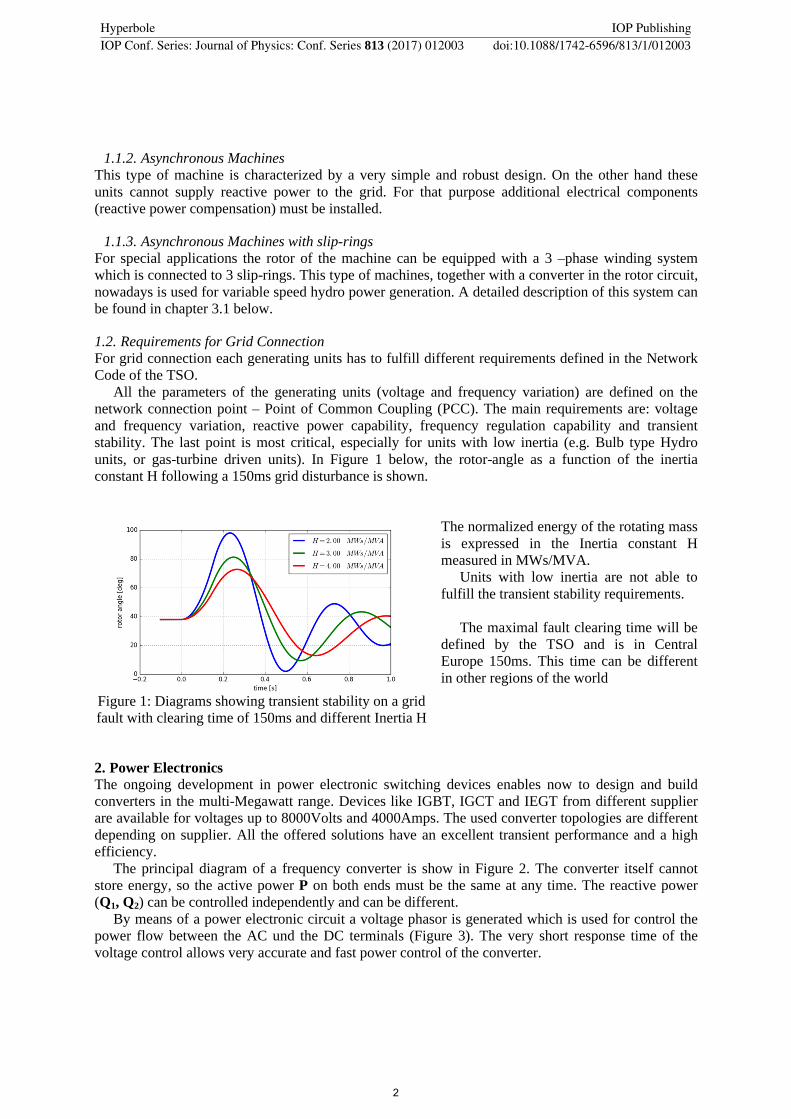
The principal diagram of a frequency converter is show in Figure 2 The converter itself cannot store energy so the active power P on both ends must be the same at any time The reactive power (Q1 Q2) can be controlled independently and can be different
By means of a power electronic circuit a voltage phasor is generated which is used for control the power flow between the AC und the DC terminals (Figure 3) The very short response time of the voltage control allows very accurate and fast power control of the converter
2
Hyperbole IOP PublishingIOP Conf Series Journal of Physics Conf Series 813 (2017) 012003 doi1010881742-65968131012003
Figure 2 Principal diagram of a Full Size Frequency Converter Figure 3 Voltage phasor used for power control
21 Classical Three-Level converterThis type of converter is mainly used in drive application for low voltage as well as in medium voltage applications The shape of the phase voltage of such kind of converter is shown in Figure 4 on the left diagram
22 Multi-level converterThis converter topology will also be used for High Voltage Direct Current (HVDC) power transmission Hereby identical power electronic modules are connected in series so high output voltages (some 100kVrsquos) can be achieved The same modules can also be used in application for power generation for voltages up 20kV For operation at frequencies lower than 15Hz the output current must be reduced
In Hydro Power generation this restriction does not limit the application of the converter because of the speed operating range of a hydro turbine is small and the frequency can be defined by choosing the number of poles of the generator
Figure 4 Shape of Phase-Voltage of 3-level (left) and Multi-level converter (right)
3 Variable speed concepts for Hydro Power GenerationBased on the machine and the converter technology different concepts for variable speed power generation systems are possible In the following paragraphs an example for a variable speed unit with a rated output of 420MVA is presented
3
Hyperbole IOP PublishingIOP Conf Series Journal of Physics Conf Series 813 (2017) 012003 doi1010881742-65968131012003
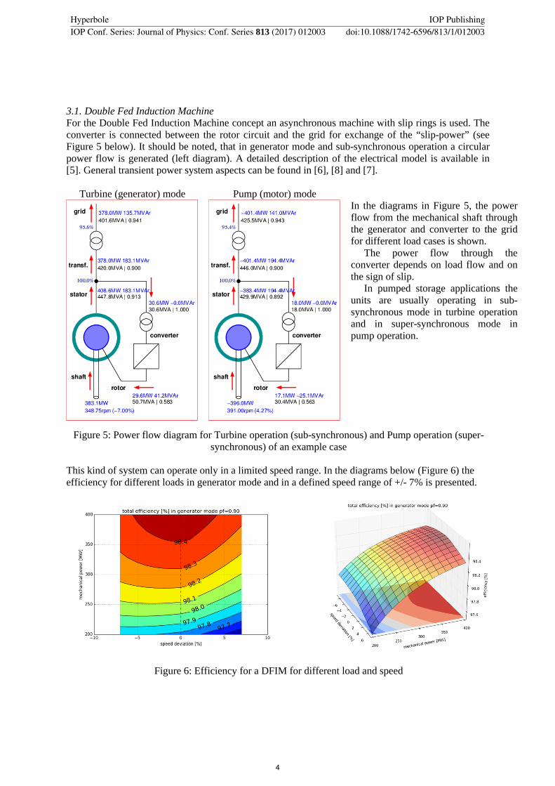
31 Double Fed Induction MachineFor the Double Fed Induction Machine concept an asynchronous machine with slip rings is used The converter is connected between the rotor circuit and the grid for exchange of the ldquoslip-powerrdquo (see Figure 5 below) It should be noted that in generator mode and sub-synchronous operation a circular power flow is generated (left diagram) A detailed description of the electrical model is available in [5] General transient power system aspects can be found in [6] [8] and [7]
Turbine (generator) mode Pump (motor) modeIn the diagrams in Figure 5 the power flow from the mechanical shaft through the generator and converter to the grid for different load cases is shown
The power flow through the converter depends on load flow and on the sign of slip
In pumped storage applications the units are usually operating in sub-synchronous mode in turbine operation and in super-synchronous mode in pump operation
Figure 5 Power flow diagram for Turbine operation (sub-synchronous) and Pump operation (super-synchronous) of an example case
This kind of system can operate only in a limited speed range In the diagrams below (Figure 6) the efficiency for different loads in generator mode and in a defined speed range of +- 7 is presented
Figure 6 Efficiency for a DFIM for different load and speed
4
Hyperbole IOP PublishingIOP Conf Series Journal of Physics Conf Series 813 (2017) 012003 doi1010881742-65968131012003
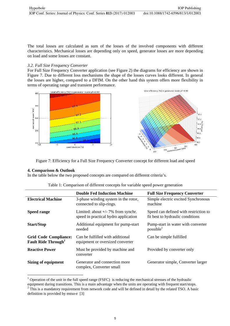
The total losses are calculated as sum of the losses of the involved components with different characteristics Mechanical losses are depending only on speed generator losses are more depending on load and some losses are constant
32 Full Size Frequency ConverterFor Full Size Frequency Converter application (see Figure 2) the diagrams for efficiency are shown in Figure 7 Due to different loss mechanisms the shape of the losses curves looks different In general the losses are higher compared to a DFIM On the other hand this system offers more flexibility in terms of operating range and transient performance
Figure 7 Efficiency for a Full Size Frequency Converter concept for different load and speed
4 Comparison amp OutlookIn the table below the two proposed concepts are compared on different criteriarsquos
Table 1 Comparison of different concepts for variable speed power generation
Double Fed Induction Machine Full Size Frequency Converter
Electrical Machine 3-phase winding system in the rotor connected to slip-rings
Simple electric excited Synchronous machine
Speed range Limited about +- 7 from synchrspeed in practical hydro application
Speed can defined with restriction to fit best to hydraulic conditions
StartStop Additional equipment for pump-start needed
Pump-start in water with converter possible1
Grid Code Compliance Fault Ride Through2
Can be fulfilled with additional equipment or oversized converter
Can be simple fulfilled
Reactive Power Must be provided by machine and converter
Provided by converter only
Sizing of equipment Generator and connection more complex Converter small
Generator simple Converter larger
1
Operation of the unit in the full speed range (FSFC) is reducing the mechanical stresses of the hydraulic equipment during transitions This is a main advantage when the units are operating with frequent startstops2
This is a mandatory requirement from network code and will be defined in detail by the related TSO A basic definition is provided by entso-e [3]
5
Hyperbole IOP PublishingIOP Conf Series Journal of Physics Conf Series 813 (2017) 012003 doi1010881742-65968131012003
Both of the proposed concepts are showing major improvements in hydro power generation bybull Extension of operating range andbull Improving the transient performance
The drawback of installation of additional power electronic equipment with higher losses will be compensated by higher flexibility which becomes more important in the future Due to future developments in power electronics reduction in cost and size of the converters can be expected
5 Bibliography[1] J Hell Grid Frequency Response ndash Contribution of Hydro-Power for Grid Stabilization
HYDRO conference Cernobbio 2014[2] HYPERBOLE project EU FP7-ENERGY-2013-1 Grant 608532
web httpshyperboleepflchSitePagesHomeaspx[3] ENTSO-E Network Code for Requirements for Grid Connection Applicable to all Generators
ENTSO-E Brussels Belgium March 2013[4] M Matos Fernandes ldquoConnection of the First Pump ndash Storage Variable Speed Machines in
Portugal TSO Main Requirementsrdquo 11th Intrsquol Workshop on Large-Scale Integration of Wind Power and on Transmission Networks for Offshore Wind Power Plants November 2012
[5] Argonne National Laboratory Modelling Adjustable Speed Pumped Storage Hydro Units Employing Doubly-Fed Induction Machine ANLDIS-1306 available in httpwwwdisanlgovprojectspshANL_DIS-13_06_Modeling_AS_PSHpdf
[6] P Kundur Power System Stability and Control McGraw-Hill Education 1994 ISBN 9780070359581
[7] F Rodriguez P Ledamsa Simplified wind generator model for Transmission System Operator planning studies 7th International Workshop on large scale integration of Wind Power and on Transmission Networks of Offshore Wind farms
[8] JMachowski JW Bialek Power System Dynamics ndash Stability and Control John Wiley amp Sons 2008
6 AcknowledgmentsThe research leading to the results published in this paper is part of the HYPERBOLE research project[2] granted by the European Commission (ERCFP7-ENERGY2013-1-Grant 608532)
6
Hyperbole IOP PublishingIOP Conf Series Journal of Physics Conf Series 813 (2017) 012003 doi1010881742-65968131012003
Application of Power Electronics on Hydropower Generation
Johann Hell
ANDRITZ HYDRO GmbH Vienna AustriaE-mail JohannHellandritzcom
Abstract The developments in power electronics are offering new opportunities in operation of hydro power generating units The applied load in pump and turbine operation cannot be changed easily By using of frequency converters the speed of the units can be changed in a defined range without losing much efficiency An additional benefit of such kind of concept is the improved transient performance of the entire system In the presented paper the advantage of speed variable power generating system equipped with frequency converters are shown
1 Classical concepts in Hydro power GenerationElectrical Power Systems are operating with a 3-phase alternating current (AC) system with 50Hz or 60Hz The synchronous speed is defined by the system frequency and the number of poles of the motorgenerator In most of the generation applications the prime mover is direct coupled with the generator For very high or very low rotational speed of the turbine a gear box will be used So the size of the generator can be reduced but on the other hand the efficiency will be reduced and maintenance costs of the unit are increased In general AC generating units have to provide active power for balancing of production and consumption and reactive power for voltage stability
11 Electric Machine conceptsDepending on the application different types of electrical machines are used in hydro power generation For all machines the active power flow only can be controlled by the turbine
The electrical machine concepts are also different in the amount of provided Inertia This can be important when special requirements from the Network Code (NC) must be fulfilled
111 Synchronous machinesThis type of machine in used in 99 of all the power generating systems In the classical concept the reactive power can be controlled by variation of the excitation voltage The excitation current can be transferred by slip-rings to the rotor or brushless exciters can be used
For transient system stabilization a Power System Stabilizer (PSS) can be used By measuring speed and electrical power and additional damping torque will be provided for an active stabilization of the units In most of the Network Codes this additional control function is mandatory
For small units in special applications permanent excited machines can be used Because of missing control of reactive power flow the application of this option must be confirmed by the Transmission System Operator (TSO)
1
Hyperbole IOP PublishingIOP Conf Series Journal of Physics Conf Series 813 (2017) 012003 doi1010881742-65968131012003
International Conference on Recent Trends in Physics 2016 (ICRTP2016) IOP PublishingJournal of Physics Conference Series 755 (2016) 011001 doi1010881742-65967551011001
Content from this work may be used under the terms of the Creative Commons Attribution 30 licence Any further distributionof this work must maintain attribution to the author(s) and the title of the work journal citation and DOI
Published under licence by IOP Publishing Ltd
112 Asynchronous MachinesThis type of machine is characterized by a very simple and robust design On the other hand these units cannot supply reactive power to the grid For that purpose additional electrical components (reactive power compensation) must be installed
113 Asynchronous Machines with slip-ringsFor special applications the rotor of the machine can be equipped with a 3 ndashphase winding system which is connected to 3 slip-rings This type of machines together with a converter in the rotor circuitnowadays is used for variable speed hydro power generation A detailed description of this system can be found in chapter 31 below
12 Requirements for Grid ConnectionFor grid connection each generating units has to fulfill different requirements defined in the Network Code of the TSO
All the parameters of the generating units (voltage and frequency variation) are defined on the network connection point ndash Point of Common Coupling (PCC) The main requirements are voltage and frequency variation reactive power capability frequency regulation capability and transient stability The last point is most critical especially for units with low inertia (eg Bulb type Hydro units or gas-turbine driven units) In Figure 1 below the rotor-angle as a function of the inertia constant H following a 150ms grid disturbance is shown
Figure 1 Diagrams showing transient stability on a grid fault with clearing time of 150ms and different Inertia H
The normalized energy of the rotating mass is expressed in the Inertia constant H measured in MWsMVA
Units with low inertia are not able to fulfill the transient stability requirements
The maximal fault clearing time will be defined by the TSO and is in Central Europe 150ms This time can be different in other regions of the world
2 Power ElectronicsThe ongoing development in power electronic switching devices enables now to design and build converters in the multi-Megawatt range Devices like IGBT IGCT and IEGT from different supplier are available for voltages up to 8000Volts and 4000Amps The used converter topologies are different depending on supplier All the offered solutions have an excellent transient performance and a high efficiency
The principal diagram of a frequency converter is show in Figure 2 The converter itself cannot store energy so the active power P on both ends must be the same at any time The reactive power (Q1 Q2) can be controlled independently and can be different
By means of a power electronic circuit a voltage phasor is generated which is used for control the power flow between the AC und the DC terminals (Figure 3) The very short response time of the voltage control allows very accurate and fast power control of the converter
2
Hyperbole IOP PublishingIOP Conf Series Journal of Physics Conf Series 813 (2017) 012003 doi1010881742-65968131012003
Figure 2 Principal diagram of a Full Size Frequency Converter Figure 3 Voltage phasor used for power control
21 Classical Three-Level converterThis type of converter is mainly used in drive application for low voltage as well as in medium voltage applications The shape of the phase voltage of such kind of converter is shown in Figure 4 on the left diagram
22 Multi-level converterThis converter topology will also be used for High Voltage Direct Current (HVDC) power transmission Hereby identical power electronic modules are connected in series so high output voltages (some 100kVrsquos) can be achieved The same modules can also be used in application for power generation for voltages up 20kV For operation at frequencies lower than 15Hz the output current must be reduced
In Hydro Power generation this restriction does not limit the application of the converter because of the speed operating range of a hydro turbine is small and the frequency can be defined by choosing the number of poles of the generator
Figure 4 Shape of Phase-Voltage of 3-level (left) and Multi-level converter (right)
3 Variable speed concepts for Hydro Power GenerationBased on the machine and the converter technology different concepts for variable speed power generation systems are possible In the following paragraphs an example for a variable speed unit with a rated output of 420MVA is presented
3
Hyperbole IOP PublishingIOP Conf Series Journal of Physics Conf Series 813 (2017) 012003 doi1010881742-65968131012003
31 Double Fed Induction MachineFor the Double Fed Induction Machine concept an asynchronous machine with slip rings is used The converter is connected between the rotor circuit and the grid for exchange of the ldquoslip-powerrdquo (see Figure 5 below) It should be noted that in generator mode and sub-synchronous operation a circular power flow is generated (left diagram) A detailed description of the electrical model is available in [5] General transient power system aspects can be found in [6] [8] and [7]
Turbine (generator) mode Pump (motor) modeIn the diagrams in Figure 5 the power flow from the mechanical shaft through the generator and converter to the grid for different load cases is shown
The power flow through the converter depends on load flow and on the sign of slip
In pumped storage applications the units are usually operating in sub-synchronous mode in turbine operation and in super-synchronous mode in pump operation
Figure 5 Power flow diagram for Turbine operation (sub-synchronous) and Pump operation (super-synchronous) of an example case
This kind of system can operate only in a limited speed range In the diagrams below (Figure 6) the efficiency for different loads in generator mode and in a defined speed range of +- 7 is presented
Figure 6 Efficiency for a DFIM for different load and speed
4
Hyperbole IOP PublishingIOP Conf Series Journal of Physics Conf Series 813 (2017) 012003 doi1010881742-65968131012003
The total losses are calculated as sum of the losses of the involved components with different characteristics Mechanical losses are depending only on speed generator losses are more depending on load and some losses are constant
32 Full Size Frequency ConverterFor Full Size Frequency Converter application (see Figure 2) the diagrams for efficiency are shown in Figure 7 Due to different loss mechanisms the shape of the losses curves looks different In general the losses are higher compared to a DFIM On the other hand this system offers more flexibility in terms of operating range and transient performance
Figure 7 Efficiency for a Full Size Frequency Converter concept for different load and speed
4 Comparison amp OutlookIn the table below the two proposed concepts are compared on different criteriarsquos
Table 1 Comparison of different concepts for variable speed power generation
Double Fed Induction Machine Full Size Frequency Converter
Electrical Machine 3-phase winding system in the rotor connected to slip-rings
Simple electric excited Synchronous machine
Speed range Limited about +- 7 from synchrspeed in practical hydro application
Speed can defined with restriction to fit best to hydraulic conditions
StartStop Additional equipment for pump-start needed
Pump-start in water with converter possible1
Grid Code Compliance Fault Ride Through2
Can be fulfilled with additional equipment or oversized converter
Can be simple fulfilled
Reactive Power Must be provided by machine and converter
Provided by converter only
Sizing of equipment Generator and connection more complex Converter small
Generator simple Converter larger
1
Operation of the unit in the full speed range (FSFC) is reducing the mechanical stresses of the hydraulic equipment during transitions This is a main advantage when the units are operating with frequent startstops2
This is a mandatory requirement from network code and will be defined in detail by the related TSO A basic definition is provided by entso-e [3]
5
Hyperbole IOP PublishingIOP Conf Series Journal of Physics Conf Series 813 (2017) 012003 doi1010881742-65968131012003
Both of the proposed concepts are showing major improvements in hydro power generation bybull Extension of operating range andbull Improving the transient performance
The drawback of installation of additional power electronic equipment with higher losses will be compensated by higher flexibility which becomes more important in the future Due to future developments in power electronics reduction in cost and size of the converters can be expected
5 Bibliography[1] J Hell Grid Frequency Response ndash Contribution of Hydro-Power for Grid Stabilization
HYDRO conference Cernobbio 2014[2] HYPERBOLE project EU FP7-ENERGY-2013-1 Grant 608532
web httpshyperboleepflchSitePagesHomeaspx[3] ENTSO-E Network Code for Requirements for Grid Connection Applicable to all Generators
ENTSO-E Brussels Belgium March 2013[4] M Matos Fernandes ldquoConnection of the First Pump ndash Storage Variable Speed Machines in
Portugal TSO Main Requirementsrdquo 11th Intrsquol Workshop on Large-Scale Integration of Wind Power and on Transmission Networks for Offshore Wind Power Plants November 2012
[5] Argonne National Laboratory Modelling Adjustable Speed Pumped Storage Hydro Units Employing Doubly-Fed Induction Machine ANLDIS-1306 available in httpwwwdisanlgovprojectspshANL_DIS-13_06_Modeling_AS_PSHpdf
[6] P Kundur Power System Stability and Control McGraw-Hill Education 1994 ISBN 9780070359581
[7] F Rodriguez P Ledamsa Simplified wind generator model for Transmission System Operator planning studies 7th International Workshop on large scale integration of Wind Power and on Transmission Networks of Offshore Wind farms
[8] JMachowski JW Bialek Power System Dynamics ndash Stability and Control John Wiley amp Sons 2008
6 AcknowledgmentsThe research leading to the results published in this paper is part of the HYPERBOLE research project[2] granted by the European Commission (ERCFP7-ENERGY2013-1-Grant 608532)
6
Hyperbole IOP PublishingIOP Conf Series Journal of Physics Conf Series 813 (2017) 012003 doi1010881742-65968131012003
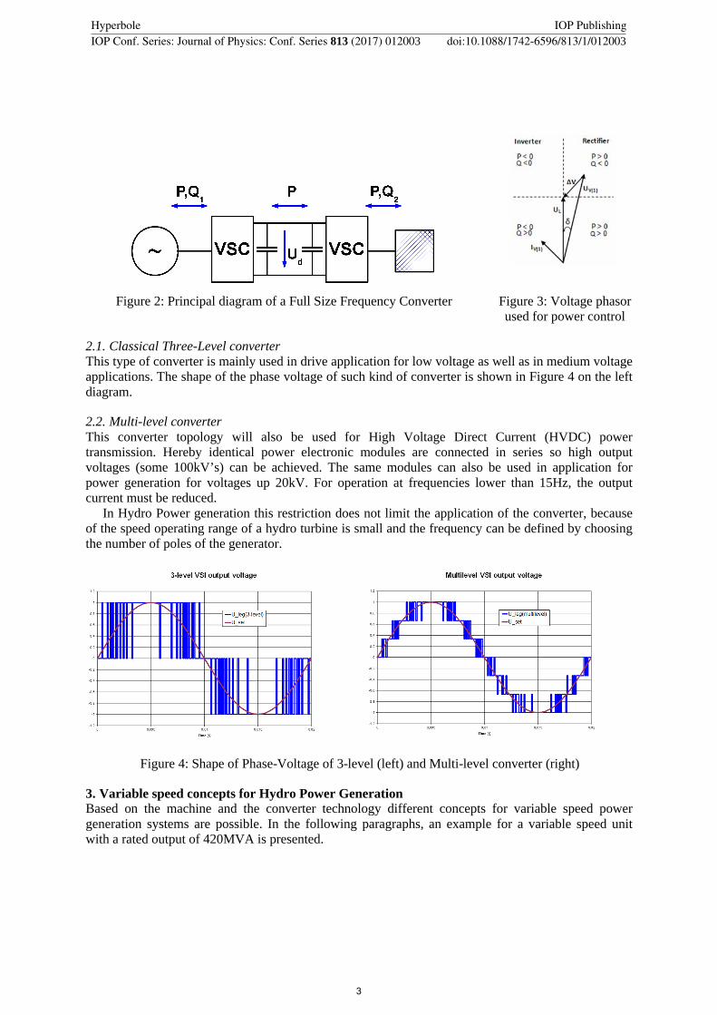