application of mechanical arm systems to reduce injuries
TRANSCRIPT

Application of Mechanical Arm Systems to Reduce Injuries and
Increase Productivity in Shipbuilding
Prepared for:
National Shipbuilding Research Program
Surface Preparation and Coatings Panel (SPC)
Submitted by:
Stephen Cogswell, BAE Systems Southeast Shipyards
Arcino Quiero, Newport News Shipbuilding
Equipois, Inc.
Sharon Huntley, NSRP Workforce Development Panel
June, 2013
Approved for public release; distribution is unlimited.
Category B Data – Government Purpose Rights.

1
Executive Summary
Shipyards continue to be a high risk work environment as defined by OSHA. Recent improvements have helped to reduce some of the work related injuries experienced, but shipbuilding still remains at the top of the list in terms work related injuries. This is primarily due to the physically demanding nature of the work that is done. Heavy tools and repetitive motions lead to eventual accidents and injuries, which incur significant cost over the period of a single ship build.
The matter is further complicated by the ever increasing age of the workforce in ship yards. With the average age now in the mid to late 40’s it is even more pertinent to ensure the workers safety by using proper equipment. Difficult tasks can be made even slower by weakened, older joints and muscles. These injuries lead the excessive absenteeism and low employee morale in shipyards.
This project seeks to aid workers by implementing new equipment that will reduce cost of shipbuilding by reducing injuries and increasing production rates. Additionally, an increase in overall work quality is anticipated.
Equipois’ zeroG® system is a mechanical assisted arm that requires no external power source (e.g. electric, pneumatic or hydraulic). This system can bear the weight of nearly any handheld tool or piece of equipment in the shipyard. This will take the strain off the operator, allowing them to work without the need of additional breaks or work rotations. It is particularly useful with work being done overhead (e.g., grinding), or when the tool has excessive reaction forces (e.g., abrasive blasting or water jetting).
The zeroG® system was demonstrated BAE Systems Southeast Shipyards and Marinette Marine over a variety of different tasks. Small demonstrations were conducted to allow workers to feel how the system operates in a more controlled environment than in a dry dock. Surveys of those who installed and used the systems were conducted to better gauge the opinions about the setup, training and operation of the zeroG® system. Review of the surveys shows that with fairly minimal training, operators can do their job faster and with less fatigue than without the zeroG® system.
In addition to conducting demonstrations, the NSRP effort included collaboration with the Navy Mechanical Assisted Arm Working Group. The working group was investigating the use of similar equipment in Public Shipyards. The collective effort shows that mechanical arms have value in situations that require workers to operate a tool weighing in excess of ten pounds for sustained durations; or use tools overhead, with arms outstretched, or in any other poor ergonomic positions, for periods of an hour or more.

2
Acknowledgements
A special acknowledgement would like to be made to those organizations that assisted in the project including JLG Industries Inc., Flow International Corporation, Marinette Marine Corporation, Equipois Inc., BAE Systems and Naval Sea Systems Command. In addition, the project was able to leverage the work of others through collaboration with the Navy’s Mechanical Assisted Arm Working Group – Navy Safety Liaison Office, NAVSEA 04X, four Naval Shipyard Safety and Waterfront Representatives, Equipois representatives, Navy Surface Warfare Center – Carderock and National Institute of Occupational Safety and Health.

3
Table of Contents
Executive Summary ....................................................................................................................................... 1
Acknowledgements ....................................................................................................................................... 2
Conclusions ................................................................................................................................................... 4
Recommendations ........................................................................................................................................ 5
Project Objectives and Methodologies ......................................................................................................... 6
Task 1 – Survey Industry for mechanical arms...................................................................................... 6
Task 2 – Accomplish Shipyard testing of a mechanical arm ................................................................. 6
Task 3 – Develop Shipyard Implementation Strategy ........................................................................... 7
Task 4 – Presentation of Findings ......................................................................................................... 7
Background ................................................................................................................................................... 8
Industry Survey ......................................................................................................................................... 8
Aging Shipyard Workforce ...................................................................................................................... 11
NSRP Project Efforts .................................................................................................................................... 13
NSRP Shipyard Demonstrations .............................................................................................................. 13
Water jet demonstration, BAE Systems Southeast Shipyards ............................................................ 13
Grinding demonstration BAE Systems Southeast Shipyards .............................................................. 15
Abrasive blast demonstration Marinette Marine Corporation........................................................... 16
Project Cooperation with Mechanical Assisted Arm Working Group ..................................................... 17
Technology Transfer ............................................................................................................................... 19
Discussion.................................................................................................................................................... 20
Reducing Costs Due to Injuries in the Shipyard ...................................................................................... 20
Increased Production Rate and Work Quality ........................................................................................ 20
Survey Results ......................................................................................................................................... 20
Appendix A .................................................................................................................................................. 22
Appendix B .................................................................................................................................................. 23
Appendix C .................................................................................................................................................. 24
Technology Transfer Report: ...................................................................................................................... 24

4
Conclusions
The project demonstrated that mechanical assisted arms can be useful in a shipyard environment. Case studies and field demonstrations have led to the following conclusions.
1. Workplace injuries can be reduced and possibly even eliminated when a mechanical arm is used for jobs that require workers to operate a tool weighing in excess of ten pounds for sustained durations; or use tools overhead, with arms outstretched, or in any other poor ergonomic positions, for periods of an hour or more.
2. Reduced fatigue from tool operation can be directly linked to improved productivity and quality of work.
3. It is important to realize that although the mechanical arm is designed to make the jobs easier, it is only as useful as the training the employees were given. When trained properly the mechanical arm was beneficial for strenuous tasks in the shipyard.
4. Employees showed continuously increased comfort and efficiency as time using the arm progressed. User surveys conducted at later shifts in the demonstrations had higher overall ratings.
5. One arm and mounting stand can be used for multiple applications. A more permanent application for the arm may dictate a custom designed mounting stand. This is easily accomplished with the assistance of the manufacturer. In this study, all of the initial mounting stand designs was completed remotely. One site visit was required to fine-tune the installation.

5
Recommendations
1. It is advised that mechanical arm technology be implemented for the highest-risk eligible shipyard operations. These include: • Grinding, especially in overhead positions • Water jet operation • Abrasive Blasting • Reciprocating saw • Heat Induction • Other high-risk operations that could benefit from these technologies
2. Certain applications require greater worker mobility. Examples include grinding welds over long
distance. Team members have developed proposals for mobile versions of the zeroG technology, including versions mounted to exoskeletal legs and to small motorized carts. It is recommended that NSRP continue to explore these solutions and consider development funding.
3. Versions of mechanical arm technology are under development that would allow workers to “pick and place” materials. Material transport is a significant ergonomic challenge throughout shipyards. While solutions exist for very heavy payloads, such as forklifts and cranes, there is a need for a device that will allow workers to move payloads of up to 150 lbs. in a wide range of environments where fixed devices are impracticable or cost prohibitive.

6
Project Objectives and Methodologies
The goal of this project is to reduce costs by eliminating injuries and increasing productivity in shipyards through the use of mechanical arm systems. This project supports reduction of total ownership costs (TOC) initiatives by reducing injury rates, improving productivity and improving quality. The use of heavy hand-held tools is common to the shipbuilding process. Use of these heavy tools, such as grinders, needle guns and water jet hand lances place considerable musculoskeletal stress on the user. Shipyards are realizing increasing injury rates, as well as absenteeism, morale problems, and other collateral issues associated with the physical work.
The first objective will be to collect data on the effects of mechanical arm systems in designated production areas in a shipyard. Although mechanical arm systems have already achieved Technology Readiness Level 91 status, testing will validate changes in injury rates, labor productivity, tool damage and absenteeism associated with implementation of mechanical arm systems.
The project was broken into four unique tasks. Each task has produced a deliverable that will lead into the final product. The tasks are as follows.
Task 1 – Survey Industry for mechanical arms
The project has completed a survey of available mechanical arms and completed a comparison including range of motion, weight, functionality and cost.
Task 2 – Accomplish Shipyard testing of a mechanical arm
• Design and ship a mechanical arm system with the appropriate equipment needed to support up to three specific applications: overhead grinding; water jet hand lance application; and sandblasting. Alternative mounting solutions (gimbals) may be required for the project. Attachment to an aerial platform shall not be accomplished without written permission from the manufacturer of the platform.
• Provide complete installation, training and interviews at BAE Systems SSYI and Fincantieri Marinette Marine facilities.
• Conduct interviews with risk management, manufacturing operations, and others to help identify and prioritize those operational uses with highest payback to the business.
• Provide extended data collection in each application both pre- and post- installation of the mechanical arm system.
1 Technology Readiness Level (TRL) is a measure used to assess the maturity of evolving technologies during its development and in some cases during early operations. The TRL scale is from “0” (Basic principles observed and reported) to “9” (Actual system proven through successful mission operations).

7
Task 3 – Develop Shipyard Implementation Strategy
This portion of the project will be led by the Work Force Development Panel. Based on the results of the shipyard trials we will develop an implementation plan for where the arm might be used and how to instruct the workforce in job selection and application of the arm.
Task 4 – Presentation of Findings
At all SPC meetings, he project team will present our findings and recommendations, including technical backup data. The project team will interface with the Navy’s Mechanical Assisted Arm Working Group.

8
Background
Industry Survey
As part of the Task 1 requirements an industry survey was conducted of currently available mechanical arms. Following is a summary of information on the products surveyed
Equipois – zeroG system (www.Equipoisinc.com)
10 degrees of freedom or more
12 to 110 inch lateral reach.
Low to Medium Payloads: 3 to 50 lbs
Fully dynamic response with articulation allowing full freedom of motion for
most tasks
Fully portable – can be cart mounted, floor mounted or overhead mounted –
approx. weight 10 lbs.
No electric, pneumatic or hydraulic power required.
$4,000 to $12,000
Positech Manipulator Arms – Articulated Jib Booms, Lode Arm, Reaction Arm (shown), Simple Air Manipulator (www.positech-solutions.com)
4 to 6 degrees of freedom
41 to 120 inches lateral reach for smaller jib arms.
6 to 12 meter for larger crane systems.
Medium to High Payloads 35 to 5,000 lbs
Traditional floor mount post with articulating jib or pneumatic lifting arm. Typically used with larger parts and payloads. Reinforced floor mount – approx weight 150 to 600 lbs. Torque arms for large tools with limited degrees of freedom. Requires pneumatic or hydraulic power.
$5,000 to $8,000

9
Midwest Specialties, Inc. – Flex Arm (www.flexarminc.com)
Up to 5 degrees of freedom
11 to 84 inch lateral reach
Low to Medium Payloads: 5 to 80 lbs
Designed as torque reaction arm, so provides limited freedom of motion. Best for torque tools, drilling and tapping tools Portable – can be mounted to carts, floor or structural mount – approx. weight 35 to 100 lbs No electric, pneumatic or hydraulic power required.
$2,000 to $6,000
Gorbel – Easy Arm, G Force (www.gorbel.com)
4 to 6 degrees of freedom
6 to 14 feet lateral reach Low to High Payloads:
0 to 330 lbs
Traditional floor mount post with articulating jib or pneumatic/electric lifting arm. Typically used with larger parts and payloads but also used with tools Intelligent lift capability – controls to allow for powered motion Floor or overhead mount – approx weight 150 to 600 lbs Requires pneumatic or electric power.
$6,000 to $12,000

10
Technospiro Machine Tool S.L. - 3Arm (www.articulatedarm.com)
Up to 6 degrees of freedom
45 to 77 inch lateral reach Low to Medium Payloads: 10 to 77 lbs
Originally designed for tapping tools. Has limited freedom of motion. Lockable joints. End effectors for some drilling, tapping, grinding and sanding tools Portable – can be mounted to carts, floor mounted or overhead mounted – approx. weight 75 lbs. No electric, pneumatic or hydraulic power required
$6,000 to $8,000
Ingersoll-Rand Productivity Solutions – Arm Systems, Articulating Jibs (www.irco.com)
4 to 5 degrees of freedom
4 to 8 feet lateral reach for smaller jib arms.
Medium to High Payloads: 35 to 500 lbs
Traditional floor mount post with articulating jib or pneumatic lifting arm. Typically used with larger parts and payloads. Reinforced floor mount – approx weight 150 to 600 lbs. Requires pneumatic or hydraulic power.
$5,000 to $8,000
Advanced Manipulator Specialists, Inc. (www.advancedmanipulator.com)
4 to 5 degrees of freedom
4 to 8 feet lateral reach
Medium to High Payloads:10 to 300 lbs
Traditional floor mount post with articulating jib or pneumatic lifting arm. Torque arm for tools with limited degrees of freedom. Reinforced floor mount – approx weight 150 to 600 lbs. Requires pneumatic or hydraulic power.
$5,000 to $8,000

11
During the industry wide survey of mechanical arms the zeroG® arm was determined to be the most suited for this shipyard demonstration. Although the price of the zeroG® can vary slightly higher than some of the other products reviewed, it makes up for that in its abilities. It has the highest load capacity of any mechanical arms not requiring electrical, pneumatic or hydraulic power. The load capacity makes it feasible for many different tasks, while the lack of required power makes it more portable. No major changes to the shipyard are required to accommodate its use (e.g. addition of power or hydraulic lines) and it can be easily moved as the operator is required to move, because ships are not typically built on assembly lines. The zeroG® arm technology was developed by Equipois in collaboration with Garrett Brown, inventor of the award-winning Steadicam camera stabilization system. Equipois worked with private industry, including top manufacturers such as Boeing, Ford, General Electric, John Deere and Caterpillar to develop the zeroG® technology for a range of industrial applications. In the approximately six years since zeroG® was introduced, the technology has significantly reduced workplace injuries and increased productivity for aerospace, defense, automotive, heavy machinery, and other manufacturing industries. Government customers such as the Navy’s Fleet Readiness Centers have also begun adopting zeroG® arms for their maintenance and repair operations.
Equipois has worked with its customers to document the benefits of the technology through case studies. For example, a case study for grinding conducted within the foundry industry showed a reduction in task time of approximately 60%, reduction in absenteeism of approximately 50%, and reduction of injuries to zero, as well as an increase in employee morale. The annual ROI for the technology was reported by the company to be 583% per year with a payback period of 0.17 months. Similarly, Equipois reported that a case study for drilling with a major aerospace manufacturer yielded an annual ROI of 366% from reduction of injuries and productivity improvements.
For this NSRP project, Equipois worked with BAE Systems to develop a mounting solution that allowed the zeroG® arm to attach to a man lift and maneuver freely within the work envelope. The manufacturer of the personnel lift and the manufacturer of the water jet provided their written approval for attachment of the zeroG® system to their equipment.
The zeroG® system requires very little initial set up and be easily disassembled and relocated to the next job location in a matter of several minutes. They also have a low cost of maintenance do to the simplistic design that requires no hydraulic fluid and no maintenance like a pneumatic system. Simple inspections of the moving components are conducted monthly or sometimes only annually.
Aging Shipyard Workforce
Based on OSHA studies, shipbuilding has one of the highest injury rates in all of American work industries. Recent improvements have helped to reduce some of the injuries, but they are still well above the industry average. There are two dominant causes for this high injury rate. First, the work is, by nature physically demanding which can lead to injury. Secondly, the aging work force becomes more prone to injury after years of repetitive motion. With the national average age in a shipyard being 49,

12
many of these employees have been doing their jobs for upwards of 30 years. Conducting operations such as overhead grinding for 30 years can lead to chronic muscle, tendon and nerve issues. Chronic injuries can spring an increase in absenteeism as well worker compensation costs. Unfortunately, as the workforce ages there is typically a decrease in stamina. A decrease in stamina leads to more resting, which although helps prevent injury, is cost and time prohibitive on projects. With the average age ever increasing it is important that the employees are protected to avoid these injuries. Mechanical assisted arms allow the strain to be removed from the muscle, leading to a reduction or even elimination work injury cases and an increase in productivity rate while completing those tasks.

13
NSRP Project Efforts
NSRP Shipyard Demonstrations
Water jet demonstration, BAE Systems Southeast Shipyards
For this demonstration, a mounting stand for a mechanical arm was designed and installed in a JLG high reach. Figure 1 shows the mounting stand design drawing. Both equipment manufacturers were involved in the design process. JLG reviewed design engineering drawings for the mounting stand and provided written approval for the installation into their equipment. Flow International provided an A-3000 Jet Lance to Equipois for integration of the gimbal to the lance. The lance and gimbal were returned the Flow International where their design engineering department provided written approval for the installation of the zeroG arm gimbal to the A-3000 Jet Lance. Figure 2 and Figure 3 shows the water jet lance attached to the zeroG® system.
Equipois, Flow, and BAE conducted a two-day demonstration on a US Navy surface combatant. Two operators were observed using the arm while water jetting from an elevated platform for both days. The system was left in place on the project and utilized by the following shifts until project completion. Operators’ comments provided feedback on ease of motion, fatigue, productivity, ergonomics and production. Results varied, typically dependent on the angle in which the work was being conducted. It was found that anywhere they had to hold the water jet lance in an overhead position the zeroG® arm made the work much easier. Mixed opinions were found when the zeroG® was used for a work surface that was at 90 degrees or less to the operator’s torso. It was estimated that the arm took 100% of the weight of the lance and about 50% of the back thrust of the water jet lance. We found that the surveys became more favorable over time. In other words as the operators became more accustomed to the arm they learned how to finesse its movement to their body language.
Figure 1. Personnel Lift Based zeroG Water Jet

14
Figure 2. Water Jet Lance Attached to zeroG System
Figure 3. Water Jet Lance on Man Lift

15
Grinding demonstration BAE Systems Southeast Shipyards
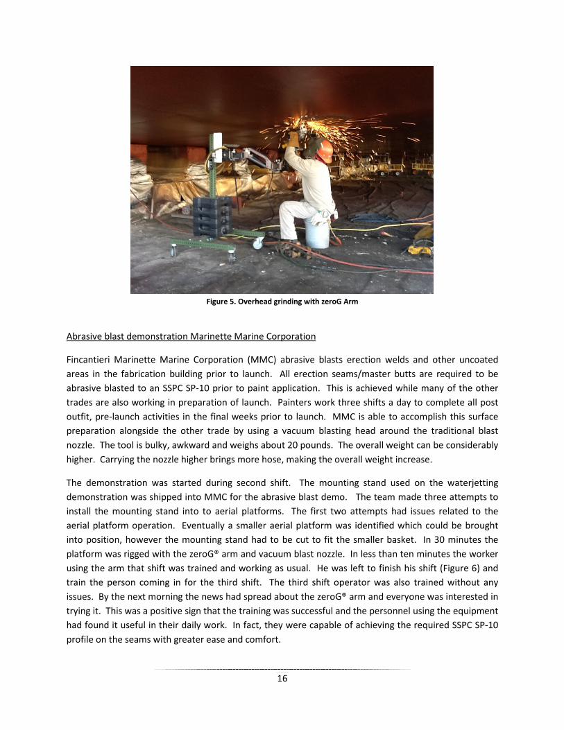
The Center for Disease Control has stated that “Grinding material overhead puts workers in poor posture for neck, shoulders and arms possibly resulting in musculoskeletal disorders.”2 It was especially important that this activity was extensively studied. Therefore, the zeroG® arm was used in a variety of different grinding tasks to see performance across the entire shipyard. The most successful was the overhead grinding and welding operations during the opening of access holes of the vessels underwater hulls. Additionally, two work stations were set up inside the fabrication shop to evaluate employee opinions for both when the zeroG® arm was used and when it was not used. When the work surface was waist high or lower, most employees preferred not to use the zeroG®, because most of the weight of the tool was taken by the work surface. Anywhere the operation required the employee to take the weight of the tool onto their muscles (typically above waist high) while grinding they preferred to use the zeroG® arm. Figure 4 and Figure 5 show examples of overhead grinding without and with the zeroG® system, respectively.
Figure 4. Overhead Grinding without zeroG Arm
2 Center for Disease Control, Ergonomic Interventions in Shipyards, 2012 (http://www.cdc.gov/niosh/topics/ergonomics/ergship/grinding.html).
16
Figure 5. Overhead grinding with zeroG Arm
Abrasive blast demonstration Marinette Marine Corporation
Fincantieri Marinette Marine Corporation (MMC) abrasive blasts erection welds and other uncoated areas in the fabrication building prior to launch. All erection seams/master butts are required to be abrasive blasted to an SSPC SP-10 prior to paint application. This is achieved while many of the other trades are also working in preparation of launch. Painters work three shifts a day to complete all post outfit, pre-launch activities in the final weeks prior to launch. MMC is able to accomplish this surface preparation alongside the other trade by using a vacuum blasting head around the traditional blast nozzle. The tool is bulky, awkward and weighs about 20 pounds. The overall weight can be considerably higher. Carrying the nozzle higher brings more hose, making the overall weight increase.
The demonstration was started during second shift. The mounting stand used on the waterjetting demonstration was shipped into MMC for the abrasive blast demo. The team made three attempts to install the mounting stand into to aerial platforms. The first two attempts had issues related to the aerial platform operation. Eventually a smaller aerial platform was identified which could be brought into position, however the mounting stand had to be cut to fit the smaller basket. In 30 minutes the platform was rigged with the zeroG® arm and vacuum blast nozzle. In less than ten minutes the worker using the arm that shift was trained and working as usual. He was left to finish his shift (Figure 6) and train the person coming in for the third shift. The third shift operator was also trained without any issues. By the next morning the news had spread about the zeroG® arm and everyone was interested in trying it. This was a positive sign that the training was successful and the personnel using the equipment had found it useful in their daily work. In fact, they were capable of achieving the required SSPC SP-10 profile on the seams with greater ease and comfort.

17
Figure 6. Abrasive blasting using zeroG System
Project Cooperation with Mechanical Assisted Arm Working Group
As part of this NSRP project the team participated in the Navy’s Mechanical Assisted Arm Working Group. The working group is formed by a series of organizations with the goal of implementation of similar technologies into Navy shipyards. The Organizations involved are: Navy Safety Liaison Office, NAVSEA 04X, four Naval Shipyard Safety and Waterfront Representatives, Equipois representatives, Navy Surface Warfare Center – Carderock and National Institute of Occupational Safety and Health. The group facilitates information exchange through monthly conference calls attended by all participants.
Mechanical arm technologies have been tested in a number of Navy shipyards and already in use in several. Table 1 displays the current applications of Mechanical Assisted Arms by shipyard in both the NSRP and Mechanical Assisted Arm Working Group.

18
Table 1. Assisted Arm Activities by Shipyard Shipyards Currently In Use Applications Being Tested
NSR
P
BAE Southeast Shipyards, MMC
None
~Water jet hand lance deployed from man-lift ~Overhead grinder deployed on trench jack stand ~Grinding ~Abrasive blasting
Mec
hani
cal A
ssis
ted
Arm
W
orki
ng G
roup
NNSY Grinding Applications
~Drilling ~Grinding ~UHP water jet applications ~Induction Heat
PHNSY&IMF None
~ Grind hull welds using a 7” grinder. ~Fastening applications using a HYTORC XLT. ~Demonstrate SHT removal using a reciprocating saw and scaling gun.
PSNSY&IMF Overhead grinding, Induction Heat Unit, Drill & Drain
~Reciprocating Saw ~Hydrolancing
Puget Sound Naval Shipyard (PSNS) conducted a preliminary test in November 2011 of the zeroG® arm combined with exoskeletal legs developed by Lockheed Martin. Following the test, the Naval Sea Systems Command stated that “This mechanical assist to the arduous task of grinding has already demonstrated a significant increase in productivity, with initial data indicating grinding operations now require a third of the normally required time.” The statement also noted that benefits included improved quality of work with lower exertion, and that a worker with Fibromyalgia (a disability that causes muscle and joint fatigue) was able to conduct grinding with ease. "I would never try a task like overhead grinding again without a system like this," said Charles W. Osborne, PSNS & IMF employee.3
Also in November, 2011, tests were conducted at the Huntington-Ingalls shipyard during which workers conducted grinding operations utilizing zeroG arms and exoskeletal legs. Like with PSNS, workers were able to work for longer periods with significantly less fatigue.
The National Center for Manufacturing Sciences (NCMS) funded a 2012 study at the Puget Sound Naval Shipyard to examine the impact of zeroG technology on heat induction removal of special hull treatment. NCMS described the challenges posed by the heat induction process as follows:
The removal of SHT (Special Hull Treatment) is a major cost driver in the maintenance, repair, and disposal process of submarines. Shipyard personnel are required to remove large quantities of SHT using archaic techniques that employ hand held tools and chain fall to physically tear off the materials. Currently the disposal program for 688 Class attack submarines is a very difficult task
3 NAVSEA Newswire, “Human Exoskeleton Supports Shipyard Work,” November 2011 http://www.navsea.navy.mil/Newswire2011/03NOV11-03.aspx.

19
due to the large amount of tile and the large number of submarines that are decommissioned and being recycled. The current method for removal of more than 10,000 tiles per 688 class submarine is the use of reciprocating saw with one mechanic operating the saw, while another pulls the corner of a the tile with vise grips to give enough room for the blade to slice the back side of the tile. The process leaves tile remnants, adhesive, and paint residue that must be removed with a small chipping gun. These processes cause hand, wrist, and arm fatigue in a very short time period. Over years, the accumulative effects and injury on personnel increases dramatically typically resulting in surgery of the shoulders or other area of the body affected by repetitive exposure.4
The Defense Safety Oversight Council is conducting a study in 2013 to evaluate the impact of stabilized arms such as the zeroG arm on activities that involve hand-arm vibration.
Technology Transfer
The tech transfer portion of this project involved identifying and developing the materials necessary to help transfer the technology into shipyards. A complete video presentation regarding the implementation of the zeroG® arm to shipyards can be viewed at:
http://www.nsrp.org/3-Project_News/March/Project%20News/zeroGArm%20Present/FINAL%20zeroG%20Arm%20presentation.wmv
In addition to the video, three appendices to this report are provided to facilitate technology transfer. Appendix A is a complete copy of the zeroG® Arm Set-up Manual. Appendix B contains zeroG® Arm Operator Reference information. Appendix C contains a Technology Transfer Report developed by a representative of the NSRP Work Force Development Panel.
4CTMA Connector July 2012: DoD Maintenance Update, “Heat Induction Removal of Special Hull Treatment (SHT) Using Exoskeleton and zeroG Arm Technology,” National Center for Manufacturing Sciences, July 2012.

20
Discussion
Reducing Costs Due to Injuries in the Shipyard
The aging workforce in the shipbuilding industry is ever growing concern. The average age rises with each passing year and with rising age comes an increased concern with potential injuries. Additionally, many of the elder workers have been doing this work for upwards of 30 years, which put tremendous strain on muscles and joints.
Introduction of a mechanical arm system to multiple tasks inside the shipyard will allow for much of that strain to be passed from man to machine. Typically, a tool weighing in excess of ten pounds is lifted and operated by the human muscles. With the addition of the mechanical arm that weight is now distributed on to the mechanical arm and the operator now must only guide it to do its job. This reduction in load allows for muscles and joints to work fluidly and avoid the repetitive motion associated chronic musculoskeletal pain.
Decreased pain and injury will ultimately lead to the reduction in workers compensation payout. A reduction in daily aches and pains will also lead to lower rates of absenteeism, a large cost driver in the shipyard.
Increased Production Rate and Work Quality
Increased production rate and quality are a direct byproduct of making the worker more comfortable in the work that they are doing. The zeroG® had the ability to remove nearly the entire load of the tool from the user, which leads to far less fatigue. Less breaks throughout the day to rest sore muscles means production rate is instantly increased. Because the zeroG® system is also assembled and disassembled quickly it doesn’t add additional time throughout a workers shift to move from once section to the next if it is required of them.
When the zeroG® is used in hard to reach or, typically, uncomfortable places to work and increase in work quality can be expected. Areas like overhead grinding typically have a greater propensity for quality issues due to the difficult nature of the work. Holding a grinder over your head for long periods of time is very physically demanding. It is human nature to move on to something easier when the difficult area being worked on is considered “good enough.” As a result, marginal quality work is more common in areas which require more physical effort. The zeroG® system takes away that pain, making the work less physically demanding, so better quality work can be accomplished in the same period of time that the “good enough” work is completed in.
Survey Results
Surveys were conducted to grasp feedback from users and installers of the zeroG® system. Three surveys were conducted: a user survey, installation survey and an exertion survey. The survey results are tabulated and presented in Appendix C.

21
When interpreting the user survey results, consider that the respondents had a relatively short period of time with the equipment before completing the survey. We found that the surveys became more favorable over time. In other words as the operators became more accustomed to the arm they learned how to finesse its movement to their body language. They related it to learning to dance with a new partner, it just takes some time to get used to their footwork.
Figure 7. Positive Survey Results (and Morale) Due to Less Fatigue

Appendix A
zeroG Arm Set-up Manual
22

© 2011, Equipois Inc. Part Number 101-9110 29 July 2011
All rights reserved. 101-9110 Rev E
Equipois Inc.
zeroG4 Arm
Set-up Manual Revision E
Equipois Inc.
5440 McConnell Avenue
Los Angeles, CA 90066
Information
310-736-4130
Support
866-601-2770

Arm Set-up Manual
© 2011, Equipois Inc. 2 of 32
All rights reserved. 101-9110 Rev E
Contents Glossary....................................................................................................................... 4
Getting started .............................................................................................................................. 6
Unpacking ....................................................................................................................... 6
Verify the mounting system ......................................................................................... 6
Attach the zeroG arm to the mounting system ..................................................................... 10
Attaching the mounting interface block ................................................................... 10
Attaching the arm to the mounting interface block ................................................ 10
Adjusting centering ..................................................................................................... 11
Mounting the payload ................................................................................................. 12
Docking ......................................................................................................................... 13
Adjusting the lift .......................................................................................................... 14
Adjusting the rate ........................................................................................................ 15
Installing accessories ................................................................................................... 15
Adjust the gas springs ............................................................................................................... 16
Removing the gas springs........................................................................................... 17
Installing the gas springs ............................................................................................ 18
Appendices .................................................................................................................................. 23
Maintenance and Upkeep ........................................................................................... 23
zeroG4 arm technical specifications ............................................................................ 32
Safety and hazard review ........................................................................................... 32

Arm Set-up Manual
© 2011, Equipois Inc. 3 of 32
All rights reserved. 101-9110 Rev E

Arm Set-up Manual
© 2011, Equipois Inc. 4 of 32
All rights reserved. 101-9110 Rev E
Glossary Italicized terms in the definitions have their own glossary entries.
clevis pin—The quick-release pin that attached the shoulder hinge block to the mounting interface block.
centering—The movement of the arm to a horizontal rest position when the tool is released.
dock—A mechanism for fastening the zeroG® arm in a folded, out-of-the-way position.
end block—One of several pieces that connect the upper and lower assemblies of a link and contain
the sockets for connecting the link variously to the hinge block, mounting interface block, or the
gimbal post.
gimbal—The mechanism that holds the tool* while allowing it to rotate freely. The gimbaling me-
chanism includes the yoke and is attached to the arm, often by a post.
hinge block—See link.
iso-elasticity—The zeroG arm’s property of requiring virtually the same force to move the tool* up
and down over the vertical range of motion. As iso-elasticity is decreased, the range of iso-
elastic motion becomes narrower, and the force required to move the tool increases more
quickly as it is moved toward the top and bottom of the range. Iso-elasticity can be adjusted
with the Rate knob.
lift—The upward force with which the arm supports the payload.
link—A segment of the arm. Installations that require minimal vertical range use one dynamic link
and one static link, which has no spring and adjusters.
The arm’s links are termed the “distal” or forearm link and the “proximal” or upper arm link.
The shoulder hinge block connects the proximal link to the mounting interface block, and the el-
bow hinge block connects the distal link to the proximal link.
mounting interface block—The connector that is fastened to the mounting system and includes the
socket to which the shoulder hinge block of the zeroG arm is attached.
*zeroG arms can support things beside tools, such as parts and assemblies. For simplicity,
“tool” in this document refers to whatever the customer mounts in the gimbal.

Arm Set-up Manual
© 2011, Equipois Inc. 5 of 32
All rights reserved. 101-9110 Rev E
mounting system—The structure that supports or transports the arm within range of the work.
payload—The assembly supported by the arm, including the tool*-gimbal-post assembly, air-hose,
power cord, etc.
post—An extension to the yoke’s tail that is inserted into the arm socket.
rate—The degree to which a link compensates for its vertical angle in order to maintain iso-elasticity;
how rapidly the force required to move the arm up and down changes as the arm is moved up
and down. As the rate is increased, iso-elasticity is decreased.
top-mounted—Refers to a method of mounting the tool* on the arm so the tool is above the arm; with
the tool mounted by inserting the post into the arm socket from the top.
underslung—Refers to a method of mounting the tool* on the arm so the tool is below the arm; with
the tool mounted by inserting the post into the arm socket from the bottom.
work—The point or area where the tool* is applied or employed.
work envelope—The vertical and lateral ranges within which the tool* contacts the work.
yoke—A U- or L-shaped bracket that allows the tool* to rotate; it is the outermost part of the gimbal-
ing mechanism. The gimbal-post assembly varies with the tool* and work situation.

Arm Set-up Manual
© 2011, Equipois Inc. 6 of 32
All rights reserved. 101-9110 Rev E
Getting started In this chapter, you assemble the tools, material, and information you need to install
the zeroG® arm, and do the analysis and make the decisions required for the setup.
Unpacking 1. Open the factory shipping carton and take out the bill of materials.
2. Ensure that you have the details of your zeroG arm’s customization. These affect
the installation of the gimbal-and-post assembly that holds the tool* and attaches it
to the arm. They should be in either:
_ The original Equipois application summary that was provided with your pro-
posal or any assembly drawings included with your system. Contact Equipois
or your authorized representative if you are unable to find any documentation
related to your specific customizations.
_ Or the packing list in the shipping box.
3. Inventory the contents of the shipping carton against the packing list.
4. If the contents do not match the packing list, report the discrepancy to Equipois.
Verify the mounting system The mounting system must anchor
the zeroG arm so the tool floats in the
work envelope, which is the vertical
and lateral range within which the
tool contacts the work. If the work
envelope requires the operator to
move laterally beyond the reach of
his arm, the mounting interface block
can be placed on a moveable support,
such as a sliding rail, crane arm, or
cart. The mounting point, where the
mounting interface block is attached
to the mounting system, can be above
or below the level of the work area.
*zeroG arms can support things beside tools, such as parts and assemblies. For simplicity, “tool”
in this document refers to whatever the customer mounts in the gimbal.
Figure 1 Outward and lateral reach

Arm Set-up Manual
© 2011, Equipois Inc. 7 of 32
All rights reserved. 101-9110 Rev E
To ensure that the mounting system can position the mounting interface block so the
tool naturally floats in the work envelope:
1. Measure the vertical reach of the post and gimbal (span A, Figure 2). _________
2. Note any additional vertical reach contributed by the tool during operation.
_____________
3. Add 1 and 2 for the total vertical reach.
_______________
4. Measure the distance from the mounting point to
the work area perpendicular to the plane of at-
tachment (see Figure 1). _________
5. Measure the horizontal offset from the mounting
point provided by the mounting interface block
and any other mounting apparatus (span B, Figure
2 and Figure 4). __________ As Figure 1 shows,
this doesn’t affect the outward reach much if it is
less than 17 in., but a shorter offset can be signi-
ficant if the work envelope is fairly wide, in which
case you may need a moveable mounting system.
6. Note the horizontal reach of the tool, gimbal, and
post assembly (span C, Figure 3).________
7. Verify that the proposed mounting point satisfies
these criteria:
_ The horizontal distance from the mounting
point to the extremes of the work envelope is
within the reach of the arm: 30 in.–35 in. arm
(span D) + the horizontal reach of the tool,
gimbal, and post (span C) + the horizontal off-
set of the mounting assembly (span B).
_ The vertical distance from the mounting point
to the center of the work envelope is about the
total vertical reach you noted above.
8. Inspect the mounting system to determine how the
mounting interface block will be attached. There
are three types of mounting interface blocks. As
shown in Figure 5 on the next page, each is bored
for:
A. Side mounting with 4 holes set in a square 1½
inches on a side, sized for 5/16 in.-18 bolts; this
is preferred.
B. Post mounting on a 1 inch post.
C. End mounting with holes set vertically 1½
inches apart, sized for 5/16 in.-18 bolts.
81
Figure 4 Span B
Figure 3 Span C
Figure 2 Spans A, B, and D

Arm Set-up Manual
© 2011, Equipois Inc. 8 of 32
All rights reserved. 101-9110 Rev E
323
9. Make sure you have the tools and fasteners for attaching the mounting interface
block to its support.
10. Have a -inch Allen wrench handy for adjusting the two-piece collar.
11. The arm is designed to bend slightly at the shoulder and elbow to accommodate
the operator’s arm—right-handed unless you ordered left-handed or no-handed.
a. Check the packing list to determine the handedness of the arm.
b. If you will be switching the arm’s handedness from right to left or vice-versa, or
removing the gas springs, go to the “Adjust the gas springs ”section on page 16
to see what tools you will need. Some arms are not configured with gas
springs.
Figure 5 Mounting interface block borings

Arm Set-up Manual
© 2011, Equipois Inc. 9 of 32
All rights reserved. 101-9110 Rev E

Arm Set-up Manual
© 2011, Equipois Inc. 10 of 32
All rights reserved. 101-9110 Rev E
Attach the zeroG arm to the mounting system
Attaching the mounting interface block In the previous section, you verified that your mounting system is ready.
1. Attach the mounting interface block to the support.
Safety notes The zeroG arm is made to flex effortlessly and follow you as you work, and it uses very strong springs
to support the payload. Because the arm can move very fast and powerfully on its own, you must
take care to keep it under control.
PINCH POINTS
• Keep fingers, clothing, tools, work pieces, and other items away from the
labeled pinch points on the zeroG arm.
• During operation, use the tool’s grips and avoid touching the arm, except the
adjustment cranks of the dynamic mounting interface block.
• When the arm is not docked, handle it only by the end blocks and the
adjustment knobs.
• Use of protective covers is recommended.
DOCKING &
POSITIONING
Dock the zeroG arm in a horizontal position when it is not in active use. Do not
leave the zeroG arm free or floating where it can easily swing or move.
UNDOCKING AN
UNLOADED ZEROG ARM
An unloaded zeroG arm RISES FORCEFULLY and can injure users if it is released
suddenly from its docked position. Never undock a zeroG arm unless the payload is
loaded or the spring tension is balanced by restraints or a counter weight.
PAYLOAD REMOVAL
Mount or dismount the payload only if the zeroG arm is fully extended or is securely
docked. Unless there is no alternative, do not use the built-in docking catch. See
Docking on page 13.
Attaching the arm to the mounting interface block 1. Before handling the arm, reread the safety notes above.
2. Read through this section.
3. Unpack the arm:
a. Remove the arm from the shipping case.
b. Loosen the wire restraint.
c. Lay one link on a table or the floor and hold it down.
d. Keeping a firm grip on the end block of the other link, unlatch the docking
catch and carefully let the arm extend.
4. If necessary, reposition the gas springs, as described in the “Adjust the gas springs”
section on page 16.
5. Mount the arm.
a. Avoiding pinch points and keeping your fingers and clothing from slipping in-
side the links, either:
• Pick up the arm with your left hand
• Or cradle the zeroG arm in your left arm
• Or have an assistant help you hold the arm

Arm Set-up Manual
© 2011, Equipois Inc. 11 of 32
All rights reserved. 101-9110 Rev E
b. Align the sockets on the shoulder hinge block and the mounting interface block.
c. Insert the clevis pin through the sockets.
Adjusting centering The zeroG arm is designed to move almost effortlessly, so it is very sensitive to gravity.
You can adjust the mounting interface block so the arm comes to rest centered or to the
side only as far as you want it to. This is a preliminary rather than a precise or final ad-
justment. The adjustment will have to be refined when the payload is attached.
• Two of the three types of mounting interface blocks are adjustable. The static block
is not adjustable.
• Pitch adjustment moves the bracket—where the arm attaches—up and down, in a
head-nodding motion.
• Roll adjustment rotates the bracket, as viewed from the front.
The dynamic and preset mounting interface blocks have different adjustment mechan-
isms, but the process of adjustment is the same. Repeat these steps until the rest posi-
tion is centered.
1. Hold the arm pointed toward the work area and without letting go completely, let
it move freely.
2. If the arm drifts consistently to one side, adjust the pitch down and the roll away
from the direction of drift.
3. If the arm drifts to either side, adjust the pitch down.
Adjust a dynamic mounting interface block • Adjust roll by turning the crank on the side of the
mounting interface block. Cranking clockwise rolls
the bracket counterclockwise.
• Adjust pitch by turning the crank on the top of the
mounting interface block. Cranking clockwise
pitches the bracket down.

Arm Set-up Manual
© 2011, Equipois Inc. 12 of 32
All rights reserved. 101-9110 Rev E
Adjust a preset mounting interface block Adjustments are made with pairs of set screws.
• Adjust roll with the knobs on the side. Back off one
screw to create slack in the direction you want to
move the block and tighten the other screw to move
the bracket.
• Adjust pitch with the knobs on the back. You can
unload the bottom screw by lifting the arm. Back off
one screw to create slack in the direction you want to
move the block and tighten the other screw to move
the bracket.
When you are done, make sure both screws in each pair
are tightened snugly.
Mounting the payload Before you begin:
• You need a -inch Allen wrench for adjusting the two-piece collar.
• If you are mounting the payload on an extended arm, you may need an assistant,
especially if it is an underslung mount.
1. Attach the tool to the gimbal.
The instructions for mating the tool and the gimbal are specific to the tool and gim-
bal and are in the packing list, the application summary, or the assembly drawing
for your system.
2. Extend the arm or dock it securely. Do not mount the payload when you are using
the built-in dock, unless there is no alternative.
3. Mount the payload—the tool-gimbal-post assembly—on the arm:
a. Loosen the two-piece collar with the Allen wrench.
b. If this is a top-mount, position the collar for the desired height and tighten it.
c. If this is an underslung mount, remove the collar.
d. Insert the gimbal post into the socket at the end of the arm.
e. If this is an underslung mount, have an assistant help you position and tighten
the collar.
4. Attach cables and hoses, and tie them off with zip ties at the gimbal post and the
elbow hinge.
5. Repeat the drift test and make adjustments as in step 1 above.
Note: With the tool mounted and the arm undocked, you can unload the adjust-
ment mechanism by moving the tool to one side or the other or behind the
mounting interface block. This is particularly applicable to the preset block.
The dynamic block is designed to be adjustable with the payload in its
working position.
6. Read the next section on docking and continue with the steps in “Adjusting the lift”
and “Adjusting the rate”.
163

Arm Set-up Manual
© 2011, Equipois Inc. 13 of 32
All rights reserved. 101-9110 Rev E
Docking Docking locks the zeroG arm and payload safely
in an out-of-the-way position, as shown in Figure
6. The built-in magnetic catch is a convenient
way to put the payload aside and easily pick it up
again. However, this dock is not secure for
mounting and dismounting the arm or payload,
because it can easily be nudged loose, allowing
the arm to extend suddenly.
To dock the arm with the built-in magnetic catch:
1. Swing the forearm back until it is slightly be-
low and touching the upper arm.
2. Allow the magnets to grip.
3. Let the payload lift up until the stud on the fo-
rearm slips into the catch on the upper arm.
Note: zeroG arms can be fitted with other docking devices, such as a hook dock or a
snap-in fitting. Consult your packing list or Equipois representative for more
information.
MOUNT AND DISMOUNT THE PAYLOAD EITHER WITH THE ARM EXTENDED AND UNDER
MINIMAL TENSION OR WHEN YOU ARE USING A SECURE DOCK, SUCH AS THE HOOK OR
SNAP-IN FITTING. IF YOU MUST LOAD OR UNLOAD THE PAYLOAD USING THE MAGNETIC
DOCK, BE VERY CAREFUL NOT TO DISLODGE THE CATCH.
LIKEWISE, EXTEND THE ARM WHEN YOU ATTACH IT TO AND DETACH IT FROM THE
MOUNTING SYSTEM UNLESS THERE IS NO ALTERNATIVE.
Figure 6 Docked zeroG arm

Arm Set-up Manual
© 2011, Equipois Inc. 14 of 32
All rights reserved. 101-9110 Rev E
Figure 7 Lift adjusting knob and the
Rate knob behind it Figure 8 Link in position to adjust
lift
Adjusting the lift
Lift is the force that the links of the arm exert to resist the pull of gravity on the tool.
The goal in this section is to adjust the lift so the tool floats in the work area with the
links almost level. Some operators prefer to set the links at a higher angle, to help with
a high average working height, or to assist in keeping the tool engaged with the work,
for example, to push a drive-tool upward on a nut or to press a grinder against a sur-
face.
• The distal link is the forearm, the link that holds the tool.
• The proximal link is the upper arm. It can be a static link, which provides horizon-
tal reach but cannot be swung up and down, and which is not adjustable.
1. With the payload in place, extend the arm.
2. Move the payload so that the spring of the distal link is perpendicular to the adjust-
ing mechanism. The link should be slanting at about 5° above level and the Lift
knob should turn easily. See Figure 7 and Figure 8.
3. Turn the Lift knob until the link balances at the 5° slant:
a. Turn the knob clockwise to increase lift, if you lifted the payload.
b. Turn the knob counterclockwise to decrease lift, if you pulled the payload down.
4. In the same way, adjust the proximal link so it balances at the 5° slant.
5. When the links are adjusted, carefully move the tool up and down to the full extent
of its range. The links should track smoothly as you move the tool up and down.
As you perform this step, a link may lock in the full up or down position. This can
happen when the link is adjusted for a heavy payload. You address this problem
in the next section
6. Hold the arm pointed toward the work area and without letting go completely, let
it move freely. Repeat these adjustments until the arm’s rest position is where you
want it.
a. If the arm drifts consistently to one side, move the resting position toward the
center by adjusting the pitch down and the roll away from the direction of drift.
Static link

Arm Set-up Manual
© 2011, Equipois Inc. 15 of 32
All rights reserved. 101-9110 Rev E
b. If the arm drifts to either side, adjust the pitch down.
Adjusting the rate As the tool moves up and down, the links maintain iso-elasticity by compensating for
changes in their angles. The degree of compensation is called rate. The arm is shipped
from the factory with the Rate knobs turned fully counterclockwise for maximum iso-
elasticity. This setting is preferred by most operators and is recommended for most
applications. (See the glossary on page 4 for explanations of rate and iso-elasticity.)
When lift is increased for a heavier payload, a link may lock in an up or down position
at the extremes of vertical motion, requiring reduced iso-elasticity.
To adjust the rate:
1. Raise the link to the full up position.
2. To decrease iso-elasticity and make it harder for the operator or the arm to raise or
lower the tool, turn the Rate knob clockwise.
3. To increase iso-elasticity and make it easier to move the tool through the full range
of vertical motion, turn the Rate knob counterclockwise.
4. When the link no longer locks up, adjust the lift so the arm floats in the proper atti-
tude.
Installing accessories 1. Install optional accessories, such as custom docking systems and protective covers.
These are shipped with their own installation instructions.
Note: Most arms are shipped with disposable covers. Covers protect the arm from
dirt and shield pinch points, but they also keep operators from easily adjusting
the arm’s settings. Contact Equipois for more information about covers.

Arm Set-up Manual
© 2011, Equipois Inc. 16 of 32
All rights reserved. 101-9110 Rev E
Adjust the gas springs The gas springs help the zeroG arm return to a home position when the tool is released
and to hold a slightly bent orientation, adapted to either a left- or right-handed opera-
tor. They also cause the arm always to fold in the same direction, with the elbow mov-
ing away from the operator. This function is optional, and the arm can be operated
without the gas springs.
The gas springs are on the bottom of the arm and attach to the end blocks of the links,
as shown in Figure 9.
Use the instructions in this section for three tasks:
• Changing the arm between a right- and left-handed orientation. You can reuse all
the parts, or you can install new parts from one of the two conversion kits.
• Switching between a long (the standard) and short shoulder mount. This can be
done by itself or while changing the handedness. Changing the length of the
shoulder mount requires a conversion kit with the new shoulder mount:
• 101-6250-04: Kit, Gas Spring, RH to LH Conversion, Long Shoulder
• 101-6250-03: Kit, Gas Spring, RH to LH Conversion, Short Shoulder
• Removing the gas springs.
Figure 9 zeroG arm in right-hand orientation

Arm Set-up Manual
© 2011, Equipois Inc. 17 of 32
All rights reserved. 101-9110 Rev E
Removing the gas springs
WARNING: DO NOT WORK ON A FOLDED ARM.
1. Assemble these tools:
_ 6-inch C-clamp
_ -inch Allen wrench
_ -inch open-end or crescent wrench
_ Flat work surface
_ Mallet
2. If the arm has not been unpacked:
a. Check the packing list for the handedness and for a conversion kit.
b. Remove the arm from the shipping case.
c. Loosen the wire restraint.
d. Lay one link on a table or the floor and hold it down.
e. Keeping a firm grip on the end block of the other link, unlatch the docking
catch and carefully let the arm extend.
3. If the arm has been installed, perform these steps, as necessary:
a. If it is possible to remove the payload with the arm extended, extend the arm.
b. Remove the payload.
c. With the arm extended, adjust the lift so the arm is approximately horizontal
(see “
323
83

Arm Set-up Manual
© 2011, Equipois Inc. 18 of 32
All rights reserved. 101-9110 Rev E
Adjusting the lift” on page 14).
d. Dismount the arm.
e. Lay the arm upside-down on the work bench.
4. The elbow gas spring is between the arm segments. Make a note of where the
screw posts are inserted into the end blocks relative to the hinge pins.
• When the arm is deployed, the screw posts are on the outside of the curve.
5. With the C-clamp, squeeze the ends of the elbow gas spring (nearer the tool) to take
tension off the screw posts.
6. Remove the screws holding the gas spring in place:
a. With the Allen wrench, loosen one of the screws.
b. Note the placement of the washers.
c. Remove the screw.
d. Repeat for the other screw and remove the gas spring.
7. With the open-end wrench, remove the screw posts.
8. With the C-clamp, squeeze the ends of the shoulder gas spring (nearer the mount-
ing interface block) enough to take tension off the screw posts.
9. Remove the screws holding the gas spring in place:
a. With the Allen wrench, loosen one of the screws.
b. Note the placement of the washers.
c. Remove the screw.
d. Repeat for the other screw and remove the gas spring.
10. With the open-end wrench, remove the screw post from the proximal link.
11. With the Allen wrench, remove the screw holding the shoulder mount to the
shoulder hinge block.
12. Remove the shoulder mount from the hinge block. You may need a mallet.
13. If you are reusing the parts in a handedness conversion:
a. Remove the screw (or wedge) post from the shoulder mount.
b. Align the threads of the screw post carefully, since they are easily cross-
threaded and install it on the other side.
c. Or press the wedge post into the socket on the other side of the shoulder
mount. You may need to use the C-clamp.
Installing the gas springs
WARNING
WORKING ON A FOLDED ARM IS NOT SAFE.
DO THE WORK ON AN EXTENDEDARM.
FIGURE 11 SHOWS THE ARM DISMOUNTED AND FOLDED. THIS IS ONLY FOR CONVENIENCE
IN SHOWING THE PLACEMENT AND ORIENTATION OF GAS SPRINGS AND OTHER PARTS.

Arm Set-up Manual
© 2011, Equipois Inc. 19 of 32
All rights reserved. 101-9110 Rev E
You can use parts you removed or parts from a conversion kit.
Note: The kits differ in having either a long or a short shoulder mount with a match-
ing gas spring:
• If you are installing a long shoulder mount (part number 101-6220-01), both
elbow and shoulder use a 1.5 x 20 lbs. gas spring (p/n 900-9016-GS).
• If you are installing a short shoulder mount (p/n 101-6220-02), the elbow
uses a 1.5 x 20 lbs. gas spring (p/n 900-9016-GS) and the shoulder a uses 1.0
x 20 lbs. gas spring (p/n 900-9015-GS).
1. Assemble these tools and materials:
_ 6-inch C-clamp
_ -inch Allen wrench
_ -inch open-end or crescent wrench
_ Flat work surface
_ Mallet
_ Rag and isopropyl alcohol (IPA) or similar cleaning solvent
_ Grease
_ Removable thread glue, such as Loctite® Threadlocker Blue
323
83

Arm Set-up Manual
© 2011, Equipois Inc. 20 of 32
All rights reserved. 101-9110 Rev E
2. Make sure the screw or wedge post is on the correct side of the shoulder mount, as
shown in Figure 10.
3. Orient the positions of the parts for installing
the shoulder gas spring. Use Figure 11, where
the arm is shown upside down with the elbow
pointed away from you, as a guide.
• For right-handed orientation, the screw
post goes to the right of the hinge pin and
the shoulder mount extends toward the
left.
• For left-handed orientation, the screw post
goes to the left of the hinge pin and the
shoulder mount extends toward the right.
4. Attach the shoulder mount:
a. Press the shoulder mount into the bottom
of the shoulder hinge block, using the C-
clamp if necessary.
b. Use a mallet to center the shoulder mount
in the slot.
c. Apply thread glue to the screw and tigh-
ten it firmly with the Allen wrench.
5. Insert the shoulder screw post:
a. Apply thread glue to the shoulder screw
post.
b. IT IS EASY TO CROSSTHREAD THE SCREW POST.
Carefully align the threads in the socket in the shoulder end block, as indicated
in step 3 above.
c. Use the open-end wrench to tighten the screw post.
Figure 10 Left and right orientation of the wedge post in the shoul-
der block
Figure 11 Folded arm, upside down, in right-hand
orientation. Do not WORK on a folded arm.

Arm Set-up Manual
© 2011, Equipois Inc. 21 of 32
All rights reserved. 101-9110 Rev E
6. Clean the screw posts (or screw and wedge posts) with a rag and solvent.
7. Install the shoulder gas spring, p/n 900-9015-GS for the short shoulder mount, p/n
900-9016-GS for the long shoulder mount:
a. Apply a dab of grease to the shoulder of each screw, between the threads and
the head. DO NOT PUT GREASE ON THE THREADS.
b. Apply thread glue to the threads.
c. If necessary, compress the gas spring with the C-clamp.
d. Fasten the gas spring to the screw posts (or wedge post and screw post) and
tighten the screws with the Allen wrench.
8. Orient the positions of the parts for installing the elbow gas spring. Use Figure 11,
arm upside down with the elbow pointed away from you, as a guide.
• For right-handed orientation, the screw posts go in the outside fittings of the
end posts, that is, at the longer extension.
• For left-handed orientation, the screw posts go in the inside fittings of the end
blocks, that is, at the shorter extension.
9. Insert the elbow screw posts, :
a. Apply thread glue to the elbow screw posts.
b. IT IS EASY TO CROSSTHREAD THE SCREW POST.
Carefully align the threads in the sockets in the elbow end blocks, as indicated
in step 8 above.
c. Use the open-end wrench to tighten the screw posts.
10. Clean the screw posts with a rag and solvent.
11. Install the elbow gas spring, p/n 900-9016-GS:
a. Apply a dab of grease to the shoulder of each screw, between the threads and
the head. DO NOT PUT GREASE ON THE THREADS.
b. Apply thread glue to the threads.
c. If necessary, compress the gas spring with the C-clamp.
d. Fit the gas spring to the screw posts and tighten the screws with the Allen
wrench.

Arm Set-up Manual
© 2011, Equipois Inc. 22 of 32
All rights reserved. 101-9110 Rev E

Arm Set-up Manual
© 2011, Equipois Inc. 23 of 32
All rights reserved. 101-9110 Rev E
Appendices
zeroG4 arm Maintenance and Upkeep
Customer Maintenance Items Frequency Parts or Maintenance
Required
Springs:
• Clean using clean dry compressed air after
each use if possible.
• DO NOT use alcohol, WD-40 or other chemical
based solvents to clean the spring or any other
parts
• Check each spring for any dents, nicks or de-
formation. Make sure paint still covers entire
spring – no metal rust showing. If there are
any type of identifiable defects, CONTACT
EQUIPOIS.
• See ‘Payload Testing’ if degradation of perfor-
mance is noted.
Monthly • Replace complete link via
link exchange program if
needed*
Adjuster Mechanism (internal to each link):
• Clean using clean dry compressed air after
each use if possible.
• Make sure that mechanism is able to travel the
full length of the screw.
Monthly
End Block:
• Is the Delrin sleeve in place? Are there any
cracks or deformation? If so, replace as
needed.
Monthly • Kit, Tool Interface Sleeve
with Clip P/N 102-6281*
Covers:
• Check to make sure cover has no tears or rips
and is securely fastened to the arm. Replace as
needed.
Monthly • Polyco Disposable Cover P/N
300-2100*
• Silicone permanent cover
P/N 300-2200*
Docking:
• Each zeroG4 arm has magnetic docks that can
be used for stowing the arm when not in use.
Please clean using clean dry compressed air af-
ter each use if possible.
• Equipois strongly recommends the use of addi-
tional ‘hook’ docks or other mechanisms to se-
cure the arm in lieu of magnetic docks espe-
cially if covers are in use.
Monthly

Arm Set-up Manual
© 2011, Equipois Inc. 24 of 32
All rights reserved. 101-9110 Rev E
Arm Extrusions:
• Adjust lift knobs to zero load
• Does arm function normally with no lift – are
there any hitches or rough spots in the move-
ment?
• Does each arm segment move up and down
freely without binding? If not, contact Equi-
pois.
Quarterly or Semi-
Annually
• Apply grease to adjuster –
Use Extreme Pressure
Grease – P/N 900-7005-GR*
Lift knob inspection:
• Does carrier work on linear shaft?
• Clean shaft thoroughly
• Re-grease shaft
Quarterly or Semi-
Annually
• Apply grease to adjuster –
Use Extreme Pressure
Grease – P/N 900-7005-GR*
Rate knob inspection:
• Is it able to thread in and out without any is-
sues?
• Is there any looseness or wiggling detectable?
If so, contact Equipois.
Quarterly or Semi-
Annually
Shoulder and Elbow Hinges:
• Hinges between links should be able to fully
rotate on each bearing
• Look for any play between where each hinge
and block surface mates with the other
• Are caps still on each elbow hinge bearing lo-
cation? If not, is retaining clip visible or miss-
ing?
• On elbow hinge, check to make sure washers
are in place. If not, replace as needed.
• Inspect to make sure bumper pads on sides of
each hinge are in place. If not, replace.
Quarterly or Semi-
Annually
• Parts are included in Kit,
Complete Maintenance
Pack, zeroG4 – P/N 101-
5910*
Internal Bumpers (four per link):
• Check the connection. Are they loose in any
way? Tighten and add Loctite if loose.
• If bumpers connected to magnetic docks are
loose, contact Equipois.
Quarterly or Semi-
Annually
• Contact Equipois for details
for magnetic dock replace-
ment.
Gas Springs (at shoulder and elbow):
Check to see if gas spring at each location is
still providing force
• If not, replace with appropriate gas spring re-
placement kit.
• Check screws at each gas hinge to make sure
they are secure. If not securely fastened, use
Blue Loctite 243 to secure.
Quarterly or Semi-
Annual
• All arms after S.N. 1029 util-
ize long shoulder kit.
• Gas Spring Replacement Kit,
Long Shoulder – P/N 101-
6250-02*
• Arms previous to S.N. 1029
utilize short shoulder kit. –
P/N 101-6250-01
• Blue Loctite 243 – P/N 900-
7001-TL*

Arm Set-up Manual
© 2011, Equipois Inc. 25 of 32
All rights reserved. 101-9110 Rev E
Labels and Indications:
• Are any labels peeling or torn off. Replace as
needed.
• Check for pinch point labels and stickers for
Lift and Rate knobs.
Quarterly or Semi-
Annual
• Contact Equipois for safety
label replacements.
Perform payload testing:
• Run rate screw to full extension (threads all
the way out), then run it back two full rota-
tions.
• Set-up testing post set-up and apply 30 lbs of
weight – utilize barbells or whatever form of
weights are available to get an accurate payl-
oad test.
• Looks that arm can still lift payload with about
2-5 lbs of play +/-.
• If there any concerns about spring payload
performance, please contact Equipois.
Annual • Contact Equipois for Payload
Test Post Kit
Interface Mounting Blocks
Customer Maintenance Items Frequency Parts or Maintenance
Required
Overall mounting block:
• Clean using clean dry compressed air after
each use if possible, especially near exposed
bearings on dynamic and pre-set mounts
• DO NOT use alcohol, WD-40 or other chemical
based solvents to clean any components or
parts.
Monthly
Connection to existing structure:
• Check to make sure that all bolts are secure
and properly tightened.
• Look to make sure that mounting block con-
nection is still level and shows no signs of de-
formation.
Monthly • Kit, Replacement 80/20
Bolts & Nuts – P/N 500-
4164*
Arm Connection to mounting block:
• Is hinge able to slide in securely to female lo-
cation on mounting block?
• Check to make sure there are no gaps or wig-
gle between the male hinge and the female lo-
cation on mounting block.
• Make sure quick release pin can slide in and
out of block and hinge.
• Check to make sure KP bearings (or bushings if
positioning arm) are seated correctly.
Quarterly or Semi-
Annual
• Quick Release Pin P/N 900-
9031-QP*
• Kit, Spare Bearings (Fully
Dynamic Style) P/N 500-
4265*
• Kit, Spare Bearings (Position-
ing Style) P/N 500-4266*

Arm Set-up Manual
© 2011, Equipois Inc. 26 of 32
All rights reserved. 101-9110 Rev E
• Replace KP bearings (or bushings) if needed.
Consult Equipois for instructions on replace-
ment.
Leveling knobs or handles:
• Make sure all knobs (Pre-Set) or adjustment
handles (Dynamic) are present and securely
fastened.
• For Pre-Set mount, check that each striker
plate (stop plate for each screw) is in place.
Striker plates can be found on the inside sur-
face of each block. Replace as needed.
• Check that adjustment handles have clearance
to turn freely. If not, it may be necessary to re-
set their location. Allow for approximately
0.132 inches from surface to handle minimum.
Quarterly or Semi-
Annual
Pre-Set 2-Axis:
• Pre-Set Knob Kit P/N 500-
4262*
Dynamic 2-Axis:
• Adjustment Handle Kit P/N
500-4162*
S1 Ring Gimbals
Customer Maintenance Items Frequency Parts or Maintenance
Required
Overall S1 Ring Gimbal:
• Clean using clean dry compressed air after
each use if possible, especially near exposed
bearings on dynamic and pre-set mounts
• DO NOT use alcohol, WD-40 or other chemical
based solvents to clean any components or
parts
Monthly
Outer race of ring gimbal:
• Check to make sure that bearings rotate freely
• Check to make sure that outer ring halves are
properly seated and retaining screws are se-
cure.
• Quick Release Gimbal ONLY:
o Locking side should have no play (snug fit)
o Latch should shut completely. If latch does
not seat, it is possible to adjust catch plate
position.
Quarterly or
Semi-Annual
Inner race of ring gimbal:
• Check to make sure that inner ring halves are
properly seated and retaining screws are se-
cure.
• Check to make sure that tool mounting set
screws are each making contact and firmly
seated against tool surface.
• Set screws should be just flush with outside of
gimbal surface after being tightened. If set
Quarterly or
Semi-Annual
• Kit, Retaining Screw, Inner
Race, S1 P/N 400-3576*
• Kit, Set screws, Assorted
Lengths P/N 400-3575-01*

Arm Set-up Manual
© 2011, Equipois Inc. 27 of 32
All rights reserved. 101-9110 Rev E
screw protrudes a different size set screw
should be used.
Pivot Bearings at Yoke Connection (Double Yoke
only):
• Make sure that ring can freely rotate in yoke
without restriction. Replace bearings as
needed.
• Check jam nuts are seated and secure. If not,
tighten and add Blue Loctite
Quarterly or
Semi-Annual
• Kit, Yoke Pivot P/N 400-
3120-02*
• Blue Loctite P/N 900-7001-
TL*
Wrist Bearing at Yoke Connection (Single Yoke
only):
• Check inset bolt is tight – not to exceed 20 ft-
lbs
• Check that screws holding
Quarterly or
Semi-Annual
• Pivot, yoke to wrist P/N 400-
3630
Yoke Clamp:
• Make sure yoke clamp is tight around yoke.
Check screws are tight and secure – tighten to
20 foot-lbs
Quarterly or
Semi-Annual
Gimbal Posts:
• Check to make sure no threads are visible be-
tween posts. If necessary, tighten to remove
any gaps
• There should be clamp collars on both the top
and bottom of where the gimbal post attaches
to the zeroG arm. A Teflon washer should rest
underneath the top collar.
• Each clamp collar should be firmly seated with
screws tightened to 10 foot-lbs
Quarterly or
Semi-Annual
• Two-piece Clamp Collar Kit
P/N 400-1112*
S2 Ring Gimbals
Customer Maintenance Items Frequency Parts or Maintenance
Required
Overall S2 Ring Gimbal:
• Clean using clean dry compressed air after
each use if possible, especially near exposed
bearings on dynamic and pre-set mounts.
• DO NOT use alcohol, WD-40 or other chemical
based solvents to clean any components or
parts.
Monthly
Rollers or Slides:
• Rollers or slides can be located on the inner or
outer ring. Check to make sure that each ring
rotates freely.
• Rollers should be secured firmly via each
Quarterly or Semi-
Annual
• S2 Roller Kit P/N 400-3610-
15*
• S2 Slide Kit P/N 400-3612-
11*
• Kit, Set screws, Assorted

Arm Set-up Manual
© 2011, Equipois Inc. 28 of 32
All rights reserved. 101-9110 Rev E
screw. Screws should be tightened to 20 inch-
lbs and Blue Loctite applied.
• If slides are used, position for a controlled roll
of opposing ring by adjusting to desired resis-
tance (inner/outer).
• Tighten screws on each slide to 10-12 inch-lbs.
Lengths P/N 400-3575-01*
• Blue Loctite P/N 900-7001-
TL*
Pivot Bearings at Yoke Connection (Double Yoke
only):
• Make sure that ring can freely rotate in yoke
without restriction. Replace bearings as
needed.
• Check jam nuts are seated and secure. If not,
tighten and add Blue Loctite
Quarterly or Semi-
Annual
• Axle Pivot Bearing P/N 900-
9032-BG*
• Blue Loctite P/N 900-7001-
TL*
Wrist Bearing at Yoke Connection (Single Yoke
only):
• Check that inset bolt is tight – not to exceed
20 ft-lbs
• Check that screws are secure and tight
Quarterly or Semi-
Annual
• Pivot, yoke to wrist P/N 400-
3630
Yoke Clamp:
• Make sure yoke clamp is tight around yoke.
Check that screws are tight and secure – tigh-
ten to 20 foot-lbs
Quarterly or Semi-
Annual
Gimbal Posts:
• Check to make sure no threads are visible be-
tween posts. If necessary, tighten to remove
any gaps
• There should be clamp collars on both the top
and bottom of where the gimbal post attaches
to the zeroG arm. A Teflon washer should rest
underneath the top collar.
• Each clamp collar should be firmly seated with
screws tightened to 10 foot-lbs
Quarterly or Semi-
Annual
• Two-piece Clamp Collar Kit
P/N 400-1112*
Palm Sander Gimbal
Customer Maintenance Items Frequency Parts or Maintenance
Required
Overall Gimbal:
• Clean using clean dry compressed air after
each use if possible, especially near exposed
bearings on dynamic and pre-set mounts
• DO NOT use alcohol, WD-40 or other chemical
based solvents to clean any components or
parts
Monthly
Gimbal Posts: Quarterly or Semi- • Two-piece Clamp Collar Kit

Arm Set-up Manual
© 2011, Equipois Inc. 29 of 32
All rights reserved. 101-9110 Rev E
• Check to make sure no threads are visible be-
tween posts. If necessary, tighten to remove
any gaps
• There should be clamp collars on both the top
and bottom of where the gimbal post attaches
to the zeroG arm. A Teflon washer should be
underneath the top collar.
• Each clamp collar should be firmly seated with
screws tightened to 10 foot-lbs
• Check jam nuts are seated and secure. If not,
tighten and add Blue Loctite
• Check that counterweight set screw is secure.
If not tighten and ad Blue Loctite
Annual P/N 400-1112*
• Blue Loctite P/N 900-7001-
TL*
RECOMMENDED SPARE PARTS
QTY DESCRIPTION PART NUMBER PRICE
zeroG4 Arm
1 Kit, Complete Maintenance Pack, zeroG4 101-5910 $621.00
Included in Maintenance Kit:
1 Tool Interface Sleeve 102-6280
1 Retainer Clip 900-9117
4 Disposable, Polyco Arm Cover 300-2100
1 Silicone Arm Cover 300-2200
2 Extreme Pressure Grease 900-7005-GR
1 O-Ring Grip Washer 101-6371
1 Buna O-Ring 18mm 900-9105
4 Bumper pads 900-9025-BP
1 Kit, Gas Spring, Long Shoulder 101-6250-02
2 Blue Loctite, 243, 10 mL 900-7001-TL
Available Separately:
1 Kit, Tool Interface Sleeve with Clip 102-6281 $42.50
1 Disposable, Polyco Arm Cover 300-2100 $26.50
1 Silicone Arm Cover 300-2200 $250.00
1 Extreme Pressure Grease 900-7005-GR $24.00
1 Kit, Gas Spring, Long Shoulder 101-6250-02 $165.00
Fixed, Interface Mounting Block
1 Kit, Replacement 80/20 Bolts & Nuts 500-4164 $12.50
1 Quick Release Pin 900-9031-QP $50.00

Arm Set-up Manual
© 2011, Equipois Inc. 30 of 32
All rights reserved. 101-9110 Rev E
RECOMMENDED SPARE PARTS (Cont’d.)
QTY DESCRIPTION PART NUMBER PRICE
Pre-Set, 2-Axis, Interface Mounting Block
1 Kit, Complete Maint. Pack, Pre-Set Mount 500-4260 $250.00
Included in Maintenance Kit:
1 Kit, Replacement 80/20 Bolts & Nuts 500-4164
1 Quick Release Pin 900-9031-QP
1 Kit, Spare Brgs, Full Float Mtg Interface 500-4265
1 Kit, Spare Brgs, Positioning, Mtg Intfc. 500-4266
1 Kit, Replacement Knobs, Pre-Set Mount 500-5262
Available Separately:
1 Kit, Replacement 80/20 Bolts & Nuts 500-4164 $12.50
1 Quick Release Pin 900-9031-QP $50.00
1 Kit, Replacement Knobs Pre-Set Mount 500-4262 $68.00
Dynamic, 2-Axis, Interface Mounting Block
1 Kit, Complete Maintenance Pack, Dynamic Mt. 500-4160 $250.00
Included in Maintenance Kit:
1 Kit, Replacement 80/20 Bolts & Nuts 500-4164
1 Quick Release Pin 900-9031-QP
1 Kit, Spare Brgs, Full Float Mtg Interface 500-4265
1 Kit, Spare Brgs, Positioning, Mtg Intfc. 500-4266
1 Kit, Replacement Knobs, Dynamic Mt. 500-4162
Available Separately:
1 Kit, Replacement 80/20 Bolts & Nuts 500-4164 $12.50
2 Quick Release Pin 900-9031-QP $50.00
1 Kit, Replacement Knobs Dynamic Mount 500-4162 $75.00
S1 Ring Gimbal
1 Kit, Complete Maint. Pack, S1 Ring Gimbal 400-3574 $265.00
Included in Maintenance Kit:
1 Kit, Retaining Screw, Inner Race, S1 400-3576
1 Kit, Set Screws, S1 Assorted Lengths 400-3575-01
1 Kit, 2-Piece Collar & Washer (Qty 2) 400-1112
2 Blue Loctite, 243, 10 mL 900-7001-TL
Available Separately:
1 Kit, Retaining Screw, Inner Race, S1 400-3576 $4.50
1 Kit, Set Screws, Assorted Lengths 400-3575-01 $30.50
1 Kit, 2-Piece Collar & Teflon Wash (Qty 2) 400-1112 $26.50
2 Blue Loctite, 243, 10 mL 900-7001-TL $3.50
1 Kit, Yoke Pivot, Standard S1 400-3120-02 $130.50

Arm Set-up Manual
© 2011, Equipois Inc. 31 of 32
All rights reserved. 101-9110 Rev E
RECOMMENDED SPARE PARTS (Cont’d.)
QTY DESCRIPTION PART NUMBER PRICE
S2 Ring Gimbal
1 Kit, Complete Maint. Pack, S2 Ring Gimbal 400-3675 $425.00
Included in Maintenance Kit:
1 S2 Roller Kit (if gimbal employs rollers) 400-3610-15
1 S2 Slide Kit (if gimbal employs slides) 400-3612-11
1 Kit, Set Screws, Assorted Lengths 400-3575-01
1 Kit, 2-Piece Collar & Washer (Qty 2) 400-1112
2 Blue Loctite, 243, 10 mL 900-7001-TL
Available Separately:
1 S2 Roller Kit (if gimbal employs rollers vs slides) 400-3610-15 $175.00
1 S2 Slide Kit (if gimbal employs slides vs rollers) 400-3612-11 $220.00
1 Kit, Set Screws, Assorted Lengths 400-3575-01 $30.50
2 Blue Loctite, 243, 10 mL 900-7001-TL $3.50
1 Kit, 2-Piece Collar & Teflon Wash (Qty 2) 400-1112 $26.50
Palm Sander Gimbal
1 Kit, Complete Maint. Pack, Sander Gimbal 400-3970 $130.00
Included in Maintenance Kit:
1 Kit, 2-Piece Collar & Washer (Qty 2) 400-1112
2 Blue Loctite, 243, 10 mL 900-7001-TL
3 Kit, Axle Pivot, MAG (Multi-Axis gimbal) 400-3430
Available Separately:
1 Kit, 2-Piece Collar & Teflon Wash (Qty 2) 400-1112 $26.50
2 Blue Loctite, 243, 10 mL 900-7001-TL $3.50
3 Kit, Axle Pivot, MAG (Multi-Axis gimbal ONLY) 400-3430 $33.00

Arm Set-up Manual
© 2011, Equipois Inc. 32 of 32
All rights reserved. 101-9110 Rev E
zeroG4 arm technical specifications
PRIMARY WORK
ENVELOPE
Vertical reach 32”, horizontal reach 35”, with 13.9” links, 3.6” hinge blocks, and 130°
up/down sweep. Additional reach may be provided by the tool-gimbal-post
assembly, static links, and the mounting interface block.
SECONDARY WORK
ENVELOPE Unlimited. Provided by auxiliary stands and mounts.
LIFT CAPACITY Standard payload range is 8–36 lbs. The arm can be ordered configured for
additional weight. Call Equipois for information.
PRIMARY ARM
WEIGHT Approx. 14 lbs; exclusive of the tool-gimbal-post assembly.
ORIENTATION
CONTROL Two optional gas springs provide right- or left-handedness and added arm stability.
MOUNTING
INTERFACE BLOCKS
Three types compatible with OEM rail and strut systems. Two types provide 2-axis
(pitch and roll) quick adjustments.
Safety and hazard review
WEIGHT CAPACITY Payload capacity is 8–36 lbs. Do not load more than 36 lbs. on your zeroG arm
unless it has been custom-fitted for the additional weight.
PINCH POINTS
• Keep fingers, clothing, tools, work pieces, and other items away from the
labeled pinch points on the zeroG arm.
• During operation, use the tool’s grips and avoid touching the arm, except the
adjustment cranks of the dynamic mounting interface block.
• When the arm is not docked, handle it only by the end blocks and the
adjustment knobs.
• Use of protective covers is recommended.
ENVIRONMENTAL
HAZARDS
Keep liquids, dust, paint, and debris away from the zeroG arm, or protect arm
segments with disposable or permanent arm covers from Equipois.
DOCKING AND
POSITIONING
Dock the zeroG arm when it is not in active use. Do not leave the zeroG arm free so it
can easily swing or move.
PAYLOAD REMOVAL
Mount or dismount the payload only if the zeroG arm is fully extended or is securely
docked. Unless there is no alternative, do not use the built-in docking catch. See
Docking on page 13.
LEANING OR
HANGING Do not lean or hang from the zeroG arm.
UNDOCKING AN
UNLOADED ZEROG
ARM
An unloaded zeroG arm RISES FORCEFULLY and can injure users if it is suddenly
released from its docked position. Never undock a zeroG arm unless it is loaded
with its intended payload or the spring tension is balanced by restraints or a counter
weight.
LIFT AND RATE
ADJUSTMENTS
When adjusting the zeroG arm’s lift or rate, do not force the stops at the end of knob
travel.

Appendix B
zeroG Arm Operator Reference
23

Arm Operator’s Reference
Mounting the payload 1. Extend the arm or dock it securely. Do not mount or
dismount the payload when you are using the built-in
dock, unless there is no alternative.
2. Loosen the two-piece collar with a 323
-inch Allen
wrench.
3. If this is a top-mount (shown), position the collar for the
desired height and tighten it.
4. If this is an underslung mount, remove the collar.
5. Insert the gimbal post into the socket at the end of the
arm.
6. If this is an underslung mount, have an assistant help
you position and tighten the collar.
7. Dress hoses and cables with zip-ties to the gimbal post
and the elbow hinge block.
DO NOT MOUNT AND DISMOUNT THE PAYLOAD
WHEN THE BUILT-IN DOCK IS IN USE.
Adjusting the rest position The dynamic and preset mounting interface blocks have different adjustment mechanisms, but the process of adjustment
is the same. Pitch adjustment moves the bracket up and down, in a head-nodding motion. Roll adjustment rotates the
bracket, as viewed from the front.
1. With the tool mounted and the arm undocked, let the arm extend toward the work area and, without letting go com-
pletely, let it move freely.
2. If the arm consistently drifts to the same side, adjust the pitch down and the roll away from the direction of drift.
3. If the arm drifts to either side, adjust the pitch down. Pitch should be as far up as possible without causing the arm to
be unstable.
Adjust a dynamic mounting interface block The block can be adjusted with the arm extended, as you
move around, to compensate for flex in the support or for
uneven floors.
• Adjust pitch by turning the crank on the top of the
mounting interface block. Cranking clockwise pitches
the bracket down.
• Adjust roll by turning the crank on the side of the block.
Cranking clockwise rolls the bracket counterclockwise.
Adjust a preset mounting interface block Adjustments are made with pairs of set screws.
1. To adjust pitch, use the screws on the back of the block:
a. If necessary, unload the bottom set screw by moving
the tool toward the back of the mounting interface
block.
b. Back off one of the screws to create slack in the direc-
tion you want to move the bracket
c. Tighten the other screw to move the bracket.
2. Adjust roll with the side screws, and unload the set
screw by moving the tool to one side or the other.
3. Tighten both screws in each pair snugly.

Arm Operator’s Reference
zeroG and Equipois are registered trademarks of Equipois Inc. of Los Angeles, CA. 101-9115 Rev A
Safety notes The zeroG arm is made to flex effortlessly and follow you as you work, and it uses very strong springs to support the payl-
oad. Because the arm can move very fast and powerfully on its own, you must take care to keep it under control.
LEANING OR HANGING Do not lean or hang from the zeroG arm.
PINCH POINTS
• Keep fingers, clothing, tools, work pieces, and other items away from the labeled pinch points on
the zeroG arm.
• During operation, use the tool’s grips and avoid touching the arm, except the adjustment cranks of
the dynamic mounting interface block.
• When the arm is not docked, handle it only by the end blocks and the adjustment knobs.
• Use of protective covers is recommended.
MAXIMUM LOAD Maximum payload capacity is 36 lbs., including the gimbal-tool-post assembly and cables and hoses.
Do not load more than 36 lbs. on your zeroG arm.
ENVIRONMENTAL ELEMENTS Keep liquids, gels, dust, paint, and debris away from the zeroG arm, or protect arm segments with
disposable or permanent arm covers from Equipois.
DOCKING & POSITIONING Dock the zeroG arm in a horizontal position when it is not in use. Do not leave the zeroG arm free or
floating where it can easily swing or move.
UNDOCKING AN
UNLOADED zeroG ARM
An unloaded zeroG arm RISES FORCEFULLY and can cause injury if it is released suddenly from its docked
position. Never undock a zeroG arm unless it is loaded with its intended payload or the spring tension
is balanced by restraints or a counter weight.
PAYLOAD REMOVAL Do not mount or dismount the payload from the zeroG arm when the built-in dock is in use.
Adjust lift Lift is the force that the links of the arm exert to hold up
the weight of the tool. The usual lift floats the tool with
the links almost level. Some operators prefer to set the
links at a higher angle, to help with the work. To change
the lift:
1. With the payload in place, extend the arm.
2. Move the payload so that the spring of the forearm link
is perpendicular to the adjusting mechanism. The link
should be slanting at about 5° above level and the Lift
knob should turn easily.
3. Turn the Lift knob until the link balances at the 5° slant:
a. Turn the knob clockwise to increase lift, if you lifted
the payload.
b. Turn the knob counterclockwise to decrease lift, if
you pulled the payload down.
4. In the same way, adjust the upper-arm link so it bal-
ances at the 5° slant.
5. When the links are adjusted, carefully move the tool up
and down to the full extent of its range. The links
should track smoothly as you move the tool up and
down.
6. Hold the arm pointed toward the work area and with-
out letting go completely, let it move freely:
a. If the arm drifts consistently to one side, adjust the
pitch down and the roll away from the direction of
drift.
b. If the arm drifts to either side, adjust the pitch down.
7. If a link locks in the full up or down position, adjust the
rate.
Hint: Adjust lift for a lighter tool before you remove the
heavier tool.
Adjust Rate The arm is isolastic, that is, it requires almost the same
force to move it up and down throughout its vertical
range. As the tool moves, the arm compensates for
changes in the links’ angles. This compensation is called
rate. The usual setting is to have the Rate knob turned ful-
ly counterclockwise for maximum isolasticity. To change
the rate:
1. Raise the link to the full up position.
2. To decrease isolasticity and make it harder for the op-
erator or the arm to raise or lower the tool, turn the
Rate knob clockwise.
3. To increase isolasticity and make it easier to move the
tool through the full range of vertical motion, turn the
Rate knob counterclockwise.
4. When the link no longer locks up, adjust the lift so the
arm floats in the proper attitude.
Lift knob with Rate
knob behind

Appendix C
Technology Transfer Report:
“Use of zeroG® Arm Systems to Reduce Injuries and
Increase Productivity in Shipbuilding”
24

NSRP/ASE Surface Preparation and Coatings Panel
Technology Transfer Report:
“Use of zeroG® Arm Systems to Reduce Injuries and Increase Productivity in Shipbuilding”
Summary of Problem to be Addressed
The use of heavy hand-held tools is common to the shipbuilding process. Even with the industry’s
stringent safety measures, the use of heavy tools, such as grinders, needle guns and water jet hand
lances, are physically demanding and place considerable musculoskeletal stress on the user. Shipyards
are realizing increasing injury rates, as well as absenteeism, morale problems, and other collateral issues
associated with this kind of physically demanding work.
The concept is to introduce technology currently used by other major manufacturers, including the
aerospace and automotive industries, to address these same high cost issues. The zeroG® Arm System, a
product of Equipois Inc., is an unpowered mechanical arm that allows tools and other payloads to be
maneuvered as if weightless but with complete freedom of motion. This technology offers the potential
for shipyards to reduce costs by helping to reduce injuries and increase productivity and quality while
creating a safer work environment.
Overview of Proposed Technology
The zeroG® Arm is an unpowered mechanical arm that allows tools, parts and other payloads to be
maneuvered as if weightless, but with complete freedom of motion, providing its users with a level of
performance that is unmatched by crane-based systems, torque arms and tool balancers. By eliminating
the strain and fatigue associated with repetitive tasks and making tools effectively weightless, zeroG®
technology can significantly boost productivity, reduce injury costs, and improve quality.
The zeroG® technology is adaptable to a range of tasks and production settings and generally includes a
zeroG® Arm, mounting setup, gimbal and tool/payload interface, which are based on the tool used and
mobility requirements for the application. Different product options are available depending on payload
weight. For example, the zeroG®2 handles payload up to 10 pounds; the zeroG®4 handles payloads
between eight (8) and 42 pounds.
Job Selection for the zeroG® Arm:
This project focused on production trade tasks that require a worker to:
• Hold or manipulate a heavy tool or piece of equipment for an extended period of time, and/or • Perform a repetitive motion with a tool or piece of equipment.

Based on the stated criteria, this project evaluated the effectiveness of the zeroG® Arm in production
trade areas that conduct:
• Water jet hand lance applications,
• Media blasting, and
• Overhead grinding.
It is proposed that the use of this technology will:
• Reduce or eliminate the need for micro-breaks, shifting of employees among tasks, and other
inefficient practices;
• Allow a wider range of employees (such as older or smaller workers) to perform tasks safely;
• Accommodate duty-restricted or disabled workers.
Use of and Adaptations for New Technology:
Initially, shift leaders and workers in each of the targeted trades observed the setup and use of the
zeroG® Arm in a general setting, and then worked with the equipment to become familiar with its
operation. The next step was to consult with appropriate shipyard staff and potential operators in each
production area to identify any setup customization needs, including safety requirements, and
brainstorm possible solutions. Having the hands-on operators involved in the process also contributed
to overall employee buy-in of the new technology.
All pertinent information was sent to the zeroG® Arm manufacturer, Equipois, who engineered
customized mounting solutions as needed. Pictures of the three mounting systems used in this study are
attached.
Less than 30 minutes of training is required for production workers. The zeroG® Arm mimics the same
movements as a human arm. It simply takes the weight of the tools, parts or other payload off of the
operator and allows movements in a zero gravity hold. Since the operation of the equipment is intuitive,
workers gain familiarity quickly because production tasks are generally performed just as they would be
without the zeroG® Arm, only now with less effort, strain and injuries.
The zeroG® Arm has a complete setup and operation manual, as well as an Operator’s Reference Card, a
quick and easy how-to-use synopsis, that will walk the operator through the basics of payload mounting
and adjustments for the chosen mounting interface.
zeroG® Arm User Surveys

Shipyard workers who perform the selected production jobs with the zeroG® Arm were asked to
complete to measure attitudes in the three following areas:
• Perceived level of exertion using the zeroG® Arm,
• Perceptions of overall user experience, and
• Perceptions regarding the initial installation and training process
Level of perceived exertion was quantified using a Borg Rating of Perceived Exertion (RPE) Scale. Survey
participants rated their perceived level of exertion on a scale from 6 to 20, where 6 means “no exertion
at all” and 20 means “maximal exertion.” Surveys measuring users’ “perceptions of overall user
experience” and “perceptions regarding the initial installation and training process” both used a 1-to-5
response Likert scale, where 1 indicated a negative response, 3 indicated no difference, and 5 indicated
a favorable response. In addition, survey participants answered a number of qualitative response
questions, giving more insight into personal opinions regarding the new technology.
Eleven workers completed the Borg RPE Scale with the following results:
• 3 chose an RPE of 7 – Extremely light
• 2 chose an RPE of 9 – Very light
• 3 chose an RPE of 11 – Light
• 2 chose an RPE of 12 – Moderate
• 1 chose an RPE of 15 - Hard
The zeroG® Arm User Survey used a 1-to-5 response Likert scale, where 1 indicated a negative response,
3 indicated no difference, and 5 indicated a favorable response, to measure workers’ perceptions of
overall user experience. Seven questions were asked with 46 answers of “5” indicating a favorable
response; a “4” was chosen 15 times; seven answers of “3” indicating no perceive difference in use from
standard equipment; and one answer of “2” was chosen.
The survey measuring perceptions of the initial zeroG® Arm installation and training process had six 1-
to-5 response Likert scale questions. A “1” which means being not at all satisfied was chosen 12 times; a
“3” indicating being satisfied was chosen 19 times; Eight responses chose a “4”; and a “5” very satisfied
responses were chosen 14 times.
Technology Transfer
The tech transfer portion of this project focused on these aspects of the new technology:
• Providing an overview of the proposed technology, the zeroG® Arm, and

• Factors to consider in job selection for the zeroG® Arm – when the technology might be used in
order to reduce injuries and/or increase productivity, and
• The use of, and adaptations for, the zeroG® Arm in different shipyard production areas –
interface and mounting options.
The tech transfer deliverables for this project include:
• zeroG® Arm Technology Transfer Presentation to be housed on the NSRP website and available
for download by member shipyards.
• zeroG® Arm Technology Transfer Report
• zeroG® Arm Operator’s Reference Card
• Drawings demonstrating the three mounting configurations used in this project: Manlift
Mounting Stand, Fixed Positioning Stand, and Portable Shop Stand.
• Presentation of the project’s Technology Transfer Abstract (PowerPoint Slides) at the All-Panel
meeting in April 2013.
Contact Information
To learn more about the technology used in this project, please:
• Review the Surface Preparation and Coatings Panel’s “Use of zeroG® Arm Systems to
Reduce Injuries and Increase Productivity in Shipbuilding” Final Report, or
• Contact Stephen Cogswell, Panel Chair of the Surface Preparation and Coatings Panel,
at the NSRP website: http://www.nsrp.org

Manlift Mounting Stand

Portable Shop Stand

Fixed Positioning Stand