application of fine ceramics to iron and steel - making facilities
TRANSCRIPT

Application of Fine Ceramics to Iron and Stee l - making Facilities
Hiromi Fukuoka t Nippon Steel Corporation, 2-6-3, Ootemachi, Chiyoda-Ku, Tokyo 100, Japan
Abstract The advantages and problems related to the replacement of metallic and structural materials are described Ways of overcoming some of the unfavourable properties of fine ceramics involve closer attention to design and mode of operation. Present uses include valves, nozzles, filters, radiant tubes, skid buttons and sleeves for rolls. Suggestions for more extensive utilisation are given.
Introduction The steel industry is large scale consisting of blast furnaces, basic oxygen furnaces, continuous casters and rolling furnaces, together with a great number of auxiliary and peripheral equipment to support these production facilities. Most structural parts are metallic and refractory. These materials are essentially subject to thermal or physical load. However, since the metallic materials used ahve some limitations in durability, the advent of fine ceramics has attained great expectations. Fine ceramics have excellent characteristics such as high melting point, hardness, strength under high temperature, resistance to oxidation and resistance to acid, compared with those of metallic materials.
Concept on application of fine ceramics The background of an attempt to apply fine ceramics to structural materials used in steel industry is a strong desire to simplify the iron and steel-making processes. A great amount of energy can be saved by means of high temperature, short times or continuous processing. This leads to highly efficient compact facilities or processes.
As shown in Figure 1 m the fine ceramics prove superior in heat resistance, corrosion resistance, high temperature strength etc. compared with metallic material presently used. Furthermore, they have variety and flexibility in specific gravity and heat conductivity etc. (see Fig 2 and 3) From this point of view, a full use of fine ceramics is leading to realization of dreams. However, fine ceramics have the following weak points which must be taken first into consideration for iron and steel making facilities:-
a) brittleness b) damaged by quick heating or cooling c) tendency to vary in properties d) limitation in machining e) high in cost a) and b), being essential properties, cannot be nullified
completely, but coped with by compound structure and design techniques. They would be also solved by future development of manufacturing or using techniques
Functional classifications of fine ceramics are:- a) inner lining (for blast furnaces, converters, rolling
furnaces etc.) b) fluid control treatment (for nozzles, burners etc.) c) heat control treatment (for radiant tubes, recu-
perators) d) solid processing and transportation (roll, skid button,
hopper liner, etc.)
Heat Resistant Steel ]
Alumina I
Silicon Nitride ::::::::::::::::::::::::::::::::::::::::::::::::::::::::::::::
Silicon Carbide Y~3 / ' ~ / )S~ j .~ / j ~ ;S~ ' cy~ ' j . z / / . ~Z /S ;3~2500 i I
1000 2000 I°C)
Heal Resistance
/
Heat SiliconReS'st°nt AluminoNitri eSteel l ---I Silicon Carbide ~)J//IY///SY///,Y////////////////A"" / .
i i
0 1000 2000
Vickers Hardness
/ Heat Resistant Steel
/
S i I ic o ?lNitr ii ;~ l:::::::::::::::::::::::::::::':::::::::: : : : : : : ::.: . ]
Silicon Carbide ~ ~ ' Y J / / ~ / ~ i i i L i
0 10 20 30 40 50 (kg/mm 2)
Strength at 1400°C
Fig 1 Characteristic Advantages of Fine Ceramics
t Hiromi Fukuoka is a senior manager, Yawata Refractory Development Dept, Heat Technology Div, Plant Engineering & Technology Bureau, Nippon Steel Carp, Kitakyushu, Japan.
He received his BS from Kyushu Institute of Technology in 1962 and joined NSC in the same year. His work has been on engineering application of fine ceramics and refractories for the iron & steel making process.
MATERIALS & DESIGN Vol. 8 No. 5 SEPTEMBER/OCTOBER 1987 247
u
E
1.0
0.5
0.1
0.05
0.01
0.005
' Ceramics I I I I I I
Cu olytic Graphite } (surface)
F e ~
ng direction) ,
I . I I I . J I
0 500 1000 1500 2000 2500 300C Temperature (°C)
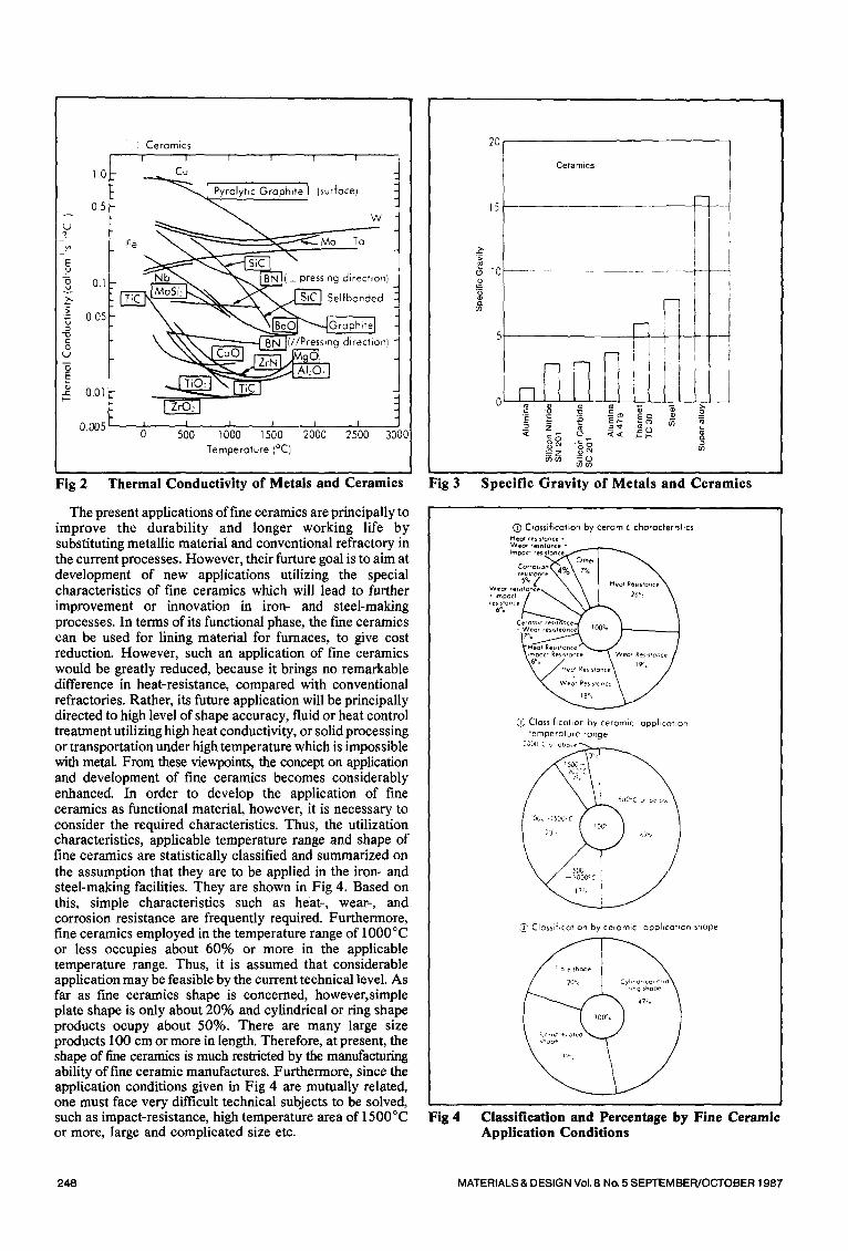
Fig 2 Thermal Conductivity of Metals and Ceramics Fig 3
The present applications of fine ceramics are principally to improve the durability and longer working life by substituting metallic material and conventional refractory in the current processes. However, their furture goal is to aim at development of new applications utilizing the special characteristics of fine ceramics which will lead to further improvement or innovation in iron- and steel-making processes. In terms of its functional phase, the fine ceramics can be used for lining material for furnaces, to give cost reduction. However, such an application of fine ceramics would be greatly reduced, because it brings no remarkable difference in heat-resistance, compared with conventional refractories. Rather, its future application will be principally directed to high level of shape accuracy, fluid or heat control treatment utilizing high heat conductivity, or solid processing or transportation under high temperature which is impossible with metal. From these viewpoints, the concept on application and development of fine ceramics becomes considerably enhanced. In order to develop the application of fine ceramics as functional material, however, it is necessary to consider the required characteristics. Thus, the utilization characteristics, applicable temperature range and shape of fine ceramics are statistically classified and summarized on the assumption that they are to be applied in the iron- and steel-making facilities. They are shown in Fig 4. Based on this, simple characteristics such as heat-, wear-, and corrosion resistance are frequently required. Furthermore, fine ceramics employed in the temperature range of 1000°C or less occupies about 60% or more in the applicable temperature range. Thus, it is assumed that considerable application may be feasible by the current technical level. As far as fine ceramics shape is concerned, however, simple plate shape is only about 20% and cylindrical or ring shape products ocupy about 50%. There are many large size products 100 cm or more in length. Therefore, at present, the shape of fine ceramics is much restricted by the manufacturing ability of fine ceramic manufactures. Furthermore, since the application conditions given in Fig 4 are mutually related, one must face very difficult technical subjects to be solved, such as impact-resistance, high temperature area of 1500°C or more, large and complicated size etc.
Fig 4
20
15
> ,
o
Ce ram ics
Specific Gravity of Metals and Ceramics
(~) Classification by ceramic characteristics Heor , e s , sm~ce * W*n r r~J~ t~n r~ °
Ciassificohon by ceramic apphcatton temperature range.
Classiflcahon by ceramic apphcation shape
47=¢
Classification and Percentage by Fine Ceramic Application Conditions
248 MATERIALS & DESIGN Vol. 8 No. 5 SEPTEMBEPJOCTOBER 198,7

Fine ceramics began to be used for partial application of substitutes for metal and this has gradually expanded based on the experience and accumulated results. Advancement of fine ceramics to the new field of iron- and steel-making processes may not be brought about before conventional design philosophy based principally on metallic material is changed, ceramic manufacturing technique and ability improved and especially, a stable supply of large size ceramic products are constantly secured in steel industry.
Table I shows the characteristics and application examples in the future of fine ceramics in iron- and steel-making facilities. Some of them have already been put into practical use.
Existing fine ceramic applications A study on application of fine ceramics to steel making
industry has just started. The fine ceramics, in reality, has not been as much utilized as expected. Examples up to now are shown on Table II. This includes application of materials, such as SiC, Si3N4, Zr02 and A1203, which are not so-called fine ceramics, but practically used as substitute for some conventional refractories or as the main material, paying attention to their characteristics and the material.
Table III shows the application examples of fine ceramics in iron- and steel-making facilities that were presented at the meetings of the Japan Iron and Steel Association for the past five years, arranged for each process field and yearly.
The present applications of fine ceramics are limited to a very narrow field and small in number, due to their characteristics and performance. However, the number presented at the Japan Iron and Steel Association has gradually increaed year by year, and the ranges of fine ceramic material, shape, and sections to be applied have all been expanded and diversified. Among them, some ap- plications are practically utilized after being long-term tested in the actual furnace. The application of fine ceramics presented in this paper is, however, just the tip of the iceberg and, although the data here are insufficient to foresee the general tendency, the concept of fine ceramic application to iron- and steel-making industry is broadly indicated.
According to this, the most advanced application of fine ceramics is to the rolling process field, such as open radiant
Table I Fine Ceramic Characteristics and Application in Iron- and Steel- making Facilities
Charac- teristics
of Application points fine
ceramics High heat ~kOLming for various furnaces resistance j:~;Mohen metal injection nozzle
<" High temperature heat exchanger ~Skid button i@Radlant tube ?~Protect tube for continuous tempera- I ture measurement i~] Burner parts
High ,.~High temperature fan blower strength (~Var ous rolling roll
i,~,Roll bearing j - , *SVar~ous valves i ~D*es i
High wear {£OFine particle transportohon pJpe resistance ~Slurry transportation piping and pump
ik~,Material hoaper i(i)Matenal processing sieve @Chute and liners L~ Grinding wheeJ
ODust catching filter @Molten metal inclusion removi%l fiher
Others
1130 sensor [~Cutting tools and cutter @Absortion mterial @Electrical insulation material ~Gas separation material
Remarks
O O O
O
O
O
Marked ~ i n the remarks means o partial or overall practical use.
tube, skid button, hearth roll, etc. The size and content aspect of the tests as well as the long-term serviceability of large size products are put into practical use. In the iron- and steel- making processes, tests have been conducted on comparatively less risky, replacable parts because of the size of risk and severe application conditions. However, in the steel-making processes, feasible study has been proceeding in a continuous casting field.
Table II Examples of Fine Ceramics Application in Iron- and Steel-making Industry
Application point Kind of Ceramics
~Lining on basic section of ascension pipe l Cord,er,te Coke oven j kLOLining on ascension pipe j Fused silica
k~Lining material for door I Fused s~!~ca
Material treqt- OWear-resistance lining for material hopper t r ment facility j LAFumma porcelain]
Iron making
Steel- making
Rolling
Common
I kb~Lining on the lower shaft E Sihcon carbide - s*licon n,tr!de OVenturi scrubber lining Silicon carbide - s~hcon n,tnde
Blast furnace (])Wear resistance lining for tuyere ends Zirconio - alumina k..~Heat resistance lining for the inside of tuyere , Silicon carbide
Hot stove O Ceramic burner Cord~er,te
(])Parts forCC IAlurnma, BN and S,C]
Q Reheating furnace skid button Reheating furnace radiant tube
(])Various hearth roll
(~) Heat exchanger
OProtect tube for continuous temperature measurement
(])Various lining for heat insulation (])O: sensor
[WC coating, etc. I
[Cordierite~ SiC, etcj
[Silicon carbde - silicon n,mdeJ
Ceramic fiber
Materials inJ ]are so-called fine ceramics and the others, conventional refractory structural cerampcs
MATERIALS & DESIGN Vol. 8 No. 5 SEPTEMBER/OCTOBER 1 g87 249

Table III Fine Ceramic Application Condition Presented in the Meetings of the Japan Iron and Steel Association
1980
Oct. Proces~-...~ (I 00)
Ironmokin~ 0
Steelmaking 2(0) Rolling 0 Others 0
Yearly total 2(0)
1981 1983 1984
Apr. A r. Oct. Apr. Oct. (101) (I~51 (108) (107) (]06) o o o o
1(0) 1(0) 0
1 9 8 2
Oct. A r. Oct. (I02) (I~3) (I04) 0 i 0 0 0 0 0 0 0 1(0) 0 0 0
1(0)
1(1) 0
i(o) 0 1(0) 2(0) , 2 (0)
1(I) 0 0 0 0 2(2) 3(0) 7(0)
Figures in parenthesis involve surface coating such as flame soray, application, etc.
The following introduces some application examples centering on the descriptions issued at the meeting of the Japan Iron and Steel Association.
Ceramic valve for controlling hot blast at blast furnace tuyere
It has been said that individual control of the blast volume at every blast furnace tuyere could make a good circumferential balance and give significant improvement in stable operation of the blast furnace. However, since the control apparatus has to be subjected to high temperature and pressure, it could not be realized due to problems in material and structure. In March 1984, a practical test of SiC ceramic valve was conducted at Nippon Kokan, Ogishima No 2 blast furnace. During the test period of about three months, operation conditions were excellent and no problematical abnormalities found in the ceramics after the testing, At present, the long- term test is still continuing. Fig 5 shows installation locations
Material Fine Ceramic SiC Type Butterfly valve Driving Electric
Temperature Nor 1100°C Max. 1 300°C
Condition Pressure 3.5--4kg/cm: Moisture Nor. 30 g/Nm s
Max. 40 g/Nm 3 • Control 1 20--200 NmJ/min
range Normal 170 Nm'Vmin
Table IV Specifications and Operation Conditions of Hot Blast Control Valve ~4~
[ Hot blast 1 Jc,ontrol valve I
Hot blast main
Recorder
I j ~ IPressure
Fig 5 Sehematle Figure of Hot Blast Control Ceramic Valve
Process 1985 classifi-
cation t o t a l
A r. (1 ~9) Total
1,1 i 2(1 ) O' 6(I) 0 611) I(01 2(11 2(I) 16141
of the ceramic valves, Table IV the valve specifications and operation conditions, and Fig 6 the test results of the valve.
Nozzle ceramics for horizontal continuous casting 15-7) The continuous caster widespread at present has a mold in the vertical direction and slabs are drawn downward from the top. In recent years, continuous casters of the horizontal type, which require inexpensive construction and main- tenance cost because of lower machine height and com- paratively easy equipment construction, have been under development. Bloom continuous casters with comparatively small cross-sectional area have been attempted for the practical use of under tests in Nippon Kokan, Sumitomo Metal Industries, Kobe Steel, etc. An example of them is shown in Fig 7. In this case, the mould is positioned in the horizontal direction and blooms are drawn horizontally. In the course of this, the joint refractory or break ring between
00
80
60~
40
2O)-
I
0 i 0
CLOSE
i ~ ~ 1 0 0
60 "~
°'°'°" ,! i • V/Vo I -~ _~P/z~ P,, -~20
I 1 I I 20 40 60 80 100
Valve opening (%) OPEN
:g
O
"5
B
Fig 6 Relation of Valve Opening Flow Rate and Pressure Drop
the tun-dish and mould plays an important role in order to draw blooms smoothly. As refractory material for these parts, fine ceramics such as BN, Si3N4, etc. are employed. The required characteristics of joint refractory are i) thermal shock resistance, ii) high lubrication, and iii) accurate machinability. Fig 8 shows an example of joint construction between the tun-dish and mould and Table V, an example of test nozzle material and casting conditions. In this report, Si3N4 with low heat transfer is much better than BN in operation ability and bloom characteristics. Casting of bloom 60m or more in length and durability of 4 hrs or more casting hour are achieved as operation results is Nippon Kokan.(5)
250 MATERIALS & DESIGN Vol. 8 No. 5 SEPTEMBER/OCTOBER 1987

10 ton ladle
©
Synchronized cutter
t Dummy bar I II " '
0 -0 0 0 --O/Q,..-%~,...-O 0 (3
Cooling bed
T Tundish
raw,ng dev,ce o,or ,oray ",
M V I I - - - ,o , o ,
Fig 7 Schematic Figure of Testing Facilities ~6>
Front Nozzle \
i I
i I
Feed Tube
Mould
Seating Ring / zk Ring
Fig 8 Construction of Connection Between Tun-dish and Mould ~5>
Si,N~-AIN-BN i BN ! Material Refractor'/] Production nozzle method
Thermal conduct iv i ty
Steel grade
Reaction sinter I Hot Dress
5 -10kca l /m 'h r . °C 20 '
Casting rate Wi thd rawa l c y c l e
SUS316(18Cr-12Ni-2Mo)
Billet size 185 rnm dia. ' 0,8 m/min. 40 c/min
Table V Nozzle Refractory material and Casting Conditions ~7)
Ceramie filter for removing inclusion~ 9,1°) In reduction of DI (draw and ironed) cans for tin plating, cold rolling sheet for deep drawing, steel cord for tire, etc., even inclusions as fine as about 10pro will result in the causes of surface flaws, cracks and discontinuity in manufacturing. Thus, because flotation removal is almost impossible, a new inclusion removal method using ceramic filters has been studied. This method using ceramic filters has been studied. This method has been adopted in the aluminium industry since early days. Recently, movement for adoption of fine ceramics to high temperature liquid has become active. As to employment of Ni alloy, application effects of three dimensional pattern and lattice pattern filters are reported in USA. Fig 9 shows the appearance of such filters. The filter
Three dimensional Net type filter
Direct-through Mul- tiple hole type filter
Fig 9 Shapes of Ceramics Filters
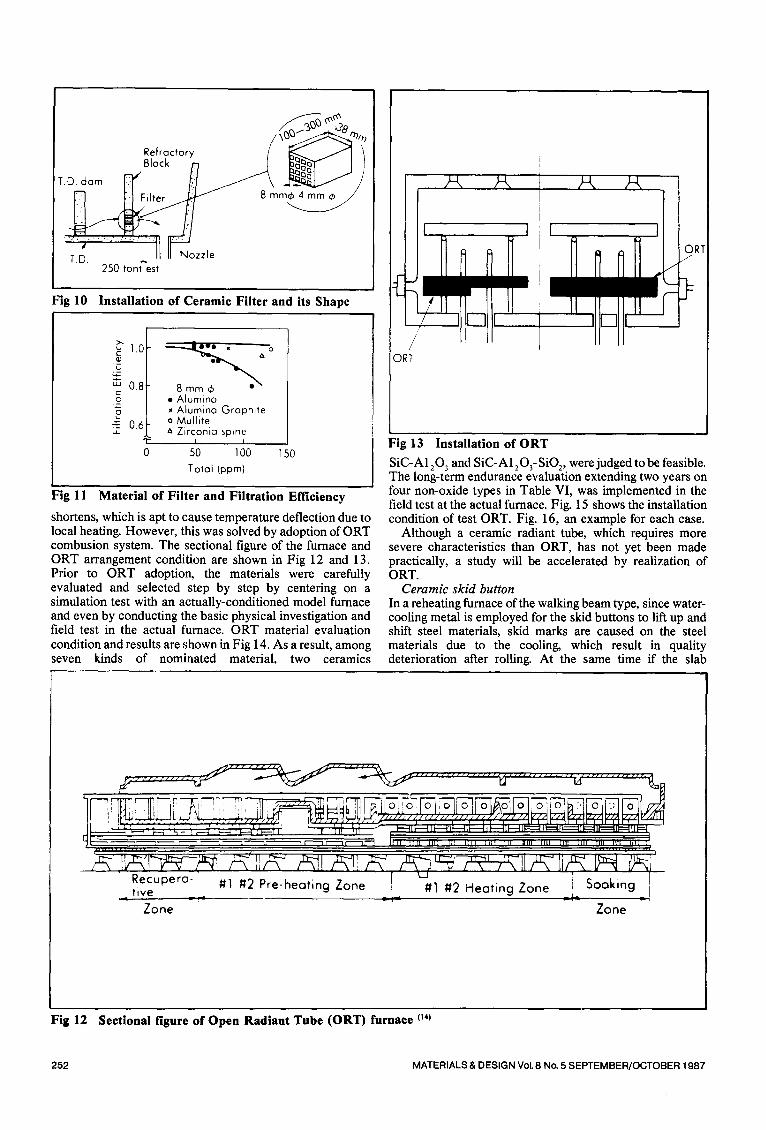
material includes alumina and zironcia types and is composed of those that endure at the temperature level of molten steel. The filter is generally installed in the tun-dish because such location is as near the solidification positin as possible and does not interfere with the operation. Fig 10 shows an example of it. This is the case of Nippon Kokan, Ogishima Works, and casting of 250 tons charge is completed by utilizing the grid type filter shown. Four kinds of materials, such alumina, alumina-graphite, mullite, and zirconia spinel, are used for it. Although the filtering rate of inclusions is said to be small in this test, as shown in Fig 1 l , some cases are judged to be effective in laboratories. Furthermore, as filtration increases, clogging problem may arise. For the practical use, therefore, many technical subjects remain as to not only material and shape of the filter but also the application method (such as replacement type, etc.)
Open radiant tube (ORT) (14-16) In order to cope with diversity and high grade requirement in the needs of plate products, the plate mill in NSC Nagoya Works modified the existing reheating furnace into that of a R T combusion type. This furnace is intended to handle slab heating in the wide temperature area ranging from less than 1,000°C to more than 1,200°C, with excellent uniformity in the temperature, high efficiency, and low energy requirement. The furnace has been operating smoothly since September, 1983 and has been demonstrating its effects adequately.
In the conventional reheating furnace, flame length
MATERIALS & DESIGN Vok 8 No. 5 SEPTEMBER/OCTOBER 1987 251
Refractory / ~ ~ Block J)
T.D. ctom ~ f::/ ~ ~ /
. ' : ) . ' . ' . : . : : . . . ,
250 tont est
Fig 10 Installation of Ceramic Filter and its Shape
ORT
1.0 ~J G
0.8 g 5 .=- 0.6
0 150
O w l x ~ O
• Alumina Alumina Graphite
o Mullite " Zirconia spinel
I I
50 100 Total (ppm)
Fig 11 Material of Filter and Filtration Efficiency
shortens, which is apt to cause temperature deflection due to local heating. However, this was solved by adoption of a R T combusion system. The sectional figure of the furnace and a R T arrangement condition are shown in Fig 12 and 13. Prior to a R T adoption, the materials were carefully evaluated and selected step by step by centering on a simulation test with an actually-conditioned model furnace and even by conducting the basic physical investigation and field test in the actual furnace. ORT material evaluation condition and results are shown in Fig 14. As a result, among seven kinds of nominated material, two ceramics
Fig 13 Installation of ORT
SiC-A1203 and SiC-A1203-SIO2, w e r e judged to be feasible. The long-term endurance evaluation extending two years on four non-oxide types in Table VI, was implemented in the field test at the actual furnace. Fig. 15 shows the installation condition of test ORT. Fig. 16, an example for each case.
Although a ceramic radiant tube, which requires more severe characteristics than ORT, has not yet been made practically, a study will be accelerated by realization of ORT.
Ceramic skid button In a reheating furnace of the walking beam type, since water- cooling metal is employed for the skid buttons to lift up and shift steel materials, skid marks are caused on the steel materials due to the cooling, which result in quality deterioration after rolling. At the same time if the slab
Zone Zone
Fig 12 Sectional figure of Open Radiant Tube (ORT) furnace o4)
252 MATERIALS & DESIGN Vol. 8 No. 5 SEPTEMBER/OCTOBER 1987

om reh~,.t' 0 ~ ' NO Good ~.® I~,~,,o ing f u r n a c e , < ~ m I usePractical ~ Good ,~ = ,°:z
TLong-term i c ° n d u r a n c e I
i Oxiclat i . . . . . ist . . . . i - - ~ © ,~ I L .
S c a l e r e s i s t a n c e ~ , ~
s; q -,' c - b - o - H e a t r e s i s t a n c e
, / j f
aRT requi, ed / " c i l a r a c t e r r s u c s ~
ame of test sample
j ~ °~ A 1 2 0 S iC SiC S i C SiC ~ ~1' ~
~ I AI 0 ! - - I ~) : ~ ZrO SiO~ S i _ N ~ _ ^ A =0 I
p _ Z . . . . . . . . . . ?___q
C e r a m i c t u b e
Table VI Chemical Composition of ORT Fine Ceramics
T Chemical composmons
Samples bSC - - ~
s , C - A i O , 5 3 - ,~ 30 j ~ 2 0 0 3 Sc ~ , 0 S,O 900 - 70 " 0 8 02
S,C.S, N . 73.3 223 29 0 3 0 S
S,C-S,O i 95.2 [ -- 3 ' 02 02
Fig 14 Evaluation of Materials of ORT
discharging temperature is increased to prevent this phenomena, it becomes disadvantageous from the standpoint of energy-saving. As measures against this, the skid using ceramic buttons has been under development.
The required characteristics for skid button ceramics are the shock resistance (physical and thermal), wear resistance, scale resistance, oxidation resistance, etc. The materials
Fig 16
Testing period: 24 months Material: SiC-AI~O~-SiO~
, - d . ~ Installahon place: soaking zone
ORT Appearance After Testing in Plate Heating Furnace
+ . . . .
k ....
R e c u D e r a r , v e z o n e
' ~ O R T i n s t a l l a t i o n R e c u p e r a t i v e z o n e s e c t i o n S o _
! I \ / ~ea,,,g'. \, ~: S,CAIO zo,~e ~ ~ ~: SiC AI O -S,O
; 2 ,~ S~C-SiO
I
I
I I So.,~a [ ] Cro~ks 1 Broken
Condmon after ~, 24 months
_Q
- cn kJ ao
SiC-A I :O~ l l .~ ,, . +
5 * =o SiC-Si~N~ ~ l l
split ~ t_ -A : C ) ~ - S i O - 1 ~ 11, l
Half split is the condition after 18 months
Fig 15 ORT Arrangement and Evaluation Results in Plate Reheating Furnace
MATERIALS & DESIGN Vol. 8 No. 5 SEPTEMBER/OCTOBER 1987 253

Table VII Example of Materials and Characteristics of Ceramics for Skid Button Use
Items
Ratio of Density (%)
Modulus of Rupture (kg/mm :)
Ceramics
R.T.
Si~N~
96-98
60~70
SiC
94.5~96.4
42-47 at 1200°C 30--35 38-43
Thermal Expansion x 10 7/°C 33"-35 42-45 at 100°C 16-17 38-39
at 400°C 13 -14 32-33 at 800°C 12-13 26"-27
Thermal Conductivity (kcal/m.h.°C)
Fine Ceramics
5mm~ I " I ' ~ ) /
Insulation F ---1 Ceramics
Saddle x : Thermo Couple
11, T ~ , , I
r ~ , Ceramic Button Q
"vl x-..- .---~'v b-"tf--r-~v I ~ y ~\ / ~.,,t
8 ~ , v I ~, Metallic Button @
Metall ic Button Q : I i / I
" x Cerom,c Button'k~ ! I I , , i I I 5 4 3 2
Time (houri
Fig 17 Schematic Figure of Ceramic Button and its Internal Temperature Fluctuation
studied up to now are principally SiC and SisN 4. The main reason for this is that they possess high strength under elevated temperatures of 1,000°C or more. Table VII shows the material and characteristics of ceramics used in the actual furnace test at the reheating furnace of walking beam type in Nippon Kokan, Keihin Works.
Moreover, in a practical use, structural design is more important than the ceramic itself. Various studies have been made on button holding, insulation and impact reduction between the saddle and button, etc. Fig 17 shows the
construction of ceramic buttons employed in the above- mentioned furnace, with insulation ceramic underneath it. In this case, it was evident, based on the results of temperature measurement, that the temperature at the position 5 cm fromt he button surface was 140°C higher than that of the metal upon material discharging, and it is judged that the ceramic buttons are effective as the measures against skid marks. In Nippon Steel, the shock-resistance is considered to be especially important as the required characteristics of the skid, and thus the simulator or enabling repetitive impact tests in the hot conditions was manufactured as shown in Fig 18.
In the experiment, repetitive shocks were given 40,000 to 520,000 times (equivalent to one month to one year of the actual furnace operation period) with the maximum tem- perature of 1,400°C. As a result, it was evident that SiC- A1203 ceramics were superior under the button surface temperature of more than 1,100°C and that the durability was significantly improved by provision of shock reduction mechanism. Based on this, the ceramic skid provided with a disk spring under the button to reduce impact force, as shown in Fig 19, has been used in the actual furnace. Fig 20
D------C
7/- / /
Equipment specifications Weight of hammer: About 13 kg Diameter of hammer: ,~95 Dropping distance: About 23 cm Dropping cycle: 100 cycle/min. Temperature: !400 °C maximum
Fig 18 Ceramic Button Simulator
Q (~) Ceramic button O Retainer O Intermediate plate
Disk spring Q Bottom adjustment plate
Fig 19 Schematic Figure of Skid Button
254 MATERIALS & DESIGN Vol. 8 No. 5 SEPTEMBER/OCTOBER 1987

exemplifies the condition of the ceramic skid used in the soaking zone of a plate reheating furnace for about 7 months.
Although some ceramic skids endure more than two years as record, fine ceramics are still insufficient to endure at a high temperature range and further study is required to be made.
Ceramic hearth roll With the high grade requirement in the quality level of continous galvanizing line, pressed flaws caused by foreign matter adhering to the rolls of a reheating furnace have become problematic. For measures against this problem application of ceramic sleeve, ceramic lavaflame, etc. are considered. Table VIII shows the evaluation of each material used for No 2 continuous galvanizing line non-oxidation zone (NOF: < 1,300°C) and reheating zone (HF: _ < 1,000°C) in Sumitomo Metal Industries, Wakayama Works. Based on this molten silica has been employed as the optimum material. Because SiC has superior thermal resistance and has, in NOF, build-up prevention effect although slight surface oxidation is found, it is scheduled to be adopted in future. Furthermore, it was evident that ceramic lavaflam and A1203 sleeve had a short service life due to cracks, etc and were unaccepted for the practical u s e .
Fig 21 shows the construction of hearth roll of sleeve type employed in a continous galvanized line, and Table IX, its main specifications. The feature of the roll is that the sleeve and arbor are of clearance fit construction to protect fragile material such as ceramics etc from shock caused upon driving and stoppage, and that rotation transmission such as needle thread and strip forward is made by utilizing friction force between the sleeve bore and arbor. In addition, for material (SIC, Si3N 4, etc.) susceptible to thermal shock, insulation net is inserted into the space between the sleeve and arbor as shown in Type 2 (Fig 21).
Table VIII
Fig 20 Appearance of Ceramic Button After Reheating Furnace Test (12~
Water
L Sleeve Type Hearth Roll .TYPE 1'
SteeJ Net Arbor,, ~ - ~
~ 'Sleeve
Thermal Shock Res,stant Roll TYPE 2
Fig 21 Schematic Figure of Ceramic Sleeve Roll
Actual Furnace Evaluation Data of Each Sleeve Materials
Metalizing Carbon Fused
Silica Fine Ceramic
A I : O ~ ZrO~ AltO, ShN~ SiC
Flexural Strength !kg/mm:) -- 4.5 2.0 37 50 58 Thermal Shock Resistance ~C -- 300 up :1000 200 480 500 Thermal Expansion Coeffic,ent 9.0x10 6 4.6x10 6 .0.4x10 6 7.7x10 6 3.0x10 ~ 45x10 ~ Bulk Density - 1 .77 1.95 3.62 316 32
Heat p roo f °C 1200 " 1200 ] 0 0 0 "-]200 1200up
Resistance to N o r D D ~ A--
Pick-up HF B B A A -- A A~-
Life N o r 0 5 0.5 -- 6 -- -- 6
Instantly (~n monthsl HF I 0 20 1 week over 6 Broken I week over 6
Material Cost (yen/kgi 10,000 6,000 10,000 30,000 60,000
NOTE: Resistance to Pick-up: Grading; better A B, C, D worse.
Table IX Specifications of Testpiece Rolls
TYPE 1 TYPE 2
The examples mentioned above are only a part of the
Sleeve Length Sleeve Diameter Arbor Length Arbor Diameter Arbor Material Cooling Method
1,680 120/74 2,955 70/18
1,680 120/100 2,955 92/18
SUS 310S Water
SUS 310S Water
investigation but are the ones that gained good results. Furthermore, these examples have common features that they have investigated not only fine ceramic materials but also design and operations. From this point of view, as well, it is sure that application of fine ceramics has been steadily progressing.
Technical aspects to be overcome and prospects in the future The application scope in the steel industry of fine ceramics seems to be very wide. However, when such applications are
MATERIALS & DESIGN Vol. 8 No. 5 SEPTEMBER/OCTOBER 1987 255

actually studied, there are many problems involved. The material technology has been developed with a notion centering on metal, and experience richly accumulated in each field of production, design and operation techniques. Consequently, there is a common recognition that metal is "familiar to be produced" and"familiar to be used", hence it gives us a sense of assurance.
On the contrary, fine ceramics are a new material and"not familiar to be produced and applied". Therefore, there is always a sense of uncertainty in their use. In order to overcome this, there is no other way but to solve technical aspects, elements of uncertainty, one by one carefully and tenaciously.
Based on those viewpoints, the following items are considered to be especially important as technical subjects to be studied:-
i evaluation technique of fine ceramics in applications ii structural design concept suitable for fine ceramics iii manufacturing technique that economically realizes
the desirable characteristics iv improvement in the reliability of fine ceramic
products (mutually related with design method) v technique ofjointing with and fitting into metal vi application, repair, and fabrication techniques of fine
ceramics for equipment The technical subjects described above are only predictions,
so if definite applications of fine ceramics are developed in the future, its damaging mechanism will be disclosed and location of problem will become more clear. Consequently, technical development of fine ceramics will be accelerated.
For this, the accumulation of minor trial results described previously is very important.
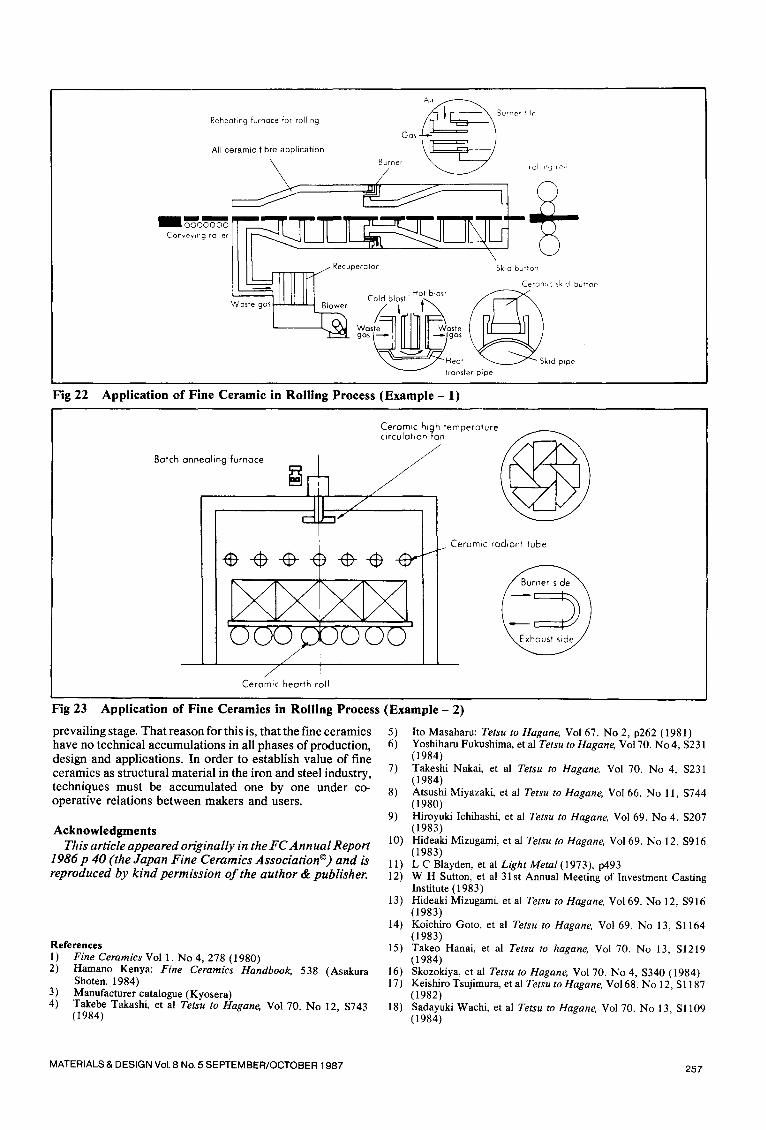
In the future, where and how fine ceramics are utilized in: the iron- and steel-making industry will be clarified as the above mentioned technical subjects are solved. Application conditions of fine ceramics in future will be predicted, putting emphasis on higher needs from users (3) viewpoint. It is our dream to develop a perfect and compact continuous iron- and steel-making process of ultra-energy saving type, using fine ceramics in lining, runners, tuyeres, sensors, etc., which produces highly purified steel very efficiently. This may be, however, criticized as too unrealistic today. Therefore, the concept of fine ceramics application to each part of the rolling process which has the highest demand for fine ceramics as present was summarized and its results is shown in Table X. Then, the states of totally utilizing such applications in continuous reheating furnace and batch annealing furnace are given in Fig 22 and 23.
Although the predicted configurations expressed in those figures are not much different from those of the present equipment, this may be due to my poor imagination. The equipment itself must be compact with largely improved energy saving, operationability and service life.
Conclusion Although there are too excessive expectations on fine ceramics, saying that "the second stone age comes," it is widely recognized the fine ceramics are worth evaluating from the viewpoint of their characteristcs. At present, however, only partial applications are seen, far beyond the
Table X Concepts of Fine Ceramic Application in Rolling Process
Place Current Problems Needs Required characteristics
Ceramic • Metallic heat exchange • Waste gas temperature rise • High heat resistance recuperator waste gas upper limit: by hot charge: 1100°C • High thermal conductivity
850°C • High efficiency high • Low permeability temperature recuperator • Spalling resistance
Burner • Insufficient combustion • Temperature rise in • Heat resistance efficiency improvement combustion air • Spalling resistance due to inadequate heat (>700°C) resistance of burner parts
Ceramic skid • Occurrence of skid mark • Reduction in skid mark • Mechanical impact (increase in heat loss) (Reduction in heat loss) resistance
• Spalling resistance
• Current endurance • Hot mechanical strength temperature 600°C
High temperature fan (blower)
Radiant tube
Ceramic roll for transportation
Ceramic roll for rolling
• Present: 1100°C • Improvement in combustion
temperature • Improvement in combustion
efficiency
• Large heat loss • High temperature hot slab/
bloom measure due to hot charge (800 - 1100°C)
large wearing damage Measures against scale adhesion Heat loss (by cooling water, etc.)
• Increase in processing temperature (>800°C)
• Circulation of high temperature gas
• Use of high temperature preheating air
• Ceramic radiant tube: 1300°C
• Heat loss measures • Measures against hot charge
• High endurance roll [Wear resistance, spalling resistance, and toughness[
• Heat resistance • Spalling resistance • Low permeability
• Small thermal conductivity • Spalling resistance • Toughness
• Wear resistance characteristics
• High strength characteristics
Ceramic hearth • Large heat loss • Low heat loss • Low thermal conductivity roll • Insufficient heat resistance • High strength
256 MATERIALS & DESIGN Vol. 8 No. 5 SEPTEMBER/OCTOBER 1987
~ B u r n e le rh Reheating furnace for rolling Gas
All ceramic fibre application
Burner ~ rail,ha r:,:,
_ ,
I' "t II II III cold blas,-H°L bl°~' v~a'~ega't--"""- ~ al . . . . ~ ~ I \ / I / I \
~ Heat ~ Sktd p~pe transfer plpe
Fig 22 Application of Fine Ceramic in Rolling Process (Example - 1)
Batch annealing furnace
Ceramic hiqh temperature circulation :fan
_ i Ceramic hearth roll
/ Ceramic radiant tube
Fig 23
prevailing stage. That reason for this is, that the fine ceramics have no technical accumulations in all phases of production, design and applications. In order to establish value of fine ceramics as structural material in the iron and steel industry, techniques must be accumulated one by one under co- operative relations between makers and users.
Application of Fine Ceramics in Rolling Process (Example - 2)
Acknowledgments This article appeared originally in the FC Annual Report
1986p 40 (the Japan Fine Ceramics Association ©) and is reproduced by kind permission of the author & publisher.
References 1 ) Fine Ceramics Vol 1. No 4, 278 (1980) 2) Hamano Kenya: Fine Ceramics Handbook, 538 (Asakura
Shoten. 1984) 3) Manufacturer catalogue (Kyosera) 4) Takebe Takashi, et al Tetsu to Hagane, Vol 70. No 12, $743
(1984)
5) Ito Masaharu: Tetsu to Hagane, Vol 67. No 2, p262 (1981) 6) Yoshiharu Fukushima, etal Tetsu toHagane, Vo170. No4, $231
(1984) 7) Takeshi Nakai, et al Tetsu to Hagane. Vol 70. No 4, $231
(1984) 8) Atsushi Miyazaki, et al Tetsu to Hagane, Vol 66. No 11, $744
(1980) 9) Hiroyuki Ichihashi, et al Tetsu to Hagane, Vol 69. No 4, $207
(1983) 10) Hideaki Mizugami, et al Tetsu to Hagane, Vo169. No 12, $916
(1983) 11) L C Blayden, et al LightMetal(1973), p493 12) W H Sutton, et al 31 st Annual Meeting of Investment Casting
Institute (1983) 13) Hideaki Mizugami, et al Tetsu to Hagane. Vo169. No 12, $916
(1983) 14) Koichiro Goto, et al Tetsu to Hagane, Vol 69. No 13, Sl164
(1983) 15) Takeo Hanai, et al Tetsu to hagane, Vol 70. No 13, S1219
(1984) 16) Skozokiya, et al Tetsu to Hagane, Vol 70. No4, $340 (1984) 17) Keishiro Tsujimura, et al Tetsu to Hagane, Vo168. No 12, S1187
(1982) 18) Sadayuki Wachi, et al Tetsu to Hagane, Vol 70. No 13, Sl109
(1984)
MATERIALS & DESIGN Vol. 8 No. 5 SEPTEMBER/OCTOBER 1987 257