application of evolutionary computation in automotive...
TRANSCRIPT

Shock and Vibration 13 (2006) 85–102 85IOS Press
Application of evolutionary computation inautomotive powertrain mount tuning
Anab Akanda∗ and Chandu AdullaDaimlerChrysler Corporation Detroit, MI, USA
Received 3 December 2004
Revised 19 September 2005
Abstract. Engine mount tuning is a multi-disciplinary exercise since it affects Idle-shake, Road-shake and power-train noiseresponse. Engine inertia is often used as a tuned absorber for controlling suspension resonance related road-shake issues. Last butnot least, vehicle ride and handling may also be affected by mount tuning. In this work, Torque-Roll-Axis (TRA) decoupling ofthe rigid powertrain was used as a starting point for mount tuning. Nodal point of flexible powertrain bending was used to definethe envelop for transmission mount locations. The frequency corresponding to the decoupled roll mode of the rigid powertrainwas then adjusted for idle-shake and road-shake response management.
A TRA decoupling procedure, cast as a multi-objective optimization problem, was applied to a body-on-frame sport-utilityvehicle powertrain system. In addition to a standard gradient based optimization algorithm, available in commercial finite elementsoftware, an evolutionary computation paradigm known as Evolutionary Strategies (ES) was used to solve the optimizationproblem. The primary advantages of evolutionary computation over gradient based algorithms are as follows: i) They are lesslikely to get trapped in local minima and less dependent on initial values of the design parameters and therefore able to handlemulti-modal optimization problems unlike gradient based algorithms, ii) They produce a population of viable solutions, unlikegradient based algorithms which yields a single solution. The second advantage is very attractive in a production environmentsince packaging and other multi-disciplinary constraints often require multiple quality solutions for the same problem. Theprocess outlined in this work was verified by exercising a full-vehicle finite element model. The process produced a set ofproduction feasible powertrain mount parameters for acceptable idle and road shake performance.
1. Introduction
A four-wheel-drive (4WD) automotive powertrain usually consists of three major components: i) Engine, ii)Transmission and iii) Transfer case. Powertrain mount design affects multiple performance attributes of a modernautomobile. Starting from vehicle ride and handling quality, low-frequency vibration, higher frequency noise tocrashworthiness are all affected in some fashion by the powertrain mounting strategy. The focus of this work,however, is limited to the aspects of mounting strategy that affect low frequency vibration response due to pulsatingengine idle torque and road profile induced input. Engine mounting strategies discussed here are particularly relevantto rear-wheel (or 4 wheel-drive) drive vehicles with “north-south” powertrain orientation.
As far as noise and vibration is concerned, the primary function of powertrain mounts is to isolate the vehiclebody structure from any powertrain induced vibration source. Under wide/part-open-throttle conditions, modes ofthe flexible powertrain play a major roll in powertrain induced vehicle interior acoustic response. In this situation,isolation provided by the mounts is critical [1]. Locating the transmission mounts near or at the nodal point ofthe fundamental bending mode of the powertrain can significantly reduce the amount of forces transmitted to thebody. Therefore, in any engine mount tuning exercise, location of the transmission mount is subjected to the aboveconstraint.
∗Corresponding author. E-mail: [email protected].
ISSN 1070-9622/06/$17.00 © 2006 – IOS Press and the authors. All rights reserved

86 A. Akanda and C. Adulla / Application of evolutionary computation in automotive powertrain mount tuning
Under engine idle conditions, the pulsating torque generated by a multi-cylinder engine is one of the major sourcesof vibration. The torque frequency spectrum exhibits concentration of energy at various frequencies dictated bythe engine idle rpm, number of cylinders and associated engine orders. For instance, a V6 engine would typicallyexhibit peaks in the frequency response related to some of the following orders: 1 st, 1.5, 2nd, 2.5 and 3rd. In shortof addressing the source of these orders caused by cylinder-to-cylinder gas pressure variation, unbalanced inertiaforces etc., one is left with only two major design enablers for achieving good idle vibration response of the vehicle:i) provide maximum vibration isolation by choosing low mount rubber stiffness and ii) decouple the rigid-bodymodes of the powertrain. The first strategy is a fundamental principle in vibration control, while the second one isbased on the following observation. In [2], Jeong et al., states: “If a system is completely decoupled in physicalmodes, excitation along one physical co-ordinate should excite only one mode . . . Even when two or three differentexcitations are simultaneously applied to the powertrain, projected excitations along the physical co-ordinates mayhave only a few non-trivial values.” In the same article, the authors provided analytical comparison of all existingdecoupling schemes namely: i) Focalization method, ii) Partial elastic axis decoupling method and iii) Torque-Roll-Axis (TRA) decoupling method. They have proposed a new axiom for the TRA decoupling and clearly demonstratedthat only the TRA mode decoupling scheme provides a complete decoupling of physical modes. They derived sixequations representing the conditions for a complete decoupling of the TRA mode. If these equations are satisfiedthen the response of the powertrain center-of-gravity (CG) due to oscillatory torque applied about the crank-shaftwill exhibit only one peak at the roll-mode about the Torque-Roll-Axis. Response of the CG in other co-ordinateswill be identically zero. They also derived analytical expressions for optimal parameters in the special case when themounting planes are fixed. Albeit, very useful and insightful, this assumption may be too restrictive in a productionenvironment. For a 4-mount system there are 36 design parameters corresponding to location, orientation angles andstiffness. This implies that one may adjust only up to six variables while holding the remaining parameters constant.In this work, instead of using the aforementioned six equations directly, the TRA decoupling procedure was cast asa multi-objective optimization problem. If the frequency response of the CG, defined in the TRA coordinate system,for all degrees-of-freedom except rotation about the torque-roll-axis, is minimized with respect to all 36 variablesthen the resulting system will automatically satisfy the six equations and produce a completely decoupled TRA mode.The optimization problem was first solved by a standard gradient-based method implemented in the commercialfinite element software MSC/NASTRAN [3]. While setting up the optimization problem in MSC/NASTRAN,several difficulties were encountered. First, it was not possible to define location and spring rate of the mountssimultaneously as a common set of design variables in a single optimization run. Secondly, the orientation angles(euler angles) of mount could not be directly defined as design variables. An indirect method had to be developedto accomplish this. Therefore, the locations, rates and orientation had to be optimized sequentially. While thisprocedure produced acceptable results, the authors felt that two main problems common to all gradient-based searchtechniques, i) Entrapment in local minima, ii) Dependence on a good starting point, could be avoided if a non-gradient based algorithm such as evolutionary computation was adapted. There are three evolutionary computationalgorithms that have been successfully employed in many difficult optimization problems in industry. A long listof references on application of evolutionary computation can be found in [4]. These three independently developedparadigms: i) Genetic Algorithm (GA), ii) Evolutionary Programming (EP) and iii) Evolutionary Strategies (ES),are based on the mechanics of natural selection and natural genetics. These methods have established a reputation ofbeing very robust search algorithms in recent years [5–9]. Genetic algorithm has been successfully applied to vehicledriveline vibration problems [10]. Here the authors compared the performance of GA with a standard simplex searchalgorithm. In [11], genetic algorithm was used to solve an engine mount optimization problem. In their work, theoptimization problem was limited to minimization of off-diagonal terms of the stiffness matrix. This is essentiallya partial elastic axis decoupling technique described in [2]. However, the authors did not compare the performanceof GA with other standard search algorithms. In the present work, the Evolutionary Strategies (ES) algorithm wasadapted to solve the TRA optimization problem. This particular paradigm was chosen over the other two for thefollowing reasons: i) The algorithm is very easy to implement, ii) Linear constraint handling is straight forward andiii) It performs particularly well on continuous function optimization problems [4,6,9].
The road-profile induced low frequency vibration (less than 20 Hz) felt at the steering wheel and seats by thepassengers is commonly referred to as Road-Shake. Under this loading conditions, in body-on-frame sport-utility-vehicles, typically there is a lot of interaction between powertrain and suspension modes. The global body modes

A. Akanda and C. Adulla / Application of evolutionary computation in automotive powertrain mount tuning 87
such as bending and torsion are usually well separated from the suspension and powertrain modes. A commonstrategy often adapted to attenuated the suspension/powertrain coupled vibration is to use the powertrain rigid bodymodes as a tuned-mass-absorber [12]. In particular, engineers attempt to place the bounce (vertical translation)mode frequency of the powertrain on top of the front suspension hop mode (vertical translation) frequency whilethe roll mode frequency of the powertrain is placed at or near the suspension tramp mode (out-of-phase verticaltranslation) frequency. If the powertrain rigid-body modes are reasonably decoupled then they can be effectivelyused as a tuned-mass-absorber for both hop and tramp mode of the suspension. This is even more effective whenthe suspension is not independent (solid axles).
In this work, the ideas introduced in [2] were extended and applied to a production vehicle program with a V6powertrain supported by a 4-mount system. The basic strategy adopted here was three fold: i) Decouple powertrainrigid-body modes by TRA decoupling procedure and obtain uncoupled roll mode for idle vibration quality, ii) Lowerthe roll-mode for increased vibration isolation, and finally, iii) Adjust the frequencies of the powertrain modes suchthat they can function as a tuned-mass-absorber to attenuate suspension-resonance related system response due torough road profile input. In addition, an envelop was defined around the nodal point of the powertrain flexible bendingmode, for transmission mount locations. Finally, the lower-limit of the mount isolators and corresponding orientationangles were fixed such that the static load-bearing and vehicle handling requirements are not compromised. Theperformance of the optimal mount parameters were evaluated in a full-vehicle production finite element modelsubjected to idle torque and road-shake load cases.
The remaining part of this paper is organized as follows: 1) Derivation of the TRA decoupling scheme, 2)Formulation of the optimization problem in MSC/NASTRAN followed by ES, 3) Finite element simulation ofIdle-Shake and Road-Shake, 4) Results and 5) Conclusions.
2. Equations of motion
The (6 × 6) equations of motion of a rigid-body powertrain CG in a reference co-ordinate system can be expressedin matrix form as follows:
[M ]�̈xg + [C]�̇xg + [K]�xg = �0 (1)
The mass matrix is given by⎡⎢⎢⎢⎢⎢⎢⎣
m 0 0 0 0 00 m 0 0 0 00 0 m 0 0 00 0 0 Ixx Ixy Ixz
0 0 0 Iyx Iyy Iyz
0 0 0 Izx Izy Izz
⎤⎥⎥⎥⎥⎥⎥⎦
(2)
where m is the mass of the powertrain and [I] is the corresponding inertia matrix. The diagonal isolator stiffnessmatrix of each mount in local co-ordinate system is transformed to the global reference co-ordinate system. Thenthe sub-matrices are assembled to form the global stiffness matrix [K]. Similarly, a proportional damping matrix,[c] can also be transformed and assembled to obtain the global damping matrix [C]. Derivation and definition of theelements of global symmetric [K] and [C] matrices are given in [13–15]. The eigen value problem associated withEq. (1) is expressed as
Ku = λMu (3)
Solving Eq. (3) yields six eigen values, λ and the corresponding modal matrix, U. Frequency response of the CG,xg(ω), can be computed by the modal superposition technique [16]. The Fourier transform of the impulse responsefunction hr(τ) is defined as
Hr(ω) =1
ωr2 − ω2 + 2jζrωrω
(4)

88 A. Akanda and C. Adulla / Application of evolutionary computation in automotive powertrain mount tuning
where ωr is the rth modal frequency, ω is the driving frequency, ζ r is the rth proportional modal damping ratio. Thetransfer function matrix for the system is given by
[H(ω)]ij =nmode∑r=1
UirUjrHr(ω) (5)
where Uij are the coefficients of the modal matrix. Finally, the response of the CG co-ordinates due to a harmonicinput can be expressed in terms of the modal coefficients as follows
Xi(ω) = [H(ω)] �F (ω) (6)
where �F (ω) is a harmonic load vector. The response magnitude of the i th degree-of-freedom can be written as
|Xi(ω)|2 =ndof∑l=1
ndof∑m=1
[H ]∗il [H ]jm F ∗l (ω)Fm(ω) (7)
3. TRA decoupling
As stated in [15], when an oscillatory torque is applied to a rigid body, supported by soft isolators, about an axisother than one the principal axes of inertia, it will rotate about an apparent axis that is neither a principal axis ofinertia, nor the axis of the oscillatory torque. This axis is referred to as the torque-roll-axis (TRA). Mathematicaldefinition of TRA is given in [2]. One can define a co-ordinate system in which the x-axis is parallel to the TRA. Inthe following, such a co-ordinate system will be denoted by ΓTRA. Let the inertial reference co-ordinate system forthe rigid powertrain be denoted by Γg . Note that the crank-shaft axis is assumed to be parallel to the x axis of Γg .The equations of motion given by Eq. (1) can also be expressed in the Γ TRA axis instead of the inertial co-ordinatesystem, Γg . Of course, now the [M ], [K] and [C] must be transformed and reassembled in the Γ TRA system. Theundamped equations of motion in Eq. (1) is redefined in ΓTRA axis as follows
[M ]�̈xTRA + [K]�xTRA = �0 (8)
corresponding eigen value problem is
KqTRA = λMqTRA (9)
A complete decoupling of the TRA mode from other physical modes is possible only when the TRA direction,qTRA = [0 0 0 1 0 0]T is one of the natural modes. Substituting this condition in Eq. (9) produces six equations [2]
n∑i=1
(kxziayi − kxyiazi) = 0,
n∑i=1
(kyziayi − kyyiazi) = 0,n∑
i=1
(kzziayi − kyziazi) = 0,
n∑i=1
(kyyia2zi
+ kzzia2yi− 2kyziayiazi = λIxx, (10)
n∑i=1
(kxziayiazi + kyziaxiazi − kzziaxiayi − kxyia2zi
) = −λIxy,
n∑i=1
kxyiayiazi + kyziaxiayi − kyyiaxiazi − kxzia2yi
) = −λIxz
In the above equations, n is the number of mounts, k i is an element of the stiffness matrix, and �ai are the elementsof the position vectors corresponding to the i th mount, in the ΓTRA co-ordinate system. These equations representthe conditions for a complete decoupling of TRA mode. These equations may be satisfied by adjusting up to sixmounting parameters while holding the remaining constant.
A. Akanda and C. Adulla / Application of evolutionary computation in automotive powertrain mount tuning 89
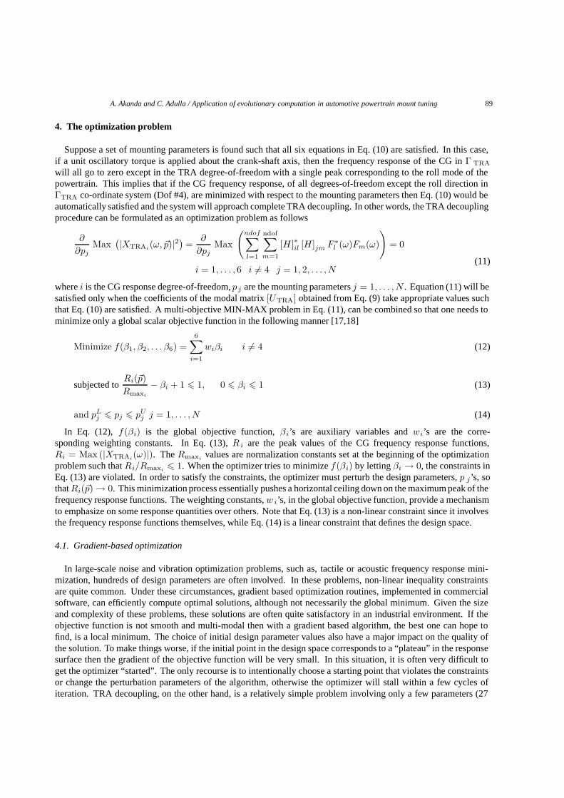
4. The optimization problem
Suppose a set of mounting parameters is found such that all six equations in Eq. (10) are satisfied. In this case,if a unit oscillatory torque is applied about the crank-shaft axis, then the frequency response of the CG in Γ TRA
will all go to zero except in the TRA degree-of-freedom with a single peak corresponding to the roll mode of thepowertrain. This implies that if the CG frequency response, of all degrees-of-freedom except the roll direction inΓTRA co-ordinate system (Dof #4), are minimized with respect to the mounting parameters then Eq. (10) would beautomatically satisfied and the system will approach complete TRA decoupling. In other words, the TRA decouplingprocedure can be formulated as an optimization problem as follows
∂
∂pjMax
(|XTRAi(ω, �p)|2) =
∂
∂pjMax
(ndof∑l=1
ndof∑m=1
[H ]∗il [H ]jm F ∗l (ω)Fm(ω)
)= 0
(11)i = 1, . . . , 6 i �= 4 j = 1, 2, . . . , N
where i is the CG response degree-of-freedom, p j are the mounting parameters j = 1, . . . , N . Equation (11) will besatisfied only when the coefficients of the modal matrix [UTRA] obtained from Eq. (9) take appropriate values suchthat Eq. (10) are satisfied. A multi-objective MIN-MAX problem in Eq. (11), can be combined so that one needs tominimize only a global scalar objective function in the following manner [17,18]
Minimize f(β1, β2, . . . β6) =6∑
i=1
wiβi i �= 4 (12)
subjected toRi(�p)Rmaxi
− βi + 1 � 1, 0 � βi � 1 (13)
and pLj � pj � pU
j j = 1, . . . , N (14)
In Eq. (12), f(βi) is the global objective function, βi’s are auxiliary variables and wi’s are the corre-sponding weighting constants. In Eq. (13), R i are the peak values of the CG frequency response functions,Ri = Max (|XTRAi
(ω)|). The Rmaxivalues are normalization constants set at the beginning of the optimization
problem such that Ri/Rmaxi� 1. When the optimizer tries to minimize f(βi) by letting βi → 0, the constraints in
Eq. (13) are violated. In order to satisfy the constraints, the optimizer must perturb the design parameters, p j’s, sothat Ri(�p) → 0. This minimization process essentially pushes a horizontal ceiling down on the maximum peak of thefrequency response functions. The weighting constants, w i’s, in the global objective function, provide a mechanismto emphasize on some response quantities over others. Note that Eq. (13) is a non-linear constraint since it involvesthe frequency response functions themselves, while Eq. (14) is a linear constraint that defines the design space.
4.1. Gradient-based optimization
In large-scale noise and vibration optimization problems, such as, tactile or acoustic frequency response mini-mization, hundreds of design parameters are often involved. In these problems, non-linear inequality constraintsare quite common. Under these circumstances, gradient based optimization routines, implemented in commercialsoftware, can efficiently compute optimal solutions, although not necessarily the global minimum. Given the sizeand complexity of these problems, these solutions are often quite satisfactory in an industrial environment. If theobjective function is not smooth and multi-modal then with a gradient based algorithm, the best one can hope tofind, is a local minimum. The choice of initial design parameter values also have a major impact on the quality ofthe solution. To make things worse, if the initial point in the design space corresponds to a “plateau” in the responsesurface then the gradient of the objective function will be very small. In this situation, it is often very difficult toget the optimizer “started”. The only recourse is to intentionally choose a starting point that violates the constraintsor change the perturbation parameters of the algorithm, otherwise the optimizer will stall within a few cycles ofiteration. TRA decoupling, on the other hand, is a relatively simple problem involving only a few parameters (27

90 A. Akanda and C. Adulla / Application of evolutionary computation in automotive powertrain mount tuning
Fig. 1. Full system finite element model of a 4WD Sport Utility Vehicle.
Fig. 2. Driveline, powertrain, and exhaust system of a 4WD Sport Utility Vehicle.
for 3-mount and 36 for 4-mount systems). The computation cost of function evaluation, is also minimal in this case.Therefore, a stochastic search algorithm, such as, evolutionary computation is expected to be far more efficient andeffective in finding the global minimum for this problem.
In this work, the TRA optimization problem defined by Eqs (12)–(14) was solved using the optimization module ofthe commercial finite element software, MSC/NASTRAN. The default algorithm of the module, “Modified Methodof Feasible Directions” [3,19], was used in all MSC/NASTRAN runs. Due to software implementation issues, itwas not possible to include both, the locations and the stiffness values of the mounts, in the same optimization run.Moreover, the software did not provide any direct way of including the euler angles (orientation) of the mounts asdesign variables. To circumvent the problem, an alternate approach, explained in the following, was developed. Thestiffness matrix of a given mount in the local coordinate system is transformed by the finite element solver before

A. Akanda and C. Adulla / Application of evolutionary computation in automotive powertrain mount tuning 91
Fig. 3. Gradient based optimization performed by MSC/NASTRAN. Normalized objective function values are plotted against number ofoptimization cycles. Hard convergence was obtained in 25 cycles.
assembly of the global [K] matrix. The transformation matrix can be expressed in terms of the euler angles, α, β,and γ, as follows
[Rα] =
⎡⎣1 0 0
0 cos(α) sin(α)0 − sin(α) cos(α)
⎤⎦
[Rβ] =
⎡⎣cos(β) 0 − sin(β)
0 1 0sin(β) 0 cos(β)
⎤⎦ (15)
[Rγ ] =
⎡⎣cos(γ) − sin(γ) 0
sin(γ) cos(γ) 00 0 1
⎤⎦
If a 3-2-1 rotation sequence is assumed then the transformation matrix can be defined as [T ] = [R γ ] [Rβ ] [Rα].The stiffness of a mount transformed to global co-ordinate system can be expressed as [k g] = [T ]T [k] [T ]. One cannow add the euler angles as auxiliary design variables for each mount and then define the transformation equationsrelating the mount stiffness values to the euler angles in MSC/NASTRAN. Instead of rotating the actual coordinatesystem, one simply subjects the local mount stiffness matrix to a “virtual rotation”. Since a rotation of the local[k] matrix will result in non-zero off-diagonal terms, these must also be included as design variables. The conceptof “virtual rotation” had to be implemented as a separate optimization run for euler angles because mount stiffnessvalues themselves were being used to update the euler angles. In summary, optimization of location, stiffness andorientation were executed sequentially.

92 A. Akanda and C. Adulla / Application of evolutionary computation in automotive powertrain mount tuning
Fig. 4. In this figure, the non-linear, discontinuos and multi-modal nature of the response surface is quite evident.
4.2. Evolutionary computation
If unlimited computer resources are available, one can always perform a stochastic search in the design spaceto find the elusive global minimum. Such an approach is impractical even for very simple objective functions dueto the size of the search space. Among many, one of the widely used stochastic search algorithms is SimulatedAnnealing [7]. The algorithm is mathematically guaranteed to converge at some point in time and it is less likelyto get stuck in local minima. The algorithm, like gradient based methods, iterates towards a single best solution.However, a very slow rate of convergence, and difficulty in choosing appropriate values for the control parameters,this algorithm appears less attractive in many applications. Evolutionary computation, in contrast, maintains apopulation of potential solutions. Inspired by the principles of natural evolution and inheritance, it applies someselection process based on the “fitness” of “individuals” and some “genetic” operators. All algorithms belongingto this class have the following features. An evolutionary algorithm is a probabilistic method which maintains apopulation of solution vectors known as “individuals” for each iteration. Each solution or individual is evaluated togive a measure of it’s “fitness”. Usually, fitness implies the value of the objective function in some form. Then anew population is formed by selecting the more fit solution vectors. The Members of the new population are thentransformed by means of “genetic” operators to form an all new population of solutions. Commonly used operatorsare recombination, mutation, cross-over etc. The selection process can be stochastic or deterministic. Three mostwidely used algorithms that fall into the category of evolutionary computation are i) Genetic Algorithm (GA), ii)Evolutionary Programming (EP) and iii) Evolutionary Strategies (ES). These algorithms differ in the type of geneticoperators used, the selection methods used, how constraints are handled, and finally, how the solution vector isrepresented (binary or floating point numbers). An overview of the most common instances of these algorithms isgiven in [4]. More advanced selection, mutation and other operators along with constraint handling techniques arediscussed in [20].
Compared to Genetic Algorithms and Evolutionary Programming, in their standard form, Evolutionary Strategieshas been shown to perform very well on multi-modal continuous function optimization problems [9]. The algorithm,in its standard form, is very easy to implement. It also provides a simple way of handling inequality constraints [8].The algorithm stochastically samples the design space to form an initial population of solution vectors. It then createsa larger population of offspring solution vectors by applying recombination and mutation operators on the parent
A. Akanda and C. Adulla / Application of evolutionary computation in automotive powertrain mount tuning 93
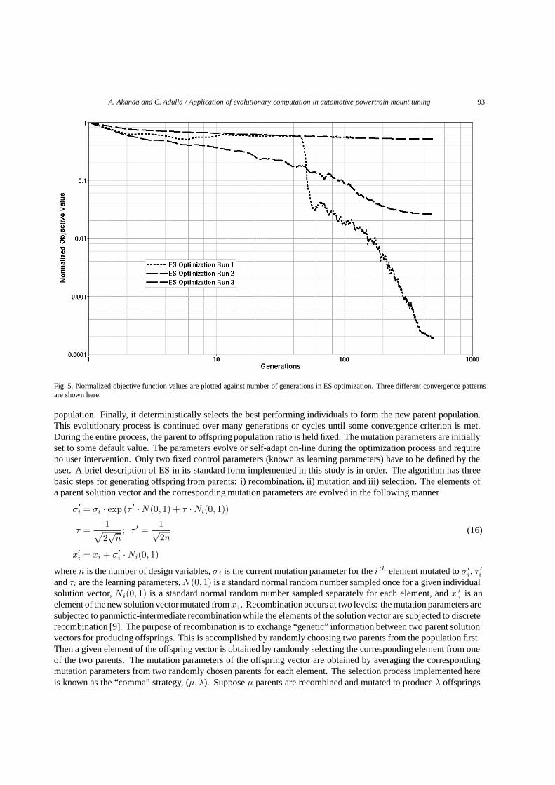
Fig. 5. Normalized objective function values are plotted against number of generations in ES optimization. Three different convergence patternsare shown here.
population. Finally, it deterministically selects the best performing individuals to form the new parent population.This evolutionary process is continued over many generations or cycles until some convergence criterion is met.During the entire process, the parent to offspring population ratio is held fixed. The mutation parameters are initiallyset to some default value. The parameters evolve or self-adapt on-line during the optimization process and requireno user intervention. Only two fixed control parameters (known as learning parameters) have to be defined by theuser. A brief description of ES in its standard form implemented in this study is in order. The algorithm has threebasic steps for generating offspring from parents: i) recombination, ii) mutation and iii) selection. The elements ofa parent solution vector and the corresponding mutation parameters are evolved in the following manner
σ′i = σi · exp (τ ′ · N(0, 1) + τ · Ni(0, 1))
τ =1√2√
n; τ ′ =
1√2n
(16)
x′i = xi + σ′
i · Ni(0, 1)
where n is the number of design variables, σi is the current mutation parameter for the i th element mutated to σ′i, τ ′
i
and τi are the learning parameters, N(0, 1) is a standard normal random number sampled once for a given individualsolution vector, Ni(0, 1) is a standard normal random number sampled separately for each element, and x ′
i is anelement of the new solution vector mutated from x i. Recombination occurs at two levels: the mutation parameters aresubjected to panmictic-intermediate recombination while the elements of the solution vector are subjected to discreterecombination [9]. The purpose of recombination is to exchange “genetic” information between two parent solutionvectors for producing offsprings. This is accomplished by randomly choosing two parents from the population first.Then a given element of the offspring vector is obtained by randomly selecting the corresponding element from oneof the two parents. The mutation parameters of the offspring vector are obtained by averaging the correspondingmutation parameters from two randomly chosen parents for each element. The selection process implemented hereis known as the “comma” strategy, (μ, λ). Suppose μ parents are recombined and mutated to produce λ offsprings
94 A. Akanda and C. Adulla / Application of evolutionary computation in automotive powertrain mount tuning
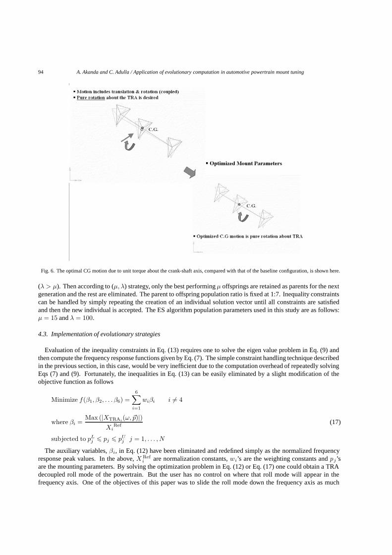
Fig. 6. The optimal CG motion due to unit torque about the crank-shaft axis, compared with that of the baseline configuration, is shown here.
(λ > μ). Then according to (μ, λ) strategy, only the best performing μ offsprings are retained as parents for the nextgeneration and the rest are eliminated. The parent to offspring population ratio is fixed at 1:7. Inequality constraintscan be handled by simply repeating the creation of an individual solution vector until all constraints are satisfiedand then the new individual is accepted. The ES algorithm population parameters used in this study are as follows:μ = 15 and λ = 100.
4.3. Implementation of evolutionary strategies
Evaluation of the inequality constraints in Eq. (13) requires one to solve the eigen value problem in Eq. (9) andthen compute the frequency response functions given by Eq. (7). The simple constraint handling technique describedin the previous section, in this case, would be very inefficient due to the computation overhead of repeatedly solvingEqs (7) and (9). Fortunately, the inequalities in Eq. (13) can be easily eliminated by a slight modification of theobjective function as follows
Minimize f(β1, β2, . . . β6) =6∑
i=1
wiβi i �= 4
where βi =Max (|XTRAi
(ω, �p)|)Xi
Ref(17)
subjected to pLj � pj � pU
j j = 1, . . . , N
The auxiliary variables, βi, in Eq. (12) have been eliminated and redefined simply as the normalized frequencyresponse peak values. In the above, X Ref
i are normalization constants, wi’s are the weighting constants and pj’sare the mounting parameters. By solving the optimization problem in Eq. (12) or Eq. (17) one could obtain a TRAdecoupled roll mode of the powertrain. But the user has no control on where that roll mode will appear in thefrequency axis. One of the objectives of this paper was to slide the roll mode down the frequency axis as much

A. Akanda and C. Adulla / Application of evolutionary computation in automotive powertrain mount tuning 95
Fig. 7. Magnitude of solution vectors, normalized with respect to that of the baseline, for ten different ES optimization runs are shown here. Thecorresponding final objective function values are also shown in the table.
as possible for maximum isolation. Another objective was to deliberately place the roll mode at or near the frontsuspension tramp mode. Neither of these two objectives can be pursued if there is no control over the roll modefrequency. Complete decoupling conditions given by Eq. (10), shows that once a decoupled roll mode is obtained,one can always scale the global [K] matrix by a constant factor α, to adjust the roll mode frequency without disturbingthe decoupling. However, scaling may not be possible in many situations as it might force some of the mountstiffness values below the production feasible lower limits. Therefore, Eq. (18) needs to be modified in some fashionto include this additional constraint. One way of enforcing such a constraint is to add a static penalty function [20]to the current objective function in the following manner
Minimize f(β1, β2, . . . β6, β7) =7∑
i=1
wiβi i �= 4
where β7 =fRoll
fTargetRoll
(18)
subjected to pLj � pj � pU
j j = 1, . . . , N
where fRoll is identified by locating the roll mode frequency corresponding to the peak of |X TRAi(ω)| in the roll
degree-of-freedom (dof i = 4), f TargetRoll is the target roll mode frequency. Note that the weighting constant, w 7 is set
to zero when the roll mode frequency becomes less than the target frequency
w7 ={
C, fRoll � fTargetRoll
0, otherwise(19)
96 A. Akanda and C. Adulla / Application of evolutionary computation in automotive powertrain mount tuning
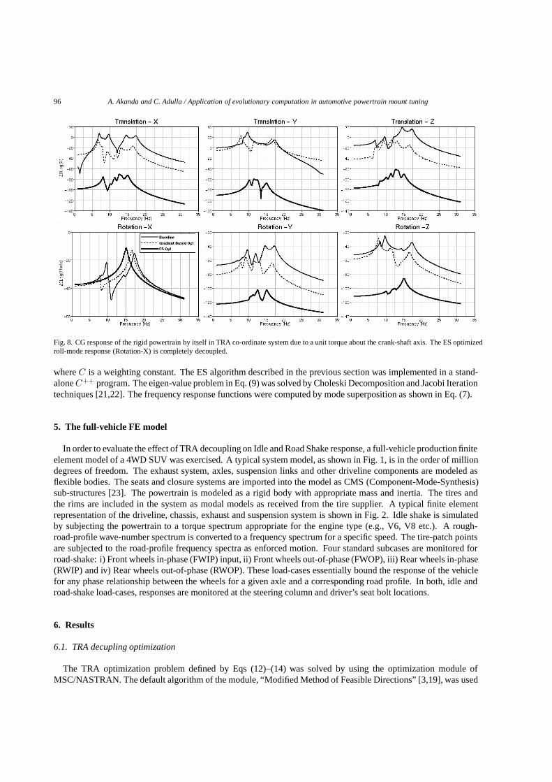
Fig. 8. CG response of the rigid powertrain by itself in TRA co-ordinate system due to a unit torque about the crank-shaft axis. The ES optimizedroll-mode response (Rotation-X) is completely decoupled.
where C is a weighting constant. The ES algorithm described in the previous section was implemented in a stand-alone C++ program. The eigen-value problem in Eq. (9) was solved by Choleski Decomposition and Jacobi Iterationtechniques [21,22]. The frequency response functions were computed by mode superposition as shown in Eq. (7).
5. The full-vehicle FE model
In order to evaluate the effect of TRA decoupling on Idle and Road Shake response, a full-vehicle production finiteelement model of a 4WD SUV was exercised. A typical system model, as shown in Fig. 1, is in the order of milliondegrees of freedom. The exhaust system, axles, suspension links and other driveline components are modeled asflexible bodies. The seats and closure systems are imported into the model as CMS (Component-Mode-Synthesis)sub-structures [23]. The powertrain is modeled as a rigid body with appropriate mass and inertia. The tires andthe rims are included in the system as modal models as received from the tire supplier. A typical finite elementrepresentation of the driveline, chassis, exhaust and suspension system is shown in Fig. 2. Idle shake is simulatedby subjecting the powertrain to a torque spectrum appropriate for the engine type (e.g., V6, V8 etc.). A rough-road-profile wave-number spectrum is converted to a frequency spectrum for a specific speed. The tire-patch pointsare subjected to the road-profile frequency spectra as enforced motion. Four standard subcases are monitored forroad-shake: i) Front wheels in-phase (FWIP) input, ii) Front wheels out-of-phase (FWOP), iii) Rear wheels in-phase(RWIP) and iv) Rear wheels out-of-phase (RWOP). These load-cases essentially bound the response of the vehiclefor any phase relationship between the wheels for a given axle and a corresponding road profile. In both, idle androad-shake load-cases, responses are monitored at the steering column and driver’s seat bolt locations.
6. Results
6.1. TRA decupling optimization
The TRA optimization problem defined by Eqs (12)–(14) was solved by using the optimization module ofMSC/NASTRAN. The default algorithm of the module, “Modified Method of Feasible Directions” [3,19], was used

A. Akanda and C. Adulla / Application of evolutionary computation in automotive powertrain mount tuning 97
Fig. 9. CG response of the powertrain in the full-vehicle FE model, due to a unit torque about the crank-shaft axis.
Fig. 10. ES optimized mount locations are compared with that of the baseline system.
in all MSC/NASTRAN runs. In this work, all MSC/NASTRAN optimization runs are referred to as Gradient-Based-Optimization. Mount location, stiffness and euler angle optimization was performed sequentially by solvingEqs (12)–(13). Production feasible bounds were imposed on all 36 mounting parameters in Eq. (14). In Fig. 3, thenormalized values of the objective function are shown as a function of optimization cycles. Hard convergence wasachieved in 25 cycles. Evolutionary Strategies (ES) was used to solve the optimization problem in Eq. (18). Theparameter bounds were exactly the same as that of MSC/NASTRAN optimization runs. Since the response surface ofthe objective function cannot be visualized in the full design space, one alternative is to vary one variable at a time and

98 A. Akanda and C. Adulla / Application of evolutionary computation in automotive powertrain mount tuning
Fig. 11. Idle shake response at the steering column in the full-vehicle system for different engine orders.
examine the cross section of the response surface. In Fig. 4, the objective function response surfaces correspondingto Eq. (18), as a function of some of the design varibles is shown. In this figure, the non-linear, discontinuos andmulti-modal nature of the response surface is quite evident. It is a common practice to run probabilistic searchalgorithms a number of times to capture as many local minima and possibly the global minimum of the objectivefunction. In this study, ES was run with exactly the same constraints ten times. All optimization runs were limitedto 500 generations. In these runs, ES exhibited different convergence patterns, most likely related to relative minimain the response surface of the objective function. Normalized objective function values for three different ES runs,capturing some of these convergence patterns, as a function of number of generations, are shown in Fig. 5. Theoptimal CG motion due to unit torque about the crank-shaft axis is compared with that of the baseline configurationin Fig. 6. Note that due to the additional constraint imposed on the roll mode frequency by adding a penalty function,one can not directly compare the objective function values from ES with that of MSC/NASTRAN. In Fig. 5, itappears that ES found two local and the global minimum. These convergence patterns show that the objectivefunction is indeed multi-modal. To graphically compare the scatter of the solution vectors in design space, first thedesign variables, pL
j � pj � pUj , were linearly scaled [24] between (−1, 1) according to the following equations
pLj � pj � pU
j
Amax = 1.0, Amin = −1.0
Rj =Amax − Amin
pUj − pL
j
(20)
p′j = Ripj +[Amin − Rjp
Lj
]−1.0 � p′j � 1.0

A. Akanda and C. Adulla / Application of evolutionary computation in automotive powertrain mount tuning 99
Fig. 12. Idle shake response at the driver’s seat bolt location in the full-vehicle system different engine orders.
The magnitude of solution vectors, P =√∑N
i=1 p2j , were then normalized with respect to that of the baseline
location in design space. In Fig. 7, these magnitudes and the corresponding best objective function values from theten runs are compared. From this plot one can conclude that the solutions obtained by ES represent different locationsin the design space. In other words, potentially, multiple local minima have been identified by ES. In order to captureall the relative minima, in short of running the algorithm N number of times, one must resort to a more sophisticatedform of the ES algorithm. Different techniques have been developed over the years to accomplish this, for example,The Sequential Niche Technique, or The Species Conserving GA, to name a few [25,26]. These techniques were notimplemented in this study. Note that the quality of solutions obtained in all ten runs were significantly better thanthat of the gradient based optimization. In order to assess the quality of the solutions, responses at two levels weremonitored: i) CG response of the rigid powertrain by itself in TRA co-ordinate system and in the full-vehicle FEmodel due to a unit torque spectrum applied about the crank-shaft axis, ii) Steering column and Seat response dueengine idle torque and road-shake input. The CG response of the rigid powertrain by itself, in the TRA co-ordinatesystem is shown in Fig. 8. Here it can be seen that the best solution obtained from ES has done significantly betterthan MSC/NASTRAN in decoupling the system. The decoupled CG response, due to a unit torque about the crank,as expected, shows a higher amplitude single peak at the roll mode. Since the system is decoupled from other modes,concentration of energy is only at the roll mode, causing the amplitude to increase from that of the baseline system.This is deemed as a desirable feature because a pure roll mode of the power-train will serve as a more effectivetuned absorber to reduced front suspension tramp related response peaks. The roll mode response (Rotation-X)produced by ES is completely decoupled, while the responses in other degrees-of-freedom are at least 70 dB belowthe baseline responses. The CG response in the full-vehicle FE model is shown in Fig. 9. Here again, it can be seenthat the solution vector obtained from ES produced a completely decoupled CG response even at the full-vehiclesystem level. This is generally difficult to achieve due to strong coupling between the powertrain, driveline and the

100 A. Akanda and C. Adulla / Application of evolutionary computation in automotive powertrain mount tuning
Fig. 13. Road shake response of the full-vehicle system at the steering column. The four loadcases were: front and rear wheels in-phase(FWIP/RWIP) and out-of-phase (FWOP/RWOP).
exhaust system. The original and optimal mount locations are shown in Fig. 10. As expected, it can be seen in thisfigure that the optimizer tried to position the mounts as symmetrically as possible about the TRA (triangles).
6.2. Idle and road shake response
The roll mode of the baseline powertrain system by itself was at 17.4 Hz. Here the mount isolators are attached tothe ground. In the full vehicle FE model, the roll frequency of the powertrain dropped down to 13.5 Hz due to thecompliance of the frame at the mount attachments, and added inertia effect of the driveline. The front suspensionhop and tramp mode of the vehicle were at 9.6 and 12.1 Hz, respectively. In order for the powertrain roll mode towork as a tuned absorber, one needs to place it at 12 Hz. Therefore, in ES optimization, a constraint of 15 Hz, onthe roll mode of the powertrain by itself, was defined so that a roll mode at 12 Hz in the full vehicle model couldbe obtained. In Fig. 9, it can be seen that the ES optimizer successfully placed the roll mode exactly at 12 Hz anddecoupled the CG response in the full vehicle model. The vehicle idle shake responses at the steering column and theseat for 1st, 1.5, 2nd, 2.5 and 3rd order of the engine are shown in Figs 11–12. The response values were normalizedwith respect to that of the baseline in both plots. The decoupled low roll solution obtained from ES, improved theidle response for all orders, particularly, 1.5 and 2nd. The objective of the optimization exercise was to improveidle quality without sacrificing road-shake performance. In Figs 13–14, the road-shake response of the vehicle atsteering column and seat bolt location are shown for the standard load cases. Except for a slight degradation in therear-wheels-out-of-phase (RWOP) loadcase, ES optimized system improved road-shake performance appreciablyfor all remaining loadcases. Figures 13–14 show that placement of the roll mode exactly at the front suspensiontramp mode significantly reduced the response due to front-wheels-out-of-phase (FWOP) loadcase.

A. Akanda and C. Adulla / Application of evolutionary computation in automotive powertrain mount tuning 101
Fig. 14. Road shake response of the full-vehicle system at the driver’s seat front-out-board (FOB) bolt location.
7. Conclusions
In this study, TRA decoupling was cast as an optimization problem so that one could obtain a decoupled roll modeof the powertrain and adjust the corresponding frequency to improve idle and road shake response of a 4 WD SUV.Both the objectives were met by implementing Evolutionary Strategies to solve a modified objective function thatnot only decouples the roll mode but also places it at desired frequency. The lower bounds of mounting parameters,were carefully chosen so that load bearing capacity and durability of the mounting system was not compromised.Under extreme conditions such as wide-open-throttle and sudden vehicle maneuvering, the mount isolator rates canbe driven to non-linear range due to large excursions. This undesirable condition, commonly referred to as “ratebuild-up” can lead to grounding of the rubber mounts rendering them useless as vibration isolators. In this study,all the mount isolator stiffness values were kept within the linear range of typical force-deflection characteristics ofproduction powertrain mounts to avoid this condition.
The Evolutionary Strategies algorithm implemented in this study, outperformed a standard gradient-based al-gorithm, in terms of robustness, ease of implementation, ability to locate multiple local minima and the globalminimum and last but not least, offer a population of feasible solutions. Since the gradient-based optimizer usedin this study was part of a commercial FE solver running on a massively parallelized supercomputer system whilethe ES optimization code was run on a stand-alone HP workstation in serial mode, performance of the algorithmscould not be directly compared. However, in either case, the final results were obtained in less than one hour. Aparallelized version of the ES code is expected to run significantly faster. As mentioned earlier, the algorithm,albeit not implemented here, can also be extended by implementing the Sequential Niche Technique, or the SpeciesConserving GA [25,26], to automatically locate all the relative minima. In general, for this problem, any of thestandard evolutionary algorithms (GA, ES or EP), is expected to perform much better than gradient based algorithms.
102 A. Akanda and C. Adulla / Application of evolutionary computation in automotive powertrain mount tuning
Acknowledgement
The authors would like to thank Mr. Suresh Nagamangala, (Supervisor, Truck NVH CAE, DaimlerChryslerCorp.), and Mr. Hamid Keshtkar, (Manager, Truck CAE, DaimlerChrysler Corp.) for their encouragement andsupport for this study.
References
[1] J.A. Cogswell and D.E. Malen, Engine mount for integral body vehicle, SAE International Congress and Exposition, Detroit, Michigan(830258), 1983.
[2] T. Jeong and R. Singh, Analytical methods of decoupling the automotive engine torque roll axis, Journal of Sound and Vibration 234(1)(2000), 85–114.
[3] K. Blackley, MSC/NASTRAN Basic Dynamic Analysis User’s Guide, The MacNeal-Schwendler Corporation, Los Angeles, CA, 1995.[4] D.B. Fogel, T. Back and Z. Michaelwicz, Evolutionary Computation 1: Basic Algorithms and Operators, (first edition), Institute of Physics
Publishing, Bristol and Philadelphia, 2000.[5] D.E. Goldberg, Genetic Algorithms in Search Optimization and Machine Learning, (first edition), Addison-Wesley Publishing Company,
Massachusetts, 1989.[6] Z. Michaelwicz, Genetic Algorithms + Data Structures = Evolution Programs, (third edition), Springer-Verlag, New York, 1999.[7] Z. Michaelwicz and D.B. Fogel, How To Solve It: Modern Heuristics, (third edition), Springer-Verlag, Berlin, 2002.[8] H.P. Schwefel, Evolution and Optimum Seeking, (first edition,), John Wiley, Chichester, UK, 1995.[9] T. Back, Evolutionary Algorithms in Theory and Practice, (first edition), Oxford University Press, Oxford and New York, 1996.
[10] A. Farshidianfar and M. Ebrahimi, Optimization of vehicle driveline vibrations using genetic algorithm (ga), SAE Noise and VibrationConference, Traverse City, Michigan, (2001-01-1502), 2001.
[11] T. Sakai, M. Iwahara, Y. Shirai and I. Hagiwara, Optimum engine mounting layout by genetic algorithm, SAE Internal Truck and BusMeeting and Exhibition, Chicago, Illinois, (2001-01-2810), 2001.
[12] D. Hartog, Mechanical Vibrations, (first edition), Dover Publishing Inc., New York, 1985.[13] C.E. Crede and C.M. Harris, eds, Shock and Vibration Handbook, (second edition), McGraw-Hill, New York, 1961.[14] C.Q. Liu, A computerized optimization method of engine mounting system, SAE Noise and Vibration Conference, Traverse City, Michigan,
(2003-01- 1461), 2003.[15] C.Q. Liu, Dynamount user’s manual, DaimlerChrysler Internal Report, 2002.[16] L. Meirovitch, Analytical Methods in Vibrations, (first edition, ), Macmillan Publishing Co., Inc., New York, 1967.[17] M. Chargin and H. Miura, A Exible Formulation for Multi-Objective Design Problems, Proceedings of The 3rd International Conference
on High Performance Computing, Cray Research Inc., 1997, 147–159.[18] J.E. Taylor and M.P. Bendsoe, An interpretation for min-max structural design problems including a method for relaxing constraints,
Internal Journal of Solids and Structures 20(4) (1984), 301–314.[19] G.N. Vanderplaats, Numerical Optimization Techniques for Engineering Design: with Applications, (first edition), McGraw-Hill, Inc.,
New York, 1984.[20] D.B. Fogel, T. Back and Z. Michaelwicz, eds, Evolutionary Computation 2: Advanced Algorithms and Operators, (first edition,), Institute
of Physics Publishing, Bristol and Philadelphia, 2000.[21] L. Meirovitch, Principles and techniques of Vibrations, ( first edition,), Prentice Hall, New Jersey, 1997.[22] W.H. Press, S.A. Teukolsky, W.T. Vetterling and B.P. Flannery, Numerical Recipes in C. Cambridge University Press, (second edition,),
New York, 1999.[23] R.R. Craig and M.C.C. Bampton, Coupling of substructures for dynamic analysis, AAIA Journal 6(7) (1968), 1313–1319.[24] T. Masters, Practical Neural Network Recipes in C++, (first edition,), Morgan Kaufmann, San Francisco, CA, 1993.[25] D. Beasley and D.R. Bull, A sequential niche technique for multimodal function optimization, Evolutionary Computation 1(2) (1993),
101–125.[26] J. Li, M.E. Balazs, G.T. Parks and P.J. Clarkson. A species conserving genetic algorithm for multimodal function optimization, Evolutionary
Computation 10(3) (2002), 207-234-125.

International Journal of
AerospaceEngineeringHindawi Publishing Corporationhttp://www.hindawi.com Volume 2010
RoboticsJournal of
Hindawi Publishing Corporationhttp://www.hindawi.com Volume 2014
Hindawi Publishing Corporationhttp://www.hindawi.com Volume 2014
Active and Passive Electronic Components
Control Scienceand Engineering
Journal of
Hindawi Publishing Corporationhttp://www.hindawi.com Volume 2014
International Journal of
RotatingMachinery
Hindawi Publishing Corporationhttp://www.hindawi.com Volume 2014
Hindawi Publishing Corporation http://www.hindawi.com
Journal ofEngineeringVolume 2014
Submit your manuscripts athttp://www.hindawi.com
VLSI Design
Hindawi Publishing Corporationhttp://www.hindawi.com Volume 2014
Hindawi Publishing Corporationhttp://www.hindawi.com Volume 2014
Shock and Vibration
Hindawi Publishing Corporationhttp://www.hindawi.com Volume 2014
Civil EngineeringAdvances in
Acoustics and VibrationAdvances in
Hindawi Publishing Corporationhttp://www.hindawi.com Volume 2014
Hindawi Publishing Corporationhttp://www.hindawi.com Volume 2014
Electrical and Computer Engineering
Journal of
Advances inOptoElectronics
Hindawi Publishing Corporation http://www.hindawi.com
Volume 2014
The Scientific World JournalHindawi Publishing Corporation http://www.hindawi.com Volume 2014
SensorsJournal of
Hindawi Publishing Corporationhttp://www.hindawi.com Volume 2014
Modelling & Simulation in EngineeringHindawi Publishing Corporation http://www.hindawi.com Volume 2014
Hindawi Publishing Corporationhttp://www.hindawi.com Volume 2014
Chemical EngineeringInternational Journal of Antennas and
Propagation
International Journal of
Hindawi Publishing Corporationhttp://www.hindawi.com Volume 2014
Hindawi Publishing Corporationhttp://www.hindawi.com Volume 2014
Navigation and Observation
International Journal of
Hindawi Publishing Corporationhttp://www.hindawi.com Volume 2014
DistributedSensor Networks
International Journal of