application of en-eurocode 8 part 1 for the seismic design ... · i application of en-eurocode 8...
TRANSCRIPT

U N I V E R S I T Y O F P A T R A S
DEPARTMENT OF CIVIL ENGINEERING
Report Series in Structural and Earthquake Engineering
APPLICATION OF EN-EUROCODE 8 PART 1
FOR THE SEISMIC DESIGN OF
MULTISTOREY CONCRETE BUILDINGS
MICHAEL N. FARDIS, GEORGIOS TSIONIS
Report No. SEE 2011-01
January 2011


i
APPLICATION OF EN-EUROCODE 8 PART 1
FOR THE SEISMIC DESIGN OF
MULTISTOREY CONCRETE BUILDINGS
by
MICHAEL N. FARDIS and GEORGIOS TSIONIS
University of Patras
The report has been prepared with the
financial support of the European Commission
under FP7 project A.C.E.S.
Any opinions, findings, and conclusions or recommendations
expressed in this material are those of the author(s)
and do not necessarily reflect those of the European Commission.
Report No. SEE 2011-01
Department of Civil Engineering, University of Patras
January 2011


iii
Abstract
The report illustrates the application of EN-Eurocodes 2 and 8 for the analysis and design
of a multi-storey concrete building for earthquake resistance. Although fairly regular, the
building has a realistic geometry, not an idealised one. It has six storeys above ground
and two basement floors, extending in one direction beyond the plan of the
superstructure. The basement is surrounded by a continuous perimeter wall, serving as a
deep foundation beam for the outer vertical elements of the building. In one of the two
main horizontal directions the structural system comprises four large walls – two at the
perimeter, two interior – rendering it a wall system. In the other direction the frames are
complemented by a single interior wall with a U-section, giving a wall-equivalent dual
system. The design peak ground acceleration on rock is 0.25g (moderate seismicity).
The analysis is carried out with computer code ETABS, using the modal response
spectrum method for the seismic action. Key feature of the model are the deep prismatic
elements representing the basement perimeter wall as a foundation beam on closely
spaced elastic supports (Winkler springs). The stiffness of the fictitious vertical members
intervening between these springs and the axis of the deep beam are chosen to reflect
the horizontal stiffness of the perimeter walls.
After giving an overview of (a) the process for detailed seismic design of concrete
buildings, as this is dictated by the interdependencies of design phases according to EN-
Eurocode 8 (mainly owing to capacity design) and (b) of the design and detailing rules in
EN-Eurocode 8 for beams, columns and ductile walls of the three Ductility Classes (DC)
in EN-Eurocode 8 (DC Low, Medium or High), the detailed design of all elements is
illustrated, from the roof to the foundation soil. The detailed design is done
“automatically”, through computational modules having as built-in the dimensioning and
detailing rules of Eurocodes 2 and 8. The modules are activated in a prescribed
sequence, such that all outcomes which are necessary as input to subsequent design
phases of the same or other elements or types of elements are archived for future use.
Examples of such information include: (a) the moment resistances at the end sections of
beams for the capacity design of the columns they frame into; (b) the moment
resistances at the ends of beams and columns for the capacity design in shear of these
elements and of the ones they frame into; (c) the cracked stiffness of beams that restrain

iv
columns against buckling; (d) the capacity design magnification factors at the base of
columns or walls for the design of their footings, etc. The design is on purpose
“minimalistic”: the reinforcement is tailored to the demands of the analysis and of EN-
Eurocodes 2 and 8, to avoid overstrengths and margins that are not absolutely needed
and would have reflected the choice of the designer rather than the Eurocodes’ intention.
It is believed that this is the first published illustration of a complete design of a
realistic multi-storey concrete building according to EN-Eurocodes 2 and 8. As such, it is
certainly open to criticism. This is more so as, unlike in analysis, there is no unique
solution in design.

v
Table of Contents
Abstract ............................................................................................................................................ iii
1 Introduction ................................................................................................................................. 1
1.1 Scope of the report ................................................................................................................ 1
1.2 Description of the building ................................................................................................... 1
2 Actions......................................................................................................................................... 7
2.1 Combination of actions for the seismic design situation ...................................................... 7
2.2 Vertical actions ..................................................................................................................... 7
2.3 Seismic action ....................................................................................................................... 7
2.4 Accidental eccentricity ......................................................................................................... 9
2.5 Storey forces for the lateral force method of analysis ........................................................ 10
3 Modelling .................................................................................................................................. 13
3.1 General ................................................................................................................................ 13
3.2 Effective flange width of beams ......................................................................................... 14
3.3 Modelling of perimeter foundation walls ........................................................................... 15
3.4 Modelling of vertical actions .............................................................................................. 16
3.5 Modelling of the foundation and the soil ............................................................................ 17
4 Analysis ..................................................................................................................................... 19
4.1 General ................................................................................................................................ 19
4.2 Modal periods, shapes and participation factors................................................................. 19
4.3 Seismic moments, shears and axial forces .......................................................................... 20
4.4 Action effects of gravity loads ............................................................................................ 22
5 Verifications and detailed design .............................................................................................. 51
5.1 Damage limitation .............................................................................................................. 51
5.2 Second-order effects ........................................................................................................... 51
5.3 ULS and SLS verifications and detailing ........................................................................... 53
5.3.1 General ......................................................................................................................... 53
5.3.2 Overview of the detailed design procedure .................................................................. 53
5.3.3 Additional information for the design of beams in bending ........................................ 59
5.3.4 Additional information for the design of columns ....................................................... 59
5.3.5 Additional information for the design of beams in shear ............................................. 60
5.3.6 Additional information for the design of walls ............................................................ 61
5.3.7 Additional information for the design of foundation beams ........................................ 61
5.3.8 Additional information for the design of footings ....................................................... 62
6 Design of beams in bending ...................................................................................................... 69
6.1 Frame A .............................................................................................................................. 69
6.2 Frame B .............................................................................................................................. 82
6.3 Frame C .............................................................................................................................. 90
6.4 Frame 1 ............................................................................................................................. 108
6.5 Frame 2 ............................................................................................................................. 114
6.6 Frame 3 ............................................................................................................................. 122
7 Design of columns ................................................................................................................... 140
7.1 Column C1 ........................................................................................................................ 140
7.2 Column C2 ........................................................................................................................ 143
7.3 Column C3 ........................................................................................................................ 147
7.4 Column C7 ........................................................................................................................ 150
7.5 Column C8 ........................................................................................................................ 155
7.6 Column C11 ...................................................................................................................... 159
7.7 Column C12 ...................................................................................................................... 163
7.8 Column C13 ...................................................................................................................... 167
8 Design of beams in shear......................................................................................................... 175

vi
8.1 Frame A ............................................................................................................................ 175
8.2 Frame B ............................................................................................................................ 181
8.3 Frame C ............................................................................................................................ 184
8.4 Frame 1 ............................................................................................................................. 192
8.5 Frame 2 ............................................................................................................................. 195
8.6 Frame 3 ............................................................................................................................. 199
9 Design of walls ........................................................................................................................ 205
9.1 Wall W1 ............................................................................................................................ 205
9.2 Wall W3 ............................................................................................................................ 209
9.3 Wall W5 ............................................................................................................................ 212
10 Design of basement perimeter walls as deep foundation beams .......................................... 219
10.1 Frame A ............................................................................................................................ 219
10.2 Frame 1 ............................................................................................................................. 222
10.3 Frame D ............................................................................................................................ 223
11 Design of foundation elements ............................................................................................ 227
11.1 Footing F7 ......................................................................................................................... 227
11.2 Footing F12 ....................................................................................................................... 228
11.3 Footing F13 ....................................................................................................................... 229
11.4 Common footing of columns C8, C9 and walls W3, W4, W5 ......................................... 230
11.5 Strip footing of frame A ................................................................................................... 231
11.6 Strip footing of frame D ................................................................................................... 237
11.7 Strip footing of frame 1 .................................................................................................... 243
REFERENCES............................................................................................................................... 249

1
1 Introduction
1.1 Scope of the report
The report illustrates the application of EN-Eurocodes 2 and 8 for the analysis and design of a
multi-storey concrete building for earthquake resistance. Altough fairly regular, the building has a
realistic geometry, not an idealised one.
After giving an overview of the process for detailed seismic design of concrete buildings and
of the design and detailing rules in EN-Eurocode 8 for beams, columns and ductile walls of the
three Ductility Classes in EN-Eurocode 8, the detailed design of all elements is illustrated, from
the roof to the foundation soil. The detailed design is done “automatically”, through computational
modules having as built-in the dimensioning and detailing rules of Eurocodes 2 and 8. The
modules are activated in a prescribed sequence, such that all outomes which are necessary as input
for subsequent design phases of the same or other elements or types of elements are archived for
future use.
The design is on purpose “minimalistic”: the reinforcement is tailored to the demands of the
analysis and of EN-Eurocodes 2 and 8, to avoid overstrengths and margins that are not absolutely
needed and would have reflected the choice of the designer rather than the Eurocodes’ intention.
It is believed that this is the first published illustration of a complete design of a realistic
multi-storey concrete building according to EN-Eurocodes 2 and 8. As such, it is certainly open to
criticism. This is more so as, unlike in analysis, there is no unique solution in design.
Where not explicitly stated, clauses refer to Part 1 of Eurocode 8 [1].
1.2 Description of the building
The examined structure is an eight-storey residential building, including two basements. A typical
section and floor plan above the basement are shown respectively in Figures 1.1 and 1.2. The
horizontal axis X is parallel to the long direction of the plan; axis Y is parallel to the short
direction. The height of the ground storey is 4.0 m, while the height of all other storeys and the

2
two basements is 3.0 m.
Structural elements are arranged on a 6×7 m grid. The perimeter columns have a rectangular
cross-section with dimensions 0.30×0.60 m at the corners and 0.30×0.70 m elsewhere. The
internal columns have a square cross-section with dimensions 0.50×0.50 m. All beams have width
bw = 0.30 m and depth hb = 0.50 m. The slabs are 0.18 m thick. Two rectangular walls, W1 and
W2, with dimensions 0.30×4.00 m are placed at the middle of the external frames in direction Y.
At the centre of the plan, two rectangular walls, W3 and W4, with dimensions 0.25×4.00 m
accommodate the staircase; a U-shaped wall, W5, with external dimensions 1.80×3.60 m and
thickness 0.25 m forms the elevator shaft.
In the two basements the building has an additional bay in direction Y, as shown in Figures
1.2 and 1.3. The cross-section dimensions of columns and beams as well as the slab thickness are
the same as for the upper storeys. A 0.30 m-thick wall runs all along the perimeter of the
basement.
The plan of the foundation is shown in Figure 1.4. Single footings with dimensions
2.0×2.0×0.7 (width×depth×height in meters) are used for the interior columns. A common footing
with dimensions 7.0×9.0×0.8 is used for columns C8 and C9 and walls W3, W4 and W5. A strip
footing with width 1.0 m and height 0.30 m is used for the perimeter walls. Instead of a system of
two-way tie-beams, horizontal connection of the footings and the foundation strip of the basement
perimeter walls is provided by a foundation slab cast right below the top of the footings and the
perimeter foundation strip (see clause 5.4.1.2 para. (2), (3) and (7) of EN 1998-5:2004). This slab
serves also as floor of the lower basement and helps create a rigid-box foundation system together
with the perimeter walls and the slab at the roof of the upper basement.

3
Fig. 1.1 Typical floor plan above the basement
Fig. 1.2 Section in the Y direction
A
B
D
1 2 3 4 5 6
C
SLAB
ABD C
SCHEMATIC SECTION

4
Fig. 1.3 Plan of the basement
Fig. 1.4 Plan of the foundation
A
B
D
1 2 3 4 5 6
C
SLAB
A
B
D
1 2 3 4 5 6
C
FOUNDATION

5
The geometry originates from the example building prepared for the Lisbon workshop
“Eurocode 8: Seismic design of buildings”, organised by the European Commission (February
2011), but a wide range of modifications were introduced, in the geometry and the modelling.
Differences in the geometry include:
Beams are now 0.3 m wide, to better accommodate the longitudinal reinforcement at
supports, in view of the large concrete cover of the reinforcement;
The corner columns have a 0.30×0.60 m section, to meet the rule in clause 5.4.1.2.1(2) of
Eurocode 8 for an eccentricity between the axis of a beam and the supporting column not
more than 25% of the parallel column dimension.
For the analysis and design of the building the following specifications apply:
the structure is an ordinary building belonging to Importance Class II, according to the
classification in clause 4.2.5(4);
the building is designed for reference peak ground acceleration agR = 0.25 g and for
medium ductility (DCM);
the vertical component of the seismic action is ignored;
the dead load for partitions and finishings (additional to the self-weight) is 2 kN/m2; the
live load is also 2 kN/m2;
concrete C25/30 and steel S500 of Class C are used;
exposure class is XC3 giving a nominal concrete cover of 35 mm;
the soil is clay with design value of undrained shear strength cud = 300 kPa (reduced by
10% to cud = 270 kPa for the seismic design situation), design value of friction angle δd =
20o and design value of drained cohesion cd = 50 kPa; it corresponds to Ground type B for
the purposes of the definition of the seismic action at the top of the ground.
the masonry infills are ignored as far as the seismic response and design ar concerned.
Section 4.2.3 of Eurocode 8 [4] prescribes detailed criteria for structural regularity in plan and
in elevation. The classification of a building as regular or irregular affects the type of structural

6
model and analysis allowed and also the value of the behaviour factor. The verifications regarding
regularity in plan (namely the approximate symmetry about two orthogonal axes, the compactness
of the shape of the plan, the magnitude of the eccentricities between the centres of mass and
stiffness, and the relative magnitude of the radius of gyration and of the torsional radii at each
floor) are all met. The same applies for the criteria for regularity in elevation regarding the
variation of the mass, stiffness and plan dimensions from storey to storey. It is worth pointing out
in this connection that the large difference in stiffness and in plan dimensions between the two
rigid basements and the six floors above ground does not count for the characterisation of the
building as regular or not in elevation: regularity in elevation is a pre-requisite for the applicability
of the lateral force analysis procedure of clause 4.3.3.2 of EN 1998-1:2004; that clause makes
several references (e.g., para. 4.3.3.2.2(3) and 4.3.3.2.3(3)) to buildings with a rigid basement as
being within its scope. So, the building is characterised as regular both in plan and in elevation.

7
2 Actions
2.1 Combination of actions for the seismic design situation
According to clause 6.4.3.4(2) of EN 1990 [1], the combination of actions ∑Gk,j “+” AEd “+” ∑ψ2,i
Qk,i applies in the seismic design situation, where G corresponds to the self-weight of the structure
and any additional dead load, AEd denotes the seismic action, Q stands for the live loads and ψ2,i is
the partial factor for the quasi-permanent value of variable action i. The recommended value ψ2 =
0.3 for residential/office areas is used, as in Table A1.1 of EN 1990 [1].
2.2 Vertical actions
Vertical actions consist of permanent, G, and variable, Q, loads. Permanent loads comprise the
self-weight of the structure and additional 2 kN/m2 to account for finishings, partitions, etc. The
self-weight is calculated on the basis of the geometry and the concrete density, γ = 25 kN/m3 for
normal concrete including normal percentage of reinforcing steel according to Table A.1 of
Eurocode 1 [2]. Regarding variable loads, the value recommended in clause 6.3.1.2(1) of
Eurocode 1, is used: for Category A (i.e. domestic/residential use in clause 6.3.1.1(1) of Eurocode
1), the variable load on floors is qk = 2 kN/m2.
2.3 Seismic action
The seismic action is described by the elastic response spectrum of Type 1 and for Ground type B,
as in clauses 3.2.2.2(1) and 3.2.2.2(2) of Eurocode 8 [4]. The recommended values S = 1.2, TB =
0.15 sec, TC = 0.5 sec and TD = 2.0 sec are used. The reference peak ground acceleration is αgR =
0.25 g and the design peak ground acceleration is αg = γI αgR = 1.0×0.25g = 0.25g, where, from
clause 4.2.5(5), the importance factor is γI = 1.0 for Importance Class II.
The analysis is performed based on the design response spectrum, for which the value of the
behaviour factor q has to be calculated depending on the structural system and Ductility Class
according to clause 5.2.2.2. In clause 5.1.2(1), structural systems are classified on the basis of the
8
percentage of total shear force taken by the walls for the seismic design situation Vbase,wall / Vbase,tot.
The base shears were calculated from the analysis according to the lateral force method (see
section 2.5 of this report); the analysis results give:
- Vbase,wall / Vbase,tot = 63.7% in direction X and
- Vbase,wall / Vbase,tot = 91.4% in direction Y.
Then, the building is classified as wall-equivalent dual system in direction X and as wall system in
direction Y. According to clause 5.2.2.2(2), the corresponding basic values of the behaviour factor
are:
- qox = 3.0αu/α1 = 3.0×1.2 = 3.6 (for wall-equivalent dual systems clause 5.2.2.2(5) gives a
default value of αu/α1 = 1.2), and
- qoy = 3.0.
In clause 5.2.2.2(1), the value of the behaviour factor to be used in the analysis is q = qo kw,
where kw reflects the prevailing failure mode in structural systems with walls and, according to
clause 5.2.2.2(11), is calculated as kw = (1 + αo) / 3 ≤ 1.0 for wall and wall-equivalent systems.
The prevailing aspect ratio of the walls is given in clause 5.2.2.2(12) as αo =∑hwi / ∑lwi, where hwi
and lwi are respectively the height and the length of wall i.
- In direction X only wall W1 is considered and it is αox = 25.0/3.60 = 6.9 and kwx =
(1+αoX)/3 = (1+6.9)/3 = 2.6,
- In direction Y all walls are considered and it is αoy = 6×25.0/[2×(4.0+4.0+1.8)] = 7.7 and
kwy = (1+αoY)/3 = (1+7.7)/3 = 2.9; then αox = αoy = 1.0.
Finally, the behaviour factors are calculated as:
- qx = qox kwx = 3.6×1.0 = 3.6
- qy = qoy kwy = 3.0×1.0 = 3.0
The elastic and the design response spectra in the two directions are shown in Figure 2.1.

9
Fig. 2.1 Elastic and design response spectra for 5% damping
2.4 Accidental eccentricity
In order to account for uncertainties in the location of masses and in the spatial variation of the
seismic motion and according to clause 4.3.3.3.3(1), accidental torsional effects are determined as
the effects resulting from the application of static torsional moments Mai = eai Fi about the vertical
axis of each storey i, where eai is the accidental eccentricity of storey mass i and Fi is the
horizontal force acting on storey i. The horizontal forces Fi are the storey forces used for the
lateral force method analysis (see section 2.5) and the accidental eccentricity is defined in clause
4.3.2(1) as eai = 0.05 Li, where Li is the floor dimension perpendicular to the direction of the
seismic action. Torsional moments in the two directions are combined according to the SRSS rule,
MSRSS = (Mx2 + My
2)0.5
. The detailed calculations are shown in Table 2.1.
Table 2.1: Calculation of torsional moments for accidental torsional effects
Storey Fx (kN) Fy (kN) ex (m) ey (m) Mx (kNm) My (kNm) MSRSS (kNm)
roof 622 933 0.715 1.515 444.75 1413.56 1482
5 548 822 0.715 1.515 392.05 1246.06 1306
4 446 668 0.715 1.515 318.54 1012.43 1061
3 343 514 0.715 1.515 245.03 778.79 816
2 240 360 0.715 1.515 171.52 545.15 571
1 141 212 0.715 1.515 101.04 321.14 337
0.0
0.2
0.4
0.6
0.8
0 1 2 3 4
Spe
ctra
l acc
ele
rati
on
(g)
Period (sec)
Se(T)
Sd,x(T)
Sd,y(T)

10
2.5 Storey forces for the lateral force method of analysis
Following clause 4.3.3.2.2(1), the seismic base shear force is Fb = λ m Sd(T1), where Sd(T1) is the
ordinate of the design spectrum at the fundamental period of vibration, T1, of the building in the
direction considered, m is the total mass of the building above the top of the basement and λ is a
correction factor taken as λ = 0.85 if T1 < 2 TC and the building has more than two storeys, or λ =
1.0 otherwise. The fundamental periods in the two main directions are taken from the modal
analysis (see chapter 4) as:
- T1x = 0.85 sec and
- T1y = 0.68 sec.
For TC ≤ T1 ≤ TD, the ordinate of the design spectrum is Sd(T1) = αg S 2.5 (Tc/T1)/q. In particular
- in direction X it is Sd(T1x) = 0.25 g×1.2×2.5×0.50/0.85/3.6 = 0.12 g and
- in direction Y it is Sd(T1y) = 0.25g×1.2×2.5×0.50/0.68/3.0 = 0.18 g.
The total mass of the building is calculated by taking into account the masses associated with
all gravity loads appearing in the combination of actions ∑Gk,j "+" ∑ψE,i Qk,im where ψE,i = φ ψ2,i is
the combination coefficient for variable action i. The recommended values of clause 4.2.4(2) are
used, φ = 1 for the roof and φ = 0.5 for the remaining storeys.
Using the values calculated above, the total base shear in the two main horizontal directions is
Fbx = λ m Sd(T1x) = 0.85×22939×0.12 = 2340 kN and
Fby = λ m Sd(T1y) = 0.85×22939×0.18 = 3510 kN.
Assuming that the fundamental mode shape is approximated by horizontal displacements
increasing linearly along the height, as in clause 4.3.3.2.3(3), the horizontal forces Fi are taken as
Fi = Fb zi mi / ∑zj mj, where zi and zj are the heights of the masses mi and mj above the top of the
rigid basement. The detailed calculation of the storey forces used for the static calculation of the
effects of the accidental eccentricities is given in Table 2.2.

11
Table 2.2: Calculation of storey forces for the lateral force method of analysis
Storey zi mi (kN) zi×mi Fi/Fb Fx (kN) Fy (kN)
roof 19 3661 69553 0.27 622 933
5 16 3832 61311 0.23 548 822
4 13 3832 49816 0.19 446 668
3 10 3832 38320 0.15 343 514
2 7 3832 26824 0.10 240 360
1 4 3950 15802 0.06 141 212
total 22939 261625 1 2340 3510
The storey forces Fx and Fy were multiplied by the associated accidental eccentricities ex and
ey (equal to 5% of the storey dimension at right angles to the direction of the force); the resulting
torques, Fxex and Fyey, were combined according to the SRSS rule into single torques per floor,
√[(Fxex)2+(Fyey)
2], which were then statically applied to the model. The outcome of the analysis
reflects the combined effect of the accidental eccentricities of the two horizontal components of
the seismic action, to be superimposed to the combined effect of the two translationa components.


13
3 Modelling
3.1 General
According to clause 4.2.3.1(3) and because the structure is regular in plan, a simplified planar
structural model may be used. However, a three-dimensional model of the building was created
using the structural analysis software ETABS [5] and following the requirements of section 4.3.1
of Eurocode 8 [4]. In particular:
all structural members were modelled as linear elements;
the elastic flexural and shear stiffness of elements was taken equal to half the
corresponding stiffness of the uncracked element;
in order to account for the contribution of joint regions to the deformability of the building,
the length of the beam elements inside the joints was taken as rigid – this was not done for
columns so as not to overestimate the global stiffness;
floors were considered to act as rigid diaphragms; the masses and the moments of inertia of
each floor were lumped at its centre of gravity;
the masses were calculated from the gravity loads corresponding to the combination of
actions ∑Gk,j "+" ∑ψE,i Qk,im.
As pointed out in Section 1.2, the building geometry originates from that of the example
building prepared for the Lisbon workshop “Eurocode 8: Seismic design of buildings”, organised
by the European Commission (February 2011). Besides the modifications in the geometry, there
are important differences in the modelling as well:
Rigid are considered all ends of beams framing into either columns or walls, and not only
into the strong direction of walls.
The compliance of the foundation soil is explicitly included and the foundation elements
are not considered fixed to the ground; this allows computing the action effects in the
perimeter walls of the basement (which are unknown, if these walls are fixed to the ground
all-along their length) and realistically estimating the soil reactions under footings –

14
including those shared by more than one vertical element.
A different effective slab width is considered for each beam span, as highlighted in the
following section.
3.2 Effective flange width of beams
The effective width of the beam flanges was calculated according to clauses 5.3.2.1(2) and
5.3.2.1(3) of Eurocode 2 [3]. Different expressions are provided for the supports and the span, but
for structural analysis it is allowed to use for the whole beam the values for the span section. The
effective flange width for a T or L beam is beff = ∑beff,i + bw ≤ b, where beff,i = 0.2 bi + 0.1lo ≤ 0.2lo
and beff,i ≤ bi, the sum extends to the two sides of the beam, bw is the width of the beam, bi is half
the distance of adjacent beams, lo = 0.7l2 for the span section and l2 is the beam span. For the
beams of the example building the value 0.2lo is governing; so, for the beams along the X-axis it is
beff,i = 0.2×0.7×6.0 ≈ 0.85 m and for those along the Y-axis it is beff,i = 0.2×0.7×7.0 ≈ 1.0 m. The
cross-sections of the beams used in the structural model are shown in Figure 3.1.
Fig. 3.1 Effective width of beams for the structural analysis

15
The slab reinforcement within the effective flange width beff is taken into account for the
calculation of the bending resistance of the beams. For this purpose alone, and following clause
5.4.3.1.1(3), the effective width of beams framing into columns is taken equal to the width bc of
the column increased by 2hf or 4hf on each side of the beam for beams framing respectively into
exterior or interior columns, where hf is the slab thickness. These values are used only in the
design phase and not for the analysis model.
3.3 Modelling of perimeter foundation walls
The internal forces (moments and shears) in the perimeter foundation wall cannot be estimated, if
fixity to the ground is assumed there. To circumvent this problem, vertical springs have been
introduced at the underside of all foundation elements, with a value of the subgrade reaction
modulus of 250/b (kN/m), a value consistent with the soil parameters and as a common average
value for static and seismic loading conditions. Besides, a common footing has been provided
under the two internal walls in the Y direction (W3, W4), the U-shaped one (W5) and two nearby
columns (C8, C9).
The perimeter wall is modelled as a prismatic member with cross-sectional depth and
thickness those of the basement wall and top and bottom flanges – about – consistent with the
effective width of the top slab of the basement and the strip footing of the perimeter wall. The
vertical members running through the depth of the basement should represent the horizontal
stiffness of the perimeter wall. The main problem with concentrating that stiffness to a few
vertical members right underneath the vertical members of the superstructure, is a big jump in the
moment diagram of the horizontal beam modelling the perimeter basement wall as a deep
foundation beam. So, a fairly large number of fictitious vertical members running through the
depth, H = 6.3 m, of the basement wall should be introduced.
The centroidal axis of the horizontal beam modelling the perimeter basement wall as a deep
foundation beam is placed at Level 0 (ground level). This was found to be the best way to avoid

16
erroneous analysis results for the bending moments at the base of the vertical members framing
into this deep horizontal member (notably for the two exterior walls W1 and W2 in the Y-
direction). Nodes are introduced every 1.0 m along it. Each node is connected to a soil node
underneath (at Level -2) via a fictitious vertical member running through the depth H of the
basement. The cross-section of that member is such that the horizontal stiffness of the basement
wall is reproduced. The vertical soil springs, placed every 1 m, have a stiffness of 250×1 = 250
kN/m.
3.4 Modelling of vertical actions
The self-weight of the slab and beams was treated as uniform surface load on the floor. The
uniform surface loads due to G and Q were distributed as uniform loads along the beams and as
concentrated loads on walls W3, W4 and W5 according to the tributary areas schematically shown
in Figure 3.2.
Fig. 3.2 Tributary areas for vertical actions
A
B
D
1 2 3 4 5 6
C

17
The self-weight of vertical elements was calculated internally by the analysis software and
included in the permanent actions.
The permanent and variable loads on the floor at Level 0 were applied as concentrated loads
on the vertical elements that are positioned at the intersection of the perimeter with the main frame
axes (A to D and 1 to 6 in Figure 3.2). The loads due to G and Q on the floor at Level -1 were
applied as distributed loads on the beam elements used to model the perimeter basement walls.
The self-weight of the perimeter walls was also applied as distributed load on these elements.
3.5 Modelling of the foundation and the soil
In order to account for the compliance of the soil, spring elements were introduced at the nodes of
Level -2. Uniaxial springs in the vertical direction and rotational springs in the two horizontal
directions were placed at the nodes of the individual column footings. The stiffness of the vertical
and rotational springs was calculated as kv = 500 MN/m and kφ = 625 MNm/rad, assuming a
saturated clay. Only vertical deformation springs with kv = 250 MN/m were placed at the nodes of
the strip footings below the perimeter walls.
As mentioned previously, a common footing was used for walls W3, W4 and W5 together
with columns C8 and C9. The nodes at the base of these elements were connected to the node at
the centre of the footing through fairly rigid linear elements. Springs were placed at the node at the
centre of the footing. There stiffness was calculated to be: kv = 2250 MN/m in the vertical
direction and kφx=31000 MΝm/rad, kφy = 22000 MΝm/rad for rotation along the two horizontal
directions.
All nodes of the foundation were taken at the horizontal level of the underside of the strip
footing of the perimeter walls (the small difference with the elevation of the underside of the
interior footings was ignored). All foundation nodes were fixed against translation in both
horizontal directions and for rotation about the vertical.


19
4 Analysis
4.1 General
As the building is regular in elevation, clause 4.2.3.1(3) allows performing the analysis for the
calculation of the seismic action effects with the lateral force method. A modal response spectrum
analysis was carried out instead.
4.2 Modal periods, shapes and participation factors
The first three mode shapes of the building are schematically shown in Figure 4.1. The first mode
with T1 = 0.86 sec is translational along the X-axis, the second with T2 = 0.69 sec is translational
along the Y-axis and the third with T3 = 0.49 sec is torsional.
T1 = 0.86 sec
T2 = 0.69 sec
T3 = 0.49 sec
Fig. 4.1 The first three modes of the building

20
Table 4.1: Modal analysis: periods and participating masses
Mode Period (sec) mx (%) my (%)
1 0.86 53.3 0.0
2 0.68 0.0 53.5
3 0.49 0.1 0.0
4 0.22 11.4 0.0
5 0.16 0.0 21.1
6 0.12 0.3 0.0
7 0.10 6.2 0.0
8 0.08 0.0 17.8
9 0.07 15.9 0.0
10 0.06 3.8 0.0
total: 91.1 92.3
The periods and corresponding effective modal masses for the first vibration modes are listed
in Table 4.1, where it is shown that ten modes are necessary to satisfy the requirements of clause
4.3.3.3.1(3) regarding the number of modes of vibration to take into account in the analysis.
Nevertheless, all 24 modes were taken into account in the analysis.
Following clause 4.3.3.3.2(1), vibration modes may be considered independent of each other
if their periods Ti and Tj, with Ti ≥ Tj, satisfy the condition Tj ≤ 0.9 Ti. This condition is not
satisfied for a few higher modes not shown in Figure 4.1 and for this reason, the “Complete
Quadratic Combination” of modal responses was adopted.
4.3 Seismic moments, shears and axial forces
A different design response spectrum was specified in the two main horizontal directions, as given
in Figure 2.1. A single modal response spectrum analysis was performed for the two horizontal
components of the seismic action, and - following clause 4.3.3.5.1(2b) - the maximum value of
each action effect due to the two simultaneous horizontal components was obtained as the square
root of the sum of the squared values of the action effect due to each component.

21
The action effects resulting from the modal response spectrum analysis are plotted in the
following. In particular, Figures 4.2 to 4.8 show the in-plane seismic shear forces and bending
moments for the frames. The in-plane seismic shears and moments for wall W3 are given in
Figure 4.9, while Figures 4.10 and 4.11 show the shear forces and bending moments of wall W5
parallel to axes X and Y respectively. Finally, Figures 4.12 to 4.17 present the seismic axial forces
for the frames.
Because of symmetry of the building in plan, results are plotted only for frames A, B and C
along the X-axis, frames 1, 2 and 3 along the Y-axis and for wall W3.
Frame A in Figure 4.2 and Frame 1 in Figure 4.6 include the 6.3 m-deep foundation beam
modelling perimeter walls of the basement, while Frame D in Figure 4.5 comprises just that
foundation beam (it is the counterpart of the foundation beam of Frame A across the plan, but
without the frame of the superstructure). The centroidal axis of the foundation beam is at Level 0
(ground level, 3rd
level from the bottom); the moments and shears of these beams are depicted at
that level; moments and shears below that level are fictitious: they belong to the 6.3 m-tall vertical
members introduced at 1 m centres to connect the centroidal axis of the foundation beam to the
soil nodes at Level -2. The seismic moments and shears along the foundation beam of Frame A (in
Figure 4.2) are partly due to the seismic action component orthogonal to Frame A (i.e., in the Y-
direction); a major part of the overturning moment due to that component is transferred to the
ground by that foundation beam through bearing pressures distributed fairly uniformly along its
length. The seismic moments and shears along the foundation beam of Frame D (in Figure 4.5) are
almost exclusively due to the overturning moment of the seismic action component in the Y-
direction. By contrast, the seismic moments and shears along the foundation beam of Frame 1 (in
Figure 4.5) are almost fully due to the in-plane seismic action component (in the X-direction) and
are controlled by the transfer of the large moment of wall W1 to the ground through that
foundation beam.
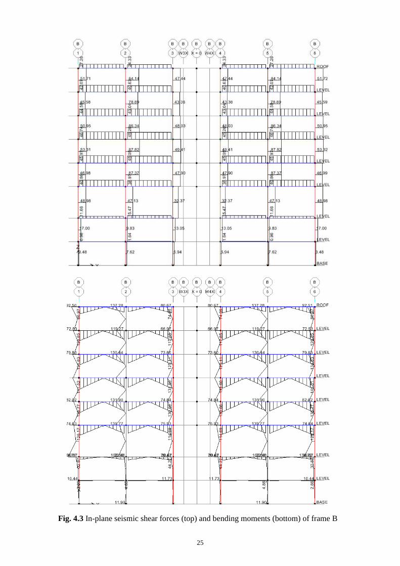
Witness in Figures 4.3, 4.4 and 4.7, 4.8, the very small magnitude of seismic moments and

22
shears in the beams and columns of the two basement floors, as in those floors the full seismic
action is transferred downwards by the large in-plane stiffness of the perimeter walls. Witness also
in Figures 4.2 to 4.4 the approximately constant magnitude of seismic moments and shears in the
various storeys of the same column or in the same bay of the various floors and their increase from
the ground level to the roof in Figures 4.6 to 4.9 (as the building is a wall system in that direction).
It is also interesting to note that the maximum seismic moments and shears in the beams and
columns of the same frame occur in general at roof level and the smallest ones at the ground floor.
This presages a similar trend for the beam flexural reinforcement.
Witness also in Figures 4.9 to 4.11 the very large seismic shears that walls W3 and W5
develop within the two basement storeys, especially in the upper one. As suggested by the reversal
of the trends in the bending moment digrams of these walls at Level 0 (i.e., at the top of the
basement), these shears have the opposite sense and sign relative to the wall shears in the
superstructure. They reflect the horizontal forces exerted on the wall by the horizontal diaphragms
at the top of the basement and at the level of foundation – and vice-versa – that create the couple
which fixes these walls to the box-type foundation of the building.
Note that the outcomes of modal analysis and the SRSS combination of the effects of the two
horizontal components of the seismic action produce only the absolute values of peak seismic
action effects. Therefore, the results in Figures 4.2 to 4.17 represent envelopes, to be
superimposed to the absolute values of the corresponding results of the static analyses for the
torsional effect of the accidental eccentricites (not shown here, for the sake of brevity). The sum of
these absolute values is superimposed then, with plus and minus sign, to the effects of the quasi-
permanent gravity actions which are considered concurrent with the seismic and included in the
seismic design situation. These latter gravity action effects are illustrated next.
4.4 Action effects of gravity loads
Separate static analyses were performed for the calculation of the action effects due to the

23
permanent, G, and variable, Q, vertical actions. There results were combined according to Eqs.
(6.10a), (6.10b) of EN 1990:2002 for the “persistent and transient design situation” and into the
“quasi-permanent” combination G + 0.3 Q which is considered to act concurrently with the design
seismic ction in the “seismic design situation”.
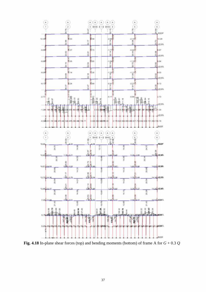
The analysis results for the “quasi-permanent” combination G + 0.3 Q are depicted in Figures
4.18 to 4.35. They do have signs and are superimposed with these signs to the seismic action
effect envelopes in Figures 4.2 to 4.17 (as well as the results of the static analyses for the torsional
effect of the accidental eccentricites) with plus and minus signs.

24
Fig. 4.2 In-plane seismic shear forces (top) and bending moments (bottom) of frame A
25
Fig. 4.3 In-plane seismic shear forces (top) and bending moments (bottom) of frame B

26
Fig. 4.4 In-plane seismic shear forces (top) and bending moments (bottom) of frame C

27
Fig. 4.5 In-plane seismic shear forces (top) and bending moments (bottom) of frame D

28
Fig. 4.6 In-plane seismic shear forces (top) & bending moments (bottom) in frame 1 and Wall W1

29
Fig. 4.7 In-plane seismic shear forces (top) and bending moments (bottom) of frame 2

30
Fig. 4.8 In-plane seismic shear forces (top) and bending moments (bottom) of frame 3

31
Fig. 4.9 In-plane seismic shear forces (top) and bending moments (bottom) of wall W3

32
Fig. 4.10 Seismic shear forces (top) and bending moments (bottom) of wall W5 in X-plane

33
Fig. 4.11 Seismic shear forces (top) and bending moments (bottom) of wall W5 in Y-plane

34
Fig. 4.12 Seismic axial forces in frame A
Fig. 4.13 Seismic axial forces in frame B

35
Fig. 4.14 Seismic axial forces in frame C
Fig. 4.15 Seismic axial forces in frame 1

36
Fig. 4.16 Seismic axial forces in frame 2
Fig. 4.17 Seismic axial forces of frame 3
37
Fig. 4.18 In-plane shear forces (top) and bending moments (bottom) of frame A for G + 0.3 Q

38
Fig. 4.19 In-plane shear forces (top) and bending moments (bottom) of frame B for G + 0.3 Q

39
Fig. 4.20 In-plane shear forces (top) and bending moments (bottom) of frame C for G + 0.3 Q

40
Fig. 4.21 Shear forces (top) and bending moments (bottom) of frame D for G + 0.3 Q

41
Fig. 4.22 In-plane shear forces (top) and bending moments (bottom) of frame 1 for G + 0.3 Q

42
Fig. 4.23 In-plane shear forces (top) and bending moments (bottom) of frame 2 for G + 0.3 Q

43
Fig. 4.24 In-plane shear forces (top) and bending moments (bottom) of frame 3 for G + 0.3 Q

44
Fig. 4.25 In-plane shear forces (top) and bending moments (bottom) of wall W3 for G + 0.3 Q

45
Fig. 4.26 Shear forces (top) and bending moments (bottom) of wall W5 in X-axis for G + 0.3 Q

46
Fig. 4.27 Shear forces (top) and bending moments (bottom) of wall W5 in Y-axis for G + 0.3 Q

47
Fig. 4.28 Axial forces of frame A for G + 0.3 Q
Fig. 4.29 Axial forces of frame B for G + 0.3 Q
48
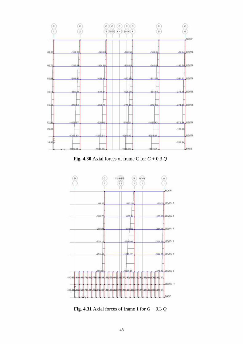
Fig. 4.30 Axial forces of frame C for G + 0.3 Q
Fig. 4.31 Axial forces of frame 1 for G + 0.3 Q

49
Fig. 4.32 Axial forces of frame 2 for G + 0.3 Q
Fig. 4.33 Axial forces of frame 3 for G + 0.3 Q

50
Fig. 4.34 Axial forces of wall W3 for G + 0.3 Q
Fig. 4.35 Axial forces of wall W5 for G + 0.3 Q

51
5 Verifications and detailed design
5.1 Damage limitation
According to clause 4.4.3.2(1) and in order to satisfy the “damage limitation requirement”, the
interstorey drift ratio, δrν/h, should be limited to certain values depending on the nature on non-
structural elements:
- 0.005 for buildings with brittle non-structural elements attached to the structure;
- 0.075 for buildings with ductile non-structural elements and
- 0.01 for buildings without non-structural elements or with non-structural elements that do
not interfere with the structural deformations.
For the drift verifications δr is the design interstorey drift, h is the storey height and ν is a
reduction factor which takes into account the lower return period of the seismic action associated
with the damage limitation requirement; according to clause 4.4.3.2(2) ν has the recommended
value ν = 0.5 for Importance Class II.
Following clause 4.3.4(1), the storey displacements, ds = qd de, used for the calculation of the
design interstorey drift are those obtained from the elastic analysis, de, multiplied by the
displacement behaviour factor, qd, which is taken equal to q. The detailed calculation of
interstorey drift ratioaccording to this procedure is given in Table 5.1. The displacements at the
storey centre of mass were considered. The height-wise distribution of drift ratio shown in Figure
5.1, shows that the strictest requirement for buildings with brittle non-structural elements is met.
5.2 Second-order effects
According to clause 4.4.2.2(2), second-order effects may be neglected if the interstorey drift
sensitivity index, θ, is less than 0.10 in all storeys. This index is calculated as θ = Ntotdr/(Vtoth),
where Ntot is the total gravity load considered in the seismic design situation, dr is the design
interstorey drift, Vtot is the total seismic storey shear and h is the storey height. In the detailed
calculations shown in Table 5.2, Ntot is defined based on the storey masses mi in Table 2.1, dr is

52
taken from Table 5.1 and Vtot is taken from the results of the modal response spectrum analysis. In
all storeys it is verified that θx ≤ 0.10 and θy ≤ 0.10. Therefore second-order effects are neglected.
Fig. 5.1 Interstorey drift ratio for the damage limitation verification
Table 5.1: Calculation of interstorey drift ratio
Storey deX (m) deY (m) dsX (m) dsY (m) δrXν/h (%) δrYν/h (%)
Roof 0.031 0.031 0.110 0.098 0.258 0.277
5 0.026 0.026 0.095 0.082 0.294 0.288
4 0.021 0.020 0.077 0.064 0.306 0.293
3 0.016 0.015 0.059 0.047 0.324 0.272
2 0.011 0.010 0.039 0.030 0.300 0.235
1 0.006 0.005 0.021 0.016 0.243 0.152
0 0.001 0.001 0.002 0.004 0.012 0.032
-1 0.000 0.001 0.001 0.002 0.018 0.037
-10
-5
0
5
10
15
20
0.0 0.1 0.2 0.3 0.4
Heig
ht (m
)
Drif t ratio (%)
direction X
direction Y

53
Table 5.2: Calculation of interstorey drift sensitivity coefficient
Storey Ptot (m) VtotX (m) VtotY (m) dsX (m) dsY (m) h (m) θX θY
Roof 3661 822 1238 0.0077 0.0083 3.0 0.011 0.008
5 7493 1309 1999 0.0088 0.0086 3.0 0.017 0.011
4 11325 1701 2532 0.0092 0.0088 3.0 0.020 0.013
3 15157 1995 2988 0.0097 0.0082 3.0 0.025 0.014
2 18989 2258 3367 0.0090 0.0070 3.0 0.025 0.013
1 22939 2455 3668 0.0097 0.0061 4.0 0.023 0.010
0 30172 2722 4042 0.0004 0.0010 3.0 0.001 0.002
-1 36225 3002 4311 0.0005 0.0011 3.0 0.002 0.003
5.3 ULS and SLS verifications and detailing
5.3.1 General
Clause 4.4.2.1(1) prescribes the conditions regarding resistance, ductility, equilibrium and
foundation stability that should be met at the ultimate limit state. To satisfy the resistance
condition, it is verified that for all structural elements and all critical regions Ed ≤ Rd, where Ed is
the design value of the action effect due to the seismic design situation and Rd is the corresponding
design resistance of the element. In the resistance calculations, clause 5.2.4(2) recommends the
use of the partial factors for material properties applicable for the persistent and transient design
situations. According to clause 2.4.2.4(1) of Eurocode 2 [3], their recommended values are γc =
1.5 for concrete and γs = 1.15 for reinforcing steel.
5.3.2 Overview of the detailed design procedure
Especially in frames, capacity design introduces strong interdependence between various phases
of a building’s detailed seismic design for ductility, within or between members:
dimensioning a column in flexure depends on the amount and layout of the longitudinal
reinforcement of the beams it is connected to in any horizontal direction;
dimensioning of a column or a beam in shear depends on the amount and detailing of its own
54
longitudinal reinforcement, as well as of those framing into them at either end;
verification of the foundation soil and design of foundation elements (especially of individual
footings and their tie-beams) depends on the amount and layout of the longitudinal
reinforcement of the vertical elements they support, etc.
dimensioning any storey of a shear wall in shear depends on the amount and detailing of
vertical reinforcement at the base of the bottom storey; etc.
The detailed design operations should follow a certain sequence, so that information necessary
at a step is already available. More important, if detailed design takes place within an integrated
computational environment (as is not only common, but also essential nowadays), this information
should be appropriately transferred between the various modules of the system.
Flow Charts 5.1 and 5.2 depict the interdependence of the various components of a detailed
design process and suggests. A sequence is suggested there (with roman numerals) for their
execution, with specific reference to equations, sections or tables in this or previous chapters. Step
IVa in Flow Chart 5.1 may be carried out before IVb or vice-versa; while Steps V to VII can be
executed at any sequence after II and III, even before IVa and IVb. The same applies to Step IV in
Flow Chart 5.2, with respect to II and III there.

55
Flow Chart 5.1: Steps and interdependencies in dimensioning and detailing frame members in
DC M or DC H
JOINTS BEAMS COLUMNS Flexure -
Longitudinal reinforcement
Shear –
Transverse reinforcement
COLUMN FOOTING
V
Dimension
confining
reinforcement
in “critical
regions”.
Detail
stirrups
(Table 5.4)
I
Maximum beam
bar diameter for
bond in joints
(see Table 5.3):
DCH: VI
Capacity-design shear
force in joint. Joint size
check in shear.
Horizontal hoops in
joint. Column
intermediate bars
through joint
II
Dimension, detail
(Table 5.3) and curtail
beam longitudinal bars
IVa Capacity-design shear force
(Table 5.3). Check beam
cross-section size and
dimension stirrups.
DCH only: Inclined
reinforcement (Table 5.3).
III Dimension and detail (Table
5.4) vertical bars. Satisfy
capacity-design check,
unless column exempted
from it (Table 5.4).
IVb Capacity-design
shear force (Table
5.4). Check column
section size.
Dimension column
stirrups.
VII
Magnification factor on
footing’s seismic action effects
DCM: VI
Joint hoops as in
column critical regions

56
Flow Chart 5.2: Steps and interdependencies in dimensioning and detailing slender ductile walls
of DC M or DC H
INDIVIDUAL WALL OTHER WALLS
Flexure – Vertical &
confining reinforcement
Shear –
Horizontal (and web vertical)
reinforcement
WALL
FOOTING
The procedure for the design of the complete example building follows the steps below:
1. The beams are fully designed for:
- the ULS in bending under the persistent and transient design situation and the
seismic design situation (whichever governs at each beam section) and
- the SLS of stress limitation in concrete and steel and crack width limitation under
the characteristic and the quasi-permanent combination of actions, whichever
applies.
The maximum beam bar diameter that can pass through or terminate at beam-column
joints is detemined at each one of them; the shear stresses that develop in the joint core
due to the beam bars passing or terminating there is calculated as well. The beam design
is carried out for one multi-storey plane frame at a time, possibly with different number
of bays in different storeys. Foundation beams are designed in bending in the same way
and with the same computational module, but specifying them as one-storey elements
II
Design shear force, with V-envelope for dual
systems. Check wall thickness (with
reduction to 40% in DC H). Dimension
horizontal web reinforcement: and detail it
(Table 5.5). Detail vertical web
reinforcement (Table 5.5)
I Dimension and detail vertical bars at the edges and the
web of the section, starting from the base and proceeding
to the top according to the M-envelope, including
boundary elements and their confinement within “critical
region” (Table 5.5)
III Dimension vertical
and inclined bars at
construction joints for
sliding shear (Table
5.5, last two rows)
IV
Magnification factor on footing’s seismic action effects
Ia Seismic moments and
shears redistributed
from walls with
tensile seismic axial
force to others with
compressive

57
and not as the beams at the lowest level of a multistorey plane frame. Archived are:
- the design values of beam moment resistances around joints, to be used in Step 2
for the capacity design of columns and Step 3 for the capacity design of beams in
shear;
- the beam longitudinal bar diameters, for use in Step 3 to determine the maximum
stirrup spacing to prevent buckling of these bars;
- the cracked stiffness of beams around joints, taking into account their reinforcement
and concrete cracking, for use in Step 2 to calculate the effective buckling length of
the columns connected to these beams.
2. The columns are fully designed in bending and in shear, after checking that their cross-
section meets Eurocode 2’s slenderness limits for negligible second-order effects in
braced or unbraced conditions – whichever applies - under the persistent and transient
design situation. This step is carried out for one multi-storey column at a time (from the
roof to the foundation), using the moment resistance of the beams framing into the
columns’ joints, as calculated and archived in Step 1. Archived are:
- the design values of column moment resistances around joints under the maximum
and the minimum axial loads encountered in the seismic design situation according
to the analysis, for use in Step 3 for the capacity design of beams in shear;
- the capacity design magnification factors at the connection of the column to the
foundation, for use in Step 5 for the capacity design of the ground and the
foundation elements; they are calculated separately and archived for the different
directions and sense of action of the design earthquake, which produce 8
combinations of signs of the column’s seismic biaxial moments and axial force.
3. The beams and their transverse reinforcement are fully designed in shear (per multi-
storey frame, possibly with different number of spans in every storey), using for the
capacity design the moment resistances of columns and beams calculated and archived in

58
Steps 1 and 2 and for the maximum stirrup spacing the beam longitudinal bar diameters
from Step 1. As in Step 1, the beams’ shear design is carried out for one multi-storey
plane frame at a time, possibly with different number of bays in different storeys.
Foundation beams are designed in shear in the same way and with the same
computational module, but specifying them as one-storey elements and not as the beams
at the lowest level of a multistorey plane frame.
4. The walls are fully designed in bending and shear. The step is carried out for one multi-
storey wall at a time (from the roof to the foundation). As for columns in Step 2, archived
are:
- the capacity design magnification factors at the connection of the wall to the
foundation (separately for the 8 combinations of signs of the wall’s seismic biaxial
moments and axial force), for use in Step 5 for the capacity design of the ground
and the foundation elements.
5. The bearing capacity of the ground is calculated under each footing for biaxial
eccentricity of the vertical load and bidirectional horizontal forces (bidirectional
inclination of the vertical load) and checked aganst the soil pressure at the underside of
the footing. Seismic reaction forces and moments at the node connecting the footing to
the ground are amplified by the corresponding capacity design magnification factor at the
connection of the vertical element to the footing (a different value for the different
directions and sense of action of the design earthquake). The footing itself and its
reinforcement are then dimensioned in shear, in doubly-eccentric punching shear and in
flexure for all directions and sense of action of the design earthquake, as well as for the
persistent and transient design situation (Eqs. (6.10a), (6.10b) in EN 1990:2002). This
step is carried out separately for each individual footing.
6. The strip footings of the foundation beams are then designed, in a one-way version of the
design of individual footings in Step 5. The step is carried out for the full length of the

59
strip footings of each foundation beam, that may encompass quite a few intermediate
nodes and vertical soil springs.
5.3.3 Additional information for the design of beams in bending
According to clause 5.4.2.1(1), the design values of bending moments are obtained from the
analysis of the structure for the seismic design situation. The bending resistance is calculated in
accordance with Eurocode 2 [3], as prescribed in 5.4.3.1.1(1), taking into account the detailing
requirements in section 5.4.3.1.2. Following 5.8.1(5), the beams within the rigid-box basement
(including those at the basement roof) are expected to remain elastic under the seismic design
situation and are designed for Low Ductility Class (DC L).
An overview of the design and detailing requirements applied to the design of the beams, not
only for the DCs applied in the present example, but also for DC H (High), is given in Table 5.3.
5.3.4 Additional information for the design of columns
According to clause 5.4.2.1(1), the design values of bending moments and axial forces are
obtained from the analysis of the structure for the seismic design situation. Capacity design
requirements for columns in bending at beam/column joints do not apply in the present example,
as the building is classified as wall and wall-equivalent structural system.
According to clause 5.4.2.3(1), the design values of shear forces are determined in accordance
with the capacity design rule, on the basis of the equilibrium of the column under end moments
that correspond to the formation of plastic hinges at the ends of the beams connected to the joints
into which the column end frames, or at the ends of the columns (wherever they form first). In
5.4.2.3(1) the end moments are defined as Mi,d = γRd MRc,i min (1, ∑MRc / ∑MRb), where γRd is a
factor accounting for overstrength due to steel strain hardening and confinement of the concrete of
the compression zone of the section, MRc,i is the design value of the column moment of resistance
at end i, ∑MRc and ∑MRb are the sum of the design values of the moments of resistance of the
columns and the sum of the design values of the moments of resistance of the beams framing into

60
the joint, respectively (γRd = 1.1 for DC M and γRd = 1.3 for DC H).
The bending and shear resistance are calculated in accordance with Eurocode 2 [3], as
prescribed in clause 5.4.3.2.1(1), using the value of the axial force from the analysis in the seismic
design situation and taking into account the detailing requirements in section 5.4.3.2.2.
Following clause 5.8.1(5), the columns within the rigid-box basement are expected to remain
elastic under the seismic design situation and are designed for Low Ductility Class.
An overview of the design and detailing requirements applied to the design of columns, not
only for the DCs applied in the present example, but also for DC H, is given in Table 5.4.
5.3.5 Additional information for the design of beams in shear
According to clause 5.4.2.2(1), the design values of shear forces are determined in accordance
with the capacity design rule, on the basis of the equilibrium of the beam under the transverse load
acting on it in the seismic design situation and end moments that correspond to the formation of
plastic hinges at the ends of the beam or at the columns connected to the joints into which the
beam end frames (wherever they form first). In 5.4.2.2(2) the end moments are defined as Mi,d =
γRd MRb,i min (1, ∑MRc / ∑MRb), where γRd is a factor accounting for overstrength due to steel strain
hardening and confinement of the concrete of the compression zone of the section and is equal to
γRd = 1.0 for DCM or γRd = 1.2 for DCH, MRb,i is the design value of the beam moment of
resistance at end i, ∑MRc and ∑MRb are the sum of the design values of the moments of resistance
of the columns and the sum of the design values of the moments of resistance of the beams
framing into the joint, respectively.
The bending and shear resistance are calculated in accordance with Eurocode 2 [3], as
prescribed in clause 5.4.3.1.1(1), taking into account the detailing requirements in section
5.4.3.1.2.
Following 5.8.1(5), the beams within the rigid-box basement (including those at the basement
roof) are expected to remain elastic in the seismic design situation and are designed for DC Low.

61
5.3.6 Additional information for the design of walls
To account for uncertainties regarding the moment distribution along the height of slender walls,
i.e. walls with height to length ratio hw / lw > 2.0, clause 5.4.2.4(5) specifies that the design
bending moment diagram along the height of the wall is given by an envelope of the bending
moment diagram from the analysis, vertically displaced by hcr. The height of the critical region
above the top of the rigid-box foundation is defined in 5.4.3.4.2(1) as hcr = max [lw, hw / 6]. The
critical height must be less than 2lw and also, for buildings with up to six storeys, less than the
clear storey height, hs. A linear envelope is allowed, as the structure does not exhibit discontinuity
in mass, stiffness or resistance along its height.
According to 5.8.1(5), shear walls in box-type basements are designed for development of a
plastic hinge at the base of the roof slab and the critical region extends below the basement roof
level up to a depth of hcr.
To account for the possible increase in shear forces after yielding at the base, clause 5.4.2.4(7)
specifies that the design shear forces are taken as being 50% higher than the shear forces obtained
from the analysis. Moreover and according to 5.8.1(5), the walls within the basement are
dimensioned in shear assuming that they develop their flexural overstrength γRdMRd at the
basement roof level and zero moment at the foundation level.
The bending and shear resistance are calculated in accordance with Eurocode 2 [3], as
prescribed in clause 5.4.3.4.1(1), taking into account the detailing requirements in section
5.4.3.4.2.
An overview of the design and detailing requirements applied to the design of the walls for
DC L (Low), M (Medium) and H (High), is given in Table 5.5.
5.3.7 Additional information for the design of foundation beams
The perimeter walls of the basement are treated as deep beams, i.e. beams with span-to-depth ratio
less than 3 according to the definition of clause 5.3.1(3) of Eurocode 2 [3]. The design values of
bending moments and shear forces are obtained from the analysis for the seismic design situation,
62
multiplied by the capacity design factor γRdΩ = 1.4 specified in clause 4.4.2.6(4), (5) and (8) for
foundation elements serving more than one vertical element (in the present case, all vertical
elements on the side of the perimeter in question). Owing to the applicaton of this capacity design
factor aCD = 1.4, the bending and shear resistance are calculated in accordance with Eurocode 2,
taking into account the detailing requirements for deep beams in section 9.7 of Eurocode 2.
5.3.8 Additional information for the design of footings
The design action effects for the foundation elements are derived on the basis of capacity design.
According to clause 4.4.2.6(4), action effects are calculated as EFd = EF,G + γRd Ω EF,E, where EF,G
is the action effect due to the combination ∑Gk,j “+” ∑ψ2,i Qk,i, γRd is an overstrength factor equal
to 1.2 for q > 3 and EF,E is the action effect from the analysis for the design seismic action.
According to 4.4.2.6(5), for columns Ω ≤ q is the ratio of the design bending resistance, MRd, to
the design bending moment, MEd, for the seismic design situation, both taken at the cross-section
above the footing. For the common footing of C8, C9, W3, W4 and W5 and for the strip
foundations, clause 4.4.2.6(8) allows the use of the values Ω = 1 and γRd = 1.4 instead of more
detailed calculations.
Clause 5.8.1(1) requires the design of the foundation elements to follow the relevant rules of
Eurocode 8 – Part 5. As capacity design requirements are met, according to 5.8.1(2), no energy
dissipation is expected in the foundation elements for the seismic design situation and therefore
the rules for Low Ductility Class apply.

63
Table 5.3: EC8 rules for detailing and dimensioning of primary beams (secondary beams as in
DCL)
DC H DCM DCL
“critical region” length 1.5hw hw
Longitudinal bars (L):
min, tension side 0.5fctm/fyk 0.26fctm/fyk, 0.13%(0)
max, critical regions(1)
’+0.0018fcd/(sy,dfyd)(1)
0.04
As,min, top & bottom 214 (308mm2) -
As,min, top-span As,top-supports/4 -
As,min, critical regions bottom 0.5As,top(2)
-
As,min, supports bottom As,bottom-span/4(0)
dbL/hc - bar crossing interior joint(3)
yd
ctmd
f
f
)'
75.01(
)8.01(25.6
max
yd
ctmd
f
f
ρ
ρ
ν
)'
5.01(
)8.01(5.7
max
-
dbL/hc - bar anchored at exterior joint(3)
yd
ctmdf
f)8.01(25.6
yd
ctmd
f
fν )8.01(5.7
-
Transverse bars (w):
(i) outside critical regions
spacing sw 0.75d
w 0.08√(fck(MPa)/fyk(MPa)(0)
(ii) in critical regions:
dbw 6mm
spacing sw 6dbL, 4
wh , 24dbw, 175mm 8dbL, 4
wh , 24dbw, 225mm -
Shear design:
VEd, seismic(4)
qgo
cl
Rb Vl
M2,2.1
(4) qgo
cl
Rb Vl
M2,
(4)
from analysis for
design seismic
action plus gravity
VRd,max seismic (5)
As in EC2: VRd,max=0.3(1-fck(MPa)/250)bwozfcdsin2 (5)
, 1cot2.5
VRd,s, outside critical regions(5)
As in EC2: VRd,s=bwzwfywdcot (5)
, 1cot2.5
VRd,s, critical regions(5)
VRd,s=bwzwfywd (=45
o) As in EC2: VRd,s=bwzwfywdcot, 1cot2.5
If VEmin/VEmax(6)
<-0.5: inclined bars
at angle to beam axis, with cross-
section As/direction
If VEmax/(2+)fctdbwd>1:
As=0.5VEmax/fydsin
& stirrups for 0.5VEmax
-
(0) NDP (Nationally Determined Parameter) according to Eurocode 2. The Table gives the value
recommended in Eurocode 2.
(1) is the value of the curvature ductility factor that corresponds to the basic value, qo, of the
behaviour factor used in the design as: μφ=2qo-1 if T≥TC or μφ=1+2(qo-1)TC/T if T<TC.
(2) The minimum area of bottom steel, As,min, is in addition to any compression steel that may be
needed for the verification of the end section for the ULS in bending under the (absolutely)
maximum negative (hogging) moment from the analysis for the design seismic action plus
concurrent gravity, MEd.
(3) hc is the column depth in the direction of the bar, d = NEd/Acfcd is the column axial load ratio, for
the algebraically minimum value of the axial load due to the design seismic action plus concurrent
gravity (compression: positive).
(4) At a member end where the moment capacities around the joint satisfy: MRb>MRc, MRb is
replaced in the calculation of the design shear force, VEd, by MRb(MRc/MRb)
(5) z is the internal lever arm, taken equal to 0.9d or to the distance between the tension and the
compression reinforcement, d-d1.
(6) VEmax, VE,minare the algebraically maximum and minimum values of VEd resulting from the sign;
VEmaxis the absolutely largest of the two values, and is taken positive in the calculation of ζ; the
sign of VEmin is determined according to whether it is the same as that of VEmax or not.

64
Table 5.4: EC8 rules for detailing and dimensioning of primary columns (secondary ones as DCL)
DCH DCM DCL
Cross-section sides, hc, bc 0.25m;
hv/10 if =P/Vh>0.1(1) -
“critical region” length (1) 1.5hc, 1.5bc, 0.6m, lc/5
hc, bc, 0.45m, lc/6 hc, bc
Longitudinal bars (L):
min 1% 0.1Nd/Acfyd, 0.2%(0)
max 4% 4%(0)
dbL 8mm
bars per side 3 2
Spacing between restrained bars 150mm 200mm -
Distance of unrestrained bar from
nearest restrained nearest restrained bar 150mm
Transverse bars (w):
Outside critical regions:
dbw 6mm, dbL/4
spacing sw 20dbL, hc, bc, 400mm 12dbL, 0.6hc, 0.6bc,
240mm
at lap splices, if dbL>14mm: sw 12dbL, 0.6hc, 0.6bc, 240mm
Within critical regions:(2)
dbw (3)
6mm, 0.4(fyd/fywd)1/2
dbL 6mm, dbL/4
sw (3),(4) 6dbL, bo/3, 125mm 8dbL, bo/2, 175mm -
wd (5)
0.08 -
wd (4),(5),(6),(7)
30*dsy,dbc/bo-0.035 -
In critical region at column base:
wd 0.12 0.08 -
wd (4),(5),(6),(8),(9)
30dsy,dbc/bo-0.035 -
Capacity design check at beam-column
joints: (10)
1.3MRbMRc
No moment in transverse direction of column -
Verification for Mx-My-N: Truly biaxial, or uniaxial with (Mz/0.7, N), (My/0.7, N)
Axial load ratio d=NEd/Acfcd 0.55 0.65 -
Shear design:
VEd seismic(11)
cl
endsRc
l
M3.1 (11)
cl
endsRc
l
M1.1 (11)
from analysis for
design seismic action
plus gravity
VRd,max seismic (12), (13)
As in EC2: VRd,max=0.3(1-fck(MPa)/250)bwozfcdsin2, 1cot2.5
VRd,s seismic (12), (13), (14)
As in EC2: VRd,s=bwzwfywdcot+NEd(h-x)/lcl(13)
, 1cot2 .5
(0) Note (0) of Table 5.3 applies. (1) hv is the distance of the inflection point to the column end further away, for bending within a plane
parallel to the side of interest; lc is the column clear length. (2) For DCM: Ιf a value of q not greater than 2 is used for the design, the transverse reinforcement in
critical regions of columns with axial load ratio d not greater than 0.2 may just follow the rules applying to DCL columns.
(3) For DCH: In the two lower storeys of the building, the requirements on dbw, sw apply over a distance from the end section not less than 1.5 times the critical region length.
(4) Index c denotes the full concrete section and index o the confined core to the centreline of the perimeter hoop; bois the smaller side of this core.
(5) wd is the ratio of the volume of confining hoops to that of the confined core to the centreline of the perimeter hoop, times fyd/fcd.
(6) is the “confinement effectiveness” factor, computed as = sn; where: s = (1-s/2bo)(1-s/2ho)
for hoops and s = (1-s/2bo) for spirals; n = 1 for circular hoops and n=1-{bo/((nh-1)ho)+ho/((nb-
1)bo)}/3 for rectangular hoops with nb legs parallel to the side of the core with length bo and nh legs
parallel to the one with length ho. (7) For DCH: at column ends protected from plastic hinging through the capacity design check at

65
beam-column joints, *is the value of the curvature ductility factor that corresponds to 2/3 of the
basic value, qo, of the behaviour factor used in the design (see Eqs. (5.2)); at the ends of columns where plastic hinging is not prevented because of the exemptions listed in Note (10) below,
* is
taken equal to defined in Note (1) of Table 5.3 (see also Note (9) below); sy,d= fyd/Εs. (8) Note (1) of Table 5.3 applies. (9) For DCH: The requirement applies also in the critical regions at the ends of columns where plastic
hinging is not prevented, because of the exemptions in Note (10) below. (10) The capacity design check does not need to be fulfilled at beam-column joints: (a) of the top floor,
(b) of the ground storey in two-storey buildings with axial load ratio d not greater than 0.3 in all columns, (c) if shear walls resist at least 50% of the base shear parallel to the plane of the frame (wall buildings or wall-equivalent dual buildings), and (d) in one-out-of-four columns of plane frames with columns of similar size.
(11) At a member end where the moment capacities around the joint satisfy: MRb<MRc, MRc is
replaced by MRc(MRb/MRc).
(12) z is the internal lever arm, taken equal to 0.9d or to the distance between the tension and the
compression reinforcement, d-d1.
(13) The axial load, NEd, and its normalized value, d, are taken with their most unfavourable values for
the shear verification under the design seismic action plus concurrent gravity (considering both the
demand, VEd, and the capacity, VRd).
(14) x is the neutral axis depth at the end section in the ULS of bending with axial load.

66
Table 5.5: EC8 rules for the detailing and dimensioning of ductile walls
DCH DCM DCL
Web thickness, bwo max(150mm, hstorey/20) -
critical region length, hcr
max(lw, Hw/6)
(1)
min(2lw, hstorey) if wall 6 storeys
min(2lw, 2hstorey) if wall > 6 storeys
-
Boundary elements:
a) in critical region:
- length lc from edge 0.15lw, 1.5bw, length over which c> 0.0035 -
- thickness bw over lc 0.2m; hst/15 if lcmax(2bw, lw/5), hst/10 if lc>max(2bw, lw/5) -
- vertical reinforcement:
min over Ac=lcbw 0.5% 0.2% (0)
max over Ac 4% (0)
- confining hoops (w) (2)
:
dbw 6mm, 0.4(fyd/fywd)1/2
dbL 6mm, in the part of the
section where L>2%:
as over the rest of the
wall (case b, below)
spacing sw(3) 6dbL, bo/3, 125mm 8dbL, bo/2, 175mm
wd(2)
0.12 0.08
wd(3),(4)
30(d+)sy,dbw/bo-0.035
b) over the rest of the wall
height:
In parts of the section where c>0.2%: v,min = 0.5%; elsewhere 0.2%
In parts of the section where L>2%:
- distance of unrestrained bar in compression zone from nearest restrained bar
150mm;
- hoops with dbw max(6mm, dbL/4) & spacing sw min(12dbL, 0.6bwo,
240mm)(0)
up to a distance of 4bw above or below floor beams or slabs, or sw
min(20dbL, bwo, 400mm)(0)
beyond that distance
Web:
- vertical bars (v):
v,min Wherever in the section c>0.2%: 0.5%; elsewhere 0.2% 0.2%(0)
v,max 4%
db 8mm -
dbv bwo/8 -
spacing sv min(25dbv, 250mm) min(3bwo, 400mm)
- horizontal bars:
hmin 0.2% max(0.1%, 0.25v)(0)
dbh 8mm -
dbh bwo/8 -
spacing sh min(25dbh, 250mm) 400mm
axial load ratio d=
NEd/Acfcd 0.35 0.4 -
Design moments MEd: If Hw/lw2, design moments from linear envelope of
maximum moments MEd from analysis for the “seismic
design situation”, shifted up by the “tension shift” al
from analysis for
design seismic action
& gravity
Shear design:
Design shear force VEd =
shear force V’Ed from the
analysis for the design
seismic action, times factor
:
if Hw/lw2(5)
:
=1.2MRdo/MEdoq
if Hw/lw>2(5), (6)
:
qTS
TSq
M
Mε
e
Ce
Edo
Rdo
2
1
2
1.02.1
=1.5 =1.0
Design shear force in walls
of dual systems with
Hw/lw>2, for z between Hw/3
and Hw: (7)
3
5.15.1)0(
4
175.0)( w
Edw
Edw
EdH
VεH
zVε
H
zzV
from analysis for
design seismic action
& gravity

67
VRd,max outside critical
region As in EC2: VRd,max=0.3(1-fck(MPa)/250)bwo(0.8lw)fcdsin2, with 1cot2.5
VRd,max in critical region 40% of EC2 value As in EC2
VRd,s in critical region; web
reinforcement ratios: h,
(i) if s=MEd/VEdlw2 :
=v,min, h from VRd,s: VRd,s=bwo(0.8lw)hfywd
As in EC2: VRd,s=bwo(0.8lw)hfywdcot,
1cot2.5
(ii) if s<2: h from VRd,s:
(8)
VRd,s=VRd,c+bwos(0.75lw)hfyhd As in EC2: VRd,s=bwo(0.8lw)hfywdcot,
1cot2.5 v from:
(9) fyvd hfyhd-NEd/(0.8lwbwo)
Resistance to sliding shear:
via bars with total area Asi
at angle to the horizontal (10)
VRd,s =Asifydcos+
Asvmin(0.25fyd, 1.3√(fydfcd))+
0.3(1-fck(MPa)/250)bwoxfcd
v,min
at construction joints (9),(11)
ydcdyd
c
Edctd
fff
A
Nf
5.1
3.1
,0025.0
-
(0) Note (0) of Tables 5.1 and 5.2 applies. (1) lw is the long side of the rectangular wall section or rectangular part thereof; Hwis the total height of
the wall; hstorey is the storey height. (2) For DC M: If, under the maximum axial force in the wall from the analysis for the design seismic
action plus concurrent gravity the wall axial load ratio d= NEd/Acfcd satisfies d 0.15, the DCL rules may be applied for the confining reinforcement of boundary elements; these DCL rules apply also if this value of the wall axial load ratio is d0.2 but the value of q used in the design of the building is not greater than 85% of the q-value allowed when the DC M confining reinforcement is used in boundary elements.
(3) Notes (4), (5), (6) of Table 5.2 apply for the confined core of boundary elements. (4) is the value of the curvature ductility factor that corresponds as: μφ=2qo-1 if T≥TC or μφ=1+2(qo-
1)TC/T if T<TC, to the product of the basic value qo of the behaviour factor times the value of the ratio MEdo/MRdo at the base of the wall (see Note (5)); sy,d= fyd/Εs, d is the mechanical ratio of the vertical web reinforcement.
(5) MEdois the moment at the wall base from the analysis for the design seismic action plus concurrent gravity; MRdo is the design value of the flexural capacity at the wall base for the axial force NEd from the same analysis (design seismic action plus concurrent gravity).
(6) Se(T1) is the value of the elastic spectral acceleration at the period of the fundamental mode in the horizontal direction (closest to that) of the wall shear force multiplied by ; Se(Tc) is the spectral acceleration at the corner period TC of the elastic spectrum.
(7) A dual structural system is one in which walls resist between 35 and 65% of the seismic base shear in the direction of the wall shear force considered; z is distance from the base of the wall.
(8) For bw and d in m, fcd in MPa, ρL denoting the tensile reinforcement ratio, NΕd in kN, VRd,c (in kN)
is given by:
dbA
N.f
d
.f
d
.,maxV w
c
Ed/cd
/cd
/c,Rd
150
201
20135100180 316131
1
NEd is positive for compression; its minimum value from the analysis for the design seismic action plus concurrent gravity is used; if the minimum value is negative (tension), VRd,c=0.
(9) NEd is positive for compression; its minimum value from the analysis for the design seismic action plus concurrent gravity is used.
(10) Asv is the total area of web vertical bars and of any additional vertical bars placed in boundary elements against shear sliding; x is the depth of the compression zone.
(11) fctd=fctκ,0.05/c is the design value of the (5%-fractile) tensile strength of concrete.


69
6 Design of beams in bending
6.1 Frame A
*-----------------------------------------------------------------------------*
* STOREY: 6 * BEAMS: 1 2 3 4 5
*-----------------------------------------------------------------------------*
* Concrete: C25 - Long. Reinforcement: S500 - Stirrups: S500 - Cover: 35(mm) *
*-----------------------------------------------------------------------------*
GEOMETRY - BENDING MOMENTS MEd - LONGITUDINAL REINFORCEMENT
+-----------------------------------------------------------------------------+
|Beam: 1|Length l: 5.50m|X-section InvL | Depth h: 0.50m| Width bw: 0.30m |
|-----------+-----------------------------------------------------------------|
| |Top flange thickness (m): 0.18 (L end) 0.18 (centre) 0.18 (R end)|
|-----------+-----------------------------------------------------------------|
| Location |Effect. | max MEd | Required | Beam bars | Provided |Flexural|
| |fl width| |steel area |Contin Addit |steel area|capacity|
|-----------+--(m)---+--(kNm)---+---(mm2)---+-------------+--(mm2)---+-(kNm)--|
|L end top | 0.30 | 61.2 | 471. | 2Φ14 1Φ12| 548. | 100.7 |
|L end bot. | 0.48 | 31.3 | 344. | 2Φ14 -- | 462. | 87.2 |
|midspan | 1.32 | 35.2 | 344. | 2Φ14 1Φ14| 462. | 88.8 |
|R end top | 0.30 | 90.0 | 524. | 2Φ14 1Φ12| 601. | 109.8 |
|R end bot. | 0.66 | 33.6 | 344. | 2Φ14 -- | 462. | 87.9 |
|Note: Top reinforcements include 250mm2/m of EC8s eff. slab width in tension |
|Note:1. Addit. bot. midspan bars extended: 1Φ14 to Left end. |
| 2. Addit. bot. midspan bars of beam 2 ext. to R end of beam 1: 1Φ14 |
+-----------------------------------------------------------------------------+
+-----------------------------------------------------------------------------+
|Beam: 2|Length l: 5.30m|X-section InvL | Depth h: 0.50m| Width bw: 0.30m |
|-----------+-----------------------------------------------------------------|
| |Top flange thickness (m): 0.18 (L end) 0.18 (centre) 0.18 (R end)|
|-----------+-----------------------------------------------------------------|
| Location |Effect. | max MEd | Required | Beam bars | Provided |Flexural|
| |fl width| |steel area |Contin Addit |steel area|capacity|
|-----------+--(m)---+--(kNm)---+---(mm2)---+-------------+--(mm2)---+-(kNm)--|
|L end top | 0.30 | 104.8 | 572. | 2Φ14 1Φ12| 601. | 109.8 |
|L end bot. | 0.66 | 54.9 | 344. | 2Φ14 -- | 462. | 87.9 |
|midspan | 1.14 | 20.3 | 344. | 2Φ14 1Φ14| 462. | 88.7 |
|R end top | 0.30 | 109.3 | 598. | 2Φ14 1Φ12| 601. | 109.8 |
|R end bot. | 0.66 | 45.3 | 344. | 2Φ14 -- | 462. | 87.9 |
|Note: Top reinforcements include 250mm2/m of EC8s eff. slab width in tension |
|Note:1. Addit. bot. midspan bars extended: 1Φ14 to Left end. |
| 2. Addit. bot. midspan bars extended to Right end of beam 1: 1Φ14|
| 3. Addit. bot. midspan bars of beam 3 ext. to R end of beam 2: 1Φ14 |
+-----------------------------------------------------------------------------+
+-----------------------------------------------------------------------------+
|Beam: 3|Length l: 5.30m|X-section InvL | Depth h: 0.50m| Width bw: 0.30m |
|-----------+-----------------------------------------------------------------|
| |Top flange thickness (m): 0.18 (L end) 0.18 (centre) 0.18 (R end)|
|-----------+-----------------------------------------------------------------|
| Location |Effect. | max MEd | Required | Beam bars | Provided |Flexural|
| |fl width| |steel area |Contin Addit |steel area|capacity|
|-----------+--(m)---+--(kNm)---+---(mm2)---+-------------+--(mm2)---+-(kNm)--|
|L end top | 0.30 | 106.8 | 584. | 2Φ14 1Φ12| 601. | 109.8 |
|L end bot. | 0.66 | 48.6 | 344. | 2Φ14 -- | 462. | 87.9 |
|midspan | 1.14 | 19.8 | 344. | 2Φ14 1Φ14| 462. | 88.7 |
|R end top | 0.30 | 106.8 | 584. | 2Φ14 1Φ12| 601. | 109.8 |
|R end bot. | 0.66 | 48.6 | 344. | 2Φ14 -- | 462. | 87.9 |
|Note: Top reinforcements include 250mm2/m of EC8s eff. slab width in tension |
|Note:1. Addit. bot. midspan bars extended: 1Φ14 to Left end. |
| 2. Addit. bot. midspan bars extended to Right end of beam 2: 1Φ14|
| 3. Addit. bot. midspan bars of beam 4 ext. to R end of beam 3: 1Φ14 |
+-----------------------------------------------------------------------------+
+-----------------------------------------------------------------------------+
|Beam: 4|Length l: 5.30m|X-section InvL | Depth h: 0.50m| Width bw: 0.30m |
|-----------+-----------------------------------------------------------------|
| |Top flange thickness (m): 0.18 (L end) 0.18 (centre) 0.18 (R end)|
|-----------+-----------------------------------------------------------------|
| Location |Effect. | max MEd | Required | Beam bars | Provided |Flexural|

70
| |fl width| |steel area |Contin Addit |steel area|capacity|
|-----------+--(m)---+--(kNm)---+---(mm2)---+-------------+--(mm2)---+-(kNm)--|
|L end top | 0.30 | 109.4 | 598. | 2Φ14 1Φ12| 601. | 109.8 |
|L end bot. | 0.66 | 45.2 | 344. | 2Φ14 -- | 462. | 87.9 |
|midspan | 1.14 | 21.3 | 344. | 2Φ14 1Φ14| 462. | 88.7 |
|R end top | 0.30 | 104.7 | 571. | 2Φ14 1Φ12| 601. | 109.8 |
|R end bot. | 0.66 | 54.9 | 344. | 2Φ14 -- | 462. | 87.9 |
|Note: Top reinforcements include 250mm2/m of EC8s eff. slab width in tension |
|Note:1. Addit. bot. midspan bars extended: 1Φ14 to Left end. |
| 2. Addit. bot. midspan bars extended to Right end of beam 3: 1Φ14|
| 3. Addit. bot. midspan bars of beam 5 ext. to R end of beam 4: 1Φ14 |
+-----------------------------------------------------------------------------+
+-----------------------------------------------------------------------------+
|Beam: 5|Length l: 5.50m|X-section InvL | Depth h: 0.50m| Width bw: 0.30m |
|-----------+-----------------------------------------------------------------|
| |Top flange thickness (m): 0.18 (L end) 0.18 (centre) 0.18 (R end)|
|-----------+-----------------------------------------------------------------|
| Location |Effect. | max MEd | Required | Beam bars | Provided |Flexural|
| |fl width| |steel area |Contin Addit |steel area|capacity|
|-----------+--(m)---+--(kNm)---+---(mm2)---+-------------+--(mm2)---+-(kNm)--|
|L end top | 0.30 | 90.1 | 524. | 2Φ14 1Φ12| 601. | 109.8 |
|L end bot. | 0.66 | 33.6 | 344. | 2Φ14 -- | 462. | 87.9 |
|midspan | 1.32 | 35.2 | 344. | 2Φ14 1Φ14| 462. | 88.8 |
|R end top | 0.30 | 61.2 | 471. | 2Φ14 1Φ12| 548. | 100.7 |
|R end bot. | 0.48 | 31.3 | 344. | 2Φ14 -- | 462. | 87.2 |
|Note: Top reinforcements include 250mm2/m of EC8s eff. slab width in tension |
|Note:1. Addit. bot. midspan bars extended: 1Φ14 to L end - 1Φ14 to R end |
| 2. Addit. bot. midspan bars extended to Right end of beam 4: 1Φ14|
+-----------------------------------------------------------------------------+
+-----------------------------------------------------------------------------+
SLS CHECKS: STRESS LIMITS, CRACK WIDTH CONTROL FOR Wmax=0.3mm & min STEEL AREA
+---------+--------------------------+------------------------------+---------+
|Beam: 1 |
+---------+--------------------------+------------------------------+---------+
|Location | Characteristic loads G+Q | Quasi-permanent loads G+ψ2Q |Steel for|
| |Moment steel concrete |Moment concrete Crack | cracking|
| | stress/fyk stress/fck| stress/fck spacing width |min provd|
|---------+-(kNm)--------------------+-(kNm)---------------(mm)-----+--(mm2)--|
|L end top| 17.6 0.188 0.066 | 15.0 0.056 433.7 0.10 | 291 420|
| Midspan | 27.4 0.282 0.048 | 23.3 0.041 322.4 0.12 | 75 461|
|R end top| 33.0 0.354 0.124 | 28.2 0.106 506.7 0.23 | 313 420|
+---------+--------------------------+------------------------------+---------+
|Beam: 2 |
+---------+--------------------------+------------------------------+---------+
|Location | Characteristic loads G+Q | Quasi-permanent loads G+ψ2Q |Steel for|
| |Moment steel concrete |Moment concrete Crack | cracking|
| | stress/fyk stress/fck| stress/fck spacing width |min provd|
|---------+-(kNm)--------------------+-(kNm)---------------(mm)-----+--(mm2)--|
|L end top| 29.3 0.287 0.107 | 25.0 0.091 501.5 0.18 | 313 420|
| Midspan | 15.8 0.163 0.030 | 13.4 0.026 322.4 0.07 | 75 461|
|R end top| 37.5 0.368 0.137 | 32.0 0.117 501.5 0.24 | 313 420|
+---------+--------------------------+------------------------------+---------+
|Beam: 3 |
+---------+--------------------------+------------------------------+---------+
|Location | Characteristic loads G+Q | Quasi-permanent loads G+ψ2Q |Steel for|
| |Moment steel concrete |Moment concrete Crack | cracking|
| | stress/fyk stress/fck| stress/fck spacing width |min provd|
|---------+-(kNm)--------------------+-(kNm)---------------(mm)-----+--(mm2)--|
|L end top| 34.1 0.335 0.125 | 29.1 0.106 501.5 0.21 | 313 420|
| Midspan | 15.4 0.160 0.029 | 13.1 0.025 322.4 0.07 | 75 461|
|R end top| 34.2 0.335 0.125 | 29.1 0.106 501.5 0.21 | 313 420|
+---------+--------------------------+------------------------------+---------+
|Beam: 4 |
+---------+--------------------------+------------------------------+---------+
|Location | Characteristic loads G+Q | Quasi-permanent loads G+ψ2Q |Steel for|
| |Moment steel concrete |Moment concrete Crack | cracking|
| | stress/fyk stress/fck| stress/fck spacing width |min provd|
|---------+-(kNm)--------------------+-(kNm)---------------(mm)-----+--(mm2)--|
|L end top| 37.6 0.369 0.137 | 32.1 0.117 501.5 0.24 | 313 420|
| Midspan | 16.5 0.171 0.032 | 14.1 0.027 322.4 0.07 | 75 461|
|R end top| 29.2 0.286 0.106 | 24.9 0.091 501.5 0.18 | 313 420|
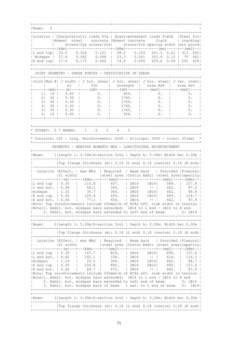
71
+---------+--------------------------+------------------------------+---------+
|Beam: 5 |
+---------+--------------------------+------------------------------+---------+
|Location | Characteristic loads G+Q | Quasi-permanent loads G+ψ2Q |Steel for|
| |Moment steel concrete |Moment concrete Crack | cracking|
| | stress/fyk stress/fck| stress/fck spacing width |min provd|
|---------+-(kNm)--------------------+-(kNm)---------------(mm)-----+--(mm2)--|
|L end top| 33.0 0.324 0.121 | 28.2 0.103 501.5 0.21 | 313 420|
| Midspan | 27.4 0.282 0.048 | 23.3 0.041 322.4 0.12 | 75 461|
|R end top| 17.6 0.172 0.064 | 14.9 0.054 429.6 0.09 | 291 420|
+---------+--------------------------+------------------------------+---------+
+-----------------------------------------------------------------------------+
JOINT GEOMETRY - SHEAR FORCES - VERIFICATION IN SHEAR
+-----+-----+---------+-------------+-------------+-------------+-------------+
|Joint|Max Φ| J width | J hor. shear| J hor. shear| J hor. steel| J ver. steel|
| | | bj | Vjh | strength | area Ash | area Asv |
+-----+-(mm)+---(m)---+----(kN)-----+----(kN)-----+----(mm2)----+----(mm2)----+
| 1| 14 | 0.45 | 0. | 904. | 0. | 0. |
| 2| 30 | 0.30 | 0. | 1740. | 0. | 0. |
| 3| 30 | 0.30 | 0. | 1759. | 0. | 0. |
| 4| 30 | 0.30 | 0. | 1760. | 0. | 0. |
| 5| 30 | 0.30 | 0. | 1740. | 0. | 0. |
| 6| 14 | 0.45 | 0. | 904. | 0. | 0. |
+-----+-----+---------+-------------+-------------+-------------+-------------+
*-----------------------------------------------------------------------------*
* STOREY: 5 * BEAMS: 1 2 3 4 5
*-----------------------------------------------------------------------------*
* Concrete: C25 - Long. Reinforcement: S500 - Stirrups: S500 - Cover: 35(mm) *
*-----------------------------------------------------------------------------*
GEOMETRY - BENDING MOMENTS MEd - LONGITUDINAL REINFORCEMENT
+-----------------------------------------------------------------------------+
|Beam: 1|Length l: 5.50m|X-section InvL | Depth h: 0.50m| Width bw: 0.30m |
|-----------+-----------------------------------------------------------------|
| |Top flange thickness (m): 0.18 (L end) 0.18 (centre) 0.18 (R end)|
|-----------+-----------------------------------------------------------------|
| Location |Effect. | max MEd | Required | Beam bars | Provided |Flexural|
| |fl width| |steel area |Contin Addit |steel area|capacity|
|-----------+--(m)---+--(kNm)---+---(mm2)---+-------------+--(mm2)---+-(kNm)--|
|L end top | 0.30 | 110.8 | 607. | 2Φ14 1Φ14| 589. | 107.8 |
|L end bot. | 0.48 | 58.1 | 344. | 2Φ14 -- | 462. | 87.2 |
|midspan | 1.32 | 30.7 | 344. | 2Φ14 1Φ14| 462. | 88.8 |
|R end top | 0.30 | 125.4 | 693. | 2Φ14 1Φ16| 689. | 124.7 |
|R end bot. | 0.66 | 77.1 | 404. | 2Φ14 -- | 462. | 87.9 |
|Note: Top reinforcements include 250mm2/m of EC8s eff. slab width in tension |
|Note:1. Addit. bot. midspan bars extended: 1Φ14 to L end - 1Φ14 to R end |
| 2. Addit. bot. midspan bars extended to Left end of beam 2: 1Φ14 |
+-----------------------------------------------------------------------------+
+-----------------------------------------------------------------------------+
|Beam: 2|Length l: 5.30m|X-section InvL | Depth h: 0.50m| Width bw: 0.30m |
|-----------+-----------------------------------------------------------------|
| |Top flange thickness (m): 0.18 (L end) 0.18 (centre) 0.18 (R end)|
|-----------+-----------------------------------------------------------------|
| Location |Effect. | max MEd | Required | Beam bars | Provided |Flexural|
| |fl width| |steel area |Contin Addit |steel area|capacity|
|-----------+--(m)---+--(kNm)---+---(mm2)---+-------------+--(mm2)---+-(kNm)--|
|L end top | 0.30 | 147.7 | 829. | 2Φ14 2Φ16| 890. | 157.6 |
|L end bot. | 0.66 | 102.1 | 538. | 2Φ14 -- | 616. | 116.3 |
|midspan | 1.14 | 20.5 | 344. | 2Φ14 1Φ14| 462. | 88.7 |
|R end top | 0.30 | 156.8 | 885. | 2Φ14 2Φ16| 890. | 157.6 |
|R end bot. | 0.66 | 89.7 | 472. | 2Φ14 -- | 462. | 87.9 |
|Note: Top reinforcements include 250mm2/m of EC8s eff. slab width in tension |
|Note:1. Addit. bot. midspan bars extended: 1Φ14 to L end - 1Φ14 to R end |
| 2. Addit. bot. midspan bars extended to Left end of beam 3: 1Φ14 |
| 3. Addit. bot. midspan bars of beam 1 ext. to L end of beam 2: 1Φ14|
+-----------------------------------------------------------------------------+
+-----------------------------------------------------------------------------+
|Beam: 3|Length l: 5.30m|X-section InvL | Depth h: 0.50m| Width bw: 0.30m |
|-----------+-----------------------------------------------------------------|
| |Top flange thickness (m): 0.18 (L end) 0.18 (centre) 0.18 (R end)|
|-----------+-----------------------------------------------------------------|

72
| Location |Effect. | max MEd | Required | Beam bars | Provided |Flexural|
| |fl width| |steel area |Contin Addit |steel area|capacity|
|-----------+--(m)---+--(kNm)---+---(mm2)---+-------------+--(mm2)---+-(kNm)--|
|L end top | 0.30 | 153.5 | 864. | 2Φ14 2Φ16| 890. | 157.6 |
|L end bot. | 0.66 | 95.9 | 505. | 2Φ14 -- | 616. | 116.3 |
|midspan | 1.14 | 20.4 | 344. | 2Φ14 1Φ14| 462. | 88.7 |
|R end top | 0.30 | 153.4 | 864. | 2Φ14 2Φ16| 890. | 157.6 |
|R end bot. | 0.66 | 96.0 | 505. | 2Φ14 -- | 616. | 116.3 |
|Note: Top reinforcements include 250mm2/m of EC8s eff. slab width in tension |
|Note:1. Addit. bot. midspan bars extended: 1Φ14 to L end - 1Φ14 to R end |
| 2. Addit. bot. midspan bars of beam 4 ext. to R end of beam 3: 1Φ14 |
| 3. Addit. bot. midspan bars of beam 2 ext. to L end of beam 3: 1Φ14|
+-----------------------------------------------------------------------------+
+-----------------------------------------------------------------------------+
|Beam: 4|Length l: 5.30m|X-section InvL | Depth h: 0.50m| Width bw: 0.30m |
|-----------+-----------------------------------------------------------------|
| |Top flange thickness (m): 0.18 (L end) 0.18 (centre) 0.18 (R end)|
|-----------+-----------------------------------------------------------------|
| Location |Effect. | max MEd | Required | Beam bars | Provided |Flexural|
| |fl width| |steel area |Contin Addit |steel area|capacity|
|-----------+--(m)---+--(kNm)---+---(mm2)---+-------------+--(mm2)---+-(kNm)--|
|L end top | 0.30 | 156.9 | 886. | 2Φ14 2Φ16| 890. | 157.6 |
|L end bot. | 0.66 | 89.6 | 471. | 2Φ14 -- | 462. | 87.9 |
|midspan | 1.14 | 22.0 | 344. | 2Φ14 1Φ14| 462. | 88.7 |
|R end top | 0.30 | 147.6 | 828. | 2Φ14 2Φ16| 890. | 157.6 |
|R end bot. | 0.66 | 102.2 | 539. | 2Φ14 -- | 616. | 116.3 |
|Note: Top reinforcements include 250mm2/m of EC8s eff. slab width in tension |
|Note:1. Addit. bot. midspan bars extended: 1Φ14 to L end - 1Φ14 to R end |
| 2. Addit. bot. midspan bars extended to Right end of beam 3: 1Φ14|
| 3. Addit. bot. midspan bars of beam 5 ext. to R end of beam 4: 1Φ14 |
+-----------------------------------------------------------------------------+
+-----------------------------------------------------------------------------+
|Beam: 5|Length l: 5.50m|X-section InvL | Depth h: 0.50m| Width bw: 0.30m |
|-----------+-----------------------------------------------------------------|
| |Top flange thickness (m): 0.18 (L end) 0.18 (centre) 0.18 (R end)|
|-----------+-----------------------------------------------------------------|
| Location |Effect. | max MEd | Required | Beam bars | Provided |Flexural|
| |fl width| |steel area |Contin Addit |steel area|capacity|
|-----------+--(m)---+--(kNm)---+---(mm2)---+-------------+--(mm2)---+-(kNm)--|
|L end top | 0.30 | 125.5 | 694. | 2Φ14 1Φ16| 689. | 124.7 |
|L end bot. | 0.66 | 77.0 | 404. | 2Φ14 -- | 462. | 87.9 |
|midspan | 1.32 | 30.7 | 344. | 2Φ14 1Φ14| 462. | 88.8 |
|R end top | 0.30 | 110.7 | 606. | 2Φ14 1Φ14| 589. | 107.8 |
|R end bot. | 0.48 | 58.2 | 344. | 2Φ14 -- | 462. | 87.2 |
|Note: Top reinforcements include 250mm2/m of EC8s eff. slab width in tension |
|Note:1. Addit. bot. midspan bars extended: 1Φ14 to L end - 1Φ14 to R end |
| 2. Addit. bot. midspan bars extended to Right end of beam 4: 1Φ14|
+-----------------------------------------------------------------------------+
+-----------------------------------------------------------------------------+
SLS CHECKS: STRESS LIMITS, CRACK WIDTH CONTROL FOR Wmax=0.3mm & min STEEL AREA
+---------+--------------------------+------------------------------+---------+
|Beam: 1 |
+---------+--------------------------+------------------------------+---------+
|Location | Characteristic loads G+Q | Quasi-permanent loads G+ψ2Q |Steel for|
| |Moment steel concrete |Moment concrete Crack | cracking|
| | stress/fyk stress/fck| stress/fck spacing width |min provd|
|---------+-(kNm)--------------------+-(kNm)---------------(mm)-----+--(mm2)--|
|L end top| 30.9 0.306 0.113 | 26.3 0.096 418.7 0.16 | 301 461|
| Midspan | 23.9 0.247 0.042 | 20.4 0.036 322.4 0.10 | 75 461|
|R end top| 28.3 0.256 0.100 | 24.2 0.086 474.9 0.16 | 339 508|
+---------+--------------------------+------------------------------+---------+
|Beam: 2 |
+---------+--------------------------+------------------------------+---------+
|Location | Characteristic loads G+Q | Quasi-permanent loads G+ψ2Q |Steel for|
| |Moment steel concrete |Moment concrete Crack | cracking|
| | stress/fyk stress/fck| stress/fck spacing width |min provd|
|---------+-(kNm)--------------------+-(kNm)---------------(mm)-----+--(mm2)--|
|L end top| 26.7 0.170 0.080 | 22.8 0.068 385.0 0.08 | 346 709|
| Midspan | 15.9 0.165 0.030 | 13.6 0.026 322.4 0.07 | 75 461|
|R end top| 39.4 0.251 0.124 | 33.6 0.106 381.5 0.12 | 346 709|
+---------+--------------------------+------------------------------+---------+

73
|Beam: 3 |
+---------+--------------------------+------------------------------+---------+
|Location | Characteristic loads G+Q | Quasi-permanent loads G+ψ2Q |Steel for|
| |Moment steel concrete |Moment concrete Crack | cracking|
| | stress/fyk stress/fck| stress/fck spacing width |min provd|
|---------+-(kNm)--------------------+-(kNm)---------------(mm)-----+--(mm2)--|
|L end top| 33.7 0.214 0.101 | 28.8 0.086 385.0 0.11 | 346 709|
| Midspan | 15.8 0.164 0.030 | 13.5 0.026 322.4 0.07 | 75 461|
|R end top| 33.7 0.214 0.101 | 28.7 0.086 385.0 0.11 | 346 709|
+---------+--------------------------+------------------------------+---------+
|Beam: 4 |
+---------+--------------------------+------------------------------+---------+
|Location | Characteristic loads G+Q | Quasi-permanent loads G+ψ2Q |Steel for|
| |Moment steel concrete |Moment concrete Crack | cracking|
| | stress/fyk stress/fck| stress/fck spacing width |min provd|
|---------+-(kNm)--------------------+-(kNm)---------------(mm)-----+--(mm2)--|
|L end top| 39.5 0.252 0.124 | 33.7 0.106 381.5 0.12 | 346 709|
| Midspan | 17.1 0.177 0.033 | 14.5 0.028 322.4 0.07 | 75 461|
|R end top| 26.6 0.169 0.080 | 22.7 0.068 385.0 0.08 | 346 709|
+---------+--------------------------+------------------------------+---------+
|Beam: 5 |
+---------+--------------------------+------------------------------+---------+
|Location | Characteristic loads G+Q | Quasi-permanent loads G+ψ2Q |Steel for|
| |Moment steel concrete |Moment concrete Crack | cracking|
| | stress/fyk stress/fck| stress/fck spacing width |min provd|
|---------+-(kNm)--------------------+-(kNm)---------------(mm)-----+--(mm2)--|
|L end top| 28.3 0.238 0.098 | 24.2 0.084 470.6 0.14 | 339 508|
| Midspan | 23.9 0.246 0.042 | 20.3 0.036 322.4 0.10 | 75 461|
|R end top| 30.9 0.281 0.110 | 26.3 0.093 415.0 0.15 | 301 461|
+---------+--------------------------+------------------------------+---------+
+-----------------------------------------------------------------------------+
JOINT GEOMETRY - SHEAR FORCES - VERIFICATION IN SHEAR
+-----+-----+---------+-------------+-------------+-------------+-------------+
|Joint|Max Φ| J width | J hor. shear| J hor. shear| J hor. steel| J ver. steel|
| | | bj | Vjh | strength | area Ash | area Asv |
+-----+-(mm)+---(m)---+----(kN)-----+----(kN)-----+----(mm2)----+----(mm2)----+
| 1| 14 | 0.45 | 0. | 848. | 0. | 0. |
| 2| 32 | 0.30 | 0. | 1617. | 0. | 0. |
| 3| 32 | 0.30 | 0. | 1658. | 0. | 0. |
| 4| 32 | 0.30 | 0. | 1659. | 0. | 0. |
| 5| 32 | 0.30 | 0. | 1617. | 0. | 0. |
| 6| 14 | 0.45 | 0. | 848. | 0. | 0. |
+-----+-----+---------+-------------+-------------+-------------+-------------+
*-----------------------------------------------------------------------------*
* STOREY: 4 * BEAMS: 1 2 3 4 5
*-----------------------------------------------------------------------------*
* Concrete: C25 - Long. Reinforcement: S500 - Stirrups: S500 - Cover: 35(mm) *
*-----------------------------------------------------------------------------*
GEOMETRY - BENDING MOMENTS MEd - LONGITUDINAL REINFORCEMENT
+-----------------------------------------------------------------------------+
|Beam: 1|Length l: 5.50m|X-section InvL | Depth h: 0.50m| Width bw: 0.30m |
|-----------+-----------------------------------------------------------------|
| |Top flange thickness (m): 0.18 (L end) 0.18 (centre) 0.18 (R end)|
|-----------+-----------------------------------------------------------------|
| Location |Effect. | max MEd | Required | Beam bars | Provided |Flexural|
| |fl width| |steel area |Contin Addit |steel area|capacity|
|-----------+--(m)---+--(kNm)---+---(mm2)---+-------------+--(mm2)---+-(kNm)--|
|L end top | 0.30 | 113.8 | 625. | 2Φ14 2Φ12| 662. | 120.1 |
|L end bot. | 0.48 | 65.5 | 345. | 2Φ14 -- | 462. | 87.2 |
|midspan | 1.32 | 31.0 | 344. | 2Φ14 1Φ14| 462. | 88.8 |
|R end top | 0.30 | 133.2 | 740. | 2Φ14 1Φ18| 742. | 133.6 |
|R end bot. | 0.66 | 82.0 | 430. | 2Φ14 -- | 462. | 87.9 |
|Note: Top reinforcements include 250mm2/m of EC8s eff. slab width in tension |
|Note:1. Addit. bot. midspan bars extended: 1Φ14 to L end - 1Φ14 to R end |
| 2. Addit. bot. midspan bars extended to Left end of beam 2: 1Φ14 |
+-----------------------------------------------------------------------------+
+-----------------------------------------------------------------------------+
|Beam: 2|Length l: 5.30m|X-section InvL | Depth h: 0.50m| Width bw: 0.30m |
|-----------+-----------------------------------------------------------------|
| |Top flange thickness (m): 0.18 (L end) 0.18 (centre) 0.18 (R end)|

74
|-----------+-----------------------------------------------------------------|
| Location |Effect. | max MEd | Required | Beam bars | Provided |Flexural|
| |fl width| |steel area |Contin Addit |steel area|capacity|
|-----------+--(m)---+--(kNm)---+---(mm2)---+-------------+--(mm2)---+-(kNm)--|
|L end top | 0.30 | 156.8 | 885. | 2Φ14 2Φ18| 997. | 174.4 |
|L end bot. | 0.66 | 109.0 | 576. | 2Φ14 -- | 616. | 116.3 |
|midspan | 1.14 | 20.4 | 344. | 2Φ14 1Φ14| 462. | 88.7 |
|R end top | 0.30 | 163.8 | 929. | 2Φ14 2Φ16| 890. | 157.6 |
|R end bot. | 0.66 | 98.3 | 518. | 2Φ14 1Φ20| 776. | 145.5 |
|Note: Top reinforcements include 250mm2/m of EC8s eff. slab width in tension |
|Note:1. Addit. bot. midspan bars extended: 1Φ14 to L end - 1Φ14 to R end |
| 2. Addit. bot. midspan bars extended to Left end of beam 3: 1Φ14 |
| 3. Addit. bot. midspan bars of beam 3 ext. to R end of beam 2: 1Φ14 |
| 4. Addit. bot. midspan bars of beam 1 ext. to L end of beam 2: 1Φ14|
+-----------------------------------------------------------------------------+
+-----------------------------------------------------------------------------+
|Beam: 3|Length l: 5.30m|X-section InvL | Depth h: 0.50m| Width bw: 0.30m |
|-----------+-----------------------------------------------------------------|
| |Top flange thickness (m): 0.18 (L end) 0.18 (centre) 0.18 (R end)|
|-----------+-----------------------------------------------------------------|
| Location |Effect. | max MEd | Required | Beam bars | Provided |Flexural|
| |fl width| |steel area |Contin Addit |steel area|capacity|
|-----------+--(m)---+--(kNm)---+---(mm2)---+-------------+--(mm2)---+-(kNm)--|
|L end top | 0.30 | 160.7 | 910. | 2Φ14 2Φ16| 890. | 157.6 |
|L end bot. | 0.66 | 103.2 | 544. | 2Φ14 1Φ20| 776. | 145.5 |
|midspan | 1.14 | 20.4 | 344. | 2Φ14 1Φ14| 462. | 88.7 |
|R end top | 0.30 | 160.7 | 910. | 2Φ14 2Φ16| 890. | 157.6 |
|R end bot. | 0.66 | 103.2 | 545. | 2Φ14 1Φ20| 776. | 145.5 |
|Note: Top reinforcements include 250mm2/m of EC8s eff. slab width in tension |
|Note:1. Addit. bot. midspan bars extended: 1Φ14 to L end - 1Φ14 to R end |
| 2. Addit. bot. midspan bars extended to Right end of beam 2: 1Φ14|
| 3. Addit. bot. midspan bars extended to Left end of beam 4: 1Φ14 |
| 4. Addit. bot. midspan bars of beam 4 ext. to R end of beam 3: 1Φ14 |
| 5. Addit. bot. midspan bars of beam 2 ext. to L end of beam 3: 1Φ14|
+-----------------------------------------------------------------------------+
+-----------------------------------------------------------------------------+
|Beam: 4|Length l: 5.30m|X-section InvL | Depth h: 0.50m| Width bw: 0.30m |
|-----------+-----------------------------------------------------------------|
| |Top flange thickness (m): 0.18 (L end) 0.18 (centre) 0.18 (R end)|
|-----------+-----------------------------------------------------------------|
| Location |Effect. | max MEd | Required | Beam bars | Provided |Flexural|
| |fl width| |steel area |Contin Addit |steel area|capacity|
|-----------+--(m)---+--(kNm)---+---(mm2)---+-------------+--(mm2)---+-(kNm)--|
|L end top | 0.30 | 163.9 | 930. | 2Φ14 2Φ16| 890. | 157.6 |
|L end bot. | 0.66 | 98.2 | 518. | 2Φ14 1Φ20| 776. | 145.5 |
|midspan | 1.14 | 21.6 | 344. | 2Φ14 1Φ14| 462. | 88.7 |
|R end top | 0.30 | 156.7 | 885. | 2Φ14 2Φ18| 997. | 174.4 |
|R end bot. | 0.66 | 109.1 | 577. | 2Φ14 -- | 616. | 116.3 |
|Note: Top reinforcements include 250mm2/m of EC8s eff. slab width in tension |
|Note:1. Addit. bot. midspan bars extended: 1Φ14 to L end - 1Φ14 to R end |
| 2. Addit. bot. midspan bars extended to Right end of beam 3: 1Φ14|
| 3. Addit. bot. midspan bars of beam 5 ext. to R end of beam 4: 1Φ14 |
| 4. Addit. bot. midspan bars of beam 3 ext. to L end of beam 4: 1Φ14|
+-----------------------------------------------------------------------------+
+-----------------------------------------------------------------------------+
|Beam: 5|Length l: 5.50m|X-section InvL | Depth h: 0.50m| Width bw: 0.30m |
|-----------+-----------------------------------------------------------------|
| |Top flange thickness (m): 0.18 (L end) 0.18 (centre) 0.18 (R end)|
|-----------+-----------------------------------------------------------------|
| Location |Effect. | max MEd | Required | Beam bars | Provided |Flexural|
| |fl width| |steel area |Contin Addit |steel area|capacity|
|-----------+--(m)---+--(kNm)---+---(mm2)---+-------------+--(mm2)---+-(kNm)--|
|L end top | 0.30 | 133.2 | 740. | 2Φ14 1Φ18| 742. | 133.6 |
|L end bot. | 0.66 | 81.9 | 430. | 2Φ14 -- | 462. | 87.9 |
|midspan | 1.32 | 31.0 | 344. | 2Φ14 1Φ14| 462. | 88.8 |
|R end top | 0.30 | 113.8 | 624. | 2Φ14 2Φ12| 662. | 120.1 |
|R end bot. | 0.48 | 65.6 | 345. | 2Φ14 -- | 462. | 87.2 |
|Note: Top reinforcements include 250mm2/m of EC8s eff. slab width in tension |
|Note:1. Addit. bot. midspan bars extended: 1Φ14 to L end - 1Φ14 to R end |
| 2. Addit. bot. midspan bars extended to Right end of beam 4: 1Φ14|
+-----------------------------------------------------------------------------+

75
+-----------------------------------------------------------------------------+
SLS CHECKS: STRESS LIMITS, CRACK WIDTH CONTROL FOR Wmax=0.3mm & min STEEL AREA
+---------+--------------------------+------------------------------+---------+
|Beam: 1 |
+---------+--------------------------+------------------------------+---------+
|Location | Characteristic loads G+Q | Quasi-permanent loads G+ψ2Q |Steel for|
| |Moment steel concrete |Moment concrete Crack | cracking|
| | stress/fyk stress/fck| stress/fck spacing width |min provd|
|---------+-(kNm)--------------------+-(kNm)---------------(mm)-----+--(mm2)--|
|L end top| 28.4 0.247 0.099 | 24.2 0.084 364.1 0.11 | 286 534|
| Midspan | 24.1 0.249 0.042 | 20.5 0.036 322.4 0.10 | 75 461|
|R end top| 30.0 0.249 0.103 | 25.6 0.088 460.2 0.15 | 357 562|
+---------+--------------------------+------------------------------+---------+
|Beam: 2 |
+---------+--------------------------+------------------------------+---------+
|Location | Characteristic loads G+Q | Quasi-permanent loads G+ψ2Q |Steel for|
| |Moment steel concrete |Moment concrete Crack | cracking|
| | stress/fyk stress/fck| stress/fck spacing width |min provd|
|---------+-(kNm)--------------------+-(kNm)---------------(mm)-----+--(mm2)--|
|L end top| 28.0 0.158 0.080 | 23.9 0.069 367.7 0.07 | 369 816|
| Midspan | 15.9 0.164 0.030 | 13.5 0.026 322.4 0.07 | 75 461|
|R end top| 38.4 0.243 0.109 | 32.7 0.093 388.4 0.12 | 346 709|
+---------+--------------------------+------------------------------+---------+
|Beam: 3 |
+---------+--------------------------+------------------------------+---------+
|Location | Characteristic loads G+Q | Quasi-permanent loads G+ψ2Q |Steel for|
| |Moment steel concrete |Moment concrete Crack | cracking|
| | stress/fyk stress/fck| stress/fck spacing width |min provd|
|---------+-(kNm)--------------------+-(kNm)---------------(mm)-----+--(mm2)--|
|L end top| 33.8 0.214 0.096 | 28.8 0.082 388.4 0.11 | 346 709|
| Midspan | 15.8 0.164 0.030 | 13.5 0.026 322.4 0.07 | 75 461|
|R end top| 33.7 0.214 0.096 | 28.7 0.082 388.4 0.11 | 346 709|
+---------+--------------------------+------------------------------+---------+
|Beam: 4 |
+---------+--------------------------+------------------------------+---------+
|Location | Characteristic loads G+Q | Quasi-permanent loads G+ψ2Q |Steel for|
| |Moment steel concrete |Moment concrete Crack | cracking|
| | stress/fyk stress/fck| stress/fck spacing width |min provd|
|---------+-(kNm)--------------------+-(kNm)---------------(mm)-----+--(mm2)--|
|L end top| 38.5 0.244 0.109 | 32.8 0.093 388.4 0.12 | 346 709|
| Midspan | 16.8 0.174 0.032 | 14.3 0.027 322.4 0.07 | 75 461|
|R end top| 27.9 0.157 0.080 | 23.8 0.068 367.7 0.07 | 369 816|
+---------+--------------------------+------------------------------+---------+
|Beam: 5 |
+---------+--------------------------+------------------------------+---------+
|Location | Characteristic loads G+Q | Quasi-permanent loads G+ψ2Q |Steel for|
| |Moment steel concrete |Moment concrete Crack | cracking|
| | stress/fyk stress/fck| stress/fck spacing width |min provd|
|---------+-(kNm)--------------------+-(kNm)---------------(mm)-----+--(mm2)--|
|L end top| 30.0 0.233 0.101 | 25.6 0.086 456.2 0.14 | 357 562|
| Midspan | 24.1 0.249 0.042 | 20.5 0.036 322.4 0.10 | 75 461|
|R end top| 28.3 0.229 0.097 | 24.1 0.082 361.3 0.11 | 286 534|
+---------+--------------------------+------------------------------+---------+
+-----------------------------------------------------------------------------+
JOINT GEOMETRY - SHEAR FORCES - VERIFICATION IN SHEAR
+-----+-----+---------+-------------+-------------+-------------+-------------+
|Joint|Max Φ| J width | J hor. shear| J hor. shear| J hor. steel| J ver. steel|
| | | bj | Vjh | strength | area Ash | area Asv |
+-----+-(mm)+---(m)---+----(kN)-----+----(kN)-----+----(mm2)----+----(mm2)----+
| 1| 14 | 0.45 | 0. | 789. | 0. | 0. |
| 2| 34 | 0.30 | 0. | 1484. | 0. | 0. |
| 3| 32 | 0.30 | 0. | 1551. | 0. | 0. |
| 4| 32 | 0.30 | 0. | 1552. | 0. | 0. |
| 5| 34 | 0.30 | 0. | 1484. | 0. | 0. |
| 6| 14 | 0.45 | 0. | 789. | 0. | 0. |
+-----+-----+---------+-------------+-------------+-------------+-------------+
*-----------------------------------------------------------------------------*
* STOREY: 3 * BEAMS: 1 2 3 4 5
*-----------------------------------------------------------------------------*
* Concrete: C25 - Long. Reinforcement: S500 - Stirrups: S500 - Cover: 35(mm) *

76
*-----------------------------------------------------------------------------*
GEOMETRY - BENDING MOMENTS MEd - LONGITUDINAL REINFORCEMENT
+-----------------------------------------------------------------------------+
|Beam: 1|Length l: 5.50m|X-section InvL | Depth h: 0.50m| Width bw: 0.30m |
|-----------+-----------------------------------------------------------------|
| |Top flange thickness (m): 0.18 (L end) 0.18 (centre) 0.18 (R end)|
|-----------+-----------------------------------------------------------------|
| Location |Effect. | max MEd | Required | Beam bars | Provided |Flexural|
| |fl width| |steel area |Contin Addit |steel area|capacity|
|-----------+--(m)---+--(kNm)---+---(mm2)---+-------------+--(mm2)---+-(kNm)--|
|L end top | 0.30 | 117.0 | 643. | 2Φ14 2Φ12| 662. | 120.1 |
|L end bot. | 0.48 | 70.8 | 373. | 2Φ14 -- | 462. | 87.2 |
|midspan | 1.32 | 30.5 | 344. | 2Φ14 1Φ14| 462. | 88.8 |
|R end top | 0.30 | 140.0 | 781. | 2Φ14 1Φ20| 802. | 143.4 |
|R end bot. | 0.66 | 85.6 | 450. | 2Φ14 -- | 462. | 87.9 |
|Note: Top reinforcements include 250mm2/m of EC8s eff. slab width in tension |
|Note:1. Addit. bot. midspan bars extended: 1Φ14 to L end - 1Φ14 to R end |
| 2. Addit. bot. midspan bars extended to Left end of beam 2: 1Φ14 |
+-----------------------------------------------------------------------------+
+-----------------------------------------------------------------------------+
|Beam: 2|Length l: 5.30m|X-section InvL | Depth h: 0.50m| Width bw: 0.30m |
|-----------+-----------------------------------------------------------------|
| |Top flange thickness (m): 0.18 (L end) 0.18 (centre) 0.18 (R end)|
|-----------+-----------------------------------------------------------------|
| Location |Effect. | max MEd | Required | Beam bars | Provided |Flexural|
| |fl width| |steel area |Contin Addit |steel area|capacity|
|-----------+--(m)---+--(kNm)---+---(mm2)---+-------------+--(mm2)---+-(kNm)--|
|L end top | 0.30 | 164.6 | 934. | 2Φ14 2Φ20| 1116. | 192.7 |
|L end bot. | 0.66 | 115.3 | 610. | 2Φ14 -- | 616. | 116.3 |
|midspan | 1.14 | 20.4 | 344. | 2Φ14 1Φ14| 462. | 88.7 |
|R end top | 0.30 | 170.0 | 969. | 2Φ14 3Φ14| 950. | 167.0 |
|R end bot. | 0.66 | 105.9 | 559. | 2Φ14 1Φ20| 776. | 145.5 |
|Note: Top reinforcements include 250mm2/m of EC8s eff. slab width in tension |
|Note:1. Addit. bot. midspan bars extended: 1Φ14 to L end - 1Φ14 to R end |
| 2. Addit. bot. midspan bars extended to Left end of beam 3: 1Φ14 |
| 3. Addit. bot. midspan bars of beam 3 ext. to R end of beam 2: 1Φ14 |
| 4. Addit. bot. midspan bars of beam 1 ext. to L end of beam 2: 1Φ14|
+-----------------------------------------------------------------------------+
+-----------------------------------------------------------------------------+
|Beam: 3|Length l: 5.30m|X-section InvL | Depth h: 0.50m| Width bw: 0.30m |
|-----------+-----------------------------------------------------------------|
| |Top flange thickness (m): 0.18 (L end) 0.18 (centre) 0.18 (R end)|
|-----------+-----------------------------------------------------------------|
| Location |Effect. | max MEd | Required | Beam bars | Provided |Flexural|
| |fl width| |steel area |Contin Addit |steel area|capacity|
|-----------+--(m)---+--(kNm)---+---(mm2)---+-------------+--(mm2)---+-(kNm)--|
|L end top | 0.30 | 167.1 | 950. | 2Φ14 3Φ14| 950. | 167.0 |
|L end bot. | 0.66 | 109.7 | 580. | 2Φ14 1Φ20| 776. | 145.5 |
|midspan | 1.14 | 20.4 | 344. | 2Φ14 1Φ14| 462. | 88.7 |
|R end top | 0.30 | 167.1 | 950. | 2Φ14 3Φ14| 950. | 167.0 |
|R end bot. | 0.66 | 109.7 | 580. | 2Φ14 1Φ20| 776. | 145.5 |
|Note: Top reinforcements include 250mm2/m of EC8s eff. slab width in tension |
|Note:1. Addit. bot. midspan bars extended: 1Φ14 to L end - 1Φ14 to R end |
| 2. Addit. bot. midspan bars extended to Right end of beam 2: 1Φ14|
| 3. Addit. bot. midspan bars extended to Left end of beam 4: 1Φ14 |
| 4. Addit. bot. midspan bars of beam 4 ext. to R end of beam 3: 1Φ14 |
| 5. Addit. bot. midspan bars of beam 2 ext. to L end of beam 3: 1Φ14|
+-----------------------------------------------------------------------------+
+-----------------------------------------------------------------------------+
|Beam: 4|Length l: 5.30m|X-section InvL | Depth h: 0.50m| Width bw: 0.30m |
|-----------+-----------------------------------------------------------------|
| |Top flange thickness (m): 0.18 (L end) 0.18 (centre) 0.18 (R end)|
|-----------+-----------------------------------------------------------------|
| Location |Effect. | max MEd | Required | Beam bars | Provided |Flexural|
| |fl width| |steel area |Contin Addit |steel area|capacity|
|-----------+--(m)---+--(kNm)---+---(mm2)---+-------------+--(mm2)---+-(kNm)--|
|L end top | 0.30 | 170.1 | 969. | 2Φ14 3Φ14| 950. | 167.0 |
|L end bot. | 0.66 | 105.8 | 559. | 2Φ14 1Φ20| 776. | 145.5 |
|midspan | 1.14 | 21.5 | 344. | 2Φ14 1Φ14| 462. | 88.7 |
|R end top | 0.30 | 164.5 | 934. | 2Φ14 2Φ20| 1116. | 192.7 |
|R end bot. | 0.66 | 115.3 | 610. | 2Φ14 -- | 616. | 116.3 |

77
|Note: Top reinforcements include 250mm2/m of EC8s eff. slab width in tension |
|Note:1. Addit. bot. midspan bars extended: 1Φ14 to L end - 1Φ14 to R end |
| 2. Addit. bot. midspan bars extended to Right end of beam 3: 1Φ14|
| 3. Addit. bot. midspan bars of beam 5 ext. to R end of beam 4: 1Φ14 |
| 4. Addit. bot. midspan bars of beam 3 ext. to L end of beam 4: 1Φ14|
+-----------------------------------------------------------------------------+
+-----------------------------------------------------------------------------+
|Beam: 5|Length l: 5.50m|X-section InvL | Depth h: 0.50m| Width bw: 0.30m |
|-----------+-----------------------------------------------------------------|
| |Top flange thickness (m): 0.18 (L end) 0.18 (centre) 0.18 (R end)|
|-----------+-----------------------------------------------------------------|
| Location |Effect. | max MEd | Required | Beam bars | Provided |Flexural|
| |fl width| |steel area |Contin Addit |steel area|capacity|
|-----------+--(m)---+--(kNm)---+---(mm2)---+-------------+--(mm2)---+-(kNm)--|
|L end top | 0.30 | 140.0 | 782. | 2Φ14 1Φ20| 802. | 143.4 |
|L end bot. | 0.66 | 85.6 | 450. | 2Φ14 -- | 462. | 87.9 |
|midspan | 1.32 | 30.4 | 344. | 2Φ14 1Φ14| 462. | 88.8 |
|R end top | 0.30 | 116.9 | 643. | 2Φ14 2Φ12| 662. | 120.1 |
|R end bot. | 0.48 | 70.8 | 373. | 2Φ14 -- | 462. | 87.2 |
|Note: Top reinforcements include 250mm2/m of EC8s eff. slab width in tension |
|Note:1. Addit. bot. midspan bars extended: 1Φ14 to L end - 1Φ14 to R end |
| 2. Addit. bot. midspan bars extended to Right end of beam 4: 1Φ14|
+-----------------------------------------------------------------------------+
+-----------------------------------------------------------------------------+
SLS CHECKS: STRESS LIMITS, CRACK WIDTH CONTROL FOR Wmax=0.3mm & min STEEL AREA
+---------+--------------------------+------------------------------+---------+
|Beam: 1 |
+---------+--------------------------+------------------------------+---------+
|Location | Characteristic loads G+Q | Quasi-permanent loads G+ψ2Q |Steel for|
| |Moment steel concrete |Moment concrete Crack | cracking|
| | stress/fyk stress/fck| stress/fck spacing width |min provd|
|---------+-(kNm)--------------------+-(kNm)---------------(mm)-----+--(mm2)--|
|L end top| 27.2 0.236 0.095 | 23.1 0.081 364.1 0.11 | 286 534|
| Midspan | 23.7 0.244 0.042 | 20.2 0.036 322.4 0.10 | 75 461|
|R end top| 31.8 0.241 0.106 | 27.2 0.091 446.0 0.14 | 372 622|
+---------+--------------------------+------------------------------+---------+
|Beam: 2 |
+---------+--------------------------+------------------------------+---------+
|Location | Characteristic loads G+Q | Quasi-permanent loads G+ψ2Q |Steel for|
| |Moment steel concrete |Moment concrete Crack | cracking|
| | stress/fyk stress/fck| stress/fck spacing width |min provd|
|---------+-(kNm)--------------------+-(kNm)---------------(mm)-----+--(mm2)--|
|L end top| 28.9 0.145 0.080 | 24.7 0.068 351.8 0.07 | 385 936|
| Midspan | 15.9 0.165 0.030 | 13.5 0.026 322.4 0.07 | 75 461|
|R end top| 37.6 0.222 0.104 | 32.1 0.089 352.7 0.10 | 325 769|
+---------+--------------------------+------------------------------+---------+
|Beam: 3 |
+---------+--------------------------+------------------------------+---------+
|Location | Characteristic loads G+Q | Quasi-permanent loads G+ψ2Q |Steel for|
| |Moment steel concrete |Moment concrete Crack | cracking|
| | stress/fyk stress/fck| stress/fck spacing width |min provd|
|---------+-(kNm)--------------------+-(kNm)---------------(mm)-----+--(mm2)--|
|L end top| 33.7 0.199 0.094 | 28.7 0.080 352.7 0.09 | 325 769|
| Midspan | 15.9 0.165 0.030 | 13.5 0.026 322.4 0.07 | 75 461|
|R end top| 33.6 0.199 0.093 | 28.7 0.080 352.7 0.09 | 325 769|
+---------+--------------------------+------------------------------+---------+
|Beam: 4 |
+---------+--------------------------+------------------------------+---------+
|Location | Characteristic loads G+Q | Quasi-permanent loads G+ψ2Q |Steel for|
| |Moment steel concrete |Moment concrete Crack | cracking|
| | stress/fyk stress/fck| stress/fck spacing width |min provd|
|---------+-(kNm)--------------------+-(kNm)---------------(mm)-----+--(mm2)--|
|L end top| 37.7 0.223 0.105 | 32.1 0.089 352.7 0.10 | 325 769|
| Midspan | 16.7 0.173 0.032 | 14.2 0.027 322.4 0.07 | 75 461|
|R end top| 28.8 0.144 0.080 | 24.6 0.068 351.8 0.06 | 385 936|
+---------+--------------------------+------------------------------+---------+
|Beam: 5 |
+---------+--------------------------+------------------------------+---------+
|Location | Characteristic loads G+Q | Quasi-permanent loads G+ψ2Q |Steel for|
| |Moment steel concrete |Moment concrete Crack | cracking|
| | stress/fyk stress/fck| stress/fck spacing width |min provd|

78
|---------+-(kNm)--------------------+-(kNm)---------------(mm)-----+--(mm2)--|
|L end top| 31.8 0.227 0.104 | 27.2 0.089 442.4 0.13 | 372 622|
| Midspan | 23.7 0.244 0.042 | 20.2 0.036 322.4 0.10 | 75 461|
|R end top| 27.1 0.219 0.092 | 23.1 0.079 361.3 0.10 | 286 534|
+---------+--------------------------+------------------------------+---------+
+-----------------------------------------------------------------------------+
JOINT GEOMETRY - SHEAR FORCES - VERIFICATION IN SHEAR
+-----+-----+---------+-------------+-------------+-------------+-------------+
|Joint|Max Φ| J width | J hor. shear| J hor. shear| J hor. steel| J ver. steel|
| | | bj | Vjh | strength | area Ash | area Asv |
+-----+-(mm)+---(m)---+----(kN)-----+----(kN)-----+----(mm2)----+----(mm2)----+
| 1| 14 | 0.45 | 0. | 724. | 0. | 0. |
| 2| 34 | 0.30 | 0. | 1338. | 0. | 0. |
| 3| 34 | 0.30 | 0. | 1437. | 0. | 0. |
| 4| 34 | 0.30 | 0. | 1437. | 0. | 0. |
| 5| 34 | 0.30 | 0. | 1338. | 0. | 0. |
| 6| 14 | 0.45 | 0. | 724. | 0. | 0. |
+-----+-----+---------+-------------+-------------+-------------+-------------+
*-----------------------------------------------------------------------------*
* STOREY: 2 * BEAMS: 1 2 3 4 5
*-----------------------------------------------------------------------------*
* Concrete: C25 - Long. Reinforcement: S500 - Stirrups: S500 - Cover: 35(mm) *
*-----------------------------------------------------------------------------*
GEOMETRY - BENDING MOMENTS MEd - LONGITUDINAL REINFORCEMENT
+-----------------------------------------------------------------------------+
|Beam: 1|Length l: 5.50m|X-section InvL | Depth h: 0.50m| Width bw: 0.30m |
|-----------+-----------------------------------------------------------------|
| |Top flange thickness (m): 0.18 (L end) 0.18 (centre) 0.18 (R end)|
|-----------+-----------------------------------------------------------------|
| Location |Effect. | max MEd | Required | Beam bars | Provided |Flexural|
| |fl width| |steel area |Contin Addit |steel area|capacity|
|-----------+--(m)---+--(kNm)---+---(mm2)---+-------------+--(mm2)---+-(kNm)--|
|L end top | 0.30 | 114.6 | 630. | 2Φ14 2Φ12| 662. | 120.1 |
|L end bot. | 0.48 | 70.8 | 373. | 2Φ14 -- | 462. | 87.2 |
|midspan | 1.32 | 29.6 | 344. | 2Φ14 1Φ14| 462. | 88.8 |
|R end top | 0.30 | 140.0 | 782. | 2Φ14 1Φ20| 802. | 143.4 |
|R end bot. | 0.66 | 81.6 | 428. | 2Φ14 -- | 462. | 87.9 |
|Note: Top reinforcements include 250mm2/m of EC8s eff. slab width in tension |
|Note:1. Addit. bot. midspan bars extended: 1Φ14 to L end - 1Φ14 to R end |
| 2. Addit. bot. midspan bars extended to Left end of beam 2: 1Φ14 |
+-----------------------------------------------------------------------------+
+-----------------------------------------------------------------------------+
|Beam: 2|Length l: 5.30m|X-section InvL | Depth h: 0.50m| Width bw: 0.30m |
|-----------+-----------------------------------------------------------------|
| |Top flange thickness (m): 0.18 (L end) 0.18 (centre) 0.18 (R end)|
|-----------+-----------------------------------------------------------------|
| Location |Effect. | max MEd | Required | Beam bars | Provided |Flexural|
| |fl width| |steel area |Contin Addit |steel area|capacity|
|-----------+--(m)---+--(kNm)---+---(mm2)---+-------------+--(mm2)---+-(kNm)--|
|L end top | 0.30 | 163.1 | 924. | 2Φ14 2Φ20| 1116. | 192.7 |
|L end bot. | 0.66 | 111.7 | 591. | 2Φ14 -- | 616. | 116.3 |
|midspan | 1.14 | 20.5 | 344. | 2Φ14 1Φ14| 462. | 88.7 |
|R end top | 0.30 | 166.8 | 948. | 2Φ14 2Φ16| 890. | 157.6 |
|R end bot. | 0.66 | 104.5 | 552. | 2Φ14 1Φ20| 776. | 145.5 |
|Note: Top reinforcements include 250mm2/m of EC8s eff. slab width in tension |
|Note:1. Addit. bot. midspan bars extended: 1Φ14 to L end - 1Φ14 to R end |
| 2. Addit. bot. midspan bars extended to Left end of beam 3: 1Φ14 |
| 3. Addit. bot. midspan bars of beam 3 ext. to R end of beam 2: 1Φ14 |
| 4. Addit. bot. midspan bars of beam 1 ext. to L end of beam 2: 1Φ14|
+-----------------------------------------------------------------------------+
+-----------------------------------------------------------------------------+
|Beam: 3|Length l: 5.30m|X-section InvL | Depth h: 0.50m| Width bw: 0.30m |
|-----------+-----------------------------------------------------------------|
| |Top flange thickness (m): 0.18 (L end) 0.18 (centre) 0.18 (R end)|
|-----------+-----------------------------------------------------------------|
| Location |Effect. | max MEd | Required | Beam bars | Provided |Flexural|
| |fl width| |steel area |Contin Addit |steel area|capacity|
|-----------+--(m)---+--(kNm)---+---(mm2)---+-------------+--(mm2)---+-(kNm)--|
|L end top | 0.30 | 164.5 | 933. | 2Φ14 2Φ16| 890. | 157.6 |
|L end bot. | 0.66 | 107.2 | 566. | 2Φ14 1Φ20| 776. | 145.5 |
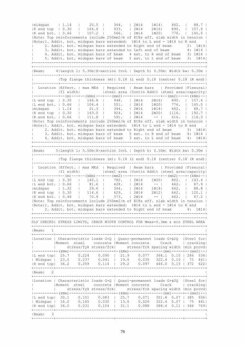
79
|midspan | 1.14 | 20.5 | 344. | 2Φ14 1Φ14| 462. | 88.7 |
|R end top | 0.30 | 164.4 | 933. | 2Φ14 2Φ16| 890. | 157.6 |
|R end bot. | 0.66 | 107.2 | 566. | 2Φ14 1Φ20| 776. | 145.5 |
|Note: Top reinforcements include 250mm2/m of EC8s eff. slab width in tension |
|Note:1. Addit. bot. midspan bars extended: 1Φ14 to L end - 1Φ14 to R end |
| 2. Addit. bot. midspan bars extended to Right end of beam 2: 1Φ14|
| 3. Addit. bot. midspan bars extended to Left end of beam 4: 1Φ14 |
| 4. Addit. bot. midspan bars of beam 4 ext. to R end of beam 3: 1Φ14 |
| 5. Addit. bot. midspan bars of beam 2 ext. to L end of beam 3: 1Φ14|
+-----------------------------------------------------------------------------+
+-----------------------------------------------------------------------------+
|Beam: 4|Length l: 5.30m|X-section InvL | Depth h: 0.50m| Width bw: 0.30m |
|-----------+-----------------------------------------------------------------|
| |Top flange thickness (m): 0.18 (L end) 0.18 (centre) 0.18 (R end)|
|-----------+-----------------------------------------------------------------|
| Location |Effect. | max MEd | Required | Beam bars | Provided |Flexural|
| |fl width| |steel area |Contin Addit |steel area|capacity|
|-----------+--(m)---+--(kNm)---+---(mm2)---+-------------+--(mm2)---+-(kNm)--|
|L end top | 0.30 | 166.8 | 948. | 2Φ14 2Φ16| 890. | 157.6 |
|L end bot. | 0.66 | 104.4 | 551. | 2Φ14 1Φ20| 776. | 145.5 |
|midspan | 1.14 | 21.3 | 344. | 2Φ14 1Φ14| 462. | 88.7 |
|R end top | 0.30 | 163.0 | 924. | 2Φ14 2Φ20| 1116. | 192.7 |
|R end bot. | 0.66 | 111.8 | 591. | 2Φ14 -- | 616. | 116.3 |
|Note: Top reinforcements include 250mm2/m of EC8s eff. slab width in tension |
|Note:1. Addit. bot. midspan bars extended: 1Φ14 to L end - 1Φ14 to R end |
| 2. Addit. bot. midspan bars extended to Right end of beam 3: 1Φ14|
| 3. Addit. bot. midspan bars of beam 5 ext. to R end of beam 4: 1Φ14 |
| 4. Addit. bot. midspan bars of beam 3 ext. to L end of beam 4: 1Φ14|
+-----------------------------------------------------------------------------+
+-----------------------------------------------------------------------------+
|Beam: 5|Length l: 5.50m|X-section InvL | Depth h: 0.50m| Width bw: 0.30m |
|-----------+-----------------------------------------------------------------|
| |Top flange thickness (m): 0.18 (L end) 0.18 (centre) 0.18 (R end)|
|-----------+-----------------------------------------------------------------|
| Location |Effect. | max MEd | Required | Beam bars | Provided |Flexural|
| |fl width| |steel area |Contin Addit |steel area|capacity|
|-----------+--(m)---+--(kNm)---+---(mm2)---+-------------+--(mm2)---+-(kNm)--|
|L end top | 0.30 | 140.1 | 782. | 2Φ14 1Φ20| 802. | 143.4 |
|L end bot. | 0.66 | 81.6 | 428. | 2Φ14 -- | 462. | 87.9 |
|midspan | 1.32 | 29.6 | 344. | 2Φ14 1Φ14| 462. | 88.8 |
|R end top | 0.30 | 114.6 | 629. | 2Φ14 2Φ12| 662. | 120.1 |
|R end bot. | 0.48 | 70.9 | 373. | 2Φ14 -- | 462. | 87.2 |
|Note: Top reinforcements include 250mm2/m of EC8s eff. slab width in tension |
|Note:1. Addit. bot. midspan bars extended: 1Φ14 to L end - 1Φ14 to R end |
| 2. Addit. bot. midspan bars extended to Right end of beam 4: 1Φ14|
+-----------------------------------------------------------------------------+
+-----------------------------------------------------------------------------+
SLS CHECKS: STRESS LIMITS, CRACK WIDTH CONTROL FOR Wmax=0.3mm & min STEEL AREA
+---------+--------------------------+------------------------------+---------+
|Beam: 1 |
+---------+--------------------------+------------------------------+---------+
|Location | Characteristic loads G+Q | Quasi-permanent loads G+ψ2Q |Steel for|
| |Moment steel concrete |Moment concrete Crack | cracking|
| | stress/fyk stress/fck| stress/fck spacing width |min provd|
|---------+-(kNm)--------------------+-(kNm)---------------(mm)-----+--(mm2)--|
|L end top| 25.7 0.224 0.090 | 21.9 0.077 364.1 0.10 | 286 534|
| Midspan | 23.0 0.237 0.041 | 19.6 0.035 322.4 0.10 | 75 461|
|R end top| 34.2 0.259 0.114 | 29.2 0.097 446.0 0.15 | 372 622|
+---------+--------------------------+------------------------------+---------+
|Beam: 2 |
+---------+--------------------------+------------------------------+---------+
|Location | Characteristic loads G+Q | Quasi-permanent loads G+ψ2Q |Steel for|
| |Moment steel concrete |Moment concrete Crack | cracking|
| | stress/fyk stress/fck| stress/fck spacing width |min provd|
|---------+-(kNm)--------------------+-(kNm)---------------(mm)-----+--(mm2)--|
|L end top| 30.1 0.151 0.083 | 25.7 0.071 351.8 0.07 | 385 936|
| Midspan | 16.0 0.165 0.030 | 13.6 0.026 322.4 0.07 | 75 461|
|R end top| 36.5 0.231 0.104 | 31.1 0.088 388.4 0.11 | 346 709|
+---------+--------------------------+------------------------------+---------+
|Beam: 3 |
+---------+--------------------------+------------------------------+---------+

80
|Location | Characteristic loads G+Q | Quasi-permanent loads G+ψ2Q |Steel for|
| |Moment steel concrete |Moment concrete Crack | cracking|
| | stress/fyk stress/fck| stress/fck spacing width |min provd|
|---------+-(kNm)--------------------+-(kNm)---------------(mm)-----+--(mm2)--|
|L end top| 33.6 0.213 0.095 | 28.6 0.081 388.4 0.11 | 346 709|
| Midspan | 16.0 0.165 0.030 | 13.6 0.026 322.4 0.07 | 75 461|
|R end top| 33.6 0.213 0.095 | 28.6 0.081 388.4 0.11 | 346 709|
+---------+--------------------------+------------------------------+---------+
|Beam: 4 |
+---------+--------------------------+------------------------------+---------+
|Location | Characteristic loads G+Q | Quasi-permanent loads G+ψ2Q |Steel for|
| |Moment steel concrete |Moment concrete Crack | cracking|
| | stress/fyk stress/fck| stress/fck spacing width |min provd|
|---------+-(kNm)--------------------+-(kNm)---------------(mm)-----+--(mm2)--|
|L end top| 36.6 0.232 0.104 | 31.2 0.089 388.4 0.12 | 346 709|
| Midspan | 16.5 0.171 0.032 | 14.1 0.027 322.4 0.07 | 75 461|
|R end top| 30.0 0.150 0.083 | 25.6 0.071 351.8 0.07 | 385 936|
+---------+--------------------------+------------------------------+---------+
|Beam: 5 |
+---------+--------------------------+------------------------------+---------+
|Location | Characteristic loads G+Q | Quasi-permanent loads G+ψ2Q |Steel for|
| |Moment steel concrete |Moment concrete Crack | cracking|
| | stress/fyk stress/fck| stress/fck spacing width |min provd|
|---------+-(kNm)--------------------+-(kNm)---------------(mm)-----+--(mm2)--|
|L end top| 34.2 0.244 0.112 | 29.2 0.095 442.4 0.14 | 372 622|
| Midspan | 23.0 0.237 0.041 | 19.6 0.035 322.4 0.10 | 75 461|
|R end top| 25.7 0.208 0.088 | 21.9 0.075 361.3 0.10 | 286 534|
+---------+--------------------------+------------------------------+---------+
+-----------------------------------------------------------------------------+
JOINT GEOMETRY - SHEAR FORCES - VERIFICATION IN SHEAR
+-----+-----+---------+-------------+-------------+-------------+-------------+
|Joint|Max Φ| J width | J hor. shear| J hor. shear| J hor. steel| J ver. steel|
| | | bj | Vjh | strength | area Ash | area Asv |
+-----+-(mm)+---(m)---+----(kN)-----+----(kN)-----+----(mm2)----+----(mm2)----+
| 1| 14 | 0.45 | 0. | 657. | 0. | 0. |
| 2| 36 | 0.30 | 0. | 1176. | 0. | 0. |
| 3| 34 | 0.30 | 0. | 1315. | 0. | 0. |
| 4| 34 | 0.30 | 0. | 1315. | 0. | 0. |
| 5| 36 | 0.30 | 0. | 1176. | 0. | 0. |
| 6| 14 | 0.45 | 0. | 657. | 0. | 0. |
+-----+-----+---------+-------------+-------------+-------------+-------------+
*-----------------------------------------------------------------------------*
* STOREY: 1 * BEAMS: 1 2 3 4 5
*-----------------------------------------------------------------------------*
* Concrete: C25 - Long. Reinforcement: S500 - Stirrups: S500 - Cover: 35(mm) *
*-----------------------------------------------------------------------------*
GEOMETRY - BENDING MOMENTS MEd - LONGITUDINAL REINFORCEMENT
+-----------------------------------------------------------------------------+
|Beam: 1|Length l: 5.50m|X-section InvL | Depth h: 0.50m| Width bw: 0.30m |
|-----------+-----------------------------------------------------------------|
| |Top flange thickness (m): 0.18 (L end) 0.18 (centre) 0.18 (R end)|
|-----------+-----------------------------------------------------------------|
| Location |Effect. | max MEd | Required | Beam bars | Provided |Flexural|
| |fl width| |steel area |Contin Addit |steel area|capacity|
|-----------+--(m)---+--(kNm)---+---(mm2)---+-------------+--(mm2)---+-(kNm)--|
|L end top | 0.30 | 94.5 | 512. | 2Φ14 1Φ12| 548. | 100.7 |
|L end bot. | 0.48 | 61.4 | 344. | 2Φ14 -- | 462. | 87.2 |
|midspan | 1.32 | 30.1 | 344. | 2Φ14 1Φ14| 462. | 88.8 |
|R end top | 0.30 | 130.9 | 726. | 2Φ14 1Φ18| 742. | 133.6 |
|R end bot. | 0.66 | 64.7 | 363. | 2Φ14 -- | 462. | 87.9 |
|Note: Top reinforcements include 250mm2/m of EC8s eff. slab width in tension |
|Note:1. Addit. bot. midspan bars extended: 1Φ14 to L end - 1Φ14 to R end |
| 2. Addit. bot. midspan bars extended to Left end of beam 2: 1Φ14 |
+-----------------------------------------------------------------------------+
+-----------------------------------------------------------------------------+
|Beam: 2|Length l: 5.30m|X-section InvL | Depth h: 0.50m| Width bw: 0.30m |
|-----------+-----------------------------------------------------------------|
| |Top flange thickness (m): 0.18 (L end) 0.18 (centre) 0.18 (R end)|
|-----------+-----------------------------------------------------------------|
| Location |Effect. | max MEd | Required | Beam bars | Provided |Flexural|

81
| |fl width| |steel area |Contin Addit |steel area|capacity|
|-----------+--(m)---+--(kNm)---+---(mm2)---+-------------+--(mm2)---+-(kNm)--|
|L end top | 0.30 | 152.9 | 861. | 2Φ14 2Φ18| 997. | 174.4 |
|L end bot. | 0.66 | 97.2 | 512. | 2Φ14 -- | 616. | 116.3 |
|midspan | 1.14 | 20.4 | 344. | 2Φ14 1Φ14| 462. | 88.7 |
|R end top | 0.30 | 152.2 | 856. | 2Φ14 3Φ12| 827. | 147.5 |
|R end bot. | 0.66 | 93.1 | 490. | 2Φ14 -- | 616. | 116.3 |
|Note: Top reinforcements include 250mm2/m of EC8s eff. slab width in tension |
|Note:1. Addit. bot. midspan bars extended: 1Φ14 to L end - 1Φ14 to R end |
| 2. Addit. bot. midspan bars of beam 3 ext. to R end of beam 2: 1Φ14 |
| 3. Addit. bot. midspan bars of beam 1 ext. to L end of beam 2: 1Φ14|
+-----------------------------------------------------------------------------+
+-----------------------------------------------------------------------------+
|Beam: 3|Length l: 5.30m|X-section InvL | Depth h: 0.50m| Width bw: 0.30m |
|-----------+-----------------------------------------------------------------|
| |Top flange thickness (m): 0.18 (L end) 0.18 (centre) 0.18 (R end)|
|-----------+-----------------------------------------------------------------|
| Location |Effect. | max MEd | Required | Beam bars | Provided |Flexural|
| |fl width| |steel area |Contin Addit |steel area|capacity|
|-----------+--(m)---+--(kNm)---+---(mm2)---+-------------+--(mm2)---+-(kNm)--|
|L end top | 0.30 | 150.0 | 843. | 2Φ14 3Φ12| 827. | 147.5 |
|L end bot. | 0.66 | 93.0 | 489. | 2Φ14 -- | 462. | 87.9 |
|midspan | 1.14 | 20.7 | 344. | 2Φ14 1Φ14| 462. | 88.7 |
|R end top | 0.30 | 150.0 | 843. | 2Φ14 3Φ12| 827. | 147.5 |
|R end bot. | 0.66 | 93.0 | 489. | 2Φ14 -- | 462. | 87.9 |
|Note: Top reinforcements include 250mm2/m of EC8s eff. slab width in tension |
|Note:1. Addit. bot. midspan bars extended: 1Φ14 to L end - 1Φ14 to R end |
| 2. Addit. bot. midspan bars extended to Right end of beam 2: 1Φ14|
| 3. Addit. bot. midspan bars extended to Left end of beam 4: 1Φ14 |
+-----------------------------------------------------------------------------+
+-----------------------------------------------------------------------------+
|Beam: 4|Length l: 5.30m|X-section InvL | Depth h: 0.50m| Width bw: 0.30m |
|-----------+-----------------------------------------------------------------|
| |Top flange thickness (m): 0.18 (L end) 0.18 (centre) 0.18 (R end)|
|-----------+-----------------------------------------------------------------|
| Location |Effect. | max MEd | Required | Beam bars | Provided |Flexural|
| |fl width| |steel area |Contin Addit |steel area|capacity|
|-----------+--(m)---+--(kNm)---+---(mm2)---+-------------+--(mm2)---+-(kNm)--|
|L end top | 0.30 | 152.2 | 857. | 2Φ14 3Φ12| 827. | 147.5 |
|L end bot. | 0.66 | 93.1 | 490. | 2Φ14 -- | 616. | 116.3 |
|midspan | 1.14 | 20.6 | 344. | 2Φ14 1Φ14| 462. | 88.7 |
|R end top | 0.30 | 152.8 | 860. | 2Φ14 2Φ18| 997. | 174.4 |
|R end bot. | 0.66 | 97.3 | 512. | 2Φ14 -- | 616. | 116.3 |
|Note: Top reinforcements include 250mm2/m of EC8s eff. slab width in tension |
|Note:1. Addit. bot. midspan bars extended: 1Φ14 to L end - 1Φ14 to R end |
| 2. Addit. bot. midspan bars of beam 5 ext. to R end of beam 4: 1Φ14 |
| 3. Addit. bot. midspan bars of beam 3 ext. to L end of beam 4: 1Φ14|
+-----------------------------------------------------------------------------+
+-----------------------------------------------------------------------------+
|Beam: 5|Length l: 5.50m|X-section InvL | Depth h: 0.50m| Width bw: 0.30m |
|-----------+-----------------------------------------------------------------|
| |Top flange thickness (m): 0.18 (L end) 0.18 (centre) 0.18 (R end)|
|-----------+-----------------------------------------------------------------|
| Location |Effect. | max MEd | Required | Beam bars | Provided |Flexural|
| |fl width| |steel area |Contin Addit |steel area|capacity|
|-----------+--(m)---+--(kNm)---+---(mm2)---+-------------+--(mm2)---+-(kNm)--|
|L end top | 0.30 | 130.9 | 726. | 2Φ14 1Φ18| 742. | 133.6 |
|L end bot. | 0.66 | 64.7 | 363. | 2Φ14 -- | 462. | 87.9 |
|midspan | 1.32 | 30.1 | 344. | 2Φ14 1Φ14| 462. | 88.8 |
|R end top | 0.30 | 94.5 | 512. | 2Φ14 1Φ12| 548. | 100.7 |
|R end bot. | 0.48 | 61.4 | 344. | 2Φ14 -- | 462. | 87.2 |
|Note: Top reinforcements include 250mm2/m of EC8s eff. slab width in tension |
|Note:1. Addit. bot. midspan bars extended: 1Φ14 to L end - 1Φ14 to R end |
| 2. Addit. bot. midspan bars extended to Right end of beam 4: 1Φ14|
+-----------------------------------------------------------------------------+
+-----------------------------------------------------------------------------+
SLS CHECKS: STRESS LIMITS, CRACK WIDTH CONTROL FOR Wmax=0.3mm & min STEEL AREA
+---------+--------------------------+------------------------------+---------+
|Beam: 1 |
+---------+--------------------------+------------------------------+---------+
|Location | Characteristic loads G+Q | Quasi-permanent loads G+ψ2Q |Steel for|

82
| |Moment steel concrete |Moment concrete Crack | cracking|
| | stress/fyk stress/fck| stress/fck spacing width |min provd|
|---------+-(kNm)--------------------+-(kNm)---------------(mm)-----+--(mm2)--|
|L end top| 19.5 0.208 0.073 | 16.5 0.062 433.7 0.12 | 291 420|
| Midspan | 23.4 0.241 0.041 | 19.9 0.035 322.4 0.10 | 75 461|
|R end top| 38.7 0.322 0.133 | 33.1 0.114 460.2 0.19 | 357 562|
+---------+--------------------------+------------------------------+---------+
|Beam: 2 |
+---------+--------------------------+------------------------------+---------+
|Location | Characteristic loads G+Q | Quasi-permanent loads G+ψ2Q |Steel for|
| |Moment steel concrete |Moment concrete Crack | cracking|
| | stress/fyk stress/fck| stress/fck spacing width |min provd|
|---------+-(kNm)--------------------+-(kNm)---------------(mm)-----+--(mm2)--|
|L end top| 32.6 0.184 0.094 | 27.8 0.080 367.7 0.09 | 369 816|
| Midspan | 15.8 0.164 0.030 | 13.5 0.026 322.4 0.07 | 75 461|
|R end top| 34.6 0.238 0.106 | 29.5 0.091 371.2 0.11 | 304 647|
+---------+--------------------------+------------------------------+---------+
|Beam: 3 |
+---------+--------------------------+------------------------------+---------+
|Location | Characteristic loads G+Q | Quasi-permanent loads G+ψ2Q |Steel for|
| |Moment steel concrete |Moment concrete Crack | cracking|
| | stress/fyk stress/fck| stress/fck spacing width |min provd|
|---------+-(kNm)--------------------+-(kNm)---------------(mm)-----+--(mm2)--|
|L end top| 33.5 0.231 0.108 | 28.5 0.092 367.9 0.11 | 304 647|
| Midspan | 16.1 0.167 0.031 | 13.7 0.026 322.4 0.07 | 75 461|
|R end top| 33.5 0.231 0.108 | 28.5 0.092 367.9 0.11 | 304 647|
+---------+--------------------------+------------------------------+---------+
|Beam: 4 |
+---------+--------------------------+------------------------------+---------+
|Location | Characteristic loads G+Q | Quasi-permanent loads G+ψ2Q |Steel for|
| |Moment steel concrete |Moment concrete Crack | cracking|
| | stress/fyk stress/fck| stress/fck spacing width |min provd|
|---------+-(kNm)--------------------+-(kNm)---------------(mm)-----+--(mm2)--|
|L end top| 34.7 0.238 0.106 | 29.6 0.091 371.2 0.11 | 304 647|
| Midspan | 16.0 0.166 0.031 | 13.6 0.026 322.4 0.07 | 75 461|
|R end top| 32.6 0.184 0.094 | 27.8 0.080 367.7 0.09 | 369 816|
+---------+--------------------------+------------------------------+---------+
|Beam: 5 |
+---------+--------------------------+------------------------------+---------+
|Location | Characteristic loads G+Q | Quasi-permanent loads G+ψ2Q |Steel for|
| |Moment steel concrete |Moment concrete Crack | cracking|
| | stress/fyk stress/fck| stress/fck spacing width |min provd|
|---------+-(kNm)--------------------+-(kNm)---------------(mm)-----+--(mm2)--|
|L end top| 38.8 0.300 0.130 | 33.1 0.111 456.2 0.18 | 357 562|
| Midspan | 23.4 0.241 0.041 | 19.9 0.035 322.4 0.10 | 75 461|
|R end top| 19.4 0.191 0.071 | 16.5 0.060 429.6 0.10 | 291 420|
+---------+--------------------------+------------------------------+---------+
+-----------------------------------------------------------------------------+
JOINT GEOMETRY - SHEAR FORCES - VERIFICATION IN SHEAR
+-----+-----+---------+-------------+-------------+-------------+-------------+
|Joint|Max Φ| J width | J hor. shear| J hor. shear| J hor. steel| J ver. steel|
| | | bj | Vjh | strength | area Ash | area Asv |
+-----+-(mm)+---(m)---+----(kN)-----+----(kN)-----+----(mm2)----+----(mm2)----+
| 1| 14 | 0.45 | 0. | 592. | 0. | 0. |
| 2| 36 | 0.30 | 0. | 996. | 0. | 0. |
| 3| 36 | 0.30 | 0. | 1188. | 0. | 0. |
| 4| 36 | 0.30 | 0. | 1188. | 0. | 0. |
| 5| 36 | 0.30 | 0. | 996. | 0. | 0. |
| 6| 14 | 0.45 | 0. | 593. | 0. | 0. |
+-----+-----+---------+-------------+-------------+-------------+-------------+
6.2 Frame B
*-----------------------------------------------------------------------------*
* STOREY: 6 * BEAMS: 6 7
*-----------------------------------------------------------------------------*
* Concrete: C25 - Long. Reinforcement: S500 - Stirrups: S500 - Cover: 35(mm) *
*-----------------------------------------------------------------------------*
GEOMETRY - BENDING MOMENTS MEd - LONGITUDINAL REINFORCEMENT
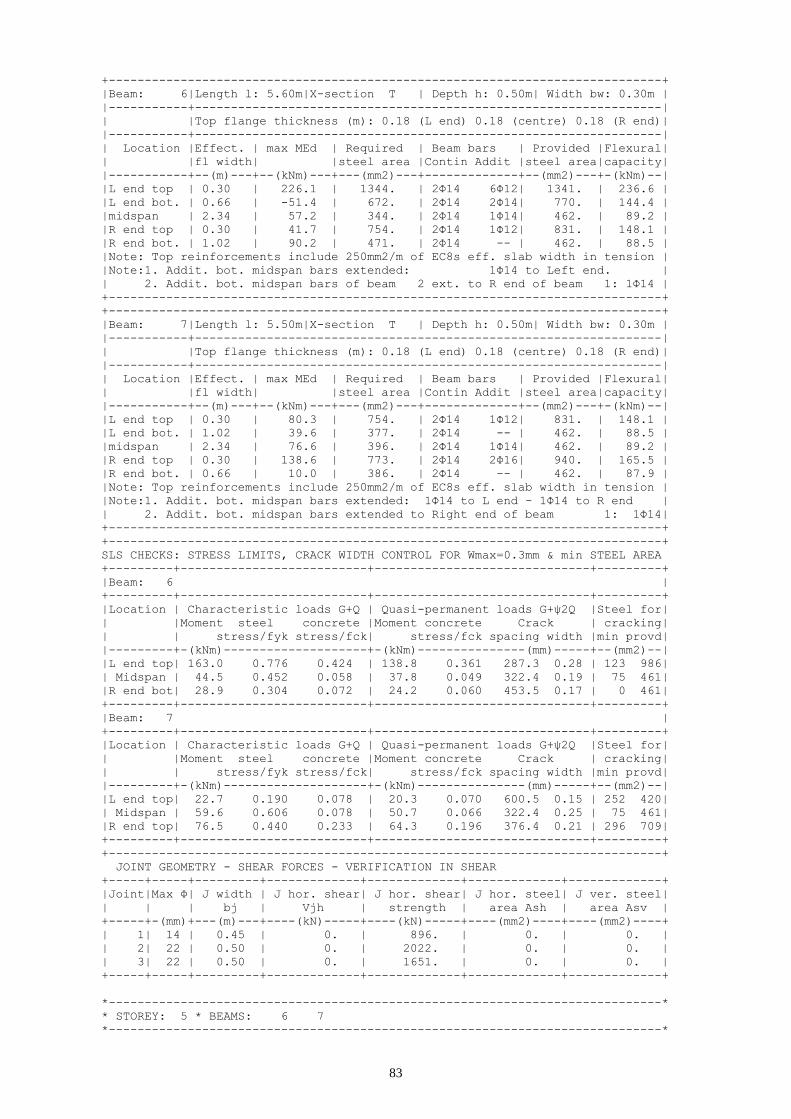
83
+-----------------------------------------------------------------------------+
|Beam: 6|Length l: 5.60m|X-section T | Depth h: 0.50m| Width bw: 0.30m |
|-----------+-----------------------------------------------------------------|
| |Top flange thickness (m): 0.18 (L end) 0.18 (centre) 0.18 (R end)|
|-----------+-----------------------------------------------------------------|
| Location |Effect. | max MEd | Required | Beam bars | Provided |Flexural|
| |fl width| |steel area |Contin Addit |steel area|capacity|
|-----------+--(m)---+--(kNm)---+---(mm2)---+-------------+--(mm2)---+-(kNm)--|
|L end top | 0.30 | 226.1 | 1344. | 2Φ14 6Φ12| 1341. | 236.6 |
|L end bot. | 0.66 | -51.4 | 672. | 2Φ14 2Φ14| 770. | 144.4 |
|midspan | 2.34 | 57.2 | 344. | 2Φ14 1Φ14| 462. | 89.2 |
|R end top | 0.30 | 41.7 | 754. | 2Φ14 1Φ12| 831. | 148.1 |
|R end bot. | 1.02 | 90.2 | 471. | 2Φ14 -- | 462. | 88.5 |
|Note: Top reinforcements include 250mm2/m of EC8s eff. slab width in tension |
|Note:1. Addit. bot. midspan bars extended: 1Φ14 to Left end. |
| 2. Addit. bot. midspan bars of beam 2 ext. to R end of beam 1: 1Φ14 |
+-----------------------------------------------------------------------------+
+-----------------------------------------------------------------------------+
|Beam: 7|Length l: 5.50m|X-section T | Depth h: 0.50m| Width bw: 0.30m |
|-----------+-----------------------------------------------------------------|
| |Top flange thickness (m): 0.18 (L end) 0.18 (centre) 0.18 (R end)|
|-----------+-----------------------------------------------------------------|
| Location |Effect. | max MEd | Required | Beam bars | Provided |Flexural|
| |fl width| |steel area |Contin Addit |steel area|capacity|
|-----------+--(m)---+--(kNm)---+---(mm2)---+-------------+--(mm2)---+-(kNm)--|
|L end top | 0.30 | 80.3 | 754. | 2Φ14 1Φ12| 831. | 148.1 |
|L end bot. | 1.02 | 39.6 | 377. | 2Φ14 -- | 462. | 88.5 |
|midspan | 2.34 | 76.6 | 396. | 2Φ14 1Φ14| 462. | 89.2 |
|R end top | 0.30 | 138.6 | 773. | 2Φ14 2Φ16| 940. | 165.5 |
|R end bot. | 0.66 | 10.0 | 386. | 2Φ14 -- | 462. | 87.9 |
|Note: Top reinforcements include 250mm2/m of EC8s eff. slab width in tension |
|Note:1. Addit. bot. midspan bars extended: 1Φ14 to L end - 1Φ14 to R end |
| 2. Addit. bot. midspan bars extended to Right end of beam 1: 1Φ14|
+-----------------------------------------------------------------------------+
+-----------------------------------------------------------------------------+
SLS CHECKS: STRESS LIMITS, CRACK WIDTH CONTROL FOR Wmax=0.3mm & min STEEL AREA
+---------+--------------------------+------------------------------+---------+
|Beam: 6 |
+---------+--------------------------+------------------------------+---------+
|Location | Characteristic loads G+Q | Quasi-permanent loads G+ψ2Q |Steel for|
| |Moment steel concrete |Moment concrete Crack | cracking|
| | stress/fyk stress/fck| stress/fck spacing width |min provd|
|---------+-(kNm)--------------------+-(kNm)---------------(mm)-----+--(mm2)--|
|L end top| 163.0 0.776 0.424 | 138.8 0.361 287.3 0.28 | 123 986|
| Midspan | 44.5 0.452 0.058 | 37.8 0.049 322.4 0.19 | 75 461|
|R end bot| 28.9 0.304 0.072 | 24.2 0.060 453.5 0.17 | 0 461|
+---------+--------------------------+------------------------------+---------+
|Beam: 7 |
+---------+--------------------------+------------------------------+---------+
|Location | Characteristic loads G+Q | Quasi-permanent loads G+ψ2Q |Steel for|
| |Moment steel concrete |Moment concrete Crack | cracking|
| | stress/fyk stress/fck| stress/fck spacing width |min provd|
|---------+-(kNm)--------------------+-(kNm)---------------(mm)-----+--(mm2)--|
|L end top| 22.7 0.190 0.078 | 20.3 0.070 600.5 0.15 | 252 420|
| Midspan | 59.6 0.606 0.078 | 50.7 0.066 322.4 0.25 | 75 461|
|R end top| 76.5 0.440 0.233 | 64.3 0.196 376.4 0.21 | 296 709|
+---------+--------------------------+------------------------------+---------+
+-----------------------------------------------------------------------------+
JOINT GEOMETRY - SHEAR FORCES - VERIFICATION IN SHEAR
+-----+-----+---------+-------------+-------------+-------------+-------------+
|Joint|Max Φ| J width | J hor. shear| J hor. shear| J hor. steel| J ver. steel|
| | | bj | Vjh | strength | area Ash | area Asv |
+-----+-(mm)+---(m)---+----(kN)-----+----(kN)-----+----(mm2)----+----(mm2)----+
| 1| 14 | 0.45 | 0. | 896. | 0. | 0. |
| 2| 22 | 0.50 | 0. | 2022. | 0. | 0. |
| 3| 22 | 0.50 | 0. | 1651. | 0. | 0. |
+-----+-----+---------+-------------+-------------+-------------+-------------+
*-----------------------------------------------------------------------------*
* STOREY: 5 * BEAMS: 6 7
*-----------------------------------------------------------------------------*

84
* Concrete: C25 - Long. Reinforcement: S500 - Stirrups: S500 - Cover: 35(mm) *
*-----------------------------------------------------------------------------*
GEOMETRY - BENDING MOMENTS MEd - LONGITUDINAL REINFORCEMENT
+-----------------------------------------------------------------------------+
|Beam: 6|Length l: 5.60m|X-section T | Depth h: 0.50m| Width bw: 0.30m |
|-----------+-----------------------------------------------------------------|
| |Top flange thickness (m): 0.18 (L end) 0.18 (centre) 0.18 (R end)|
|-----------+-----------------------------------------------------------------|
| Location |Effect. | max MEd | Required | Beam bars | Provided |Flexural|
| |fl width| |steel area |Contin Addit |steel area|capacity|
|-----------+--(m)---+--(kNm)---+---(mm2)---+-------------+--(mm2)---+-(kNm)--|
|L end top | 0.30 | 302.9 | 1932. | 2Φ14 8Φ14| 1894. | 330.4 |
|L end bot. | 0.66 | -47.9 | 966. | 2Φ14 4Φ14| 1078. | 199.2 |
|midspan | 2.34 | 49.2 | 344. | 2Φ14 1Φ14| 462. | 89.2 |
|R end top | 0.30 | 59.0 | 754. | 2Φ14 1Φ12| 831. | 148.1 |
|R end bot. | 1.02 | 159.7 | 842. | 2Φ14 2Φ14| 924. | 175.8 |
|Note: Top reinforcements include 250mm2/m of EC8s eff. slab width in tension |
|Note:1. Addit. bot. midspan bars extended: 1Φ14 to L end - 1Φ14 to R end |
| 2. Addit. bot. midspan bars of beam 2 ext. to R end of beam 1: 1Φ14 |
+-----------------------------------------------------------------------------+
+-----------------------------------------------------------------------------+
|Beam: 7|Length l: 5.50m|X-section T | Depth h: 0.50m| Width bw: 0.30m |
|-----------+-----------------------------------------------------------------|
| |Top flange thickness (m): 0.18 (L end) 0.18 (centre) 0.18 (R end)|
|-----------+-----------------------------------------------------------------|
| Location |Effect. | max MEd | Required | Beam bars | Provided |Flexural|
| |fl width| |steel area |Contin Addit |steel area|capacity|
|-----------+--(m)---+--(kNm)---+---(mm2)---+-------------+--(mm2)---+-(kNm)--|
|L end top | 0.30 | 123.5 | 754. | 2Φ14 1Φ12| 831. | 148.1 |
|L end bot. | 1.02 | 88.7 | 463. | 2Φ14 -- | 462. | 88.5 |
|midspan | 2.34 | 63.6 | 344. | 2Φ14 1Φ14| 462. | 89.2 |
|R end top | 0.30 | 205.2 | 1200. | 2Φ14 2Φ20| 1166. | 200.2 |
|R end bot. | 0.66 | 31.6 | 600. | 2Φ14 1Φ20| 776. | 145.5 |
|Note: Top reinforcements include 250mm2/m of EC8s eff. slab width in tension |
|Note:1. Addit. bot. midspan bars extended: 1Φ14 to L end - 1Φ14 to R end |
| 2. Addit. bot. midspan bars extended to Right end of beam 1: 1Φ14|
+-----------------------------------------------------------------------------+
+-----------------------------------------------------------------------------+
SLS CHECKS: STRESS LIMITS, CRACK WIDTH CONTROL FOR Wmax=0.3mm & min STEEL AREA
+---------+--------------------------+------------------------------+---------+
|Beam: 6 |
+---------+--------------------------+------------------------------+---------+
|Location | Characteristic loads G+Q | Quasi-permanent loads G+ψ2Q |Steel for|
| |Moment steel concrete |Moment concrete Crack | cracking|
| | stress/fyk stress/fck| stress/fck spacing width |min provd|
|---------+-(kNm)--------------------+-(kNm)---------------(mm)-----+--(mm2)--|
|L end top| 205.9 0.655 0.438 | 175.4 0.373 243.0 0.20 | 150 1539|
| Midspan | 38.3 0.389 0.050 | 32.6 0.043 322.4 0.16 | 75 461|
|R end bot| 59.4 0.318 0.112 | 50.3 0.095 312.0 0.13 | 0 929|
+---------+--------------------------+------------------------------+---------+
|Beam: 7 |
+---------+--------------------------+------------------------------+---------+
|Location | Characteristic loads G+Q | Quasi-permanent loads G+ψ2Q |Steel for|
| |Moment steel concrete |Moment concrete Crack | cracking|
| | stress/fyk stress/fck| stress/fck spacing width |min provd|
|---------+-(kNm)--------------------+-(kNm)---------------(mm)-----+--(mm2)--|
|L end top| 18.8 0.158 0.065 | 17.4 0.060 600.5 0.13 | 252 420|
| Midspan | 49.5 0.503 0.065 | 42.0 0.055 322.4 0.21 | 75 461|
|R end top| 103.4 0.475 0.266 | 86.8 0.223 351.2 0.21 | 335 936|
+---------+--------------------------+------------------------------+---------+
+-----------------------------------------------------------------------------+
JOINT GEOMETRY - SHEAR FORCES - VERIFICATION IN SHEAR
+-----+-----+---------+-------------+-------------+-------------+-------------+
|Joint|Max Φ| J width | J hor. shear| J hor. shear| J hor. steel| J ver. steel|
| | | bj | Vjh | strength | area Ash | area Asv |
+-----+-(mm)+---(m)---+----(kN)-----+----(kN)-----+----(mm2)----+----(mm2)----+
| 1| 14 | 0.45 | 0. | 822. | 0. | 0. |
| 2| 24 | 0.50 | 0. | 1852. | 0. | 0. |
| 3| 24 | 0.50 | 0. | 1534. | 0. | 0. |
+-----+-----+---------+-------------+-------------+-------------+-------------+

85
*-----------------------------------------------------------------------------*
* STOREY: 4 * BEAMS: 6 7
*-----------------------------------------------------------------------------*
* Concrete: C25 - Long. Reinforcement: S500 - Stirrups: S500 - Cover: 35(mm) *
*-----------------------------------------------------------------------------*
GEOMETRY - BENDING MOMENTS MEd - LONGITUDINAL REINFORCEMENT
+-----------------------------------------------------------------------------+
|Beam: 6|Length l: 5.60m|X-section T | Depth h: 0.50m| Width bw: 0.30m |
|-----------+-----------------------------------------------------------------|
| |Top flange thickness (m): 0.18 (L end) 0.18 (centre) 0.18 (R end)|
|-----------+-----------------------------------------------------------------|
| Location |Effect. | max MEd | Required | Beam bars | Provided |Flexural|
| |fl width| |steel area |Contin Addit |steel area|capacity|
|-----------+--(m)---+--(kNm)---+---(mm2)---+-------------+--(mm2)---+-(kNm)--|
|L end top | 0.30 | 300.9 | 1915. | 2Φ14 8Φ14| 1894. | 330.4 |
|L end bot. | 0.66 | -29.2 | 957. | 2Φ14 4Φ14| 1078. | 199.2 |
|midspan | 2.34 | 51.2 | 344. | 2Φ14 1Φ14| 462. | 89.2 |
|R end top | 0.30 | 73.1 | 754. | 2Φ14 1Φ12| 831. | 148.1 |
|R end bot. | 1.02 | 158.3 | 835. | 2Φ14 2Φ14| 930. | 175.8 |
|Note: Top reinforcements include 250mm2/m of EC8s eff. slab width in tension |
|Note:1. Addit. bot. midspan bars extended: 1Φ14 to L end - 1Φ14 to R end |
| 2. Addit. bot. midspan bars of beam 2 ext. to R end of beam 1: 1Φ14 |
+-----------------------------------------------------------------------------+
+-----------------------------------------------------------------------------+
|Beam: 7|Length l: 5.50m|X-section T | Depth h: 0.50m| Width bw: 0.30m |
|-----------+-----------------------------------------------------------------|
| |Top flange thickness (m): 0.18 (L end) 0.18 (centre) 0.18 (R end)|
|-----------+-----------------------------------------------------------------|
| Location |Effect. | max MEd | Required | Beam bars | Provided |Flexural|
| |fl width| |steel area |Contin Addit |steel area|capacity|
|-----------+--(m)---+--(kNm)---+---(mm2)---+-------------+--(mm2)---+-(kNm)--|
|L end top | 0.30 | 132.6 | 754. | 2Φ14 1Φ12| 831. | 148.1 |
|L end bot. | 1.02 | 92.1 | 481. | 2Φ14 -- | 462. | 88.5 |
|midspan | 2.34 | 65.1 | 344. | 2Φ14 1Φ14| 462. | 89.2 |
|R end top | 0.30 | 207.0 | 1212. | 2Φ14 2Φ20| 1166. | 200.2 |
|R end bot. | 0.66 | 44.9 | 606. | 2Φ14 1Φ20| 776. | 145.5 |
|Note: Top reinforcements include 250mm2/m of EC8s eff. slab width in tension |
|Note:1. Addit. bot. midspan bars extended: 1Φ14 to L end - 1Φ14 to R end |
| 2. Addit. bot. midspan bars extended to Right end of beam 1: 1Φ14|
+-----------------------------------------------------------------------------+
+-----------------------------------------------------------------------------+
SLS CHECKS: STRESS LIMITS, CRACK WIDTH CONTROL FOR Wmax=0.3mm & min STEEL AREA
+---------+--------------------------+------------------------------+---------+
|Beam: 6 |
+---------+--------------------------+------------------------------+---------+
|Location | Characteristic loads G+Q | Quasi-permanent loads G+ψ2Q |Steel for|
| |Moment steel concrete |Moment concrete Crack | cracking|
| | stress/fyk stress/fck| stress/fck spacing width |min provd|
|---------+-(kNm)--------------------+-(kNm)---------------(mm)-----+--(mm2)--|
|L end top| 193.8 0.616 0.412 | 165.0 0.351 243.0 0.19 | 150 1539|
| Midspan | 39.8 0.405 0.052 | 33.9 0.044 322.4 0.17 | 75 461|
|R end bot| 50.3 0.269 0.095 | 42.6 0.080 312.0 0.11 | 0 929|
+---------+--------------------------+------------------------------+---------+
|Beam: 7 |
+---------+--------------------------+------------------------------+---------+
|Location | Characteristic loads G+Q | Quasi-permanent loads G+ψ2Q |Steel for|
| |Moment steel concrete |Moment concrete Crack | cracking|
| | stress/fyk stress/fck| stress/fck spacing width |min provd|
|---------+-(kNm)--------------------+-(kNm)---------------(mm)-----+--(mm2)--|
|L end top| 22.3 0.187 0.077 | 20.3 0.070 600.5 0.15 | 252 420|
| Midspan | 50.7 0.515 0.066 | 43.1 0.056 322.4 0.21 | 75 461|
|R end top| 96.6 0.444 0.248 | 81.1 0.208 351.2 0.20 | 335 936|
+---------+--------------------------+------------------------------+---------+
+-----------------------------------------------------------------------------+
JOINT GEOMETRY - SHEAR FORCES - VERIFICATION IN SHEAR
+-----+-----+---------+-------------+-------------+-------------+-------------+
|Joint|Max Φ| J width | J hor. shear| J hor. shear| J hor. steel| J ver. steel|
| | | bj | Vjh | strength | area Ash | area Asv |
+-----+-(mm)+---(m)---+----(kN)-----+----(kN)-----+----(mm2)----+----(mm2)----+
| 1| 14 | 0.45 | 0. | 741. | 0. | 0. |
| 2| 24 | 0.50 | 0. | 1659. | 0. | 0. |
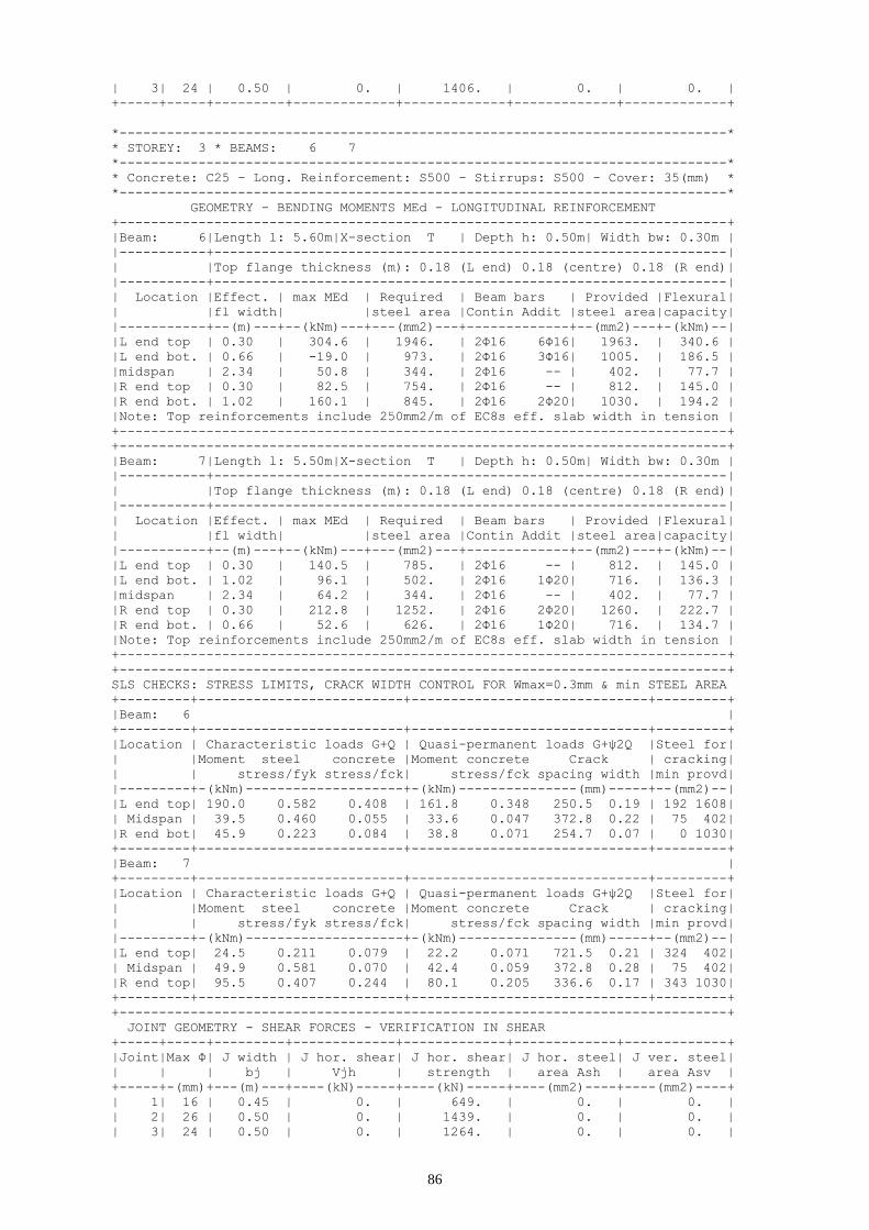
86
| 3| 24 | 0.50 | 0. | 1406. | 0. | 0. |
+-----+-----+---------+-------------+-------------+-------------+-------------+
*-----------------------------------------------------------------------------*
* STOREY: 3 * BEAMS: 6 7
*-----------------------------------------------------------------------------*
* Concrete: C25 - Long. Reinforcement: S500 - Stirrups: S500 - Cover: 35(mm) *
*-----------------------------------------------------------------------------*
GEOMETRY - BENDING MOMENTS MEd - LONGITUDINAL REINFORCEMENT
+-----------------------------------------------------------------------------+
|Beam: 6|Length l: 5.60m|X-section T | Depth h: 0.50m| Width bw: 0.30m |
|-----------+-----------------------------------------------------------------|
| |Top flange thickness (m): 0.18 (L end) 0.18 (centre) 0.18 (R end)|
|-----------+-----------------------------------------------------------------|
| Location |Effect. | max MEd | Required | Beam bars | Provided |Flexural|
| |fl width| |steel area |Contin Addit |steel area|capacity|
|-----------+--(m)---+--(kNm)---+---(mm2)---+-------------+--(mm2)---+-(kNm)--|
|L end top | 0.30 | 304.6 | 1946. | 2Φ16 6Φ16| 1963. | 340.6 |
|L end bot. | 0.66 | -19.0 | 973. | 2Φ16 3Φ16| 1005. | 186.5 |
|midspan | 2.34 | 50.8 | 344. | 2Φ16 -- | 402. | 77.7 |
|R end top | 0.30 | 82.5 | 754. | 2Φ16 -- | 812. | 145.0 |
|R end bot. | 1.02 | 160.1 | 845. | 2Φ16 2Φ20| 1030. | 194.2 |
|Note: Top reinforcements include 250mm2/m of EC8s eff. slab width in tension |
+-----------------------------------------------------------------------------+
+-----------------------------------------------------------------------------+
|Beam: 7|Length l: 5.50m|X-section T | Depth h: 0.50m| Width bw: 0.30m |
|-----------+-----------------------------------------------------------------|
| |Top flange thickness (m): 0.18 (L end) 0.18 (centre) 0.18 (R end)|
|-----------+-----------------------------------------------------------------|
| Location |Effect. | max MEd | Required | Beam bars | Provided |Flexural|
| |fl width| |steel area |Contin Addit |steel area|capacity|
|-----------+--(m)---+--(kNm)---+---(mm2)---+-------------+--(mm2)---+-(kNm)--|
|L end top | 0.30 | 140.5 | 785. | 2Φ16 -- | 812. | 145.0 |
|L end bot. | 1.02 | 96.1 | 502. | 2Φ16 1Φ20| 716. | 136.3 |
|midspan | 2.34 | 64.2 | 344. | 2Φ16 -- | 402. | 77.7 |
|R end top | 0.30 | 212.8 | 1252. | 2Φ16 2Φ20| 1260. | 222.7 |
|R end bot. | 0.66 | 52.6 | 626. | 2Φ16 1Φ20| 716. | 134.7 |
|Note: Top reinforcements include 250mm2/m of EC8s eff. slab width in tension |
+-----------------------------------------------------------------------------+
+-----------------------------------------------------------------------------+
SLS CHECKS: STRESS LIMITS, CRACK WIDTH CONTROL FOR Wmax=0.3mm & min STEEL AREA
+---------+--------------------------+------------------------------+---------+
|Beam: 6 |
+---------+--------------------------+------------------------------+---------+
|Location | Characteristic loads G+Q | Quasi-permanent loads G+ψ2Q |Steel for|
| |Moment steel concrete |Moment concrete Crack | cracking|
| | stress/fyk stress/fck| stress/fck spacing width |min provd|
|---------+-(kNm)--------------------+-(kNm)---------------(mm)-----+--(mm2)--|
|L end top| 190.0 0.582 0.408 | 161.8 0.348 250.5 0.19 | 192 1608|
| Midspan | 39.5 0.460 0.055 | 33.6 0.047 372.8 0.22 | 75 402|
|R end bot| 45.9 0.223 0.084 | 38.8 0.071 254.7 0.07 | 0 1030|
+---------+--------------------------+------------------------------+---------+
|Beam: 7 |
+---------+--------------------------+------------------------------+---------+
|Location | Characteristic loads G+Q | Quasi-permanent loads G+ψ2Q |Steel for|
| |Moment steel concrete |Moment concrete Crack | cracking|
| | stress/fyk stress/fck| stress/fck spacing width |min provd|
|---------+-(kNm)--------------------+-(kNm)---------------(mm)-----+--(mm2)--|
|L end top| 24.5 0.211 0.079 | 22.2 0.071 721.5 0.21 | 324 402|
| Midspan | 49.9 0.581 0.070 | 42.4 0.059 372.8 0.28 | 75 402|
|R end top| 95.5 0.407 0.244 | 80.1 0.205 336.6 0.17 | 343 1030|
+---------+--------------------------+------------------------------+---------+
+-----------------------------------------------------------------------------+
JOINT GEOMETRY - SHEAR FORCES - VERIFICATION IN SHEAR
+-----+-----+---------+-------------+-------------+-------------+-------------+
|Joint|Max Φ| J width | J hor. shear| J hor. shear| J hor. steel| J ver. steel|
| | | bj | Vjh | strength | area Ash | area Asv |
+-----+-(mm)+---(m)---+----(kN)-----+----(kN)-----+----(mm2)----+----(mm2)----+
| 1| 16 | 0.45 | 0. | 649. | 0. | 0. |
| 2| 26 | 0.50 | 0. | 1439. | 0. | 0. |
| 3| 24 | 0.50 | 0. | 1264. | 0. | 0. |

87
+-----+-----+---------+-------------+-------------+-------------+-------------+
*-----------------------------------------------------------------------------*
* STOREY: 2 * BEAMS: 6 7
*-----------------------------------------------------------------------------*
* Concrete: C25 - Long. Reinforcement: S500 - Stirrups: S500 - Cover: 35(mm) *
*-----------------------------------------------------------------------------*
GEOMETRY - BENDING MOMENTS MEd - LONGITUDINAL REINFORCEMENT
+-----------------------------------------------------------------------------+
|Beam: 6|Length l: 5.60m|X-section T | Depth h: 0.50m| Width bw: 0.30m |
|-----------+-----------------------------------------------------------------|
| |Top flange thickness (m): 0.18 (L end) 0.18 (centre) 0.18 (R end)|
|-----------+-----------------------------------------------------------------|
| Location |Effect. | max MEd | Required | Beam bars | Provided |Flexural|
| |fl width| |steel area |Contin Addit |steel area|capacity|
|-----------+--(m)---+--(kNm)---+---(mm2)---+-------------+--(mm2)---+-(kNm)--|
|L end top | 0.30 | 297.0 | 1883. | 2Φ16 7Φ14| 1835. | 320.0 |
|L end bot. | 0.66 | -16.8 | 941. | 2Φ16 3Φ16| 1005. | 186.5 |
|midspan | 2.34 | 50.5 | 344. | 2Φ16 -- | 402. | 77.7 |
|R end top | 0.30 | 86.4 | 754. | 2Φ16 -- | 812. | 145.0 |
|R end bot. | 1.02 | 153.3 | 808. | 2Φ16 2Φ20| 1030. | 194.2 |
|Note: Top reinforcements include 250mm2/m of EC8s eff. slab width in tension |
+-----------------------------------------------------------------------------+
+-----------------------------------------------------------------------------+
|Beam: 7|Length l: 5.50m|X-section T | Depth h: 0.50m| Width bw: 0.30m |
|-----------+-----------------------------------------------------------------|
| |Top flange thickness (m): 0.18 (L end) 0.18 (centre) 0.18 (R end)|
|-----------+-----------------------------------------------------------------|
| Location |Effect. | max MEd | Required | Beam bars | Provided |Flexural|
| |fl width| |steel area |Contin Addit |steel area|capacity|
|-----------+--(m)---+--(kNm)---+---(mm2)---+-------------+--(mm2)---+-(kNm)--|
|L end top | 0.30 | 143.2 | 801. | 2Φ16 -- | 812. | 145.0 |
|L end bot. | 1.02 | 93.1 | 486. | 2Φ16 1Φ20| 716. | 136.3 |
|midspan | 2.34 | 63.2 | 344. | 2Φ16 -- | 402. | 77.7 |
|R end top | 0.30 | 210.1 | 1233. | 2Φ16 2Φ20| 1260. | 222.7 |
|R end bot. | 0.66 | 53.6 | 616. | 2Φ16 1Φ20| 716. | 134.7 |
|Note: Top reinforcements include 250mm2/m of EC8s eff. slab width in tension |
+-----------------------------------------------------------------------------+
+-----------------------------------------------------------------------------+
SLS CHECKS: STRESS LIMITS, CRACK WIDTH CONTROL FOR Wmax=0.3mm & min STEEL AREA
+---------+--------------------------+------------------------------+---------+
|Beam: 6 |
+---------+--------------------------+------------------------------+---------+
|Location | Characteristic loads G+Q | Quasi-permanent loads G+ψ2Q |Steel for|
| |Moment steel concrete |Moment concrete Crack | cracking|
| | stress/fyk stress/fck| stress/fck spacing width |min provd|
|---------+-(kNm)--------------------+-(kNm)---------------(mm)-----+--(mm2)--|
|L end top| 184.3 0.608 0.404 | 156.9 0.344 250.5 0.19 | 159 1479|
| Midspan | 39.2 0.456 0.055 | 33.4 0.047 372.8 0.22 | 75 402|
|R end bot| 39.6 0.192 0.073 | 33.5 0.061 254.7 0.06 | 0 1030|
+---------+--------------------------+------------------------------+---------+
|Beam: 7 |
+---------+--------------------------+------------------------------+---------+
|Location | Characteristic loads G+Q | Quasi-permanent loads G+ψ2Q |Steel for|
| |Moment steel concrete |Moment concrete Crack | cracking|
| | stress/fyk stress/fck| stress/fck spacing width |min provd|
|---------+-(kNm)--------------------+-(kNm)---------------(mm)-----+--(mm2)--|
|L end top| 27.8 0.239 0.089 | 25.0 0.080 721.5 0.23 | 324 402|
| Midspan | 49.1 0.572 0.069 | 41.8 0.058 372.8 0.27 | 75 402|
|R end top| 93.3 0.398 0.239 | 78.2 0.200 336.6 0.17 | 343 1030|
+---------+--------------------------+------------------------------+---------+
+-----------------------------------------------------------------------------+
JOINT GEOMETRY - SHEAR FORCES - VERIFICATION IN SHEAR
+-----+-----+---------+-------------+-------------+-------------+-------------+
|Joint|Max Φ| J width | J hor. shear| J hor. shear| J hor. steel| J ver. steel|
| | | bj | Vjh | strength | area Ash | area Asv |
+-----+-(mm)+---(m)---+----(kN)-----+----(kN)-----+----(mm2)----+----(mm2)----+
| 1| 16 | 0.45 | 0. | 544. | 0. | 0. |
| 2| 28 | 0.50 | 0. | 1176. | 0. | 0. |
| 3| 26 | 0.50 | 0. | 1104. | 0. | 0. |
+-----+-----+---------+-------------+-------------+-------------+-------------+

88
*-----------------------------------------------------------------------------*
* STOREY: 1 * BEAMS: 6 7
*-----------------------------------------------------------------------------*
* Concrete: C25 - Long. Reinforcement: S500 - Stirrups: S500 - Cover: 35(mm) *
*-----------------------------------------------------------------------------*
GEOMETRY - BENDING MOMENTS MEd - LONGITUDINAL REINFORCEMENT
+-----------------------------------------------------------------------------+
|Beam: 6|Length l: 5.60m|X-section T | Depth h: 0.50m| Width bw: 0.30m |
|-----------+-----------------------------------------------------------------|
| |Top flange thickness (m): 0.18 (L end) 0.18 (centre) 0.18 (R end)|
|-----------+-----------------------------------------------------------------|
| Location |Effect. | max MEd | Required | Beam bars | Provided |Flexural|
| |fl width| |steel area |Contin Addit |steel area|capacity|
|-----------+--(m)---+--(kNm)---+---(mm2)---+-------------+--(mm2)---+-(kNm)--|
|L end top | 0.30 | 270.1 | 1668. | 2Φ16 6Φ14| 1681. | 293.2 |
|L end bot. | 0.66 | -15.8 | 834. | 2Φ16 2Φ16| 804. | 150.6 |
|midspan | 2.34 | 52.3 | 344. | 2Φ16 -- | 402. | 77.7 |
|R end top | 0.30 | 81.6 | 754. | 2Φ16 -- | 812. | 145.0 |
|R end bot. | 1.02 | 125.4 | 658. | 2Φ16 1Φ20| 716. | 136.3 |
|Note: Top reinforcements include 250mm2/m of EC8s eff. slab width in tension |
+-----------------------------------------------------------------------------+
+-----------------------------------------------------------------------------+
|Beam: 7|Length l: 5.50m|X-section T | Depth h: 0.50m| Width bw: 0.30m |
|-----------+-----------------------------------------------------------------|
| |Top flange thickness (m): 0.18 (L end) 0.18 (centre) 0.18 (R end)|
|-----------+-----------------------------------------------------------------|
| Location |Effect. | max MEd | Required | Beam bars | Provided |Flexural|
| |fl width| |steel area |Contin Addit |steel area|capacity|
|-----------+--(m)---+--(kNm)---+---(mm2)---+-------------+--(mm2)---+-(kNm)--|
|L end top | 0.30 | 129.9 | 754. | 2Φ16 -- | 812. | 145.0 |
|L end bot. | 1.02 | 70.8 | 377. | 2Φ16 -- | 402. | 77.2 |
|midspan | 2.34 | 63.5 | 344. | 2Φ16 -- | 402. | 77.7 |
|R end top | 0.30 | 187.9 | 1084. | 2Φ16 3Φ14| 1094. | 189.3 |
|R end bot. | 0.66 | 43.1 | 542. | 2Φ16 1Φ20| 716. | 134.7 |
|Note: Top reinforcements include 250mm2/m of EC8s eff. slab width in tension |
+-----------------------------------------------------------------------------+
+-----------------------------------------------------------------------------+
SLS CHECKS: STRESS LIMITS, CRACK WIDTH CONTROL FOR Wmax=0.3mm & min STEEL AREA
+---------+--------------------------+------------------------------+---------+
|Beam: 6 |
+---------+--------------------------+------------------------------+---------+
|Location | Characteristic loads G+Q | Quasi-permanent loads G+ψ2Q |Steel for|
| |Moment steel concrete |Moment concrete Crack | cracking|
| | stress/fyk stress/fck| stress/fck spacing width |min provd|
|---------+-(kNm)--------------------+-(kNm)---------------(mm)-----+--(mm2)--|
|L end top| 167.9 0.615 0.401 | 142.9 0.341 263.1 0.21 | 160 1325|
| Midspan | 40.7 0.473 0.057 | 34.6 0.048 372.8 0.22 | 75 402|
|R end bot| 26.1 0.180 0.055 | 21.9 0.046 304.7 0.07 | 0 716|
+---------+--------------------------+------------------------------+---------+
|Beam: 7 |
+---------+--------------------------+------------------------------+---------+
|Location | Characteristic loads G+Q | Quasi-permanent loads G+ψ2Q |Steel for|
| |Moment steel concrete |Moment concrete Crack | cracking|
| | stress/fyk stress/fck| stress/fck spacing width |min provd|
|---------+-(kNm)--------------------+-(kNm)---------------(mm)-----+--(mm2)--|
|L end top| 33.1 0.286 0.118 | 29.6 0.105 706.2 0.27 | 324 402|
| Midspan | 49.4 0.574 0.069 | 41.9 0.059 372.8 0.27 | 75 402|
|R end top| 86.4 0.425 0.231 | 72.4 0.193 334.9 0.18 | 292 863|
+---------+--------------------------+------------------------------+---------+
+-----------------------------------------------------------------------------+
JOINT GEOMETRY - SHEAR FORCES - VERIFICATION IN SHEAR
+-----+-----+---------+-------------+-------------+-------------+-------------+
|Joint|Max Φ| J width | J hor. shear| J hor. shear| J hor. steel| J ver. steel|
| | | bj | Vjh | strength | area Ash | area Asv |
+-----+-(mm)+---(m)---+----(kN)-----+----(kN)-----+----(mm2)----+----(mm2)----+
| 1| 16 | 0.45 | 0. | 418. | 0. | 0. |
| 2| 28 | 0.50 | 0. | 816. | 0. | 0. |
| 3| 26 | 0.50 | 0. | 919. | 0. | 0. |
+-----+-----+---------+-------------+-------------+-------------+-------------+
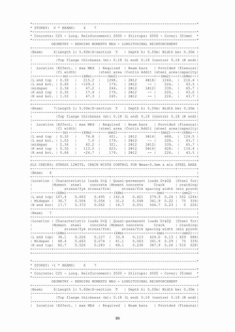
89
*-----------------------------------------------------------------------------*
* STOREY: 0 * BEAMS: 6 7
*-----------------------------------------------------------------------------*
* Concrete: C25 - Long. Reinforcement: S500 - Stirrups: S500 - Cover: 35(mm) *
*-----------------------------------------------------------------------------*
GEOMETRY - BENDING MOMENTS MEd - LONGITUDINAL REINFORCEMENT
+-----------------------------------------------------------------------------+
|Beam: 6|Length l: 5.60m|X-section T | Depth h: 0.50m| Width bw: 0.30m |
|-----------+-----------------------------------------------------------------|
| |Top flange thickness (m): 0.18 (L end) 0.18 (centre) 0.18 (R end)|
|-----------+-----------------------------------------------------------------|
| Location |Effect. | max MEd | Required | Beam bars | Provided |Flexural|
| |fl width| |steel area |Contin Addit |steel area|capacity|
|-----------+--(m)---+--(kNm)---+---(mm2)---+-------------+--(mm2)---+-(kNm)--|
|L end top | 0.30 | 215.2 | 1268. | 2Φ12 4Φ18| 1244. | 216.4 |
|L end bot. | 0.66 | -109.3 | 179. | 2Φ12 -- | 226. | 43.5 |
|midspan | 2.34 | 47.2 | 244. | 2Φ12 1Φ12| 339. | 65.7 |
|R end top | 0.30 | 17.9 | 179. | 2Φ12 -- | 226. | 43.0 |
|R end bot. | 1.02 | 47.3 | 245. | 2Φ12 -- | 226. | 43.7 |
+-----------------------------------------------------------------------------+
+-----------------------------------------------------------------------------+
|Beam: 7|Length l: 5.50m|X-section T | Depth h: 0.50m| Width bw: 0.30m |
|-----------+-----------------------------------------------------------------|
| |Top flange thickness (m): 0.18 (L end) 0.18 (centre) 0.18 (R end)|
|-----------+-----------------------------------------------------------------|
| Location |Effect. | max MEd | Required | Beam bars | Provided |Flexural|
| |fl width| |steel area |Contin Addit |steel area|capacity|
|-----------+--(m)---+--(kNm)---+---(mm2)---+-------------+--(mm2)---+-(kNm)--|
|L end top | 0.30 | 74.8 | 401. | 2Φ12 3Φ14| 688. | 124.5 |
|L end bot. | 1.02 | 7.0 | 179. | 2Φ12 -- | 226. | 43.7 |
|midspan | 2.34 | 62.2 | 321. | 2Φ12 1Φ12| 339. | 65.7 |
|R end top | 0.30 | 113.5 | 623. | 2Φ12 2Φ16| 628. | 114.4 |
|R end bot. | 0.66 | -24.7 | 179. | 2Φ12 -- | 226. | 43.5 |
+-----------------------------------------------------------------------------+
+-----------------------------------------------------------------------------+
SLS CHECKS: STRESS LIMITS, CRACK WIDTH CONTROL FOR Wmax=0.3mm & min STEEL AREA
+---------+--------------------------+------------------------------+---------+
|Beam: 6 |
+---------+--------------------------+------------------------------+---------+
|Location | Characteristic loads G+Q | Quasi-permanent loads G+ψ2Q |Steel for|
| |Moment steel concrete |Moment concrete Crack | cracking|
| | stress/fyk stress/fck| stress/fck spacing width |min provd|
|---------+-(kNm)--------------------+-(kNm)---------------(mm)-----+--(mm2)--|
|L end top| 167.4 0.663 0.495 | 142.4 0.421 279.9 0.24 | 552 1244|
| Midspan | 36.7 0.504 0.056 | 31.2 0.048 341.9 0.22 | 75 339|
|R end bot| 17.7 0.373 0.062 | 14.7 0.051 504.7 0.23 | 0 226|
+---------+--------------------------+------------------------------+---------+
|Beam: 7 |
+---------+--------------------------+------------------------------+---------+
|Location | Characteristic loads G+Q | Quasi-permanent loads G+ψ2Q |Steel for|
| |Moment steel concrete |Moment concrete Crack | cracking|
| | stress/fyk stress/fck| stress/fck spacing width |min provd|
|---------+-(kNm)--------------------+-(kNm)---------------(mm)-----+--(mm2)--|
|L end top| 38.1 0.226 0.127 | 33.9 0.113 429.0 0.13 | 659 688|
| Midspan | 48.4 0.663 0.074 | 41.1 0.063 341.9 0.29 | 75 339|
|R end top| 82.7 0.526 0.283 | 69.1 0.236 387.9 0.26 | 510 628|
+---------+--------------------------+------------------------------+---------+
+-----------------------------------------------------------------------------+
*-----------------------------------------------------------------------------*
* STOREY: -1 * BEAMS: 6 7
*-----------------------------------------------------------------------------*
* Concrete: C25 - Long. Reinforcement: S500 - Stirrups: S500 - Cover: 35(mm) *
*-----------------------------------------------------------------------------*
GEOMETRY - BENDING MOMENTS MEd - LONGITUDINAL REINFORCEMENT
+-----------------------------------------------------------------------------+
|Beam: 6|Length l: 5.60m|X-section T | Depth h: 0.50m| Width bw: 0.30m |
|-----------+-----------------------------------------------------------------|
| |Top flange thickness (m): 0.18 (L end) 0.18 (centre) 0.18 (R end)|
|-----------+-----------------------------------------------------------------|
| Location |Effect. | max MEd | Required | Beam bars | Provided |Flexural|

90
| |fl width| |steel area |Contin Addit |steel area|capacity|
|-----------+--(m)---+--(kNm)---+---(mm2)---+-------------+--(mm2)---+-(kNm)--|
|L end top | 0.30 | 177.1 | 1014. | 2Φ12 3Φ18| 990. | 173.3 |
|L end bot. | 0.66 | -114.2 | 179. | 2Φ12 -- | 226. | 43.5 |
|midspan | 2.34 | 53.5 | 276. | 2Φ12 1Φ12| 339. | 65.7 |
|R end top | 0.30 | 4.8 | 179. | 2Φ12 4Φ12| 679. | 122.9 |
|R end bot. | 1.02 | 0.3 | 179. | 2Φ12 -- | 226. | 43.7 |
+-----------------------------------------------------------------------------+
+-----------------------------------------------------------------------------+
|Beam: 7|Length l: 5.50m|X-section T | Depth h: 0.50m| Width bw: 0.30m |
|-----------+-----------------------------------------------------------------|
| |Top flange thickness (m): 0.18 (L end) 0.18 (centre) 0.18 (R end)|
|-----------+-----------------------------------------------------------------|
| Location |Effect. | max MEd | Required | Beam bars | Provided |Flexural|
| |fl width| |steel area |Contin Addit |steel area|capacity|
|-----------+--(m)---+--(kNm)---+---(mm2)---+-------------+--(mm2)---+-(kNm)--|
|L end top | 0.30 | 60.9 | 324. | 2Φ12 4Φ12| 679. | 122.9 |
|L end bot. | 1.02 | -36.5 | 179. | 2Φ12 -- | 226. | 43.7 |
|midspan | 2.34 | 59.9 | 309. | 2Φ12 1Φ12| 339. | 65.7 |
|R end top | 0.30 | 97.3 | 529. | 2Φ12 1Φ20| 541. | 99.0 |
|R end bot. | 0.66 | -59.3 | 179. | 2Φ12 -- | 226. | 43.5 |
+-----------------------------------------------------------------------------+
+-----------------------------------------------------------------------------+
SLS CHECKS: STRESS LIMITS, CRACK WIDTH CONTROL FOR Wmax=0.3mm & min STEEL AREA
+---------+--------------------------+------------------------------+---------+
|Beam: 6 |
+---------+--------------------------+------------------------------+---------+
|Location | Characteristic loads G+Q | Quasi-permanent loads G+ψ2Q |Steel for|
| |Moment steel concrete |Moment concrete Crack | cracking|
| | stress/fyk stress/fck| stress/fck spacing width |min provd|
|---------+-(kNm)--------------------+-(kNm)---------------(mm)-----+--(mm2)--|
|L end top| 137.7 0.665 0.432 | 117.1 0.368 316.6 0.27 | 548 989|
| Midspan | 41.6 0.571 0.063 | 35.4 0.054 341.9 0.25 | 75 339|
|R end top| 2.2 0.015 0.008 | 2.3 0.008 411.4 0.01 | 629 678|
+---------+--------------------------+------------------------------+---------+
|Beam: 7 |
+---------+--------------------------+------------------------------+---------+
|Location | Characteristic loads G+Q | Quasi-permanent loads G+ψ2Q |Steel for|
| |Moment steel concrete |Moment concrete Crack | cracking|
| | stress/fyk stress/fck| stress/fck spacing width |min provd|
|---------+-(kNm)--------------------+-(kNm)---------------(mm)-----+--(mm2)--|
|L end top| 46.8 0.281 0.157 | 41.4 0.139 405.3 0.15 | 629 678|
| Midspan | 46.6 0.639 0.071 | 39.6 0.060 341.9 0.28 | 75 339|
|R end top| 76.1 0.383 0.242 | 63.5 0.202 353.3 0.17 | 558 541|
+---------+--------------------------+------------------------------+---------+
+-----------------------------------------------------------------------------+
6.3 Frame C
*-----------------------------------------------------------------------------*
* STOREY: 6 * BEAMS: 10 11 12 13 14
*-----------------------------------------------------------------------------*
* Concrete: C25 - Long. Reinforcement: S500 - Stirrups: S500 - Cover: 35(mm) *
*-----------------------------------------------------------------------------*
GEOMETRY - BENDING MOMENTS MEd - LONGITUDINAL REINFORCEMENT
+-----------------------------------------------------------------------------+
|Beam: 10|Length l: 5.50m|X-section InvL | Depth h: 0.50m| Width bw: 0.30m |
|-----------+-----------------------------------------------------------------|
| |Top flange thickness (m): 0.18 (L end) 0.18 (centre) 0.18 (R end)|
|-----------+-----------------------------------------------------------------|
| Location |Effect. | max MEd | Required | Beam bars | Provided |Flexural|
| |fl width| |steel area |Contin Addit |steel area|capacity|
|-----------+--(m)---+--(kNm)---+---(mm2)---+-------------+--(mm2)---+-(kNm)--|
|L end top | 0.30 | 76.7 | 471. | 2Φ14 1Φ12| 548. | 100.7 |
|L end bot. | 0.48 | 11.6 | 344. | 2Φ14 -- | 462. | 87.2 |
|midspan | 1.32 | 47.4 | 344. | 2Φ14 1Φ14| 462. | 88.8 |
|R end top | 0.30 | 58.0 | 524. | 2Φ14 1Φ12| 601. | 109.8 |
|R end bot. | 0.66 | 60.4 | 344. | 2Φ14 -- | 462. | 87.9 |
|Note: Top reinforcements include 250mm2/m of EC8s eff. slab width in tension |
|Note:1. Addit. bot. midspan bars extended: 1Φ14 to Left end. |

91
| 2. Addit. bot. midspan bars of beam 2 ext. to R end of beam 1: 1Φ14 |
+-----------------------------------------------------------------------------+
+-----------------------------------------------------------------------------+
|Beam: 11|Length l: 5.30m|X-section InvL | Depth h: 0.50m| Width bw: 0.30m |
|-----------+-----------------------------------------------------------------|
| |Top flange thickness (m): 0.18 (L end) 0.18 (centre) 0.18 (R end)|
|-----------+-----------------------------------------------------------------|
| Location |Effect. | max MEd | Required | Beam bars | Provided |Flexural|
| |fl width| |steel area |Contin Addit |steel area|capacity|
|-----------+--(m)---+--(kNm)---+---(mm2)---+-------------+--(mm2)---+-(kNm)--|
|L end top | 0.30 | 92.1 | 524. | 2Φ14 1Φ12| 601. | 109.8 |
|L end bot. | 0.66 | 58.1 | 344. | 2Φ14 -- | 462. | 87.9 |
|midspan | 1.14 | 25.2 | 344. | 2Φ14 1Φ14| 462. | 88.7 |
|R end top | 0.30 | 108.4 | 593. | 2Φ14 1Φ12| 601. | 109.8 |
|R end bot. | 0.66 | 36.8 | 344. | 2Φ14 -- | 462. | 87.9 |
|Note: Top reinforcements include 250mm2/m of EC8s eff. slab width in tension |
|Note:1. Addit. bot. midspan bars extended: 1Φ14 to Left end. |
| 2. Addit. bot. midspan bars extended to Right end of beam 1: 1Φ14|
| 3. Addit. bot. midspan bars of beam 3 ext. to R end of beam 2: 1Φ14 |
+-----------------------------------------------------------------------------+
+-----------------------------------------------------------------------------+
|Beam: 12|Length l: 5.30m|X-section InvL | Depth h: 0.50m| Width bw: 0.30m |
|-----------+-----------------------------------------------------------------|
| |Top flange thickness (m): 0.18 (L end) 0.18 (centre) 0.18 (R end)|
|-----------+-----------------------------------------------------------------|
| Location |Effect. | max MEd | Required | Beam bars | Provided |Flexural|
| |fl width| |steel area |Contin Addit |steel area|capacity|
|-----------+--(m)---+--(kNm)---+---(mm2)---+-------------+--(mm2)---+-(kNm)--|
|L end top | 0.30 | 105.9 | 578. | 2Φ14 1Φ12| 601. | 109.8 |
|L end bot. | 0.66 | 44.3 | 344. | 2Φ14 -- | 462. | 87.9 |
|midspan | 1.14 | 18.8 | 344. | 2Φ14 1Φ14| 462. | 88.7 |
|R end top | 0.30 | 103.7 | 565. | 2Φ14 1Φ12| 601. | 109.8 |
|R end bot. | 0.66 | 46.5 | 344. | 2Φ14 -- | 462. | 87.9 |
|Note: Top reinforcements include 250mm2/m of EC8s eff. slab width in tension |
|Note:1. Addit. bot. midspan bars extended: 1Φ14 to Left end. |
| 2. Addit. bot. midspan bars extended to Right end of beam 2: 1Φ14|
| 3. Addit. bot. midspan bars of beam 4 ext. to R end of beam 3: 1Φ14 |
+-----------------------------------------------------------------------------+
+-----------------------------------------------------------------------------+
|Beam: 13|Length l: 5.30m|X-section InvL | Depth h: 0.50m| Width bw: 0.30m |
|-----------+-----------------------------------------------------------------|
| |Top flange thickness (m): 0.18 (L end) 0.18 (centre) 0.18 (R end)|
|-----------+-----------------------------------------------------------------|
| Location |Effect. | max MEd | Required | Beam bars | Provided |Flexural|
| |fl width| |steel area |Contin Addit |steel area|capacity|
|-----------+--(m)---+--(kNm)---+---(mm2)---+-------------+--(mm2)---+-(kNm)--|
|L end top | 0.30 | 107.2 | 586. | 2Φ14 1Φ12| 601. | 109.8 |
|L end bot. | 0.66 | 38.1 | 344. | 2Φ14 -- | 462. | 87.9 |
|midspan | 1.14 | 23.0 | 344. | 2Φ14 1Φ14| 462. | 88.7 |
|R end top | 0.30 | 93.1 | 524. | 2Φ14 1Φ12| 601. | 109.8 |
|R end bot. | 0.66 | 57.2 | 344. | 2Φ14 -- | 462. | 87.9 |
|Note: Top reinforcements include 250mm2/m of EC8s eff. slab width in tension |
|Note:1. Addit. bot. midspan bars extended: 1Φ14 to Left end. |
| 2. Addit. bot. midspan bars extended to Right end of beam 3: 1Φ14|
| 3. Addit. bot. midspan bars of beam 5 ext. to R end of beam 4: 1Φ14 |
+-----------------------------------------------------------------------------+
+-----------------------------------------------------------------------------+
|Beam: 14|Length l: 5.50m|X-section InvL | Depth h: 0.50m| Width bw: 0.30m |
|-----------+-----------------------------------------------------------------|
| |Top flange thickness (m): 0.18 (L end) 0.18 (centre) 0.18 (R end)|
|-----------+-----------------------------------------------------------------|
| Location |Effect. | max MEd | Required | Beam bars | Provided |Flexural|
| |fl width| |steel area |Contin Addit |steel area|capacity|
|-----------+--(m)---+--(kNm)---+---(mm2)---+-------------+--(mm2)---+-(kNm)--|
|midspan | 1.32 | 47.2 | 344. | 2Φ14 1Φ14| 462. | 88.8 |
|R end top | 0.30 | 76.6 | 471. | 2Φ14 1Φ12| 548. | 100.7 |
|R end bot. | 0.48 | 11.7 | 344. | 2Φ14 -- | 462. | 87.2 |
|L end top | 0.30 | 58.0 | 524. | 2Φ14 1Φ12| 601. | 109.8 |
|L end bot. | 0.66 | 60.4 | 344. | 2Φ14 -- | 462. | 87.9 |
|Note: Top reinforcements include 250mm2/m of EC8s eff. slab width in tension |
|Note:1. Addit. bot. midspan bars extended: 1Φ14 to L end - 1Φ14 to R end |

92
| 2. Addit. bot. midspan bars extended to Right end of beam 4: 1Φ14|
+-----------------------------------------------------------------------------+
+-----------------------------------------------------------------------------+
SLS CHECKS: STRESS LIMITS, CRACK WIDTH CONTROL FOR Wmax=0.3mm & min STEEL AREA
+---------+--------------------------+------------------------------+---------+
|Beam: 10 |
+---------+--------------------------+------------------------------+---------+
|Location | Characteristic loads G+Q | Quasi-permanent loads G+ψ2Q |Steel for|
| |Moment steel concrete |Moment concrete Crack | cracking|
| | stress/fyk stress/fck| stress/fck spacing width |min provd|
|---------+-(kNm)--------------------+-(kNm)---------------(mm)-----+--(mm2)--|
|L end top| 38.2 0.409 0.144 | 32.5 0.123 433.7 0.23 | 291 420|
| Midspan | 36.8 0.380 0.065 | 31.4 0.055 322.4 0.16 | 75 461|
|R end bot| 1.5 0.016 0.004 | 1.2 0.004 446.4 0.01 | 0 461|
+---------+--------------------------+------------------------------+---------+
|Beam: 11 |
+---------+--------------------------+------------------------------+---------+
|Location | Characteristic loads G+Q | Quasi-permanent loads G+ψ2Q |Steel for|
| |Moment steel concrete |Moment concrete Crack | cracking|
| | stress/fyk stress/fck| stress/fck spacing width |min provd|
|---------+-(kNm)--------------------+-(kNm)---------------(mm)-----+--(mm2)--|
|L end top| 19.8 0.194 0.072 | 17.0 0.062 501.5 0.13 | 313 420|
| Midspan | 19.6 0.203 0.037 | 16.7 0.032 322.4 0.08 | 75 461|
|R end top| 42.1 0.412 0.153 | 35.8 0.131 501.5 0.26 | 313 420|
+---------+--------------------------+------------------------------+---------+
|Beam: 12 |
+---------+--------------------------+------------------------------+---------+
|Location | Characteristic loads G+Q | Quasi-permanent loads G+ψ2Q |Steel for|
| |Moment steel concrete |Moment concrete Crack | cracking|
| | stress/fyk stress/fck| stress/fck spacing width |min provd|
|---------+-(kNm)--------------------+-(kNm)---------------(mm)-----+--(mm2)--|
|L end top| 36.0 0.353 0.131 | 30.8 0.112 501.5 0.23 | 313 420|
| Midspan | 14.6 0.151 0.028 | 12.4 0.024 322.4 0.06 | 75 461|
|R end top| 33.8 0.331 0.123 | 28.6 0.104 501.5 0.21 | 313 420|
+---------+--------------------------+------------------------------+---------+
|Beam: 13 |
+---------+--------------------------+------------------------------+---------+
|Location | Characteristic loads G+Q | Quasi-permanent loads G+ψ2Q |Steel for|
| |Moment steel concrete |Moment concrete Crack | cracking|
| | stress/fyk stress/fck| stress/fck spacing width |min provd|
|---------+-(kNm)--------------------+-(kNm)---------------(mm)-----+--(mm2)--|
|L end top| 40.8 0.400 0.149 | 34.5 0.126 501.5 0.25 | 313 420|
| Midspan | 17.9 0.185 0.034 | 15.3 0.029 322.4 0.08 | 75 461|
|R end top| 20.8 0.203 0.076 | 17.9 0.065 501.5 0.13 | 313 420|
+---------+--------------------------+------------------------------+---------+
|Beam: 14 |
+---------+--------------------------+------------------------------+---------+
|Location | Characteristic loads G+Q | Quasi-permanent loads G+ψ2Q |Steel for|
| |Moment steel concrete |Moment concrete Crack | cracking|
| | stress/fyk stress/fck| stress/fck spacing width |min provd|
|---------+-(kNm)--------------------+-(kNm)---------------(mm)-----+--(mm2)--|
|L end bot| 1.3 0.000 0.000 | 1.0 0.000 0.0 0.00 | 0 461|
| Midspan | 36.7 0.379 0.065 | 31.3 0.055 322.4 0.16 | 75 461|
|R end top| 38.1 0.374 0.139 | 32.5 0.118 429.6 0.21 | 291 420|
+---------+--------------------------+------------------------------+---------+
+-----------------------------------------------------------------------------+
JOINT GEOMETRY - SHEAR FORCES - VERIFICATION IN SHEAR
+-----+-----+---------+-------------+-------------+-------------+-------------+
|Joint|Max Φ| J width | J hor. shear| J hor. shear| J hor. steel| J ver. steel|
| | | bj | Vjh | strength | area Ash | area Asv |
+-----+-(mm)+---(m)---+----(kN)-----+----(kN)-----+----(mm2)----+----(mm2)----+
| 1| 14 | 0.45 | 0. | 899. | 0. | 0. |
| 2| 30 | 0.30 | 0. | 1748. | 0. | 0. |
| 3| 30 | 0.30 | 0. | 1760. | 0. | 0. |
| 4| 30 | 0.30 | 0. | 1751. | 0. | 0. |
| 5| 30 | 0.30 | 0. | 1748. | 0. | 0. |
| 6| 14 | 0.45 | 0. | 899. | 0. | 0. |
+-----+-----+---------+-------------+-------------+-------------+-------------+
*-----------------------------------------------------------------------------*
* STOREY: 5 * BEAMS: 10 11 12 13 14

93
*-----------------------------------------------------------------------------*
* Concrete: C25 - Long. Reinforcement: S500 - Stirrups: S500 - Cover: 35(mm) *
*-----------------------------------------------------------------------------*
GEOMETRY - BENDING MOMENTS MEd - LONGITUDINAL REINFORCEMENT
+-----------------------------------------------------------------------------+
|Beam: 10|Length l: 5.50m|X-section InvL | Depth h: 0.50m| Width bw: 0.30m |
|-----------+-----------------------------------------------------------------|
| |Top flange thickness (m): 0.18 (L end) 0.18 (centre) 0.18 (R end)|
|-----------+-----------------------------------------------------------------|
| Location |Effect. | max MEd | Required | Beam bars | Provided |Flexural|
| |fl width| |steel area |Contin Addit |steel area|capacity|
|-----------+--(m)---+--(kNm)---+---(mm2)---+-------------+--(mm2)---+-(kNm)--|
|L end top | 0.30 | 135.4 | 754. | 2Φ14 2Φ14| 743. | 133.7 |
|L end bot. | 0.48 | 24.6 | 377. | 2Φ14 -- | 462. | 87.2 |
|midspan | 1.32 | 41.8 | 344. | 2Φ14 1Φ14| 462. | 88.8 |
|R end top | 0.30 | 82.5 | 524. | 2Φ14 1Φ12| 601. | 109.8 |
|R end bot. | 0.66 | 109.5 | 579. | 2Φ14 1Φ20| 776. | 145.5 |
|Note: Top reinforcements include 250mm2/m of EC8s eff. slab width in tension |
|Note:1. Addit. bot. midspan bars extended: 1Φ14 to L end - 1Φ14 to R end |
| 2. Addit. bot. midspan bars extended to Left end of beam 2: 1Φ14 |
| 3. Addit. bot. midspan bars of beam 2 ext. to R end of beam 1: 1Φ14 |
+-----------------------------------------------------------------------------+
+-----------------------------------------------------------------------------+
|Beam: 11|Length l: 5.30m|X-section InvL | Depth h: 0.50m| Width bw: 0.30m |
|-----------+-----------------------------------------------------------------|
| |Top flange thickness (m): 0.18 (L end) 0.18 (centre) 0.18 (R end)|
|-----------+-----------------------------------------------------------------|
| Location |Effect. | max MEd | Required | Beam bars | Provided |Flexural|
| |fl width| |steel area |Contin Addit |steel area|capacity|
|-----------+--(m)---+--(kNm)---+---(mm2)---+-------------+--(mm2)---+-(kNm)--|
|L end top | 0.30 | 134.4 | 748. | 2Φ14 2Φ12| 714. | 128.9 |
|L end bot. | 0.66 | 99.6 | 525. | 2Φ14 1Φ20| 776. | 145.5 |
|midspan | 1.14 | 24.2 | 344. | 2Φ14 1Φ14| 462. | 88.7 |
|R end top | 0.30 | 152.2 | 856. | 2Φ14 1Φ20| 802. | 143.4 |
|R end bot. | 0.66 | 78.7 | 428. | 2Φ14 -- | 462. | 87.9 |
|Note: Top reinforcements include 250mm2/m of EC8s eff. slab width in tension |
|Note:1. Addit. bot. midspan bars extended: 1Φ14 to L end - 1Φ14 to R end |
| 2. Addit. bot. midspan bars extended to Right end of beam 1: 1Φ14|
| 3. Addit. bot. midspan bars extended to Left end of beam 3: 1Φ14 |
| 4. Addit. bot. midspan bars of beam 1 ext. to L end of beam 2: 1Φ14|
+-----------------------------------------------------------------------------+
+-----------------------------------------------------------------------------+
|Beam: 12|Length l: 5.30m|X-section InvL | Depth h: 0.50m| Width bw: 0.30m |
|-----------+-----------------------------------------------------------------|
| |Top flange thickness (m): 0.18 (L end) 0.18 (centre) 0.18 (R end)|
|-----------+-----------------------------------------------------------------|
| Location |Effect. | max MEd | Required | Beam bars | Provided |Flexural|
| |fl width| |steel area |Contin Addit |steel area|capacity|
|-----------+--(m)---+--(kNm)---+---(mm2)---+-------------+--(mm2)---+-(kNm)--|
|L end top | 0.30 | 148.9 | 836. | 2Φ14 1Φ20| 802. | 143.4 |
|L end bot. | 0.66 | 88.9 | 467. | 2Φ14 -- | 462. | 87.9 |
|midspan | 1.14 | 20.1 | 344. | 2Φ14 1Φ14| 462. | 88.7 |
|R end top | 0.30 | 146.6 | 822. | 2Φ14 1Φ20| 802. | 143.4 |
|R end bot. | 0.66 | 91.2 | 480. | 2Φ14 -- | 462. | 87.9 |
|Note: Top reinforcements include 250mm2/m of EC8s eff. slab width in tension |
|Note:1. Addit. bot. midspan bars of beam 4 ext. to R end of beam 3: 1Φ14 |
| 2. Addit. bot. midspan bars of beam 2 ext. to L end of beam 3: 1Φ14|
+-----------------------------------------------------------------------------+
+-----------------------------------------------------------------------------+
|Beam: 13|Length l: 5.30m|X-section InvL | Depth h: 0.50m| Width bw: 0.30m |
|-----------+-----------------------------------------------------------------|
| |Top flange thickness (m): 0.18 (L end) 0.18 (centre) 0.18 (R end)|
|-----------+-----------------------------------------------------------------|
| Location |Effect. | max MEd | Required | Beam bars | Provided |Flexural|
| |fl width| |steel area |Contin Addit |steel area|capacity|
|-----------+--(m)---+--(kNm)---+---(mm2)---+-------------+--(mm2)---+-(kNm)--|
|L end top | 0.30 | 151.1 | 850. | 2Φ14 1Φ20| 802. | 143.4 |
|L end bot. | 0.66 | 79.7 | 425. | 2Φ14 -- | 462. | 87.9 |
|midspan | 1.14 | 21.8 | 344. | 2Φ14 1Φ14| 462. | 88.7 |
|R end top | 0.30 | 135.3 | 753. | 2Φ14 2Φ12| 714. | 128.9 |
|R end bot. | 0.66 | 98.7 | 520. | 2Φ14 1Φ20| 776. | 145.5 |

94
|Note: Top reinforcements include 250mm2/m of EC8s eff. slab width in tension |
|Note:1. Addit. bot. midspan bars extended: 1Φ14 to L end - 1Φ14 to R end |
| 2. Addit. bot. midspan bars extended to Right end of beam 3: 1Φ14|
| 3. Addit. bot. midspan bars extended to Left end of beam 5: 1Φ14 |
| 4. Addit. bot. midspan bars of beam 5 ext. to R end of beam 4: 1Φ14 |
+-----------------------------------------------------------------------------+
+-----------------------------------------------------------------------------+
|Beam: 14|Length l: 5.50m|X-section InvL | Depth h: 0.50m| Width bw: 0.30m |
|-----------+-----------------------------------------------------------------|
| |Top flange thickness (m): 0.18 (L end) 0.18 (centre) 0.18 (R end)|
|-----------+-----------------------------------------------------------------|
| Location |Effect. | max MEd | Required | Beam bars | Provided |Flexural|
| |fl width| |steel area |Contin Addit |steel area|capacity|
|-----------+--(m)---+--(kNm)---+---(mm2)---+-------------+--(mm2)---+-(kNm)--|
|L end top | 0.30 | 82.5 | 524. | 2Φ14 1Φ12| 601. | 109.8 |
|L end bot. | 0.66 | 109.5 | 579. | 2Φ14 1Φ20| 776. | 145.5 |
|midspan | 1.32 | 41.7 | 344. | 2Φ14 1Φ14| 462. | 88.8 |
|R end top | 0.30 | 135.4 | 753. | 2Φ14 2Φ14| 743. | 133.7 |
|R end bot. | 0.48 | 24.7 | 377. | 2Φ14 -- | 462. | 87.2 |
|Note: Top reinforcements include 250mm2/m of EC8s eff. slab width in tension |
|Note:1. Addit. bot. midspan bars extended: 1Φ14 to L end - 1Φ14 to R end |
| 2. Addit. bot. midspan bars extended to Right end of beam 4: 1Φ14|
| 3. Addit. bot. midspan bars of beam 4 ext. to L end of beam 5: 1Φ14|
+-----------------------------------------------------------------------------+
+-----------------------------------------------------------------------------+
SLS CHECKS: STRESS LIMITS, CRACK WIDTH CONTROL FOR Wmax=0.3mm & min STEEL AREA
+---------+--------------------------+------------------------------+---------+
|Beam: 10 |
+---------+--------------------------+------------------------------+---------+
|Location | Characteristic loads G+Q | Quasi-permanent loads G+ψ2Q |Steel for|
| |Moment steel concrete |Moment concrete Crack | cracking|
| | stress/fyk stress/fck| stress/fck spacing width |min provd|
|---------+-(kNm)--------------------+-(kNm)---------------(mm)-----+--(mm2)--|
|L end top| 65.0 0.498 0.217 | 55.4 0.185 345.9 0.22 | 301 615|
| Midspan | 32.5 0.335 0.057 | 27.7 0.049 322.4 0.14 | 75 461|
|R end bot| 15.9 0.103 0.039 | 13.5 0.033 308.8 0.04 | 0 775|
+---------+--------------------------+------------------------------+---------+
|Beam: 11 |
+---------+--------------------------+------------------------------+---------+
|Location | Characteristic loads G+Q | Quasi-permanent loads G+ψ2Q |Steel for|
| |Moment steel concrete |Moment concrete Crack | cracking|
| | stress/fyk stress/fck| stress/fck spacing width |min provd|
|---------+-(kNm)--------------------+-(kNm)---------------(mm)-----+--(mm2)--|
|L end top| 20.3 0.164 0.063 | 17.4 0.054 428.0 0.09 | 307 534|
| Midspan | 18.8 0.195 0.036 | 16.0 0.031 322.4 0.08 | 75 461|
|R end top| 43.2 0.308 0.141 | 36.7 0.120 442.4 0.17 | 372 622|
+---------+--------------------------+------------------------------+---------+
|Beam: 12 |
+---------+--------------------------+------------------------------+---------+
|Location | Characteristic loads G+Q | Quasi-permanent loads G+ψ2Q |Steel for|
| |Moment steel concrete |Moment concrete Crack | cracking|
| | stress/fyk stress/fck| stress/fck spacing width |min provd|
|---------+-(kNm)--------------------+-(kNm)---------------(mm)-----+--(mm2)--|
|L end top| 35.0 0.249 0.114 | 30.0 0.098 442.4 0.14 | 372 622|
| Midspan | 15.6 0.162 0.030 | 13.3 0.025 322.4 0.07 | 75 461|
|R end top| 32.7 0.233 0.107 | 27.7 0.090 442.4 0.13 | 372 622|
+---------+--------------------------+------------------------------+---------+
|Beam: 13 |
+---------+--------------------------+------------------------------+---------+
|Location | Characteristic loads G+Q | Quasi-permanent loads G+ψ2Q |Steel for|
| |Moment steel concrete |Moment concrete Crack | cracking|
| | stress/fyk stress/fck| stress/fck spacing width |min provd|
|---------+-(kNm)--------------------+-(kNm)---------------(mm)-----+--(mm2)--|
|L end top| 42.2 0.301 0.138 | 35.7 0.117 442.4 0.17 | 372 622|
| Midspan | 16.9 0.175 0.032 | 14.4 0.028 322.4 0.07 | 75 461|
|R end top| 21.2 0.171 0.065 | 18.3 0.056 428.0 0.09 | 307 534|
+---------+--------------------------+------------------------------+---------+
|Beam: 14 |
+---------+--------------------------+------------------------------+---------+
|Location | Characteristic loads G+Q | Quasi-permanent loads G+ψ2Q |Steel for|
| |Moment steel concrete |Moment concrete Crack | cracking|

95
| | stress/fyk stress/fck| stress/fck spacing width |min provd|
|---------+-(kNm)--------------------+-(kNm)---------------(mm)-----+--(mm2)--|
|L end bot| 15.8 0.000 0.000 | 13.4 0.000 0.0 0.00 | 0 775|
| Midspan | 32.4 0.335 0.057 | 27.6 0.049 322.4 0.14 | 75 461|
|R end top| 65.0 0.467 0.213 | 55.4 0.181 343.5 0.21 | 301 615|
+---------+--------------------------+------------------------------+---------+
+-----------------------------------------------------------------------------+
JOINT GEOMETRY - SHEAR FORCES - VERIFICATION IN SHEAR
+-----+-----+---------+-------------+-------------+-------------+-------------+
|Joint|Max Φ| J width | J hor. shear| J hor. shear| J hor. steel| J ver. steel|
| | | bj | Vjh | strength | area Ash | area Asv |
+-----+-(mm)+---(m)---+----(kN)-----+----(kN)-----+----(mm2)----+----(mm2)----+
| 1| 14 | 0.45 | 0. | 835. | 0. | 0. |
| 2| 32 | 0.30 | 0. | 1637. | 0. | 0. |
| 3| 32 | 0.30 | 0. | 1662. | 0. | 0. |
| 4| 32 | 0.30 | 0. | 1653. | 0. | 0. |
| 5| 32 | 0.30 | 0. | 1637. | 0. | 0. |
| 6| 14 | 0.45 | 0. | 835. | 0. | 0. |
+-----+-----+---------+-------------+-------------+-------------+-------------+
*-----------------------------------------------------------------------------*
* STOREY: 4 * BEAMS: 10 11 12 13 14
*-----------------------------------------------------------------------------*
* Concrete: C25 - Long. Reinforcement: S500 - Stirrups: S500 - Cover: 35(mm) *
*-----------------------------------------------------------------------------*
GEOMETRY - BENDING MOMENTS MEd - LONGITUDINAL REINFORCEMENT
+-----------------------------------------------------------------------------+
|Beam: 10|Length l: 5.50m|X-section InvL | Depth h: 0.50m| Width bw: 0.30m |
|-----------+-----------------------------------------------------------------|
| |Top flange thickness (m): 0.18 (L end) 0.18 (centre) 0.18 (R end)|
|-----------+-----------------------------------------------------------------|
| Location |Effect. | max MEd | Required | Beam bars | Provided |Flexural|
| |fl width| |steel area |Contin Addit |steel area|capacity|
|-----------+--(m)---+--(kNm)---+---(mm2)---+-------------+--(mm2)---+-(kNm)--|
|L end top | 0.30 | 136.2 | 758. | 2Φ14 2Φ14| 743. | 133.7 |
|L end bot. | 0.48 | 31.5 | 379. | 2Φ14 -- | 462. | 87.2 |
|midspan | 1.32 | 42.3 | 344. | 2Φ14 1Φ14| 462. | 88.8 |
|R end top | 0.30 | 89.2 | 524. | 2Φ14 1Φ12| 601. | 109.8 |
|R end bot. | 0.66 | 112.2 | 593. | 2Φ14 1Φ20| 776. | 145.5 |
|Note: Top reinforcements include 250mm2/m of EC8s eff. slab width in tension |
|Note:1. Addit. bot. midspan bars extended: 1Φ14 to L end - 1Φ14 to R end |
| 2. Addit. bot. midspan bars extended to Left end of beam 2: 1Φ14 |
| 3. Addit. bot. midspan bars of beam 2 ext. to R end of beam 1: 1Φ14 |
+-----------------------------------------------------------------------------+
+-----------------------------------------------------------------------------+
|Beam: 11|Length l: 5.30m|X-section InvL | Depth h: 0.50m| Width bw: 0.30m |
|-----------+-----------------------------------------------------------------|
| |Top flange thickness (m): 0.18 (L end) 0.18 (centre) 0.18 (R end)|
|-----------+-----------------------------------------------------------------|
| Location |Effect. | max MEd | Required | Beam bars | Provided |Flexural|
| |fl width| |steel area |Contin Addit |steel area|capacity|
|-----------+--(m)---+--(kNm)---+---(mm2)---+-------------+--(mm2)---+-(kNm)--|
|L end top | 0.30 | 140.7 | 786. | 2Φ14 3Φ12| 827. | 147.5 |
|L end bot. | 0.66 | 104.8 | 553. | 2Φ14 1Φ20| 776. | 145.5 |
|midspan | 1.14 | 24.2 | 344. | 2Φ14 1Φ14| 462. | 88.7 |
|R end top | 0.30 | 157.1 | 887. | 2Φ14 2Φ16| 890. | 157.6 |
|R end bot. | 0.66 | 84.9 | 446. | 2Φ14 -- | 462. | 87.9 |
|Note: Top reinforcements include 250mm2/m of EC8s eff. slab width in tension |
|Note:1. Addit. bot. midspan bars extended: 1Φ14 to L end - 1Φ14 to R end |
| 2. Addit. bot. midspan bars extended to Right end of beam 1: 1Φ14|
| 3. Addit. bot. midspan bars extended to Left end of beam 3: 1Φ14 |
| 4. Addit. bot. midspan bars of beam 1 ext. to L end of beam 2: 1Φ14|
+-----------------------------------------------------------------------------+
+-----------------------------------------------------------------------------+
|Beam: 12|Length l: 5.30m|X-section InvL | Depth h: 0.50m| Width bw: 0.30m |
|-----------+-----------------------------------------------------------------|
| |Top flange thickness (m): 0.18 (L end) 0.18 (centre) 0.18 (R end)|
|-----------+-----------------------------------------------------------------|
| Location |Effect. | max MEd | Required | Beam bars | Provided |Flexural|
| |fl width| |steel area |Contin Addit |steel area|capacity|
|-----------+--(m)---+--(kNm)---+---(mm2)---+-------------+--(mm2)---+-(kNm)--|

96
|L end top | 0.30 | 154.0 | 868. | 2Φ14 2Φ16| 890. | 157.6 |
|L end bot. | 0.66 | 94.1 | 495. | 2Φ14 -- | 616. | 116.3 |
|midspan | 1.14 | 19.9 | 344. | 2Φ14 1Φ14| 462. | 88.7 |
|R end top | 0.30 | 152.0 | 855. | 2Φ14 3Φ12| 827. | 147.5 |
|R end bot. | 0.66 | 96.0 | 506. | 2Φ14 -- | 616. | 116.3 |
|Note: Top reinforcements include 250mm2/m of EC8s eff. slab width in tension |
|Note:1. Addit. bot. midspan bars extended: 1Φ14 to L end - 1Φ14 to R end |
| 2. Addit. bot. midspan bars of beam 4 ext. to R end of beam 3: 1Φ14 |
| 3. Addit. bot. midspan bars of beam 2 ext. to L end of beam 3: 1Φ14|
+-----------------------------------------------------------------------------+
+-----------------------------------------------------------------------------+
|Beam: 13|Length l: 5.30m|X-section InvL | Depth h: 0.50m| Width bw: 0.30m |
|-----------+-----------------------------------------------------------------|
| |Top flange thickness (m): 0.18 (L end) 0.18 (centre) 0.18 (R end)|
|-----------+-----------------------------------------------------------------|
| Location |Effect. | max MEd | Required | Beam bars | Provided |Flexural|
| |fl width| |steel area |Contin Addit |steel area|capacity|
|-----------+--(m)---+--(kNm)---+---(mm2)---+-------------+--(mm2)---+-(kNm)--|
|L end top | 0.30 | 156.2 | 881. | 2Φ14 4Φ12| 940. | 165.6 |
|L end bot. | 0.66 | 85.8 | 451. | 2Φ14 -- | 462. | 87.9 |
|midspan | 1.14 | 21.9 | 344. | 2Φ14 1Φ14| 462. | 88.7 |
|R end top | 0.30 | 141.5 | 790. | 2Φ14 3Φ12| 827. | 147.5 |
|R end bot. | 0.66 | 104.1 | 549. | 2Φ14 1Φ20| 776. | 145.5 |
|Note: Top reinforcements include 250mm2/m of EC8s eff. slab width in tension |
|Note:1. Addit. bot. midspan bars extended: 1Φ14 to L end - 1Φ14 to R end |
| 2. Addit. bot. midspan bars extended to Right end of beam 3: 1Φ14|
| 3. Addit. bot. midspan bars extended to Left end of beam 5: 1Φ14 |
| 4. Addit. bot. midspan bars of beam 5 ext. to R end of beam 4: 1Φ14 |
+-----------------------------------------------------------------------------+
+-----------------------------------------------------------------------------+
|Beam: 14|Length l: 5.50m|X-section InvL | Depth h: 0.50m| Width bw: 0.30m |
|-----------+-----------------------------------------------------------------|
| |Top flange thickness (m): 0.18 (L end) 0.18 (centre) 0.18 (R end)|
|-----------+-----------------------------------------------------------------|
| Location |Effect. | max MEd | Required | Beam bars | Provided |Flexural|
| |fl width| |steel area |Contin Addit |steel area|capacity|
|-----------+--(m)---+--(kNm)---+---(mm2)---+-------------+--(mm2)---+-(kNm)--|
|L end top | 0.30 | 89.2 | 524. | 2Φ14 1Φ12| 601. | 109.8 |
|L end bot. | 0.66 | 112.2 | 593. | 2Φ14 1Φ20| 776. | 145.5 |
|midspan | 1.32 | 42.2 | 344. | 2Φ14 1Φ14| 462. | 88.8 |
|R end top | 0.30 | 136.2 | 758. | 2Φ14 2Φ14| 743. | 133.7 |
|R end bot. | 0.48 | 31.6 | 379. | 2Φ14 -- | 462. | 87.2 |
|Note: Top reinforcements include 250mm2/m of EC8s eff. slab width in tension |
|Note:1. Addit. bot. midspan bars extended: 1Φ14 to L end - 1Φ14 to R end |
| 2. Addit. bot. midspan bars extended to Right end of beam 4: 1Φ14|
| 3. Addit. bot. midspan bars of beam 4 ext. to L end of beam 5: 1Φ14|
+-----------------------------------------------------------------------------+
+-----------------------------------------------------------------------------+
SLS CHECKS: STRESS LIMITS, CRACK WIDTH CONTROL FOR Wmax=0.3mm & min STEEL AREA
+---------+--------------------------+------------------------------+---------+
|Beam: 10 |
+---------+--------------------------+------------------------------+---------+
|Location | Characteristic loads G+Q | Quasi-permanent loads G+ψ2Q |Steel for|
| |Moment steel concrete |Moment concrete Crack | cracking|
| | stress/fyk stress/fck| stress/fck spacing width |min provd|
|---------+-(kNm)--------------------+-(kNm)---------------(mm)-----+--(mm2)--|
|L end top| 61.4 0.470 0.205 | 52.3 0.175 345.9 0.21 | 301 615|
| Midspan | 32.8 0.339 0.058 | 28.0 0.049 322.4 0.14 | 75 461|
|R end bot| 13.6 0.088 0.033 | 11.5 0.028 308.8 0.03 | 0 775|
+---------+--------------------------+------------------------------+---------+
|Beam: 11 |
+---------+--------------------------+------------------------------+---------+
|Location | Characteristic loads G+Q | Quasi-permanent loads G+ψ2Q |Steel for|
| |Moment steel concrete |Moment concrete Crack | cracking|
| | stress/fyk stress/fck| stress/fck spacing width |min provd|
|---------+-(kNm)--------------------+-(kNm)---------------(mm)-----+--(mm2)--|
|L end top| 20.9 0.143 0.061 | 17.9 0.052 374.3 0.07 | 304 647|
| Midspan | 18.8 0.195 0.036 | 16.0 0.031 322.4 0.08 | 75 461|
|R end top| 42.5 0.271 0.134 | 36.1 0.114 381.5 0.13 | 346 709|
+---------+--------------------------+------------------------------+---------+
|Beam: 12 |

97
+---------+--------------------------+------------------------------+---------+
|Location | Characteristic loads G+Q | Quasi-permanent loads G+ψ2Q |Steel for|
| |Moment steel concrete |Moment concrete Crack | cracking|
| | stress/fyk stress/fck| stress/fck spacing width |min provd|
|---------+-(kNm)--------------------+-(kNm)---------------(mm)-----+--(mm2)--|
|L end top| 35.0 0.222 0.105 | 30.0 0.090 385.0 0.11 | 346 709|
| Midspan | 15.4 0.160 0.029 | 13.2 0.025 322.4 0.07 | 75 461|
|R end top| 33.0 0.227 0.101 | 28.0 0.086 371.2 0.11 | 304 647|
+---------+--------------------------+------------------------------+---------+
|Beam: 13 |
+---------+--------------------------+------------------------------+---------+
|Location | Characteristic loads G+Q | Quasi-permanent loads G+ψ2Q |Steel for|
| |Moment steel concrete |Moment concrete Crack | cracking|
| | stress/fyk stress/fck| stress/fck spacing width |min provd|
|---------+-(kNm)--------------------+-(kNm)---------------(mm)-----+--(mm2)--|
|L end top| 41.6 0.250 0.128 | 35.2 0.109 331.0 0.11 | 301 760|
| Midspan | 17.0 0.176 0.032 | 14.5 0.028 322.4 0.07 | 75 461|
|R end top| 21.7 0.149 0.063 | 18.7 0.055 374.3 0.07 | 304 647|
+---------+--------------------------+------------------------------+---------+
|Beam: 14 |
+---------+--------------------------+------------------------------+---------+
|Location | Characteristic loads G+Q | Quasi-permanent loads G+ψ2Q |Steel for|
| |Moment steel concrete |Moment concrete Crack | cracking|
| | stress/fyk stress/fck| stress/fck spacing width |min provd|
|---------+-(kNm)--------------------+-(kNm)---------------(mm)-----+--(mm2)--|
|L end bot| 13.5 0.000 0.000 | 11.4 0.000 0.0 0.00 | 0 775|
| Midspan | 32.8 0.339 0.058 | 28.0 0.049 322.4 0.14 | 75 461|
|R end top| 61.4 0.441 0.201 | 52.3 0.171 343.5 0.19 | 301 615|
+---------+--------------------------+------------------------------+---------+
+-----------------------------------------------------------------------------+
JOINT GEOMETRY - SHEAR FORCES - VERIFICATION IN SHEAR
+-----+-----+---------+-------------+-------------+-------------+-------------+
|Joint|Max Φ| J width | J hor. shear| J hor. shear| J hor. steel| J ver. steel|
| | | bj | Vjh | strength | area Ash | area Asv |
+-----+-(mm)+---(m)---+----(kN)-----+----(kN)-----+----(mm2)----+----(mm2)----+
| 1| 14 | 0.45 | 0. | 766. | 0. | 0. |
| 2| 32 | 0.30 | 0. | 1518. | 0. | 0. |
| 3| 32 | 0.30 | 0. | 1558. | 0. | 0. |
| 4| 32 | 0.30 | 0. | 1549. | 0. | 0. |
| 5| 32 | 0.30 | 0. | 1518. | 0. | 0. |
| 6| 14 | 0.45 | 0. | 766. | 0. | 0. |
+-----+-----+---------+-------------+-------------+-------------+-------------+
*-----------------------------------------------------------------------------*
* STOREY: 3 * BEAMS: 10 11 12 13 14
*-----------------------------------------------------------------------------*
* Concrete: C25 - Long. Reinforcement: S500 - Stirrups: S500 - Cover: 35(mm) *
*-----------------------------------------------------------------------------*
GEOMETRY - BENDING MOMENTS MEd - LONGITUDINAL REINFORCEMENT
+-----------------------------------------------------------------------------+
|Beam: 10|Length l: 5.50m|X-section InvL | Depth h: 0.50m| Width bw: 0.30m |
|-----------+-----------------------------------------------------------------|
| |Top flange thickness (m): 0.18 (L end) 0.18 (centre) 0.18 (R end)|
|-----------+-----------------------------------------------------------------|
| Location |Effect. | max MEd | Required | Beam bars | Provided |Flexural|
| |fl width| |steel area |Contin Addit |steel area|capacity|
|-----------+--(m)---+--(kNm)---+---(mm2)---+-------------+--(mm2)---+-(kNm)--|
|L end top | 0.30 | 138.8 | 774. | 2Φ14 2Φ14| 743. | 133.7 |
|L end bot. | 0.48 | 35.2 | 387. | 2Φ14 -- | 462. | 87.2 |
|midspan | 1.32 | 41.9 | 344. | 2Φ14 1Φ14| 462. | 88.8 |
|R end top | 0.30 | 93.9 | 524. | 2Φ14 1Φ12| 601. | 109.8 |
|R end bot. | 0.66 | 115.2 | 610. | 2Φ14 1Φ20| 776. | 145.5 |
|Note: Top reinforcements include 250mm2/m of EC8s eff. slab width in tension |
|Note:1. Addit. bot. midspan bars extended: 1Φ14 to L end - 1Φ14 to R end |
| 2. Addit. bot. midspan bars extended to Left end of beam 2: 1Φ14 |
| 3. Addit. bot. midspan bars of beam 2 ext. to R end of beam 1: 1Φ14 |
+-----------------------------------------------------------------------------+
+-----------------------------------------------------------------------------+
|Beam: 11|Length l: 5.30m|X-section InvL | Depth h: 0.50m| Width bw: 0.30m |
|-----------+-----------------------------------------------------------------|
| |Top flange thickness (m): 0.18 (L end) 0.18 (centre) 0.18 (R end)|

98
|-----------+-----------------------------------------------------------------|
| Location |Effect. | max MEd | Required | Beam bars | Provided |Flexural|
| |fl width| |steel area |Contin Addit |steel area|capacity|
|-----------+--(m)---+--(kNm)---+---(mm2)---+-------------+--(mm2)---+-(kNm)--|
|L end top | 0.30 | 146.1 | 819. | 2Φ14 3Φ12| 827. | 147.5 |
|L end bot. | 0.66 | 109.4 | 578. | 2Φ14 1Φ20| 776. | 145.5 |
|midspan | 1.14 | 24.1 | 344. | 2Φ14 1Φ14| 462. | 88.7 |
|R end top | 0.30 | 161.7 | 916. | 2Φ14 2Φ16| 890. | 157.6 |
|R end bot. | 0.66 | 90.2 | 474. | 2Φ14 -- | 462. | 87.9 |
|Note: Top reinforcements include 250mm2/m of EC8s eff. slab width in tension |
|Note:1. Addit. bot. midspan bars extended: 1Φ14 to L end - 1Φ14 to R end |
| 2. Addit. bot. midspan bars extended to Right end of beam 1: 1Φ14|
| 3. Addit. bot. midspan bars extended to Left end of beam 3: 1Φ14 |
| 4. Addit. bot. midspan bars of beam 1 ext. to L end of beam 2: 1Φ14|
+-----------------------------------------------------------------------------+
+-----------------------------------------------------------------------------+
|Beam: 12|Length l: 5.30m|X-section InvL | Depth h: 0.50m| Width bw: 0.30m |
|-----------+-----------------------------------------------------------------|
| |Top flange thickness (m): 0.18 (L end) 0.18 (centre) 0.18 (R end)|
|-----------+-----------------------------------------------------------------|
| Location |Effect. | max MEd | Required | Beam bars | Provided |Flexural|
| |fl width| |steel area |Contin Addit |steel area|capacity|
|-----------+--(m)---+--(kNm)---+---(mm2)---+-------------+--(mm2)---+-(kNm)--|
|L end top | 0.30 | 158.5 | 896. | 2Φ14 2Φ16| 890. | 157.6 |
|L end bot. | 0.66 | 98.8 | 521. | 2Φ14 -- | 616. | 116.3 |
|midspan | 1.14 | 20.0 | 344. | 2Φ14 1Φ14| 462. | 88.7 |
|R end top | 0.30 | 156.7 | 885. | 2Φ14 2Φ16| 890. | 157.6 |
|R end bot. | 0.66 | 100.6 | 530. | 2Φ14 -- | 616. | 116.3 |
|Note: Top reinforcements include 250mm2/m of EC8s eff. slab width in tension |
|Note:1. Addit. bot. midspan bars extended: 1Φ14 to L end - 1Φ14 to R end |
| 2. Addit. bot. midspan bars of beam 4 ext. to R end of beam 3: 1Φ14 |
| 3. Addit. bot. midspan bars of beam 2 ext. to L end of beam 3: 1Φ14|
+-----------------------------------------------------------------------------+
+-----------------------------------------------------------------------------+
|Beam: 13|Length l: 5.30m|X-section InvL | Depth h: 0.50m| Width bw: 0.30m |
|-----------+-----------------------------------------------------------------|
| |Top flange thickness (m): 0.18 (L end) 0.18 (centre) 0.18 (R end)|
|-----------+-----------------------------------------------------------------|
| Location |Effect. | max MEd | Required | Beam bars | Provided |Flexural|
| |fl width| |steel area |Contin Addit |steel area|capacity|
|-----------+--(m)---+--(kNm)---+---(mm2)---+-------------+--(mm2)---+-(kNm)--|
|L end top | 0.30 | 160.9 | 911. | 2Φ14 2Φ16| 890. | 157.6 |
|L end bot. | 0.66 | 91.0 | 478. | 2Φ14 -- | 462. | 87.9 |
|midspan | 1.14 | 21.9 | 344. | 2Φ14 1Φ14| 462. | 88.7 |
|R end top | 0.30 | 146.8 | 823. | 2Φ14 3Φ12| 827. | 147.5 |
|R end bot. | 0.66 | 108.7 | 574. | 2Φ14 1Φ20| 776. | 145.5 |
|Note: Top reinforcements include 250mm2/m of EC8s eff. slab width in tension |
|Note:1. Addit. bot. midspan bars extended: 1Φ14 to L end - 1Φ14 to R end |
| 2. Addit. bot. midspan bars extended to Right end of beam 3: 1Φ14|
| 3. Addit. bot. midspan bars extended to Left end of beam 5: 1Φ14 |
| 4. Addit. bot. midspan bars of beam 5 ext. to R end of beam 4: 1Φ14 |
+-----------------------------------------------------------------------------+
+-----------------------------------------------------------------------------+
|Beam: 14|Length l: 5.50m|X-section InvL | Depth h: 0.50m| Width bw: 0.30m |
|-----------+-----------------------------------------------------------------|
| |Top flange thickness (m): 0.18 (L end) 0.18 (centre) 0.18 (R end)|
|-----------+-----------------------------------------------------------------|
| Location |Effect. | max MEd | Required | Beam bars | Provided |Flexural|
| |fl width| |steel area |Contin Addit |steel area|capacity|
|-----------+--(m)---+--(kNm)---+---(mm2)---+-------------+--(mm2)---+-(kNm)--|
|L end top | 0.30 | 93.9 | 524. | 2Φ14 1Φ12| 601. | 109.8 |
|L end bot. | 0.66 | 115.2 | 610. | 2Φ14 1Φ20| 776. | 145.5 |
|midspan | 1.32 | 41.9 | 344. | 2Φ14 1Φ14| 462. | 88.8 |
|R end top | 0.30 | 138.8 | 774. | 2Φ14 2Φ14| 743. | 133.7 |
|R end bot. | 0.48 | 35.2 | 387. | 2Φ14 -- | 462. | 87.2 |
|Note: Top reinforcements include 250mm2/m of EC8s eff. slab width in tension |
|Note:1. Addit. bot. midspan bars extended: 1Φ14 to L end - 1Φ14 to R end |
| 2. Addit. bot. midspan bars extended to Right end of beam 4: 1Φ14|
| 3. Addit. bot. midspan bars of beam 4 ext. to L end of beam 5: 1Φ14|
+-----------------------------------------------------------------------------+
+-----------------------------------------------------------------------------+

99
SLS CHECKS: STRESS LIMITS, CRACK WIDTH CONTROL FOR Wmax=0.3mm & min STEEL AREA
+---------+--------------------------+------------------------------+---------+
|Beam: 10 |
+---------+--------------------------+------------------------------+---------+
|Location | Characteristic loads G+Q | Quasi-permanent loads G+ψ2Q |Steel for|
| |Moment steel concrete |Moment concrete Crack | cracking|
| | stress/fyk stress/fck| stress/fck spacing width |min provd|
|---------+-(kNm)--------------------+-(kNm)---------------(mm)-----+--(mm2)--|
|L end top| 60.8 0.465 0.203 | 51.8 0.173 345.9 0.21 | 301 615|
| Midspan | 32.6 0.336 0.057 | 27.8 0.049 322.4 0.14 | 75 461|
|R end bot| 12.6 0.081 0.031 | 10.6 0.026 308.8 0.03 | 0 775|
+---------+--------------------------+------------------------------+---------+
|Beam: 11 |
+---------+--------------------------+------------------------------+---------+
|Location | Characteristic loads G+Q | Quasi-permanent loads G+ψ2Q |Steel for|
| |Moment steel concrete |Moment concrete Crack | cracking|
| | stress/fyk stress/fck| stress/fck spacing width |min provd|
|---------+-(kNm)--------------------+-(kNm)---------------(mm)-----+--(mm2)--|
|L end top| 21.5 0.147 0.063 | 18.4 0.054 374.3 0.07 | 304 647|
| Midspan | 18.7 0.194 0.036 | 16.0 0.030 322.4 0.08 | 75 461|
|R end top| 42.0 0.268 0.132 | 35.7 0.112 381.5 0.13 | 346 709|
+---------+--------------------------+------------------------------+---------+
|Beam: 12 |
+---------+--------------------------+------------------------------+---------+
|Location | Characteristic loads G+Q | Quasi-permanent loads G+ψ2Q |Steel for|
| |Moment steel concrete |Moment concrete Crack | cracking|
| | stress/fyk stress/fck| stress/fck spacing width |min provd|
|---------+-(kNm)--------------------+-(kNm)---------------(mm)-----+--(mm2)--|
|L end top| 34.8 0.221 0.104 | 29.8 0.089 385.0 0.11 | 346 709|
| Midspan | 15.5 0.161 0.030 | 13.2 0.025 322.4 0.07 | 75 461|
|R end top| 33.1 0.210 0.099 | 28.1 0.084 385.0 0.10 | 346 709|
+---------+--------------------------+------------------------------+---------+
|Beam: 13 |
+---------+--------------------------+------------------------------+---------+
|Location | Characteristic loads G+Q | Quasi-permanent loads G+ψ2Q |Steel for|
| |Moment steel concrete |Moment concrete Crack | cracking|
| | stress/fyk stress/fck| stress/fck spacing width |min provd|
|---------+-(kNm)--------------------+-(kNm)---------------(mm)-----+--(mm2)--|
|L end top| 41.3 0.263 0.130 | 35.0 0.110 381.5 0.13 | 346 709|
| Midspan | 17.0 0.176 0.032 | 14.5 0.028 322.4 0.07 | 75 461|
|R end top| 22.1 0.152 0.065 | 19.1 0.056 374.3 0.07 | 304 647|
+---------+--------------------------+------------------------------+---------+
|Beam: 14 |
+---------+--------------------------+------------------------------+---------+
|Location | Characteristic loads G+Q | Quasi-permanent loads G+ψ2Q |Steel for|
| |Moment steel concrete |Moment concrete Crack | cracking|
| | stress/fyk stress/fck| stress/fck spacing width |min provd|
|---------+-(kNm)--------------------+-(kNm)---------------(mm)-----+--(mm2)--|
|L end bot| 12.5 0.000 0.000 | 10.6 0.000 0.0 0.00 | 0 775|
| Midspan | 32.5 0.336 0.057 | 27.7 0.049 322.4 0.14 | 75 461|
|R end top| 60.8 0.437 0.199 | 51.8 0.170 343.5 0.19 | 301 615|
+---------+--------------------------+------------------------------+---------+
+-----------------------------------------------------------------------------+
JOINT GEOMETRY - SHEAR FORCES - VERIFICATION IN SHEAR
+-----+-----+---------+-------------+-------------+-------------+-------------+
|Joint|Max Φ| J width | J hor. shear| J hor. shear| J hor. steel| J ver. steel|
| | | bj | Vjh | strength | area Ash | area Asv |
+-----+-(mm)+---(m)---+----(kN)-----+----(kN)-----+----(mm2)----+----(mm2)----+
| 1| 14 | 0.45 | 0. | 690. | 0. | 0. |
| 2| 34 | 0.30 | 0. | 1390. | 0. | 0. |
| 3| 34 | 0.30 | 0. | 1447. | 0. | 0. |
| 4| 34 | 0.30 | 0. | 1438. | 0. | 0. |
| 5| 34 | 0.30 | 0. | 1389. | 0. | 0. |
| 6| 14 | 0.45 | 0. | 690. | 0. | 0. |
+-----+-----+---------+-------------+-------------+-------------+-------------+
*-----------------------------------------------------------------------------*
* STOREY: 2 * BEAMS: 10 11 12 13 14
*-----------------------------------------------------------------------------*
* Concrete: C25 - Long. Reinforcement: S500 - Stirrups: S500 - Cover: 35(mm) *
*-----------------------------------------------------------------------------*

100
GEOMETRY - BENDING MOMENTS MEd - LONGITUDINAL REINFORCEMENT
+-----------------------------------------------------------------------------+
|Beam: 10|Length l: 5.50m|X-section InvL | Depth h: 0.50m| Width bw: 0.30m |
|-----------+-----------------------------------------------------------------|
| |Top flange thickness (m): 0.18 (L end) 0.18 (centre) 0.18 (R end)|
|-----------+-----------------------------------------------------------------|
| Location |Effect. | max MEd | Required | Beam bars | Provided |Flexural|
| |fl width| |steel area |Contin Addit |steel area|capacity|
|-----------+--(m)---+--(kNm)---+---(mm2)---+-------------+--(mm2)---+-(kNm)--|
|L end top | 0.30 | 137.2 | 764. | 2Φ14 2Φ14| 743. | 133.7 |
|L end bot. | 0.48 | 34.0 | 382. | 2Φ14 -- | 462. | 87.2 |
|midspan | 1.32 | 41.2 | 344. | 2Φ14 1Φ14| 462. | 88.8 |
|R end top | 0.30 | 93.0 | 524. | 2Φ14 1Φ12| 601. | 109.8 |
|R end bot. | 0.66 | 112.2 | 593. | 2Φ14 1Φ20| 776. | 145.5 |
|Note: Top reinforcements include 250mm2/m of EC8s eff. slab width in tension |
|Note:1. Addit. bot. midspan bars extended: 1Φ14 to L end - 1Φ14 to R end |
| 2. Addit. bot. midspan bars extended to Left end of beam 2: 1Φ14 |
| 3. Addit. bot. midspan bars of beam 2 ext. to R end of beam 1: 1Φ14 |
+-----------------------------------------------------------------------------+
+-----------------------------------------------------------------------------+
|Beam: 11|Length l: 5.30m|X-section InvL | Depth h: 0.50m| Width bw: 0.30m |
|-----------+-----------------------------------------------------------------|
| |Top flange thickness (m): 0.18 (L end) 0.18 (centre) 0.18 (R end)|
|-----------+-----------------------------------------------------------------|
| Location |Effect. | max MEd | Required | Beam bars | Provided |Flexural|
| |fl width| |steel area |Contin Addit |steel area|capacity|
|-----------+--(m)---+--(kNm)---+---(mm2)---+-------------+--(mm2)---+-(kNm)--|
|L end top | 0.30 | 144.0 | 806. | 2Φ14 3Φ12| 827. | 147.5 |
|L end bot. | 0.66 | 106.3 | 561. | 2Φ14 1Φ20| 776. | 145.5 |
|midspan | 1.14 | 24.1 | 344. | 2Φ14 1Φ14| 462. | 88.7 |
|R end top | 0.30 | 158.7 | 897. | 2Φ14 2Φ16| 890. | 157.6 |
|R end bot. | 0.66 | 88.2 | 463. | 2Φ14 -- | 462. | 87.9 |
|Note: Top reinforcements include 250mm2/m of EC8s eff. slab width in tension |
|Note:1. Addit. bot. midspan bars extended: 1Φ14 to L end - 1Φ14 to R end |
| 2. Addit. bot. midspan bars extended to Right end of beam 1: 1Φ14|
| 3. Addit. bot. midspan bars extended to Left end of beam 3: 1Φ14 |
| 4. Addit. bot. midspan bars of beam 1 ext. to L end of beam 2: 1Φ14|
+-----------------------------------------------------------------------------+
+-----------------------------------------------------------------------------+
|Beam: 12|Length l: 5.30m|X-section InvL | Depth h: 0.50m| Width bw: 0.30m |
|-----------+-----------------------------------------------------------------|
| |Top flange thickness (m): 0.18 (L end) 0.18 (centre) 0.18 (R end)|
|-----------+-----------------------------------------------------------------|
| Location |Effect. | max MEd | Required | Beam bars | Provided |Flexural|
| |fl width| |steel area |Contin Addit |steel area|capacity|
|-----------+--(m)---+--(kNm)---+---(mm2)---+-------------+--(mm2)---+-(kNm)--|
|L end top | 0.30 | 155.6 | 878. | 2Φ14 2Φ16| 890. | 157.6 |
|L end bot. | 0.66 | 96.3 | 507. | 2Φ14 -- | 616. | 116.3 |
|midspan | 1.14 | 20.0 | 344. | 2Φ14 1Φ14| 462. | 88.7 |
|R end top | 0.30 | 154.1 | 868. | 2Φ14 2Φ16| 890. | 157.6 |
|R end bot. | 0.66 | 97.8 | 515. | 2Φ14 -- | 616. | 116.3 |
|Note: Top reinforcements include 250mm2/m of EC8s eff. slab width in tension |
|Note:1. Addit. bot. midspan bars extended: 1Φ14 to L end - 1Φ14 to R end |
| 2. Addit. bot. midspan bars of beam 4 ext. to R end of beam 3: 1Φ14 |
| 3. Addit. bot. midspan bars of beam 2 ext. to L end of beam 3: 1Φ14|
+-----------------------------------------------------------------------------+
+-----------------------------------------------------------------------------+
|Beam: 13|Length l: 5.30m|X-section InvL | Depth h: 0.50m| Width bw: 0.30m |
|-----------+-----------------------------------------------------------------|
| |Top flange thickness (m): 0.18 (L end) 0.18 (centre) 0.18 (R end)|
|-----------+-----------------------------------------------------------------|
| Location |Effect. | max MEd | Required | Beam bars | Provided |Flexural|
| |fl width| |steel area |Contin Addit |steel area|capacity|
|-----------+--(m)---+--(kNm)---+---(mm2)---+-------------+--(mm2)---+-(kNm)--|
|L end top | 0.30 | 158.0 | 893. | 2Φ14 2Φ16| 890. | 157.6 |
|L end bot. | 0.66 | 88.9 | 467. | 2Φ14 -- | 462. | 87.9 |
|midspan | 1.14 | 21.9 | 344. | 2Φ14 1Φ14| 462. | 88.7 |
|R end top | 0.30 | 144.6 | 809. | 2Φ14 3Φ12| 827. | 147.5 |
|R end bot. | 0.66 | 105.7 | 558. | 2Φ14 1Φ20| 776. | 145.5 |
|Note: Top reinforcements include 250mm2/m of EC8s eff. slab width in tension |
|Note:1. Addit. bot. midspan bars extended: 1Φ14 to L end - 1Φ14 to R end |

101
| 2. Addit. bot. midspan bars extended to Right end of beam 3: 1Φ14|
| 3. Addit. bot. midspan bars extended to Left end of beam 5: 1Φ14 |
| 4. Addit. bot. midspan bars of beam 5 ext. to R end of beam 4: 1Φ14 |
+-----------------------------------------------------------------------------+
+-----------------------------------------------------------------------------+
|Beam: 14|Length l: 5.50m|X-section InvL | Depth h: 0.50m| Width bw: 0.30m |
|-----------+-----------------------------------------------------------------|
| |Top flange thickness (m): 0.18 (L end) 0.18 (centre) 0.18 (R end)|
|-----------+-----------------------------------------------------------------|
| Location |Effect. | max MEd | Required | Beam bars | Provided |Flexural|
| |fl width| |steel area |Contin Addit |steel area|capacity|
|-----------+--(m)---+--(kNm)---+---(mm2)---+-------------+--(mm2)---+-(kNm)--|
|L end top | 0.30 | 93.0 | 524. | 2Φ14 1Φ12| 601. | 109.8 |
|L end bot. | 0.66 | 112.2 | 593. | 2Φ14 1Φ20| 776. | 145.5 |
|midspan | 1.32 | 41.1 | 344. | 2Φ14 1Φ14| 462. | 88.8 |
|R end top | 0.30 | 137.2 | 764. | 2Φ14 2Φ14| 743. | 133.7 |
|R end bot. | 0.48 | 34.0 | 382. | 2Φ14 -- | 462. | 87.2 |
|Note: Top reinforcements include 250mm2/m of EC8s eff. slab width in tension |
|Note:1. Addit. bot. midspan bars extended: 1Φ14 to L end - 1Φ14 to R end |
| 2. Addit. bot. midspan bars extended to Right end of beam 4: 1Φ14|
| 3. Addit. bot. midspan bars of beam 4 ext. to L end of beam 5: 1Φ14|
+-----------------------------------------------------------------------------+
+-----------------------------------------------------------------------------+
SLS CHECKS: STRESS LIMITS, CRACK WIDTH CONTROL FOR Wmax=0.3mm & min STEEL AREA
+---------+--------------------------+------------------------------+---------+
|Beam: 10 |
+---------+--------------------------+------------------------------+---------+
|Location | Characteristic loads G+Q | Quasi-permanent loads G+ψ2Q |Steel for|
| |Moment steel concrete |Moment concrete Crack | cracking|
| | stress/fyk stress/fck| stress/fck spacing width |min provd|
|---------+-(kNm)--------------------+-(kNm)---------------(mm)-----+--(mm2)--|
|L end top| 60.6 0.464 0.202 | 51.6 0.172 345.9 0.20 | 301 615|
| Midspan | 32.0 0.330 0.056 | 27.3 0.048 322.4 0.14 | 75 461|
|R end bot| 11.3 0.073 0.028 | 9.6 0.023 308.8 0.03 | 0 775|
+---------+--------------------------+------------------------------+---------+
|Beam: 11 |
+---------+--------------------------+------------------------------+---------+
|Location | Characteristic loads G+Q | Quasi-permanent loads G+ψ2Q |Steel for|
| |Moment steel concrete |Moment concrete Crack | cracking|
| | stress/fyk stress/fck| stress/fck spacing width |min provd|
|---------+-(kNm)--------------------+-(kNm)---------------(mm)-----+--(mm2)--|
|L end top| 22.0 0.151 0.064 | 18.8 0.055 374.3 0.07 | 304 647|
| Midspan | 18.7 0.194 0.036 | 15.9 0.030 322.4 0.08 | 75 461|
|R end top| 41.5 0.265 0.131 | 35.3 0.111 381.5 0.13 | 346 709|
+---------+--------------------------+------------------------------+---------+
|Beam: 12 |
+---------+--------------------------+------------------------------+---------+
|Location | Characteristic loads G+Q | Quasi-permanent loads G+ψ2Q |Steel for|
| |Moment steel concrete |Moment concrete Crack | cracking|
| | stress/fyk stress/fck| stress/fck spacing width |min provd|
|---------+-(kNm)--------------------+-(kNm)---------------(mm)-----+--(mm2)--|
|L end top| 34.7 0.220 0.104 | 29.7 0.089 385.0 0.11 | 346 709|
| Midspan | 15.5 0.161 0.030 | 13.3 0.025 322.4 0.07 | 75 461|
|R end top| 33.2 0.211 0.099 | 28.2 0.084 385.0 0.10 | 346 709|
+---------+--------------------------+------------------------------+---------+
|Beam: 13 |
+---------+--------------------------+------------------------------+---------+
|Location | Characteristic loads G+Q | Quasi-permanent loads G+ψ2Q |Steel for|
| |Moment steel concrete |Moment concrete Crack | cracking|
| | stress/fyk stress/fck| stress/fck spacing width |min provd|
|---------+-(kNm)--------------------+-(kNm)---------------(mm)-----+--(mm2)--|
|L end top| 40.8 0.260 0.128 | 34.6 0.109 381.5 0.13 | 346 709|
| Midspan | 17.0 0.177 0.032 | 14.5 0.028 322.4 0.07 | 75 461|
|R end top| 22.6 0.155 0.066 | 19.4 0.057 374.3 0.07 | 304 647|
+---------+--------------------------+------------------------------+---------+
|Beam: 14 |
+---------+--------------------------+------------------------------+---------+
|Location | Characteristic loads G+Q | Quasi-permanent loads G+ψ2Q |Steel for|
| |Moment steel concrete |Moment concrete Crack | cracking|
| | stress/fyk stress/fck| stress/fck spacing width |min provd|
|---------+-(kNm)--------------------+-(kNm)---------------(mm)-----+--(mm2)--|

102
|L end bot| 11.3 0.000 0.000 | 9.5 0.000 0.0 0.00 | 0 775|
| Midspan | 32.0 0.330 0.056 | 27.2 0.048 322.4 0.14 | 75 461|
|R end top| 60.6 0.435 0.198 | 51.6 0.169 343.5 0.19 | 301 615|
+---------+--------------------------+------------------------------+---------+
+-----------------------------------------------------------------------------+
JOINT GEOMETRY - SHEAR FORCES - VERIFICATION IN SHEAR
+-----+-----+---------+-------------+-------------+-------------+-------------+
|Joint|Max Φ| J width | J hor. shear| J hor. shear| J hor. steel| J ver. steel|
| | | bj | Vjh | strength | area Ash | area Asv |
+-----+-(mm)+---(m)---+----(kN)-----+----(kN)-----+----(mm2)----+----(mm2)----+
| 1| 14 | 0.45 | 0. | 608. | 0. | 0. |
| 2| 34 | 0.30 | 0. | 1251. | 0. | 0. |
| 3| 34 | 0.30 | 0. | 1329. | 0. | 0. |
| 4| 34 | 0.30 | 0. | 1320. | 0. | 0. |
| 5| 34 | 0.30 | 0. | 1250. | 0. | 0. |
| 6| 14 | 0.45 | 0. | 608. | 0. | 0. |
+-----+-----+---------+-------------+-------------+-------------+-------------+
*-----------------------------------------------------------------------------*
* STOREY: 1 * BEAMS: 10 11 12 13 14
*-----------------------------------------------------------------------------*
* Concrete: C25 - Long. Reinforcement: S500 - Stirrups: S500 - Cover: 35(mm) *
*-----------------------------------------------------------------------------*
GEOMETRY - BENDING MOMENTS MEd - LONGITUDINAL REINFORCEMENT
+-----------------------------------------------------------------------------+
|Beam: 10|Length l: 5.50m|X-section InvL | Depth h: 0.50m| Width bw: 0.30m |
|-----------+-----------------------------------------------------------------|
| |Top flange thickness (m): 0.18 (L end) 0.18 (centre) 0.18 (R end)|
|-----------+-----------------------------------------------------------------|
| Location |Effect. | max MEd | Required | Beam bars | Provided |Flexural|
| |fl width| |steel area |Contin Addit |steel area|capacity|
|-----------+--(m)---+--(kNm)---+---(mm2)---+-------------+--(mm2)---+-(kNm)--|
|L end top | 0.30 | 115.0 | 632. | 2Φ14 2Φ12| 662. | 120.1 |
|L end bot. | 0.48 | 28.2 | 344. | 2Φ14 -- | 462. | 87.2 |
|midspan | 1.32 | 43.0 | 344. | 2Φ14 1Φ14| 462. | 88.8 |
|R end top | 0.30 | 83.6 | 524. | 2Φ14 1Φ12| 601. | 109.8 |
|R end bot. | 0.66 | 93.6 | 493. | 2Φ14 -- | 616. | 116.3 |
|Note: Top reinforcements include 250mm2/m of EC8s eff. slab width in tension |
|Note:1. Addit. bot. midspan bars extended: 1Φ14 to L end - 1Φ14 to R end |
| 2. Addit. bot. midspan bars of beam 2 ext. to R end of beam 1: 1Φ14 |
+-----------------------------------------------------------------------------+
+-----------------------------------------------------------------------------+
|Beam: 11|Length l: 5.30m|X-section InvL | Depth h: 0.50m| Width bw: 0.30m |
|-----------+-----------------------------------------------------------------|
| |Top flange thickness (m): 0.18 (L end) 0.18 (centre) 0.18 (R end)|
|-----------+-----------------------------------------------------------------|
| Location |Effect. | max MEd | Required | Beam bars | Provided |Flexural|
| |fl width| |steel area |Contin Addit |steel area|capacity|
|-----------+--(m)---+--(kNm)---+---(mm2)---+-------------+--(mm2)---+-(kNm)--|
|L end top | 0.30 | 130.1 | 721. | 2Φ14 2Φ12| 714. | 128.9 |
|L end bot. | 0.66 | 89.2 | 469. | 2Φ14 -- | 462. | 87.9 |
|midspan | 1.14 | 23.5 | 344. | 2Φ14 1Φ14| 462. | 88.7 |
|R end top | 0.30 | 142.0 | 794. | 2Φ14 1Φ18| 742. | 133.6 |
|R end bot. | 0.66 | 73.6 | 397. | 2Φ14 -- | 462. | 87.9 |
|Note: Top reinforcements include 250mm2/m of EC8s eff. slab width in tension |
|Note:1. Addit. bot. midspan bars extended: 1Φ14 to L end - 1Φ14 to R end |
| 2. Addit. bot. midspan bars extended to Right end of beam 1: 1Φ14|
| 3. Addit. bot. midspan bars extended to Left end of beam 3: 1Φ14 |
+-----------------------------------------------------------------------------+
+-----------------------------------------------------------------------------+
|Beam: 12|Length l: 5.30m|X-section InvL | Depth h: 0.50m| Width bw: 0.30m |
|-----------+-----------------------------------------------------------------|
| |Top flange thickness (m): 0.18 (L end) 0.18 (centre) 0.18 (R end)|
|-----------+-----------------------------------------------------------------|
| Location |Effect. | max MEd | Required | Beam bars | Provided |Flexural|
| |fl width| |steel area |Contin Addit |steel area|capacity|
|-----------+--(m)---+--(kNm)---+---(mm2)---+-------------+--(mm2)---+-(kNm)--|
|L end top | 0.30 | 139.0 | 776. | 2Φ14 1Φ18| 742. | 133.6 |
|L end bot. | 0.66 | 80.1 | 420. | 2Φ14 -- | 462. | 87.9 |
|midspan | 1.14 | 20.1 | 344. | 2Φ14 1Φ14| 462. | 88.7 |
|R end top | 0.30 | 137.8 | 768. | 2Φ14 1Φ18| 742. | 133.6 |

103
|R end bot. | 0.66 | 81.4 | 427. | 2Φ14 -- | 462. | 87.9 |
|Note: Top reinforcements include 250mm2/m of EC8s eff. slab width in tension |
|Note:1. Addit. bot. midspan bars of beam 4 ext. to R end of beam 3: 1Φ14 |
| 2. Addit. bot. midspan bars of beam 2 ext. to L end of beam 3: 1Φ14|
+-----------------------------------------------------------------------------+
+-----------------------------------------------------------------------------+
|Beam: 13|Length l: 5.30m|X-section InvL | Depth h: 0.50m| Width bw: 0.30m |
|-----------+-----------------------------------------------------------------|
| |Top flange thickness (m): 0.18 (L end) 0.18 (centre) 0.18 (R end)|
|-----------+-----------------------------------------------------------------|
| Location |Effect. | max MEd | Required | Beam bars | Provided |Flexural|
| |fl width| |steel area |Contin Addit |steel area|capacity|
|-----------+--(m)---+--(kNm)---+---(mm2)---+-------------+--(mm2)---+-(kNm)--|
|L end top | 0.30 | 141.4 | 790. | 2Φ14 1Φ18| 742. | 133.6 |
|L end bot. | 0.66 | 74.2 | 395. | 2Φ14 -- | 462. | 87.9 |
|midspan | 1.14 | 21.7 | 344. | 2Φ14 1Φ14| 462. | 88.7 |
|R end top | 0.30 | 130.6 | 725. | 2Φ14 2Φ12| 714. | 128.9 |
|R end bot. | 0.66 | 88.7 | 466. | 2Φ14 -- | 462. | 87.9 |
|Note: Top reinforcements include 250mm2/m of EC8s eff. slab width in tension |
|Note:1. Addit. bot. midspan bars extended: 1Φ14 to L end - 1Φ14 to R end |
| 2. Addit. bot. midspan bars extended to Right end of beam 3: 1Φ14|
| 3. Addit. bot. midspan bars extended to Left end of beam 5: 1Φ14 |
+-----------------------------------------------------------------------------+
+-----------------------------------------------------------------------------+
|Beam: 14|Length l: 5.50m|X-section InvL | Depth h: 0.50m| Width bw: 0.30m |
|-----------+-----------------------------------------------------------------|
| |Top flange thickness (m): 0.18 (L end) 0.18 (centre) 0.18 (R end)|
|-----------+-----------------------------------------------------------------|
| Location |Effect. | max MEd | Required | Beam bars | Provided |Flexural|
| |fl width| |steel area |Contin Addit |steel area|capacity|
|-----------+--(m)---+--(kNm)---+---(mm2)---+-------------+--(mm2)---+-(kNm)--|
|L end top | 0.30 | 142.0 | 794. | 2Φ14 1Φ18| 742. | 133.6 |
|L end bot. | 0.66 | 73.6 | 397. | 2Φ14 -- | 462. | 87.9 |
|midspan | 1.32 | 43.0 | 344. | 2Φ14 1Φ14| 462. | 88.8 |
|R end top | 0.30 | 115.1 | 632. | 2Φ14 2Φ12| 662. | 120.1 |
|R end bot. | 0.48 | 28.2 | 344. | 2Φ14 -- | 462. | 87.2 |
|Note: Top reinforcements include 250mm2/m of EC8s eff. slab width in tension |
|Note:1. Addit. bot. midspan bars extended: 1Φ14 to L end - 1Φ14 to R end |
| 2. Addit. bot. midspan bars of beam 4 ext. to L end of beam 5: 1Φ14|
+-----------------------------------------------------------------------------+
+-----------------------------------------------------------------------------+
SLS CHECKS: STRESS LIMITS, CRACK WIDTH CONTROL FOR Wmax=0.3mm & min STEEL AREA
+---------+--------------------------+------------------------------+---------+
|Beam: 10 |
+---------+--------------------------+------------------------------+---------+
|Location | Characteristic loads G+Q | Quasi-permanent loads G+ψ2Q |Steel for|
| |Moment steel concrete |Moment concrete Crack | cracking|
| | stress/fyk stress/fck| stress/fck spacing width |min provd|
|---------+-(kNm)--------------------+-(kNm)---------------(mm)-----+--(mm2)--|
|L end top| 51.0 0.443 0.178 | 43.4 0.152 364.1 0.21 | 286 534|
| Midspan | 33.4 0.345 0.059 | 28.5 0.050 322.4 0.14 | 75 461|
|R end bot| 5.9 0.048 0.016 | 5.0 0.013 435.1 0.03 | 0 615|
+---------+--------------------------+------------------------------+---------+
|Beam: 11 |
+---------+--------------------------+------------------------------+---------+
|Location | Characteristic loads G+Q | Quasi-permanent loads G+ψ2Q |Steel for|
| |Moment steel concrete |Moment concrete Crack | cracking|
| | stress/fyk stress/fck| stress/fck spacing width |min provd|
|---------+-(kNm)--------------------+-(kNm)---------------(mm)-----+--(mm2)--|
|L end top| 23.9 0.193 0.081 | 20.4 0.070 420.6 0.10 | 307 534|
| Midspan | 18.3 0.189 0.035 | 15.5 0.030 322.4 0.08 | 75 461|
|R end top| 40.2 0.312 0.135 | 34.2 0.115 456.2 0.18 | 357 562|
+---------+--------------------------+------------------------------+---------+
|Beam: 12 |
+---------+--------------------------+------------------------------+---------+
|Location | Characteristic loads G+Q | Quasi-permanent loads G+ψ2Q |Steel for|
| |Moment steel concrete |Moment concrete Crack | cracking|
| | stress/fyk stress/fck| stress/fck spacing width |min provd|
|---------+-(kNm)--------------------+-(kNm)---------------(mm)-----+--(mm2)--|
|L end top| 34.5 0.267 0.116 | 29.5 0.099 456.2 0.16 | 357 562|
| Midspan | 15.6 0.162 0.030 | 13.3 0.025 322.4 0.07 | 75 461|

104
|R end top| 33.2 0.257 0.112 | 28.2 0.095 456.2 0.15 | 357 562|
+---------+--------------------------+------------------------------+---------+
|Beam: 13 |
+---------+--------------------------+------------------------------+---------+
|Location | Characteristic loads G+Q | Quasi-permanent loads G+ψ2Q |Steel for|
| |Moment steel concrete |Moment concrete Crack | cracking|
| | stress/fyk stress/fck| stress/fck spacing width |min provd|
|---------+-(kNm)--------------------+-(kNm)---------------(mm)-----+--(mm2)--|
|L end top| 39.6 0.307 0.133 | 33.6 0.113 456.2 0.18 | 357 562|
| Midspan | 16.9 0.175 0.032 | 14.4 0.027 322.4 0.07 | 75 461|
|R end top| 24.4 0.197 0.083 | 20.9 0.071 420.6 0.11 | 307 534|
+---------+--------------------------+------------------------------+---------+
|Beam: 14 |
+---------+--------------------------+------------------------------+---------+
|Location | Characteristic loads G+Q | Quasi-permanent loads G+ψ2Q |Steel for|
| |Moment steel concrete |Moment concrete Crack | cracking|
| | stress/fyk stress/fck| stress/fck spacing width |min provd|
|---------+-(kNm)--------------------+-(kNm)---------------(mm)-----+--(mm2)--|
|L end bot| 5.9 0.000 0.000 | 5.0 0.000 0.0 0.00 | 0 615|
| Midspan | 33.4 0.345 0.059 | 28.5 0.050 322.4 0.14 | 75 461|
|R end top| 51.0 0.412 0.174 | 43.4 0.148 361.3 0.19 | 286 534|
+---------+--------------------------+------------------------------+---------+
+-----------------------------------------------------------------------------+
JOINT GEOMETRY - SHEAR FORCES - VERIFICATION IN SHEAR
+-----+-----+---------+-------------+-------------+-------------+-------------+
|Joint|Max Φ| J width | J hor. shear| J hor. shear| J hor. steel| J ver. steel|
| | | bj | Vjh | strength | area Ash | area Asv |
+-----+-(mm)+---(m)---+----(kN)-----+----(kN)-----+----(mm2)----+----(mm2)----+
| 1| 14 | 0.45 | 0. | 525. | 0. | 0. |
| 2| 36 | 0.30 | 0. | 1101. | 0. | 0. |
| 3| 36 | 0.30 | 0. | 1207. | 0. | 0. |
| 4| 36 | 0.30 | 0. | 1197. | 0. | 0. |
| 5| 36 | 0.30 | 0. | 1099. | 0. | 0. |
| 6| 14 | 0.45 | 0. | 525. | 0. | 0. |
+-----+-----+---------+-------------+-------------+-------------+-------------+
*-----------------------------------------------------------------------------*
* STOREY: 0 * BEAMS: 10 11 12 13 14
*-----------------------------------------------------------------------------*
* Concrete: C25 - Long. Reinforcement: S500 - Stirrups: S500 - Cover: 35(mm) *
*-----------------------------------------------------------------------------*
GEOMETRY - BENDING MOMENTS MEd - LONGITUDINAL REINFORCEMENT
+-----------------------------------------------------------------------------+
|Beam: 10|Length l: 5.50m|X-section InvL | Depth h: 0.50m| Width bw: 0.30m |
|-----------+-----------------------------------------------------------------|
| |Top flange thickness (m): 0.18 (L end) 0.18 (centre) 0.18 (R end)|
|-----------+-----------------------------------------------------------------|
| Location |Effect. | max MEd | Required | Beam bars | Provided |Flexural|
| |fl width| |steel area |Contin Addit |steel area|capacity|
|-----------+--(m)---+--(kNm)---+---(mm2)---+-------------+--(mm2)---+-(kNm)--|
|L end top | 0.30 | 170.0 | 969. | 2Φ12 3Φ18| 990. | 173.3 |
|L end bot. | 0.48 | -88.8 | 179. | 2Φ12 -- | 226. | 43.3 |
|midspan | 1.32 | 55.0 | 285. | 2Φ12 1Φ12| 339. | 65.4 |
|R end top | 0.30 | 40.6 | 213. | 2Φ12 2Φ18| 735. | 132.4 |
|R end bot. | 0.66 | 28.2 | 179. | 2Φ12 -- | 226. | 43.5 |
+-----------------------------------------------------------------------------+
+-----------------------------------------------------------------------------+
|Beam: 11|Length l: 5.30m|X-section InvL | Depth h: 0.50m| Width bw: 0.30m |
|-----------+-----------------------------------------------------------------|
| |Top flange thickness (m): 0.18 (L end) 0.18 (centre) 0.18 (R end)|
|-----------+-----------------------------------------------------------------|
| Location |Effect. | max MEd | Required | Beam bars | Provided |Flexural|
| |fl width| |steel area |Contin Addit |steel area|capacity|
|-----------+--(m)---+--(kNm)---+---(mm2)---+-------------+--(mm2)---+-(kNm)--|
|L end top | 0.30 | 88.2 | 477. | 2Φ12 2Φ18| 735. | 132.4 |
|L end bot. | 0.66 | 0.3 | 179. | 2Φ12 -- | 226. | 43.5 |
|midspan | 1.14 | 47.1 | 244. | 2Φ12 1Φ12| 339. | 65.4 |
|R end top | 0.30 | 107.6 | 588. | 2Φ12 2Φ18| 735. | 132.4 |
|R end bot. | 0.66 | -21.5 | 179. | 2Φ12 -- | 226. | 43.5 |
+-----------------------------------------------------------------------------+
+-----------------------------------------------------------------------------+

105
|Beam: 12|Length l: 5.30m|X-section InvL | Depth h: 0.50m| Width bw: 0.30m |
|-----------+-----------------------------------------------------------------|
| |Top flange thickness (m): 0.18 (L end) 0.18 (centre) 0.18 (R end)|
|-----------+-----------------------------------------------------------------|
| Location |Effect. | max MEd | Required | Beam bars | Provided |Flexural|
| |fl width| |steel area |Contin Addit |steel area|capacity|
|-----------+--(m)---+--(kNm)---+---(mm2)---+-------------+--(mm2)---+-(kNm)--|
|L end top | 0.30 | 104.2 | 568. | 2Φ12 2Φ18| 735. | 132.4 |
|L end bot. | 0.66 | -13.2 | 179. | 2Φ12 -- | 226. | 43.5 |
|midspan | 1.14 | 41.0 | 212. | 2Φ12 1Φ12| 339. | 65.4 |
|R end top | 0.30 | 103.0 | 561. | 2Φ12 2Φ18| 735. | 132.4 |
|R end bot. | 0.66 | -12.1 | 179. | 2Φ12 -- | 226. | 43.5 |
+-----------------------------------------------------------------------------+
+-----------------------------------------------------------------------------+
|Beam: 13|Length l: 5.30m|X-section InvL | Depth h: 0.50m| Width bw: 0.30m |
|-----------+-----------------------------------------------------------------|
| |Top flange thickness (m): 0.18 (L end) 0.18 (centre) 0.18 (R end)|
|-----------+-----------------------------------------------------------------|
| Location |Effect. | max MEd | Required | Beam bars | Provided |Flexural|
| |fl width| |steel area |Contin Addit |steel area|capacity|
|-----------+--(m)---+--(kNm)---+---(mm2)---+-------------+--(mm2)---+-(kNm)--|
|L end top | 0.30 | 107.0 | 585. | 2Φ12 2Φ18| 735. | 132.4 |
|L end bot. | 0.66 | -20.8 | 179. | 2Φ12 -- | 226. | 43.5 |
|midspan | 1.14 | 44.4 | 230. | 2Φ12 1Φ12| 339. | 65.4 |
|R end top | 0.30 | 88.7 | 479. | 2Φ12 2Φ18| 735. | 132.4 |
|R end bot. | 0.66 | -0.2 | 179. | 2Φ12 -- | 226. | 43.5 |
+-----------------------------------------------------------------------------+
+-----------------------------------------------------------------------------+
|Beam: 14|Length l: 5.50m|X-section InvL | Depth h: 0.50m| Width bw: 0.30m |
|-----------+-----------------------------------------------------------------|
| |Top flange thickness (m): 0.18 (L end) 0.18 (centre) 0.18 (R end)|
|-----------+-----------------------------------------------------------------|
| Location |Effect. | max MEd | Required | Beam bars | Provided |Flexural|
| |fl width| |steel area |Contin Addit |steel area|capacity|
|-----------+--(m)---+--(kNm)---+---(mm2)---+-------------+--(mm2)---+-(kNm)--|
|L end top | 0.30 | 40.6 | 213. | 2Φ12 2Φ18| 735. | 132.4 |
|L end bot. | 0.66 | 28.2 | 179. | 2Φ12 -- | 226. | 43.5 |
|midspan | 1.32 | 55.0 | 285. | 2Φ12 1Φ12| 339. | 65.4 |
|R end top | 0.30 | 170.1 | 969. | 2Φ12 3Φ18| 990. | 173.3 |
|R end bot. | 0.48 | -88.8 | 179. | 2Φ12 -- | 226. | 43.3 |
+-----------------------------------------------------------------------------+
+-----------------------------------------------------------------------------+
SLS CHECKS: STRESS LIMITS, CRACK WIDTH CONTROL FOR Wmax=0.3mm & min STEEL AREA
+---------+--------------------------+------------------------------+---------+
|Beam: 10 |
+---------+--------------------------+------------------------------+---------+
|Location | Characteristic loads G+Q | Quasi-permanent loads G+ψ2Q |Steel for|
| |Moment steel concrete |Moment concrete Crack | cracking|
| | stress/fyk stress/fck| stress/fck spacing width |min provd|
|---------+-(kNm)--------------------+-(kNm)---------------(mm)-----+--(mm2)--|
|L end top| 132.2 0.665 0.420 | 112.6 0.358 276.8 0.24 | 466 989|
| Midspan | 42.7 0.595 0.087 | 36.4 0.074 341.9 0.26 | 75 339|
|R end top| 7.2 0.047 0.025 | 6.2 0.021 377.6 0.02 | 538 735|
+---------+--------------------------+------------------------------+---------+
|Beam: 11 |
+---------+--------------------------+------------------------------+---------+
|Location | Characteristic loads G+Q | Quasi-permanent loads G+ψ2Q |Steel for|
| |Moment steel concrete |Moment concrete Crack | cracking|
| | stress/fyk stress/fck| stress/fck spacing width |min provd|
|---------+-(kNm)--------------------+-(kNm)---------------(mm)-----+--(mm2)--|
|L end top| 51.4 0.321 0.175 | 43.9 0.149 374.9 0.15 | 538 735|
| Midspan | 36.6 0.512 0.081 | 31.2 0.069 341.9 0.22 | 75 339|
|R end top| 75.8 0.416 0.247 | 64.5 0.211 357.6 0.19 | 558 735|
+---------+--------------------------+------------------------------+---------+
|Beam: 12 |
+---------+--------------------------+------------------------------+---------+
|Location | Characteristic loads G+Q | Quasi-permanent loads G+ψ2Q |Steel for|
| |Moment steel concrete |Moment concrete Crack | cracking|
| | stress/fyk stress/fck| stress/fck spacing width |min provd|
|---------+-(kNm)--------------------+-(kNm)---------------(mm)-----+--(mm2)--|
|L end top| 68.8 0.377 0.224 | 58.7 0.191 357.6 0.17 | 558 735|
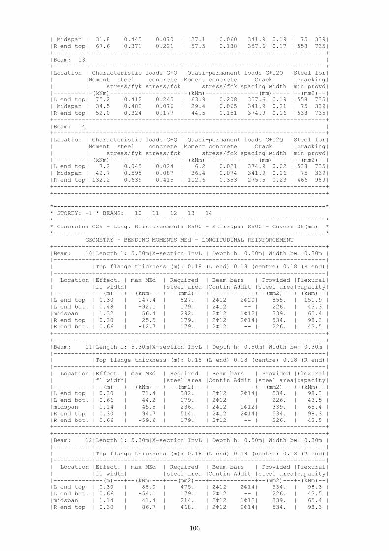
106
| Midspan | 31.8 0.445 0.070 | 27.1 0.060 341.9 0.19 | 75 339|
|R end top| 67.6 0.371 0.221 | 57.5 0.188 357.6 0.17 | 558 735|
+---------+--------------------------+------------------------------+---------+
|Beam: 13 |
+---------+--------------------------+------------------------------+---------+
|Location | Characteristic loads G+Q | Quasi-permanent loads G+ψ2Q |Steel for|
| |Moment steel concrete |Moment concrete Crack | cracking|
| | stress/fyk stress/fck| stress/fck spacing width |min provd|
|---------+-(kNm)--------------------+-(kNm)---------------(mm)-----+--(mm2)--|
|L end top| 75.2 0.412 0.245 | 63.9 0.208 357.6 0.19 | 558 735|
| Midspan | 34.5 0.482 0.076 | 29.4 0.065 341.9 0.21 | 75 339|
|R end top| 52.0 0.324 0.177 | 44.5 0.151 374.9 0.16 | 538 735|
+---------+--------------------------+------------------------------+---------+
|Beam: 14 |
+---------+--------------------------+------------------------------+---------+
|Location | Characteristic loads G+Q | Quasi-permanent loads G+ψ2Q |Steel for|
| |Moment steel concrete |Moment concrete Crack | cracking|
| | stress/fyk stress/fck| stress/fck spacing width |min provd|
|---------+-(kNm)--------------------+-(kNm)---------------(mm)-----+--(mm2)--|
|L end top| 7.2 0.045 0.024 | 6.2 0.021 374.9 0.02 | 538 735|
| Midspan | 42.7 0.595 0.087 | 36.4 0.074 341.9 0.26 | 75 339|
|R end top| 132.2 0.639 0.415 | 112.6 0.353 275.5 0.23 | 466 989|
+---------+--------------------------+------------------------------+---------+
+-----------------------------------------------------------------------------+
*-----------------------------------------------------------------------------*
* STOREY: -1 * BEAMS: 10 11 12 13 14
*-----------------------------------------------------------------------------*
* Concrete: C25 - Long. Reinforcement: S500 - Stirrups: S500 - Cover: 35(mm) *
*-----------------------------------------------------------------------------*
GEOMETRY - BENDING MOMENTS MEd - LONGITUDINAL REINFORCEMENT
+-----------------------------------------------------------------------------+
|Beam: 10|Length l: 5.50m|X-section InvL | Depth h: 0.50m| Width bw: 0.30m |
|-----------+-----------------------------------------------------------------|
| |Top flange thickness (m): 0.18 (L end) 0.18 (centre) 0.18 (R end)|
|-----------+-----------------------------------------------------------------|
| Location |Effect. | max MEd | Required | Beam bars | Provided |Flexural|
| |fl width| |steel area |Contin Addit |steel area|capacity|
|-----------+--(m)---+--(kNm)---+---(mm2)---+-------------+--(mm2)---+-(kNm)--|
|L end top | 0.30 | 147.4 | 827. | 2Φ12 2Φ20| 855. | 151.9 |
|L end bot. | 0.48 | -92.1 | 179. | 2Φ12 -- | 226. | 43.3 |
|midspan | 1.32 | 56.4 | 292. | 2Φ12 1Φ12| 339. | 65.4 |
|R end top | 0.30 | 25.5 | 179. | 2Φ12 2Φ14| 534. | 98.3 |
|R end bot. | 0.66 | -12.7 | 179. | 2Φ12 -- | 226. | 43.5 |
+-----------------------------------------------------------------------------+
+-----------------------------------------------------------------------------+
|Beam: 11|Length l: 5.30m|X-section InvL | Depth h: 0.50m| Width bw: 0.30m |
|-----------+-----------------------------------------------------------------|
| |Top flange thickness (m): 0.18 (L end) 0.18 (centre) 0.18 (R end)|
|-----------+-----------------------------------------------------------------|
| Location |Effect. | max MEd | Required | Beam bars | Provided |Flexural|
| |fl width| |steel area |Contin Addit |steel area|capacity|
|-----------+--(m)---+--(kNm)---+---(mm2)---+-------------+--(mm2)---+-(kNm)--|
|L end top | 0.30 | 71.4 | 382. | 2Φ12 2Φ14| 534. | 98.3 |
|L end bot. | 0.66 | -44.2 | 179. | 2Φ12 -- | 226. | 43.5 |
|midspan | 1.14 | 45.5 | 236. | 2Φ12 1Φ12| 339. | 65.4 |
|R end top | 0.30 | 94.7 | 514. | 2Φ12 2Φ14| 534. | 98.3 |
|R end bot. | 0.66 | -59.6 | 179. | 2Φ12 -- | 226. | 43.5 |
+-----------------------------------------------------------------------------+
+-----------------------------------------------------------------------------+
|Beam: 12|Length l: 5.30m|X-section InvL | Depth h: 0.50m| Width bw: 0.30m |
|-----------+-----------------------------------------------------------------|
| |Top flange thickness (m): 0.18 (L end) 0.18 (centre) 0.18 (R end)|
|-----------+-----------------------------------------------------------------|
| Location |Effect. | max MEd | Required | Beam bars | Provided |Flexural|
| |fl width| |steel area |Contin Addit |steel area|capacity|
|-----------+--(m)---+--(kNm)---+---(mm2)---+-------------+--(mm2)---+-(kNm)--|
|L end top | 0.30 | 88.0 | 475. | 2Φ12 2Φ14| 534. | 98.3 |
|L end bot. | 0.66 | -54.1 | 179. | 2Φ12 -- | 226. | 43.5 |
|midspan | 1.14 | 41.4 | 214. | 2Φ12 1Φ12| 339. | 65.4 |
|R end top | 0.30 | 86.7 | 468. | 2Φ12 2Φ14| 534. | 98.3 |
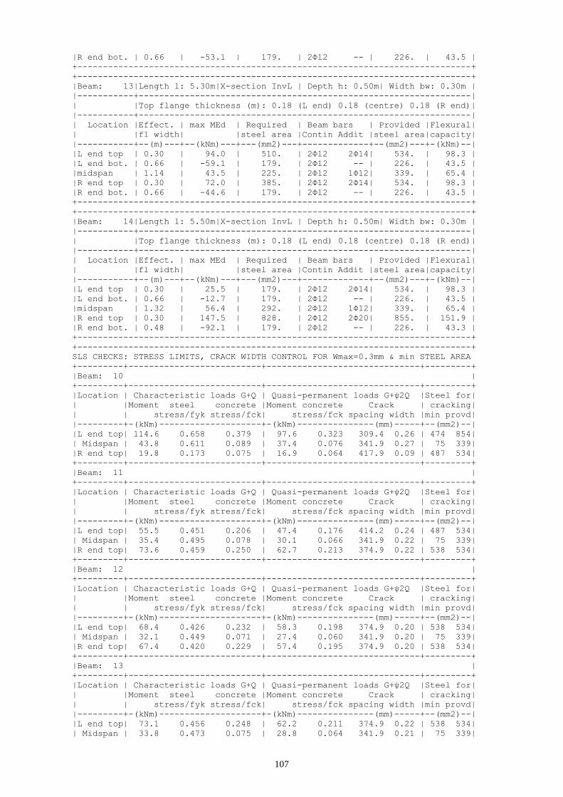
107
|R end bot. | 0.66 | -53.1 | 179. | 2Φ12 -- | 226. | 43.5 |
+-----------------------------------------------------------------------------+
+-----------------------------------------------------------------------------+
|Beam: 13|Length l: 5.30m|X-section InvL | Depth h: 0.50m| Width bw: 0.30m |
|-----------+-----------------------------------------------------------------|
| |Top flange thickness (m): 0.18 (L end) 0.18 (centre) 0.18 (R end)|
|-----------+-----------------------------------------------------------------|
| Location |Effect. | max MEd | Required | Beam bars | Provided |Flexural|
| |fl width| |steel area |Contin Addit |steel area|capacity|
|-----------+--(m)---+--(kNm)---+---(mm2)---+-------------+--(mm2)---+-(kNm)--|
|L end top | 0.30 | 94.0 | 510. | 2Φ12 2Φ14| 534. | 98.3 |
|L end bot. | 0.66 | -59.1 | 179. | 2Φ12 -- | 226. | 43.5 |
|midspan | 1.14 | 43.5 | 225. | 2Φ12 1Φ12| 339. | 65.4 |
|R end top | 0.30 | 72.0 | 385. | 2Φ12 2Φ14| 534. | 98.3 |
|R end bot. | 0.66 | -44.6 | 179. | 2Φ12 -- | 226. | 43.5 |
+-----------------------------------------------------------------------------+
+-----------------------------------------------------------------------------+
|Beam: 14|Length l: 5.50m|X-section InvL | Depth h: 0.50m| Width bw: 0.30m |
|-----------+-----------------------------------------------------------------|
| |Top flange thickness (m): 0.18 (L end) 0.18 (centre) 0.18 (R end)|
|-----------+-----------------------------------------------------------------|
| Location |Effect. | max MEd | Required | Beam bars | Provided |Flexural|
| |fl width| |steel area |Contin Addit |steel area|capacity|
|-----------+--(m)---+--(kNm)---+---(mm2)---+-------------+--(mm2)---+-(kNm)--|
|L end top | 0.30 | 25.5 | 179. | 2Φ12 2Φ14| 534. | 98.3 |
|L end bot. | 0.66 | -12.7 | 179. | 2Φ12 -- | 226. | 43.5 |
|midspan | 1.32 | 56.4 | 292. | 2Φ12 1Φ12| 339. | 65.4 |
|R end top | 0.30 | 147.5 | 828. | 2Φ12 2Φ20| 855. | 151.9 |
|R end bot. | 0.48 | -92.1 | 179. | 2Φ12 -- | 226. | 43.3 |
+-----------------------------------------------------------------------------+
+-----------------------------------------------------------------------------+
SLS CHECKS: STRESS LIMITS, CRACK WIDTH CONTROL FOR Wmax=0.3mm & min STEEL AREA
+---------+--------------------------+------------------------------+---------+
|Beam: 10 |
+---------+--------------------------+------------------------------+---------+
|Location | Characteristic loads G+Q | Quasi-permanent loads G+ψ2Q |Steel for|
| |Moment steel concrete |Moment concrete Crack | cracking|
| | stress/fyk stress/fck| stress/fck spacing width |min provd|
|---------+-(kNm)--------------------+-(kNm)---------------(mm)-----+--(mm2)--|
|L end top| 114.6 0.658 0.379 | 97.6 0.323 309.4 0.26 | 474 854|
| Midspan | 43.8 0.611 0.089 | 37.4 0.076 341.9 0.27 | 75 339|
|R end top| 19.8 0.173 0.075 | 16.9 0.064 417.9 0.09 | 487 534|
+---------+--------------------------+------------------------------+---------+
|Beam: 11 |
+---------+--------------------------+------------------------------+---------+
|Location | Characteristic loads G+Q | Quasi-permanent loads G+ψ2Q |Steel for|
| |Moment steel concrete |Moment concrete Crack | cracking|
| | stress/fyk stress/fck| stress/fck spacing width |min provd|
|---------+-(kNm)--------------------+-(kNm)---------------(mm)-----+--(mm2)--|
|L end top| 55.5 0.451 0.206 | 47.4 0.176 414.2 0.24 | 487 534|
| Midspan | 35.4 0.495 0.078 | 30.1 0.066 341.9 0.22 | 75 339|
|R end top| 73.6 0.459 0.250 | 62.7 0.213 374.9 0.22 | 538 534|
+---------+--------------------------+------------------------------+---------+
|Beam: 12 |
+---------+--------------------------+------------------------------+---------+
|Location | Characteristic loads G+Q | Quasi-permanent loads G+ψ2Q |Steel for|
| |Moment steel concrete |Moment concrete Crack | cracking|
| | stress/fyk stress/fck| stress/fck spacing width |min provd|
|---------+-(kNm)--------------------+-(kNm)---------------(mm)-----+--(mm2)--|
|L end top| 68.4 0.426 0.232 | 58.3 0.198 374.9 0.20 | 538 534|
| Midspan | 32.1 0.449 0.071 | 27.4 0.060 341.9 0.20 | 75 339|
|R end top| 67.4 0.420 0.229 | 57.4 0.195 374.9 0.20 | 538 534|
+---------+--------------------------+------------------------------+---------+
|Beam: 13 |
+---------+--------------------------+------------------------------+---------+
|Location | Characteristic loads G+Q | Quasi-permanent loads G+ψ2Q |Steel for|
| |Moment steel concrete |Moment concrete Crack | cracking|
| | stress/fyk stress/fck| stress/fck spacing width |min provd|
|---------+-(kNm)--------------------+-(kNm)---------------(mm)-----+--(mm2)--|
|L end top| 73.1 0.456 0.248 | 62.2 0.211 374.9 0.22 | 538 534|
| Midspan | 33.8 0.473 0.075 | 28.8 0.064 341.9 0.21 | 75 339|
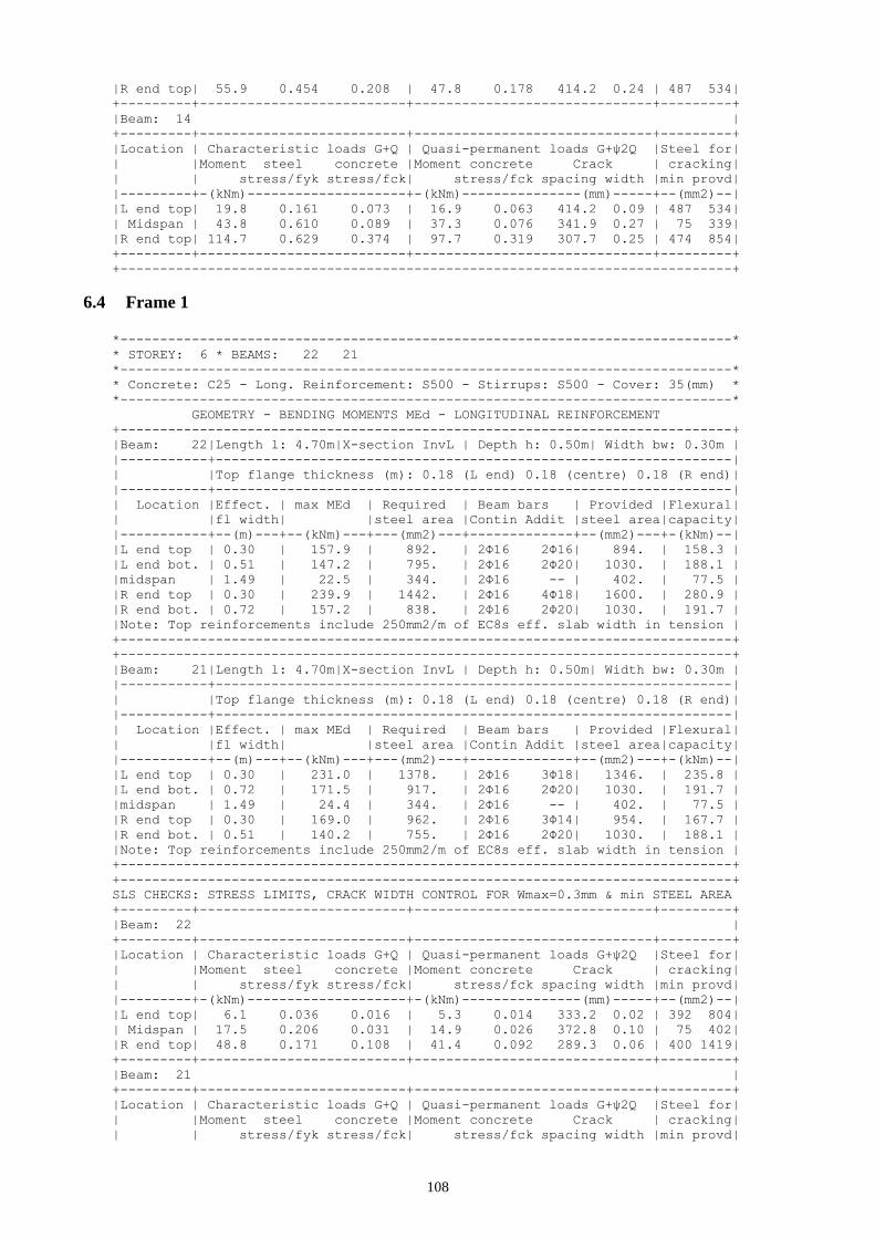
108
|R end top| 55.9 0.454 0.208 | 47.8 0.178 414.2 0.24 | 487 534|
+---------+--------------------------+------------------------------+---------+
|Beam: 14 |
+---------+--------------------------+------------------------------+---------+
|Location | Characteristic loads G+Q | Quasi-permanent loads G+ψ2Q |Steel for|
| |Moment steel concrete |Moment concrete Crack | cracking|
| | stress/fyk stress/fck| stress/fck spacing width |min provd|
|---------+-(kNm)--------------------+-(kNm)---------------(mm)-----+--(mm2)--|
|L end top| 19.8 0.161 0.073 | 16.9 0.063 414.2 0.09 | 487 534|
| Midspan | 43.8 0.610 0.089 | 37.3 0.076 341.9 0.27 | 75 339|
|R end top| 114.7 0.629 0.374 | 97.7 0.319 307.7 0.25 | 474 854|
+---------+--------------------------+------------------------------+---------+
+-----------------------------------------------------------------------------+
6.4 Frame 1
*-----------------------------------------------------------------------------*
* STOREY: 6 * BEAMS: 22 21
*-----------------------------------------------------------------------------*
* Concrete: C25 - Long. Reinforcement: S500 - Stirrups: S500 - Cover: 35(mm) *
*-----------------------------------------------------------------------------*
GEOMETRY - BENDING MOMENTS MEd - LONGITUDINAL REINFORCEMENT
+-----------------------------------------------------------------------------+
|Beam: 22|Length l: 4.70m|X-section InvL | Depth h: 0.50m| Width bw: 0.30m |
|-----------+-----------------------------------------------------------------|
| |Top flange thickness (m): 0.18 (L end) 0.18 (centre) 0.18 (R end)|
|-----------+-----------------------------------------------------------------|
| Location |Effect. | max MEd | Required | Beam bars | Provided |Flexural|
| |fl width| |steel area |Contin Addit |steel area|capacity|
|-----------+--(m)---+--(kNm)---+---(mm2)---+-------------+--(mm2)---+-(kNm)--|
|L end top | 0.30 | 157.9 | 892. | 2Φ16 2Φ16| 894. | 158.3 |
|L end bot. | 0.51 | 147.2 | 795. | 2Φ16 2Φ20| 1030. | 188.1 |
|midspan | 1.49 | 22.5 | 344. | 2Φ16 -- | 402. | 77.5 |
|R end top | 0.30 | 239.9 | 1442. | 2Φ16 4Φ18| 1600. | 280.9 |
|R end bot. | 0.72 | 157.2 | 838. | 2Φ16 2Φ20| 1030. | 191.7 |
|Note: Top reinforcements include 250mm2/m of EC8s eff. slab width in tension |
+-----------------------------------------------------------------------------+
+-----------------------------------------------------------------------------+
|Beam: 21|Length l: 4.70m|X-section InvL | Depth h: 0.50m| Width bw: 0.30m |
|-----------+-----------------------------------------------------------------|
| |Top flange thickness (m): 0.18 (L end) 0.18 (centre) 0.18 (R end)|
|-----------+-----------------------------------------------------------------|
| Location |Effect. | max MEd | Required | Beam bars | Provided |Flexural|
| |fl width| |steel area |Contin Addit |steel area|capacity|
|-----------+--(m)---+--(kNm)---+---(mm2)---+-------------+--(mm2)---+-(kNm)--|
|L end top | 0.30 | 231.0 | 1378. | 2Φ16 3Φ18| 1346. | 235.8 |
|L end bot. | 0.72 | 171.5 | 917. | 2Φ16 2Φ20| 1030. | 191.7 |
|midspan | 1.49 | 24.4 | 344. | 2Φ16 -- | 402. | 77.5 |
|R end top | 0.30 | 169.0 | 962. | 2Φ16 3Φ14| 954. | 167.7 |
|R end bot. | 0.51 | 140.2 | 755. | 2Φ16 2Φ20| 1030. | 188.1 |
|Note: Top reinforcements include 250mm2/m of EC8s eff. slab width in tension |
+-----------------------------------------------------------------------------+
+-----------------------------------------------------------------------------+
SLS CHECKS: STRESS LIMITS, CRACK WIDTH CONTROL FOR Wmax=0.3mm & min STEEL AREA
+---------+--------------------------+------------------------------+---------+
|Beam: 22 |
+---------+--------------------------+------------------------------+---------+
|Location | Characteristic loads G+Q | Quasi-permanent loads G+ψ2Q |Steel for|
| |Moment steel concrete |Moment concrete Crack | cracking|
| | stress/fyk stress/fck| stress/fck spacing width |min provd|
|---------+-(kNm)--------------------+-(kNm)---------------(mm)-----+--(mm2)--|
|L end top| 6.1 0.036 0.016 | 5.3 0.014 333.2 0.02 | 392 804|
| Midspan | 17.5 0.206 0.031 | 14.9 0.026 372.8 0.10 | 75 402|
|R end top| 48.8 0.171 0.108 | 41.4 0.092 289.3 0.06 | 400 1419|
+---------+--------------------------+------------------------------+---------+
|Beam: 21 |
+---------+--------------------------+------------------------------+---------+
|Location | Characteristic loads G+Q | Quasi-permanent loads G+ψ2Q |Steel for|
| |Moment steel concrete |Moment concrete Crack | cracking|
| | stress/fyk stress/fck| stress/fck spacing width |min provd|

109
|---------+-(kNm)--------------------+-(kNm)---------------(mm)-----+--(mm2)--|
|L end top| 35.2 0.142 0.081 | 29.8 0.068 322.9 0.06 | 398 1165|
| Midspan | 19.0 0.223 0.033 | 16.2 0.028 372.8 0.11 | 75 402|
|R end top| 16.7 0.088 0.042 | 14.4 0.036 304.7 0.03 | 370 863|
+---------+--------------------------+------------------------------+---------+
+-----------------------------------------------------------------------------+
JOINT GEOMETRY - SHEAR FORCES - VERIFICATION IN SHEAR
+-----+-----+---------+-------------+-------------+-------------+-------------+
|Joint|Max Φ| J width | J hor. shear| J hor. shear| J hor. steel| J ver. steel|
| | | bj | Vjh | strength | area Ash | area Asv |
+-----+-(mm)+---(m)---+----(kN)-----+----(kN)-----+----(mm2)----+----(mm2)----+
| 1| 26 | 0.30 | 0. | 1205. | 0. | 0. |
| 2| 176 | 0.30 | 0. | 10368. | 0. | 0. |
| 3| 26 | 0.30 | 0. | 1198. | 0. | 0. |
+-----+-----+---------+-------------+-------------+-------------+-------------+
*-----------------------------------------------------------------------------*
* STOREY: 5 * BEAMS: 22 21
*-----------------------------------------------------------------------------*
* Concrete: C25 - Long. Reinforcement: S500 - Stirrups: S500 - Cover: 35(mm) *
*-----------------------------------------------------------------------------*
GEOMETRY - BENDING MOMENTS MEd - LONGITUDINAL REINFORCEMENT
+-----------------------------------------------------------------------------+
|Beam: 22|Length l: 4.70m|X-section InvL | Depth h: 0.50m| Width bw: 0.30m |
|-----------+-----------------------------------------------------------------|
| |Top flange thickness (m): 0.18 (L end) 0.18 (centre) 0.18 (R end)|
|-----------+-----------------------------------------------------------------|
| Location |Effect. | max MEd | Required | Beam bars | Provided |Flexural|
| |fl width| |steel area |Contin Addit |steel area|capacity|
|-----------+--(m)---+--(kNm)---+---(mm2)---+-------------+--(mm2)---+-(kNm)--|
|L end top | 0.30 | 224.9 | 1335. | 2Φ16 4Φ16| 1296. | 222.1 |
|L end bot. | 0.51 | 203.3 | 1120. | 2Φ16 3Φ20| 1345. | 240.7 |
|midspan | 1.49 | 20.7 | 344. | 2Φ16 -- | 402. | 77.5 |
|R end top | 0.30 | 273.3 | 1693. | 2Φ16 5Φ18| 1854. | 323.5 |
|R end bot. | 0.72 | 196.8 | 1059. | 2Φ16 2Φ20| 1030. | 191.7 |
|Note: Top reinforcements include 250mm2/m of EC8s eff. slab width in tension |
+-----------------------------------------------------------------------------+
+-----------------------------------------------------------------------------+
|Beam: 21|Length l: 4.70m|X-section InvL | Depth h: 0.50m| Width bw: 0.30m |
|-----------+-----------------------------------------------------------------|
| |Top flange thickness (m): 0.18 (L end) 0.18 (centre) 0.18 (R end)|
|-----------+-----------------------------------------------------------------|
| Location |Effect. | max MEd | Required | Beam bars | Provided |Flexural|
| |fl width| |steel area |Contin Addit |steel area|capacity|
|-----------+--(m)---+--(kNm)---+---(mm2)---+-------------+--(mm2)---+-(kNm)--|
|L end top | 0.30 | 263.2 | 1615. | 2Φ16 4Φ18| 1600. | 278.7 |
|L end bot. | 0.72 | 213.0 | 1151. | 2Φ16 3Φ20| 1345. | 246.7 |
|midspan | 1.49 | 21.6 | 344. | 2Φ16 -- | 402. | 77.5 |
|R end top | 0.30 | 239.7 | 1441. | 2Φ16 3Φ20| 1435. | 251.9 |
|R end bot. | 0.51 | 194.0 | 1065. | 2Φ16 2Φ20| 1030. | 188.1 |
|Note: Top reinforcements include 250mm2/m of EC8s eff. slab width in tension |
+-----------------------------------------------------------------------------+
+-----------------------------------------------------------------------------+
SLS CHECKS: STRESS LIMITS, CRACK WIDTH CONTROL FOR Wmax=0.3mm & min STEEL AREA
+---------+--------------------------+------------------------------+---------+
|Beam: 22 |
+---------+--------------------------+------------------------------+---------+
|Location | Characteristic loads G+Q | Quasi-permanent loads G+ψ2Q |Steel for|
| |Moment steel concrete |Moment concrete Crack | cracking|
| | stress/fyk stress/fck| stress/fck spacing width |min provd|
|---------+-(kNm)--------------------+-(kNm)---------------(mm)-----+--(mm2)--|
|L end top| 12.4 0.050 0.026 | 10.8 0.023 266.6 0.02 | 392 1206|
| Midspan | 16.1 0.190 0.028 | 13.7 0.024 372.8 0.09 | 75 402|
|R end top| 45.1 0.136 0.096 | 38.2 0.081 264.6 0.05 | 401 1674|
+---------+--------------------------+------------------------------+---------+
|Beam: 21 |
+---------+--------------------------+------------------------------+---------+
|Location | Characteristic loads G+Q | Quasi-permanent loads G+ψ2Q |Steel for|
| |Moment steel concrete |Moment concrete Crack | cracking|
| | stress/fyk stress/fck| stress/fck spacing width |min provd|
|---------+-(kNm)--------------------+-(kNm)---------------(mm)-----+--(mm2)--|

110
|L end top| 29.8 0.100 0.060 | 25.1 0.051 292.0 0.04 | 400 1419|
| Midspan | 16.7 0.197 0.029 | 14.3 0.025 372.8 0.09 | 75 402|
|R end top| 26.5 0.095 0.059 | 22.9 0.051 265.1 0.03 | 419 1344|
+---------+--------------------------+------------------------------+---------+
+-----------------------------------------------------------------------------+
JOINT GEOMETRY - SHEAR FORCES - VERIFICATION IN SHEAR
+-----+-----+---------+-------------+-------------+-------------+-------------+
|Joint|Max Φ| J width | J hor. shear| J hor. shear| J hor. steel| J ver. steel|
| | | bj | Vjh | strength | area Ash | area Asv |
+-----+-(mm)+---(m)---+----(kN)-----+----(kN)-----+----(mm2)----+----(mm2)----+
| 1| 26 | 0.30 | 0. | 1131. | 0. | 0. |
| 2| 180 | 0.30 | 0. | 10176. | 0. | 0. |
| 3| 26 | 0.30 | 0. | 1113. | 0. | 0. |
+-----+-----+---------+-------------+-------------+-------------+-------------+
*-----------------------------------------------------------------------------*
* STOREY: 4 * BEAMS: 22 21
*-----------------------------------------------------------------------------*
* Concrete: C25 - Long. Reinforcement: S500 - Stirrups: S500 - Cover: 35(mm) *
*-----------------------------------------------------------------------------*
GEOMETRY - BENDING MOMENTS MEd - LONGITUDINAL REINFORCEMENT
+-----------------------------------------------------------------------------+
|Beam: 22|Length l: 4.70m|X-section InvL | Depth h: 0.50m| Width bw: 0.30m |
|-----------+-----------------------------------------------------------------|
| |Top flange thickness (m): 0.18 (L end) 0.18 (centre) 0.18 (R end)|
|-----------+-----------------------------------------------------------------|
| Location |Effect. | max MEd | Required | Beam bars | Provided |Flexural|
| |fl width| |steel area |Contin Addit |steel area|capacity|
|-----------+--(m)---+--(kNm)---+---(mm2)---+-------------+--(mm2)---+-(kNm)--|
|L end top | 0.30 | 222.6 | 1319. | 2Φ16 4Φ16| 1296. | 222.1 |
|L end bot. | 0.51 | 200.7 | 1105. | 2Φ16 3Φ20| 1345. | 240.7 |
|midspan | 1.49 | 21.1 | 344. | 2Φ16 -- | 402. | 77.5 |
|R end top | 0.30 | 274.6 | 1703. | 2Φ16 5Φ18| 1854. | 324.4 |
|R end bot. | 0.72 | 199.4 | 1074. | 2Φ16 3Φ20| 1345. | 246.7 |
|Note: Top reinforcements include 250mm2/m of EC8s eff. slab width in tension |
+-----------------------------------------------------------------------------+
+-----------------------------------------------------------------------------+
|Beam: 21|Length l: 4.70m|X-section InvL | Depth h: 0.50m| Width bw: 0.30m |
|-----------+-----------------------------------------------------------------|
| |Top flange thickness (m): 0.18 (L end) 0.18 (centre) 0.18 (R end)|
|-----------+-----------------------------------------------------------------|
| Location |Effect. | max MEd | Required | Beam bars | Provided |Flexural|
| |fl width| |steel area |Contin Addit |steel area|capacity|
|-----------+--(m)---+--(kNm)---+---(mm2)---+-------------+--(mm2)---+-(kNm)--|
|L end top | 0.30 | 265.5 | 1633. | 2Φ16 4Φ18| 1600. | 278.7 |
|L end bot. | 0.72 | 214.5 | 1160. | 2Φ16 3Φ20| 1345. | 246.7 |
|midspan | 1.49 | 22.1 | 344. | 2Φ16 -- | 402. | 77.5 |
|R end top | 0.30 | 236.0 | 1414. | 2Φ16 3Φ20| 1435. | 251.9 |
|R end bot. | 0.51 | 192.5 | 1056. | 2Φ16 2Φ20| 1030. | 188.1 |
|Note: Top reinforcements include 250mm2/m of EC8s eff. slab width in tension |
+-----------------------------------------------------------------------------+
+-----------------------------------------------------------------------------+
SLS CHECKS: STRESS LIMITS, CRACK WIDTH CONTROL FOR Wmax=0.3mm & min STEEL AREA
+---------+--------------------------+------------------------------+---------+
|Beam: 22 |
+---------+--------------------------+------------------------------+---------+
|Location | Characteristic loads G+Q | Quasi-permanent loads G+ψ2Q |Steel for|
| |Moment steel concrete |Moment concrete Crack | cracking|
| | stress/fyk stress/fck| stress/fck spacing width |min provd|
|---------+-(kNm)--------------------+-(kNm)---------------(mm)-----+--(mm2)--|
|L end top| 12.6 0.051 0.027 | 10.9 0.023 266.6 0.02 | 392 1206|
| Midspan | 16.4 0.193 0.029 | 14.0 0.025 372.8 0.09 | 75 402|
|R end top| 44.4 0.133 0.087 | 37.6 0.073 268.0 0.05 | 401 1674|
+---------+--------------------------+------------------------------+---------+
|Beam: 21 |
+---------+--------------------------+------------------------------+---------+
|Location | Characteristic loads G+Q | Quasi-permanent loads G+ψ2Q |Steel for|
| |Moment steel concrete |Moment concrete Crack | cracking|
| | stress/fyk stress/fck| stress/fck spacing width |min provd|
|---------+-(kNm)--------------------+-(kNm)---------------(mm)-----+--(mm2)--|
|L end top| 30.2 0.102 0.061 | 25.5 0.051 292.0 0.04 | 400 1419|

111
| Midspan | 17.2 0.202 0.030 | 14.6 0.026 372.8 0.10 | 75 402|
|R end top| 25.3 0.090 0.056 | 21.8 0.048 265.1 0.03 | 419 1344|
+---------+--------------------------+------------------------------+---------+
+-----------------------------------------------------------------------------+
JOINT GEOMETRY - SHEAR FORCES - VERIFICATION IN SHEAR
+-----+-----+---------+-------------+-------------+-------------+-------------+
|Joint|Max Φ| J width | J hor. shear| J hor. shear| J hor. steel| J ver. steel|
| | | bj | Vjh | strength | area Ash | area Asv |
+-----+-(mm)+---(m)---+----(kN)-----+----(kN)-----+----(mm2)----+----(mm2)----+
| 1| 26 | 0.30 | 0. | 1051. | 0. | 0. |
| 2| 182 | 0.30 | 0. | 9981. | 0. | 0. |
| 3| 26 | 0.30 | 0. | 1021. | 0. | 0. |
+-----+-----+---------+-------------+-------------+-------------+-------------+
*-----------------------------------------------------------------------------*
* STOREY: 3 * BEAMS: 22 21
*-----------------------------------------------------------------------------*
* Concrete: C25 - Long. Reinforcement: S500 - Stirrups: S500 - Cover: 35(mm) *
*-----------------------------------------------------------------------------*
GEOMETRY - BENDING MOMENTS MEd - LONGITUDINAL REINFORCEMENT
+-----------------------------------------------------------------------------+
|Beam: 22|Length l: 4.70m|X-section InvL | Depth h: 0.50m| Width bw: 0.30m |
|-----------+-----------------------------------------------------------------|
| |Top flange thickness (m): 0.18 (L end) 0.18 (centre) 0.18 (R end)|
|-----------+-----------------------------------------------------------------|
| Location |Effect. | max MEd | Required | Beam bars | Provided |Flexural|
| |fl width| |steel area |Contin Addit |steel area|capacity|
|-----------+--(m)---+--(kNm)---+---(mm2)---+-------------+--(mm2)---+-(kNm)--|
|L end top | 0.30 | 222.4 | 1318. | 2Φ16 4Φ16| 1296. | 222.1 |
|L end bot. | 0.51 | 197.2 | 1084. | 2Φ16 3Φ20| 1345. | 240.7 |
|midspan | 1.49 | 21.3 | 344. | 2Φ16 -- | 402. | 77.5 |
|R end top | 0.30 | 269.3 | 1662. | 2Φ16 4Φ18| 1600. | 280.9 |
|R end bot. | 0.72 | 197.8 | 1065. | 2Φ16 2Φ20| 1030. | 191.7 |
|Note: Top reinforcements include 250mm2/m of EC8s eff. slab width in tension |
+-----------------------------------------------------------------------------+
+-----------------------------------------------------------------------------+
|Beam: 21|Length l: 4.70m|X-section InvL | Depth h: 0.50m| Width bw: 0.30m |
|-----------+-----------------------------------------------------------------|
| |Top flange thickness (m): 0.18 (L end) 0.18 (centre) 0.18 (R end)|
|-----------+-----------------------------------------------------------------|
| Location |Effect. | max MEd | Required | Beam bars | Provided |Flexural|
| |fl width| |steel area |Contin Addit |steel area|capacity|
|-----------+--(m)---+--(kNm)---+---(mm2)---+-------------+--(mm2)---+-(kNm)--|
|L end top | 0.30 | 261.6 | 1603. | 2Φ16 4Φ18| 1600. | 278.7 |
|L end bot. | 0.72 | 211.7 | 1144. | 2Φ16 3Φ20| 1345. | 246.7 |
|midspan | 1.49 | 22.1 | 344. | 2Φ16 -- | 402. | 77.5 |
|R end top | 0.30 | 234.9 | 1406. | 2Φ16 3Φ20| 1435. | 251.9 |
|R end bot. | 0.51 | 190.2 | 1043. | 2Φ16 2Φ20| 1030. | 188.1 |
|Note: Top reinforcements include 250mm2/m of EC8s eff. slab width in tension |
+-----------------------------------------------------------------------------+
+-----------------------------------------------------------------------------+
SLS CHECKS: STRESS LIMITS, CRACK WIDTH CONTROL FOR Wmax=0.3mm & min STEEL AREA
+---------+--------------------------+------------------------------+---------+
|Beam: 22 |
+---------+--------------------------+------------------------------+---------+
|Location | Characteristic loads G+Q | Quasi-permanent loads G+ψ2Q |Steel for|
| |Moment steel concrete |Moment concrete Crack | cracking|
| | stress/fyk stress/fck| stress/fck spacing width |min provd|
|---------+-(kNm)--------------------+-(kNm)---------------(mm)-----+--(mm2)--|
|L end top| 14.6 0.059 0.031 | 12.6 0.027 266.6 0.02 | 392 1206|
| Midspan | 16.5 0.194 0.029 | 14.1 0.025 372.8 0.09 | 75 402|
|R end top| 42.2 0.148 0.093 | 35.7 0.079 289.3 0.05 | 400 1419|
+---------+--------------------------+------------------------------+---------+
|Beam: 21 |
+---------+--------------------------+------------------------------+---------+
|Location | Characteristic loads G+Q | Quasi-permanent loads G+ψ2Q |Steel for|
| |Moment steel concrete |Moment concrete Crack | cracking|
| | stress/fyk stress/fck| stress/fck spacing width |min provd|
|---------+-(kNm)--------------------+-(kNm)---------------(mm)-----+--(mm2)--|
|L end top| 29.6 0.100 0.060 | 25.0 0.050 292.0 0.04 | 400 1419|
| Midspan | 17.1 0.202 0.030 | 14.6 0.026 372.8 0.10 | 75 402|

112
|R end top| 25.9 0.092 0.058 | 22.3 0.050 265.1 0.03 | 419 1344|
+---------+--------------------------+------------------------------+---------+
+-----------------------------------------------------------------------------+
JOINT GEOMETRY - SHEAR FORCES - VERIFICATION IN SHEAR
+-----+-----+---------+-------------+-------------+-------------+-------------+
|Joint|Max Φ| J width | J hor. shear| J hor. shear| J hor. steel| J ver. steel|
| | | bj | Vjh | strength | area Ash | area Asv |
+-----+-(mm)+---(m)---+----(kN)-----+----(kN)-----+----(mm2)----+----(mm2)----+
| 1| 26 | 0.30 | 0. | 966. | 0. | 0. |
| 2| 184 | 0.30 | 0. | 9783. | 0. | 0. |
| 3| 26 | 0.30 | 0. | 920. | 0. | 0. |
+-----+-----+---------+-------------+-------------+-------------+-------------+
*-----------------------------------------------------------------------------*
* STOREY: 2 * BEAMS: 22 21
*-----------------------------------------------------------------------------*
* Concrete: C25 - Long. Reinforcement: S500 - Stirrups: S500 - Cover: 35(mm) *
*-----------------------------------------------------------------------------*
GEOMETRY - BENDING MOMENTS MEd - LONGITUDINAL REINFORCEMENT
+-----------------------------------------------------------------------------+
|Beam: 22|Length l: 4.70m|X-section InvL | Depth h: 0.50m| Width bw: 0.30m |
|-----------+-----------------------------------------------------------------|
| |Top flange thickness (m): 0.18 (L end) 0.18 (centre) 0.18 (R end)|
|-----------+-----------------------------------------------------------------|
| Location |Effect. | max MEd | Required | Beam bars | Provided |Flexural|
| |fl width| |steel area |Contin Addit |steel area|capacity|
|-----------+--(m)---+--(kNm)---+---(mm2)---+-------------+--(mm2)---+-(kNm)--|
|L end top | 0.30 | 206.0 | 1205. | 2Φ16 6Φ12| 1171. | 200.9 |
|L end bot. | 0.51 | 175.4 | 956. | 2Φ16 2Φ20| 1030. | 188.1 |
|midspan | 1.49 | 21.3 | 344. | 2Φ16 -- | 402. | 77.5 |
|R end top | 0.30 | 244.2 | 1473. | 2Φ16 5Φ16| 1587. | 278.7 |
|R end bot. | 0.72 | 178.3 | 955. | 2Φ16 2Φ20| 1030. | 191.7 |
|Note: Top reinforcements include 250mm2/m of EC8s eff. slab width in tension |
+-----------------------------------------------------------------------------+
+-----------------------------------------------------------------------------+
|Beam: 21|Length l: 4.70m|X-section InvL | Depth h: 0.50m| Width bw: 0.30m |
|-----------+-----------------------------------------------------------------|
| |Top flange thickness (m): 0.18 (L end) 0.18 (centre) 0.18 (R end)|
|-----------+-----------------------------------------------------------------|
| Location |Effect. | max MEd | Required | Beam bars | Provided |Flexural|
| |fl width| |steel area |Contin Addit |steel area|capacity|
|-----------+--(m)---+--(kNm)---+---(mm2)---+-------------+--(mm2)---+-(kNm)--|
|L end top | 0.30 | 238.8 | 1434. | 2Φ16 4Φ16| 1386. | 243.2 |
|L end bot. | 0.72 | 190.3 | 1023. | 2Φ16 2Φ20| 1030. | 191.7 |
|midspan | 1.49 | 22.0 | 344. | 2Φ16 -- | 402. | 77.5 |
|R end top | 0.30 | 216.7 | 1279. | 2Φ16 3Φ18| 1256. | 219.3 |
|R end bot. | 0.51 | 170.4 | 927. | 2Φ16 2Φ20| 1030. | 188.1 |
|Note: Top reinforcements include 250mm2/m of EC8s eff. slab width in tension |
+-----------------------------------------------------------------------------+
+-----------------------------------------------------------------------------+
SLS CHECKS: STRESS LIMITS, CRACK WIDTH CONTROL FOR Wmax=0.3mm & min STEEL AREA
+---------+--------------------------+------------------------------+---------+
|Beam: 22 |
+---------+--------------------------+------------------------------+---------+
|Location | Characteristic loads G+Q | Quasi-permanent loads G+ψ2Q |Steel for|
| |Moment steel concrete |Moment concrete Crack | cracking|
| | stress/fyk stress/fck| stress/fck spacing width |min provd|
|---------+-(kNm)--------------------+-(kNm)---------------(mm)-----+--(mm2)--|
|L end top| 17.7 0.080 0.042 | 15.3 0.036 256.6 0.03 | 342 1080|
| Midspan | 16.6 0.195 0.029 | 14.1 0.025 372.8 0.09 | 75 402|
|R end top| 38.9 0.138 0.086 | 32.9 0.073 279.3 0.05 | 383 1407|
+---------+--------------------------+------------------------------+---------+
|Beam: 21 |
+---------+--------------------------+------------------------------+---------+
|Location | Characteristic loads G+Q | Quasi-permanent loads G+ψ2Q |Steel for|
| |Moment steel concrete |Moment concrete Crack | cracking|
| | stress/fyk stress/fck| stress/fck spacing width |min provd|
|---------+-(kNm)--------------------+-(kNm)---------------(mm)-----+--(mm2)--|
|L end top| 28.8 0.113 0.066 | 24.3 0.055 303.7 0.04 | 383 1206|
| Midspan | 17.1 0.201 0.030 | 14.6 0.026 372.8 0.10 | 75 402|
|R end top| 26.9 0.109 0.062 | 23.2 0.053 276.7 0.04 | 405 1165|

113
+---------+--------------------------+------------------------------+---------+
+-----------------------------------------------------------------------------+
JOINT GEOMETRY - SHEAR FORCES - VERIFICATION IN SHEAR
+-----+-----+---------+-------------+-------------+-------------+-------------+
|Joint|Max Φ| J width | J hor. shear| J hor. shear| J hor. steel| J ver. steel|
| | | bj | Vjh | strength | area Ash | area Asv |
+-----+-(mm)+---(m)---+----(kN)-----+----(kN)-----+----(mm2)----+----(mm2)----+
| 1| 26 | 0.30 | 0. | 876. | 0. | 0. |
| 2| 184 | 0.30 | 0. | 9583. | 0. | 0. |
| 3| 26 | 0.30 | 0. | 810. | 0. | 0. |
+-----+-----+---------+-------------+-------------+-------------+-------------+
*-----------------------------------------------------------------------------*
* STOREY: 1 * BEAMS: 22 21
*-----------------------------------------------------------------------------*
* Concrete: C25 - Long. Reinforcement: S500 - Stirrups: S500 - Cover: 35(mm) *
*-----------------------------------------------------------------------------*
GEOMETRY - BENDING MOMENTS MEd - LONGITUDINAL REINFORCEMENT
+-----------------------------------------------------------------------------+
|Beam: 22|Length l: 4.70m|X-section InvL | Depth h: 0.50m| Width bw: 0.30m |
|-----------+-----------------------------------------------------------------|
| |Top flange thickness (m): 0.18 (L end) 0.18 (centre) 0.18 (R end)|
|-----------+-----------------------------------------------------------------|
| Location |Effect. | max MEd | Required | Beam bars | Provided |Flexural|
| |fl width| |steel area |Contin Addit |steel area|capacity|
|-----------+--(m)---+--(kNm)---+---(mm2)---+-------------+--(mm2)---+-(kNm)--|
|L end top | 0.30 | 159.1 | 900. | 2Φ16 2Φ16| 894. | 158.3 |
|L end bot. | 0.51 | 127.4 | 683. | 2Φ16 1Φ20| 716. | 133.3 |
|midspan | 1.49 | 22.5 | 344. | 2Φ16 -- | 402. | 77.5 |
|R end top | 0.30 | 190.9 | 1104. | 2Φ16 2Φ18| 1091. | 188.9 |
|R end bot. | 0.72 | 129.2 | 684. | 2Φ16 1Φ20| 716. | 135.1 |
|Note: Top reinforcements include 250mm2/m of EC8s eff. slab width in tension |
+-----------------------------------------------------------------------------+
+-----------------------------------------------------------------------------+
|Beam: 21|Length l: 4.70m|X-section InvL | Depth h: 0.50m| Width bw: 0.30m |
|-----------+-----------------------------------------------------------------|
| |Top flange thickness (m): 0.18 (L end) 0.18 (centre) 0.18 (R end)|
|-----------+-----------------------------------------------------------------|
| Location |Effect. | max MEd | Required | Beam bars | Provided |Flexural|
| |fl width| |steel area |Contin Addit |steel area|capacity|
|-----------+--(m)---+--(kNm)---+---(mm2)---+-------------+--(mm2)---+-(kNm)--|
|L end top | 0.30 | 188.9 | 1091. | 2Φ16 2Φ18| 1091. | 188.9 |
|L end bot. | 0.72 | 138.6 | 736. | 2Φ16 1Φ20| 716. | 135.1 |
|midspan | 1.49 | 22.9 | 344. | 2Φ16 -- | 402. | 77.5 |
|R end top | 0.30 | 167.7 | 954. | 2Φ16 3Φ14| 954. | 167.7 |
|R end bot. | 0.51 | 125.6 | 673. | 2Φ16 1Φ20| 716. | 133.3 |
|Note: Top reinforcements include 250mm2/m of EC8s eff. slab width in tension |
+-----------------------------------------------------------------------------+
+-----------------------------------------------------------------------------+
SLS CHECKS: STRESS LIMITS, CRACK WIDTH CONTROL FOR Wmax=0.3mm & min STEEL AREA
+---------+--------------------------+------------------------------+---------+
|Beam: 22 |
+---------+--------------------------+------------------------------+---------+
|Location | Characteristic loads G+Q | Quasi-permanent loads G+ψ2Q |Steel for|
| |Moment steel concrete |Moment concrete Crack | cracking|
| | stress/fyk stress/fck| stress/fck spacing width |min provd|
|---------+-(kNm)--------------------+-(kNm)---------------(mm)-----+--(mm2)--|
|L end top| 18.4 0.109 0.052 | 15.9 0.045 328.4 0.05 | 392 804|
| Midspan | 17.5 0.206 0.031 | 14.9 0.026 372.8 0.10 | 75 402|
|R end top| 36.5 0.193 0.100 | 30.8 0.084 371.9 0.09 | 396 911|
+---------+--------------------------+------------------------------+---------+
|Beam: 21 |
+---------+--------------------------+------------------------------+---------+
|Location | Characteristic loads G+Q | Quasi-permanent loads G+ψ2Q |Steel for|
| |Moment steel concrete |Moment concrete Crack | cracking|
| | stress/fyk stress/fck| stress/fck spacing width |min provd|
|---------+-(kNm)--------------------+-(kNm)---------------(mm)-----+--(mm2)--|
|L end top| 29.8 0.150 0.080 | 25.2 0.068 369.3 0.07 | 396 911|
| Midspan | 17.8 0.209 0.031 | 15.2 0.027 372.8 0.10 | 75 402|
|R end top| 24.4 0.129 0.067 | 21.1 0.057 300.5 0.05 | 370 863|
+---------+--------------------------+------------------------------+---------+

114
+-----------------------------------------------------------------------------+
JOINT GEOMETRY - SHEAR FORCES - VERIFICATION IN SHEAR
+-----+-----+---------+-------------+-------------+-------------+-------------+
|Joint|Max Φ| J width | J hor. shear| J hor. shear| J hor. steel| J ver. steel|
| | | bj | Vjh | strength | area Ash | area Asv |
+-----+-(mm)+---(m)---+----(kN)-----+----(kN)-----+----(mm2)----+----(mm2)----+
| 1| 26 | 0.30 | 0. | 790. | 0. | 0. |
| 2| 186 | 0.30 | 0. | 9385. | 0. | 0. |
| 3| 26 | 0.30 | 0. | 701. | 0. | 0. |
+-----+-----+---------+-------------+-------------+-------------+-------------+
6.5 Frame 2
*-----------------------------------------------------------------------------*
* STOREY: 6 * BEAMS: 28 27
*-----------------------------------------------------------------------------*
* Concrete: C25 - Long. Reinforcement: S500 - Stirrups: S500 - Cover: 35(mm) *
*-----------------------------------------------------------------------------*
GEOMETRY - BENDING MOMENTS MEd - LONGITUDINAL REINFORCEMENT
+-----------------------------------------------------------------------------+
|Beam: 28|Length l: 6.60m|X-section T | Depth h: 0.50m| Width bw: 0.30m |
|-----------+-----------------------------------------------------------------|
| |Top flange thickness (m): 0.18 (L end) 0.18 (centre) 0.18 (R end)|
|-----------+-----------------------------------------------------------------|
| Location |Effect. | max MEd | Required | Beam bars | Provided |Flexural|
| |fl width| |steel area |Contin Addit |steel area|capacity|
|-----------+--(m)---+--(kNm)---+---(mm2)---+-------------+--(mm2)---+-(kNm)--|
|L end top | 0.30 | 119.6 | 659. | 2Φ14 3Φ12| 927. | 163.5 |
|L end bot. | 0.72 | -9.7 | 344. | 2Φ14 -- | 462. | 88.0 |
|midspan | 2.68 | 116.3 | 602. | 2Φ14 2Φ14| 616. | 118.8 |
|R end top | 0.30 | 148.0 | 831. | 2Φ14 5Φ12| 1283. | 225.7 |
|R end bot. | 1.14 | -18.4 | 415. | 2Φ14 -- | 462. | 88.7 |
|Note: Top reinforcements include 250mm2/m of EC8s eff. slab width in tension |
|Note:1. Addit. bot. midspan bars extended: 1Φ14 to L end - 1Φ14 to R end |
| 2. Addit. bot. midspan bars extended to Left end of beam 2: 1Φ14 |
+-----------------------------------------------------------------------------+
+-----------------------------------------------------------------------------+
|Beam: 27|Length l: 6.60m|X-section T | Depth h: 0.50m| Width bw: 0.30m |
|-----------+-----------------------------------------------------------------|
| |Top flange thickness (m): 0.18 (L end) 0.18 (centre) 0.18 (R end)|
|-----------+-----------------------------------------------------------------|
| Location |Effect. | max MEd | Required | Beam bars | Provided |Flexural|
| |fl width| |steel area |Contin Addit |steel area|capacity|
|-----------+--(m)---+--(kNm)---+---(mm2)---+-------------+--(mm2)---+-(kNm)--|
|L end top | 0.30 | 160.9 | 911. | 2Φ14 5Φ12| 1283. | 225.7 |
|L end bot. | 1.14 | -31.7 | 455. | 2Φ14 -- | 462. | 88.7 |
|midspan | 2.68 | 114.9 | 595. | 2Φ14 2Φ14| 616. | 118.8 |
|R end top | 0.30 | 108.2 | 624. | 2Φ14 2Φ12| 814. | 145.3 |
|R end bot. | 0.72 | 1.4 | 344. | 2Φ14 -- | 462. | 88.0 |
|Note: Top reinforcements include 250mm2/m of EC8s eff. slab width in tension |
|Note:1. Addit. bot. midspan bars extended: 1Φ14 to Right end. |
| 2. Addit. bot. midspan bars of beam 1 ext. to L end of beam 2: 1Φ14|
+-----------------------------------------------------------------------------+
+-----------------------------------------------------------------------------+
SLS CHECKS: STRESS LIMITS, CRACK WIDTH CONTROL FOR Wmax=0.3mm & min STEEL AREA
+---------+--------------------------+------------------------------+---------+
|Beam: 28 |
+---------+--------------------------+------------------------------+---------+
|Location | Characteristic loads G+Q | Quasi-permanent loads G+ψ2Q |Steel for|
| |Moment steel concrete |Moment concrete Crack | cracking|
| | stress/fyk stress/fck| stress/fck spacing width |min provd|
|---------+-(kNm)--------------------+-(kNm)---------------(mm)-----+--(mm2)--|
|L end top| 75.7 0.512 0.243 | 64.6 0.207 382.3 0.25 | 218 647|
| Midspan | 90.4 0.691 0.096 | 77.1 0.082 283.2 0.25 | 75 615|
|R end top| 97.8 0.514 0.289 | 83.2 0.246 387.4 0.25 | 310 873|
+---------+--------------------------+------------------------------+---------+
|Beam: 27 |
+---------+--------------------------+------------------------------+---------+
|Location | Characteristic loads G+Q | Quasi-permanent loads G+ψ2Q |Steel for|
| |Moment steel concrete |Moment concrete Crack | cracking|

115
| | stress/fyk stress/fck| stress/fck spacing width |min provd|
|---------+-(kNm)--------------------+-(kNm)---------------(mm)-----+--(mm2)--|
|L end top| 113.1 0.540 0.325 | 96.3 0.277 381.9 0.26 | 310 873|
| Midspan | 89.3 0.683 0.095 | 76.2 0.081 283.2 0.25 | 75 615|
|R end top| 62.5 0.427 0.201 | 53.4 0.172 429.1 0.23 | 222 534|
+---------+--------------------------+------------------------------+---------+
+-----------------------------------------------------------------------------+
JOINT GEOMETRY - SHEAR FORCES - VERIFICATION IN SHEAR
+-----+-----+---------+-------------+-------------+-------------+-------------+
|Joint|Max Φ| J width | J hor. shear| J hor. shear| J hor. steel| J ver. steel|
| | | bj | Vjh | strength | area Ash | area Asv |
+-----+-(mm)+---(m)---+----(kN)-----+----(kN)-----+----(mm2)----+----(mm2)----+
| 1| 14 | 0.45 | 0. | 895. | 0. | 0. |
| 2| 22 | 0.50 | 0. | 2022. | 0. | 0. |
| 3| 14 | 0.45 | 0. | 899. | 0. | 0. |
+-----+-----+---------+-------------+-------------+-------------+-------------+
*-----------------------------------------------------------------------------*
* STOREY: 5 * BEAMS: 28 27
*-----------------------------------------------------------------------------*
* Concrete: C25 - Long. Reinforcement: S500 - Stirrups: S500 - Cover: 35(mm) *
*-----------------------------------------------------------------------------*
GEOMETRY - BENDING MOMENTS MEd - LONGITUDINAL REINFORCEMENT
+-----------------------------------------------------------------------------+
|Beam: 28|Length l: 6.60m|X-section T | Depth h: 0.50m| Width bw: 0.30m |
|-----------+-----------------------------------------------------------------|
| |Top flange thickness (m): 0.18 (L end) 0.18 (centre) 0.18 (R end)|
|-----------+-----------------------------------------------------------------|
| Location |Effect. | max MEd | Required | Beam bars | Provided |Flexural|
| |fl width| |steel area |Contin Addit |steel area|capacity|
|-----------+--(m)---+--(kNm)---+---(mm2)---+-------------+--(mm2)---+-(kNm)--|
|L end top | 0.30 | 202.5 | 1182. | 2Φ14 4Φ14| 1204. | 213.0 |
|L end bot. | 0.72 | -12.2 | 591. | 2Φ14 -- | 616. | 116.6 |
|midspan | 2.68 | 101.7 | 526. | 2Φ14 2Φ14| 616. | 118.8 |
|R end top | 0.30 | 164.5 | 934. | 2Φ14 2Φ16| 1120. | 193.3 |
|R end bot. | 1.14 | 44.8 | 467. | 2Φ14 -- | 462. | 88.7 |
|Note: Top reinforcements include 250mm2/m of EC8s eff. slab width in tension |
|Note:1. Addit. bot. midspan bars extended: 2Φ14 to L end - 1Φ14 to R end |
| 2. Addit. bot. midspan bars extended to Left end of beam 2: 1Φ14 |
+-----------------------------------------------------------------------------+
+-----------------------------------------------------------------------------+
|Beam: 27|Length l: 6.60m|X-section T | Depth h: 0.50m| Width bw: 0.30m |
|-----------+-----------------------------------------------------------------|
| |Top flange thickness (m): 0.18 (L end) 0.18 (centre) 0.18 (R end)|
|-----------+-----------------------------------------------------------------|
| Location |Effect. | max MEd | Required | Beam bars | Provided |Flexural|
| |fl width| |steel area |Contin Addit |steel area|capacity|
|-----------+--(m)---+--(kNm)---+---(mm2)---+-------------+--(mm2)---+-(kNm)--|
|L end top | 0.30 | 185.0 | 1065. | 2Φ14 3Φ16| 1321. | 232.9 |
|L end bot. | 1.14 | 23.8 | 533. | 2Φ14 -- | 616. | 117.7 |
|midspan | 2.68 | 100.3 | 519. | 2Φ14 2Φ14| 616. | 118.8 |
|R end top | 0.30 | 183.4 | 1055. | 2Φ14 3Φ14| 1050. | 182.6 |
|R end bot. | 0.72 | 6.5 | 528. | 2Φ14 -- | 616. | 116.6 |
|Note: Top reinforcements include 250mm2/m of EC8s eff. slab width in tension |
|Note:1. Addit. bot. midspan bars extended: 1Φ14 to L end - 2Φ14 to R end |
| 2. Addit. bot. midspan bars of beam 1 ext. to L end of beam 2: 1Φ14|
+-----------------------------------------------------------------------------+
+-----------------------------------------------------------------------------+
SLS CHECKS: STRESS LIMITS, CRACK WIDTH CONTROL FOR Wmax=0.3mm & min STEEL AREA
+---------+--------------------------+------------------------------+---------+
|Beam: 28 |
+---------+--------------------------+------------------------------+---------+
|Location | Characteristic loads G+Q | Quasi-permanent loads G+ψ2Q |Steel for|
| |Moment steel concrete |Moment concrete Crack | cracking|
| | stress/fyk stress/fck| stress/fck spacing width |min provd|
|---------+-(kNm)--------------------+-(kNm)---------------(mm)-----+--(mm2)--|
|L end top| 125.8 0.628 0.348 | 107.4 0.297 324.8 0.26 | 239 923|
| Midspan | 79.0 0.605 0.084 | 67.4 0.071 283.2 0.22 | 75 615|
|R end top| 70.4 0.441 0.220 | 59.9 0.187 498.3 0.28 | 380 709|
+---------+--------------------------+------------------------------+---------+
|Beam: 27 |

116
+---------+--------------------------+------------------------------+---------+
|Location | Characteristic loads G+Q | Quasi-permanent loads G+ψ2Q |Steel for|
| |Moment steel concrete |Moment concrete Crack | cracking|
| | stress/fyk stress/fck| stress/fck spacing width |min provd|
|---------+-(kNm)--------------------+-(kNm)---------------(mm)-----+--(mm2)--|
|L end top| 94.8 0.436 0.256 | 80.6 0.218 423.7 0.24 | 386 911|
| Midspan | 77.9 0.596 0.083 | 66.4 0.070 283.2 0.22 | 75 615|
|R end top| 103.6 0.542 0.291 | 88.5 0.248 358.5 0.25 | 239 769|
+---------+--------------------------+------------------------------+---------+
+-----------------------------------------------------------------------------+
JOINT GEOMETRY - SHEAR FORCES - VERIFICATION IN SHEAR
+-----+-----+---------+-------------+-------------+-------------+-------------+
|Joint|Max Φ| J width | J hor. shear| J hor. shear| J hor. steel| J ver. steel|
| | | bj | Vjh | strength | area Ash | area Asv |
+-----+-(mm)+---(m)---+----(kN)-----+----(kN)-----+----(mm2)----+----(mm2)----+
| 1| 14 | 0.45 | 0. | 832. | 0. | 0. |
| 2| 24 | 0.50 | 0. | 1852. | 0. | 0. |
| 3| 14 | 0.45 | 0. | 842. | 0. | 0. |
+-----+-----+---------+-------------+-------------+-------------+-------------+
*-----------------------------------------------------------------------------*
* STOREY: 4 * BEAMS: 28 27
*-----------------------------------------------------------------------------*
* Concrete: C25 - Long. Reinforcement: S500 - Stirrups: S500 - Cover: 35(mm) *
*-----------------------------------------------------------------------------*
GEOMETRY - BENDING MOMENTS MEd - LONGITUDINAL REINFORCEMENT
+-----------------------------------------------------------------------------+
|Beam: 28|Length l: 6.60m|X-section T | Depth h: 0.50m| Width bw: 0.30m |
|-----------+-----------------------------------------------------------------|
| |Top flange thickness (m): 0.18 (L end) 0.18 (centre) 0.18 (R end)|
|-----------+-----------------------------------------------------------------|
| Location |Effect. | max MEd | Required | Beam bars | Provided |Flexural|
| |fl width| |steel area |Contin Addit |steel area|capacity|
|-----------+--(m)---+--(kNm)---+---(mm2)---+-------------+--(mm2)---+-(kNm)--|
|L end top | 0.30 | 195.9 | 1138. | 2Φ14 5Φ12| 1153. | 198.3 |
|L end bot. | 0.72 | -7.8 | 569. | 2Φ14 -- | 616. | 116.6 |
|midspan | 2.68 | 103.2 | 534. | 2Φ14 2Φ14| 616. | 118.8 |
|R end top | 0.30 | 166.9 | 949. | 2Φ14 2Φ16| 1120. | 193.3 |
|R end bot. | 1.14 | 40.3 | 474. | 2Φ14 -- | 462. | 88.7 |
|Note: Top reinforcements include 250mm2/m of EC8s eff. slab width in tension |
|Note:1. Addit. bot. midspan bars extended: 2Φ14 to L end - 1Φ14 to R end |
| 2. Addit. bot. midspan bars extended to Left end of beam 2: 1Φ14 |
+-----------------------------------------------------------------------------+
+-----------------------------------------------------------------------------+
|Beam: 27|Length l: 6.60m|X-section T | Depth h: 0.50m| Width bw: 0.30m |
|-----------+-----------------------------------------------------------------|
| |Top flange thickness (m): 0.18 (L end) 0.18 (centre) 0.18 (R end)|
|-----------+-----------------------------------------------------------------|
| Location |Effect. | max MEd | Required | Beam bars | Provided |Flexural|
| |fl width| |steel area |Contin Addit |steel area|capacity|
|-----------+--(m)---+--(kNm)---+---(mm2)---+-------------+--(mm2)---+-(kNm)--|
|L end top | 0.30 | 187.1 | 1079. | 2Φ14 3Φ16| 1321. | 232.9 |
|L end bot. | 1.14 | 19.5 | 540. | 2Φ14 -- | 616. | 117.7 |
|midspan | 2.68 | 101.9 | 527. | 2Φ14 2Φ14| 616. | 118.8 |
|R end top | 0.30 | 177.0 | 1013. | 2Φ14 4Φ12| 1040. | 181.1 |
|R end bot. | 0.72 | 10.7 | 507. | 2Φ14 -- | 616. | 116.6 |
|Note: Top reinforcements include 250mm2/m of EC8s eff. slab width in tension |
|Note:1. Addit. bot. midspan bars extended: 1Φ14 to L end - 2Φ14 to R end |
| 2. Addit. bot. midspan bars of beam 1 ext. to L end of beam 2: 1Φ14|
+-----------------------------------------------------------------------------+
+-----------------------------------------------------------------------------+
SLS CHECKS: STRESS LIMITS, CRACK WIDTH CONTROL FOR Wmax=0.3mm & min STEEL AREA
+---------+--------------------------+------------------------------+---------+
|Beam: 28 |
+---------+--------------------------+------------------------------+---------+
|Location | Characteristic loads G+Q | Quasi-permanent loads G+ψ2Q |Steel for|
| |Moment steel concrete |Moment concrete Crack | cracking|
| | stress/fyk stress/fck| stress/fck spacing width |min provd|
|---------+-(kNm)--------------------+-(kNm)---------------(mm)-----+--(mm2)--|
|L end top| 119.4 0.625 0.335 | 101.9 0.286 317.6 0.25 | 214 873|
| Midspan | 80.2 0.614 0.085 | 68.4 0.073 283.2 0.22 | 75 615|

117
|R end top| 74.5 0.466 0.233 | 63.3 0.198 498.3 0.30 | 380 709|
+---------+--------------------------+------------------------------+---------+
|Beam: 27 |
+---------+--------------------------+------------------------------+---------+
|Location | Characteristic loads G+Q | Quasi-permanent loads G+ψ2Q |Steel for|
| |Moment steel concrete |Moment concrete Crack | cracking|
| | stress/fyk stress/fck| stress/fck spacing width |min provd|
|---------+-(kNm)--------------------+-(kNm)---------------(mm)-----+--(mm2)--|
|L end top| 98.5 0.453 0.266 | 83.8 0.226 423.7 0.24 | 386 911|
| Midspan | 79.2 0.606 0.084 | 67.5 0.072 283.2 0.22 | 75 615|
|R end top| 97.4 0.514 0.274 | 83.2 0.234 341.9 0.23 | 215 760|
+---------+--------------------------+------------------------------+---------+
+-----------------------------------------------------------------------------+
JOINT GEOMETRY - SHEAR FORCES - VERIFICATION IN SHEAR
+-----+-----+---------+-------------+-------------+-------------+-------------+
|Joint|Max Φ| J width | J hor. shear| J hor. shear| J hor. steel| J ver. steel|
| | | bj | Vjh | strength | area Ash | area Asv |
+-----+-(mm)+---(m)---+----(kN)-----+----(kN)-----+----(mm2)----+----(mm2)----+
| 1| 14 | 0.45 | 0. | 763. | 0. | 0. |
| 2| 24 | 0.50 | 0. | 1659. | 0. | 0. |
| 3| 14 | 0.45 | 0. | 781. | 0. | 0. |
+-----+-----+---------+-------------+-------------+-------------+-------------+
*-----------------------------------------------------------------------------*
* STOREY: 3 * BEAMS: 28 27
*-----------------------------------------------------------------------------*
* Concrete: C25 - Long. Reinforcement: S500 - Stirrups: S500 - Cover: 35(mm) *
*-----------------------------------------------------------------------------*
GEOMETRY - BENDING MOMENTS MEd - LONGITUDINAL REINFORCEMENT
+-----------------------------------------------------------------------------+
|Beam: 28|Length l: 6.60m|X-section T | Depth h: 0.50m| Width bw: 0.30m |
|-----------+-----------------------------------------------------------------|
| |Top flange thickness (m): 0.18 (L end) 0.18 (centre) 0.18 (R end)|
|-----------+-----------------------------------------------------------------|
| Location |Effect. | max MEd | Required | Beam bars | Provided |Flexural|
| |fl width| |steel area |Contin Addit |steel area|capacity|
|-----------+--(m)---+--(kNm)---+---(mm2)---+-------------+--(mm2)---+-(kNm)--|
|L end top | 0.30 | 194.3 | 1127. | 2Φ14 5Φ12| 1153. | 198.3 |
|L end bot. | 0.72 | -9.1 | 563. | 2Φ14 -- | 616. | 116.6 |
|midspan | 2.68 | 102.9 | 533. | 2Φ14 2Φ14| 616. | 118.8 |
|R end top | 0.30 | 165.9 | 943. | 2Φ14 2Φ16| 1120. | 193.3 |
|R end bot. | 1.14 | 38.2 | 471. | 2Φ14 -- | 462. | 88.7 |
|Note: Top reinforcements include 250mm2/m of EC8s eff. slab width in tension |
|Note:1. Addit. bot. midspan bars extended: 2Φ14 to L end - 1Φ14 to R end |
| 2. Addit. bot. midspan bars extended to Left end of beam 2: 1Φ14 |
+-----------------------------------------------------------------------------+
+-----------------------------------------------------------------------------+
|Beam: 27|Length l: 6.60m|X-section T | Depth h: 0.50m| Width bw: 0.30m |
|-----------+-----------------------------------------------------------------|
| |Top flange thickness (m): 0.18 (L end) 0.18 (centre) 0.18 (R end)|
|-----------+-----------------------------------------------------------------|
| Location |Effect. | max MEd | Required | Beam bars | Provided |Flexural|
| |fl width| |steel area |Contin Addit |steel area|capacity|
|-----------+--(m)---+--(kNm)---+---(mm2)---+-------------+--(mm2)---+-(kNm)--|
|L end top | 0.30 | 187.2 | 1080. | 2Φ14 3Φ16| 1321. | 232.9 |
|L end bot. | 1.14 | 16.3 | 540. | 2Φ14 -- | 616. | 117.7 |
|midspan | 2.68 | 101.4 | 525. | 2Φ14 2Φ14| 616. | 118.8 |
|R end top | 0.30 | 174.5 | 997. | 2Φ14 4Φ12| 1040. | 181.1 |
|R end bot. | 0.72 | 10.3 | 499. | 2Φ14 -- | 616. | 116.6 |
|Note: Top reinforcements include 250mm2/m of EC8s eff. slab width in tension |
|Note:1. Addit. bot. midspan bars extended: 1Φ14 to L end - 2Φ14 to R end |
| 2. Addit. bot. midspan bars of beam 1 ext. to L end of beam 2: 1Φ14|
+-----------------------------------------------------------------------------+
+-----------------------------------------------------------------------------+
SLS CHECKS: STRESS LIMITS, CRACK WIDTH CONTROL FOR Wmax=0.3mm & min STEEL AREA
+---------+--------------------------+------------------------------+---------+
|Beam: 28 |
+---------+--------------------------+------------------------------+---------+
|Location | Characteristic loads G+Q | Quasi-permanent loads G+ψ2Q |Steel for|
| |Moment steel concrete |Moment concrete Crack | cracking|
| | stress/fyk stress/fck| stress/fck spacing width |min provd|

118
|---------+-(kNm)--------------------+-(kNm)---------------(mm)-----+--(mm2)--|
|L end top| 119.2 0.624 0.335 | 101.7 0.286 317.6 0.25 | 214 873|
| Midspan | 80.0 0.612 0.085 | 68.2 0.072 283.2 0.22 | 75 615|
|R end top| 75.1 0.471 0.235 | 63.9 0.200 498.3 0.30 | 380 709|
+---------+--------------------------+------------------------------+---------+
|Beam: 27 |
+---------+--------------------------+------------------------------+---------+
|Location | Characteristic loads G+Q | Quasi-permanent loads G+ψ2Q |Steel for|
| |Moment steel concrete |Moment concrete Crack | cracking|
| | stress/fyk stress/fck| stress/fck spacing width |min provd|
|---------+-(kNm)--------------------+-(kNm)---------------(mm)-----+--(mm2)--|
|L end top| 100.5 0.462 0.271 | 85.5 0.231 423.7 0.25 | 386 911|
| Midspan | 78.8 0.603 0.084 | 67.2 0.071 283.2 0.22 | 75 615|
|R end top| 96.2 0.508 0.271 | 82.1 0.231 341.9 0.22 | 215 760|
+---------+--------------------------+------------------------------+---------+
+-----------------------------------------------------------------------------+
JOINT GEOMETRY - SHEAR FORCES - VERIFICATION IN SHEAR
+-----+-----+---------+-------------+-------------+-------------+-------------+
|Joint|Max Φ| J width | J hor. shear| J hor. shear| J hor. steel| J ver. steel|
| | | bj | Vjh | strength | area Ash | area Asv |
+-----+-(mm)+---(m)---+----(kN)-----+----(kN)-----+----(mm2)----+----(mm2)----+
| 1| 14 | 0.45 | 0. | 688. | 0. | 0. |
| 2| 26 | 0.50 | 0. | 1439. | 0. | 0. |
| 3| 14 | 0.45 | 0. | 715. | 0. | 0. |
+-----+-----+---------+-------------+-------------+-------------+-------------+
*-----------------------------------------------------------------------------*
* STOREY: 2 * BEAMS: 28 27
*-----------------------------------------------------------------------------*
* Concrete: C25 - Long. Reinforcement: S500 - Stirrups: S500 - Cover: 35(mm) *
*-----------------------------------------------------------------------------*
GEOMETRY - BENDING MOMENTS MEd - LONGITUDINAL REINFORCEMENT
+-----------------------------------------------------------------------------+
|Beam: 28|Length l: 6.60m|X-section T | Depth h: 0.50m| Width bw: 0.30m |
|-----------+-----------------------------------------------------------------|
| |Top flange thickness (m): 0.18 (L end) 0.18 (centre) 0.18 (R end)|
|-----------+-----------------------------------------------------------------|
| Location |Effect. | max MEd | Required | Beam bars | Provided |Flexural|
| |fl width| |steel area |Contin Addit |steel area|capacity|
|-----------+--(m)---+--(kNm)---+---(mm2)---+-------------+--(mm2)---+-(kNm)--|
|L end top | 0.30 | 187.2 | 1080. | 2Φ14 4Φ14| 1204. | 213.0 |
|L end bot. | 0.72 | -18.2 | 540. | 2Φ14 -- | 616. | 116.6 |
|midspan | 2.68 | 101.9 | 528. | 2Φ14 2Φ14| 616. | 118.8 |
|R end top | 0.30 | 157.3 | 888. | 2Φ14 3Φ14| 1180. | 202.2 |
|R end bot. | 1.14 | 29.0 | 444. | 2Φ14 -- | 462. | 88.7 |
|Note: Top reinforcements include 250mm2/m of EC8s eff. slab width in tension |
|Note:1. Addit. bot. midspan bars extended: 2Φ14 to L end - 1Φ14 to R end |
| 2. Addit. bot. midspan bars extended to Left end of beam 2: 1Φ14 |
+-----------------------------------------------------------------------------+
+-----------------------------------------------------------------------------+
|Beam: 27|Length l: 6.60m|X-section T | Depth h: 0.50m| Width bw: 0.30m |
|-----------+-----------------------------------------------------------------|
| |Top flange thickness (m): 0.18 (L end) 0.18 (centre) 0.18 (R end)|
|-----------+-----------------------------------------------------------------|
| Location |Effect. | max MEd | Required | Beam bars | Provided |Flexural|
| |fl width| |steel area |Contin Addit |steel area|capacity|
|-----------+--(m)---+--(kNm)---+---(mm2)---+-------------+--(mm2)---+-(kNm)--|
|L end top | 0.30 | 180.1 | 1033. | 2Φ14 4Φ14| 1334. | 235.0 |
|L end bot. | 1.14 | 5.7 | 517. | 2Φ14 -- | 616. | 117.7 |
|midspan | 2.68 | 100.6 | 521. | 2Φ14 2Φ14| 616. | 118.8 |
|R end top | 0.30 | 165.7 | 941. | 2Φ14 3Φ12| 927. | 163.5 |
|R end bot. | 0.72 | 2.8 | 470. | 2Φ14 -- | 462. | 88.0 |
|Note: Top reinforcements include 250mm2/m of EC8s eff. slab width in tension |
|Note:1. Addit. bot. midspan bars extended: 1Φ14 to L end - 1Φ14 to R end |
| 2. Addit. bot. midspan bars of beam 1 ext. to L end of beam 2: 1Φ14|
+-----------------------------------------------------------------------------+
+-----------------------------------------------------------------------------+
SLS CHECKS: STRESS LIMITS, CRACK WIDTH CONTROL FOR Wmax=0.3mm & min STEEL AREA
+---------+--------------------------+------------------------------+---------+
|Beam: 28 |
+---------+--------------------------+------------------------------+---------+

119
|Location | Characteristic loads G+Q | Quasi-permanent loads G+ψ2Q |Steel for|
| |Moment steel concrete |Moment concrete Crack | cracking|
| | stress/fyk stress/fck| stress/fck spacing width |min provd|
|---------+-(kNm)--------------------+-(kNm)---------------(mm)-----+--(mm2)--|
|L end top| 120.4 0.601 0.333 | 102.7 0.284 324.8 0.25 | 239 923|
| Midspan | 79.2 0.606 0.084 | 67.5 0.072 283.2 0.22 | 75 615|
|R end top| 75.4 0.442 0.231 | 64.1 0.196 448.9 0.25 | 347 769|
+---------+--------------------------+------------------------------+---------+
|Beam: 27 |
+---------+--------------------------+------------------------------+---------+
|Location | Characteristic loads G+Q | Quasi-permanent loads G+ψ2Q |Steel for|
| |Moment steel concrete |Moment concrete Crack | cracking|
| | stress/fyk stress/fck| stress/fck spacing width |min provd|
|---------+-(kNm)--------------------+-(kNm)---------------(mm)-----+--(mm2)--|
|L end top| 102.5 0.466 0.276 | 87.2 0.235 397.3 0.24 | 347 923|
| Midspan | 78.2 0.598 0.083 | 66.7 0.071 283.2 0.22 | 75 615|
|R end top| 95.4 0.569 0.294 | 81.4 0.251 376.2 0.27 | 218 647|
+---------+--------------------------+------------------------------+---------+
+-----------------------------------------------------------------------------+
JOINT GEOMETRY - SHEAR FORCES - VERIFICATION IN SHEAR
+-----+-----+---------+-------------+-------------+-------------+-------------+
|Joint|Max Φ| J width | J hor. shear| J hor. shear| J hor. steel| J ver. steel|
| | | bj | Vjh | strength | area Ash | area Asv |
+-----+-(mm)+---(m)---+----(kN)-----+----(kN)-----+----(mm2)----+----(mm2)----+
| 1| 16 | 0.45 | 0. | 605. | 0. | 0. |
| 2| 28 | 0.50 | 0. | 1176. | 0. | 0. |
| 3| 14 | 0.45 | 0. | 643. | 0. | 0. |
+-----+-----+---------+-------------+-------------+-------------+-------------+
*-----------------------------------------------------------------------------*
* STOREY: 1 * BEAMS: 28 27
*-----------------------------------------------------------------------------*
* Concrete: C25 - Long. Reinforcement: S500 - Stirrups: S500 - Cover: 35(mm) *
*-----------------------------------------------------------------------------*
GEOMETRY - BENDING MOMENTS MEd - LONGITUDINAL REINFORCEMENT
+-----------------------------------------------------------------------------+
|Beam: 28|Length l: 6.60m|X-section T | Depth h: 0.50m| Width bw: 0.30m |
|-----------+-----------------------------------------------------------------|
| |Top flange thickness (m): 0.18 (L end) 0.18 (centre) 0.18 (R end)|
|-----------+-----------------------------------------------------------------|
| Location |Effect. | max MEd | Required | Beam bars | Provided |Flexural|
| |fl width| |steel area |Contin Addit |steel area|capacity|
|-----------+--(m)---+--(kNm)---+---(mm2)---+-------------+--(mm2)---+-(kNm)--|
|L end top | 0.30 | 148.0 | 830. | 2Φ16 3Φ14| 1144. | 196.9 |
|L end bot. | 0.72 | -27.1 | 415. | 2Φ16 -- | 402. | 76.8 |
|midspan | 2.68 | 107.1 | 555. | 2Φ16 1Φ16| 603. | 116.4 |
|R end top | 0.30 | 139.8 | 780. | 2Φ16 3Φ12| 1151. | 198.0 |
|R end bot. | 1.14 | -5.1 | 390. | 2Φ16 -- | 402. | 77.3 |
|Note: Top reinforcements include 250mm2/m of EC8s eff. slab width in tension |
+-----------------------------------------------------------------------------+
+-----------------------------------------------------------------------------+
|Beam: 27|Length l: 6.60m|X-section T | Depth h: 0.50m| Width bw: 0.30m |
|-----------+-----------------------------------------------------------------|
| |Top flange thickness (m): 0.18 (L end) 0.18 (centre) 0.18 (R end)|
|-----------+-----------------------------------------------------------------|
| Location |Effect. | max MEd | Required | Beam bars | Provided |Flexural|
| |fl width| |steel area |Contin Addit |steel area|capacity|
|-----------+--(m)---+--(kNm)---+---(mm2)---+-------------+--(mm2)---+-(kNm)--|
|L end top | 0.30 | 163.4 | 927. | 2Φ16 4Φ12| 1265. | 223.4 |
|L end bot. | 1.14 | -28.4 | 463. | 2Φ16 -- | 603. | 115.4 |
|midspan | 2.68 | 103.9 | 538. | 2Φ16 1Φ16| 603. | 116.4 |
|R end top | 0.30 | 129.3 | 716. | 2Φ16 2Φ12| 908. | 160.5 |
|R end bot. | 0.72 | -7.4 | 358. | 2Φ16 -- | 402. | 76.8 |
|Note: Top reinforcements include 250mm2/m of EC8s eff. slab width in tension |
|Note:1. Addit. bot. midspan bars extended: 1Φ16 to Left end. |
+-----------------------------------------------------------------------------+
+-----------------------------------------------------------------------------+
SLS CHECKS: STRESS LIMITS, CRACK WIDTH CONTROL FOR Wmax=0.3mm & min STEEL AREA
+---------+--------------------------+------------------------------+---------+
|Beam: 28 |
+---------+--------------------------+------------------------------+---------+

120
|Location | Characteristic loads G+Q | Quasi-permanent loads G+ψ2Q |Steel for|
| |Moment steel concrete |Moment concrete Crack | cracking|
| | stress/fyk stress/fck| stress/fck spacing width |min provd|
|---------+-(kNm)--------------------+-(kNm)---------------(mm)-----+--(mm2)--|
|L end top| 102.6 0.546 0.311 | 87.5 0.265 345.7 0.24 | 257 863|
| Midspan | 83.2 0.650 0.089 | 71.0 0.076 305.6 0.25 | 75 603|
|R end top| 85.2 0.516 0.269 | 72.5 0.229 455.5 0.30 | 344 741|
+---------+--------------------------+------------------------------+---------+
|Beam: 27 |
+---------+--------------------------+------------------------------+---------+
|Location | Characteristic loads G+Q | Quasi-permanent loads G+ψ2Q |Steel for|
| |Moment steel concrete |Moment concrete Crack | cracking|
| | stress/fyk stress/fck| stress/fck spacing width |min provd|
|---------+-(kNm)--------------------+-(kNm)---------------(mm)-----+--(mm2)--|
|L end top| 112.7 0.545 0.310 | 95.9 0.264 409.3 0.28 | 336 854|
| Midspan | 80.7 0.630 0.086 | 68.8 0.074 305.6 0.25 | 75 603|
|R end top| 80.0 0.489 0.253 | 68.3 0.216 407.5 0.25 | 245 628|
+---------+--------------------------+------------------------------+---------+
+-----------------------------------------------------------------------------+
JOINT GEOMETRY - SHEAR FORCES - VERIFICATION IN SHEAR
+-----+-----+---------+-------------+-------------+-------------+-------------+
|Joint|Max Φ| J width | J hor. shear| J hor. shear| J hor. steel| J ver. steel|
| | | bj | Vjh | strength | area Ash | area Asv |
+-----+-(mm)+---(m)---+----(kN)-----+----(kN)-----+----(mm2)----+----(mm2)----+
| 1| 16 | 0.45 | 0. | 512. | 0. | 0. |
| 2| 28 | 0.50 | 0. | 816. | 0. | 0. |
| 3| 16 | 0.45 | 0. | 566. | 0. | 0. |
+-----+-----+---------+-------------+-------------+-------------+-------------+
*-----------------------------------------------------------------------------*
* STOREY: 0 * BEAMS: 28 27 26
*-----------------------------------------------------------------------------*
* Concrete: C25 - Long. Reinforcement: S500 - Stirrups: S500 - Cover: 35(mm) *
*-----------------------------------------------------------------------------*
GEOMETRY - BENDING MOMENTS MEd - LONGITUDINAL REINFORCEMENT
+-----------------------------------------------------------------------------+
|Beam: 28|Length l: 6.60m|X-section T | Depth h: 0.50m| Width bw: 0.30m |
|-----------+-----------------------------------------------------------------|
| |Top flange thickness (m): 0.18 (L end) 0.18 (centre) 0.18 (R end)|
|-----------+-----------------------------------------------------------------|
| Location |Effect. | max MEd | Required | Beam bars | Provided |Flexural|
| |fl width| |steel area |Contin Addit |steel area|capacity|
|-----------+--(m)---+--(kNm)---+---(mm2)---+-------------+--(mm2)---+-(kNm)--|
|L end top | 0.30 | 236.2 | 1416. | 2Φ12 6Φ16| 1433. | 244.9 |
|L end bot. | 0.72 | -136.9 | 179. | 2Φ12 -- | 226. | 43.5 |
|midspan | 2.68 | 78.7 | 407. | 2Φ12 2Φ12| 452. | 87.5 |
|R end top | 0.30 | 64.8 | 346. | 2Φ12 5Φ12| 792. | 141.7 |
|R end bot. | 1.14 | -17.2 | 179. | 2Φ12 -- | 226. | 43.7 |
+-----------------------------------------------------------------------------+
+-----------------------------------------------------------------------------+
|Beam: 27|Length l: 6.60m|X-section T | Depth h: 0.50m| Width bw: 0.30m |
|-----------+-----------------------------------------------------------------|
| |Top flange thickness (m): 0.18 (L end) 0.18 (centre) 0.18 (R end)|
|-----------+-----------------------------------------------------------------|
| Location |Effect. | max MEd | Required | Beam bars | Provided |Flexural|
| |fl width| |steel area |Contin Addit |steel area|capacity|
|-----------+--(m)---+--(kNm)---+---(mm2)---+-------------+--(mm2)---+-(kNm)--|
|L end top | 0.30 | 111.9 | 613. | 2Φ12 5Φ12| 792. | 141.7 |
|L end bot. | 1.14 | -53.1 | 179. | 2Φ12 -- | 226. | 43.7 |
|midspan | 2.68 | 87.2 | 451. | 2Φ12 2Φ12| 452. | 87.5 |
|R end top | 0.30 | 169.6 | 966. | 2Φ12 4Φ16| 1030. | 179.6 |
|R end bot. | 0.72 | -98.4 | 179. | 2Φ12 -- | 226. | 43.5 |
+-----------------------------------------------------------------------------+
+-----------------------------------------------------------------------------+
|Beam: 26|Length l: 6.70m|X-section T | Depth h: 0.50m| Width bw: 0.30m |
|-----------+-----------------------------------------------------------------|
| |Top flange thickness (m): 0.18 (L end) 0.18 (centre) 0.18 (R end)|
|-----------+-----------------------------------------------------------------|
| Location |Effect. | max MEd | Required | Beam bars | Provided |Flexural|
| |fl width| |steel area |Contin Addit |steel area|capacity|
|-----------+--(m)---+--(kNm)---+---(mm2)---+-------------+--(mm2)---+-(kNm)--|

121
|L end top | 0.30 | 118.0 | 649. | 2Φ12 3Φ16| 829. | 147.8 |
|L end bot. | 1.14 | -62.4 | 179. | 2Φ12 -- | 226. | 43.7 |
|midspan | 2.68 | 77.6 | 401. | 2Φ12 2Φ12| 452. | 87.5 |
|R end top | 0.30 | 196.6 | 1142. | 2Φ12 3Φ20| 1169. | 200.6 |
|R end bot. | 0.72 | -113.4 | 179. | 2Φ12 -- | 226. | 43.5 |
+-----------------------------------------------------------------------------+
+-----------------------------------------------------------------------------+
SLS CHECKS: STRESS LIMITS, CRACK WIDTH CONTROL FOR Wmax=0.3mm & min STEEL AREA
+---------+--------------------------+------------------------------+---------+
|Beam: 28 |
+---------+--------------------------+------------------------------+---------+
|Location | Characteristic loads G+Q | Quasi-permanent loads G+ψ2Q |Steel for|
| |Moment steel concrete |Moment concrete Crack | cracking|
| | stress/fyk stress/fck| stress/fck spacing width |min provd|
|---------+-(kNm)--------------------+-(kNm)---------------(mm)-----+--(mm2)--|
|L end top| 183.5 0.636 0.523 | 156.6 0.446 258.4 0.21 | 545 1432|
| Midspan | 61.2 0.632 0.075 | 52.2 0.064 300.0 0.24 | 75 452|
|R end top| 48.4 0.279 0.160 | 41.0 0.136 392.1 0.14 | 703 791|
+---------+--------------------------+------------------------------+---------+
|Beam: 27 |
+---------+--------------------------+------------------------------+---------+
|Location | Characteristic loads G+Q | Quasi-permanent loads G+ψ2Q |Steel for|
| |Moment steel concrete |Moment concrete Crack | cracking|
| | stress/fyk stress/fck| stress/fck spacing width |min provd|
|---------+-(kNm)--------------------+-(kNm)---------------(mm)-----+--(mm2)--|
|L end top| 87.0 0.451 0.279 | 74.0 0.237 386.1 0.22 | 703 791|
| Midspan | 67.7 0.700 0.083 | 57.8 0.071 300.0 0.27 | 75 452|
|R end top| 131.8 0.559 0.398 | 112.4 0.339 303.9 0.22 | 538 1030|
+---------+--------------------------+------------------------------+---------+
|Beam: 26 |
+---------+--------------------------+------------------------------+---------+
|Location | Characteristic loads G+Q | Quasi-permanent loads G+ψ2Q |Steel for|
| |Moment steel concrete |Moment concrete Crack | cracking|
| | stress/fyk stress/fck| stress/fck spacing width |min provd|
|---------+-(kNm)--------------------+-(kNm)---------------(mm)-----+--(mm2)--|
|L end top| 91.7 0.459 0.291 | 78.2 0.248 426.3 0.25 | 777 829|
| Midspan | 60.3 0.623 0.074 | 51.4 0.063 300.0 0.24 | 75 452|
|R end top| 152.8 0.587 0.448 | 130.3 0.382 308.8 0.23 | 584 1168|
+---------+--------------------------+------------------------------+---------+
+-----------------------------------------------------------------------------+
*-----------------------------------------------------------------------------*
* STOREY: -1 * BEAMS: 28 27 26
*-----------------------------------------------------------------------------*
* Concrete: C25 - Long. Reinforcement: S500 - Stirrups: S500 - Cover: 35(mm) *
*-----------------------------------------------------------------------------*
GEOMETRY - BENDING MOMENTS MEd - LONGITUDINAL REINFORCEMENT
+-----------------------------------------------------------------------------+
|Beam: 28|Length l: 6.60m|X-section T | Depth h: 0.50m| Width bw: 0.30m |
|-----------+-----------------------------------------------------------------|
| |Top flange thickness (m): 0.18 (L end) 0.18 (centre) 0.18 (R end)|
|-----------+-----------------------------------------------------------------|
| Location |Effect. | max MEd | Required | Beam bars | Provided |Flexural|
| |fl width| |steel area |Contin Addit |steel area|capacity|
|-----------+--(m)---+--(kNm)---+---(mm2)---+-------------+--(mm2)---+-(kNm)--|
|L end top | 0.30 | 209.4 | 1228. | 2Φ12 3Φ20| 1169. | 200.6 |
|L end bot. | 0.72 | -127.4 | 179. | 2Φ12 -- | 226. | 43.5 |
|midspan | 2.68 | 83.5 | 432. | 2Φ12 2Φ12| 452. | 87.5 |
|R end top | 0.30 | 79.5 | 427. | 2Φ12 3Φ16| 829. | 147.8 |
|R end bot. | 1.14 | -42.1 | 179. | 2Φ12 -- | 226. | 43.7 |
+-----------------------------------------------------------------------------+
+-----------------------------------------------------------------------------+
|Beam: 27|Length l: 6.60m|X-section T | Depth h: 0.50m| Width bw: 0.30m |
|-----------+-----------------------------------------------------------------|
| |Top flange thickness (m): 0.18 (L end) 0.18 (centre) 0.18 (R end)|
|-----------+-----------------------------------------------------------------|
| Location |Effect. | max MEd | Required | Beam bars | Provided |Flexural|
| |fl width| |steel area |Contin Addit |steel area|capacity|
|-----------+--(m)---+--(kNm)---+---(mm2)---+-------------+--(mm2)---+-(kNm)--|
|L end top | 0.30 | 120.8 | 666. | 2Φ12 3Φ16| 829. | 147.8 |
|L end bot. | 1.14 | -72.5 | 179. | 2Φ12 -- | 226. | 43.7 |

122
|midspan | 2.68 | 85.2 | 441. | 2Φ12 2Φ12| 452. | 87.5 |
|R end top | 0.30 | 164.6 | 934. | 2Φ12 3Φ18| 990. | 173.3 |
|R end bot. | 0.72 | -104.3 | 179. | 2Φ12 -- | 226. | 43.5 |
+-----------------------------------------------------------------------------+
+-----------------------------------------------------------------------------+
|Beam: 26|Length l: 6.70m|X-section T | Depth h: 0.50m| Width bw: 0.30m |
|-----------+-----------------------------------------------------------------|
| |Top flange thickness (m): 0.18 (L end) 0.18 (centre) 0.18 (R end)|
|-----------+-----------------------------------------------------------------|
| Location |Effect. | max MEd | Required | Beam bars | Provided |Flexural|
| |fl width| |steel area |Contin Addit |steel area|capacity|
|-----------+--(m)---+--(kNm)---+---(mm2)---+-------------+--(mm2)---+-(kNm)--|
|L end top | 0.30 | 131.1 | 728. | 2Φ12 3Φ18| 990. | 173.3 |
|L end bot. | 1.14 | -75.7 | 179. | 2Φ12 -- | 226. | 43.7 |
|midspan | 2.68 | 79.8 | 412. | 2Φ12 2Φ12| 452. | 87.5 |
|R end top | 0.30 | 179.1 | 1027. | 2Φ12 3Φ18| 990. | 173.3 |
|R end bot. | 0.72 | -103.7 | 179. | 2Φ12 -- | 226. | 43.5 |
+-----------------------------------------------------------------------------+
+-----------------------------------------------------------------------------+
SLS CHECKS: STRESS LIMITS, CRACK WIDTH CONTROL FOR Wmax=0.3mm & min STEEL AREA
+---------+--------------------------+------------------------------+---------+
|Beam: 28 |
+---------+--------------------------+------------------------------+---------+
|Location | Characteristic loads G+Q | Quasi-permanent loads G+ψ2Q |Steel for|
| |Moment steel concrete |Moment concrete Crack | cracking|
| | stress/fyk stress/fck| stress/fck spacing width |min provd|
|---------+-(kNm)--------------------+-(kNm)---------------(mm)-----+--(mm2)--|
|L end top| 162.7 0.673 0.487 | 138.8 0.416 312.1 0.27 | 584 1168|
| Midspan | 64.9 0.670 0.080 | 55.3 0.068 300.0 0.26 | 75 452|
|R end top| 61.8 0.343 0.202 | 52.5 0.172 433.2 0.19 | 777 829|
+---------+--------------------------+------------------------------+---------+
|Beam: 27 |
+---------+--------------------------+------------------------------+---------+
|Location | Characteristic loads G+Q | Quasi-permanent loads G+ψ2Q |Steel for|
| |Moment steel concrete |Moment concrete Crack | cracking|
| | stress/fyk stress/fck| stress/fck spacing width |min provd|
|---------+-(kNm)--------------------+-(kNm)---------------(mm)-----+--(mm2)--|
|L end top| 93.9 0.470 0.298 | 79.9 0.254 426.3 0.26 | 777 829|
| Midspan | 66.2 0.684 0.082 | 56.5 0.070 300.0 0.26 | 75 452|
|R end top| 127.9 0.560 0.390 | 109.1 0.332 324.9 0.23 | 565 989|
+---------+--------------------------+------------------------------+---------+
|Beam: 26 |
+---------+--------------------------+------------------------------+---------+
|Location | Characteristic loads G+Q | Quasi-permanent loads G+ψ2Q |Steel for|
| |Moment steel concrete |Moment concrete Crack | cracking|
| | stress/fyk stress/fck| stress/fck spacing width |min provd|
|---------+-(kNm)--------------------+-(kNm)---------------(mm)-----+--(mm2)--|
|L end top| 101.9 0.446 0.310 | 86.9 0.265 404.4 0.23 | 823 989|
| Midspan | 62.0 0.640 0.076 | 52.8 0.065 300.0 0.25 | 75 452|
|R end top| 139.2 0.609 0.424 | 118.7 0.361 324.9 0.25 | 565 989|
+---------+--------------------------+------------------------------+---------+
+-----------------------------------------------------------------------------+
6.6 Frame 3
*-----------------------------------------------------------------------------*
* STOREY: 6 * BEAMS: 31 30
*-----------------------------------------------------------------------------*
* Concrete: C25 - Long. Reinforcement: S500 - Stirrups: S500 - Cover: 35(mm) *
*-----------------------------------------------------------------------------*
GEOMETRY - BENDING MOMENTS MEd - LONGITUDINAL REINFORCEMENT
+-----------------------------------------------------------------------------+
|Beam: 31|Length l: 6.60m|X-section T | Depth h: 0.50m| Width bw: 0.30m |
|-----------+-----------------------------------------------------------------|
| |Top flange thickness (m): 0.18 (L end) 0.18 (centre) 0.18 (R end)|
|-----------+-----------------------------------------------------------------|
| Location |Effect. | max MEd | Required | Beam bars | Provided |Flexural|
| |fl width| |steel area |Contin Addit |steel area|capacity|
|-----------+--(m)---+--(kNm)---+---(mm2)---+-------------+--(mm2)---+-(kNm)--|
|L end top | 0.30 | 95.3 | 624. | 2Φ14 2Φ12| 814. | 145.3 |

123
|L end bot. | 0.72 | 10.5 | 344. | 2Φ14 -- | 462. | 88.0 |
|midspan | 2.68 | 76.6 | 396. | 2Φ14 1Φ14| 462. | 89.3 |
|R end top | 0.30 | 115.9 | 754. | 2Φ14 3Φ12| 1057. | 183.7 |
|R end bot. | 1.14 | 8.7 | 377. | 2Φ14 -- | 462. | 88.7 |
|Note: Top reinforcements include 250mm2/m of EC8s eff. slab width in tension |
|Note:1. Addit. bot. midspan bars extended: 1Φ14 to Left end. |
| 2. Addit. bot. midspan bars of beam 2 ext. to R end of beam 1: 1Φ14 |
+-----------------------------------------------------------------------------+
+-----------------------------------------------------------------------------+
|Beam: 30|Length l: 6.60m|X-section T | Depth h: 0.50m| Width bw: 0.30m |
|-----------+-----------------------------------------------------------------|
| |Top flange thickness (m): 0.18 (L end) 0.18 (centre) 0.18 (R end)|
|-----------+-----------------------------------------------------------------|
| Location |Effect. | max MEd | Required | Beam bars | Provided |Flexural|
| |fl width| |steel area |Contin Addit |steel area|capacity|
|-----------+--(m)---+--(kNm)---+---(mm2)---+-------------+--(mm2)---+-(kNm)--|
|L end top | 0.30 | 127.6 | 754. | 2Φ14 3Φ12| 1057. | 183.7 |
|L end bot. | 1.14 | -5.1 | 377. | 2Φ14 -- | 462. | 88.7 |
|midspan | 2.68 | 75.3 | 389. | 2Φ14 1Φ14| 462. | 89.3 |
|R end top | 0.30 | 83.6 | 624. | 2Φ14 1Φ12| 701. | 126.7 |
|R end bot. | 0.72 | 21.0 | 344. | 2Φ14 -- | 462. | 88.0 |
|Note: Top reinforcements include 250mm2/m of EC8s eff. slab width in tension |
|Note:1. Addit. bot. midspan bars extended: 1Φ14 to L end - 1Φ14 to R end |
| 2. Addit. bot. midspan bars extended to Right end of beam 1: 1Φ14|
+-----------------------------------------------------------------------------+
+-----------------------------------------------------------------------------+
SLS CHECKS: STRESS LIMITS, CRACK WIDTH CONTROL FOR Wmax=0.3mm & min STEEL AREA
+---------+--------------------------+------------------------------+---------+
|Beam: 31 |
+---------+--------------------------+------------------------------+---------+
|Location | Characteristic loads G+Q | Quasi-permanent loads G+ψ2Q |Steel for|
| |Moment steel concrete |Moment concrete Crack | cracking|
| | stress/fyk stress/fck| stress/fck spacing width |min provd|
|---------+-(kNm)--------------------+-(kNm)---------------(mm)-----+--(mm2)--|
|L end top| 49.1 0.388 0.166 | 42.4 0.143 437.3 0.22 | 222 534|
| Midspan | 59.4 0.602 0.072 | 50.9 0.062 322.4 0.25 | 75 461|
|R end top| 64.0 0.433 0.205 | 53.6 0.172 474.3 0.26 | 316 647|
+---------+--------------------------+------------------------------+---------+
|Beam: 30 |
+---------+--------------------------+------------------------------+---------+
|Location | Characteristic loads G+Q | Quasi-permanent loads G+ψ2Q |Steel for|
| |Moment steel concrete |Moment concrete Crack | cracking|
| | stress/fyk stress/fck| stress/fck spacing width |min provd|
|---------+-(kNm)--------------------+-(kNm)---------------(mm)-----+--(mm2)--|
|L end top| 78.9 0.471 0.243 | 66.3 0.204 465.8 0.28 | 316 647|
| Midspan | 58.5 0.592 0.071 | 50.0 0.061 322.4 0.25 | 75 461|
|R end top| 36.1 0.289 0.123 | 31.3 0.106 509.4 0.19 | 228 420|
+---------+--------------------------+------------------------------+---------+
+-----------------------------------------------------------------------------+
JOINT GEOMETRY - SHEAR FORCES - VERIFICATION IN SHEAR
+-----+-----+---------+-------------+-------------+-------------+-------------+
|Joint|Max Φ| J width | J hor. shear| J hor. shear| J hor. steel| J ver. steel|
| | | bj | Vjh | strength | area Ash | area Asv |
+-----+-(mm)+---(m)---+----(kN)-----+----(kN)-----+----(mm2)----+----(mm2)----+
| 1| 14 | 0.45 | 0. | 905. | 0. | 0. |
| 2| 22 | 0.50 | 0. | 2064. | 0. | 0. |
| 3| 14 | 0.45 | 0. | 905. | 0. | 0. |
+-----+-----+---------+-------------+-------------+-------------+-------------+
*-----------------------------------------------------------------------------*
* STOREY: 5 * BEAMS: 31 30
*-----------------------------------------------------------------------------*
* Concrete: C25 - Long. Reinforcement: S500 - Stirrups: S500 - Cover: 35(mm) *
*-----------------------------------------------------------------------------*
GEOMETRY - BENDING MOMENTS MEd - LONGITUDINAL REINFORCEMENT
+-----------------------------------------------------------------------------+
|Beam: 31|Length l: 6.60m|X-section T | Depth h: 0.50m| Width bw: 0.30m |
|-----------+-----------------------------------------------------------------|
| |Top flange thickness (m): 0.18 (L end) 0.18 (centre) 0.18 (R end)|
|-----------+-----------------------------------------------------------------|
| Location |Effect. | max MEd | Required | Beam bars | Provided |Flexural|

124
| |fl width| |steel area |Contin Addit |steel area|capacity|
|-----------+--(m)---+--(kNm)---+---(mm2)---+-------------+--(mm2)---+-(kNm)--|
|L end top | 0.30 | 163.9 | 930. | 2Φ14 3Φ14| 1050. | 182.6 |
|L end bot. | 0.72 | 18.8 | 465. | 2Φ14 -- | 462. | 88.0 |
|midspan | 2.68 | 66.8 | 345. | 2Φ14 1Φ14| 462. | 89.3 |
|R end top | 0.30 | 137.1 | 764. | 2Φ14 2Φ12| 944. | 166.2 |
|R end bot. | 1.14 | 64.3 | 382. | 2Φ14 -- | 462. | 88.7 |
|Note: Top reinforcements include 250mm2/m of EC8s eff. slab width in tension |
|Note:1. Addit. bot. midspan bars extended: 1Φ14 to L end - 1Φ14 to R end |
| 2. Addit. bot. midspan bars extended to Left end of beam 2: 1Φ14 |
+-----------------------------------------------------------------------------+
+-----------------------------------------------------------------------------+
|Beam: 30|Length l: 6.60m|X-section T | Depth h: 0.50m| Width bw: 0.30m |
|-----------+-----------------------------------------------------------------|
| |Top flange thickness (m): 0.18 (L end) 0.18 (centre) 0.18 (R end)|
|-----------+-----------------------------------------------------------------|
| Location |Effect. | max MEd | Required | Beam bars | Provided |Flexural|
| |fl width| |steel area |Contin Addit |steel area|capacity|
|-----------+--(m)---+--(kNm)---+---(mm2)---+-------------+--(mm2)---+-(kNm)--|
|L end top | 0.30 | 156.2 | 881. | 2Φ14 3Φ12| 1057. | 183.7 |
|L end bot. | 1.14 | 42.8 | 441. | 2Φ14 -- | 462. | 88.7 |
|midspan | 2.68 | 65.4 | 344. | 2Φ14 1Φ14| 462. | 89.3 |
|R end top | 0.30 | 144.6 | 810. | 2Φ14 2Φ12| 814. | 145.3 |
|R end bot. | 0.72 | 36.3 | 405. | 2Φ14 -- | 462. | 88.0 |
|Note: Top reinforcements include 250mm2/m of EC8s eff. slab width in tension |
|Note:1. Addit. bot. midspan bars extended: 1Φ14 to Right end. |
| 2. Addit. bot. midspan bars of beam 1 ext. to L end of beam 2: 1Φ14|
+-----------------------------------------------------------------------------+
+-----------------------------------------------------------------------------+
SLS CHECKS: STRESS LIMITS, CRACK WIDTH CONTROL FOR Wmax=0.3mm & min STEEL AREA
+---------+--------------------------+------------------------------+---------+
|Beam: 31 |
+---------+--------------------------+------------------------------+---------+
|Location | Characteristic loads G+Q | Quasi-permanent loads G+ψ2Q |Steel for|
| |Moment steel concrete |Moment concrete Crack | cracking|
| | stress/fyk stress/fck| stress/fck spacing width |min provd|
|---------+-(kNm)--------------------+-(kNm)---------------(mm)-----+--(mm2)--|
|L end top| 84.1 0.492 0.257 | 72.6 0.222 360.4 0.23 | 239 769|
| Midspan | 51.9 0.525 0.063 | 44.4 0.054 322.4 0.22 | 75 461|
|R end top| 44.1 0.349 0.149 | 36.4 0.123 542.0 0.23 | 321 534|
+---------+--------------------------+------------------------------+---------+
|Beam: 30 |
+---------+--------------------------+------------------------------+---------+
|Location | Characteristic loads G+Q | Quasi-permanent loads G+ψ2Q |Steel for|
| |Moment steel concrete |Moment concrete Crack | cracking|
| | stress/fyk stress/fck| stress/fck spacing width |min provd|
|---------+-(kNm)--------------------+-(kNm)---------------(mm)-----+--(mm2)--|
|L end top| 67.8 0.405 0.209 | 56.7 0.175 465.8 0.24 | 316 647|
| Midspan | 50.8 0.514 0.062 | 43.4 0.053 322.4 0.21 | 75 461|
|R end top| 62.6 0.427 0.201 | 54.2 0.174 429.1 0.24 | 222 534|
+---------+--------------------------+------------------------------+---------+
+-----------------------------------------------------------------------------+
JOINT GEOMETRY - SHEAR FORCES - VERIFICATION IN SHEAR
+-----+-----+---------+-------------+-------------+-------------+-------------+
|Joint|Max Φ| J width | J hor. shear| J hor. shear| J hor. steel| J ver. steel|
| | | bj | Vjh | strength | area Ash | area Asv |
+-----+-(mm)+---(m)---+----(kN)-----+----(kN)-----+----(mm2)----+----(mm2)----+
| 1| 14 | 0.45 | 0. | 853. | 0. | 0. |
| 2| 24 | 0.50 | 0. | 1918. | 0. | 0. |
| 3| 14 | 0.45 | 0. | 855. | 0. | 0. |
+-----+-----+---------+-------------+-------------+-------------+-------------+
*-----------------------------------------------------------------------------*
* STOREY: 4 * BEAMS: 31 30
*-----------------------------------------------------------------------------*
* Concrete: C25 - Long. Reinforcement: S500 - Stirrups: S500 - Cover: 35(mm) *
*-----------------------------------------------------------------------------*
GEOMETRY - BENDING MOMENTS MEd - LONGITUDINAL REINFORCEMENT
+-----------------------------------------------------------------------------+
|Beam: 31|Length l: 6.60m|X-section T | Depth h: 0.50m| Width bw: 0.30m |
|-----------+-----------------------------------------------------------------|

125
| |Top flange thickness (m): 0.18 (L end) 0.18 (centre) 0.18 (R end)|
|-----------+-----------------------------------------------------------------|
| Location |Effect. | max MEd | Required | Beam bars | Provided |Flexural|
| |fl width| |steel area |Contin Addit |steel area|capacity|
|-----------+--(m)---+--(kNm)---+---(mm2)---+-------------+--(mm2)---+-(kNm)--|
|L end top | 0.30 | 159.0 | 899. | 2Φ14 3Φ14| 1050. | 182.6 |
|L end bot. | 0.72 | 21.3 | 449. | 2Φ14 -- | 462. | 88.0 |
|midspan | 2.68 | 67.9 | 351. | 2Φ14 1Φ14| 462. | 89.3 |
|R end top | 0.30 | 138.0 | 769. | 2Φ14 2Φ12| 944. | 166.2 |
|R end bot. | 1.14 | 60.7 | 385. | 2Φ14 -- | 462. | 88.7 |
|Note: Top reinforcements include 250mm2/m of EC8s eff. slab width in tension |
|Note:1. Addit. bot. midspan bars extended: 1Φ14 to L end - 1Φ14 to R end |
| 2. Addit. bot. midspan bars extended to Left end of beam 2: 1Φ14 |
+-----------------------------------------------------------------------------+
+-----------------------------------------------------------------------------+
|Beam: 30|Length l: 6.60m|X-section T | Depth h: 0.50m| Width bw: 0.30m |
|-----------+-----------------------------------------------------------------|
| |Top flange thickness (m): 0.18 (L end) 0.18 (centre) 0.18 (R end)|
|-----------+-----------------------------------------------------------------|
| Location |Effect. | max MEd | Required | Beam bars | Provided |Flexural|
| |fl width| |steel area |Contin Addit |steel area|capacity|
|-----------+--(m)---+--(kNm)---+---(mm2)---+-------------+--(mm2)---+-(kNm)--|
|L end top | 0.30 | 156.8 | 885. | 2Φ14 3Φ12| 1057. | 183.7 |
|L end bot. | 1.14 | 39.5 | 442. | 2Φ14 -- | 462. | 88.7 |
|midspan | 2.68 | 66.5 | 344. | 2Φ14 1Φ14| 462. | 89.3 |
|R end top | 0.30 | 140.0 | 781. | 2Φ14 2Φ12| 814. | 145.3 |
|R end bot. | 0.72 | 38.5 | 391. | 2Φ14 -- | 462. | 88.0 |
|Note: Top reinforcements include 250mm2/m of EC8s eff. slab width in tension |
|Note:1. Addit. bot. midspan bars extended: 1Φ14 to Right end. |
| 2. Addit. bot. midspan bars of beam 1 ext. to L end of beam 2: 1Φ14|
+-----------------------------------------------------------------------------+
+-----------------------------------------------------------------------------+
SLS CHECKS: STRESS LIMITS, CRACK WIDTH CONTROL FOR Wmax=0.3mm & min STEEL AREA
+---------+--------------------------+------------------------------+---------+
|Beam: 31 |
+---------+--------------------------+------------------------------+---------+
|Location | Characteristic loads G+Q | Quasi-permanent loads G+ψ2Q |Steel for|
| |Moment steel concrete |Moment concrete Crack | cracking|
| | stress/fyk stress/fck| stress/fck spacing width |min provd|
|---------+-(kNm)--------------------+-(kNm)---------------(mm)-----+--(mm2)--|
|L end top| 79.8 0.467 0.244 | 68.9 0.211 360.4 0.22 | 239 769|
| Midspan | 52.7 0.534 0.064 | 45.1 0.055 322.4 0.22 | 75 461|
|R end top| 46.7 0.369 0.158 | 38.7 0.131 542.0 0.25 | 321 534|
+---------+--------------------------+------------------------------+---------+
|Beam: 30 |
+---------+--------------------------+------------------------------+---------+
|Location | Characteristic loads G+Q | Quasi-permanent loads G+ψ2Q |Steel for|
| |Moment steel concrete |Moment concrete Crack | cracking|
| | stress/fyk stress/fck| stress/fck spacing width |min provd|
|---------+-(kNm)--------------------+-(kNm)---------------(mm)-----+--(mm2)--|
|L end top| 70.1 0.418 0.216 | 58.6 0.181 465.8 0.24 | 316 647|
| Midspan | 51.7 0.523 0.063 | 44.2 0.054 322.4 0.22 | 75 461|
|R end top| 58.5 0.400 0.188 | 50.7 0.163 429.1 0.22 | 222 534|
+---------+--------------------------+------------------------------+---------+
+-----------------------------------------------------------------------------+
JOINT GEOMETRY - SHEAR FORCES - VERIFICATION IN SHEAR
+-----+-----+---------+-------------+-------------+-------------+-------------+
|Joint|Max Φ| J width | J hor. shear| J hor. shear| J hor. steel| J ver. steel|
| | | bj | Vjh | strength | area Ash | area Asv |
+-----+-(mm)+---(m)---+----(kN)-----+----(kN)-----+----(mm2)----+----(mm2)----+
| 1| 14 | 0.45 | 0. | 798. | 0. | 0. |
| 2| 24 | 0.50 | 0. | 1758. | 0. | 0. |
| 3| 14 | 0.45 | 0. | 801. | 0. | 0. |
+-----+-----+---------+-------------+-------------+-------------+-------------+
*-----------------------------------------------------------------------------*
* STOREY: 3 * BEAMS: 31 30
*-----------------------------------------------------------------------------*
* Concrete: C25 - Long. Reinforcement: S500 - Stirrups: S500 - Cover: 35(mm) *
*-----------------------------------------------------------------------------*
GEOMETRY - BENDING MOMENTS MEd - LONGITUDINAL REINFORCEMENT

126
+-----------------------------------------------------------------------------+
|Beam: 31|Length l: 6.60m|X-section T | Depth h: 0.50m| Width bw: 0.30m |
|-----------+-----------------------------------------------------------------|
| |Top flange thickness (m): 0.18 (L end) 0.18 (centre) 0.18 (R end)|
|-----------+-----------------------------------------------------------------|
| Location |Effect. | max MEd | Required | Beam bars | Provided |Flexural|
| |fl width| |steel area |Contin Addit |steel area|capacity|
|-----------+--(m)---+--(kNm)---+---(mm2)---+-------------+--(mm2)---+-(kNm)--|
|L end top | 0.30 | 157.6 | 890. | 2Φ14 3Φ14| 1050. | 182.6 |
|L end bot. | 0.72 | 19.5 | 445. | 2Φ14 -- | 462. | 88.0 |
|midspan | 2.68 | 67.7 | 350. | 2Φ14 1Φ14| 462. | 89.3 |
|R end top | 0.30 | 136.4 | 759. | 2Φ14 2Φ12| 944. | 166.2 |
|R end bot. | 1.14 | 59.0 | 380. | 2Φ14 -- | 462. | 88.7 |
|Note: Top reinforcements include 250mm2/m of EC8s eff. slab width in tension |
|Note:1. Addit. bot. midspan bars extended: 1Φ14 to L end - 1Φ14 to R end |
| 2. Addit. bot. midspan bars extended to Left end of beam 2: 1Φ14 |
+-----------------------------------------------------------------------------+
+-----------------------------------------------------------------------------+
|Beam: 30|Length l: 6.60m|X-section T | Depth h: 0.50m| Width bw: 0.30m |
|-----------+-----------------------------------------------------------------|
| |Top flange thickness (m): 0.18 (L end) 0.18 (centre) 0.18 (R end)|
|-----------+-----------------------------------------------------------------|
| Location |Effect. | max MEd | Required | Beam bars | Provided |Flexural|
| |fl width| |steel area |Contin Addit |steel area|capacity|
|-----------+--(m)---+--(kNm)---+---(mm2)---+-------------+--(mm2)---+-(kNm)--|
|L end top | 0.30 | 156.0 | 880. | 2Φ14 3Φ12| 1057. | 183.7 |
|L end bot. | 1.14 | 36.9 | 440. | 2Φ14 -- | 462. | 88.7 |
|midspan | 2.68 | 66.3 | 344. | 2Φ14 1Φ14| 462. | 89.3 |
|R end top | 0.30 | 137.8 | 768. | 2Φ14 1Φ14| 742. | 133.5 |
|R end bot. | 0.72 | 37.5 | 384. | 2Φ14 -- | 462. | 88.0 |
|Note: Top reinforcements include 250mm2/m of EC8s eff. slab width in tension |
|Note:1. Addit. bot. midspan bars extended: 1Φ14 to Right end. |
| 2. Addit. bot. midspan bars of beam 1 ext. to L end of beam 2: 1Φ14|
+-----------------------------------------------------------------------------+
+-----------------------------------------------------------------------------+
SLS CHECKS: STRESS LIMITS, CRACK WIDTH CONTROL FOR Wmax=0.3mm & min STEEL AREA
+---------+--------------------------+------------------------------+---------+
|Beam: 31 |
+---------+--------------------------+------------------------------+---------+
|Location | Characteristic loads G+Q | Quasi-permanent loads G+ψ2Q |Steel for|
| |Moment steel concrete |Moment concrete Crack | cracking|
| | stress/fyk stress/fck| stress/fck spacing width |min provd|
|---------+-(kNm)--------------------+-(kNm)---------------(mm)-----+--(mm2)--|
|L end top| 80.0 0.468 0.245 | 69.1 0.211 360.4 0.22 | 239 769|
| Midspan | 52.6 0.533 0.064 | 45.0 0.055 322.4 0.22 | 75 461|
|R end top| 46.8 0.370 0.158 | 38.7 0.131 542.0 0.25 | 321 534|
+---------+--------------------------+------------------------------+---------+
|Beam: 30 |
+---------+--------------------------+------------------------------+---------+
|Location | Characteristic loads G+Q | Quasi-permanent loads G+ψ2Q |Steel for|
| |Moment steel concrete |Moment concrete Crack | cracking|
| | stress/fyk stress/fck| stress/fck spacing width |min provd|
|---------+-(kNm)--------------------+-(kNm)---------------(mm)-----+--(mm2)--|
|L end top| 71.2 0.425 0.219 | 59.5 0.183 465.8 0.25 | 316 647|
| Midspan | 51.4 0.521 0.063 | 44.0 0.054 322.4 0.22 | 75 461|
|R end top| 57.9 0.436 0.193 | 50.2 0.167 494.4 0.28 | 239 461|
+---------+--------------------------+------------------------------+---------+
+-----------------------------------------------------------------------------+
JOINT GEOMETRY - SHEAR FORCES - VERIFICATION IN SHEAR
+-----+-----+---------+-------------+-------------+-------------+-------------+
|Joint|Max Φ| J width | J hor. shear| J hor. shear| J hor. steel| J ver. steel|
| | | bj | Vjh | strength | area Ash | area Asv |
+-----+-(mm)+---(m)---+----(kN)-----+----(kN)-----+----(mm2)----+----(mm2)----+
| 1| 14 | 0.45 | 0. | 739. | 0. | 0. |
| 2| 24 | 0.50 | 0. | 1580. | 0. | 0. |
| 3| 14 | 0.45 | 0. | 744. | 0. | 0. |
+-----+-----+---------+-------------+-------------+-------------+-------------+
*-----------------------------------------------------------------------------*
* STOREY: 2 * BEAMS: 31 30
*-----------------------------------------------------------------------------*

127
* Concrete: C25 - Long. Reinforcement: S500 - Stirrups: S500 - Cover: 35(mm) *
*-----------------------------------------------------------------------------*
GEOMETRY - BENDING MOMENTS MEd - LONGITUDINAL REINFORCEMENT
+-----------------------------------------------------------------------------+
|Beam: 31|Length l: 6.60m|X-section T | Depth h: 0.50m| Width bw: 0.30m |
|-----------+-----------------------------------------------------------------|
| |Top flange thickness (m): 0.18 (L end) 0.18 (centre) 0.18 (R end)|
|-----------+-----------------------------------------------------------------|
| Location |Effect. | max MEd | Required | Beam bars | Provided |Flexural|
| |fl width| |steel area |Contin Addit |steel area|capacity|
|-----------+--(m)---+--(kNm)---+---(mm2)---+-------------+--(mm2)---+-(kNm)--|
|L end top | 0.30 | 151.0 | 849. | 2Φ14 3Φ12| 927. | 163.5 |
|L end bot. | 0.72 | 10.6 | 424. | 2Φ14 -- | 462. | 88.0 |
|midspan | 2.68 | 67.1 | 347. | 2Φ14 1Φ14| 462. | 89.3 |
|R end top | 0.30 | 127.5 | 754. | 2Φ14 2Φ12| 944. | 166.2 |
|R end bot. | 1.14 | 50.8 | 377. | 2Φ14 -- | 462. | 88.7 |
|Note: Top reinforcements include 250mm2/m of EC8s eff. slab width in tension |
|Note:1. Addit. bot. midspan bars extended: 1Φ14 to L end - 1Φ14 to R end |
| 2. Addit. bot. midspan bars extended to Left end of beam 2: 1Φ14 |
+-----------------------------------------------------------------------------+
+-----------------------------------------------------------------------------+
|Beam: 30|Length l: 6.60m|X-section T | Depth h: 0.50m| Width bw: 0.30m |
|-----------+-----------------------------------------------------------------|
| |Top flange thickness (m): 0.18 (L end) 0.18 (centre) 0.18 (R end)|
|-----------+-----------------------------------------------------------------|
| Location |Effect. | max MEd | Required | Beam bars | Provided |Flexural|
| |fl width| |steel area |Contin Addit |steel area|capacity|
|-----------+--(m)---+--(kNm)---+---(mm2)---+-------------+--(mm2)---+-(kNm)--|
|L end top | 0.30 | 148.4 | 833. | 2Φ14 3Φ12| 1057. | 183.7 |
|L end bot. | 1.14 | 27.5 | 417. | 2Φ14 -- | 462. | 88.7 |
|midspan | 2.68 | 65.8 | 344. | 2Φ14 1Φ14| 462. | 89.3 |
|R end top | 0.30 | 129.7 | 719. | 2Φ14 2Φ12| 814. | 145.3 |
|R end bot. | 0.72 | 30.0 | 359. | 2Φ14 -- | 462. | 88.0 |
|Note: Top reinforcements include 250mm2/m of EC8s eff. slab width in tension |
|Note:1. Addit. bot. midspan bars extended: 1Φ14 to Right end. |
| 2. Addit. bot. midspan bars of beam 1 ext. to L end of beam 2: 1Φ14|
+-----------------------------------------------------------------------------+
+-----------------------------------------------------------------------------+
SLS CHECKS: STRESS LIMITS, CRACK WIDTH CONTROL FOR Wmax=0.3mm & min STEEL AREA
+---------+--------------------------+------------------------------+---------+
|Beam: 31 |
+---------+--------------------------+------------------------------+---------+
|Location | Characteristic loads G+Q | Quasi-permanent loads G+ψ2Q |Steel for|
| |Moment steel concrete |Moment concrete Crack | cracking|
| | stress/fyk stress/fck| stress/fck spacing width |min provd|
|---------+-(kNm)--------------------+-(kNm)---------------(mm)-----+--(mm2)--|
|L end top| 81.3 0.550 0.261 | 70.2 0.225 382.3 0.27 | 218 647|
| Midspan | 52.1 0.528 0.064 | 44.6 0.054 322.4 0.22 | 75 461|
|R end top| 46.4 0.367 0.157 | 38.4 0.130 542.0 0.25 | 321 534|
+---------+--------------------------+------------------------------+---------+
|Beam: 30 |
+---------+--------------------------+------------------------------+---------+
|Location | Characteristic loads G+Q | Quasi-permanent loads G+ψ2Q |Steel for|
| |Moment steel concrete |Moment concrete Crack | cracking|
| | stress/fyk stress/fck| stress/fck spacing width |min provd|
|---------+-(kNm)--------------------+-(kNm)---------------(mm)-----+--(mm2)--|
|L end top| 72.3 0.431 0.223 | 60.5 0.186 465.8 0.25 | 316 647|
| Midspan | 51.1 0.518 0.062 | 43.7 0.053 322.4 0.21 | 75 461|
|R end top| 57.4 0.392 0.185 | 49.8 0.160 429.1 0.22 | 222 534|
+---------+--------------------------+------------------------------+---------+
+-----------------------------------------------------------------------------+
JOINT GEOMETRY - SHEAR FORCES - VERIFICATION IN SHEAR
+-----+-----+---------+-------------+-------------+-------------+-------------+
|Joint|Max Φ| J width | J hor. shear| J hor. shear| J hor. steel| J ver. steel|
| | | bj | Vjh | strength | area Ash | area Asv |
+-----+-(mm)+---(m)---+----(kN)-----+----(kN)-----+----(mm2)----+----(mm2)----+
| 1| 14 | 0.45 | 0. | 676. | 0. | 0. |
| 2| 26 | 0.50 | 0. | 1380. | 0. | 0. |
| 3| 14 | 0.45 | 0. | 684. | 0. | 0. |
+-----+-----+---------+-------------+-------------+-------------+-------------+
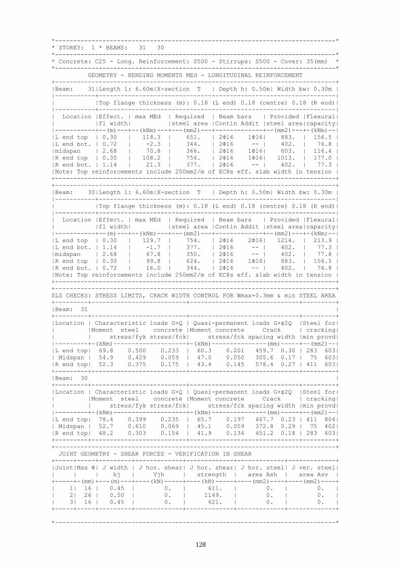
128
*-----------------------------------------------------------------------------*
* STOREY: 1 * BEAMS: 31 30
*-----------------------------------------------------------------------------*
* Concrete: C25 - Long. Reinforcement: S500 - Stirrups: S500 - Cover: 35(mm) *
*-----------------------------------------------------------------------------*
GEOMETRY - BENDING MOMENTS MEd - LONGITUDINAL REINFORCEMENT
+-----------------------------------------------------------------------------+
|Beam: 31|Length l: 6.60m|X-section T | Depth h: 0.50m| Width bw: 0.30m |
|-----------+-----------------------------------------------------------------|
| |Top flange thickness (m): 0.18 (L end) 0.18 (centre) 0.18 (R end)|
|-----------+-----------------------------------------------------------------|
| Location |Effect. | max MEd | Required | Beam bars | Provided |Flexural|
| |fl width| |steel area |Contin Addit |steel area|capacity|
|-----------+--(m)---+--(kNm)---+---(mm2)---+-------------+--(mm2)---+-(kNm)--|
|L end top | 0.30 | 118.3 | 651. | 2Φ16 1Φ16| 883. | 156.5 |
|L end bot. | 0.72 | -2.3 | 344. | 2Φ16 -- | 402. | 76.8 |
|midspan | 2.68 | 70.8 | 366. | 2Φ16 1Φ16| 603. | 116.4 |
|R end top | 0.30 | 108.2 | 754. | 2Φ16 1Φ16| 1013. | 177.0 |
|R end bot. | 1.14 | 21.3 | 377. | 2Φ16 -- | 402. | 77.3 |
|Note: Top reinforcements include 250mm2/m of EC8s eff. slab width in tension |
+-----------------------------------------------------------------------------+
+-----------------------------------------------------------------------------+
|Beam: 30|Length l: 6.60m|X-section T | Depth h: 0.50m| Width bw: 0.30m |
|-----------+-----------------------------------------------------------------|
| |Top flange thickness (m): 0.18 (L end) 0.18 (centre) 0.18 (R end)|
|-----------+-----------------------------------------------------------------|
| Location |Effect. | max MEd | Required | Beam bars | Provided |Flexural|
| |fl width| |steel area |Contin Addit |steel area|capacity|
|-----------+--(m)---+--(kNm)---+---(mm2)---+-------------+--(mm2)---+-(kNm)--|
|L end top | 0.30 | 129.7 | 754. | 2Φ16 2Φ16| 1214. | 213.9 |
|L end bot. | 1.14 | -1.7 | 377. | 2Φ16 -- | 402. | 77.3 |
|midspan | 2.68 | 67.8 | 350. | 2Φ16 -- | 402. | 77.8 |
|R end top | 0.30 | 99.8 | 624. | 2Φ16 1Φ16| 883. | 156.5 |
|R end bot. | 0.72 | 16.0 | 344. | 2Φ16 -- | 402. | 76.8 |
|Note: Top reinforcements include 250mm2/m of EC8s eff. slab width in tension |
+-----------------------------------------------------------------------------+
+-----------------------------------------------------------------------------+
SLS CHECKS: STRESS LIMITS, CRACK WIDTH CONTROL FOR Wmax=0.3mm & min STEEL AREA
+---------+--------------------------+------------------------------+---------+
|Beam: 31 |
+---------+--------------------------+------------------------------+---------+
|Location | Characteristic loads G+Q | Quasi-permanent loads G+ψ2Q |Steel for|
| |Moment steel concrete |Moment concrete Crack | cracking|
| | stress/fyk stress/fck| stress/fck spacing width |min provd|
|---------+-(kNm)--------------------+-(kNm)---------------(mm)-----+--(mm2)--|
|L end top| 69.8 0.500 0.233 | 60.3 0.201 459.7 0.30 | 283 603|
| Midspan | 54.9 0.429 0.059 | 47.0 0.050 305.6 0.17 | 75 603|
|R end top| 52.3 0.375 0.175 | 43.4 0.145 578.4 0.27 | 411 603|
+---------+--------------------------+------------------------------+---------+
|Beam: 30 |
+---------+--------------------------+------------------------------+---------+
|Location | Characteristic loads G+Q | Quasi-permanent loads G+ψ2Q |Steel for|
| |Moment steel concrete |Moment concrete Crack | cracking|
| | stress/fyk stress/fck| stress/fck spacing width |min provd|
|---------+-(kNm)--------------------+-(kNm)---------------(mm)-----+--(mm2)--|
|L end top| 78.4 0.399 0.235 | 65.7 0.197 467.7 0.23 | 411 804|
| Midspan | 52.7 0.610 0.069 | 45.1 0.059 372.8 0.29 | 75 402|
|R end top| 48.2 0.303 0.154 | 41.9 0.134 451.2 0.18 | 283 603|
+---------+--------------------------+------------------------------+---------+
+-----------------------------------------------------------------------------+
JOINT GEOMETRY - SHEAR FORCES - VERIFICATION IN SHEAR
+-----+-----+---------+-------------+-------------+-------------+-------------+
|Joint|Max Φ| J width | J hor. shear| J hor. shear| J hor. steel| J ver. steel|
| | | bj | Vjh | strength | area Ash | area Asv |
+-----+-(mm)+---(m)---+----(kN)-----+----(kN)-----+----(mm2)----+----(mm2)----+
| 1| 16 | 0.45 | 0. | 611. | 0. | 0. |
| 2| 26 | 0.50 | 0. | 1149. | 0. | 0. |
| 3| 16 | 0.45 | 0. | 621. | 0. | 0. |
+-----+-----+---------+-------------+-------------+-------------+-------------+
*-----------------------------------------------------------------------------*

129
* STOREY: 0 * BEAMS: 31 30 29
*-----------------------------------------------------------------------------*
* Concrete: C25 - Long. Reinforcement: S500 - Stirrups: S500 - Cover: 35(mm) *
*-----------------------------------------------------------------------------*
GEOMETRY - BENDING MOMENTS MEd - LONGITUDINAL REINFORCEMENT
+-----------------------------------------------------------------------------+
|Beam: 31|Length l: 6.60m|X-section T | Depth h: 0.50m| Width bw: 0.30m |
|-----------+-----------------------------------------------------------------|
| |Top flange thickness (m): 0.18 (L end) 0.18 (centre) 0.18 (R end)|
|-----------+-----------------------------------------------------------------|
| Location |Effect. | max MEd | Required | Beam bars | Provided |Flexural|
| |fl width| |steel area |Contin Addit |steel area|capacity|
|-----------+--(m)---+--(kNm)---+---(mm2)---+-------------+--(mm2)---+-(kNm)--|
|L end top | 0.30 | 210.6 | 1236. | 2Φ12 4Φ18| 1244. | 216.4 |
|L end bot. | 0.72 | -119.7 | 179. | 2Φ12 -- | 226. | 43.5 |
|midspan | 2.68 | 78.6 | 406. | 2Φ12 2Φ12| 452. | 87.5 |
|R end top | 0.30 | 88.1 | 476. | 2Φ12 3Φ18| 990. | 173.3 |
|R end bot. | 1.14 | -32.7 | 179. | 2Φ12 -- | 226. | 43.7 |
+-----------------------------------------------------------------------------+
+-----------------------------------------------------------------------------+
|Beam: 30|Length l: 6.60m|X-section T | Depth h: 0.50m| Width bw: 0.30m |
|-----------+-----------------------------------------------------------------|
| |Top flange thickness (m): 0.18 (L end) 0.18 (centre) 0.18 (R end)|
|-----------+-----------------------------------------------------------------|
| Location |Effect. | max MEd | Required | Beam bars | Provided |Flexural|
| |fl width| |steel area |Contin Addit |steel area|capacity|
|-----------+--(m)---+--(kNm)---+---(mm2)---+-------------+--(mm2)---+-(kNm)--|
|L end top | 0.30 | 133.4 | 741. | 2Φ12 3Φ18| 990. | 173.3 |
|L end bot. | 1.14 | -67.4 | 179. | 2Φ12 -- | 226. | 43.7 |
|midspan | 2.68 | 85.2 | 441. | 2Φ12 2Φ12| 452. | 87.5 |
|R end top | 0.30 | 152.0 | 855. | 2Φ12 3Φ16| 829. | 147.8 |
|R end bot. | 0.72 | -88.3 | 179. | 2Φ12 -- | 226. | 43.5 |
+-----------------------------------------------------------------------------+
+-----------------------------------------------------------------------------+
|Beam: 29|Length l: 6.70m|X-section T | Depth h: 0.50m| Width bw: 0.30m |
|-----------+-----------------------------------------------------------------|
| |Top flange thickness (m): 0.18 (L end) 0.18 (centre) 0.18 (R end)|
|-----------+-----------------------------------------------------------------|
| Location |Effect. | max MEd | Required | Beam bars | Provided |Flexural|
| |fl width| |steel area |Contin Addit |steel area|capacity|
|-----------+--(m)---+--(kNm)---+---(mm2)---+-------------+--(mm2)---+-(kNm)--|
|L end top | 0.30 | 115.7 | 636. | 2Φ12 3Φ16| 829. | 147.8 |
|L end bot. | 1.14 | -60.8 | 179. | 2Φ12 -- | 226. | 43.7 |
|midspan | 2.68 | 79.2 | 409. | 2Φ12 2Φ12| 452. | 87.5 |
|R end top | 0.30 | 195.7 | 1136. | 2Φ12 6Φ14| 1150. | 197.8 |
|R end bot. | 0.72 | -111.9 | 179. | 2Φ12 -- | 226. | 43.5 |
+-----------------------------------------------------------------------------+
+-----------------------------------------------------------------------------+
SLS CHECKS: STRESS LIMITS, CRACK WIDTH CONTROL FOR Wmax=0.3mm & min STEEL AREA
+---------+--------------------------+------------------------------+---------+
|Beam: 31 |
+---------+--------------------------+------------------------------+---------+
|Location | Characteristic loads G+Q | Quasi-permanent loads G+ψ2Q |Steel for|
| |Moment steel concrete |Moment concrete Crack | cracking|
| | stress/fyk stress/fck| stress/fck spacing width |min provd|
|---------+-(kNm)--------------------+-(kNm)---------------(mm)-----+--(mm2)--|
|L end top| 163.2 0.639 0.481 | 140.6 0.415 290.0 0.24 | 569 1244|
| Midspan | 61.0 0.631 0.075 | 52.1 0.064 300.0 0.24 | 75 452|
|R end top| 69.0 0.329 0.216 | 57.3 0.179 410.3 0.17 | 823 989|
+---------+--------------------------+------------------------------+---------+
|Beam: 30 |
+---------+--------------------------+------------------------------+---------+
|Location | Characteristic loads G+Q | Quasi-permanent loads G+ψ2Q |Steel for|
| |Moment steel concrete |Moment concrete Crack | cracking|
| | stress/fyk stress/fck| stress/fck spacing width |min provd|
|---------+-(kNm)--------------------+-(kNm)---------------(mm)-----+--(mm2)--|
|L end top| 104.1 0.456 0.317 | 87.4 0.266 404.4 0.23 | 823 989|
| Midspan | 66.2 0.684 0.082 | 56.6 0.070 300.0 0.26 | 75 452|
|R end top| 117.8 0.590 0.374 | 101.4 0.322 343.0 0.26 | 533 829|
+---------+--------------------------+------------------------------+---------+
|Beam: 29 |

130
+---------+--------------------------+------------------------------+---------+
|Location | Characteristic loads G+Q | Quasi-permanent loads G+ψ2Q |Steel for|
| |Moment steel concrete |Moment concrete Crack | cracking|
| | stress/fyk stress/fck| stress/fck spacing width |min provd|
|---------+-(kNm)--------------------+-(kNm)---------------(mm)-----+--(mm2)--|
|L end top| 89.8 0.450 0.285 | 76.9 0.244 426.3 0.25 | 777 829|
| Midspan | 61.6 0.636 0.076 | 52.4 0.065 300.0 0.24 | 75 452|
|R end top| 152.1 0.592 0.448 | 129.6 0.381 272.9 0.21 | 511 1149|
+---------+--------------------------+------------------------------+---------+
+-----------------------------------------------------------------------------+
*-----------------------------------------------------------------------------*
* STOREY: -1 * BEAMS: 31 30 29
*-----------------------------------------------------------------------------*
* Concrete: C25 - Long. Reinforcement: S500 - Stirrups: S500 - Cover: 35(mm) *
*-----------------------------------------------------------------------------*
GEOMETRY - BENDING MOMENTS MEd - LONGITUDINAL REINFORCEMENT
+-----------------------------------------------------------------------------+
|Beam: 31|Length l: 6.60m|X-section T | Depth h: 0.50m| Width bw: 0.30m |
|-----------+-----------------------------------------------------------------|
| |Top flange thickness (m): 0.18 (L end) 0.18 (centre) 0.18 (R end)|
|-----------+-----------------------------------------------------------------|
| Location |Effect. | max MEd | Required | Beam bars | Provided |Flexural|
| |fl width| |steel area |Contin Addit |steel area|capacity|
|-----------+--(m)---+--(kNm)---+---(mm2)---+-------------+--(mm2)---+-(kNm)--|
|L end top | 0.30 | 190.1 | 1099. | 2Φ12 8Φ12| 1131. | 194.9 |
|L end bot. | 0.72 | -114.6 | 179. | 2Φ12 -- | 226. | 43.5 |
|midspan | 2.68 | 82.9 | 429. | 2Φ12 2Φ12| 452. | 87.5 |
|R end top | 0.30 | 99.9 | 544. | 2Φ12 2Φ20| 855. | 151.9 |
|R end bot. | 1.14 | -54.1 | 179. | 2Φ12 -- | 226. | 43.7 |
+-----------------------------------------------------------------------------+
+-----------------------------------------------------------------------------+
|Beam: 30|Length l: 6.60m|X-section T | Depth h: 0.50m| Width bw: 0.30m |
|-----------+-----------------------------------------------------------------|
| |Top flange thickness (m): 0.18 (L end) 0.18 (centre) 0.18 (R end)|
|-----------+-----------------------------------------------------------------|
| Location |Effect. | max MEd | Required | Beam bars | Provided |Flexural|
| |fl width| |steel area |Contin Addit |steel area|capacity|
|-----------+--(m)---+--(kNm)---+---(mm2)---+-------------+--(mm2)---+-(kNm)--|
|L end top | 0.30 | 138.6 | 773. | 2Φ12 3Φ20| 1169. | 200.6 |
|L end bot. | 1.14 | -84.2 | 179. | 2Φ12 -- | 226. | 43.7 |
|midspan | 2.68 | 83.0 | 429. | 2Φ12 2Φ12| 452. | 87.5 |
|R end top | 0.30 | 151.2 | 850. | 2Φ12 4Φ14| 842. | 149.9 |
|R end bot. | 0.72 | -96.7 | 179. | 2Φ12 -- | 226. | 43.5 |
+-----------------------------------------------------------------------------+
+-----------------------------------------------------------------------------+
|Beam: 29|Length l: 6.70m|X-section T | Depth h: 0.50m| Width bw: 0.30m |
|-----------+-----------------------------------------------------------------|
| |Top flange thickness (m): 0.18 (L end) 0.18 (centre) 0.18 (R end)|
|-----------+-----------------------------------------------------------------|
| Location |Effect. | max MEd | Required | Beam bars | Provided |Flexural|
| |fl width| |steel area |Contin Addit |steel area|capacity|
|-----------+--(m)---+--(kNm)---+---(mm2)---+-------------+--(mm2)---+-(kNm)--|
|L end top | 0.30 | 127.3 | 704. | 2Φ12 4Φ14| 842. | 149.9 |
|L end bot. | 1.14 | -72.8 | 179. | 2Φ12 -- | 226. | 43.7 |
|midspan | 2.68 | 81.6 | 422. | 2Φ12 2Φ12| 452. | 87.5 |
|R end top | 0.30 | 179.3 | 1029. | 2Φ12 3Φ18| 990. | 173.3 |
|R end bot. | 0.72 | -103.0 | 179. | 2Φ12 -- | 226. | 43.5 |
+-----------------------------------------------------------------------------+
+-----------------------------------------------------------------------------+
SLS CHECKS: STRESS LIMITS, CRACK WIDTH CONTROL FOR Wmax=0.3mm & min STEEL AREA
+---------+--------------------------+------------------------------+---------+
|Beam: 31 |
+---------+--------------------------+------------------------------+---------+
|Location | Characteristic loads G+Q | Quasi-permanent loads G+ψ2Q |Steel for|
| |Moment steel concrete |Moment concrete Crack | cracking|
| | stress/fyk stress/fck| stress/fck spacing width |min provd|
|---------+-(kNm)--------------------+-(kNm)---------------(mm)-----+--(mm2)--|
|L end top| 147.2 0.626 0.445 | 126.9 0.383 262.9 0.21 | 482 1130|
| Midspan | 64.4 0.666 0.079 | 55.0 0.068 300.0 0.26 | 75 452|
|R end top| 78.1 0.422 0.254 | 65.1 0.211 469.1 0.25 | 838 854|

131
+---------+--------------------------+------------------------------+---------+
|Beam: 30 |
+---------+--------------------------+------------------------------+---------+
|Location | Characteristic loads G+Q | Quasi-permanent loads G+ψ2Q |Steel for|
| |Moment steel concrete |Moment concrete Crack | cracking|
| | stress/fyk stress/fck| stress/fck spacing width |min provd|
|---------+-(kNm)--------------------+-(kNm)---------------(mm)-----+--(mm2)--|
|L end top| 108.1 0.415 0.317 | 90.9 0.266 384.0 0.20 | 851 1168|
| Midspan | 64.5 0.666 0.079 | 55.1 0.068 300.0 0.26 | 75 452|
|R end top| 117.2 0.580 0.370 | 100.9 0.319 323.1 0.24 | 508 841|
+---------+--------------------------+------------------------------+---------+
|Beam: 29 |
+---------+--------------------------+------------------------------+---------+
|Location | Characteristic loads G+Q | Quasi-permanent loads G+ψ2Q |Steel for|
| |Moment steel concrete |Moment concrete Crack | cracking|
| | stress/fyk stress/fck| stress/fck spacing width |min provd|
|---------+-(kNm)--------------------+-(kNm)---------------(mm)-----+--(mm2)--|
|L end top| 98.8 0.489 0.312 | 84.6 0.267 398.4 0.25 | 740 841|
| Midspan | 63.4 0.655 0.078 | 53.9 0.066 300.0 0.25 | 75 452|
|R end top| 139.4 0.610 0.425 | 118.7 0.362 324.9 0.25 | 565 989|
+---------+--------------------------+------------------------------+---------+
+-----------------------------------------------------------------------------+
The beam framing plans for all storeys are shown in Figures 6.1 to 6.8, where the longitudinal
reinforcement of the top and bottom flange is indicated at the ends of beams and the longitudinal
reinforcement at the bottom flange is given at the midspan. Because of symmetry, the transverse
reinforcement at the ends and the midspan of beams is indicated at the right half of the plan.

132
Fig. 6.1 Beam framing plan at roof
A
B
1 2 3 4 5 6
C
Roof

133
Fig. 6.2 Beam framing plan at storey 5
A
B
1 2 3 4 5 6
C
Level 5

134
Fig. 6.3 Beam framing plan at storey 4
A
B
1 2 3 4 5 6
C
Level 4

135
Fig. 6.4 Beam framing plan at storey 3
A
B
1 2 3 4 5 6
C
Level 3

136
Fig. 6.5 Beam framing plan at storey 2
A
B
1 2 3 4 5 6
C
Level 2
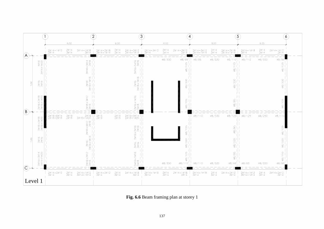
137
Fig. 6.6 Beam framing plan at storey 1
A
B
1 2 3 4 5 6
C
Level 1

138
Fig. 6.7 Beam framing plan at storey 0
A
B
D
1 2 3 4 5 6
C
Level 0

139
Fig. 6.8 Beam framing plan at storey -1
A
B
D
1 2 3 4 5 6
C
Level -1

140
7 Design of columns
7.1 Column C1
*-----------------------------------------------------------------------------*
* COLUMN: 1 *
*-----------------------------------------------------------------------------*
* Concrete: C25 - Long. Reinforcement: S500 - Stirrups: S500 - Cover: 35(mm) *
*-----------------------------------------------------------------------------*
NORMAL STRESS-RESULTANTS
*-----------------------------------------------------------------------------*
| STOREY: 6 | Base | Top |
|Actions Combination| My Mz N | My Mz N |
|-------------------+----(kNm)----(kNm)-----(kN)-+----(kNm)----(kNm)-----(kN)-|
| EN1990 Eq. 6.10a | -25.7 17.4 111.5 | 30.1 -23.2 93.3 |
| EN1990 Eq. 6.10b | -24.4 16.4 104.0 | 28.6 -21.9 88.5 |
| G+ψ2Q+E +X +Y/maxN| 26.2 143.3 147.0 | 68.4 159.5 133.5 |
| G+ψ2Q+E -X +Y/maxN| -60.3 143.3 147.0 | -28.6 159.5 133.5 |
| G+ψ2Q+E +X -Y/maxN| 26.2 -120.2 147.0 | 68.4 -190.5 133.5 |
| G+ψ2Q+E -X -Y/maxN| -60.3 -120.2 147.0 | -28.6 -190.5 133.5 |
| G+ψ2Q+E +X +Y/minN| 26.2 143.3 3.6 | 68.4 159.5 -9.9 |
| G+ψ2Q+E -X +Y/minN| -60.3 143.3 3.6 | -28.6 159.5 -9.9 |
| G+ψ2Q+E +X -Y/minN| 26.2 -120.2 3.6 | 68.4 -190.5 -9.9 |
| G+ψ2Q+E -X -Y/minN| -60.3 -120.2 3.6 | -28.6 -190.5 -9.9 |
+-----------------------------------------------------------------------------+
| STOREY: 5 | Base | Top |
|Actions Combination| My Mz N | My Mz N |
|-------------------+----(kNm)----(kNm)-----(kN)-+----(kNm)----(kNm)-----(kN)-|
| EN1990 Eq. 6.10a | -22.1 14.8 230.0 | 21.8 -13.8 211.7 |
| EN1990 Eq. 6.10b | -21.0 13.9 214.6 | 20.7 -13.0 199.1 |
| G+ψ2Q+E +X +Y/maxN| 30.5 126.7 319.4 | 60.1 102.4 305.9 |
| G+ψ2Q+E -X +Y/maxN| -59.7 126.7 319.4 | -31.2 102.4 305.9 |
| G+ψ2Q+E +X -Y/maxN| 30.5 -106.9 319.4 | 60.1 -120.8 305.9 |
| G+ψ2Q+E -X -Y/maxN| -59.7 -106.9 319.4 | -31.2 -120.8 305.9 |
| G+ψ2Q+E +X +Y/minN| 30.5 126.7 -8.8 | 60.1 102.4 -22.3 |
| G+ψ2Q+E -X +Y/minN| -59.7 126.7 -8.8 | -31.2 102.4 -22.3 |
| G+ψ2Q+E +X -Y/minN| 30.5 -106.9 -8.8 | 60.1 -120.8 -22.3 |
| G+ψ2Q+E -X -Y/minN| -59.7 -106.9 -8.8 | -31.2 -120.8 -22.3 |
+-----------------------------------------------------------------------------+
| STOREY: 4 | Base | Top |
|Actions Combination| My Mz N | My Mz N |
|-------------------+----(kNm)----(kNm)-----(kN)-+----(kNm)----(kNm)-----(kN)-|
| EN1990 Eq. 6.10a | -21.7 16.6 347.7 | 22.1 -16.7 329.5 |
| EN1990 Eq. 6.10b | -20.6 15.6 324.5 | 21.0 -15.8 309.0 |
| G+ψ2Q+E +X +Y/maxN| 34.6 135.7 491.6 | 64.0 113.0 478.1 |
| G+ψ2Q+E -X +Y/maxN| -63.3 135.7 491.6 | -34.8 113.0 478.1 |
| G+ψ2Q+E +X -Y/maxN| 34.6 -113.6 491.6 | 64.0 -135.4 478.1 |
| G+ψ2Q+E -X -Y/maxN| -63.3 -113.6 491.6 | -34.8 -135.4 478.1 |
| G+ψ2Q+E +X +Y/minN| 34.6 135.7 -22.1 | 64.0 113.0 -35.6 |
| G+ψ2Q+E -X +Y/minN| -63.3 135.7 -22.1 | -34.8 113.0 -35.6 |
| G+ψ2Q+E +X -Y/minN| 34.6 -113.6 -22.1 | 64.0 -135.4 -35.6 |
| G+ψ2Q+E -X -Y/minN| -63.3 -113.6 -22.1 | -34.8 -135.4 -35.6 |
+-----------------------------------------------------------------------------+
| STOREY: 3 | Base | Top |
|Actions Combination| My Mz N | My Mz N |
|-------------------+----(kNm)----(kNm)-----(kN)-+----(kNm)----(kNm)-----(kN)-|
| EN1990 Eq. 6.10a | -20.2 17.2 465.8 | 20.8 -17.8 447.6 |
| EN1990 Eq. 6.10b | -19.2 16.2 434.8 | 19.8 -16.8 419.3 |
| G+ψ2Q+E +X +Y/maxN| 36.7 131.8 663.2 | 63.8 102.5 649.7 |
| G+ψ2Q+E -X +Y/maxN| -63.4 131.8 663.2 | -36.3 102.5 649.7 |
| G+ψ2Q+E +X -Y/maxN| 36.7 -108.9 663.2 | 63.8 -126.3 649.7 |
| G+ψ2Q+E -X -Y/maxN| -63.4 -108.9 663.2 | -36.3 -126.3 649.7 |
| G+ψ2Q+E +X +Y/minN| 36.7 131.8 -34.1 | 63.8 102.5 -47.6 |
| G+ψ2Q+E -X +Y/minN| -63.4 131.8 -34.1 | -36.3 102.5 -47.6 |
| G+ψ2Q+E +X -Y/minN| 36.7 -108.9 -34.1 | 63.8 -126.3 -47.6 |
| G+ψ2Q+E -X -Y/minN| -63.4 -108.9 -34.1 | -36.3 -126.3 -47.6 |
+-----------------------------------------------------------------------------+
| STOREY: 2 | Base | Top |
|Actions Combination| My Mz N | My Mz N |
|-------------------+----(kNm)----(kNm)-----(kN)-+----(kNm)----(kNm)-----(kN)-|

141
| EN1990 Eq. 6.10a | -21.1 24.3 584.9 | 20.3 -21.7 566.6 |
| EN1990 Eq. 6.10b | -20.0 23.0 546.0 | 19.3 -20.5 530.5 |
| G+ψ2Q+E +X +Y/maxN| 36.2 129.4 826.8 | 61.2 82.4 813.3 |
| G+ψ2Q+E -X +Y/maxN| -64.1 129.4 826.8 | -34.3 82.4 813.3 |
| G+ψ2Q+E +X -Y/maxN| 36.2 -97.0 826.8 | 61.2 -111.3 813.3 |
| G+ψ2Q+E -X -Y/maxN| -64.1 -97.0 826.8 | -34.3 -111.3 813.3 |
| G+ψ2Q+E +X +Y/minN| 36.2 129.4 -37.1 | 61.2 82.4 -50.6 |
| G+ψ2Q+E -X +Y/minN| -64.1 129.4 -37.1 | -34.3 82.4 -50.6 |
| G+ψ2Q+E +X -Y/minN| 36.2 -97.0 -37.1 | 61.2 -111.3 -50.6 |
| G+ψ2Q+E -X -Y/minN| -64.1 -97.0 -37.1 | -34.3 -111.3 -50.6 |
+-----------------------------------------------------------------------------+
| STOREY: 1 | Base | Top |
|Actions Combination| My Mz N | My Mz N |
|-------------------+----(kNm)----(kNm)-----(kN)-+----(kNm)----(kNm)-----(kN)-|
| EN1990 Eq. 6.10a | -5.5 6.9 708.3 | 11.0 -16.0 684.0 |
| EN1990 Eq. 6.10b | -5.2 6.4 660.6 | 10.5 -15.1 640.0 |
| G+ψ2Q+E +X +Y/maxN| 33.8 84.2 973.9 | 39.3 39.6 955.9 |
| G+ψ2Q+E -X +Y/maxN| -41.1 84.2 973.9 | -24.6 39.6 955.9 |
| G+ψ2Q+E +X -Y/maxN| 33.8 -75.0 973.9 | 39.3 -61.0 955.9 |
| G+ψ2Q+E -X -Y/maxN| -41.1 -75.0 973.9 | -24.6 -61.0 955.9 |
| G+ψ2Q+E +X +Y/minN| 33.8 84.2 -16.9 | 39.3 39.6 -34.9 |
| G+ψ2Q+E -X +Y/minN| -41.1 84.2 -16.9 | -24.6 39.6 -34.9 |
| G+ψ2Q+E +X -Y/minN| 33.8 -75.0 -16.9 | 39.3 -61.0 -34.9 |
| G+ψ2Q+E -X -Y/minN| -41.1 -75.0 -16.9 | -24.6 -61.0 -34.9 |
+-----------------------------------------------------------------------------+
FOR NEGLIGIBLE 2ND-ORDER EFFECTS IN COLUMN, per EC2 pa.5.8.3.1, 5.8.3.2, 5.8.7.2
+-----------------------------------------------------------------------------+
|Storey| Combination| column direction x | column direction z |
| | of actions | slenderness column | slenderness column |
| | per EN1990 |limit actual eff.l0 req.size|limit actual eff.l0 req.size|
+------+------------+-------------------(m)------+-------------------(m)------+
| 6 | Eq. 6.10a |262.2 17.1 1.48 0.30|250.7 9.1 1.58 0.60|
| | Eq. 6.10b |265.4 17.1 1.48 0.30|253.2 9.1 1.58 0.60|
+------+------------+----------------------------+----------------------------+
| 5 | Eq. 6.10a |171.5 17.1 1.48 0.30|167.3 9.1 1.57 0.60|
| | Eq. 6.10b |174.9 17.1 1.48 0.30|170.2 9.1 1.57 0.60|
+------+------------+----------------------------+----------------------------+
| 4 | Eq. 6.10a |150.8 17.1 1.48 0.30|150.9 9.1 1.57 0.60|
| | Eq. 6.10b |153.8 17.1 1.48 0.30|153.5 9.1 1.57 0.60|
+------+------------+----------------------------+----------------------------+
| 3 | Eq. 6.10a |130.1 17.1 1.48 0.30|129.4 9.1 1.58 0.60|
| | Eq. 6.10b |132.7 17.1 1.48 0.30|131.8 9.1 1.58 0.60|
+------+------------+----------------------------+----------------------------+
| 2 | Eq. 6.10a |115.4 17.3 1.50 0.30|119.2 9.2 1.59 0.60|
| | Eq. 6.10b |118.1 17.3 1.50 0.30|122.0 9.2 1.59 0.60|
+------+------------+----------------------------+----------------------------+
| 1 | Eq. 6.10a | 87.7 24.0 2.08 0.30| 84.8 12.8 2.21 0.60|
| | Eq. 6.10b | 89.7 24.0 2.08 0.30| 86.4 12.8 2.21 0.60|
+------+------------+----------------------------+----------------------------+
GEOMETRY & LONGITUDINAL REINFORCEMENT
+-----------------------------------------------------------------------------+
|Storey 6 Clear height(m):2.50 hcr(m):0.60 X-sect. RECT by(m):0.60 bz(m):0.30|
+-----------------------------------------------------------------------------+
| Vertical steel ratio: 0.0108, Bars: 4Φ18 & 6Φ14 |
| 2Φ18 & 2Φ14 along by 2Φ18 & 1Φ14 along bz |
+-----------------------------------------------------------------------------+
|Storey 5 Clear height(m):2.50 hcr(m):0.60 X-sect. RECT by(m):0.60 bz(m):0.30|
+-----------------------------------------------------------------------------+
| Vertical steel ratio: 0.0108, Bars: 4Φ18 & 6Φ14 |
| 2Φ18 & 2Φ14 along by 2Φ18 & 1Φ14 along bz |
+-----------------------------------------------------------------------------+
|Storey 4 Clear height(m):2.50 hcr(m):0.60 X-sect. RECT by(m):0.60 bz(m):0.30|
+-----------------------------------------------------------------------------+
| Vertical steel ratio: 0.0108, Bars: 4Φ18 & 6Φ14 |
| 2Φ18 & 2Φ14 along by 2Φ18 & 1Φ14 along bz |
+-----------------------------------------------------------------------------+
|Storey 3 Clear height(m):2.50 hcr(m):0.60 X-sect. RECT by(m):0.60 bz(m):0.30|
+-----------------------------------------------------------------------------+
| Vertical steel ratio: 0.0108, Bars: 4Φ18 & 6Φ14 |
| 2Φ18 & 2Φ14 along by 2Φ18 & 1Φ14 along bz |
+-----------------------------------------------------------------------------+
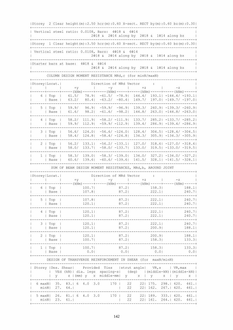
142
|Storey 2 Clear height(m):2.50 hcr(m):0.60 X-sect. RECT by(m):0.60 bz(m):0.30|
+-----------------------------------------------------------------------------+
| Vertical steel ratio: 0.0108, Bars: 4Φ18 & 6Φ14 |
| 2Φ18 & 2Φ14 along by 2Φ18 & 1Φ14 along bz |
+-----------------------------------------------------------------------------+
|Storey 1 Clear height(m):3.50 hcr(m):0.60 X-sect. RECT by(m):0.60 bz(m):0.30|
+-----------------------------------------------------------------------------+
| Vertical steel ratio: 0.0108, Bars: 4Φ18 & 6Φ14 |
| 2Φ18 & 2Φ14 along by 2Φ18 & 1Φ14 along bz |
+-----------------------------------------------------------------------------+
|Starter bars at base: 4Φ18 & 6Φ14 |
| 2Φ18 & 2Φ14 along by 2Φ18 & 1Φ14 along bz |
+-----------------------------------------------------------------------------+
COLUMN DESIGN MOMENT RESISTANCE MRd,c (for minN/maxN)
+-----------------------------------------------------------------------------+
|Storey|Locat.| Direction of MRd Vector : |
| | | +y | -y | +z | -z |
+------+------+-----(kNm)-----+-----(kNm)-----+-----(kNm)-----+-----(kNm)-----+
| 6 | Top | 61.5/ 78.9| -61.5/ -78.9| 144.4/ 193.1| -144.4/ -193.1|
| | Base | 63.2/ 80.4| -63.2/ -80.4| 149.7/ 197.0| -149.7/ -197.0|
+-----------------------------------------------------------------------------+
| 5 | Top | 59.9/ 96.9| -59.9/ -96.9| 139.3/ 260.9| -139.3/ -260.9|
| | Base | 61.6/ 98.2| -61.6/ -98.2| 144.8/ 263.0| -144.8/ -263.0|
+-----------------------------------------------------------------------------+
| 4 | Top | 58.2/ 111.9| -58.2/ -111.9| 133.7/ 285.2| -133.7/ -285.2|
| | Base | 59.9/ 112.9| -59.9/ -112.9| 139.4/ 286.9| -139.4/ -286.9|
+-----------------------------------------------------------------------------+
| 3 | Top | 56.6/ 124.0| -56.6/ -124.0| 128.4/ 304.5| -128.4/ -304.5|
| | Base | 58.4/ 124.8| -58.4/ -124.8| 134.3/ 305.9| -134.3/ -305.9|
+-----------------------------------------------------------------------------+
| 2 | Top | 56.2/ 133.1| -56.2/ -133.1| 127.0/ 318.6| -127.0/ -318.6|
| | Base | 58.0/ 133.7| -58.0/ -133.7| 133.0/ 319.5| -133.0/ -319.5|
+-----------------------------------------------------------------------------+
| 1 | Top | 58.3/ 139.0| -58.3/ -139.0| 134.0/ 327.2| -134.0/ -327.2|
| | Base | 60.6/ 139.6| -60.6/ -139.6| 141.5/ 328.1| -141.5/ -328.1|
+-----------------------------------------------------------------------------+
SUM OF BEAM DESIGN MOMENT RESISTANCES, MRd,b, AROUND JOINT
+-----------------------------------------------------------------------------+
|Storey|Locat.| Direction of MRd Vector : |
| | | +y | -y | +z | -z |
+------+------+-----(kNm)-----+-----(kNm)-----+-----(kNm)-----+-----(kNm)-----+
| 6 | Top | 100.7| 87.2| 158.3| 188.1|
| | Base | 107.8| 87.2| 222.1| 240.7|
+-----------------------------------------------------------------------------+
| 5 | Top | 107.8| 87.2| 222.1| 240.7|
| | Base | 120.1| 87.2| 222.1| 240.7|
+-----------------------------------------------------------------------------+
| 4 | Top | 120.1| 87.2| 222.1| 240.7|
| | Base | 120.1| 87.2| 222.1| 240.7|
+-----------------------------------------------------------------------------+
| 3 | Top | 120.1| 87.2| 222.1| 240.7|
| | Base | 120.1| 87.2| 200.9| 188.1|
+-----------------------------------------------------------------------------+
| 2 | Top | 120.1| 87.2| 200.9| 188.1|
| | Base | 100.7| 87.2| 158.3| 133.3|
+-----------------------------------------------------------------------------+
| 1 | Top | 100.7| 87.2| 158.3| 133.3|
| | Base | 0.0| 0.0| 0.0| 0.0|
+-----------------------------------------------------------------------------+
DESIGN OF TRANSVERSE REINFORCEMENT IN SHEAR (for maxN/minN)
+-----------------------------------------------------------------------------+
| Storey |Des. Shear| Provided Ties |strut angle| VR,s | VR,max |
| | VEd (kN)| dia. legs spacing-s| (deg) |(middle-kN)|(middle-kN)|
| | y z |(mm) y z middle-mm| y z | y z | y z |
+--------+----------+---------------------+-----------+-----------+-----------+
| 6 maxN| 35. 83.| 6 4.0 3.0 170 | 22 22| 175. 298.| 420. 461.|
| minN| 27. 64.| | 22 22| 162. 267.| 420. 461.|
+-----------------------------------------------------------------------------+
| 5 maxN| 26. 81.| 6 4.0 3.0 170 | 22 22| 189. 333.| 420. 461.|
| minN| 23. 61.| | 22 22| 161. 264.| 420. 461.|
+-----------------------------------------------------------------------------+

143
| 4 maxN| 28. 77.| 6 4.0 3.0 170 | 22 22| 203. 367.| 420. 461.|
| minN| 26. 59.| | 22 22| 160. 262.| 420. 461.|
+-----------------------------------------------------------------------------+
| 3 maxN| 28. 76.| 6 4.0 3.0 170 | 22 22| 216. 402.| 420. 461.|
| minN| 25. 56.| | 22 22| 159. 259.| 420. 461.|
+-----------------------------------------------------------------------------+
| 2 maxN| 27. 63.| 6 4.0 3.0 170 | 22 22| 230. 434.| 420. 461.|
| minN| 25. 56.| | 22 22| 159. 259.| 420. 461.|
+-----------------------------------------------------------------------------+
| 1 maxN| 60. 139.| 6 4.0 3.0 170 | 22 22| 219. 408.| 420. 461.|
| minN| 35. 80.| | 22 22| 161. 264.| 420. 461.|
+-----------------------------------------------------------------------------+
CONFINEMENT REINFORCEMENT AT COLUMN ENDS (for maxN/minN)
+-----------------------------------------------------------------------------+
|Story| Wwd-req. | aWwd-req. | Stirrups | Wwd-prov. | aWwd-prov. |
| | base top | base top |dia. legs spacing-mm| base top | base top |
| | | |(mm) y z base top| | |
+-----+----------+-----------+----------------------+------------+------------+
| 6 | 0.00 0.00|0.000 0.000| 6 4.0 3.0 110 110| 0.152 0.152| 0.052 0.052|
+-----------------------------------------------------------------------------+
| 5 | 0.00 0.00|0.000 0.000| 6 4.0 3.0 110 110| 0.152 0.152| 0.052 0.052|
+-----------------------------------------------------------------------------+
| 4 | 0.00 0.00|0.000 0.000| 6 4.0 3.0 110 110| 0.152 0.152| 0.052 0.052|
+-----------------------------------------------------------------------------+
| 3 | 0.00 0.00|0.000 0.000| 6 4.0 3.0 110 110| 0.152 0.152| 0.052 0.052|
+-----------------------------------------------------------------------------+
| 2 | 0.00 0.00|0.000 0.000| 6 4.0 3.0 110 110| 0.152 0.152| 0.052 0.052|
+-----------------------------------------------------------------------------+
| 1 | 0.08 0.00|0.110 0.000| 8 4.0 3.0 100 110| 0.296 0.269| 0.108 0.093|
+-----------------------------------------------------------------------------+
STOREY: 0 CAPACITY DESIGN FACTOR FOR FOUNDATION
+-----------------------------------------------------------------------------+
|Actions Combination| MRd,y | MEd,y | aCD,y| MRd,z | MEd,z | aCD,z| acD |
|-------------------+--(kNm)-+--(kNm)-+------+--(kNm)-+--(kNm)-+------+-------|
| G+ψ2Q+E +X +Y/maxN| 139.6| 33.8| 4.95| 328.1| 84.2| 3.90| 3.000|
| G+ψ2Q+E -X +Y/maxN| 139.6| 41.1| 4.08| 328.1| 84.2| 3.90| 3.000|
| G+ψ2Q+E +X -Y/maxN| 139.6| 33.8| 4.95| 328.1| 75.0| 4.38| 3.000|
| G+ψ2Q+E -X -Y/maxN| 139.6| 41.1| 4.08| 328.1| 75.0| 4.38| 3.000|
| G+ψ2Q+E +X +Y/minN| 60.6| 33.8| 2.15| 141.5| 84.2| 1.68| 1.681|
| G+ψ2Q+E -X +Y/minN| 60.6| 41.1| 1.77| 141.5| 84.2| 1.68| 1.681|
| G+ψ2Q+E +X -Y/minN| 60.6| 33.8| 2.15| 141.5| 75.0| 1.89| 1.888|
| G+ψ2Q+E -X -Y/minN| 60.6| 41.1| 1.77| 141.5| 75.0| 1.89| 1.770|
+-----------------------------------------------------------------------------+
7.2 Column C2
*-----------------------------------------------------------------------------*
* COLUMN: 2 *
*-----------------------------------------------------------------------------*
* Concrete: C25 - Long. Reinforcement: S500 - Stirrups: S500 - Cover: 35(mm) *
*-----------------------------------------------------------------------------*
NORMAL STRESS-RESULTANTS
*-----------------------------------------------------------------------------*
| STOREY: 6 | Base | Top |
|Actions Combination| My Mz N | My Mz N |
|-------------------+----(kNm)----(kNm)-----(kN)-+----(kNm)----(kNm)-----(kN)-|
| EN1990 Eq. 6.10a | 2.6 97.8 274.7 | -6.5 -113.8 253.4 |
| EN1990 Eq. 6.10b | 2.5 92.8 258.7 | -6.1 -108.0 240.6 |
| G+ψ2Q+E +X +Y/maxN| 124.2 115.8 205.6 | 154.8 -17.8 189.9 |
| G+ψ2Q+E -X +Y/maxN| -120.7 115.8 205.6 | -163.4 -17.8 189.9 |
| G+ψ2Q+E +X -Y/maxN| 124.2 13.9 205.6 | 154.8 -133.1 189.9 |
| G+ψ2Q+E -X -Y/maxN| -120.7 13.9 205.6 | -163.4 -133.1 189.9 |
| G+ψ2Q+E +X +Y/minN| 124.2 115.8 161.7 | 154.8 -17.8 146.0 |
| G+ψ2Q+E -X +Y/minN| -120.7 115.8 161.7 | -163.4 -17.8 146.0 |
| G+ψ2Q+E +X -Y/minN| 124.2 13.9 161.7 | 154.8 -133.1 146.0 |
| G+ψ2Q+E -X -Y/minN| -120.7 13.9 161.7 | -163.4 -133.1 146.0 |
+-----------------------------------------------------------------------------+
| STOREY: 5 | Base | Top |
|Actions Combination| My Mz N | My Mz N |
|-------------------+----(kNm)----(kNm)-----(kN)-+----(kNm)----(kNm)-----(kN)-|
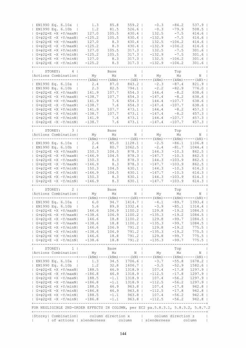
144
| EN1990 Eq. 6.10a | 1.3 85.8 559.2 | -0.3 -84.2 537.9 |
| EN1990 Eq. 6.10b | 1.2 81.5 526.6 | -0.3 -79.9 508.5 |
| G+ψ2Q+E +X +Y/maxN| 127.0 105.5 430.4 | 132.5 -7.5 414.6 |
| G+ψ2Q+E -X +Y/maxN| -125.2 105.5 430.4 | -132.9 -7.5 414.6 |
| G+ψ2Q+E +X -Y/maxN| 127.0 8.3 430.4 | 132.5 -104.2 414.6 |
| G+ψ2Q+E -X -Y/maxN| -125.2 8.3 430.4 | -132.9 -104.2 414.6 |
| G+ψ2Q+E +X +Y/minN| 127.0 105.5 317.3 | 132.5 -7.5 301.6 |
| G+ψ2Q+E -X +Y/minN| -125.2 105.5 317.3 | -132.9 -7.5 301.6 |
| G+ψ2Q+E +X -Y/minN| 127.0 8.3 317.3 | 132.5 -104.2 301.6 |
| G+ψ2Q+E -X -Y/minN| -125.2 8.3 317.3 | -132.9 -104.2 301.6 |
+-----------------------------------------------------------------------------+
| STOREY: 4 | Base | Top |
|Actions Combination| My Mz N | My Mz N |
|-------------------+----(kNm)----(kNm)-----(kN)-+----(kNm)----(kNm)-----(kN)-|
| EN1990 Eq. 6.10a | 2.4 87.0 843.2 | -2.3 -87.4 821.9 |
| EN1990 Eq. 6.10b | 2.3 82.5 794.1 | -2.2 -82.9 776.0 |
| G+ψ2Q+E +X +Y/maxN| 141.9 107.7 654.3 | 144.4 -8.2 638.6 |
| G+ψ2Q+E -X +Y/maxN| -138.7 107.7 654.3 | -147.4 -8.2 638.6 |
| G+ψ2Q+E +X -Y/maxN| 141.9 7.6 654.3 | 144.4 -107.7 638.6 |
| G+ψ2Q+E -X -Y/maxN| -138.7 7.6 654.3 | -147.4 -107.7 638.6 |
| G+ψ2Q+E +X +Y/minN| 141.9 107.7 473.1 | 144.4 -8.2 457.3 |
| G+ψ2Q+E -X +Y/minN| -138.7 107.7 473.1 | -147.4 -8.2 457.3 |
| G+ψ2Q+E +X -Y/minN| 141.9 7.6 473.1 | 144.4 -107.7 457.3 |
| G+ψ2Q+E -X -Y/minN| -138.7 7.6 473.1 | -147.4 -107.7 457.3 |
+-----------------------------------------------------------------------------+
| STOREY: 3 | Base | Top |
|Actions Combination| My Mz N | My Mz N |
|-------------------+----(kNm)----(kNm)-----(kN)-+----(kNm)----(kNm)-----(kN)-|
| EN1990 Eq. 6.10a | 2.6 85.0 1128.1 | -2.5 -86.1 1106.8 |
| EN1990 Eq. 6.10b | 2.4 80.7 1062.5 | -2.4 -81.7 1044.4 |
| G+ψ2Q+E +X +Y/maxN| 150.3 104.5 878.3 | 144.3 -10.3 862.5 |
| G+ψ2Q+E -X +Y/maxN| -146.9 104.5 878.3 | -147.7 -10.3 862.5 |
| G+ψ2Q+E +X -Y/maxN| 150.3 8.3 878.3 | 144.3 -103.9 862.5 |
| G+ψ2Q+E -X -Y/maxN| -146.9 8.3 878.3 | -147.7 -103.9 862.5 |
| G+ψ2Q+E +X +Y/minN| 150.3 104.5 630.1 | 144.3 -10.3 614.3 |
| G+ψ2Q+E -X +Y/minN| -146.9 104.5 630.1 | -147.7 -10.3 614.3 |
| G+ψ2Q+E +X -Y/minN| 150.3 8.3 630.1 | 144.3 -103.9 614.3 |
| G+ψ2Q+E -X -Y/minN| -146.9 8.3 630.1 | -147.7 -103.9 614.3 |
+-----------------------------------------------------------------------------+
| STOREY: 2 | Base | Top |
|Actions Combination| My Mz N | My Mz N |
|-------------------+----(kNm)----(kNm)-----(kN)-+----(kNm)----(kNm)-----(kN)-|
| EN1990 Eq. 6.10a | 6.0 94.7 1414.7 | -4.1 -89.7 1393.4 |
| EN1990 Eq. 6.10b | 5.6 89.9 1332.4 | -3.9 -85.1 1314.4 |
| G+ψ2Q+E +X +Y/maxN| 146.6 106.9 1100.2 | 129.8 -19.2 1084.5 |
| G+ψ2Q+E -X +Y/maxN| -138.6 106.9 1100.2 | -135.3 -19.2 1084.5 |
| G+ψ2Q+E +X -Y/maxN| 146.6 18.8 1100.2 | 129.8 -99.7 1084.5 |
| G+ψ2Q+E -X -Y/maxN| -138.6 18.8 1100.2 | -135.3 -99.7 1084.5 |
| G+ψ2Q+E +X +Y/minN| 146.6 106.9 791.2 | 129.8 -19.2 775.5 |
| G+ψ2Q+E -X +Y/minN| -138.6 106.9 791.2 | -135.3 -19.2 775.5 |
| G+ψ2Q+E +X -Y/minN| 146.6 18.8 791.2 | 129.8 -99.7 775.5 |
| G+ψ2Q+E -X -Y/minN| -138.6 18.8 791.2 | -135.3 -99.7 775.5 |
+-----------------------------------------------------------------------------+
| STOREY: 1 | Base | Top |
|Actions Combination| My Mz N | My Mz N |
|-------------------+----(kNm)----(kNm)-----(kN)-+----(kNm)----(kNm)-----(kN)-|
| EN1990 Eq. 6.10a | 1.3 34.5 1706.6 | -3.7 -55.8 1678.2 |
| EN1990 Eq. 6.10b | 1.2 32.8 1606.7 | -3.5 -52.9 1582.6 |
| G+ψ2Q+E +X +Y/maxN| 188.5 46.9 1318.9 | 107.4 -17.8 1297.9 |
| G+ψ2Q+E -X +Y/maxN| -186.8 46.9 1318.9 | -112.5 -17.8 1297.9 |
| G+ψ2Q+E +X -Y/maxN| 188.5 -1.1 1318.9 | 107.4 -56.2 1297.9 |
| G+ψ2Q+E -X -Y/maxN| -186.8 -1.1 1318.9 | -112.5 -56.2 1297.9 |
| G+ψ2Q+E +X +Y/minN| 188.5 46.9 963.8 | 107.4 -17.8 942.8 |
| G+ψ2Q+E -X +Y/minN| -186.8 46.9 963.8 | -112.5 -17.8 942.8 |
| G+ψ2Q+E +X -Y/minN| 188.5 -1.1 963.8 | 107.4 -56.2 942.8 |
| G+ψ2Q+E -X -Y/minN| -186.8 -1.1 963.8 | -112.5 -56.2 942.8 |
+-----------------------------------------------------------------------------+
FOR NEGLIGIBLE 2ND-ORDER EFFECTS IN COLUMN, per EC2 pa.5.8.3.1, 5.8.3.2, 5.8.7.2
+-----------------------------------------------------------------------------+
|Storey| Combination| column direction x | column direction z |
| | of actions | slenderness column | slenderness column |

145
| | per EN1990 |limit actual eff.l0 req.size|limit actual eff.l0 req.size|
+------+------------+-------------------(m)------+-------------------(m)------+
| 6 | Eq. 6.10a |141.7 8.0 1.62 0.70|172.3 17.1 1.48 0.30|
| | Eq. 6.10b |143.1 8.0 1.62 0.70|174.3 17.0 1.48 0.30|
+------+------------+----------------------------+----------------------------+
| 5 | Eq. 6.10a | 70.9 8.0 1.61 0.70|119.4 17.1 1.48 0.30|
| | Eq. 6.10b | 70.8 8.0 1.61 0.70|121.2 17.0 1.48 0.30|
+------+------------+----------------------------+----------------------------+
| 4 | Eq. 6.10a |112.9 7.9 1.61 0.70|103.7 17.2 1.49 0.30|
| | Eq. 6.10b |115.2 7.9 1.61 0.70|105.3 17.2 1.49 0.30|
+------+------------+----------------------------+----------------------------+
| 3 | Eq. 6.10a | 90.4 7.9 1.60 0.70| 89.9 17.3 1.50 0.30|
| | Eq. 6.10b | 91.8 7.9 1.60 0.70| 91.4 17.3 1.49 0.30|
+------+------------+----------------------------+----------------------------+
| 2 | Eq. 6.10a | 82.1 8.0 1.61 0.70| 80.8 17.4 1.51 0.30|
| | Eq. 6.10b | 84.0 8.0 1.61 0.70| 82.4 17.4 1.51 0.30|
+------+------------+----------------------------+----------------------------+
| 1 | Eq. 6.10a | 56.0 11.0 2.23 0.70| 63.9 24.2 2.10 0.30|
| | Eq. 6.10b | 56.6 11.0 2.23 0.70| 65.0 24.2 2.09 0.30|
+------+------------+----------------------------+----------------------------+
GEOMETRY & LONGITUDINAL REINFORCEMENT
+-----------------------------------------------------------------------------+
|Storey 6 Clear height(m):2.50 hcr(m):0.70 X-sect. RECT by(m):0.30 bz(m):0.70|
+-----------------------------------------------------------------------------+
| Vertical steel ratio: 0.0118, Bars: 4Φ20 & 8Φ14 |
| 2Φ20 & 1Φ14 along by 2Φ20 & 3Φ14 along bz |
+-----------------------------------------------------------------------------+
|Storey 5 Clear height(m):2.50 hcr(m):0.70 X-sect. RECT by(m):0.30 bz(m):0.70|
+-----------------------------------------------------------------------------+
| Vertical steel ratio: 0.0107, Bars: 4Φ18 & 8Φ14 |
| 2Φ18 & 1Φ14 along by 2Φ18 & 3Φ14 along bz |
+-----------------------------------------------------------------------------+
|Storey 4 Clear height(m):2.50 hcr(m):0.70 X-sect. RECT by(m):0.30 bz(m):0.70|
+-----------------------------------------------------------------------------+
| Vertical steel ratio: 0.0107, Bars: 4Φ18 & 8Φ14 |
| 2Φ18 & 1Φ14 along by 2Φ18 & 3Φ14 along bz |
+-----------------------------------------------------------------------------+
|Storey 3 Clear height(m):2.50 hcr(m):0.70 X-sect. RECT by(m):0.30 bz(m):0.70|
+-----------------------------------------------------------------------------+
| Vertical steel ratio: 0.0107, Bars: 4Φ18 & 8Φ14 |
| 2Φ18 & 1Φ14 along by 2Φ18 & 3Φ14 along bz |
+-----------------------------------------------------------------------------+
|Storey 2 Clear height(m):2.50 hcr(m):0.70 X-sect. RECT by(m):0.30 bz(m):0.70|
+-----------------------------------------------------------------------------+
| Vertical steel ratio: 0.0107, Bars: 4Φ18 & 8Φ14 |
| 2Φ18 & 1Φ14 along by 2Φ18 & 3Φ14 along bz |
+-----------------------------------------------------------------------------+
|Storey 1 Clear height(m):3.50 hcr(m):0.70 X-sect. RECT by(m):0.30 bz(m):0.70|
+-----------------------------------------------------------------------------+
| Vertical steel ratio: 0.0107, Bars: 4Φ18 & 8Φ14 |
| 2Φ18 & 1Φ14 along by 2Φ18 & 3Φ14 along bz |
+-----------------------------------------------------------------------------+
|Starter bars at base: 4Φ18 & 8Φ14 |
| 2Φ18 & 1Φ14 along by 2Φ18 & 3Φ14 along bz |
+-----------------------------------------------------------------------------+
COLUMN DESIGN MOMENT RESISTANCE MRd,c (for minN/maxN)
+-----------------------------------------------------------------------------+
|Storey|Locat.| Direction of MRd Vector : |
| | | +y | -y | +z | -z |
+------+------+-----(kNm)-----+-----(kNm)-----+-----(kNm)-----+-----(kNm)-----+
| 6 | Top | 344.8/ 353.9| -344.8/ -353.9| 104.5/ 109.1| -104.5/ -109.1|
| | Base | 316.9/ 325.9| -316.9/ -325.9| 95.5/ 100.2| -95.5/ -100.2|
+-----------------------------------------------------------------------------+
| 5 | Top | 344.5/ 364.5| -344.5/ -364.5| 109.9/ 120.5| -109.9/ -120.5|
| | Base | 347.4/ 367.2| -347.4/ -367.2| 111.4/ 121.9| -111.4/ -121.9|
+-----------------------------------------------------------------------------+
| 4 | Top | 371.6/ 398.3| -371.6/ -398.3| 124.2/ 138.6| -124.2/ -138.6|
| | Base | 374.1/ 400.4| -374.1/ -400.4| 125.6/ 139.7| -125.6/ -139.7|
+-----------------------------------------------------------------------------+
| 3 | Top | 395.0/ 424.1| -395.0/ -424.1| 136.8/ 152.8| -136.8/ -152.8|
| | Base | 397.2/ 425.6| -397.2/ -425.6| 137.9/ 153.7| -137.9/ -153.7|

146
+-----------------------------------------------------------------------------+
| 2 | Top | 415.0/ 441.9| -415.0/ -441.9| 147.7/ 163.2| -147.7/ -163.2|
| | Base | 416.8/ 442.9| -416.8/ -442.9| 148.7/ 163.8| -148.7/ -163.8|
+-----------------------------------------------------------------------------+
| 1 | Top | 431.5/ 451.6| -431.5/ -451.6| 157.0/ 170.0| -157.0/ -170.0|
| | Base | 433.2/ 452.2| -433.2/ -452.2| 158.0/ 170.0| -158.0/ -170.0|
+-----------------------------------------------------------------------------+
SUM OF BEAM DESIGN MOMENT RESISTANCES, MRd,b, AROUND JOINT
+-----------------------------------------------------------------------------+
|Storey|Locat.| Direction of MRd Vector : |
| | | +y | -y | +z | -z |
+------+------+-----(kNm)-----+-----(kNm)-----+-----(kNm)-----+-----(kNm)-----+
| 6 | Top | 197.6| 197.6| 163.5| 88.0|
| | Base | 245.4| 241.0| 213.0| 116.6|
+-----------------------------------------------------------------------------+
| 5 | Top | 245.4| 241.0| 213.0| 116.6|
| | Base | 262.3| 249.9| 198.3| 116.6|
+-----------------------------------------------------------------------------+
| 4 | Top | 262.3| 249.9| 198.3| 116.6|
| | Base | 280.6| 259.7| 198.3| 116.6|
+-----------------------------------------------------------------------------+
| 3 | Top | 280.6| 259.7| 198.3| 116.6|
| | Base | 280.6| 259.7| 213.0| 116.6|
+-----------------------------------------------------------------------------+
| 2 | Top | 280.6| 259.7| 213.0| 116.6|
| | Base | 262.3| 249.9| 196.9| 76.8|
+-----------------------------------------------------------------------------+
| 1 | Top | 262.3| 249.9| 196.9| 76.8|
| | Base | 0.0| 0.0| 0.0| 0.0|
+-----------------------------------------------------------------------------+
DESIGN OF TRANSVERSE REINFORCEMENT IN SHEAR (for maxN/minN)
+-----------------------------------------------------------------------------+
| Storey |Des. Shear| Provided Ties |strut angle| VR,s | VR,max |
| | VEd (kN)| dia. legs spacing-s| (deg) |(middle-kN)|(middle-kN)|
| | y z |(mm) y z middle-mm| y z | y z | y z |
+--------+----------+---------------------+-----------+-----------+-----------+
| 6 maxN| 87. 48.| 6 3.0 5.0 170 | 22 22| 367. 220.| 545. 490.|
| minN| 87. 46.| | 22 22| 353. 216.| 545. 490.|
+-----------------------------------------------------------------------------+
| 5 maxN| 57. 28.| 6 3.0 5.0 170 | 22 22| 421. 238.| 545. 490.|
| minN| 57. 27.| | 22 22| 390. 228.| 545. 490.|
+-----------------------------------------------------------------------------+
| 4 maxN| 60. 25.| 6 3.0 5.0 170 | 22 22| 475. 256.| 545. 490.|
| minN| 60. 25.| | 22 22| 427. 241.| 545. 490.|
+-----------------------------------------------------------------------------+
| 3 maxN| 64. 24.| 6 3.0 5.0 170 | 22 22| 529. 274.| 545. 490.|
| minN| 64. 24.| | 22 22| 465. 253.| 545. 490.|
+-----------------------------------------------------------------------------+
| 2 maxN| 63. 25.| 6 3.0 5.0 170 | 23 22| 564. 292.| 568. 490.|
| minN| 63. 25.| | 22 22| 504. 266.| 545. 490.|
+-----------------------------------------------------------------------------+
| 1 maxN| 184. 70.| 6 3.0 5.0 170 | 22 22| 544. 280.| 545. 490.|
| minN| 178. 66.| | 22 22| 479. 258.| 545. 490.|
+-----------------------------------------------------------------------------+
CONFINEMENT REINFORCEMENT AT COLUMN ENDS (for maxN/minN)
+-----------------------------------------------------------------------------+
|Story| Wwd-req. | aWwd-req. | Stirrups | Wwd-prov. | aWwd-prov. |
| | base top | base top |dia. legs spacing-mm| base top | base top |
| | | |(mm) y z base top| | |
+-----+----------+-----------+----------------------+------------+------------+
| 6 | 0.00 0.00|0.000 0.000| 6 3.0 5.0 110 110| 0.173 0.173| 0.055 0.055|
+-----------------------------------------------------------------------------+
| 5 | 0.00 0.00|0.000 0.000| 6 3.0 5.0 110 110| 0.174 0.174| 0.055 0.055|
+-----------------------------------------------------------------------------+
| 4 | 0.00 0.00|0.000 0.000| 6 3.0 5.0 110 110| 0.174 0.174| 0.055 0.055|
+-----------------------------------------------------------------------------+
| 3 | 0.00 0.00|0.000 0.000| 6 3.0 5.0 110 110| 0.174 0.174| 0.055 0.055|
+-----------------------------------------------------------------------------+
| 2 | 0.00 0.00|0.000 0.000| 6 3.0 5.0 110 110| 0.174 0.174| 0.055 0.055|
+-----------------------------------------------------------------------------+
| 1 | 0.08 0.00|0.153 0.000| 8 3.0 5.0 80 110| 0.426 0.310| 0.157 0.098|

147
+-----------------------------------------------------------------------------+
STOREY: 0 CAPACITY DESIGN FACTOR FOR FOUNDATION
+-----------------------------------------------------------------------------+
|Actions Combination| MRd,y | MEd,y | aCD,y| MRd,z | MEd,z | aCD,z| acD |
|-------------------+--(kNm)-+--(kNm)-+------+--(kNm)-+--(kNm)-+------+-------|
| G+ψ2Q+E +X +Y/maxN| 452.2| 188.5| 2.88| 170.0| 46.9| 3.62| 2.878|
| G+ψ2Q+E -X +Y/maxN| 452.2| 186.8| 2.91| 170.0| 46.9| 3.62| 2.905|
| G+ψ2Q+E +X -Y/maxN| 452.2| 188.5| 2.88| 170.0| 1.1|149.94| 2.878|
| G+ψ2Q+E -X -Y/maxN| 452.2| 186.8| 2.91| 170.0| 1.1|149.94| 2.905|
| G+ψ2Q+E +X +Y/minN| 433.2| 188.5| 2.76| 158.0| 46.9| 3.37| 2.757|
| G+ψ2Q+E -X +Y/minN| 433.2| 186.8| 2.78| 158.0| 46.9| 3.37| 2.783|
| G+ψ2Q+E +X -Y/minN| 433.2| 188.5| 2.76| 158.0| 1.1|139.32| 2.757|
| G+ψ2Q+E -X -Y/minN| 433.2| 186.8| 2.78| 158.0| 1.1|139.32| 2.783|
+-----------------------------------------------------------------------------+
7.3 Column C3
*-----------------------------------------------------------------------------*
* COLUMN: 3 *
*-----------------------------------------------------------------------------*
* Concrete: C25 - Long. Reinforcement: S500 - Stirrups: S500 - Cover: 35(mm) *
*-----------------------------------------------------------------------------*
NORMAL STRESS-RESULTANTS
*-----------------------------------------------------------------------------*
| STOREY: 6 | Base | Top |
|Actions Combination| My Mz N | My Mz N |
|-------------------+----(kNm)----(kNm)-----(kN)-+----(kNm)----(kNm)-----(kN)-|
| EN1990 Eq. 6.10a | 5.1 66.8 224.9 | -6.6 -77.8 203.6 |
| EN1990 Eq. 6.10b | 4.9 63.0 211.2 | -6.3 -73.4 193.1 |
| G+ψ2Q+E +X +Y/maxN| 139.6 93.8 168.5 | 171.1 3.5 152.7 |
| G+ψ2Q+E -X +Y/maxN| -132.9 93.8 168.5 | -179.8 3.5 152.7 |
| G+ψ2Q+E +X -Y/maxN| 139.6 -4.6 168.5 | 171.1 -107.5 152.7 |
| G+ψ2Q+E -X -Y/maxN| -132.9 -4.6 168.5 | -179.8 -107.5 152.7 |
| G+ψ2Q+E +X +Y/minN| 139.6 93.8 133.1 | 171.1 3.5 117.4 |
| G+ψ2Q+E -X +Y/minN| -132.9 93.8 133.1 | -179.8 3.5 117.4 |
| G+ψ2Q+E +X -Y/minN| 139.6 -4.6 133.1 | 171.1 -107.5 117.4 |
| G+ψ2Q+E -X -Y/minN| -132.9 -4.6 133.1 | -179.8 -107.5 117.4 |
+-----------------------------------------------------------------------------+
| STOREY: 5 | Base | Top |
|Actions Combination| My Mz N | My Mz N |
|-------------------+----(kNm)----(kNm)-----(kN)-+----(kNm)----(kNm)-----(kN)-|
| EN1990 Eq. 6.10a | 3.9 58.7 461.6 | -3.9 -57.5 440.3 |
| EN1990 Eq. 6.10b | 3.8 55.3 433.5 | -3.7 -54.2 415.5 |
| G+ψ2Q+E +X +Y/maxN| 141.7 86.0 356.8 | 142.5 8.1 341.1 |
| G+ψ2Q+E -X +Y/maxN| -136.5 86.0 356.8 | -147.6 8.1 341.1 |
| G+ψ2Q+E +X -Y/maxN| 141.7 -7.6 356.8 | 142.5 -85.0 341.1 |
| G+ψ2Q+E -X -Y/maxN| -136.5 -7.6 356.8 | -147.6 -85.0 341.1 |
| G+ψ2Q+E +X +Y/minN| 141.7 86.0 262.1 | 142.5 8.1 246.4 |
| G+ψ2Q+E -X +Y/minN| -136.5 86.0 262.1 | -147.6 8.1 246.4 |
| G+ψ2Q+E +X -Y/minN| 141.7 -7.6 262.1 | 142.5 -85.0 246.4 |
| G+ψ2Q+E -X -Y/minN| -136.5 -7.6 262.1 | -147.6 -85.0 246.4 |
+-----------------------------------------------------------------------------+
| STOREY: 4 | Base | Top |
|Actions Combination| My Mz N | My Mz N |
|-------------------+----(kNm)----(kNm)-----(kN)-+----(kNm)----(kNm)-----(kN)-|
| EN1990 Eq. 6.10a | 3.5 59.6 696.4 | -3.8 -59.9 675.1 |
| EN1990 Eq. 6.10b | 3.3 56.2 654.1 | -3.6 -56.5 636.0 |
| G+ψ2Q+E +X +Y/maxN| 156.8 87.9 543.5 | 157.3 7.7 527.7 |
| G+ψ2Q+E -X +Y/maxN| -152.1 87.9 543.5 | -162.3 7.7 527.7 |
| G+ψ2Q+E +X -Y/maxN| 156.8 -8.2 543.5 | 157.3 -87.7 527.7 |
| G+ψ2Q+E -X -Y/maxN| -152.1 -8.2 543.5 | -162.3 -87.7 527.7 |
| G+ψ2Q+E +X +Y/minN| 156.8 87.9 390.3 | 157.3 7.7 374.6 |
| G+ψ2Q+E -X +Y/minN| -152.1 87.9 390.3 | -162.3 7.7 374.6 |
| G+ψ2Q+E +X -Y/minN| 156.8 -8.2 390.3 | 157.3 -87.7 374.6 |
| G+ψ2Q+E -X -Y/minN| -152.1 -8.2 390.3 | -162.3 -87.7 374.6 |
+-----------------------------------------------------------------------------+
| STOREY: 3 | Base | Top |
|Actions Combination| My Mz N | My Mz N |
|-------------------+----(kNm)----(kNm)-----(kN)-+----(kNm)----(kNm)-----(kN)-|
| EN1990 Eq. 6.10a | 2.8 58.5 930.8 | -3.1 -59.3 909.5 |

148
| EN1990 Eq. 6.10b | 2.7 55.2 874.3 | -2.9 -55.9 856.2 |
| G+ψ2Q+E +X +Y/maxN| 163.8 85.2 729.4 | 157.9 5.2 713.7 |
| G+ψ2Q+E -X +Y/maxN| -160.1 85.2 729.4 | -162.0 5.2 713.7 |
| G+ψ2Q+E +X -Y/maxN| 163.8 -7.0 729.4 | 157.9 -84.4 713.7 |
| G+ψ2Q+E -X -Y/maxN| -160.1 -7.0 729.4 | -162.0 -84.4 713.7 |
| G+ψ2Q+E +X +Y/minN| 163.8 85.2 518.8 | 157.9 5.2 503.0 |
| G+ψ2Q+E -X +Y/minN| -160.1 85.2 518.8 | -162.0 5.2 503.0 |
| G+ψ2Q+E +X -Y/minN| 163.8 -7.0 518.8 | 157.9 -84.4 503.0 |
| G+ψ2Q+E -X -Y/minN| -160.1 -7.0 518.8 | -162.0 -84.4 503.0 |
+-----------------------------------------------------------------------------+
| STOREY: 2 | Base | Top |
|Actions Combination| My Mz N | My Mz N |
|-------------------+----(kNm)----(kNm)-----(kN)-+----(kNm)----(kNm)-----(kN)-|
| EN1990 Eq. 6.10a | 1.8 65.5 1165.0 | -2.2 -62.0 1143.7 |
| EN1990 Eq. 6.10b | 1.7 61.7 1094.3 | -2.1 -58.5 1076.2 |
| G+ψ2Q+E +X +Y/maxN| 159.7 86.0 912.6 | 145.3 -2.8 896.9 |
| G+ψ2Q+E -X +Y/maxN| -157.4 86.0 912.6 | -148.3 -2.8 896.9 |
| G+ψ2Q+E +X -Y/maxN| 159.7 1.5 912.6 | 145.3 -80.1 896.9 |
| G+ψ2Q+E -X -Y/maxN| -157.4 1.5 912.6 | -148.3 -80.1 896.9 |
| G+ψ2Q+E +X +Y/minN| 159.7 86.0 649.6 | 145.3 -2.8 633.9 |
| G+ψ2Q+E -X +Y/minN| -157.4 86.0 649.6 | -148.3 -2.8 633.9 |
| G+ψ2Q+E +X -Y/minN| 159.7 1.5 649.6 | 145.3 -80.1 633.9 |
| G+ψ2Q+E -X -Y/minN| -157.4 1.5 649.6 | -148.3 -80.1 633.9 |
+-----------------------------------------------------------------------------+
| STOREY: 1 | Base | Top |
|Actions Combination| My Mz N | My Mz N |
|-------------------+----(kNm)----(kNm)-----(kN)-+----(kNm)----(kNm)-----(kN)-|
| EN1990 Eq. 6.10a | 0.3 26.1 1401.7 | -0.7 -39.8 1373.4 |
| EN1990 Eq. 6.10b | 0.3 24.6 1316.0 | -0.7 -37.5 1291.9 |
| G+ψ2Q+E +X +Y/maxN| 192.7 40.4 1091.0 | 118.9 -8.0 1070.0 |
| G+ψ2Q+E -X +Y/maxN| -192.3 40.4 1091.0 | -119.9 -8.0 1070.0 |
| G+ψ2Q+E +X -Y/maxN| 192.7 -5.5 1091.0 | 118.9 -45.2 1070.0 |
| G+ψ2Q+E -X -Y/maxN| -192.3 -5.5 1091.0 | -119.9 -45.2 1070.0 |
| G+ψ2Q+E +X +Y/minN| 192.7 40.4 789.8 | 118.9 -8.0 768.8 |
| G+ψ2Q+E -X +Y/minN| -192.3 40.4 789.8 | -119.9 -8.0 768.8 |
| G+ψ2Q+E +X -Y/minN| 192.7 -5.5 789.8 | 118.9 -45.2 768.8 |
| G+ψ2Q+E -X -Y/minN| -192.3 -5.5 789.8 | -119.9 -45.2 768.8 |
+-----------------------------------------------------------------------------+
FOR NEGLIGIBLE 2ND-ORDER EFFECTS IN COLUMN, per EC2 pa.5.8.3.1, 5.8.3.2, 5.8.7.2
+-----------------------------------------------------------------------------+
|Storey| Combination| column direction x | column direction z |
| | of actions | slenderness column | slenderness column |
| | per EN1990 |limit actual eff.l0 req.size|limit actual eff.l0 req.size|
+------+------------+-------------------(m)------+-------------------(m)------+
| 6 | Eq. 6.10a |185.8 8.0 1.61 0.70|191.7 17.2 1.49 0.30|
| | Eq. 6.10b |188.3 8.0 1.61 0.70|193.7 17.2 1.49 0.30|
+------+------------+----------------------------+----------------------------+
| 5 | Eq. 6.10a |127.0 7.9 1.60 0.70|131.1 17.2 1.49 0.30|
| | Eq. 6.10b |129.1 7.9 1.60 0.70|133.0 17.1 1.48 0.30|
+------+------------+----------------------------+----------------------------+
| 4 | Eq. 6.10a |111.7 7.9 1.60 0.70|114.2 17.3 1.49 0.30|
| | Eq. 6.10b |113.8 7.9 1.60 0.70|115.9 17.2 1.49 0.30|
+------+------------+----------------------------+----------------------------+
| 3 | Eq. 6.10a | 96.5 7.9 1.60 0.70| 99.0 17.4 1.51 0.30|
| | Eq. 6.10b | 98.3 7.9 1.60 0.70|100.6 17.4 1.51 0.30|
+------+------------+----------------------------+----------------------------+
| 2 | Eq. 6.10a | 82.7 8.0 1.61 0.70| 89.0 17.6 1.53 0.30|
| | Eq. 6.10b | 84.3 8.0 1.61 0.70| 90.7 17.6 1.52 0.30|
+------+------------+----------------------------+----------------------------+
| 1 | Eq. 6.10a | 63.7 11.0 2.23 0.70| 71.6 24.4 2.12 0.30|
| | Eq. 6.10b | 64.5 11.0 2.23 0.70| 72.8 24.4 2.11 0.30|
+------+------------+----------------------------+----------------------------+
GEOMETRY & LONGITUDINAL REINFORCEMENT
+-----------------------------------------------------------------------------+
|Storey 6 Clear height(m):2.50 hcr(m):0.70 X-sect. RECT by(m):0.30 bz(m):0.70|
+-----------------------------------------------------------------------------+
| Vertical steel ratio: 0.0107, Bars: 4Φ18 & 8Φ14 |
| 2Φ18 & 1Φ14 along by 2Φ18 & 3Φ14 along bz |
+-----------------------------------------------------------------------------+
|Storey 5 Clear height(m):2.50 hcr(m):0.70 X-sect. RECT by(m):0.30 bz(m):0.70|
+-----------------------------------------------------------------------------+

149
| Vertical steel ratio: 0.0107, Bars: 4Φ18 & 8Φ14 |
| 2Φ18 & 1Φ14 along by 2Φ18 & 3Φ14 along bz |
+-----------------------------------------------------------------------------+
|Storey 4 Clear height(m):2.50 hcr(m):0.70 X-sect. RECT by(m):0.30 bz(m):0.70|
+-----------------------------------------------------------------------------+
| Vertical steel ratio: 0.0107, Bars: 4Φ18 & 8Φ14 |
| 2Φ18 & 1Φ14 along by 2Φ18 & 3Φ14 along bz |
+-----------------------------------------------------------------------------+
|Storey 3 Clear height(m):2.50 hcr(m):0.70 X-sect. RECT by(m):0.30 bz(m):0.70|
+-----------------------------------------------------------------------------+
| Vertical steel ratio: 0.0107, Bars: 4Φ18 & 8Φ14 |
| 2Φ18 & 1Φ14 along by 2Φ18 & 3Φ14 along bz |
+-----------------------------------------------------------------------------+
|Storey 2 Clear height(m):2.50 hcr(m):0.70 X-sect. RECT by(m):0.30 bz(m):0.70|
+-----------------------------------------------------------------------------+
| Vertical steel ratio: 0.0107, Bars: 4Φ18 & 8Φ14 |
| 2Φ18 & 1Φ14 along by 2Φ18 & 3Φ14 along bz |
+-----------------------------------------------------------------------------+
|Storey 1 Clear height(m):3.50 hcr(m):0.70 X-sect. RECT by(m):0.30 bz(m):0.70|
+-----------------------------------------------------------------------------+
| Vertical steel ratio: 0.0107, Bars: 4Φ18 & 8Φ14 |
| 2Φ18 & 1Φ14 along by 2Φ18 & 3Φ14 along bz |
+-----------------------------------------------------------------------------+
|Starter bars at base: 4Φ18 & 8Φ14 |
| 2Φ18 & 1Φ14 along by 2Φ18 & 3Φ14 along bz |
+-----------------------------------------------------------------------------+
COLUMN DESIGN MOMENT RESISTANCE MRd,c (for minN/maxN)
+-----------------------------------------------------------------------------+
|Storey|Locat.| Direction of MRd Vector : |
| | | +y | -y | +z | -z |
+------+------+-----(kNm)-----+-----(kNm)-----+-----(kNm)-----+-----(kNm)-----+
| 6 | Top | 253.9/ 315.0| -253.9/ -315.0| 90.6/ 94.5| -90.6/ -94.5|
| | Base | 259.6/ 318.3| -259.6/ -318.3| 92.4/ 96.2| -92.4/ -96.2|
+-----------------------------------------------------------------------------+
| 5 | Top | 334.0/ 351.7| -334.0/ -351.7| 104.4/ 113.7| -104.4/ -113.7|
| | Base | 337.0/ 354.5| -337.0/ -354.5| 106.0/ 115.2| -106.0/ -115.2|
+-----------------------------------------------------------------------------+
| 4 | Top | 357.7/ 382.6| -357.7/ -382.6| 116.9/ 130.1| -116.9/ -130.1|
| | Base | 360.4/ 384.9| -360.4/ -384.9| 118.3/ 131.3| -118.3/ -131.3|
+-----------------------------------------------------------------------------+
| 3 | Top | 378.8/ 407.8| -378.8/ -407.8| 128.1/ 143.8| -128.1/ -143.8|
| | Base | 381.2/ 409.7| -381.2/ -409.7| 129.4/ 144.8| -129.4/ -144.8|
+-----------------------------------------------------------------------------+
| 2 | Top | 397.7/ 427.4| -397.7/ -427.4| 138.2/ 154.7| -138.2/ -154.7|
| | Base | 399.8/ 428.8| -399.8/ -428.8| 139.3/ 155.5| -139.3/ -155.5|
+-----------------------------------------------------------------------------+
| 1 | Top | 414.3/ 441.0| -414.3/ -441.0| 147.3/ 162.6| -147.3/ -162.6|
| | Base | 416.6/ 442.3| -416.6/ -442.3| 148.6/ 163.4| -148.6/ -163.4|
+-----------------------------------------------------------------------------+
SUM OF BEAM DESIGN MOMENT RESISTANCES, MRd,b, AROUND JOINT
+-----------------------------------------------------------------------------+
|Storey|Locat.| Direction of MRd Vector : |
| | | +y | -y | +z | -z |
+------+------+-----(kNm)-----+-----(kNm)-----+-----(kNm)-----+-----(kNm)-----+
| 6 | Top | 197.6| 197.6| 145.3| 88.0|
| | Base | 245.4| 273.9| 182.6| 88.0|
+-----------------------------------------------------------------------------+
| 5 | Top | 245.4| 273.9| 182.6| 88.0|
| | Base | 303.1| 303.1| 182.6| 88.0|
+-----------------------------------------------------------------------------+
| 4 | Top | 303.1| 303.1| 182.6| 88.0|
| | Base | 312.5| 312.5| 182.6| 88.0|
+-----------------------------------------------------------------------------+
| 3 | Top | 312.5| 312.5| 182.6| 88.0|
| | Base | 303.1| 303.1| 163.5| 88.0|
+-----------------------------------------------------------------------------+
| 2 | Top | 303.1| 303.1| 163.5| 88.0|
| | Base | 263.8| 235.3| 156.5| 76.8|
+-----------------------------------------------------------------------------+
| 1 | Top | 263.8| 235.3| 156.5| 76.8|
| | Base | 0.0| 0.0| 0.0| 0.0|

150
+-----------------------------------------------------------------------------+
DESIGN OF TRANSVERSE REINFORCEMENT IN SHEAR (for maxN/minN)
+-----------------------------------------------------------------------------+
| Storey |Des. Shear| Provided Ties |strut angle| VR,s | VR,max |
| | VEd (kN)| dia. legs spacing-s| (deg) |(middle-kN)|(middle-kN)|
| | y z |(mm) y z middle-mm| y z | y z | y z |
+--------+----------+---------------------+-----------+-----------+-----------+
| 6 maxN| 87. 42.| 6 3.0 5.0 170 | 22 22| 358. 217.| 545. 490.|
| minN| 87. 40.| | 22 22| 346. 213.| 545. 490.|
+-----------------------------------------------------------------------------+
| 5 maxN| 64. 24.| 6 3.0 5.0 170 | 22 22| 403. 232.| 545. 490.|
| minN| 68. 23.| | 22 22| 377. 224.| 545. 490.|
+-----------------------------------------------------------------------------+
| 4 maxN| 69. 23.| 6 3.0 5.0 170 | 22 22| 448. 247.| 545. 490.|
| minN| 69. 22.| | 22 22| 408. 234.| 545. 490.|
+-----------------------------------------------------------------------------+
| 3 maxN| 71. 22.| 6 3.0 5.0 170 | 22 22| 493. 262.| 545. 490.|
| minN| 71. 22.| | 22 22| 438. 244.| 545. 490.|
+-----------------------------------------------------------------------------+
| 2 maxN| 68. 20.| 6 3.0 5.0 170 | 22 22| 537. 277.| 545. 490.|
| minN| 68. 20.| | 22 22| 470. 255.| 545. 490.|
+-----------------------------------------------------------------------------+
| 1 maxN| 181. 64.| 6 3.0 5.0 170 | 22 22| 505. 266.| 545. 490.|
| minN| 173. 60.| | 22 22| 450. 248.| 545. 490.|
+-----------------------------------------------------------------------------+
CONFINEMENT REINFORCEMENT AT COLUMN ENDS (for maxN/minN)
+-----------------------------------------------------------------------------+
|Story| Wwd-req. | aWwd-req. | Stirrups | Wwd-prov. | aWwd-prov. |
| | base top | base top |dia. legs spacing-mm| base top | base top |
| | | |(mm) y z base top| | |
+-----+----------+-----------+----------------------+------------+------------+
| 6 | 0.00 0.00|0.000 0.000| 6 3.0 5.0 110 110| 0.174 0.174| 0.055 0.055|
+-----------------------------------------------------------------------------+
| 5 | 0.00 0.00|0.000 0.000| 6 3.0 5.0 110 110| 0.174 0.174| 0.055 0.055|
+-----------------------------------------------------------------------------+
| 4 | 0.00 0.00|0.000 0.000| 6 3.0 5.0 110 110| 0.174 0.174| 0.055 0.055|
+-----------------------------------------------------------------------------+
| 3 | 0.00 0.00|0.000 0.000| 6 3.0 5.0 110 110| 0.174 0.174| 0.055 0.055|
+-----------------------------------------------------------------------------+
| 2 | 0.00 0.00|0.000 0.000| 6 3.0 5.0 110 110| 0.174 0.174| 0.055 0.055|
+-----------------------------------------------------------------------------+
| 1 | 0.08 0.00|0.121 0.000| 8 3.0 5.0 95 110| 0.359 0.310| 0.123 0.098|
+-----------------------------------------------------------------------------+
STOREY: 0 CAPACITY DESIGN FACTOR FOR FOUNDATION
+-----------------------------------------------------------------------------+
|Actions Combination| MRd,y | MEd,y | aCD,y| MRd,z | MEd,z | aCD,z| acD |
|-------------------+--(kNm)-+--(kNm)-+------+--(kNm)-+--(kNm)-+------+-------|
| G+ψ2Q+E +X +Y/maxN| 442.3| 192.7| 2.75| 163.4| 40.4| 4.05| 2.755|
| G+ψ2Q+E -X +Y/maxN| 442.3| 192.3| 2.76| 163.4| 40.4| 4.05| 2.761|
| G+ψ2Q+E +X -Y/maxN| 442.3| 192.7| 2.75| 163.4| 5.5| 29.46| 2.755|
| G+ψ2Q+E -X -Y/maxN| 442.3| 192.3| 2.76| 163.4| 5.5| 29.46| 2.761|
| G+ψ2Q+E +X +Y/minN| 416.6| 192.7| 2.59| 148.6| 40.4| 3.68| 2.595|
| G+ψ2Q+E -X +Y/minN| 416.6| 192.3| 2.60| 148.6| 40.4| 3.68| 2.600|
| G+ψ2Q+E +X -Y/minN| 416.6| 192.7| 2.59| 148.6| 5.5| 26.78| 2.595|
| G+ψ2Q+E -X -Y/minN| 416.6| 192.3| 2.60| 148.6| 5.5| 26.78| 2.600|
+-----------------------------------------------------------------------------+
7.4 Column C7
*-----------------------------------------------------------------------------*
* COLUMN: 7 *
*-----------------------------------------------------------------------------*
* Concrete: C25 - Long. Reinforcement: S500 - Stirrups: S500 - Cover: 35(mm) *
*-----------------------------------------------------------------------------*
NORMAL STRESS-RESULTANTS
*-----------------------------------------------------------------------------*
| STOREY: 6 | Base | Top |
|Actions Combination| My Mz N | My Mz N |
|-------------------+----(kNm)----(kNm)-----(kN)-+----(kNm)----(kNm)-----(kN)-|
| EN1990 Eq. 6.10a | -60.1 17.7 501.7 | 72.4 -20.8 476.4 |

151
| EN1990 Eq. 6.10b | -56.5 16.8 473.5 | 68.1 -19.8 452.0 |
| G+ψ2Q+E +X +Y/maxN| 75.2 126.9 336.5 | 186.2 122.8 317.8 |
| G+ψ2Q+E -X +Y/maxN| -155.8 126.9 336.5 | -89.3 122.8 317.8 |
| G+ψ2Q+E +X -Y/maxN| 75.2 -103.4 336.5 | 186.2 -150.4 317.8 |
| G+ψ2Q+E -X -Y/maxN| -155.8 -103.4 336.5 | -89.3 -150.4 317.8 |
| G+ψ2Q+E +X +Y/minN| 75.2 126.9 332.7 | 186.2 122.8 314.0 |
| G+ψ2Q+E -X +Y/minN| -155.8 126.9 332.7 | -89.3 122.8 314.0 |
| G+ψ2Q+E +X -Y/minN| 75.2 -103.4 332.7 | 186.2 -150.4 314.0 |
| G+ψ2Q+E -X -Y/minN| -155.8 -103.4 332.7 | -89.3 -150.4 314.0 |
+-----------------------------------------------------------------------------+
| STOREY: 5 | Base | Top |
|Actions Combination| My Mz N | My Mz N |
|-------------------+----(kNm)----(kNm)-----(kN)-+----(kNm)----(kNm)-----(kN)-|
| EN1990 Eq. 6.10a | -51.0 15.9 952.7 | 49.9 -15.7 927.4 |
| EN1990 Eq. 6.10b | -47.9 15.1 898.9 | 46.9 -14.9 877.3 |
| G+ψ2Q+E +X +Y/maxN| 83.9 119.2 638.1 | 153.5 97.5 619.3 |
| G+ψ2Q+E -X +Y/maxN| -152.2 119.2 638.1 | -86.6 97.5 619.3 |
| G+ψ2Q+E +X -Y/maxN| 83.9 -98.1 638.1 | 153.5 -118.3 619.3 |
| G+ψ2Q+E -X -Y/maxN| -152.2 -98.1 638.1 | -86.6 -118.3 619.3 |
| G+ψ2Q+E +X +Y/minN| 83.9 119.2 633.3 | 153.5 97.5 614.5 |
| G+ψ2Q+E -X +Y/minN| -152.2 119.2 633.3 | -86.6 97.5 614.5 |
| G+ψ2Q+E +X -Y/minN| 83.9 -98.1 633.3 | 153.5 -118.3 614.5 |
| G+ψ2Q+E -X -Y/minN| -152.2 -98.1 633.3 | -86.6 -118.3 614.5 |
+-----------------------------------------------------------------------------+
| STOREY: 4 | Base | Top |
|Actions Combination| My Mz N | My Mz N |
|-------------------+----(kNm)----(kNm)-----(kN)-+----(kNm)----(kNm)-----(kN)-|
| EN1990 Eq. 6.10a | -50.3 16.7 1415.0 | 51.1 -17.0 1389.7 |
| EN1990 Eq. 6.10b | -47.3 15.8 1334.9 | 48.1 -16.2 1313.3 |
| G+ψ2Q+E +X +Y/maxN| 95.9 124.5 947.4 | 165.8 100.9 928.7 |
| G+ψ2Q+E -X +Y/maxN| -163.4 124.5 947.4 | -97.3 100.9 928.7 |
| G+ψ2Q+E +X -Y/maxN| 95.9 -102.4 947.4 | 165.8 -123.5 928.7 |
| G+ψ2Q+E -X -Y/maxN| -163.4 -102.4 947.4 | -97.3 -123.5 928.7 |
| G+ψ2Q+E +X +Y/minN| 95.9 124.5 941.0 | 165.8 100.9 922.2 |
| G+ψ2Q+E -X +Y/minN| -163.4 124.5 941.0 | -97.3 100.9 922.2 |
| G+ψ2Q+E +X -Y/minN| 95.9 -102.4 941.0 | 165.8 -123.5 922.2 |
| G+ψ2Q+E -X -Y/minN| -163.4 -102.4 941.0 | -97.3 -123.5 922.2 |
+-----------------------------------------------------------------------------+
| STOREY: 3 | Base | Top |
|Actions Combination| My Mz N | My Mz N |
|-------------------+----(kNm)----(kNm)-----(kN)-+----(kNm)----(kNm)-----(kN)-|
| EN1990 Eq. 6.10a | -47.9 17.7 1880.7 | 48.8 -18.0 1855.4 |
| EN1990 Eq. 6.10b | -44.9 16.8 1774.1 | 45.8 -17.1 1752.6 |
| G+ψ2Q+E +X +Y/maxN| 101.0 121.8 1259.1 | 165.6 92.4 1240.4 |
| G+ψ2Q+E -X +Y/maxN| -165.2 121.8 1259.1 | -100.2 92.4 1240.4 |
| G+ψ2Q+E +X -Y/maxN| 101.0 -98.3 1259.1 | 165.6 -116.3 1240.4 |
| G+ψ2Q+E -X -Y/maxN| -165.2 -98.3 1259.1 | -100.2 -116.3 1240.4 |
| G+ψ2Q+E +X +Y/minN| 101.0 121.8 1251.0 | 165.6 92.4 1232.2 |
| G+ψ2Q+E -X +Y/minN| -165.2 121.8 1251.0 | -100.2 92.4 1232.2 |
| G+ψ2Q+E +X -Y/minN| 101.0 -98.3 1251.0 | 165.6 -116.3 1232.2 |
| G+ψ2Q+E -X -Y/minN| -165.2 -98.3 1251.0 | -100.2 -116.3 1232.2 |
+-----------------------------------------------------------------------------+
| STOREY: 2 | Base | Top |
|Actions Combination| My Mz N | My Mz N |
|-------------------+----(kNm)----(kNm)-----(kN)-+----(kNm)----(kNm)-----(kN)-|
| EN1990 Eq. 6.10a | -47.1 18.3 2350.8 | 47.1 -19.3 2325.5 |
| EN1990 Eq. 6.10b | -44.2 17.4 2217.5 | 44.2 -18.4 2196.0 |
| G+ψ2Q+E +X +Y/maxN| 105.5 116.5 1573.6 | 159.1 76.0 1554.8 |
| G+ψ2Q+E -X +Y/maxN| -168.7 116.5 1573.6 | -96.0 76.0 1554.8 |
| G+ψ2Q+E +X -Y/maxN| 105.5 -92.2 1573.6 | 159.1 -101.7 1554.8 |
| G+ψ2Q+E -X -Y/maxN| -168.7 -92.2 1573.6 | -96.0 -101.7 1554.8 |
| G+ψ2Q+E +X +Y/minN| 105.5 116.5 1564.0 | 159.1 76.0 1545.2 |
| G+ψ2Q+E -X +Y/minN| -168.7 116.5 1564.0 | -96.0 76.0 1545.2 |
| G+ψ2Q+E +X -Y/minN| 105.5 -92.2 1564.0 | 159.1 -101.7 1545.2 |
| G+ψ2Q+E -X -Y/minN| -168.7 -92.2 1564.0 | -96.0 -101.7 1545.2 |
+-----------------------------------------------------------------------------+
| STOREY: 1 | Base | Top |
|Actions Combination| My Mz N | My Mz N |
|-------------------+----(kNm)----(kNm)-----(kN)-+----(kNm)----(kNm)-----(kN)-|
| EN1990 Eq. 6.10a | -36.0 21.6 2849.4 | 36.2 -19.3 2815.7 |
| EN1990 Eq. 6.10b | -33.8 20.5 2687.2 | 33.9 -18.3 2658.5 |

152
| G+ψ2Q+E +X +Y/maxN| 78.9 73.5 1907.9 | 110.6 27.0 1882.9 |
| G+ψ2Q+E -X +Y/maxN| -127.3 73.5 1907.9 | -62.0 27.0 1882.9 |
| G+ψ2Q+E +X -Y/maxN| 78.9 -44.9 1907.9 | 110.6 -52.6 1882.9 |
| G+ψ2Q+E -X -Y/maxN| -127.3 -44.9 1907.9 | -62.0 -52.6 1882.9 |
| G+ψ2Q+E +X +Y/minN| 78.9 73.5 1896.4 | 110.6 27.0 1871.4 |
| G+ψ2Q+E -X +Y/minN| -127.3 73.5 1896.4 | -62.0 27.0 1871.4 |
| G+ψ2Q+E +X -Y/minN| 78.9 -44.9 1896.4 | 110.6 -52.6 1871.4 |
| G+ψ2Q+E -X -Y/minN| -127.3 -44.9 1896.4 | -62.0 -52.6 1871.4 |
+-----------------------------------------------------------------------------+
| STOREY: 0 | Base | Top |
|Actions Combination| My Mz N | My Mz N |
|-------------------+----(kNm)----(kNm)-----(kN)-+----(kNm)----(kNm)-----(kN)-|
| EN1990 Eq. 6.10a | -39.4 27.7 3305.7 | 43.1 -32.1 3280.4 |
| EN1990 Eq. 6.10b | -36.8 26.3 3117.4 | 40.4 -30.5 3095.9 |
| G+ψ2Q+E +X +Y/maxN| -19.4 21.2 2213.5 | 51.6 -9.1 2194.7 |
| G+ψ2Q+E -X +Y/maxN| -33.7 21.2 2213.5 | 6.4 -9.1 2194.7 |
| G+ψ2Q+E +X -Y/maxN| -19.4 15.6 2213.5 | 51.6 -33.5 2194.7 |
| G+ψ2Q+E -X -Y/maxN| -33.7 15.6 2213.5 | 6.4 -33.5 2194.7 |
| G+ψ2Q+E +X +Y/minN| -19.4 21.2 2200.0 | 51.6 -9.1 2181.2 |
| G+ψ2Q+E -X +Y/minN| -33.7 21.2 2200.0 | 6.4 -9.1 2181.2 |
| G+ψ2Q+E +X -Y/minN| -19.4 15.6 2200.0 | 51.6 -33.5 2181.2 |
| G+ψ2Q+E -X -Y/minN| -33.7 15.6 2200.0 | 6.4 -33.5 2181.2 |
+-----------------------------------------------------------------------------+
| STOREY: -1 | Base | Top |
|Actions Combination| My Mz N | My Mz N |
|-------------------+----(kNm)----(kNm)-----(kN)-+----(kNm)----(kNm)-----(kN)-|
| EN1990 Eq. 6.10a | -9.9 9.7 3785.7 | 23.6 -16.5 3760.4 |
| EN1990 Eq. 6.10b | -9.3 9.2 3570.2 | 22.0 -15.7 3548.7 |
| G+ψ2Q+E +X +Y/maxN| 5.3 30.9 2535.3 | 27.0 7.5 2516.6 |
| G+ψ2Q+E -X +Y/maxN| -18.7 30.9 2535.3 | 4.9 7.5 2516.6 |
| G+ψ2Q+E +X -Y/maxN| 5.3 -18.1 2535.3 | 27.0 -29.4 2516.6 |
| G+ψ2Q+E -X -Y/maxN| -18.7 -18.1 2535.3 | 4.9 -29.4 2516.6 |
| G+ψ2Q+E +X +Y/minN| 5.3 30.9 2518.8 | 27.0 7.5 2500.1 |
| G+ψ2Q+E -X +Y/minN| -18.7 30.9 2518.8 | 4.9 7.5 2500.1 |
| G+ψ2Q+E +X -Y/minN| 5.3 -18.1 2518.8 | 27.0 -29.4 2500.1 |
| G+ψ2Q+E -X -Y/minN| -18.7 -18.1 2518.8 | 4.9 -29.4 2500.1 |
+-----------------------------------------------------------------------------+
FOR NEGLIGIBLE 2ND-ORDER EFFECTS IN COLUMN, per EC2 pa.5.8.3.1, 5.8.3.2, 5.8.7.2
+-----------------------------------------------------------------------------+
|Storey| Combination| column direction x | column direction z |
| | of actions | slenderness column | slenderness column |
| | per EN1990 |limit actual eff.l0 req.size|limit actual eff.l0 req.size|
+------+------------+-------------------(m)------+-------------------(m)------+
| 6 | Eq. 6.10a |135.9 10.8 1.56 0.50|137.2 10.8 1.55 0.50|
| | Eq. 6.10b |137.2 10.8 1.56 0.50|139.0 10.8 1.55 0.50|
+------+------------+----------------------------+----------------------------+
| 5 | Eq. 6.10a | 99.0 10.8 1.55 0.50|101.2 10.8 1.56 0.50|
| | Eq. 6.10b |100.1 10.8 1.55 0.50|102.8 10.8 1.56 0.50|
+------+------------+----------------------------+----------------------------+
| 4 | Eq. 6.10a | 86.9 10.8 1.56 0.50| 86.9 10.9 1.57 0.50|
| | Eq. 6.10b | 88.0 10.8 1.56 0.50| 88.2 10.9 1.57 0.50|
+------+------------+----------------------------+----------------------------+
| 3 | Eq. 6.10a | 75.7 10.8 1.56 0.50| 76.0 10.9 1.57 0.50|
| | Eq. 6.10b | 76.8 10.8 1.56 0.50| 77.3 10.9 1.57 0.50|
+------+------------+----------------------------+----------------------------+
| 2 | Eq. 6.10a | 68.0 10.9 1.57 0.50| 67.5 10.9 1.58 0.50|
| | Eq. 6.10b | 68.9 10.9 1.57 0.50| 68.6 10.9 1.58 0.50|
+------+------------+----------------------------+----------------------------+
| 1 | Eq. 6.10a | 62.6 15.3 2.21 0.50| 62.1 15.2 2.19 0.50|
| | Eq. 6.10b | 63.5 15.3 2.21 0.50| 63.3 15.2 2.19 0.50|
+------+------------+----------------------------+----------------------------+
| 0 | Eq. 6.10a | 56.5 11.1 1.60 0.50| 55.6 11.0 1.59 0.50|
| | Eq. 6.10b | 57.3 11.1 1.60 0.50| 56.6 11.0 1.59 0.50|
+------+------------+----------------------------+----------------------------+
| -1 | Eq. 6.10a | 43.0 9.7 1.40 0.50| 46.5 9.7 1.41 0.50|
| | Eq. 6.10b | 43.6 9.7 1.40 0.50| 47.3 9.7 1.40 0.50|
+------+------------+----------------------------+----------------------------+
GEOMETRY & LONGITUDINAL REINFORCEMENT
+-----------------------------------------------------------------------------+
|Storey 6 Clear height(m):2.50 hcr(m):0.50 X-sect. RECT by(m):0.50 bz(m):0.50|
+-----------------------------------------------------------------------------+

153
| Vertical steel ratio: 0.0100, Bars: 4Φ20 & 8Φ14 |
| 2Φ20 & 2Φ14 along by 2Φ20 & 2Φ14 along bz |
+-----------------------------------------------------------------------------+
|Storey 5 Clear height(m):2.50 hcr(m):0.50 X-sect. RECT by(m):0.50 bz(m):0.50|
+-----------------------------------------------------------------------------+
| Vertical steel ratio: 0.0100, Bars: 4Φ20 & 8Φ14 |
| 2Φ20 & 2Φ14 along by 2Φ20 & 2Φ14 along bz |
+-----------------------------------------------------------------------------+
|Storey 4 Clear height(m):2.50 hcr(m):0.50 X-sect. RECT by(m):0.50 bz(m):0.50|
+-----------------------------------------------------------------------------+
| Vertical steel ratio: 0.0100, Bars: 4Φ20 & 8Φ14 |
| 2Φ20 & 2Φ14 along by 2Φ20 & 2Φ14 along bz |
+-----------------------------------------------------------------------------+
|Storey 3 Clear height(m):2.50 hcr(m):0.50 X-sect. RECT by(m):0.50 bz(m):0.50|
+-----------------------------------------------------------------------------+
| Vertical steel ratio: 0.0100, Bars: 4Φ20 & 8Φ14 |
| 2Φ20 & 2Φ14 along by 2Φ20 & 2Φ14 along bz |
+-----------------------------------------------------------------------------+
|Storey 2 Clear height(m):2.50 hcr(m):0.50 X-sect. RECT by(m):0.50 bz(m):0.50|
+-----------------------------------------------------------------------------+
| Vertical steel ratio: 0.0100, Bars: 4Φ20 & 8Φ14 |
| 2Φ20 & 2Φ14 along by 2Φ20 & 2Φ14 along bz |
+-----------------------------------------------------------------------------+
|Storey 1 Clear height(m):3.50 hcr(m):0.60 X-sect. RECT by(m):0.50 bz(m):0.50|
+-----------------------------------------------------------------------------+
| Vertical steel ratio: 0.0100, Bars: 4Φ20 & 8Φ14 |
| 2Φ20 & 2Φ14 along by 2Φ20 & 2Φ14 along bz |
+-----------------------------------------------------------------------------+
|Storey 0 Clear height(m):2.50 hcr(m):0.50 X-sect. RECT by(m):0.50 bz(m):0.50|
+-----------------------------------------------------------------------------+
| Vertical steel ratio: 0.0100, Bars: 4Φ20 & 8Φ14 |
| 2Φ20 & 2Φ14 along by 2Φ20 & 2Φ14 along bz |
+-----------------------------------------------------------------------------+
|Storey -1 Clear height(m):2.50 hcr(m):0.50 X-sect. RECT by(m):0.50 bz(m):0.50|
+-----------------------------------------------------------------------------+
| Vertical steel ratio: 0.0100, Bars: 4Φ20 & 8Φ14 |
| 2Φ20 & 2Φ14 along by 2Φ20 & 2Φ14 along bz |
+-----------------------------------------------------------------------------+
|Starter bars at base: 4Φ20 & 8Φ14 |
| 2Φ20 & 2Φ14 along by 2Φ20 & 2Φ14 along bz |
+-----------------------------------------------------------------------------+
COLUMN DESIGN MOMENT RESISTANCE MRd,c (for minN/maxN)
+-----------------------------------------------------------------------------+
|Storey|Locat.| Direction of MRd Vector : |
| | | +y | -y | +z | -z |
+------+------+-----(kNm)-----+-----(kNm)-----+-----(kNm)-----+-----(kNm)-----+
| 6 | Top | 233.8/ 234.6| -233.8/ -234.6| 233.8/ 234.6| -233.8/ -234.6|
| | Base | 237.6/ 238.4| -237.6/ -238.4| 237.6/ 238.4| -237.6/ -238.4|
+-----------------------------------------------------------------------------+
| 5 | Top | 288.4/ 289.1| -288.4/ -289.1| 288.4/ 289.1| -288.4/ -289.1|
| | Base | 291.3/ 292.1| -291.3/ -292.1| 291.3/ 292.1| -291.3/ -292.1|
+-----------------------------------------------------------------------------+
| 4 | Top | 338.5/ 339.0| -338.5/ -339.0| 338.5/ 339.0| -338.5/ -339.0|
| | Base | 340.1/ 340.6| -340.1/ -340.6| 340.1/ 340.6| -340.1/ -340.6|
+-----------------------------------------------------------------------------+
| 3 | Top | 359.8/ 360.2| -359.8/ -360.2| 359.8/ 360.2| -359.8/ -360.2|
| | Base | 360.7/ 361.1| -360.7/ -361.1| 360.7/ 361.1| -360.7/ -361.1|
+-----------------------------------------------------------------------------+
| 2 | Top | 371.2/ 371.4| -371.2/ -371.4| 371.2/ 371.4| -371.2/ -371.4|
| | Base | 371.6/ 371.8| -371.6/ -371.8| 371.6/ 371.8| -371.6/ -371.8|
+-----------------------------------------------------------------------------+
| 1 | Top | 372.4/ 372.3| -372.4/ -372.3| 372.4/ 372.3| -372.4/ -372.3|
| | Base | 372.1/ 371.9| -372.1/ -371.9| 372.1/ 371.9| -372.1/ -371.9|
+-----------------------------------------------------------------------------+
| 0 | Top | 358.7/ 357.8| -358.7/ -357.8| 358.7/ 357.8| -358.7/ -357.8|
| | Base | 357.4/ 356.5| -357.4/ -356.5| 357.4/ 356.5| -357.4/ -356.5|
+-----------------------------------------------------------------------------+
| -1 | Top | 334.9/ 333.6| -334.9/ -333.6| 334.9/ 333.6| -334.9/ -333.6|
| | Base | 333.4/ 332.1| -333.4/ -332.1| 333.4/ 332.1| -333.4/ -332.1|
+-----------------------------------------------------------------------------+
SUM OF BEAM DESIGN MOMENT RESISTANCES, MRd,b, AROUND JOINT

154
+-----------------------------------------------------------------------------+
|Storey|Locat.| Direction of MRd Vector : |
| | | +y | -y | +z | -z |
+------+------+-----(kNm)-----+-----(kNm)-----+-----(kNm)-----+-----(kNm)-----+
| 6 | Top | 236.6| 236.6| 314.3| 314.3|
| | Base | 317.3| 236.6| 321.6| 311.0|
+-----------------------------------------------------------------------------+
| 5 | Top | 317.3| 236.6| 321.6| 311.0|
| | Base | 317.3| 236.6| 321.6| 311.0|
+-----------------------------------------------------------------------------+
| 4 | Top | 317.3| 236.6| 321.6| 311.0|
| | Base | 339.2| 281.3| 321.6| 311.0|
+-----------------------------------------------------------------------------+
| 3 | Top | 339.2| 281.3| 321.6| 311.0|
| | Base | 339.2| 281.3| 323.6| 320.0|
+-----------------------------------------------------------------------------+
| 2 | Top | 339.2| 281.3| 323.6| 320.0|
| | Base | 281.3| 222.2| 300.7| 313.4|
+-----------------------------------------------------------------------------+
| 1 | Top | 281.3| 222.2| 300.7| 313.4|
| | Base | 168.2| 86.6| 185.4| 185.4|
+-----------------------------------------------------------------------------+
| 0 | Top | 168.2| 86.6| 185.4| 185.4|
| | Base | 166.6| 166.6| 191.5| 191.5|
+-----------------------------------------------------------------------------+
| -1 | Top | 166.6| 166.6| 191.5| 191.5|
| | Base | 0.0| 0.0| 0.0| 0.0|
+-----------------------------------------------------------------------------+
DESIGN OF TRANSVERSE REINFORCEMENT IN SHEAR (for maxN/minN)
+-----------------------------------------------------------------------------+
| Storey |Des. Shear| Provided Ties |strut angle| VR,s | VR,max |
| | VEd (kN)| dia. legs spacing-s| (deg) |(middle-kN)|(middle-kN)|
| | y z |(mm) y z middle-mm| y z | y z | y z |
+--------+----------+---------------------+-----------+-----------+-----------+
| 6 maxN| 103. 103.| 6 4.0 4.0 170 | 22 22| 347. 347.| 629. 629.|
| minN| 103. 103.| | 22 22| 344. 344.| 629. 629.|
+-----------------------------------------------------------------------------+
| 5 maxN| 79. 78.| 6 4.0 4.0 170 | 22 22| 396. 396.| 629. 629.|
| minN| 79. 78.| | 22 22| 392. 392.| 629. 629.|
+-----------------------------------------------------------------------------+
| 4 maxN| 77. 76.| 6 4.0 4.0 170 | 22 22| 445. 445.| 629. 629.|
| minN| 77. 76.| | 22 22| 441. 441.| 629. 629.|
+-----------------------------------------------------------------------------+
| 3 maxN| 77. 73.| 6 4.0 4.0 170 | 22 22| 495. 495.| 629. 629.|
| minN| 77. 73.| | 22 22| 491. 491.| 629. 629.|
+-----------------------------------------------------------------------------+
| 2 maxN| 76. 72.| 6 4.0 4.0 170 | 22 22| 546. 546.| 629. 629.|
| minN| 76. 72.| | 22 22| 541. 541.| 629. 629.|
+-----------------------------------------------------------------------------+
| 1 maxN| 44. 49.| 6 4.0 4.0 170 | 22 22| 512. 512.| 629. 629.|
| minN| 44. 49.| | 22 22| 508. 508.| 629. 629.|
+-----------------------------------------------------------------------------+
| 0 maxN| 28. 20.| 6 4.0 4.0 170 | 22 22| 640. 640.| 642. 642.|
| minN| 28. 18.| | 22 22| 635. 635.| 642. 642.|
+-----------------------------------------------------------------------------+
| -1 maxN| 15. 20.| 6 4.0 4.0 170 | 24 24| 672. 672.| 674. 674.|
| minN| 15. 20.| | 24 24| 667. 667.| 674. 674.|
+-----------------------------------------------------------------------------+
CONFINEMENT REINFORCEMENT AT COLUMN ENDS (for maxN/minN)
+-----------------------------------------------------------------------------+
|Story| Wwd-req. | aWwd-req. | Stirrups | Wwd-prov. | aWwd-prov. |
| | base top | base top |dia. legs spacing-mm| base top | base top |
| | | |(mm) y z base top| | |
+-----+----------+-----------+----------------------+------------+------------+
| 6 | 0.00 0.00|0.000 0.000| 6 4.0 4.0 110 110| 0.130 0.130| 0.078 0.078|
+-----------------------------------------------------------------------------+
| 5 | 0.00 0.00|0.000 0.000| 6 4.0 4.0 110 110| 0.130 0.130| 0.078 0.078|
+-----------------------------------------------------------------------------+
| 4 | 0.00 0.00|0.000 0.000| 6 4.0 4.0 110 110| 0.130 0.130| 0.078 0.078|
+-----------------------------------------------------------------------------+
| 3 | 0.00 0.00|0.000 0.000| 6 4.0 4.0 110 110| 0.130 0.130| 0.078 0.078|

155
+-----------------------------------------------------------------------------+
| 2 | 0.00 0.00|0.000 0.000| 6 4.0 4.0 110 110| 0.130 0.130| 0.078 0.078|
+-----------------------------------------------------------------------------+
| 1 | 0.08 0.00|0.172 0.000| 8 4.0 4.0 90 110| 0.282 0.231| 0.178 0.138|
+-----------------------------------------------------------------------------+
| 0 | 0.00 0.00|0.000 0.000| 6 4.0 4.0 170 170| 0.084 0.084| 0.043 0.043|
+-----------------------------------------------------------------------------+
| -1 | 0.00 0.00|0.000 0.000| 6 4.0 4.0 170 170| 0.084 0.084| 0.043 0.043|
+-----------------------------------------------------------------------------+
STOREY: 0 CAPACITY DESIGN FACTOR FOR FOUNDATION
+-----------------------------------------------------------------------------+
|Actions Combination| MRd,y | MEd,y | aCD,y| MRd,z | MEd,z | aCD,z| acD |
|-------------------+--(kNm)-+--(kNm)-+------+--(kNm)-+--(kNm)-+------+-------|
| G+ψ2Q+E +X +Y/maxN| 371.9| 78.9| 5.66| 371.9| 73.5| 5.06| 3.000|
| G+ψ2Q+E -X +Y/maxN| 371.9| 127.3| 3.51| 371.9| 73.5| 5.06| 3.000|
| G+ψ2Q+E +X -Y/maxN| 371.9| 78.9| 5.66| 371.9| 44.9| 8.28| 3.000|
| G+ψ2Q+E -X -Y/maxN| 371.9| 127.3| 3.51| 371.9| 44.9| 8.28| 3.000|
| G+ψ2Q+E +X +Y/minN| 372.1| 78.9| 5.66| 372.1| 73.5| 5.06| 3.000|
| G+ψ2Q+E -X +Y/minN| 372.1| 127.3| 3.51| 372.1| 73.5| 5.06| 3.000|
| G+ψ2Q+E +X -Y/minN| 372.1| 78.9| 5.66| 372.1| 44.9| 8.29| 3.000|
| G+ψ2Q+E -X -Y/minN| 372.1| 127.3| 3.51| 372.1| 44.9| 8.29| 3.000|
+-----------------------------------------------------------------------------+
7.5 Column C8
*-----------------------------------------------------------------------------*
* COLUMN: 8 *
*-----------------------------------------------------------------------------*
* Concrete: C25 - Long. Reinforcement: S500 - Stirrups: S500 - Cover: 35(mm) *
*-----------------------------------------------------------------------------*
NORMAL STRESS-RESULTANTS
*-----------------------------------------------------------------------------*
| STOREY: 6 | Base | Top |
|Actions Combination| My Mz N | My Mz N |
|-------------------+----(kNm)----(kNm)-----(kN)-+----(kNm)----(kNm)-----(kN)-|
| EN1990 Eq. 6.10a | 93.0 93.0 353.3 | -124.4 -124.4 328.0 |
| EN1990 Eq. 6.10b | 89.0 89.0 333.7 | -119.0 -119.0 312.1 |
| G+ψ2Q+E +X +Y/maxN| 122.8 122.8 258.1 | -0.7 -0.7 239.4 |
| G+ψ2Q+E -X +Y/maxN| -0.8 122.8 258.1 | -162.6 -0.7 239.4 |
| G+ψ2Q+E +X -Y/maxN| 122.8 -0.8 258.1 | -0.7 -162.6 239.4 |
| G+ψ2Q+E -X -Y/maxN| -0.8 -0.8 258.1 | -162.6 -162.6 239.4 |
| G+ψ2Q+E +X +Y/minN| 122.8 122.8 212.8 | -0.7 -0.7 194.0 |
| G+ψ2Q+E -X +Y/minN| -0.8 122.8 212.8 | -162.6 -0.7 194.0 |
| G+ψ2Q+E +X -Y/minN| 122.8 -0.8 212.8 | -0.7 -162.6 194.0 |
| G+ψ2Q+E -X -Y/minN| -0.8 -0.8 212.8 | -162.6 -162.6 194.0 |
+-----------------------------------------------------------------------------+
| STOREY: 5 | Base | Top |
|Actions Combination| My Mz N | My Mz N |
|-------------------+----(kNm)----(kNm)-----(kN)-+----(kNm)----(kNm)-----(kN)-|
| EN1990 Eq. 6.10a | 74.6 74.6 695.6 | -69.3 -69.3 670.3 |
| EN1990 Eq. 6.10b | 71.5 71.5 657.2 | -66.4 -66.4 635.6 |
| G+ψ2Q+E +X +Y/maxN| 112.5 112.5 524.7 | 22.0 22.0 505.9 |
| G+ψ2Q+E -X +Y/maxN| -14.6 112.5 524.7 | -112.9 22.0 505.9 |
| G+ψ2Q+E +X -Y/maxN| 112.5 -14.6 524.7 | 22.0 -112.9 505.9 |
| G+ψ2Q+E -X -Y/maxN| -14.6 -14.6 524.7 | -112.9 -112.9 505.9 |
| G+ψ2Q+E +X +Y/minN| 112.5 112.5 402.1 | 22.0 22.0 383.4 |
| G+ψ2Q+E -X +Y/minN| -14.6 112.5 402.1 | -112.9 22.0 383.4 |
| G+ψ2Q+E +X -Y/minN| 112.5 -14.6 402.1 | 22.0 -112.9 383.4 |
| G+ψ2Q+E -X -Y/minN| -14.6 -14.6 402.1 | -112.9 -112.9 383.4 |
+-----------------------------------------------------------------------------+
| STOREY: 4 | Base | Top |
|Actions Combination| My Mz N | My Mz N |
|-------------------+----(kNm)----(kNm)-----(kN)-+----(kNm)----(kNm)-----(kN)-|
| EN1990 Eq. 6.10a | 76.7 76.7 1038.1 | -78.1 -78.1 1012.8 |
| EN1990 Eq. 6.10b | 73.5 73.5 980.8 | -74.8 -74.8 959.3 |
| G+ψ2Q+E +X +Y/maxN| 121.5 121.5 794.0 | 23.0 23.0 775.3 |
| G+ψ2Q+E -X +Y/maxN| -20.8 121.5 794.0 | -125.5 23.0 775.3 |
| G+ψ2Q+E +X -Y/maxN| 121.5 -20.8 794.0 | 23.0 -125.5 775.3 |
| G+ψ2Q+E -X -Y/maxN| -20.8 -20.8 794.0 | -125.5 -125.5 775.3 |
| G+ψ2Q+E +X +Y/minN| 121.5 121.5 589.0 | 23.0 23.0 570.3 |

156
| G+ψ2Q+E -X +Y/minN| -20.8 121.5 589.0 | -125.5 23.0 570.3 |
| G+ψ2Q+E +X -Y/minN| 121.5 -20.8 589.0 | 23.0 -125.5 570.3 |
| G+ψ2Q+E -X -Y/minN| -20.8 -20.8 589.0 | -125.5 -125.5 570.3 |
+-----------------------------------------------------------------------------+
| STOREY: 3 | Base | Top |
|Actions Combination| My Mz N | My Mz N |
|-------------------+----(kNm)----(kNm)-----(kN)-+----(kNm)----(kNm)-----(kN)-|
| EN1990 Eq. 6.10a | 73.3 73.3 1380.1 | -74.4 -74.4 1354.8 |
| EN1990 Eq. 6.10b | 70.2 70.2 1304.1 | -71.3 -71.3 1282.6 |
| G+ψ2Q+E +X +Y/maxN| 123.5 123.5 1065.4 | 25.5 25.5 1046.6 |
| G+ψ2Q+E -X +Y/maxN| -27.5 123.5 1065.4 | -123.1 25.5 1046.6 |
| G+ψ2Q+E +X -Y/maxN| 123.5 -27.5 1065.4 | 25.5 -123.1 1046.6 |
| G+ψ2Q+E -X -Y/maxN| -27.5 -27.5 1065.4 | -123.1 -123.1 1046.6 |
| G+ψ2Q+E +X +Y/minN| 123.5 123.5 773.2 | 25.5 25.5 754.5 |
| G+ψ2Q+E -X +Y/minN| -27.5 123.5 773.2 | -123.1 25.5 754.5 |
| G+ψ2Q+E +X -Y/minN| 123.5 -27.5 773.2 | 25.5 -123.1 754.5 |
| G+ψ2Q+E -X -Y/minN| -27.5 -27.5 773.2 | -123.1 -123.1 754.5 |
+-----------------------------------------------------------------------------+
| STOREY: 2 | Base | Top |
|Actions Combination| My Mz N | My Mz N |
|-------------------+----(kNm)----(kNm)-----(kN)-+----(kNm)----(kNm)-----(kN)-|
| EN1990 Eq. 6.10a | 77.8 77.8 1720.9 | -74.9 -74.9 1695.6 |
| EN1990 Eq. 6.10b | 74.6 74.6 1626.1 | -71.8 -71.8 1604.6 |
| G+ψ2Q+E +X +Y/maxN| 127.3 127.3 1335.7 | 19.9 19.9 1316.9 |
| G+ψ2Q+E -X +Y/maxN| -25.3 127.3 1335.7 | -118.0 19.9 1316.9 |
| G+ψ2Q+E +X -Y/maxN| 127.3 -25.3 1335.7 | 19.9 -118.0 1316.9 |
| G+ψ2Q+E -X -Y/maxN| -25.3 -25.3 1335.7 | -118.0 -118.0 1316.9 |
| G+ψ2Q+E +X +Y/minN| 127.3 127.3 956.8 | 19.9 19.9 938.0 |
| G+ψ2Q+E -X +Y/minN| -25.3 127.3 956.8 | -118.0 19.9 938.0 |
| G+ψ2Q+E +X -Y/minN| 127.3 -25.3 956.8 | 19.9 -118.0 938.0 |
| G+ψ2Q+E -X -Y/minN| -25.3 -25.3 956.8 | -118.0 -118.0 938.0 |
+-----------------------------------------------------------------------------+
| STOREY: 1 | Base | Top |
|Actions Combination| My Mz N | My Mz N |
|-------------------+----(kNm)----(kNm)-----(kN)-+----(kNm)----(kNm)-----(kN)-|
| EN1990 Eq. 6.10a | 58.9 58.9 2073.6 | -60.6 -60.6 2039.8 |
| EN1990 Eq. 6.10b | 56.5 56.5 1958.6 | -58.1 -58.1 1930.0 |
| G+ψ2Q+E +X +Y/maxN| 118.4 118.4 1608.7 | 10.5 10.5 1583.7 |
| G+ψ2Q+E -X +Y/maxN| -41.2 118.4 1608.7 | -89.9 10.5 1583.7 |
| G+ψ2Q+E +X -Y/maxN| 118.4 -41.2 1608.7 | 10.5 -89.9 1583.7 |
| G+ψ2Q+E -X -Y/maxN| -41.2 -41.2 1608.7 | -89.9 -89.9 1583.7 |
| G+ψ2Q+E +X +Y/minN| 118.4 118.4 1154.8 | 10.5 10.5 1129.8 |
| G+ψ2Q+E -X +Y/minN| -41.2 118.4 1154.8 | -89.9 10.5 1129.8 |
| G+ψ2Q+E +X -Y/minN| 118.4 -41.2 1154.8 | 10.5 -89.9 1129.8 |
| G+ψ2Q+E -X -Y/minN| -41.2 -41.2 1154.8 | -89.9 -89.9 1129.8 |
+-----------------------------------------------------------------------------+
| STOREY: 0 | Base | Top |
|Actions Combination| My Mz N | My Mz N |
|-------------------+----(kNm)----(kNm)-----(kN)-+----(kNm)----(kNm)-----(kN)-|
| EN1990 Eq. 6.10a | 73.9 73.9 2494.8 | -74.2 -74.2 2469.5 |
| EN1990 Eq. 6.10b | 71.0 71.0 2357.3 | -71.2 -71.2 2335.8 |
| G+ψ2Q+E +X +Y/maxN| 56.9 56.9 1903.4 | -17.7 -17.7 1884.6 |
| G+ψ2Q+E -X +Y/maxN| 39.7 56.9 1903.4 | -79.4 -17.7 1884.6 |
| G+ψ2Q+E +X -Y/maxN| 56.9 39.7 1903.4 | -17.7 -79.4 1884.6 |
| G+ψ2Q+E -X -Y/maxN| 39.7 39.7 1903.4 | -79.4 -79.4 1884.6 |
| G+ψ2Q+E +X +Y/minN| 56.9 56.9 1420.3 | -17.7 -17.7 1401.5 |
| G+ψ2Q+E -X +Y/minN| 39.7 56.9 1420.3 | -79.4 -17.7 1401.5 |
| G+ψ2Q+E +X -Y/minN| 56.9 39.7 1420.3 | -17.7 -79.4 1401.5 |
| G+ψ2Q+E -X -Y/minN| 39.7 39.7 1420.3 | -79.4 -79.4 1401.5 |
+-----------------------------------------------------------------------------+
| STOREY: -1 | Base | Top |
|Actions Combination| My Mz N | My Mz N |
|-------------------+----(kNm)----(kNm)-----(kN)-+----(kNm)----(kNm)-----(kN)-|
| EN1990 Eq. 6.10a | 23.5 23.5 2918.2 | -49.8 -49.8 2892.9 |
| EN1990 Eq. 6.10b | 22.6 22.6 2758.1 | -47.9 -47.9 2736.5 |
| G+ψ2Q+E +X +Y/maxN| 24.7 24.7 2186.4 | -20.7 -20.7 2167.6 |
| G+ψ2Q+E -X +Y/maxN| 6.0 24.7 2186.4 | -44.4 -20.7 2167.6 |
| G+ψ2Q+E +X -Y/maxN| 24.7 6.0 2186.4 | -20.7 -44.4 2167.6 |
| G+ψ2Q+E -X -Y/maxN| 6.0 6.0 2186.4 | -44.4 -44.4 2167.6 |
| G+ψ2Q+E +X +Y/minN| 24.7 24.7 1700.3 | -20.7 -20.7 1681.6 |
| G+ψ2Q+E -X +Y/minN| 6.0 24.7 1700.3 | -44.4 -20.7 1681.6 |

157
| G+ψ2Q+E +X -Y/minN| 24.7 6.0 1700.3 | -20.7 -44.4 1681.6 |
| G+ψ2Q+E -X -Y/minN| 6.0 6.0 1700.3 | -44.4 -44.4 1681.6 |
+-----------------------------------------------------------------------------+
FOR NEGLIGIBLE 2ND-ORDER EFFECTS IN COLUMN, per EC2 pa.5.8.3.1, 5.8.3.2, 5.8.7.2
+-----------------------------------------------------------------------------+
|Storey| Combination| column direction x | column direction z |
| | of actions | slenderness column | slenderness column |
| | per EN1990 |limit actual eff.l0 req.size|limit actual eff.l0 req.size|
+------+------------+-------------------(m)------+-------------------(m)------+
| 6 | Eq. 6.10a |159.2 11.1 1.60 0.50|159.2 10.9 1.57 0.50|
| | Eq. 6.10b |161.3 11.1 1.60 0.50|161.3 10.9 1.57 0.50|
+------+------------+----------------------------+----------------------------+
| 5 | Eq. 6.10a |112.6 11.0 1.59 0.50|112.6 10.9 1.58 0.50|
| | Eq. 6.10b |114.4 11.0 1.59 0.50|114.4 10.9 1.58 0.50|
+------+------------+----------------------------+----------------------------+
| 4 | Eq. 6.10a |102.2 11.0 1.59 0.50|102.2 11.0 1.58 0.50|
| | Eq. 6.10b |103.9 11.0 1.59 0.50|103.9 10.9 1.58 0.50|
+------+------------+----------------------------+----------------------------+
| 3 | Eq. 6.10a | 89.2 11.1 1.60 0.50| 89.2 11.0 1.58 0.50|
| | Eq. 6.10b | 90.8 11.0 1.59 0.50| 90.8 11.0 1.58 0.50|
+------+------------+----------------------------+----------------------------+
| 2 | Eq. 6.10a | 80.1 11.1 1.60 0.50| 80.1 11.0 1.58 0.50|
| | Eq. 6.10b | 81.7 11.1 1.60 0.50| 81.7 11.0 1.58 0.50|
+------+------------+----------------------------+----------------------------+
| 1 | Eq. 6.10a | 73.4 15.5 2.24 0.50| 73.4 15.1 2.18 0.50|
| | Eq. 6.10b | 74.7 15.5 2.24 0.50| 74.7 15.1 2.17 0.50|
+------+------------+----------------------------+----------------------------+
| 0 | Eq. 6.10a | 67.6 11.3 1.62 0.50| 67.6 10.9 1.57 0.50|
| | Eq. 6.10b | 68.9 11.2 1.62 0.50| 68.9 10.9 1.57 0.50|
+------+------------+----------------------------+----------------------------+
| -1 | Eq. 6.10a | 50.6 9.8 1.42 0.50| 50.6 9.7 1.40 0.50|
| | Eq. 6.10b | 51.6 9.8 1.42 0.50| 51.6 9.7 1.40 0.50|
+------+------------+----------------------------+----------------------------+
GEOMETRY & LONGITUDINAL REINFORCEMENT
+-----------------------------------------------------------------------------+
|Storey 6 Clear height(m):2.50 hcr(m):0.50 X-sect. RECT by(m):0.50 bz(m):0.50|
+-----------------------------------------------------------------------------+
| Vertical steel ratio: 0.0100, Bars: 4Φ20 & 8Φ14 |
| 2Φ20 & 2Φ14 along by 2Φ20 & 2Φ14 along bz |
+-----------------------------------------------------------------------------+
|Storey 5 Clear height(m):2.50 hcr(m):0.50 X-sect. RECT by(m):0.50 bz(m):0.50|
+-----------------------------------------------------------------------------+
| Vertical steel ratio: 0.0100, Bars: 4Φ20 & 8Φ14 |
| 2Φ20 & 2Φ14 along by 2Φ20 & 2Φ14 along bz |
+-----------------------------------------------------------------------------+
|Storey 4 Clear height(m):2.50 hcr(m):0.50 X-sect. RECT by(m):0.50 bz(m):0.50|
+-----------------------------------------------------------------------------+
| Vertical steel ratio: 0.0100, Bars: 4Φ20 & 8Φ14 |
| 2Φ20 & 2Φ14 along by 2Φ20 & 2Φ14 along bz |
+-----------------------------------------------------------------------------+
|Storey 3 Clear height(m):2.50 hcr(m):0.50 X-sect. RECT by(m):0.50 bz(m):0.50|
+-----------------------------------------------------------------------------+
| Vertical steel ratio: 0.0100, Bars: 4Φ20 & 8Φ14 |
| 2Φ20 & 2Φ14 along by 2Φ20 & 2Φ14 along bz |
+-----------------------------------------------------------------------------+
|Storey 2 Clear height(m):2.50 hcr(m):0.50 X-sect. RECT by(m):0.50 bz(m):0.50|
+-----------------------------------------------------------------------------+
| Vertical steel ratio: 0.0100, Bars: 4Φ20 & 8Φ14 |
| 2Φ20 & 2Φ14 along by 2Φ20 & 2Φ14 along bz |
+-----------------------------------------------------------------------------+
|Storey 1 Clear height(m):3.50 hcr(m):0.60 X-sect. RECT by(m):0.50 bz(m):0.50|
+-----------------------------------------------------------------------------+
| Vertical steel ratio: 0.0100, Bars: 4Φ20 & 8Φ14 |
| 2Φ20 & 2Φ14 along by 2Φ20 & 2Φ14 along bz |
+-----------------------------------------------------------------------------+
|Storey 0 Clear height(m):2.50 hcr(m):0.50 X-sect. RECT by(m):0.50 bz(m):0.50|
+-----------------------------------------------------------------------------+
| Vertical steel ratio: 0.0100, Bars: 4Φ20 & 8Φ14 |
| 2Φ20 & 2Φ14 along by 2Φ20 & 2Φ14 along bz |
+-----------------------------------------------------------------------------+
|Storey -1 Clear height(m):2.50 hcr(m):0.50 X-sect. RECT by(m):0.50 bz(m):0.50|

158
+-----------------------------------------------------------------------------+
| Vertical steel ratio: 0.0100, Bars: 4Φ20 & 8Φ14 |
| 2Φ20 & 2Φ14 along by 2Φ20 & 2Φ14 along bz |
+-----------------------------------------------------------------------------+
|Starter bars at base: 4Φ20 & 8Φ14 |
| 2Φ20 & 2Φ14 along by 2Φ20 & 2Φ14 along bz |
+-----------------------------------------------------------------------------+
COLUMN DESIGN MOMENT RESISTANCE MRd,c (for minN/maxN)
+-----------------------------------------------------------------------------+
|Storey|Locat.| Direction of MRd Vector : |
| | | +y | -y | +z | -z |
+------+------+-----(kNm)-----+-----(kNm)-----+-----(kNm)-----+-----(kNm)-----+
| 6 | Top | 207.7/ 217.9| -207.7/ -217.9| 207.7/ 217.9| -207.7/ -217.9|
| | Base | 212.0/ 222.0| -212.0/ -222.0| 212.0/ 222.0| -212.0/ -222.0|
+-----------------------------------------------------------------------------+
| 5 | Top | 247.7/ 270.3| -247.7/ -270.3| 247.7/ 270.3| -247.7/ -270.3|
| | Base | 251.3/ 273.5| -251.3/ -273.5| 251.3/ 273.5| -251.3/ -273.5|
+-----------------------------------------------------------------------------+
| 4 | Top | 281.2/ 325.0| -281.2/ -325.0| 281.2/ 325.0| -281.2/ -325.0|
| | Base | 284.3/ 326.8| -284.3/ -326.8| 284.3/ 326.8| -284.3/ -326.8|
+-----------------------------------------------------------------------------+
| 3 | Top | 322.9/ 348.2| -322.9/ -348.2| 322.9/ 348.2| -322.9/ -348.2|
| | Base | 324.8/ 349.6| -324.8/ -349.6| 324.8/ 349.6| -324.8/ -349.6|
+-----------------------------------------------------------------------------+
| 2 | Top | 339.8/ 363.9| -339.8/ -363.9| 339.8/ 363.9| -339.8/ -363.9|
| | Base | 341.4/ 364.7| -341.4/ -364.7| 341.4/ 364.7| -341.4/ -364.7|
+-----------------------------------------------------------------------------+
| 1 | Top | 353.8/ 371.9| -353.8/ -371.9| 353.8/ 371.9| -353.8/ -371.9|
| | Base | 355.4/ 372.3| -355.4/ -372.3| 355.4/ 372.3| -355.4/ -372.3|
+-----------------------------------------------------------------------------+
| 0 | Top | 367.2/ 372.2| -367.2/ -372.2| 367.2/ 372.2| -367.2/ -372.2|
| | Base | 367.9/ 372.0| -367.9/ -372.0| 367.9/ 372.0| -367.9/ -372.0|
+-----------------------------------------------------------------------------+
| -1 | Top | 373.1/ 359.7| -373.1/ -359.7| 373.1/ 359.7| -373.1/ -359.7|
| | Base | 373.2/ 358.4| -373.2/ -358.4| 373.2/ 358.4| -373.2/ -358.4|
+-----------------------------------------------------------------------------+
SUM OF BEAM DESIGN MOMENT RESISTANCES, MRd,b, AROUND JOINT
+-----------------------------------------------------------------------------+
|Storey|Locat.| Direction of MRd Vector : |
| | | +y | -y | +z | -z |
+------+------+-----(kNm)-----+-----(kNm)-----+-----(kNm)-----+-----(kNm)-----+
| 6 | Top | 87.9| 165.5| 272.4| 272.4|
| | Base | 145.5| 200.2| 272.4| 254.8|
+-----------------------------------------------------------------------------+
| 5 | Top | 145.5| 200.2| 272.4| 254.8|
| | Base | 145.5| 200.2| 272.4| 254.8|
+-----------------------------------------------------------------------------+
| 4 | Top | 145.5| 200.2| 272.4| 254.8|
| | Base | 134.7| 222.7| 272.4| 254.8|
+-----------------------------------------------------------------------------+
| 3 | Top | 134.7| 222.7| 272.4| 254.8|
| | Base | 134.7| 222.7| 272.4| 254.8|
+-----------------------------------------------------------------------------+
| 2 | Top | 134.7| 222.7| 272.4| 254.8|
| | Base | 134.7| 189.3| 291.2| 254.3|
+-----------------------------------------------------------------------------+
| 1 | Top | 134.7| 189.3| 291.2| 254.3|
| | Base | 43.5| 114.4| 217.0| 217.0|
+-----------------------------------------------------------------------------+
| 0 | Top | 43.5| 114.4| 217.0| 217.0|
| | Base | 43.5| 151.9| 244.3| 195.6|
+-----------------------------------------------------------------------------+
| -1 | Top | 43.5| 151.9| 244.3| 195.6|
| | Base | 0.0| 0.0| 0.0| 0.0|
+-----------------------------------------------------------------------------+
DESIGN OF TRANSVERSE REINFORCEMENT IN SHEAR (for maxN/minN)
+-----------------------------------------------------------------------------+
| Storey |Des. Shear| Provided Ties |strut angle| VR,s | VR,max |
| | VEd (kN)| dia. legs spacing-s| (deg) |(middle-kN)|(middle-kN)|
| | y z |(mm) y z middle-mm| y z | y z | y z |
+--------+----------+---------------------+-----------+-----------+-----------+

159
| 6 maxN| 73. 96.| 6 4.0 4.0 170 | 22 22| 335. 335.| 629. 629.|
| minN| 73. 91.| | 22 22| 324. 324.| 629. 629.|
+-----------------------------------------------------------------------------+
| 5 maxN| 49. 66.| 6 4.0 4.0 170 | 22 22| 377. 377.| 629. 629.|
| minN| 48. 65.| | 22 22| 355. 355.| 629. 629.|
+-----------------------------------------------------------------------------+
| 4 maxN| 48. 65.| 6 4.0 4.0 170 | 22 22| 421. 421.| 629. 629.|
| minN| 47. 64.| | 22 22| 385. 385.| 629. 629.|
+-----------------------------------------------------------------------------+
| 3 maxN| 51. 62.| 6 4.0 4.0 170 | 22 22| 464. 464.| 629. 629.|
| minN| 52. 64.| | 22 22| 414. 414.| 629. 629.|
+-----------------------------------------------------------------------------+
| 2 maxN| 50. 61.| 6 4.0 4.0 170 | 22 22| 507. 507.| 629. 629.|
| minN| 50. 61.| | 22 22| 444. 444.| 629. 629.|
+-----------------------------------------------------------------------------+
| 1 maxN| 30. 46.| 6 4.0 4.0 170 | 22 22| 478. 478.| 629. 629.|
| minN| 30. 47.| | 22 22| 423. 423.| 629. 629.|
+-----------------------------------------------------------------------------+
| 0 maxN| 49. 18.| 6 4.0 4.0 170 | 22 22| 598. 598.| 629. 629.|
| minN| 45. 15.| | 22 22| 518. 518.| 629. 629.|
+-----------------------------------------------------------------------------+
| -1 maxN| 24. 18.| 6 4.0 4.0 170 | 22 22| 636. 636.| 642. 642.|
| minN| 23. 18.| | 22 22| 563. 563.| 629. 629.|
+-----------------------------------------------------------------------------+
CONFINEMENT REINFORCEMENT AT COLUMN ENDS (for maxN/minN)
+-----------------------------------------------------------------------------+
|Story| Wwd-req. | aWwd-req. | Stirrups | Wwd-prov. | aWwd-prov. |
| | base top | base top |dia. legs spacing-mm| base top | base top |
| | | |(mm) y z base top| | |
+-----+----------+-----------+----------------------+------------+------------+
| 6 | 0.00 0.00|0.000 0.000| 6 4.0 4.0 110 110| 0.130 0.130| 0.078 0.078|
+-----------------------------------------------------------------------------+
| 5 | 0.00 0.00|0.000 0.000| 6 4.0 4.0 110 110| 0.130 0.130| 0.078 0.078|
+-----------------------------------------------------------------------------+
| 4 | 0.00 0.00|0.000 0.000| 6 4.0 4.0 110 110| 0.130 0.130| 0.078 0.078|
+-----------------------------------------------------------------------------+
| 3 | 0.00 0.00|0.000 0.000| 6 4.0 4.0 110 110| 0.130 0.130| 0.078 0.078|
+-----------------------------------------------------------------------------+
| 2 | 0.00 0.00|0.000 0.000| 6 4.0 4.0 110 110| 0.130 0.130| 0.078 0.078|
+-----------------------------------------------------------------------------+
| 1 | 0.08 0.00|0.140 0.000| 8 4.0 4.0 110 110| 0.231 0.231| 0.138 0.138|
+-----------------------------------------------------------------------------+
| 0 | 0.00 0.00|0.000 0.000| 6 4.0 4.0 170 170| 0.084 0.084| 0.043 0.043|
+-----------------------------------------------------------------------------+
| -1 | 0.00 0.00|0.000 0.000| 6 4.0 4.0 170 170| 0.084 0.084| 0.043 0.043|
+-----------------------------------------------------------------------------+
STOREY: 0 CAPACITY DESIGN FACTOR FOR FOUNDATION
+-----------------------------------------------------------------------------+
|Actions Combination| MRd,y | MEd,y | aCD,y| MRd,z | MEd,z | aCD,z| acD |
|-------------------+--(kNm)-+--(kNm)-+------+--(kNm)-+--(kNm)-+------+-------|
| G+ψ2Q+E +X +Y/maxN| 372.3| 118.4| 3.77| 372.3| 118.4| 3.15| 3.000|
| G+ψ2Q+E -X +Y/maxN| 372.3| 41.2| 10.85| 372.3| 118.4| 3.15| 3.000|
| G+ψ2Q+E +X -Y/maxN| 372.3| 118.4| 3.77| 372.3| 41.2| 9.04| 3.000|
| G+ψ2Q+E -X -Y/maxN| 372.3| 41.2| 10.85| 372.3| 41.2| 9.04| 3.000|
| G+ψ2Q+E +X +Y/minN| 355.4| 118.4| 3.60| 355.4| 118.4| 3.00| 3.000|
| G+ψ2Q+E -X +Y/minN| 355.4| 41.2| 10.35| 355.4| 118.4| 3.00| 3.000|
| G+ψ2Q+E +X -Y/minN| 355.4| 118.4| 3.60| 355.4| 41.2| 8.63| 3.000|
| G+ψ2Q+E -X -Y/minN| 355.4| 41.2| 10.35| 355.4| 41.2| 8.63| 3.000|
+-----------------------------------------------------------------------------+
7.6 Column C11
*-----------------------------------------------------------------------------*
* COLUMN: 11 *
*-----------------------------------------------------------------------------*
* Concrete: C25 - Long. Reinforcement: S500 - Stirrups: S500 - Cover: 35(mm) *
*-----------------------------------------------------------------------------*
NORMAL STRESS-RESULTANTS
*-----------------------------------------------------------------------------*
| STOREY: 6 | Base | Top |

160
|Actions Combination| My Mz N | My Mz N |
|-------------------+----(kNm)----(kNm)-----(kN)-+----(kNm)----(kNm)-----(kN)-|
| EN1990 Eq. 6.10a | -50.1 -29.1 131.0 | 57.7 38.3 112.8 |
| EN1990 Eq. 6.10b | -47.6 -27.5 122.5 | 54.8 36.1 107.0 |
| G+ψ2Q+E +X +Y/maxN| 8.1 114.2 163.5 | 84.5 202.8 150.0 |
| G+ψ2Q+E -X +Y/maxN| -74.5 114.2 163.5 | -8.0 202.8 150.0 |
| G+ψ2Q+E +X -Y/maxN| 8.1 -152.9 163.5 | 84.5 -151.9 150.0 |
| G+ψ2Q+E -X -Y/maxN| -74.5 -152.9 163.5 | -8.0 -151.9 150.0 |
| G+ψ2Q+E +X +Y/minN| 8.1 114.2 13.0 | 84.5 202.8 -0.5 |
| G+ψ2Q+E -X +Y/minN| -74.5 114.2 13.0 | -8.0 202.8 -0.5 |
| G+ψ2Q+E +X -Y/minN| 8.1 -152.9 13.0 | 84.5 -151.9 -0.5 |
| G+ψ2Q+E -X -Y/minN| -74.5 -152.9 13.0 | -8.0 -151.9 -0.5 |
+-----------------------------------------------------------------------------+
| STOREY: 5 | Base | Top |
|Actions Combination| My Mz N | My Mz N |
|-------------------+----(kNm)----(kNm)-----(kN)-+----(kNm)----(kNm)-----(kN)-|
| EN1990 Eq. 6.10a | -44.2 -24.3 275.9 | 43.5 22.2 257.7 |
| EN1990 Eq. 6.10b | -42.0 -23.0 258.2 | 41.3 21.0 242.7 |
| G+ψ2Q+E +X +Y/maxN| 13.2 102.1 359.0 | 71.6 127.7 345.5 |
| G+ψ2Q+E -X +Y/maxN| -71.7 102.1 359.0 | -14.1 127.7 345.5 |
| G+ψ2Q+E +X -Y/maxN| 13.2 -134.5 359.0 | 71.6 -98.1 345.5 |
| G+ψ2Q+E -X -Y/maxN| -71.7 -134.5 359.0 | -14.1 -98.1 345.5 |
| G+ψ2Q+E +X +Y/minN| 13.2 102.1 12.4 | 71.6 127.7 -1.1 |
| G+ψ2Q+E -X +Y/minN| -71.7 102.1 12.4 | -14.1 127.7 -1.1 |
| G+ψ2Q+E +X -Y/minN| 13.2 -134.5 12.4 | 71.6 -98.1 -1.1 |
| G+ψ2Q+E -X -Y/minN| -71.7 -134.5 12.4 | -14.1 -98.1 -1.1 |
+-----------------------------------------------------------------------------+
| STOREY: 4 | Base | Top |
|Actions Combination| My Mz N | My Mz N |
|-------------------+----(kNm)----(kNm)-----(kN)-+----(kNm)----(kNm)-----(kN)-|
| EN1990 Eq. 6.10a | -44.4 -25.8 418.9 | 44.6 25.3 400.7 |
| EN1990 Eq. 6.10b | -42.2 -24.4 392.1 | 42.4 23.9 376.6 |
| G+ψ2Q+E +X +Y/maxN| 16.1 109.0 554.4 | 75.4 142.5 540.9 |
| G+ψ2Q+E -X +Y/maxN| -74.9 109.0 554.4 | -16.2 142.5 540.9 |
| G+ψ2Q+E +X -Y/maxN| 16.1 -143.3 554.4 | 75.4 -108.9 540.9 |
| G+ψ2Q+E -X -Y/maxN| -74.9 -143.3 554.4 | -16.2 -108.9 540.9 |
| G+ψ2Q+E +X +Y/minN| 16.1 109.0 9.5 | 75.4 142.5 -4.0 |
| G+ψ2Q+E -X +Y/minN| -74.9 109.0 9.5 | -16.2 142.5 -4.0 |
| G+ψ2Q+E +X -Y/minN| 16.1 -143.3 9.5 | 75.4 -108.9 -4.0 |
| G+ψ2Q+E -X -Y/minN| -74.9 -143.3 9.5 | -16.2 -108.9 -4.0 |
+-----------------------------------------------------------------------------+
| STOREY: 3 | Base | Top |
|Actions Combination| My Mz N | My Mz N |
|-------------------+----(kNm)----(kNm)-----(kN)-+----(kNm)----(kNm)-----(kN)-|
| EN1990 Eq. 6.10a | -43.0 -25.3 561.8 | 43.6 24.7 543.6 |
| EN1990 Eq. 6.10b | -40.9 -23.9 525.9 | 41.4 23.4 510.4 |
| G+ψ2Q+E +X +Y/maxN| 17.7 105.2 749.7 | 74.9 132.4 736.2 |
| G+ψ2Q+E -X +Y/maxN| -74.7 105.2 749.7 | -17.2 132.4 736.2 |
| G+ψ2Q+E +X -Y/maxN| 17.7 -138.8 749.7 | 74.9 -99.5 736.2 |
| G+ψ2Q+E -X -Y/maxN| -74.7 -138.8 749.7 | -17.2 -99.5 736.2 |
| G+ψ2Q+E +X +Y/minN| 17.7 105.2 6.5 | 74.9 132.4 -7.0 |
| G+ψ2Q+E -X +Y/minN| -74.7 105.2 6.5 | -17.2 132.4 -7.0 |
| G+ψ2Q+E +X -Y/minN| 17.7 -138.8 6.5 | 74.9 -99.5 -7.0 |
| G+ψ2Q+E -X -Y/minN| -74.7 -138.8 6.5 | -17.2 -99.5 -7.0 |
+-----------------------------------------------------------------------------+
| STOREY: 2 | Base | Top |
|Actions Combination| My Mz N | My Mz N |
|-------------------+----(kNm)----(kNm)-----(kN)-+----(kNm)----(kNm)-----(kN)-|
| EN1990 Eq. 6.10a | -46.7 -30.8 704.9 | 44.6 26.6 686.7 |
| EN1990 Eq. 6.10b | -44.4 -29.1 659.9 | 42.3 25.1 644.4 |
| G+ψ2Q+E +X +Y/maxN| 15.0 94.3 937.3 | 73.4 116.2 923.8 |
| G+ψ2Q+E -X +Y/maxN| -76.8 94.3 937.3 | -14.4 116.2 923.8 |
| G+ψ2Q+E +X -Y/maxN| 15.0 -135.2 937.3 | 73.4 -80.8 923.8 |
| G+ψ2Q+E -X -Y/maxN| -76.8 -135.2 937.3 | -14.4 -80.8 923.8 |
| G+ψ2Q+E +X +Y/minN| 15.0 94.3 11.5 | 73.4 116.2 -2.0 |
| G+ψ2Q+E -X +Y/minN| -76.8 94.3 11.5 | -14.4 116.2 -2.0 |
| G+ψ2Q+E +X -Y/minN| 15.0 -135.2 11.5 | 73.4 -80.8 -2.0 |
| G+ψ2Q+E -X -Y/minN| -76.8 -135.2 11.5 | -14.4 -80.8 -2.0 |
+-----------------------------------------------------------------------------+
| STOREY: 1 | Base | Top |
|Actions Combination| My Mz N | My Mz N |

161
|-------------------+----(kNm)----(kNm)-----(kN)-+----(kNm)----(kNm)-----(kN)-|
| EN1990 Eq. 6.10a | -18.9 -12.1 849.7 | 28.0 17.8 825.4 |
| EN1990 Eq. 6.10b | -17.9 -11.4 794.8 | 26.6 16.8 774.2 |
| G+ψ2Q+E +X +Y/maxN| 21.5 74.8 1106.0 | 47.9 64.4 1088.0 |
| G+ψ2Q+E -X +Y/maxN| -46.5 74.8 1106.0 | -10.8 64.4 1088.0 |
| G+ψ2Q+E +X -Y/maxN| 21.5 -91.0 1106.0 | 47.9 -40.6 1088.0 |
| G+ψ2Q+E -X -Y/maxN| -46.5 -91.0 1106.0 | -10.8 -40.6 1088.0 |
| G+ψ2Q+E +X +Y/minN| 21.5 74.8 38.5 | 47.9 64.4 20.5 |
| G+ψ2Q+E -X +Y/minN| -46.5 74.8 38.5 | -10.8 64.4 20.5 |
| G+ψ2Q+E +X -Y/minN| 21.5 -91.0 38.5 | 47.9 -40.6 20.5 |
| G+ψ2Q+E -X -Y/minN| -46.5 -91.0 38.5 | -10.8 -40.6 20.5 |
+-----------------------------------------------------------------------------+
FOR NEGLIGIBLE 2ND-ORDER EFFECTS IN COLUMN, per EC2 pa.5.8.3.1, 5.8.3.2, 5.8.7.2
+-----------------------------------------------------------------------------+
|Storey| Combination| column direction x | column direction z |
| | of actions | slenderness column | slenderness column |
| | per EN1990 |limit actual eff.l0 req.size|limit actual eff.l0 req.size|
+------+------------+-------------------(m)------+-------------------(m)------+
| 6 | Eq. 6.10a |239.6 17.1 1.48 0.30|229.2 9.1 1.57 0.60|
| | Eq. 6.10b |242.6 17.1 1.48 0.30|231.6 9.1 1.57 0.60|
+------+------------+----------------------------+----------------------------+
| 5 | Eq. 6.10a |157.5 16.9 1.46 0.30|150.9 9.0 1.56 0.60|
| | Eq. 6.10b |160.5 16.9 1.46 0.30|153.4 9.0 1.56 0.60|
+------+------------+----------------------------+----------------------------+
| 4 | Eq. 6.10a |137.3 17.0 1.47 0.30|135.3 9.0 1.57 0.60|
| | Eq. 6.10b |139.8 17.0 1.47 0.30|138.0 9.0 1.57 0.60|
+------+------------+----------------------------+----------------------------+
| 3 | Eq. 6.10a |118.7 17.1 1.48 0.30|115.6 9.1 1.57 0.60|
| | Eq. 6.10b |121.0 17.0 1.48 0.30|117.8 9.1 1.57 0.60|
+------+------------+----------------------------+----------------------------+
| 2 | Eq. 6.10a |105.6 17.2 1.49 0.30|104.4 9.2 1.59 0.60|
| | Eq. 6.10b |107.9 17.2 1.49 0.30|106.6 9.2 1.59 0.60|
+------+------------+----------------------------+----------------------------+
| 1 | Eq. 6.10a | 86.2 23.8 2.06 0.30| 86.3 12.7 2.20 0.60|
| | Eq. 6.10b | 88.0 23.8 2.06 0.30| 87.8 12.7 2.20 0.60|
+------+------------+----------------------------+----------------------------+
GEOMETRY & LONGITUDINAL REINFORCEMENT
+-----------------------------------------------------------------------------+
|Storey 6 Clear height(m):2.50 hcr(m):0.60 X-sect. RECT by(m):0.60 bz(m):0.30|
+-----------------------------------------------------------------------------+
| Vertical steel ratio: 0.0108, Bars: 4Φ18 & 6Φ14 |
| 2Φ18 & 2Φ14 along by 2Φ18 & 1Φ14 along bz |
+-----------------------------------------------------------------------------+
|Storey 5 Clear height(m):2.50 hcr(m):0.60 X-sect. RECT by(m):0.60 bz(m):0.30|
+-----------------------------------------------------------------------------+
| Vertical steel ratio: 0.0108, Bars: 4Φ18 & 6Φ14 |
| 2Φ18 & 2Φ14 along by 2Φ18 & 1Φ14 along bz |
+-----------------------------------------------------------------------------+
|Storey 4 Clear height(m):2.50 hcr(m):0.60 X-sect. RECT by(m):0.60 bz(m):0.30|
+-----------------------------------------------------------------------------+
| Vertical steel ratio: 0.0108, Bars: 4Φ18 & 6Φ14 |
| 2Φ18 & 2Φ14 along by 2Φ18 & 1Φ14 along bz |
+-----------------------------------------------------------------------------+
|Storey 3 Clear height(m):2.50 hcr(m):0.60 X-sect. RECT by(m):0.60 bz(m):0.30|
+-----------------------------------------------------------------------------+
| Vertical steel ratio: 0.0108, Bars: 4Φ18 & 6Φ14 |
| 2Φ18 & 2Φ14 along by 2Φ18 & 1Φ14 along bz |
+-----------------------------------------------------------------------------+
|Storey 2 Clear height(m):2.50 hcr(m):0.60 X-sect. RECT by(m):0.60 bz(m):0.30|
+-----------------------------------------------------------------------------+
| Vertical steel ratio: 0.0108, Bars: 4Φ18 & 6Φ14 |
| 2Φ18 & 2Φ14 along by 2Φ18 & 1Φ14 along bz |
+-----------------------------------------------------------------------------+
|Storey 1 Clear height(m):3.50 hcr(m):0.60 X-sect. RECT by(m):0.60 bz(m):0.30|
+-----------------------------------------------------------------------------+
| Vertical steel ratio: 0.0108, Bars: 4Φ18 & 6Φ14 |
| 2Φ18 & 2Φ14 along by 2Φ18 & 1Φ14 along bz |
+-----------------------------------------------------------------------------+
|Starter bars at base: 4Φ18 & 6Φ14 |
| 2Φ18 & 2Φ14 along by 2Φ18 & 1Φ14 along bz |
+-----------------------------------------------------------------------------+

162
COLUMN DESIGN MOMENT RESISTANCE MRd,c (for minN/maxN)
+-----------------------------------------------------------------------------+
|Storey|Locat.| Direction of MRd Vector : |
| | | +y | -y | +z | -z |
+------+------+-----(kNm)-----+-----(kNm)-----+-----(kNm)-----+-----(kNm)-----+
| 6 | Top | 85.0/ 104.9| -85.0/ -104.9| 234.3/ 322.0| -234.3/ -322.0|
| | Base | 86.9/ 106.5| -86.9/ -106.5| 238.9/ 324.0| -238.9/ -324.0|
+-----------------------------------------------------------------------------+
| 5 | Top | 84.9/ 125.4| -84.9/ -125.4| 234.1/ 348.0| -234.1/ -348.0|
| | Base | 86.9/ 126.7| -86.9/ -126.7| 238.7/ 349.6| -238.7/ -349.6|
+-----------------------------------------------------------------------------+
| 4 | Top | 84.4/ 141.3| -84.4/ -141.3| 233.1/ 368.7| -233.1/ -368.7|
| | Base | 86.4/ 142.3| -86.4/ -142.3| 237.7/ 370.0| -237.7/ -370.0|
+-----------------------------------------------------------------------------+
| 3 | Top | 84.0/ 153.5| -84.0/ -153.5| 232.1/ 384.2| -232.1/ -384.2|
| | Base | 86.0/ 154.2| -86.0/ -154.2| 236.7/ 385.1| -236.7/ -385.1|
+-----------------------------------------------------------------------------+
| 2 | Top | 84.7/ 162.0| -84.7/ -162.0| 233.8/ 394.0| -233.8/ -394.0|
| | Base | 86.7/ 162.5| -86.7/ -162.5| 238.4/ 394.5| -238.4/ -394.5|
+-----------------------------------------------------------------------------+
| 1 | Top | 88.0/ 168.8| -88.0/ -168.8| 241.4/ 398.6| -241.4/ -398.6|
| | Base | 90.6/ 168.8| -90.6/ -168.8| 247.2/ 398.9| -247.2/ -398.9|
+-----------------------------------------------------------------------------+
SUM OF BEAM DESIGN MOMENT RESISTANCES, MRd,b, AROUND JOINT
+-----------------------------------------------------------------------------+
|Storey|Locat.| Direction of MRd Vector : |
| | | +y | -y | +z | -z |
+------+------+-----(kNm)-----+-----(kNm)-----+-----(kNm)-----+-----(kNm)-----+
| 6 | Top | 80.9| 87.2| 188.1| 167.7|
| | Base | 133.7| 87.2| 188.1| 251.9|
+-----------------------------------------------------------------------------+
| 5 | Top | 133.7| 87.2| 188.1| 251.9|
| | Base | 133.7| 87.2| 188.1| 248.5|
+-----------------------------------------------------------------------------+
| 4 | Top | 133.7| 87.2| 188.1| 248.5|
| | Base | 133.7| 87.2| 188.1| 248.5|
+-----------------------------------------------------------------------------+
| 3 | Top | 133.7| 87.2| 188.1| 248.5|
| | Base | 133.7| 87.2| 188.1| 219.3|
+-----------------------------------------------------------------------------+
| 2 | Top | 133.7| 87.2| 188.1| 219.3|
| | Base | 120.1| 87.2| 133.3| 167.7|
+-----------------------------------------------------------------------------+
| 1 | Top | 120.1| 87.2| 133.3| 167.7|
| | Base | 0.0| 0.0| 0.0| 0.0|
+-----------------------------------------------------------------------------+
DESIGN OF TRANSVERSE REINFORCEMENT IN SHEAR (for maxN/minN)
+-----------------------------------------------------------------------------+
| Storey |Des. Shear| Provided Ties |strut angle| VR,s | VR,max |
| | VEd (kN)| dia. legs spacing-s| (deg) |(middle-kN)|(middle-kN)|
| | y z |(mm) y z middle-mm| y z | y z | y z |
+--------+----------+---------------------+-----------+-----------+-----------+
| 6 maxN| 38. 83.| 6 4.0 3.0 170 | 22 22| 176. 301.| 420. 461.|
| minN| 37. 83.| | 22 22| 163. 269.| 420. 461.|
+-----------------------------------------------------------------------------+
| 5 maxN| 32. 80.| 6 4.0 3.0 170 | 22 22| 192. 341.| 420. 461.|
| minN| 29. 78.| | 22 22| 163. 268.| 420. 461.|
+-----------------------------------------------------------------------------+
| 4 maxN| 31. 79.| 6 4.0 3.0 170 | 22 22| 208. 380.| 420. 461.|
| minN| 29. 77.| | 22 22| 163. 268.| 420. 461.|
+-----------------------------------------------------------------------------+
| 3 maxN| 31. 78.| 6 4.0 3.0 170 | 22 22| 223. 419.| 420. 461.|
| minN| 29. 77.| | 22 22| 162. 267.| 420. 461.|
+-----------------------------------------------------------------------------+
| 2 maxN| 30. 69.| 6 4.0 3.0 170 | 22 22| 238. 457.| 420. 461.|
| minN| 30. 68.| | 22 22| 163. 268.| 420. 461.|
+-----------------------------------------------------------------------------+
| 1 maxN| 72. 163.| 6 4.0 3.0 170 | 22 22| 227. 427.| 420. 461.|
| minN| 48. 115.| | 22 22| 164. 272.| 420. 461.|
+-----------------------------------------------------------------------------+
CONFINEMENT REINFORCEMENT AT COLUMN ENDS (for maxN/minN)

163
+-----------------------------------------------------------------------------+
|Story| Wwd-req. | aWwd-req. | Stirrups | Wwd-prov. | aWwd-prov. |
| | base top | base top |dia. legs spacing-mm| base top | base top |
| | | |(mm) y z base top| | |
+-----+----------+-----------+----------------------+------------+------------+
| 6 | 0.00 0.00|0.000 0.000| 6 4.0 3.0 110 110| 0.152 0.152| 0.052 0.052|
+-----------------------------------------------------------------------------+
| 5 | 0.00 0.00|0.000 0.000| 6 4.0 3.0 110 110| 0.152 0.152| 0.052 0.052|
+-----------------------------------------------------------------------------+
| 4 | 0.00 0.00|0.000 0.000| 6 4.0 3.0 110 110| 0.152 0.152| 0.052 0.052|
+-----------------------------------------------------------------------------+
| 3 | 0.00 0.00|0.000 0.000| 6 4.0 3.0 110 110| 0.152 0.152| 0.052 0.052|
+-----------------------------------------------------------------------------+
| 2 | 0.00 0.00|0.000 0.000| 6 4.0 3.0 110 110| 0.152 0.152| 0.052 0.052|
+-----------------------------------------------------------------------------+
| 1 | 0.08 0.00|0.130 0.000| 8 4.0 3.0 90 110| 0.329 0.269| 0.126 0.093|
+-----------------------------------------------------------------------------+
7.7 Column C12
*-----------------------------------------------------------------------------*
* COLUMN: 12 *
*-----------------------------------------------------------------------------*
* Concrete: C25 - Long. Reinforcement: S500 - Stirrups: S500 - Cover: 35(mm) *
*-----------------------------------------------------------------------------*
NORMAL STRESS-RESULTANTS
*-----------------------------------------------------------------------------*
| STOREY: 6 | Base | Top |
|Actions Combination| My Mz N | My Mz N |
|-------------------+----(kNm)----(kNm)-----(kN)-+----(kNm)----(kNm)-----(kN)-|
| EN1990 Eq. 6.10a | -26.5 -82.5 252.9 | 28.9 96.6 231.6 |
| EN1990 Eq. 6.10b | -25.2 -78.2 237.9 | 27.4 91.7 219.8 |
| G+ψ2Q+E +X +Y/maxN| 99.5 -3.8 190.4 | 170.2 121.6 174.7 |
| G+ψ2Q+E -X +Y/maxN| -134.7 -3.8 190.4 | -131.9 121.6 174.7 |
| G+ψ2Q+E +X -Y/maxN| 99.5 -105.5 190.4 | 170.2 6.6 174.7 |
| G+ψ2Q+E -X -Y/maxN| -134.7 -105.5 190.4 | -131.9 6.6 174.7 |
| G+ψ2Q+E +X +Y/minN| 99.5 -3.8 148.0 | 170.2 121.6 132.3 |
| G+ψ2Q+E -X +Y/minN| -134.7 -3.8 148.0 | -131.9 121.6 132.3 |
| G+ψ2Q+E +X -Y/minN| 99.5 -105.5 148.0 | 170.2 6.6 132.3 |
| G+ψ2Q+E -X -Y/minN| -134.7 -105.5 148.0 | -131.9 6.6 132.3 |
+-----------------------------------------------------------------------------+
| STOREY: 5 | Base | Top |
|Actions Combination| My Mz N | My Mz N |
|-------------------+----(kNm)----(kNm)-----(kN)-+----(kNm)----(kNm)-----(kN)-|
| EN1990 Eq. 6.10a | -24.4 -71.7 507.5 | 24.5 70.1 486.2 |
| EN1990 Eq. 6.10b | -23.1 -68.0 477.5 | 23.2 66.5 459.4 |
| G+ψ2Q+E +X +Y/maxN| 102.3 1.0 394.6 | 139.5 94.7 378.9 |
| G+ψ2Q+E -X +Y/maxN| -134.6 1.0 394.6 | -107.0 94.7 378.9 |
| G+ψ2Q+E +X -Y/maxN| 102.3 -96.0 394.6 | 139.5 -1.8 378.9 |
| G+ψ2Q+E -X -Y/maxN| -134.6 -96.0 394.6 | -107.0 -1.8 378.9 |
| G+ψ2Q+E +X +Y/minN| 102.3 1.0 284.7 | 139.5 94.7 269.0 |
| G+ψ2Q+E -X +Y/minN| -134.6 1.0 284.7 | -107.0 94.7 269.0 |
| G+ψ2Q+E +X -Y/minN| 102.3 -96.0 284.7 | 139.5 -1.8 269.0 |
| G+ψ2Q+E -X -Y/minN| -134.6 -96.0 284.7 | -107.0 -1.8 269.0 |
+-----------------------------------------------------------------------------+
| STOREY: 4 | Base | Top |
|Actions Combination| My Mz N | My Mz N |
|-------------------+----(kNm)----(kNm)-----(kN)-+----(kNm)----(kNm)-----(kN)-|
| EN1990 Eq. 6.10a | -23.9 -72.1 761.9 | 24.1 72.5 740.7 |
| EN1990 Eq. 6.10b | -22.7 -68.4 716.9 | 22.8 68.7 698.8 |
| G+ψ2Q+E +X +Y/maxN| 114.3 2.1 598.4 | 150.1 97.6 582.6 |
| G+ψ2Q+E -X +Y/maxN| -146.0 2.1 598.4 | -118.1 97.6 582.6 |
| G+ψ2Q+E +X -Y/maxN| 114.3 -97.7 598.4 | 150.1 -1.5 582.6 |
| G+ψ2Q+E -X -Y/maxN| -146.0 -97.7 598.4 | -118.1 -1.5 582.6 |
| G+ψ2Q+E +X +Y/minN| 114.3 2.1 421.5 | 150.1 97.6 405.7 |
| G+ψ2Q+E -X +Y/minN| -146.0 2.1 421.5 | -118.1 97.6 405.7 |
| G+ψ2Q+E +X -Y/minN| 114.3 -97.7 421.5 | 150.1 -1.5 405.7 |
| G+ψ2Q+E -X -Y/minN| -146.0 -97.7 421.5 | -118.1 -1.5 405.7 |
+-----------------------------------------------------------------------------+
| STOREY: 3 | Base | Top |

164
|Actions Combination| My Mz N | My Mz N |
|-------------------+----(kNm)----(kNm)-----(kN)-+----(kNm)----(kNm)-----(kN)-|
| EN1990 Eq. 6.10a | -24.1 -69.7 1016.3 | 23.9 70.4 995.1 |
| EN1990 Eq. 6.10b | -22.8 -66.2 956.2 | 22.6 66.8 938.2 |
| G+ψ2Q+E +X +Y/maxN| 119.4 1.8 801.6 | 148.6 93.4 785.8 |
| G+ψ2Q+E -X +Y/maxN| -151.3 1.8 801.6 | -117.0 93.4 785.8 |
| G+ψ2Q+E +X -Y/maxN| 119.4 -94.3 801.6 | 148.6 0.0 785.8 |
| G+ψ2Q+E -X -Y/maxN| -151.3 -94.3 801.6 | -117.0 0.0 785.8 |
| G+ψ2Q+E +X +Y/minN| 119.4 1.8 558.8 | 148.6 93.4 543.1 |
| G+ψ2Q+E -X +Y/minN| -151.3 1.8 558.8 | -117.0 93.4 543.1 |
| G+ψ2Q+E +X -Y/minN| 119.4 -94.3 558.8 | 148.6 0.0 543.1 |
| G+ψ2Q+E -X -Y/minN| -151.3 -94.3 558.8 | -117.0 0.0 543.1 |
+-----------------------------------------------------------------------------+
| STOREY: 2 | Base | Top |
|Actions Combination| My Mz N | My Mz N |
|-------------------+----(kNm)----(kNm)-----(kN)-+----(kNm)----(kNm)-----(kN)-|
| EN1990 Eq. 6.10a | -20.7 -75.4 1270.8 | 22.6 71.7 1249.6 |
| EN1990 Eq. 6.10b | -19.6 -71.5 1195.7 | 21.5 68.1 1177.6 |
| G+ψ2Q+E +X +Y/maxN| 121.8 -6.3 1001.8 | 137.5 87.6 986.0 |
| G+ψ2Q+E -X +Y/maxN| -149.3 -6.3 1001.8 | -107.5 87.6 986.0 |
| G+ψ2Q+E +X -Y/maxN| 121.8 -93.7 1001.8 | 137.5 7.5 986.0 |
| G+ψ2Q+E -X -Y/maxN| -149.3 -93.7 1001.8 | -107.5 7.5 986.0 |
| G+ψ2Q+E +X +Y/minN| 121.8 -6.3 699.3 | 137.5 87.6 683.5 |
| G+ψ2Q+E -X +Y/minN| -149.3 -6.3 699.3 | -107.5 87.6 683.5 |
| G+ψ2Q+E +X -Y/minN| 121.8 -93.7 699.3 | 137.5 7.5 683.5 |
| G+ψ2Q+E -X -Y/minN| -149.3 -93.7 699.3 | -107.5 7.5 683.5 |
+-----------------------------------------------------------------------------+
| STOREY: 1 | Base | Top |
|Actions Combination| My Mz N | My Mz N |
|-------------------+----(kNm)----(kNm)-----(kN)-+----(kNm)----(kNm)-----(kN)-|
| EN1990 Eq. 6.10a | -26.8 -31.6 1531.6 | 20.6 45.3 1503.3 |
| EN1990 Eq. 6.10b | -25.4 -30.0 1440.4 | 19.6 43.0 1416.3 |
| G+ψ2Q+E +X +Y/maxN| 117.4 5.1 1199.0 | 102.7 50.1 1178.0 |
| G+ψ2Q+E -X +Y/maxN| -152.9 5.1 1199.0 | -75.4 50.1 1178.0 |
| G+ψ2Q+E +X -Y/maxN| 117.4 -47.1 1199.0 | 102.7 10.0 1178.0 |
| G+ψ2Q+E -X -Y/maxN| -152.9 -47.1 1199.0 | -75.4 10.0 1178.0 |
| G+ψ2Q+E +X +Y/minN| 117.4 5.1 852.1 | 102.7 50.1 831.1 |
| G+ψ2Q+E -X +Y/minN| -152.9 5.1 852.1 | -75.4 50.1 831.1 |
| G+ψ2Q+E +X -Y/minN| 117.4 -47.1 852.1 | 102.7 10.0 831.1 |
| G+ψ2Q+E -X -Y/minN| -152.9 -47.1 852.1 | -75.4 10.0 831.1 |
+-----------------------------------------------------------------------------+
| STOREY: 0 | Base | Top |
|Actions Combination| My Mz N | My Mz N |
|-------------------+----(kNm)----(kNm)-----(kN)-+----(kNm)----(kNm)-----(kN)-|
| EN1990 Eq. 6.10a | -32.2 -21.1 2029.1 | 37.0 21.8 2007.8 |
| EN1990 Eq. 6.10b | -30.6 -20.0 1910.6 | 35.1 20.6 1892.5 |
| G+ψ2Q+E +X +Y/maxN| -7.9 -7.8 1531.6 | 71.0 19.7 1515.8 |
| G+ψ2Q+E -X +Y/maxN| -34.8 -7.8 1531.6 | -22.0 19.7 1515.8 |
| G+ψ2Q+E +X -Y/maxN| -7.9 -20.2 1531.6 | 71.0 9.2 1515.8 |
| G+ψ2Q+E -X -Y/maxN| -34.8 -20.2 1531.6 | -22.0 9.2 1515.8 |
| G+ψ2Q+E +X +Y/minN| -7.9 -7.8 1182.1 | 71.0 19.7 1166.3 |
| G+ψ2Q+E -X +Y/minN| -34.8 -7.8 1182.1 | -22.0 19.7 1166.3 |
| G+ψ2Q+E +X -Y/minN| -7.9 -20.2 1182.1 | 71.0 9.2 1166.3 |
| G+ψ2Q+E -X -Y/minN| -34.8 -20.2 1182.1 | -22.0 9.2 1166.3 |
+-----------------------------------------------------------------------------+
| STOREY: -1 | Base | Top |
|Actions Combination| My Mz N | My Mz N |
|-------------------+----(kNm)----(kNm)-----(kN)-+----(kNm)----(kNm)-----(kN)-|
| EN1990 Eq. 6.10a | -7.0 -5.3 2537.5 | 18.6 13.2 2516.3 |
| EN1990 Eq. 6.10b | -6.6 -5.1 2391.2 | 17.7 12.5 2373.1 |
| G+ψ2Q+E +X +Y/maxN| 12.7 6.3 1866.4 | 29.8 17.9 1850.7 |
| G+ψ2Q+E -X +Y/maxN| -21.9 6.3 1866.4 | -5.1 17.9 1850.7 |
| G+ψ2Q+E +X -Y/maxN| 12.7 -13.4 1866.4 | 29.8 -0.4 1850.7 |
| G+ψ2Q+E -X -Y/maxN| -21.9 -13.4 1866.4 | -5.1 -0.4 1850.7 |
| G+ψ2Q+E +X +Y/minN| 12.7 6.3 1524.3 | 29.8 17.9 1508.6 |
| G+ψ2Q+E -X +Y/minN| -21.9 6.3 1524.3 | -5.1 17.9 1508.6 |
| G+ψ2Q+E +X -Y/minN| 12.7 -13.4 1524.3 | 29.8 -0.4 1508.6 |
| G+ψ2Q+E -X -Y/minN| -21.9 -13.4 1524.3 | -5.1 -0.4 1508.6 |
+-----------------------------------------------------------------------------+
FOR NEGLIGIBLE 2ND-ORDER EFFECTS IN COLUMN, per EC2 pa.5.8.3.1, 5.8.3.2, 5.8.7.2
+-----------------------------------------------------------------------------+

165
|Storey| Combination| column direction x | column direction z |
| | of actions | slenderness column | slenderness column |
| | per EN1990 |limit actual eff.l0 req.size|limit actual eff.l0 req.size|
+------+------------+-------------------(m)------+-------------------(m)------+
| 6 | Eq. 6.10a |184.4 8.0 1.61 0.70|179.8 17.1 1.48 0.30|
| | Eq. 6.10b |186.5 8.0 1.61 0.70|181.9 17.1 1.48 0.30|
+------+------------+----------------------------+----------------------------+
| 5 | Eq. 6.10a |133.2 7.9 1.60 0.70|124.8 17.1 1.48 0.30|
| | Eq. 6.10b |135.2 7.9 1.60 0.70|126.8 17.0 1.48 0.30|
+------+------------+----------------------------+----------------------------+
| 4 | Eq. 6.10a |109.1 7.9 1.60 0.70|109.2 17.2 1.49 0.30|
| | Eq. 6.10b |110.8 7.9 1.60 0.70|111.0 17.1 1.48 0.30|
+------+------------+----------------------------+----------------------------+
| 3 | Eq. 6.10a | 94.1 7.9 1.61 0.70| 94.9 17.3 1.50 0.30|
| | Eq. 6.10b | 95.8 7.9 1.61 0.70| 96.5 17.3 1.50 0.30|
+------+------------+----------------------------+----------------------------+
| 2 | Eq. 6.10a | 83.0 8.0 1.61 0.70| 84.9 17.5 1.52 0.30|
| | Eq. 6.10b | 84.4 8.0 1.61 0.70| 86.5 17.5 1.52 0.30|
+------+------------+----------------------------+----------------------------+
| 1 | Eq. 6.10a | 75.0 11.1 2.24 0.70| 69.8 23.6 2.04 0.30|
| | Eq. 6.10b | 76.6 11.1 2.24 0.70| 71.0 23.5 2.04 0.30|
+------+------------+----------------------------+----------------------------+
| 0 | Eq. 6.10a | 65.1 8.0 1.62 0.70| 67.5 16.6 1.44 0.30|
| | Eq. 6.10b | 66.3 8.0 1.62 0.70| 68.7 16.6 1.44 0.30|
+------+------------+----------------------------+----------------------------+
| -1 | Eq. 6.10a | 47.1 7.1 1.43 0.70| 47.8 15.4 1.33 0.30|
| | Eq. 6.10b | 48.0 7.1 1.43 0.70| 48.6 15.4 1.33 0.30|
+------+------------+----------------------------+----------------------------+
GEOMETRY & LONGITUDINAL REINFORCEMENT
+-----------------------------------------------------------------------------+
|Storey 6 Clear height(m):2.50 hcr(m):0.70 X-sect. RECT by(m):0.30 bz(m):0.70|
+-----------------------------------------------------------------------------+
| Vertical steel ratio: 0.0107, Bars: 4Φ18 & 8Φ14 |
| 2Φ18 & 1Φ14 along by 2Φ18 & 3Φ14 along bz |
+-----------------------------------------------------------------------------+
|Storey 5 Clear height(m):2.50 hcr(m):0.70 X-sect. RECT by(m):0.30 bz(m):0.70|
+-----------------------------------------------------------------------------+
| Vertical steel ratio: 0.0107, Bars: 4Φ18 & 8Φ14 |
| 2Φ18 & 1Φ14 along by 2Φ18 & 3Φ14 along bz |
+-----------------------------------------------------------------------------+
|Storey 4 Clear height(m):2.50 hcr(m):0.70 X-sect. RECT by(m):0.30 bz(m):0.70|
+-----------------------------------------------------------------------------+
| Vertical steel ratio: 0.0107, Bars: 4Φ18 & 8Φ14 |
| 2Φ18 & 1Φ14 along by 2Φ18 & 3Φ14 along bz |
+-----------------------------------------------------------------------------+
|Storey 3 Clear height(m):2.50 hcr(m):0.70 X-sect. RECT by(m):0.30 bz(m):0.70|
+-----------------------------------------------------------------------------+
| Vertical steel ratio: 0.0107, Bars: 4Φ18 & 8Φ14 |
| 2Φ18 & 1Φ14 along by 2Φ18 & 3Φ14 along bz |
+-----------------------------------------------------------------------------+
|Storey 2 Clear height(m):2.50 hcr(m):0.70 X-sect. RECT by(m):0.30 bz(m):0.70|
+-----------------------------------------------------------------------------+
| Vertical steel ratio: 0.0107, Bars: 4Φ18 & 8Φ14 |
| 2Φ18 & 1Φ14 along by 2Φ18 & 3Φ14 along bz |
+-----------------------------------------------------------------------------+
|Storey 1 Clear height(m):3.50 hcr(m):0.70 X-sect. RECT by(m):0.30 bz(m):0.70|
+-----------------------------------------------------------------------------+
| Vertical steel ratio: 0.0107, Bars: 4Φ18 & 8Φ14 |
| 2Φ18 & 1Φ14 along by 2Φ18 & 3Φ14 along bz |
+-----------------------------------------------------------------------------+
|Storey 0 Clear height(m):2.50 hcr(m):0.70 X-sect. RECT by(m):0.30 bz(m):0.70|
+-----------------------------------------------------------------------------+
| Vertical steel ratio: 0.0107, Bars: 4Φ18 & 8Φ14 |
| 2Φ18 & 1Φ14 along by 2Φ18 & 3Φ14 along bz |
+-----------------------------------------------------------------------------+
|Storey -1 Clear height(m):2.50 hcr(m):0.70 X-sect. RECT by(m):0.30 bz(m):0.70|
+-----------------------------------------------------------------------------+
| Vertical steel ratio: 0.0107, Bars: 4Φ18 & 8Φ14 |
| 2Φ18 & 1Φ14 along by 2Φ18 & 3Φ14 along bz |
+-----------------------------------------------------------------------------+
|Starter bars at base: 4Φ18 & 8Φ14 |

166
| 2Φ18 & 1Φ14 along by 2Φ18 & 3Φ14 along bz |
+-----------------------------------------------------------------------------+
COLUMN DESIGN MOMENT RESISTANCE MRd,c (for minN/maxN)
+-----------------------------------------------------------------------------+
|Storey|Locat.| Direction of MRd Vector : |
| | | +y | -y | +z | -z |
+------+------+-----(kNm)-----+-----(kNm)-----+-----(kNm)-----+-----(kNm)-----+
| 6 | Top | 259.3/ 319.6| -259.3/ -319.6| 92.3/ 96.9| -92.3/ -96.9|
| | Base | 314.0/ 322.8| -314.0/ -322.8| 94.0/ 98.6| -94.0/ -98.6|
+-----------------------------------------------------------------------------+
| 5 | Top | 338.3/ 358.4| -338.3/ -358.4| 106.7/ 117.2| -106.7/ -117.2|
| | Base | 341.3/ 361.1| -341.3/ -361.1| 108.3/ 118.7| -108.3/ -118.7|
+-----------------------------------------------------------------------------+
| 4 | Top | 363.0/ 390.6| -363.0/ -390.6| 119.7/ 134.4| -119.7/ -134.4|
| | Base | 365.7/ 392.8| -365.7/ -392.8| 121.1/ 135.6| -121.1/ -135.6|
+-----------------------------------------------------------------------------+
| 3 | Top | 384.9/ 416.2| -384.9/ -416.2| 131.3/ 148.3| -131.3/ -148.3|
| | Base | 387.2/ 417.9| -387.2/ -417.9| 132.6/ 149.3| -132.6/ -149.3|
+-----------------------------------------------------------------------------+
| 2 | Top | 404.1/ 435.0| -404.1/ -435.0| 141.7/ 159.0| -141.7/ -159.0|
| | Base | 406.1/ 436.2| -406.1/ -436.2| 142.8/ 159.8| -142.8/ -159.8|
+-----------------------------------------------------------------------------+
| 1 | Top | 421.0/ 447.0| -421.0/ -447.0| 151.0/ 166.5| -151.0/ -166.5|
| | Base | 423.1/ 448.0| -423.1/ -448.0| 152.2/ 169.1| -152.2/ -169.1|
+-----------------------------------------------------------------------------+
| 0 | Top | 446.5/ 454.1| -446.5/ -454.1| 166.1/ 169.8| -166.1/ -169.8|
| | Base | 447.2/ 454.0| -447.2/ -454.0| 166.6/ 169.2| -166.6/ -169.2|
+-----------------------------------------------------------------------------+
| -1 | Top | 454.1/ 445.2| -454.1/ -445.2| 170.1/ 156.3| -170.1/ -156.3|
| | Base | 454.1/ 443.8| -454.1/ -443.8| 169.5/ 155.7| -169.5/ -155.7|
+-----------------------------------------------------------------------------+
SUM OF BEAM DESIGN MOMENT RESISTANCES, MRd,b, AROUND JOINT
+-----------------------------------------------------------------------------+
|Storey|Locat.| Direction of MRd Vector : |
| | | +y | -y | +z | -z |
+------+------+-----(kNm)-----+-----(kNm)-----+-----(kNm)-----+-----(kNm)-----+
| 6 | Top | 197.6| 197.6| 88.0| 145.3|
| | Base | 274.4| 255.3| 116.6| 182.6|
+-----------------------------------------------------------------------------+
| 5 | Top | 274.4| 255.3| 116.6| 182.6|
| | Base | 293.0| 255.3| 116.6| 181.1|
+-----------------------------------------------------------------------------+
| 4 | Top | 293.0| 255.3| 116.6| 181.1|
| | Base | 293.0| 255.3| 116.6| 181.1|
+-----------------------------------------------------------------------------+
| 3 | Top | 293.0| 255.3| 116.6| 181.1|
| | Base | 293.0| 255.3| 88.0| 163.5|
+-----------------------------------------------------------------------------+
| 2 | Top | 293.0| 255.3| 88.0| 163.5|
| | Base | 245.2| 197.6| 76.8| 160.5|
+-----------------------------------------------------------------------------+
| 1 | Top | 245.2| 197.6| 76.8| 160.5|
| | Base | 175.9| 175.9| 191.4| 223.3|
+-----------------------------------------------------------------------------+
| 0 | Top | 175.9| 175.9| 191.4| 223.3|
| | Base | 141.8| 141.8| 216.8| 217.0|
+-----------------------------------------------------------------------------+
| -1 | Top | 141.8| 141.8| 216.8| 217.0|
| | Base | 0.0| 0.0| 0.0| 0.0|
+-----------------------------------------------------------------------------+
DESIGN OF TRANSVERSE REINFORCEMENT IN SHEAR (for maxN/minN)
+-----------------------------------------------------------------------------+
| Storey |Des. Shear| Provided Ties |strut angle| VR,s | VR,max |
| | VEd (kN)| dia. legs spacing-s| (deg) |(middle-kN)|(middle-kN)|
| | y z |(mm) y z middle-mm| y z | y z | y z |
+--------+----------+---------------------+-----------+-----------+-----------+
| 6 maxN| 87. 43.| 6 3.0 5.0 170 | 22 22| 363. 219.| 545. 490.|
| minN| 87. 41.| | 22 22| 349. 214.| 545. 490.|
+-----------------------------------------------------------------------------+
| 5 maxN| 64. 24.| 6 3.0 5.0 170 | 22 22| 412. 236.| 545. 490.|
| minN| 68. 23.| | 22 22| 382. 225.| 545. 490.|

167
+-----------------------------------------------------------------------------+
| 4 maxN| 67. 23.| 6 3.0 5.0 170 | 22 22| 461. 252.| 545. 490.|
| minN| 67. 22.| | 22 22| 415. 236.| 545. 490.|
+-----------------------------------------------------------------------------+
| 3 maxN| 66. 22.| 6 3.0 5.0 170 | 22 22| 510. 268.| 545. 490.|
| minN| 66. 22.| | 22 22| 448. 247.| 545. 490.|
+-----------------------------------------------------------------------------+
| 2 maxN| 66. 19.| 6 3.0 5.0 170 | 22 22| 549. 284.| 556. 490.|
| minN| 66. 20.| | 22 22| 482. 259.| 545. 490.|
+-----------------------------------------------------------------------------+
| 1 maxN| 39. 13.| 6 3.0 5.0 170 | 22 22| 523. 273.| 545. 490.|
| minN| 39. 14.| | 22 22| 460. 252.| 545. 490.|
+-----------------------------------------------------------------------------+
| 0 maxN| 35. 14.| 6 3.0 5.0 170 | 26 22| 624. 327.| 629. 490.|
| minN| 35. 13.| | 23 22| 572. 298.| 578. 490.|
+-----------------------------------------------------------------------------+
| -1 maxN| 17. 10.| 6 3.0 5.0 170 | 29 22| 673. 354.| 678. 490.|
| minN| 17. 10.| | 26 22| 622. 325.| 624. 490.|
+-----------------------------------------------------------------------------+
CONFINEMENT REINFORCEMENT AT COLUMN ENDS (for maxN/minN)
+-----------------------------------------------------------------------------+
|Story| Wwd-req. | aWwd-req. | Stirrups | Wwd-prov. | aWwd-prov. |
| | base top | base top |dia. legs spacing-mm| base top | base top |
| | | |(mm) y z base top| | |
+-----+----------+-----------+----------------------+------------+------------+
| 6 | 0.00 0.00|0.000 0.000| 6 3.0 5.0 110 110| 0.174 0.174| 0.055 0.055|
+-----------------------------------------------------------------------------+
| 5 | 0.00 0.00|0.000 0.000| 6 3.0 5.0 110 110| 0.174 0.174| 0.055 0.055|
+-----------------------------------------------------------------------------+
| 4 | 0.00 0.00|0.000 0.000| 6 3.0 5.0 110 110| 0.174 0.174| 0.055 0.055|
+-----------------------------------------------------------------------------+
| 3 | 0.00 0.00|0.000 0.000| 6 3.0 5.0 110 110| 0.174 0.174| 0.055 0.055|
+-----------------------------------------------------------------------------+
| 2 | 0.00 0.00|0.000 0.000| 6 3.0 5.0 110 110| 0.174 0.174| 0.055 0.055|
+-----------------------------------------------------------------------------+
| 1 | 0.08 0.00|0.136 0.000| 8 3.0 5.0 90 110| 0.379 0.310| 0.133 0.098|
+-----------------------------------------------------------------------------+
| 0 | 0.00 0.00|0.000 0.000| 6 3.0 5.0 170 170| 0.113 0.113| 0.025 0.025|
+-----------------------------------------------------------------------------+
| -1 | 0.00 0.00|0.000 0.000| 6 3.0 5.0 170 170| 0.113 0.113| 0.025 0.025|
+-----------------------------------------------------------------------------+
STOREY: 0 CAPACITY DESIGN FACTOR FOR FOUNDATION
+-----------------------------------------------------------------------------+
|Actions Combination| MRd,y | MEd,y | aCD,y| MRd,z | MEd,z | aCD,z| acD |
|-------------------+--(kNm)-+--(kNm)-+------+--(kNm)-+--(kNm)-+------+-------|
| G+ψ2Q+E +X +Y/maxN| 448.0| 117.4| 4.58| 169.1| 5.1| 33.35| 3.000|
| G+ψ2Q+E -X +Y/maxN| 448.0| 152.9| 3.52| 169.1| 5.1| 33.35| 3.000|
| G+ψ2Q+E +X -Y/maxN| 448.0| 117.4| 4.58| 169.1| 47.1| 3.59| 3.000|
| G+ψ2Q+E -X -Y/maxN| 448.0| 152.9| 3.52| 169.1| 47.1| 3.59| 3.000|
| G+ψ2Q+E +X +Y/minN| 423.1| 117.4| 4.33| 152.2| 5.1| 30.02| 3.000|
| G+ψ2Q+E -X +Y/minN| 423.1| 152.9| 3.32| 152.2| 5.1| 30.02| 3.000|
| G+ψ2Q+E +X -Y/minN| 423.1| 117.4| 4.33| 152.2| 47.1| 3.23| 3.000|
| G+ψ2Q+E -X -Y/minN| 423.1| 152.9| 3.32| 152.2| 47.1| 3.23| 3.000|
+-----------------------------------------------------------------------------+
7.8 Column C13
*-----------------------------------------------------------------------------*
* COLUMN: 13 *
*-----------------------------------------------------------------------------*
* Concrete: C25 - Long. Reinforcement: S500 - Stirrups: S500 - Cover: 35(mm) *
*-----------------------------------------------------------------------------*
NORMAL STRESS-RESULTANTS
*-----------------------------------------------------------------------------*
| STOREY: 6 | Base | Top |
|Actions Combination| My Mz N | My Mz N |
|-------------------+----(kNm)----(kNm)-----(kN)-+----(kNm)----(kNm)-----(kN)-|
| EN1990 Eq. 6.10a | 7.6 -51.6 223.4 | -10.9 60.9 202.1 |
| EN1990 Eq. 6.10b | 7.3 -48.6 209.8 | -10.6 57.3 191.7 |
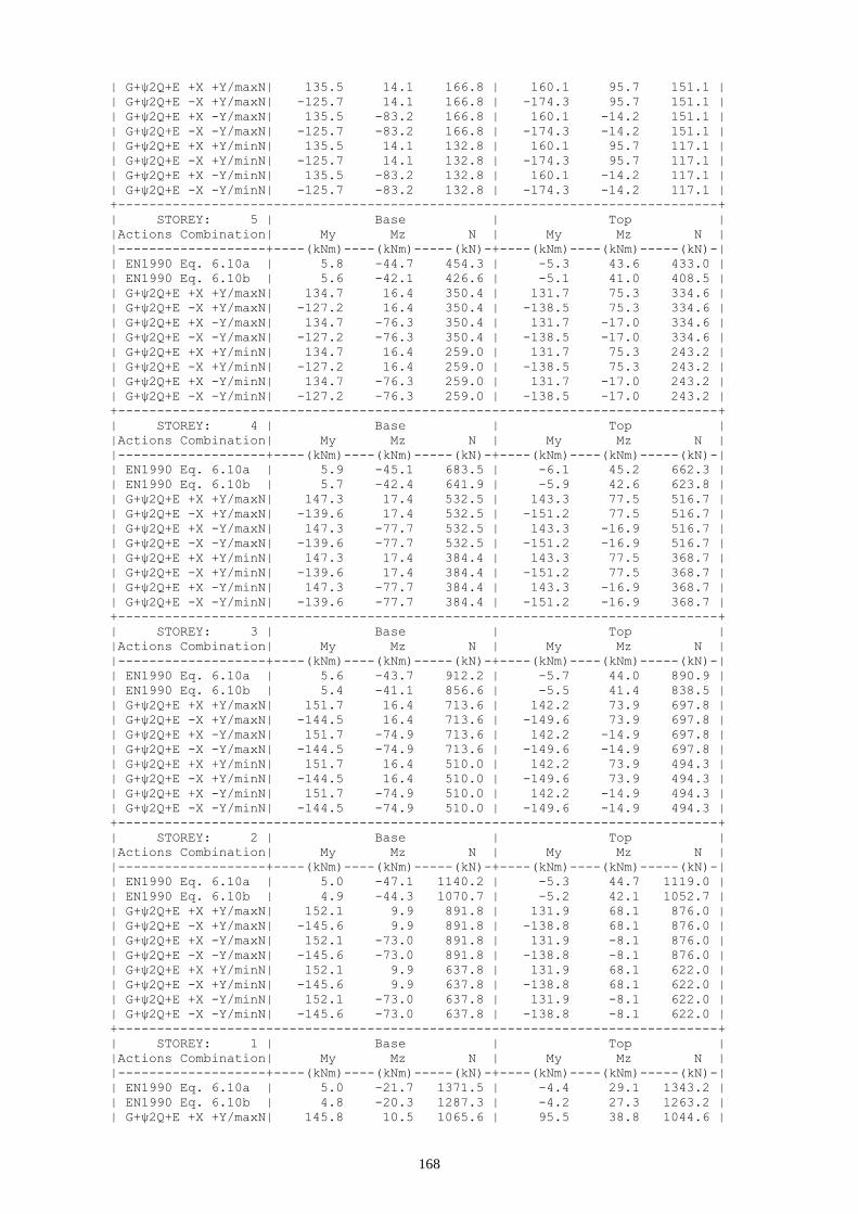
168
| G+ψ2Q+E +X +Y/maxN| 135.5 14.1 166.8 | 160.1 95.7 151.1 |
| G+ψ2Q+E -X +Y/maxN| -125.7 14.1 166.8 | -174.3 95.7 151.1 |
| G+ψ2Q+E +X -Y/maxN| 135.5 -83.2 166.8 | 160.1 -14.2 151.1 |
| G+ψ2Q+E -X -Y/maxN| -125.7 -83.2 166.8 | -174.3 -14.2 151.1 |
| G+ψ2Q+E +X +Y/minN| 135.5 14.1 132.8 | 160.1 95.7 117.1 |
| G+ψ2Q+E -X +Y/minN| -125.7 14.1 132.8 | -174.3 95.7 117.1 |
| G+ψ2Q+E +X -Y/minN| 135.5 -83.2 132.8 | 160.1 -14.2 117.1 |
| G+ψ2Q+E -X -Y/minN| -125.7 -83.2 132.8 | -174.3 -14.2 117.1 |
+-----------------------------------------------------------------------------+
| STOREY: 5 | Base | Top |
|Actions Combination| My Mz N | My Mz N |
|-------------------+----(kNm)----(kNm)-----(kN)-+----(kNm)----(kNm)-----(kN)-|
| EN1990 Eq. 6.10a | 5.8 -44.7 454.3 | -5.3 43.6 433.0 |
| EN1990 Eq. 6.10b | 5.6 -42.1 426.6 | -5.1 41.0 408.5 |
| G+ψ2Q+E +X +Y/maxN| 134.7 16.4 350.4 | 131.7 75.3 334.6 |
| G+ψ2Q+E -X +Y/maxN| -127.2 16.4 350.4 | -138.5 75.3 334.6 |
| G+ψ2Q+E +X -Y/maxN| 134.7 -76.3 350.4 | 131.7 -17.0 334.6 |
| G+ψ2Q+E -X -Y/maxN| -127.2 -76.3 350.4 | -138.5 -17.0 334.6 |
| G+ψ2Q+E +X +Y/minN| 134.7 16.4 259.0 | 131.7 75.3 243.2 |
| G+ψ2Q+E -X +Y/minN| -127.2 16.4 259.0 | -138.5 75.3 243.2 |
| G+ψ2Q+E +X -Y/minN| 134.7 -76.3 259.0 | 131.7 -17.0 243.2 |
| G+ψ2Q+E -X -Y/minN| -127.2 -76.3 259.0 | -138.5 -17.0 243.2 |
+-----------------------------------------------------------------------------+
| STOREY: 4 | Base | Top |
|Actions Combination| My Mz N | My Mz N |
|-------------------+----(kNm)----(kNm)-----(kN)-+----(kNm)----(kNm)-----(kN)-|
| EN1990 Eq. 6.10a | 5.9 -45.1 683.5 | -6.1 45.2 662.3 |
| EN1990 Eq. 6.10b | 5.7 -42.4 641.9 | -5.9 42.6 623.8 |
| G+ψ2Q+E +X +Y/maxN| 147.3 17.4 532.5 | 143.3 77.5 516.7 |
| G+ψ2Q+E -X +Y/maxN| -139.6 17.4 532.5 | -151.2 77.5 516.7 |
| G+ψ2Q+E +X -Y/maxN| 147.3 -77.7 532.5 | 143.3 -16.9 516.7 |
| G+ψ2Q+E -X -Y/maxN| -139.6 -77.7 532.5 | -151.2 -16.9 516.7 |
| G+ψ2Q+E +X +Y/minN| 147.3 17.4 384.4 | 143.3 77.5 368.7 |
| G+ψ2Q+E -X +Y/minN| -139.6 17.4 384.4 | -151.2 77.5 368.7 |
| G+ψ2Q+E +X -Y/minN| 147.3 -77.7 384.4 | 143.3 -16.9 368.7 |
| G+ψ2Q+E -X -Y/minN| -139.6 -77.7 384.4 | -151.2 -16.9 368.7 |
+-----------------------------------------------------------------------------+
| STOREY: 3 | Base | Top |
|Actions Combination| My Mz N | My Mz N |
|-------------------+----(kNm)----(kNm)-----(kN)-+----(kNm)----(kNm)-----(kN)-|
| EN1990 Eq. 6.10a | 5.6 -43.7 912.2 | -5.7 44.0 890.9 |
| EN1990 Eq. 6.10b | 5.4 -41.1 856.6 | -5.5 41.4 838.5 |
| G+ψ2Q+E +X +Y/maxN| 151.7 16.4 713.6 | 142.2 73.9 697.8 |
| G+ψ2Q+E -X +Y/maxN| -144.5 16.4 713.6 | -149.6 73.9 697.8 |
| G+ψ2Q+E +X -Y/maxN| 151.7 -74.9 713.6 | 142.2 -14.9 697.8 |
| G+ψ2Q+E -X -Y/maxN| -144.5 -74.9 713.6 | -149.6 -14.9 697.8 |
| G+ψ2Q+E +X +Y/minN| 151.7 16.4 510.0 | 142.2 73.9 494.3 |
| G+ψ2Q+E -X +Y/minN| -144.5 16.4 510.0 | -149.6 73.9 494.3 |
| G+ψ2Q+E +X -Y/minN| 151.7 -74.9 510.0 | 142.2 -14.9 494.3 |
| G+ψ2Q+E -X -Y/minN| -144.5 -74.9 510.0 | -149.6 -14.9 494.3 |
+-----------------------------------------------------------------------------+
| STOREY: 2 | Base | Top |
|Actions Combination| My Mz N | My Mz N |
|-------------------+----(kNm)----(kNm)-----(kN)-+----(kNm)----(kNm)-----(kN)-|
| EN1990 Eq. 6.10a | 5.0 -47.1 1140.2 | -5.3 44.7 1119.0 |
| EN1990 Eq. 6.10b | 4.9 -44.3 1070.7 | -5.2 42.1 1052.7 |
| G+ψ2Q+E +X +Y/maxN| 152.1 9.9 891.8 | 131.9 68.1 876.0 |
| G+ψ2Q+E -X +Y/maxN| -145.6 9.9 891.8 | -138.8 68.1 876.0 |
| G+ψ2Q+E +X -Y/maxN| 152.1 -73.0 891.8 | 131.9 -8.1 876.0 |
| G+ψ2Q+E -X -Y/maxN| -145.6 -73.0 891.8 | -138.8 -8.1 876.0 |
| G+ψ2Q+E +X +Y/minN| 152.1 9.9 637.8 | 131.9 68.1 622.0 |
| G+ψ2Q+E -X +Y/minN| -145.6 9.9 637.8 | -138.8 68.1 622.0 |
| G+ψ2Q+E +X -Y/minN| 152.1 -73.0 637.8 | 131.9 -8.1 622.0 |
| G+ψ2Q+E -X -Y/minN| -145.6 -73.0 637.8 | -138.8 -8.1 622.0 |
+-----------------------------------------------------------------------------+
| STOREY: 1 | Base | Top |
|Actions Combination| My Mz N | My Mz N |
|-------------------+----(kNm)----(kNm)-----(kN)-+----(kNm)----(kNm)-----(kN)-|
| EN1990 Eq. 6.10a | 5.0 -21.7 1371.5 | -4.4 29.1 1343.2 |
| EN1990 Eq. 6.10b | 4.8 -20.3 1287.3 | -4.2 27.3 1263.2 |
| G+ψ2Q+E +X +Y/maxN| 145.8 10.5 1065.6 | 95.5 38.8 1044.6 |
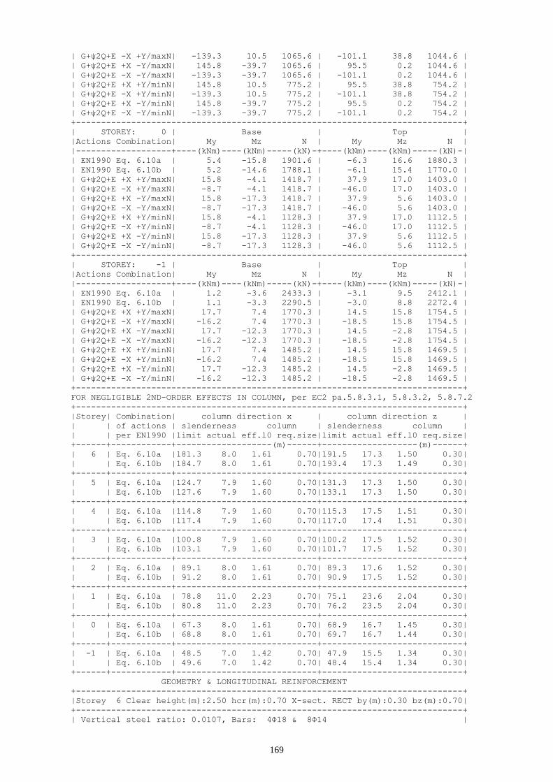
169
| G+ψ2Q+E -X +Y/maxN| -139.3 10.5 1065.6 | -101.1 38.8 1044.6 |
| G+ψ2Q+E +X -Y/maxN| 145.8 -39.7 1065.6 | 95.5 0.2 1044.6 |
| G+ψ2Q+E -X -Y/maxN| -139.3 -39.7 1065.6 | -101.1 0.2 1044.6 |
| G+ψ2Q+E +X +Y/minN| 145.8 10.5 775.2 | 95.5 38.8 754.2 |
| G+ψ2Q+E -X +Y/minN| -139.3 10.5 775.2 | -101.1 38.8 754.2 |
| G+ψ2Q+E +X -Y/minN| 145.8 -39.7 775.2 | 95.5 0.2 754.2 |
| G+ψ2Q+E -X -Y/minN| -139.3 -39.7 775.2 | -101.1 0.2 754.2 |
+-----------------------------------------------------------------------------+
| STOREY: 0 | Base | Top |
|Actions Combination| My Mz N | My Mz N |
|-------------------+----(kNm)----(kNm)-----(kN)-+----(kNm)----(kNm)-----(kN)-|
| EN1990 Eq. 6.10a | 5.4 -15.8 1901.6 | -6.3 16.6 1880.3 |
| EN1990 Eq. 6.10b | 5.2 -14.6 1788.1 | -6.1 15.4 1770.0 |
| G+ψ2Q+E +X +Y/maxN| 15.8 -4.1 1418.7 | 37.9 17.0 1403.0 |
| G+ψ2Q+E -X +Y/maxN| -8.7 -4.1 1418.7 | -46.0 17.0 1403.0 |
| G+ψ2Q+E +X -Y/maxN| 15.8 -17.3 1418.7 | 37.9 5.6 1403.0 |
| G+ψ2Q+E -X -Y/maxN| -8.7 -17.3 1418.7 | -46.0 5.6 1403.0 |
| G+ψ2Q+E +X +Y/minN| 15.8 -4.1 1128.3 | 37.9 17.0 1112.5 |
| G+ψ2Q+E -X +Y/minN| -8.7 -4.1 1128.3 | -46.0 17.0 1112.5 |
| G+ψ2Q+E +X -Y/minN| 15.8 -17.3 1128.3 | 37.9 5.6 1112.5 |
| G+ψ2Q+E -X -Y/minN| -8.7 -17.3 1128.3 | -46.0 5.6 1112.5 |
+-----------------------------------------------------------------------------+
| STOREY: -1 | Base | Top |
|Actions Combination| My Mz N | My Mz N |
|-------------------+----(kNm)----(kNm)-----(kN)-+----(kNm)----(kNm)-----(kN)-|
| EN1990 Eq. 6.10a | 1.2 -3.6 2433.3 | -3.1 9.5 2412.1 |
| EN1990 Eq. 6.10b | 1.1 -3.3 2290.5 | -3.0 8.8 2272.4 |
| G+ψ2Q+E +X +Y/maxN| 17.7 7.4 1770.3 | 14.5 15.8 1754.5 |
| G+ψ2Q+E -X +Y/maxN| -16.2 7.4 1770.3 | -18.5 15.8 1754.5 |
| G+ψ2Q+E +X -Y/maxN| 17.7 -12.3 1770.3 | 14.5 -2.8 1754.5 |
| G+ψ2Q+E -X -Y/maxN| -16.2 -12.3 1770.3 | -18.5 -2.8 1754.5 |
| G+ψ2Q+E +X +Y/minN| 17.7 7.4 1485.2 | 14.5 15.8 1469.5 |
| G+ψ2Q+E -X +Y/minN| -16.2 7.4 1485.2 | -18.5 15.8 1469.5 |
| G+ψ2Q+E +X -Y/minN| 17.7 -12.3 1485.2 | 14.5 -2.8 1469.5 |
| G+ψ2Q+E -X -Y/minN| -16.2 -12.3 1485.2 | -18.5 -2.8 1469.5 |
+-----------------------------------------------------------------------------+
FOR NEGLIGIBLE 2ND-ORDER EFFECTS IN COLUMN, per EC2 pa.5.8.3.1, 5.8.3.2, 5.8.7.2
+-----------------------------------------------------------------------------+
|Storey| Combination| column direction x | column direction z |
| | of actions | slenderness column | slenderness column |
| | per EN1990 |limit actual eff.l0 req.size|limit actual eff.l0 req.size|
+------+------------+-------------------(m)------+-------------------(m)------+
| 6 | Eq. 6.10a |181.3 8.0 1.61 0.70|191.5 17.3 1.50 0.30|
| | Eq. 6.10b |184.7 8.0 1.61 0.70|193.4 17.3 1.49 0.30|
+------+------------+----------------------------+----------------------------+
| 5 | Eq. 6.10a |124.7 7.9 1.60 0.70|131.3 17.3 1.50 0.30|
| | Eq. 6.10b |127.6 7.9 1.60 0.70|133.1 17.3 1.50 0.30|
+------+------------+----------------------------+----------------------------+
| 4 | Eq. 6.10a |114.8 7.9 1.60 0.70|115.3 17.5 1.51 0.30|
| | Eq. 6.10b |117.4 7.9 1.60 0.70|117.0 17.4 1.51 0.30|
+------+------------+----------------------------+----------------------------+
| 3 | Eq. 6.10a |100.8 7.9 1.60 0.70|100.2 17.5 1.52 0.30|
| | Eq. 6.10b |103.1 7.9 1.60 0.70|101.7 17.5 1.52 0.30|
+------+------------+----------------------------+----------------------------+
| 2 | Eq. 6.10a | 89.1 8.0 1.61 0.70| 89.3 17.6 1.52 0.30|
| | Eq. 6.10b | 91.2 8.0 1.61 0.70| 90.9 17.5 1.52 0.30|
+------+------------+----------------------------+----------------------------+
| 1 | Eq. 6.10a | 78.8 11.0 2.23 0.70| 75.1 23.6 2.04 0.30|
| | Eq. 6.10b | 80.8 11.0 2.23 0.70| 76.2 23.5 2.04 0.30|
+------+------------+----------------------------+----------------------------+
| 0 | Eq. 6.10a | 67.3 8.0 1.61 0.70| 68.9 16.7 1.45 0.30|
| | Eq. 6.10b | 68.8 8.0 1.61 0.70| 69.7 16.7 1.44 0.30|
+------+------------+----------------------------+----------------------------+
| -1 | Eq. 6.10a | 48.5 7.0 1.42 0.70| 47.9 15.5 1.34 0.30|
| | Eq. 6.10b | 49.6 7.0 1.42 0.70| 48.4 15.4 1.34 0.30|
+------+------------+----------------------------+----------------------------+
GEOMETRY & LONGITUDINAL REINFORCEMENT
+-----------------------------------------------------------------------------+
|Storey 6 Clear height(m):2.50 hcr(m):0.70 X-sect. RECT by(m):0.30 bz(m):0.70|
+-----------------------------------------------------------------------------+
| Vertical steel ratio: 0.0107, Bars: 4Φ18 & 8Φ14 |

170
| 2Φ18 & 1Φ14 along by 2Φ18 & 3Φ14 along bz |
+-----------------------------------------------------------------------------+
|Storey 5 Clear height(m):2.50 hcr(m):0.70 X-sect. RECT by(m):0.30 bz(m):0.70|
+-----------------------------------------------------------------------------+
| Vertical steel ratio: 0.0107, Bars: 4Φ18 & 8Φ14 |
| 2Φ18 & 1Φ14 along by 2Φ18 & 3Φ14 along bz |
+-----------------------------------------------------------------------------+
|Storey 4 Clear height(m):2.50 hcr(m):0.70 X-sect. RECT by(m):0.30 bz(m):0.70|
+-----------------------------------------------------------------------------+
| Vertical steel ratio: 0.0107, Bars: 4Φ18 & 8Φ14 |
| 2Φ18 & 1Φ14 along by 2Φ18 & 3Φ14 along bz |
+-----------------------------------------------------------------------------+
|Storey 3 Clear height(m):2.50 hcr(m):0.70 X-sect. RECT by(m):0.30 bz(m):0.70|
+-----------------------------------------------------------------------------+
| Vertical steel ratio: 0.0107, Bars: 4Φ18 & 8Φ14 |
| 2Φ18 & 1Φ14 along by 2Φ18 & 3Φ14 along bz |
+-----------------------------------------------------------------------------+
|Storey 2 Clear height(m):2.50 hcr(m):0.70 X-sect. RECT by(m):0.30 bz(m):0.70|
+-----------------------------------------------------------------------------+
| Vertical steel ratio: 0.0107, Bars: 4Φ18 & 8Φ14 |
| 2Φ18 & 1Φ14 along by 2Φ18 & 3Φ14 along bz |
+-----------------------------------------------------------------------------+
|Storey 1 Clear height(m):3.50 hcr(m):0.70 X-sect. RECT by(m):0.30 bz(m):0.70|
+-----------------------------------------------------------------------------+
| Vertical steel ratio: 0.0107, Bars: 4Φ18 & 8Φ14 |
| 2Φ18 & 1Φ14 along by 2Φ18 & 3Φ14 along bz |
+-----------------------------------------------------------------------------+
|Storey 0 Clear height(m):2.50 hcr(m):0.70 X-sect. RECT by(m):0.30 bz(m):0.70|
+-----------------------------------------------------------------------------+
| Vertical steel ratio: 0.0107, Bars: 4Φ18 & 8Φ14 |
| 2Φ18 & 1Φ14 along by 2Φ18 & 3Φ14 along bz |
+-----------------------------------------------------------------------------+
|Storey -1 Clear height(m):2.50 hcr(m):0.70 X-sect. RECT by(m):0.30 bz(m):0.70|
+-----------------------------------------------------------------------------+
| Vertical steel ratio: 0.0107, Bars: 4Φ18 & 8Φ14 |
| 2Φ18 & 1Φ14 along by 2Φ18 & 3Φ14 along bz |
+-----------------------------------------------------------------------------+
|Starter bars at base: 4Φ18 & 8Φ14 |
| 2Φ18 & 1Φ14 along by 2Φ18 & 3Φ14 along bz |
+-----------------------------------------------------------------------------+
COLUMN DESIGN MOMENT RESISTANCE MRd,c (for minN/maxN)
+-----------------------------------------------------------------------------+
|Storey|Locat.| Direction of MRd Vector : |
| | | +y | -y | +z | -z |
+------+------+-----(kNm)-----+-----(kNm)-----+-----(kNm)-----+-----(kNm)-----+
| 6 | Top | 253.8/ 314.6| -253.8/ -314.6| 90.6/ 94.3| -90.6/ -94.3|
| | Base | 259.5/ 317.9| -259.5/ -317.9| 92.3/ 96.0| -92.3/ -96.0|
+-----------------------------------------------------------------------------+
| 5 | Top | 333.3/ 350.6| -333.3/ -350.6| 104.1/ 113.1| -104.1/ -113.1|
| | Base | 336.4/ 353.4| -336.4/ -353.4| 105.7/ 114.6| -105.7/ -114.6|
+-----------------------------------------------------------------------------+
| 4 | Top | 356.6/ 380.9| -356.6/ -380.9| 116.3/ 129.2| -116.3/ -129.2|
| | Base | 359.4/ 383.3| -359.4/ -383.3| 117.8/ 130.5| -117.8/ -130.5|
+-----------------------------------------------------------------------------+
| 3 | Top | 377.5/ 405.9| -377.5/ -405.9| 127.4/ 142.7| -127.4/ -142.7|
| | Base | 379.9/ 407.8| -379.9/ -407.8| 128.7/ 143.8| -128.7/ -143.8|
+-----------------------------------------------------------------------------+
| 2 | Top | 396.1/ 425.4| -396.1/ -425.4| 137.3/ 153.5| -137.3/ -153.5|
| | Base | 398.2/ 426.9| -398.2/ -426.9| 138.5/ 154.4| -138.5/ -154.4|
+-----------------------------------------------------------------------------+
| 1 | Top | 412.6/ 439.3| -412.6/ -439.3| 146.4/ 161.6| -146.4/ -161.6|
| | Base | 415.0/ 440.7| -415.0/ -440.7| 147.7/ 162.5| -147.7/ -162.5|
+-----------------------------------------------------------------------------+
| 0 | Top | 443.6/ 453.8| -443.6/ -453.8| 164.2/ 170.1| -164.2/ -170.1|
| | Base | 444.5/ 453.9| -444.5/ -453.9| 164.8/ 170.0| -164.8/ -170.0|
+-----------------------------------------------------------------------------+
| -1 | Top | 454.2/ 453.6| -454.2/ -453.6| 169.7/ 160.4| -169.7/ -160.4|
| | Base | 454.2/ 452.2| -454.2/ -452.2| 171.0/ 159.7| -171.0/ -159.7|
+-----------------------------------------------------------------------------+
SUM OF BEAM DESIGN MOMENT RESISTANCES, MRd,b, AROUND JOINT
+-----------------------------------------------------------------------------+

171
|Storey|Locat.| Direction of MRd Vector : |
| | | +y | -y | +z | -z |
+------+------+-----(kNm)-----+-----(kNm)-----+-----(kNm)-----+-----(kNm)-----+
| 6 | Top | 197.6| 197.6| 88.0| 126.7|
| | Base | 231.2| 231.2| 88.0| 145.3|
+-----------------------------------------------------------------------------+
| 5 | Top | 231.2| 231.2| 88.0| 145.3|
| | Base | 245.4| 273.9| 88.0| 145.3|
+-----------------------------------------------------------------------------+
| 4 | Top | 245.4| 273.9| 88.0| 145.3|
| | Base | 245.4| 273.9| 88.0| 133.5|
+-----------------------------------------------------------------------------+
| 3 | Top | 245.4| 273.9| 88.0| 133.5|
| | Base | 245.4| 273.9| 88.0| 145.3|
+-----------------------------------------------------------------------------+
| 2 | Top | 245.4| 273.9| 88.0| 145.3|
| | Base | 221.4| 221.4| 76.8| 156.5|
+-----------------------------------------------------------------------------+
| 1 | Top | 221.4| 221.4| 76.8| 156.5|
| | Base | 175.9| 175.9| 191.4| 191.5|
+-----------------------------------------------------------------------------+
| 0 | Top | 175.9| 175.9| 191.4| 191.5|
| | Base | 141.8| 141.8| 193.4| 193.6|
+-----------------------------------------------------------------------------+
| -1 | Top | 141.8| 141.8| 193.4| 193.6|
| | Base | 0.0| 0.0| 0.0| 0.0|
+-----------------------------------------------------------------------------+
DESIGN OF TRANSVERSE REINFORCEMENT IN SHEAR (for maxN/minN)
+-----------------------------------------------------------------------------+
| Storey |Des. Shear| Provided Ties |strut angle| VR,s | VR,max |
| | VEd (kN)| dia. legs spacing-s| (deg) |(middle-kN)|(middle-kN)|
| | y z |(mm) y z middle-mm| y z | y z | y z |
+--------+----------+---------------------+-----------+-----------+-----------+
| 6 maxN| 87. 42.| 6 3.0 5.0 170 | 22 22| 358. 217.| 545. 490.|
| minN| 87. 40.| | 22 22| 346. 213.| 545. 490.|
+-----------------------------------------------------------------------------+
| 5 maxN| 54. 19.| 6 3.0 5.0 170 | 22 22| 402. 232.| 545. 490.|
| minN| 58. 18.| | 22 22| 376. 223.| 545. 490.|
+-----------------------------------------------------------------------------+
| 4 maxN| 63. 18.| 6 3.0 5.0 170 | 22 22| 446. 247.| 545. 490.|
| minN| 62. 18.| | 22 22| 406. 233.| 545. 490.|
+-----------------------------------------------------------------------------+
| 3 maxN| 62. 16.| 6 3.0 5.0 170 | 22 22| 489. 261.| 545. 490.|
| minN| 62. 16.| | 22 22| 436. 244.| 545. 490.|
+-----------------------------------------------------------------------------+
| 2 maxN| 62. 17.| 6 3.0 5.0 170 | 22 22| 532. 275.| 545. 490.|
| minN| 62. 17.| | 22 22| 467. 254.| 545. 490.|
+-----------------------------------------------------------------------------+
| 1 maxN| 35. 13.| 6 3.0 5.0 170 | 22 22| 500. 265.| 545. 490.|
| minN| 36. 13.| | 22 22| 447. 247.| 545. 490.|
+-----------------------------------------------------------------------------+
| 0 maxN| 21. 11.| 6 3.0 5.0 170 | 25 22| 607. 318.| 615. 490.|
| minN| 21. 11.| | 23 22| 567. 293.| 568. 490.|
+-----------------------------------------------------------------------------+
| -1 maxN| 12. 9.| 6 3.0 5.0 170 | 28 22| 661. 346.| 661. 490.|
| minN| 12. 9.| | 26 22| 616. 322.| 620. 490.|
+-----------------------------------------------------------------------------+
CONFINEMENT REINFORCEMENT AT COLUMN ENDS (for maxN/minN)
+-----------------------------------------------------------------------------+
|Story| Wwd-req. | aWwd-req. | Stirrups | Wwd-prov. | aWwd-prov. |
| | base top | base top |dia. legs spacing-mm| base top | base top |
| | | |(mm) y z base top| | |
+-----+----------+-----------+----------------------+------------+------------+
| 6 | 0.00 0.00|0.000 0.000| 6 3.0 5.0 110 110| 0.174 0.174| 0.055 0.055|
+-----------------------------------------------------------------------------+
| 5 | 0.00 0.00|0.000 0.000| 6 3.0 5.0 110 110| 0.174 0.174| 0.055 0.055|
+-----------------------------------------------------------------------------+
| 4 | 0.00 0.00|0.000 0.000| 6 3.0 5.0 110 110| 0.174 0.174| 0.055 0.055|
+-----------------------------------------------------------------------------+
| 3 | 0.00 0.00|0.000 0.000| 6 3.0 5.0 110 110| 0.174 0.174| 0.055 0.055|
+-----------------------------------------------------------------------------+

172
| 2 | 0.00 0.00|0.000 0.000| 6 3.0 5.0 110 110| 0.174 0.174| 0.055 0.055|
+-----------------------------------------------------------------------------+
| 1 | 0.08 0.00|0.117 0.000| 8 3.0 5.0 100 110| 0.341 0.310| 0.114 0.098|
+-----------------------------------------------------------------------------+
| 0 | 0.00 0.00|0.000 0.000| 6 3.0 5.0 170 170| 0.113 0.113| 0.025 0.025|
+-----------------------------------------------------------------------------+
| -1 | 0.00 0.00|0.000 0.000| 6 3.0 5.0 170 170| 0.113 0.113| 0.025 0.025|
+-----------------------------------------------------------------------------+
STOREY: 0 CAPACITY DESIGN FACTOR FOR FOUNDATION
+-----------------------------------------------------------------------------+
|Actions Combination| MRd,y | MEd,y | aCD,y| MRd,z | MEd,z | aCD,z| acD |
|-------------------+--(kNm)-+--(kNm)-+------+--(kNm)-+--(kNm)-+------+-------|
| G+ψ2Q+E +X +Y/maxN| 440.7| 145.8| 3.63| 162.5| 10.5| 15.45| 3.000|
| G+ψ2Q+E -X +Y/maxN| 440.7| 139.3| 3.80| 162.5| 10.5| 15.45| 3.000|
| G+ψ2Q+E +X -Y/maxN| 440.7| 145.8| 3.63| 162.5| 39.7| 4.09| 3.000|
| G+ψ2Q+E -X -Y/maxN| 440.7| 139.3| 3.80| 162.5| 39.7| 4.09| 3.000|
| G+ψ2Q+E +X +Y/minN| 415.0| 145.8| 3.42| 147.7| 10.5| 14.05| 3.000|
| G+ψ2Q+E -X +Y/minN| 415.0| 139.3| 3.57| 147.7| 10.5| 14.05| 3.000|
| G+ψ2Q+E +X -Y/minN| 415.0| 145.8| 3.42| 147.7| 39.7| 3.72| 3.000|
| G+ψ2Q+E -X -Y/minN| 415.0| 139.3| 3.57| 147.7| 39.7| 3.72| 3.000|
+-----------------------------------------------------------------------------+

173
Fig. 7.1 Cross-section of columns C1, C6, C11 and C16 (longitudinal reinforcement 4Φ18 &
6Φ14)
Fig. 7.2 Cross-section of columns C2 to C5 and C12 to C15 (longitudinal reinforcement 4Φ18 &
8Φ14)
Fig. 7.3 Cross-section of columns C7, C8, C9 and C10 (longitudinal reinforcement 4Φ18 & 8Φ14)


175
8 Design of beams in shear
8.1 Frame A
+-----------------------------------------------------------------------------+
SHEAR FORCES - ULS DESIGN OF TRANSVERSE REINFORCEMENT
+-----------------------------------------------------------------------------+
* Concrete: C25 - Long. Reinforcement: S500 - Stirrups: S500 - Cover: 35(mm) *
*-----------------------------------------------------------------------------*
STOREY: 6 * BEAMS: 1 2 3 4 5
*-----------------------------------------------------------------------------*
SUM OF BEAM/COLUMN DESIGN MOMENT RESISTANCES, SMRd,b/SMRd,c, AROUND JOINT
+-----------------------------------------------------------------------------+
| Beam| Beam end & direction of MRd Vector: |
| | Left End +y | Left End -y | Right End +y | Right End -y |
+-----+------(kNm)------+------(kNm)------+------(kNm)------+------(kNm)------+
*-----------------------------------------------------------------------------*
| 1 | 100.7 / 78.9 | 87.2 / 78.9 | 197.6 / 353.9 | 197.6 / 353.9 |
| 2 | 197.6 / 353.9 | 197.6 / 353.9 | 197.6 / 315.0 | 197.6 / 315.0 |
| 3 | 197.6 / 315.0 | 197.6 / 315.0 | 197.6 / 315.0 | 197.6 / 315.0 |
| 4 | 197.6 / 315.0 | 197.6 / 315.0 | 197.6 / 353.9 | 197.6 / 353.9 |
| 5 | 197.6 / 353.9 | 197.6 / 353.9 | 87.2 / 78.9 | 100.7 / 78.9 |
+-----------------------------------------------------------------------------+
|Beam: 1 |
| Seismic Shear (kN)- L End: maxVEd: 58.9 minVEd: -5.8 minV/maxV:-0.10|
| Seismic Shear (kN)- R End: maxVEd: 72.5 minVEd: 7.9 minV/maxV: 0.11|
|-----------------------------------------------------------------------------|
|Region|Length|Ties design shear|max tie|Prov. ties | strut | VR,s | VR,max |
| | |Seismic Non-Seis.|spacing| No. Φ s | angle |provided|provided|
|------+-(m)--+------(kN)-------+-(mm)--+-----(mm)--+-(deg)-+--(kN)--+--(kN)--|
|L End | 0.50| 52.8 37.6| 96 | 7 8 95 | 23 | 434.9 | 434.9 |
|Centre| 4.50| 60.3 35.7| 330 | 15 8 330 | 22 | 133.2 | 416.2 |
|R End | 0.50| 66.4 44.8| 96 | 7 8 95 | 23 | 434.9 | 434.9 |
+-----------------------------------------------------------------------------+
|Beam: 2 |
| Seismic Shear (kN)- L End: maxVEd: 66.8 minVEd: -7.8 minV/maxV:-0.12|
| Seismic Shear (kN)- R End: maxVEd: 72.1 minVEd: -2.5 minV/maxV:-0.03|
|-----------------------------------------------------------------------------|
|Region|Length|Ties design shear|max tie|Prov. ties | strut | VR,s | VR,max |
| | |Seismic Non-Seis.|spacing| No. Φ s | angle |provided|provided|
|------+-(m)--+------(kN)-------+-(mm)--+-----(mm)--+-(deg)-+--(kN)--+--(kN)--|
|L End | 0.50| 60.9 37.7| 96 | 7 8 95 | 23 | 434.9 | 434.9 |
|Centre| 4.30| 60.4 32.9| 330 | 15 8 330 | 22 | 133.2 | 416.2 |
|R End | 0.50| 66.2 41.7| 96 | 7 8 95 | 23 | 434.9 | 434.9 |
+-----------------------------------------------------------------------------+
|Beam: 3 |
| Seismic Shear (kN)- L End: maxVEd: 69.4 minVEd: -5.1 minV/maxV:-0.07|
| Seismic Shear (kN)- R End: maxVEd: 69.4 minVEd: -5.1 minV/maxV:-0.07|
|-----------------------------------------------------------------------------|
|Region|Length|Ties design shear|max tie|Prov. ties | strut | VR,s | VR,max |
| | |Seismic Non-Seis.|spacing| No. Φ s | angle |provided|provided|
|------+-(m)--+------(kN)-------+-(mm)--+-----(mm)--+-(deg)-+--(kN)--+--(kN)--|
|L End | 0.50| 63.6 39.7| 96 | 7 8 95 | 23 | 434.9 | 434.9 |
|Centre| 4.30| 57.8 30.9| 330 | 15 8 330 | 22 | 133.2 | 416.2 |
|R End | 0.50| 63.6 39.7| 96 | 7 8 95 | 23 | 434.9 | 434.9 |
+-----------------------------------------------------------------------------+
|Beam: 4 |
| Seismic Shear (kN)- L End: maxVEd: 72.2 minVEd: -2.4 minV/maxV:-0.03|
| Seismic Shear (kN)- R End: maxVEd: 66.7 minVEd: -7.9 minV/maxV:-0.12|
|-----------------------------------------------------------------------------|
|Region|Length|Ties design shear|max tie|Prov. ties | strut | VR,s | VR,max |
| | |Seismic Non-Seis.|spacing| No. Φ s | angle |provided|provided|
|------+-(m)--+------(kN)-------+-(mm)--+-----(mm)--+-(deg)-+--(kN)--+--(kN)--|
|L End | 0.50| 66.3 41.8| 96 | 7 8 95 | 23 | 434.9 | 434.9 |
|Centre| 4.30| 60.5 32.9| 330 | 15 8 330 | 22 | 133.2 | 416.2 |
|R End | 0.50| 60.9 37.6| 96 | 7 8 95 | 23 | 434.9 | 434.9 |
+-----------------------------------------------------------------------------+
|Beam: 5 |
| Seismic Shear (kN)- L End: maxVEd: 72.5 minVEd: 7.9 minV/maxV: 0.11|
| Seismic Shear (kN)- R End: maxVEd: 58.8 minVEd: -5.8 minV/maxV:-0.10|

176
|-----------------------------------------------------------------------------|
|Region|Length|Ties design shear|max tie|Prov. ties | strut | VR,s | VR,max |
| | |Seismic Non-Seis.|spacing| No. Φ s | angle |provided|provided|
|------+-(m)--+------(kN)-------+-(mm)--+-----(mm)--+-(deg)-+--(kN)--+--(kN)--|
|L End | 0.50| 66.4 44.8| 96 | 7 8 95 | 23 | 434.9 | 434.9 |
|Centre| 4.50| 60.4 35.7| 330 | 15 8 330 | 22 | 133.2 | 416.2 |
|R End | 0.50| 52.8 37.6| 96 | 7 8 95 | 23 | 434.9 | 434.9 |
+-----------------------------------------------------------------------------+
*-----------------------------------------------------------------------------*
STOREY: 5 * BEAMS: 1 2 3 4 5
*-----------------------------------------------------------------------------*
SUM OF BEAM/COLUMN DESIGN MOMENT RESISTANCES, SMRd,b/SMRd,c, AROUND JOINT
+-----------------------------------------------------------------------------+
| Beam| Beam end & direction of MRd Vector: |
| | Left End +y | Left End -y | Right End +y | Right End -y |
+-----+------(kNm)------+------(kNm)------+------(kNm)------+------(kNm)------+
*-----------------------------------------------------------------------------*
| 1 | 107.8 / 177.3 | 87.2 / 177.3 | 245.4 / 690.4 | 241.0 / 690.4 |
| 2 | 245.4 / 690.4 | 241.0 / 690.4 | 245.4 / 670.0 | 273.9 / 670.0 |
| 3 | 245.4 / 670.0 | 273.9 / 670.0 | 273.9 / 670.0 | 245.4 / 670.0 |
| 4 | 273.9 / 670.0 | 245.4 / 670.0 | 241.0 / 690.4 | 245.4 / 690.4 |
| 5 | 241.0 / 690.4 | 245.4 / 690.4 | 87.2 / 177.3 | 107.8 / 177.3 |
+-----------------------------------------------------------------------------+
|Beam: 1 |
| Seismic Shear (kN)- L End: maxVEd: 69.7 minVEd: -4.4 minV/maxV:-0.06|
| Seismic Shear (kN)- R End: maxVEd: 71.1 minVEd: -3.0 minV/maxV:-0.04|
|-----------------------------------------------------------------------------|
|Region|Length|Ties design shear|max tie|Prov. ties | strut | VR,s | VR,max |
| | |Seismic Non-Seis.|spacing| No. Φ s | angle |provided|provided|
|------+-(m)--+------(kN)-------+-(mm)--+-----(mm)--+-(deg)-+--(kN)--+--(kN)--|
|L End | 0.50| 63.7 41.8| 112 | 6 8 110 | 22 | 399.6 | 416.2 |
|Centre| 4.50| 59.0 32.7| 330 | 15 8 330 | 22 | 133.2 | 416.2 |
|R End | 0.50| 65.0 40.6| 112 | 6 8 110 | 22 | 399.6 | 416.2 |
+-----------------------------------------------------------------------------+
|Beam: 2 |
| Seismic Shear (kN)- L End: maxVEd: 74.4 minVEd: -23.6 minV/maxV:-0.32|
| Seismic Shear (kN)- R End: maxVEd: 87.9 minVEd: -10.1 minV/maxV:-0.12|
|-----------------------------------------------------------------------------|
|Region|Length|Ties design shear|max tie|Prov. ties | strut | VR,s | VR,max |
| | |Seismic Non-Seis.|spacing| No. Φ s | angle |provided|provided|
|------+-(m)--+------(kN)-------+-(mm)--+-----(mm)--+-(deg)-+--(kN)--+--(kN)--|
|L End | 0.50| 68.6 36.6| 112 | 6 8 110 | 22 | 399.6 | 416.2 |
|Centre| 4.30| 76.2 33.9| 330 | 15 8 330 | 22 | 133.2 | 416.2 |
|R End | 0.50| 82.0 42.8| 112 | 6 8 110 | 22 | 399.6 | 416.2 |
+-----------------------------------------------------------------------------+
|Beam: 3 |
| Seismic Shear (kN)- L End: maxVEd: 83.8 minVEd: -19.5 minV/maxV:-0.23|
| Seismic Shear (kN)- R End: maxVEd: 83.8 minVEd: -19.5 minV/maxV:-0.23|
|-----------------------------------------------------------------------------|
|Region|Length|Ties design shear|max tie|Prov. ties | strut | VR,s | VR,max |
| | |Seismic Non-Seis.|spacing| No. Φ s | angle |provided|provided|
|------+-(m)--+------(kN)-------+-(mm)--+-----(mm)--+-(deg)-+--(kN)--+--(kN)--|
|L End | 0.50| 78.0 39.7| 112 | 6 8 110 | 22 | 399.6 | 416.2 |
|Centre| 4.30| 72.1 30.9| 330 | 15 8 330 | 22 | 133.2 | 416.2 |
|R End | 0.50| 78.0 39.7| 112 | 6 8 110 | 22 | 399.6 | 416.2 |
+-----------------------------------------------------------------------------+
|Beam: 4 |
| Seismic Shear (kN)- L End: maxVEd: 88.0 minVEd: -10.0 minV/maxV:-0.11|
| Seismic Shear (kN)- R End: maxVEd: 74.3 minVEd: -23.7 minV/maxV:-0.32|
|-----------------------------------------------------------------------------|
|Region|Length|Ties design shear|max tie|Prov. ties | strut | VR,s | VR,max |
| | |Seismic Non-Seis.|spacing| No. Φ s | angle |provided|provided|
|------+-(m)--+------(kN)-------+-(mm)--+-----(mm)--+-(deg)-+--(kN)--+--(kN)--|
|L End | 0.50| 82.1 42.8| 112 | 6 8 110 | 22 | 399.6 | 416.2 |
|Centre| 4.30| 76.3 34.0| 330 | 15 8 330 | 22 | 133.2 | 416.2 |
|R End | 0.50| 68.5 36.6| 112 | 6 8 110 | 22 | 399.6 | 416.2 |
+-----------------------------------------------------------------------------+
|Beam: 5 |
| Seismic Shear (kN)- L End: maxVEd: 71.1 minVEd: -3.0 minV/maxV:-0.04|
| Seismic Shear (kN)- R End: maxVEd: 69.7 minVEd: -4.4 minV/maxV:-0.06|
|-----------------------------------------------------------------------------|

177
|Region|Length|Ties design shear|max tie|Prov. ties | strut | VR,s | VR,max |
| | |Seismic Non-Seis.|spacing| No. Φ s | angle |provided|provided|
|------+-(m)--+------(kN)-------+-(mm)--+-----(mm)--+-(deg)-+--(kN)--+--(kN)--|
|L End | 0.50| 65.1 40.6| 112 | 6 8 110 | 22 | 399.6 | 416.2 |
|Centre| 4.50| 59.0 32.6| 330 | 15 8 330 | 22 | 133.2 | 416.2 |
|R End | 0.50| 63.6 41.8| 112 | 6 8 110 | 22 | 399.6 | 416.2 |
+-----------------------------------------------------------------------------+
*-----------------------------------------------------------------------------*
STOREY: 4 * BEAMS: 1 2 3 4 5
*-----------------------------------------------------------------------------*
SUM OF BEAM/COLUMN DESIGN MOMENT RESISTANCES, SMRd,b/SMRd,c, AROUND JOINT
+-----------------------------------------------------------------------------+
| Beam| Beam end & direction of MRd Vector: |
| | Left End +y | Left End -y | Right End +y | Right End -y |
+-----+------(kNm)------+------(kNm)------+------(kNm)------+------(kNm)------+
*-----------------------------------------------------------------------------*
| 1 | 120.1 / 210.0 | 87.2 / 210.0 | 262.3 / 765.5 | 249.9 / 765.5 |
| 2 | 262.3 / 765.5 | 249.9 / 765.5 | 303.1 / 737.1 | 303.1 / 737.1 |
| 3 | 303.1 / 737.1 | 303.1 / 737.1 | 303.1 / 737.1 | 303.1 / 737.1 |
| 4 | 303.1 / 737.1 | 303.1 / 737.1 | 249.9 / 765.5 | 262.3 / 765.5 |
| 5 | 249.9 / 765.5 | 262.3 / 765.5 | 87.2 / 210.0 | 120.1 / 210.0 |
+-----------------------------------------------------------------------------+
|Beam: 1 |
| Seismic Shear (kN)- L End: maxVEd: 70.6 minVEd: -7.3 minV/maxV:-0.10|
| Seismic Shear (kN)- R End: maxVEd: 74.0 minVEd: -3.9 minV/maxV:-0.05|
|-----------------------------------------------------------------------------|
|Region|Length|Ties design shear|max tie|Prov. ties | strut | VR,s | VR,max |
| | |Seismic Non-Seis.|spacing| No. Φ s | angle |provided|provided|
|------+-(m)--+------(kN)-------+-(mm)--+-----(mm)--+-(deg)-+--(kN)--+--(kN)--|
|L End | 0.50| 64.6 40.8| 96 | 7 8 95 | 23 | 434.9 | 434.9 |
|Centre| 4.50| 61.9 32.4| 330 | 15 8 330 | 22 | 133.2 | 416.2 |
|R End | 0.50| 67.9 41.6| 112 | 6 8 110 | 23 | 399.6 | 416.2 |
+-----------------------------------------------------------------------------+
|Beam: 2 |
| Seismic Shear (kN)- L End: maxVEd: 89.2 minVEd: -22.9 minV/maxV:-0.26|
| Seismic Shear (kN)- R End: maxVEd: 87.2 minVEd: -24.9 minV/maxV:-0.29|
|-----------------------------------------------------------------------------|
|Region|Length|Ties design shear|max tie|Prov. ties | strut | VR,s | VR,max |
| | |Seismic Non-Seis.|spacing| No. Φ s | angle |provided|provided|
|------+-(m)--+------(kN)-------+-(mm)--+-----(mm)--+-(deg)-+--(kN)--+--(kN)--|
|L End | 0.50| 83.3 37.2| 112 | 6 8 110 | 22 | 399.6 | 416.2 |
|Centre| 4.30| 77.5 33.4| 330 | 15 8 330 | 22 | 133.2 | 416.2 |
|R End | 0.50| 81.3 42.2| 112 | 6 8 110 | 22 | 399.6 | 416.2 |
+-----------------------------------------------------------------------------+
|Beam: 3 |
| Seismic Shear (kN)- L End: maxVEd: 89.3 minVEd: -25.0 minV/maxV:-0.28|
| Seismic Shear (kN)- R End: maxVEd: 89.3 minVEd: -25.1 minV/maxV:-0.28|
|-----------------------------------------------------------------------------|
|Region|Length|Ties design shear|max tie|Prov. ties | strut | VR,s | VR,max |
| | |Seismic Non-Seis.|spacing| No. Φ s | angle |provided|provided|
|------+-(m)--+------(kN)-------+-(mm)--+-----(mm)--+-(deg)-+--(kN)--+--(kN)--|
|L End | 0.50| 83.5 39.7| 112 | 6 8 110 | 22 | 399.6 | 416.2 |
|Centre| 4.30| 77.6 30.9| 330 | 15 8 330 | 22 | 133.2 | 416.2 |
|R End | 0.50| 83.5 39.7| 112 | 6 8 110 | 22 | 399.6 | 416.2 |
+-----------------------------------------------------------------------------+
|Beam: 4 |
| Seismic Shear (kN)- L End: maxVEd: 87.2 minVEd: -24.8 minV/maxV:-0.28|
| Seismic Shear (kN)- R End: maxVEd: 89.1 minVEd: -22.9 minV/maxV:-0.26|
|-----------------------------------------------------------------------------|
|Region|Length|Ties design shear|max tie|Prov. ties | strut | VR,s | VR,max |
| | |Seismic Non-Seis.|spacing| No. Φ s | angle |provided|provided|
|------+-(m)--+------(kN)-------+-(mm)--+-----(mm)--+-(deg)-+--(kN)--+--(kN)--|
|L End | 0.50| 81.4 42.3| 112 | 6 8 110 | 22 | 399.6 | 416.2 |
|Centre| 4.30| 77.4 33.4| 330 | 15 8 330 | 22 | 133.2 | 416.2 |
|R End | 0.50| 83.3 37.1| 112 | 6 8 110 | 22 | 399.6 | 416.2 |
+-----------------------------------------------------------------------------+
|Beam: 5 |
| Seismic Shear (kN)- L End: maxVEd: 74.0 minVEd: -3.9 minV/maxV:-0.05|
| Seismic Shear (kN)- R End: maxVEd: 70.6 minVEd: -7.3 minV/maxV:-0.10|
|-----------------------------------------------------------------------------|
|Region|Length|Ties design shear|max tie|Prov. ties | strut | VR,s | VR,max |

178
| | |Seismic Non-Seis.|spacing| No. Φ s | angle |provided|provided|
|------+-(m)--+------(kN)-------+-(mm)--+-----(mm)--+-(deg)-+--(kN)--+--(kN)--|
|L End | 0.50| 68.0 41.6| 112 | 6 8 110 | 22 | 399.6 | 416.2 |
|Centre| 4.50| 61.9 32.4| 330 | 15 8 330 | 22 | 133.2 | 416.2 |
|R End | 0.50| 64.5 40.8| 96 | 7 8 95 | 22 | 434.9 | 434.9 |
+-----------------------------------------------------------------------------+
*-----------------------------------------------------------------------------*
STOREY: 3 * BEAMS: 1 2 3 4 5
*-----------------------------------------------------------------------------*
SUM OF BEAM/COLUMN DESIGN MOMENT RESISTANCES, SMRd,b/SMRd,c, AROUND JOINT
+-----------------------------------------------------------------------------+
| Beam| Beam end & direction of MRd Vector: |
| | Left End +y | Left End -y | Right End +y | Right End -y |
+-----+------(kNm)------+------(kNm)------+------(kNm)------+------(kNm)------+
*-----------------------------------------------------------------------------*
| 1 | 120.1 / 236.9 | 87.2 / 236.9 | 280.6 / 824.5 | 259.7 / 824.5 |
| 2 | 280.6 / 824.5 | 259.7 / 824.5 | 312.5 / 792.8 | 312.5 / 792.8 |
| 3 | 312.5 / 792.8 | 312.5 / 792.8 | 312.5 / 792.8 | 312.5 / 792.8 |
| 4 | 312.5 / 792.8 | 312.5 / 792.8 | 259.7 / 824.5 | 280.6 / 824.5 |
| 5 | 259.7 / 824.5 | 280.6 / 824.5 | 87.2 / 236.9 | 120.1 / 236.9 |
+-----------------------------------------------------------------------------+
|Beam: 1 |
| Seismic Shear (kN)- L End: maxVEd: 69.7 minVEd: -10.0 minV/maxV:-0.14|
| Seismic Shear (kN)- R End: maxVEd: 76.8 minVEd: -3.0 minV/maxV:-0.04|
|-----------------------------------------------------------------------------|
|Region|Length|Ties design shear|max tie|Prov. ties | strut | VR,s | VR,max |
| | |Seismic Non-Seis.|spacing| No. Φ s | angle |provided|provided|
|------+-(m)--+------(kN)-------+-(mm)--+-----(mm)--+-(deg)-+--(kN)--+--(kN)--|
|L End | 0.50| 63.6 40.1| 96 | 7 8 95 | 23 | 434.9 | 434.9 |
|Centre| 4.50| 64.6 33.1| 330 | 15 8 330 | 22 | 133.2 | 416.2 |
|R End | 0.50| 70.7 42.3| 112 | 6 8 110 | 23 | 399.6 | 416.2 |
+-----------------------------------------------------------------------------+
|Beam: 2 |
| Seismic Shear (kN)- L End: maxVEd: 93.2 minVEd: -24.1 minV/maxV:-0.26|
| Seismic Shear (kN)- R End: maxVEd: 88.4 minVEd: -28.9 minV/maxV:-0.33|
|-----------------------------------------------------------------------------|
|Region|Length|Ties design shear|max tie|Prov. ties | strut | VR,s | VR,max |
| | |Seismic Non-Seis.|spacing| No. Φ s | angle |provided|provided|
|------+-(m)--+------(kN)-------+-(mm)--+-----(mm)--+-(deg)-+--(kN)--+--(kN)--|
|L End | 0.50| 87.3 37.6| 112 | 6 8 110 | 22 | 399.6 | 416.2 |
|Centre| 4.30| 81.5 33.0| 330 | 15 8 330 | 22 | 133.2 | 416.2 |
|R End | 0.50| 82.6 41.8| 112 | 6 8 110 | 22 | 399.6 | 416.2 |
+-----------------------------------------------------------------------------+
|Beam: 3 |
| Seismic Shear (kN)- L End: maxVEd: 91.1 minVEd: -26.8 minV/maxV:-0.29|
| Seismic Shear (kN)- R End: maxVEd: 91.1 minVEd: -26.8 minV/maxV:-0.29|
|-----------------------------------------------------------------------------|
|Region|Length|Ties design shear|max tie|Prov. ties | strut | VR,s | VR,max |
| | |Seismic Non-Seis.|spacing| No. Φ s | angle |provided|provided|
|------+-(m)--+------(kN)-------+-(mm)--+-----(mm)--+-(deg)-+--(kN)--+--(kN)--|
|L End | 0.50| 85.3 39.7| 112 | 6 8 110 | 22 | 399.6 | 416.2 |
|Centre| 4.30| 79.4 30.9| 330 | 15 8 330 | 22 | 133.2 | 416.2 |
|R End | 0.50| 85.3 39.7| 112 | 6 8 110 | 22 | 399.6 | 416.2 |
+-----------------------------------------------------------------------------+
|Beam: 4 |
| Seismic Shear (kN)- L End: maxVEd: 88.5 minVEd: -28.8 minV/maxV:-0.33|
| Seismic Shear (kN)- R End: maxVEd: 93.1 minVEd: -24.2 minV/maxV:-0.26|
|-----------------------------------------------------------------------------|
|Region|Length|Ties design shear|max tie|Prov. ties | strut | VR,s | VR,max |
| | |Seismic Non-Seis.|spacing| No. Φ s | angle |provided|provided|
|------+-(m)--+------(kN)-------+-(mm)--+-----(mm)--+-(deg)-+--(kN)--+--(kN)--|
|L End | 0.50| 82.6 41.8| 112 | 6 8 110 | 22 | 399.6 | 416.2 |
|Centre| 4.30| 81.4 33.0| 330 | 15 8 330 | 22 | 133.2 | 416.2 |
|R End | 0.50| 87.3 37.5| 112 | 6 8 110 | 22 | 399.6 | 416.2 |
+-----------------------------------------------------------------------------+
|Beam: 5 |
| Seismic Shear (kN)- L End: maxVEd: 76.8 minVEd: -2.9 minV/maxV:-0.04|
| Seismic Shear (kN)- R End: maxVEd: 69.7 minVEd: -10.1 minV/maxV:-0.14|
|-----------------------------------------------------------------------------|
|Region|Length|Ties design shear|max tie|Prov. ties | strut | VR,s | VR,max |
| | |Seismic Non-Seis.|spacing| No. Φ s | angle |provided|provided|

179
|------+-(m)--+------(kN)-------+-(mm)--+-----(mm)--+-(deg)-+--(kN)--+--(kN)--|
|L End | 0.50| 70.7 42.3| 112 | 6 8 110 | 22 | 399.6 | 416.2 |
|Centre| 4.50| 64.6 33.2| 330 | 15 8 330 | 22 | 133.2 | 416.2 |
|R End | 0.50| 63.6 40.1| 96 | 7 8 95 | 22 | 434.9 | 434.9 |
+-----------------------------------------------------------------------------+
*-----------------------------------------------------------------------------*
STOREY: 2 * BEAMS: 1 2 3 4 5
*-----------------------------------------------------------------------------*
SUM OF BEAM/COLUMN DESIGN MOMENT RESISTANCES, SMRd,b/SMRd,c, AROUND JOINT
+-----------------------------------------------------------------------------+
| Beam| Beam end & direction of MRd Vector: |
| | Left End +y | Left End -y | Right End +y | Right End -y |
+-----+------(kNm)------+------(kNm)------+------(kNm)------+------(kNm)------+
*-----------------------------------------------------------------------------*
| 1 | 120.1 / 257.9 | 87.2 / 257.9 | 280.6 / 867.5 | 259.7 / 867.5 |
| 2 | 280.6 / 867.5 | 259.7 / 867.5 | 303.1 / 837.1 | 303.1 / 837.1 |
| 3 | 303.1 / 837.1 | 303.1 / 837.1 | 303.1 / 837.1 | 303.1 / 837.1 |
| 4 | 303.1 / 837.1 | 303.1 / 837.1 | 259.7 / 867.5 | 280.6 / 867.5 |
| 5 | 259.7 / 867.5 | 280.6 / 867.5 | 87.2 / 257.9 | 120.1 / 257.9 |
+-----------------------------------------------------------------------------+
|Beam: 1 |
| Seismic Shear (kN)- L End: maxVEd: 68.5 minVEd: -11.2 minV/maxV:-0.16|
| Seismic Shear (kN)- R End: maxVEd: 77.9 minVEd: -1.8 minV/maxV:-0.02|
|-----------------------------------------------------------------------------|
|Region|Length|Ties design shear|max tie|Prov. ties | strut | VR,s | VR,max |
| | |Seismic Non-Seis.|spacing| No. Φ s | angle |provided|provided|
|------+-(m)--+------(kN)-------+-(mm)--+-----(mm)--+-(deg)-+--(kN)--+--(kN)--|
|L End | 0.50| 62.4 39.2| 96 | 7 8 95 | 23 | 434.9 | 434.9 |
|Centre| 4.50| 65.8 34.0| 330 | 15 8 330 | 22 | 133.2 | 416.2 |
|R End | 0.50| 71.9 43.2| 112 | 6 8 110 | 23 | 399.6 | 416.2 |
+-----------------------------------------------------------------------------+
|Beam: 2 |
| Seismic Shear (kN)- L End: maxVEd: 93.9 minVEd: -21.6 minV/maxV:-0.23|
| Seismic Shear (kN)- R End: maxVEd: 85.9 minVEd: -29.6 minV/maxV:-0.34|
|-----------------------------------------------------------------------------|
|Region|Length|Ties design shear|max tie|Prov. ties | strut | VR,s | VR,max |
| | |Seismic Non-Seis.|spacing| No. Φ s | angle |provided|provided|
|------+-(m)--+------(kN)-------+-(mm)--+-----(mm)--+-(deg)-+--(kN)--+--(kN)--|
|L End | 0.50| 88.0 38.1| 112 | 6 8 110 | 22 | 399.6 | 416.2 |
|Centre| 4.30| 82.2 32.4| 330 | 15 8 330 | 22 | 133.2 | 416.2 |
|R End | 0.50| 80.1 41.3| 112 | 6 8 110 | 22 | 399.6 | 416.2 |
+-----------------------------------------------------------------------------+
|Beam: 3 |
| Seismic Shear (kN)- L End: maxVEd: 89.3 minVEd: -25.0 minV/maxV:-0.28|
| Seismic Shear (kN)- R End: maxVEd: 89.3 minVEd: -25.0 minV/maxV:-0.28|
|-----------------------------------------------------------------------------|
|Region|Length|Ties design shear|max tie|Prov. ties | strut | VR,s | VR,max |
| | |Seismic Non-Seis.|spacing| No. Φ s | angle |provided|provided|
|------+-(m)--+------(kN)-------+-(mm)--+-----(mm)--+-(deg)-+--(kN)--+--(kN)--|
|L End | 0.50| 83.5 39.7| 112 | 6 8 110 | 22 | 399.6 | 416.2 |
|Centre| 4.30| 77.6 30.9| 330 | 15 8 330 | 22 | 133.2 | 416.2 |
|R End | 0.50| 83.5 39.7| 112 | 6 8 110 | 22 | 399.6 | 416.2 |
+-----------------------------------------------------------------------------+
|Beam: 4 |
| Seismic Shear (kN)- L End: maxVEd: 85.9 minVEd: -29.6 minV/maxV:-0.34|
| Seismic Shear (kN)- R End: maxVEd: 93.8 minVEd: -21.6 minV/maxV:-0.23|
|-----------------------------------------------------------------------------|
|Region|Length|Ties design shear|max tie|Prov. ties | strut | VR,s | VR,max |
| | |Seismic Non-Seis.|spacing| No. Φ s | angle |provided|provided|
|------+-(m)--+------(kN)-------+-(mm)--+-----(mm)--+-(deg)-+--(kN)--+--(kN)--|
|L End | 0.50| 80.1 41.3| 112 | 6 8 110 | 22 | 399.6 | 416.2 |
|Centre| 4.30| 82.2 32.5| 330 | 15 8 330 | 22 | 133.2 | 416.2 |
|R End | 0.50| 88.0 38.1| 112 | 6 8 110 | 22 | 399.6 | 416.2 |
+-----------------------------------------------------------------------------+
|Beam: 5 |
| Seismic Shear (kN)- L End: maxVEd: 78.0 minVEd: -1.8 minV/maxV:-0.02|
| Seismic Shear (kN)- R End: maxVEd: 68.5 minVEd: -11.2 minV/maxV:-0.16|
|-----------------------------------------------------------------------------|
|Region|Length|Ties design shear|max tie|Prov. ties | strut | VR,s | VR,max |
| | |Seismic Non-Seis.|spacing| No. Φ s | angle |provided|provided|
|------+-(m)--+------(kN)-------+-(mm)--+-----(mm)--+-(deg)-+--(kN)--+--(kN)--|

180
|L End | 0.50| 71.9 43.2| 112 | 6 8 110 | 22 | 399.6 | 416.2 |
|Centre| 4.50| 65.8 34.0| 330 | 15 8 330 | 22 | 133.2 | 416.2 |
|R End | 0.50| 62.4 39.2| 96 | 7 8 95 | 22 | 434.9 | 434.9 |
+-----------------------------------------------------------------------------+
*-----------------------------------------------------------------------------*
STOREY: 1 * BEAMS: 1 2 3 4 5
*-----------------------------------------------------------------------------*
SUM OF BEAM/COLUMN DESIGN MOMENT RESISTANCES, SMRd,b/SMRd,c, AROUND JOINT
+-----------------------------------------------------------------------------+
| Beam| Beam end & direction of MRd Vector: |
| | Left End +y | Left End -y | Right End +y | Right End -y |
+-----+------(kNm)------+------(kNm)------+------(kNm)------+------(kNm)------+
*-----------------------------------------------------------------------------*
| 1 | 100.7 / 272.7 | 87.2 / 272.7 | 262.3 / 894.5 | 249.9 / 894.5 |
| 2 | 262.3 / 894.5 | 249.9 / 894.5 | 263.8 / 869.8 | 235.3 / 869.8 |
| 3 | 263.8 / 869.8 | 235.3 / 869.8 | 235.3 / 869.8 | 263.8 / 869.8 |
| 4 | 235.3 / 869.8 | 263.8 / 869.8 | 249.9 / 894.5 | 262.3 / 894.5 |
| 5 | 249.9 / 894.5 | 262.3 / 894.5 | 87.2 / 272.7 | 100.7 / 272.7 |
+-----------------------------------------------------------------------------+
|Beam: 1 |
| Seismic Shear (kN)- L End: maxVEd: 61.6 minVEd: -12.8 minV/maxV:-0.21|
| Seismic Shear (kN)- R End: maxVEd: 79.5 minVEd: 5.1 minV/maxV: 0.06|
|-----------------------------------------------------------------------------|
|Region|Length|Ties design shear|max tie|Prov. ties | strut | VR,s | VR,max |
| | |Seismic Non-Seis.|spacing| No. Φ s | angle |provided|provided|
|------+-(m)--+------(kN)-------+-(mm)--+-----(mm)--+-(deg)-+--(kN)--+--(kN)--|
|L End | 0.50| 55.6 36.7| 96 | 7 8 95 | 23 | 434.9 | 434.9 |
|Centre| 4.50| 67.4 36.6| 330 | 15 8 330 | 22 | 133.2 | 416.2 |
|R End | 0.50| 73.4 45.7| 112 | 6 8 110 | 23 | 399.6 | 416.2 |
+-----------------------------------------------------------------------------+
|Beam: 2 |
| Seismic Shear (kN)- L End: maxVEd: 86.4 minVEd: -18.3 minV/maxV:-0.21|
| Seismic Shear (kN)- R End: maxVEd: 82.6 minVEd: -22.1 minV/maxV:-0.27|
|-----------------------------------------------------------------------------|
|Region|Length|Ties design shear|max tie|Prov. ties | strut | VR,s | VR,max |
| | |Seismic Non-Seis.|spacing| No. Φ s | angle |provided|provided|
|------+-(m)--+------(kN)-------+-(mm)--+-----(mm)--+-(deg)-+--(kN)--+--(kN)--|
|L End | 0.50| 80.5 39.2| 112 | 6 8 110 | 22 | 399.6 | 416.2 |
|Centre| 4.30| 74.7 31.4| 330 | 15 8 330 | 22 | 133.2 | 416.2 |
|R End | 0.50| 76.7 40.2| 96 | 7 8 95 | 22 | 434.9 | 434.9 |
+-----------------------------------------------------------------------------+
|Beam: 3 |
| Seismic Shear (kN)- L End: maxVEd: 76.5 minVEd: -12.3 minV/maxV:-0.16|
| Seismic Shear (kN)- R End: maxVEd: 76.5 minVEd: -12.3 minV/maxV:-0.16|
|-----------------------------------------------------------------------------|
|Region|Length|Ties design shear|max tie|Prov. ties | strut | VR,s | VR,max |
| | |Seismic Non-Seis.|spacing| No. Φ s | angle |provided|provided|
|------+-(m)--+------(kN)-------+-(mm)--+-----(mm)--+-(deg)-+--(kN)--+--(kN)--|
|L End | 0.50| 70.7 39.7| 96 | 7 8 95 | 23 | 434.9 | 434.9 |
|Centre| 4.30| 64.9 30.9| 330 | 15 8 330 | 22 | 133.2 | 416.2 |
|R End | 0.50| 70.7 39.7| 96 | 7 8 95 | 23 | 434.9 | 434.9 |
+-----------------------------------------------------------------------------+
|Beam: 4 |
| Seismic Shear (kN)- L End: maxVEd: 82.6 minVEd: -22.0 minV/maxV:-0.27|
| Seismic Shear (kN)- R End: maxVEd: 86.3 minVEd: -18.3 minV/maxV:-0.21|
|-----------------------------------------------------------------------------|
|Region|Length|Ties design shear|max tie|Prov. ties | strut | VR,s | VR,max |
| | |Seismic Non-Seis.|spacing| No. Φ s | angle |provided|provided|
|------+-(m)--+------(kN)-------+-(mm)--+-----(mm)--+-(deg)-+--(kN)--+--(kN)--|
|L End | 0.50| 76.7 40.2| 96 | 7 8 95 | 23 | 434.9 | 434.9 |
|Centre| 4.30| 74.6 31.4| 330 | 15 8 330 | 22 | 133.2 | 416.2 |
|R End | 0.50| 80.5 39.2| 112 | 6 8 110 | 23 | 399.6 | 416.2 |
+-----------------------------------------------------------------------------+
|Beam: 5 |
| Seismic Shear (kN)- L End: maxVEd: 79.5 minVEd: 5.1 minV/maxV: 0.06|
| Seismic Shear (kN)- R End: maxVEd: 61.6 minVEd: -12.8 minV/maxV:-0.21|
|-----------------------------------------------------------------------------|
|Region|Length|Ties design shear|max tie|Prov. ties | strut | VR,s | VR,max |
| | |Seismic Non-Seis.|spacing| No. Φ s | angle |provided|provided|
|------+-(m)--+------(kN)-------+-(mm)--+-----(mm)--+-(deg)-+--(kN)--+--(kN)--|
|L End | 0.50| 73.5 45.7| 112 | 6 8 110 | 22 | 399.6 | 416.2 |

181
|Centre| 4.50| 67.4 36.6| 330 | 15 8 330 | 22 | 133.2 | 416.2 |
|R End | 0.50| 55.6 36.7| 96 | 7 8 95 | 22 | 434.9 | 434.9 |
+-----------------------------------------------------------------------------+
8.2 Frame B
+-----------------------------------------------------------------------------+
SHEAR FORCES - ULS DESIGN OF TRANSVERSE REINFORCEMENT
+-----------------------------------------------------------------------------+
* Concrete: C25 - Long. Reinforcement: S500 - Stirrups: S500 - Cover: 35(mm) *
*-----------------------------------------------------------------------------*
STOREY: 6 * BEAMS: 6 7
*-----------------------------------------------------------------------------*
SUM OF BEAM/COLUMN DESIGN MOMENT RESISTANCES, SMRd,b/SMRd,c, AROUND JOINT
+-----------------------------------------------------------------------------+
| Beam| Beam end & direction of MRd Vector: |
| | Left End +y | Left End -y | Right End +y | Right End -y |
+-----+------(kNm)------+------(kNm)------+------(kNm)------+------(kNm)------+
*-----------------------------------------------------------------------------*
| 6 | 236.6 / 217.9 | 144.4 / 217.9 | 236.6 / 234.6 | 236.6 / 234.6 |
| 7 | 236.6 / 234.6 | 236.6 / 234.6 | 87.9 / 217.9 | 165.5 / 217.9 |
+-----------------------------------------------------------------------------+
|Beam: 6 |
| Seismic Shear (kN)- L End: maxVEd: 172.1 minVEd: 65.5 minV/maxV: 0.38|
| Seismic Shear (kN)- R End: maxVEd: 70.4 minVEd: -36.2 minV/maxV:-0.51|
|-----------------------------------------------------------------------------|
|Region|Length|Ties design shear|max tie|Prov. ties | strut | VR,s | VR,max |
| | |Seismic Non-Seis.|spacing| No. Φ s | angle |provided|provided|
|------+-(m)--+------(kN)-------+-(mm)--+-----(mm)--+-(deg)-+--(kN)--+--(kN)--|
|L End | 0.50| 160.7 129.5| 96 | 7 8 95 | 23 | 434.9 | 434.9 |
|Centre| 4.60| 149.4 112.4| 330 | 17 8 290 | 22 | 151.6 | 416.2 |
|R End | 0.50| 59.0 41.4| 96 | 7 8 95 | 23 | 434.9 | 434.9 |
+-----------------------------------------------------------------------------+
|Beam: 7 |
| Seismic Shear (kN)- L End: maxVEd: 93.4 minVEd: 4.7 minV/maxV: 0.05|
| Seismic Shear (kN)- R End: maxVEd: 128.7 minVEd: 40.0 minV/maxV: 0.31|
|-----------------------------------------------------------------------------|
|Region|Length|Ties design shear|max tie|Prov. ties | strut | VR,s | VR,max |
| | |Seismic Non-Seis.|spacing| No. Φ s | angle |provided|provided|
|------+-(m)--+------(kN)-------+-(mm)--+-----(mm)--+-(deg)-+--(kN)--+--(kN)--|
|L End | 0.50| 81.3 70.0| 96 | 7 8 95 | 23 | 434.9 | 434.9 |
|Centre| 4.50| 104.5 76.5| 330 | 15 8 330 | 22 | 133.2 | 416.2 |
|R End | 0.50| 116.6 94.8| 112 | 6 8 110 | 23 | 399.6 | 416.2 |
+-----------------------------------------------------------------------------+
*-----------------------------------------------------------------------------*
STOREY: 5 * BEAMS: 6 7
*-----------------------------------------------------------------------------*
SUM OF BEAM/COLUMN DESIGN MOMENT RESISTANCES, SMRd,b/SMRd,c, AROUND JOINT
+-----------------------------------------------------------------------------+
| Beam| Beam end & direction of MRd Vector: |
| | Left End +y | Left End -y | Right End +y | Right End -y |
+-----+------(kNm)------+------(kNm)------+------(kNm)------+------(kNm)------+
*-----------------------------------------------------------------------------*
| 6 | 330.4 / 492.3 | 199.2 / 492.3 | 317.3 / 527.5 | 236.6 / 527.5 |
| 7 | 323.9 / 527.5 | 236.6 / 527.5 | 145.5 / 492.3 | 200.2 / 492.3 |
+-----------------------------------------------------------------------------+
|Beam: 6 |
| Seismic Shear (kN)- L End: maxVEd: 221.0 minVEd: 68.6 minV/maxV: 0.31|
| Seismic Shear (kN)- R End: maxVEd: 85.1 minVEd:-221.0 minV/maxV:-2.60|
|-----------------------------------------------------------------------------|
|Region|Length|Ties design shear|max tie|Prov. ties | strut | VR,s | VR,max |
| | |Seismic Non-Seis.|spacing| No. Φ s | angle |provided|provided|
|------+-(m)--+------(kN)-------+-(mm)--+-----(mm)--+-(deg)-+--(kN)--+--(kN)--|
|L End | 0.50| 209.6 146.4| 112 | 6 8 110 | 22 | 399.6 | 416.2 |
|Centre| 4.60| 198.3 129.3| 330 | 22 8 220 | 22 | 199.8 | 416.2 |
|R End | 0.50| 96.4 24.5| 96 | 7 8 95 | 22 | 434.9 | 434.9 |
+-----------------------------------------------------------------------------+
|Beam: 7 |
| Seismic Shear (kN)- L End: maxVEd: 94.8 minVEd: -11.0 minV/maxV:-0.12|
| Seismic Shear (kN)- R End: maxVEd: 144.5 minVEd: 38.6 minV/maxV: 0.27|

182
|-----------------------------------------------------------------------------|
|Region|Length|Ties design shear|max tie|Prov. ties | strut | VR,s | VR,max |
| | |Seismic Non-Seis.|spacing| No. Φ s | angle |provided|provided|
|------+-(m)--+------(kN)-------+-(mm)--+-----(mm)--+-(deg)-+--(kN)--+--(kN)--|
|L End | 0.50| 82.7 62.8| 96 | 7 8 95 | 23 | 434.9 | 434.9 |
|Centre| 4.50| 120.2 83.7| 330 | 15 8 330 | 22 | 133.2 | 416.2 |
|R End | 0.50| 132.3 102.0| 112 | 6 8 110 | 23 | 399.6 | 416.2 |
+-----------------------------------------------------------------------------+
*-----------------------------------------------------------------------------*
STOREY: 4 * BEAMS: 6 7
*-----------------------------------------------------------------------------*
SUM OF BEAM/COLUMN DESIGN MOMENT RESISTANCES, SMRd,b/SMRd,c, AROUND JOINT
+-----------------------------------------------------------------------------+
| Beam| Beam end & direction of MRd Vector: |
| | Left End +y | Left End -y | Right End +y | Right End -y |
+-----+------(kNm)------+------(kNm)------+------(kNm)------+------(kNm)------+
*-----------------------------------------------------------------------------*
| 6 | 330.4 / 598.5 | 199.2 / 598.5 | 317.3 / 631.1 | 236.6 / 631.1 |
| 7 | 323.9 / 631.1 | 236.6 / 631.1 | 145.5 / 598.5 | 200.2 / 598.5 |
+-----------------------------------------------------------------------------+
|Beam: 6 |
| Seismic Shear (kN)- L End: maxVEd: 217.3 minVEd: 64.9 minV/maxV: 0.30|
| Seismic Shear (kN)- R End: maxVEd: 81.4 minVEd:-217.3 minV/maxV:-2.67|
|-----------------------------------------------------------------------------|
|Region|Length|Ties design shear|max tie|Prov. ties | strut | VR,s | VR,max |
| | |Seismic Non-Seis.|spacing| No. Φ s | angle |provided|provided|
|------+-(m)--+------(kN)-------+-(mm)--+-----(mm)--+-(deg)-+--(kN)--+--(kN)--|
|L End | 0.50| 205.9 141.5| 112 | 6 8 110 | 22 | 399.6 | 416.2 |
|Centre| 4.60| 194.6 124.4| 330 | 22 8 220 | 22 | 199.8 | 416.2 |
|R End | 0.50| 92.7 29.4| 96 | 7 8 95 | 22 | 434.9 | 434.9 |
+-----------------------------------------------------------------------------+
|Beam: 7 |
| Seismic Shear (kN)- L End: maxVEd: 98.0 minVEd: -7.9 minV/maxV:-0.08|
| Seismic Shear (kN)- R End: maxVEd: 141.3 minVEd: 35.4 minV/maxV: 0.25|
|-----------------------------------------------------------------------------|
|Region|Length|Ties design shear|max tie|Prov. ties | strut | VR,s | VR,max |
| | |Seismic Non-Seis.|spacing| No. Φ s | angle |provided|provided|
|------+-(m)--+------(kN)-------+-(mm)--+-----(mm)--+-(deg)-+--(kN)--+--(kN)--|
|L End | 0.50| 85.9 65.2| 96 | 7 8 95 | 23 | 434.9 | 434.9 |
|Centre| 4.50| 117.1 81.3| 330 | 15 8 330 | 22 | 133.2 | 416.2 |
|R End | 0.50| 129.2 99.6| 112 | 6 8 110 | 23 | 399.6 | 416.2 |
+-----------------------------------------------------------------------------+
*-----------------------------------------------------------------------------*
STOREY: 3 * BEAMS: 6 7
*-----------------------------------------------------------------------------*
SUM OF BEAM/COLUMN DESIGN MOMENT RESISTANCES, SMRd,b/SMRd,c, AROUND JOINT
+-----------------------------------------------------------------------------+
| Beam| Beam end & direction of MRd Vector: |
| | Left End +y | Left End -y | Right End +y | Right End -y |
+-----+------(kNm)------+------(kNm)------+------(kNm)------+------(kNm)------+
*-----------------------------------------------------------------------------*
| 6 | 340.6 / 675.0 | 186.5 / 675.0 | 339.2 / 700.8 | 281.3 / 700.8 |
| 7 | 339.2 / 700.8 | 281.3 / 700.8 | 134.7 / 675.0 | 222.7 / 675.0 |
+-----------------------------------------------------------------------------+
|Beam: 6 |
| Seismic Shear (kN)- L End: maxVEd: 221.2 minVEd: 66.5 minV/maxV: 0.30|
| Seismic Shear (kN)- R End: maxVEd: 85.3 minVEd:-221.2 minV/maxV:-2.59|
|-----------------------------------------------------------------------------|
|Region|Length|Ties design shear|max tie|Prov. ties | strut | VR,s | VR,max |
| | |Seismic Non-Seis.|spacing| No. Φ s | angle |provided|provided|
|------+-(m)--+------(kN)-------+-(mm)--+-----(mm)--+-(deg)-+--(kN)--+--(kN)--|
|L End | 0.50| 209.9 139.6| 125 | 5 8 125 | 22 | 351.7 | 416.2 |
|Centre| 4.60| 198.6 122.5| 330 | 22 8 220 | 22 | 199.8 | 416.2 |
|R End | 0.50| 96.7 31.3| 125 | 5 8 125 | 22 | 351.7 | 416.2 |
+-----------------------------------------------------------------------------+
|Beam: 7 |
| Seismic Shear (kN)- L End: maxVEd: 96.5 minVEd: -19.6 minV/maxV:-0.20|
| Seismic Shear (kN)- R End: maxVEd: 153.0 minVEd: 36.9 minV/maxV: 0.24|
|-----------------------------------------------------------------------------|
|Region|Length|Ties design shear|max tie|Prov. ties | strut | VR,s | VR,max |
| | |Seismic Non-Seis.|spacing| No. Φ s | angle |provided|provided|
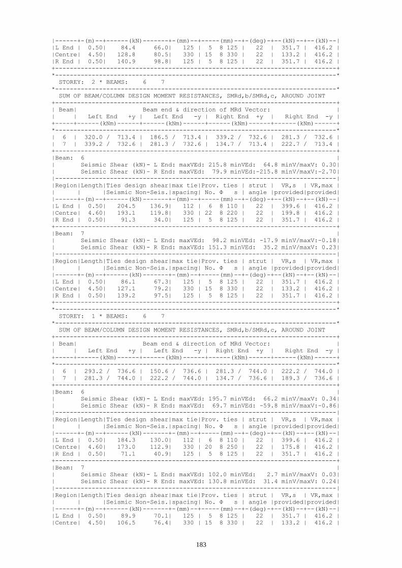
183
|------+-(m)--+------(kN)-------+-(mm)--+-----(mm)--+-(deg)-+--(kN)--+--(kN)--|
|L End | 0.50| 84.4 66.0| 125 | 5 8 125 | 22 | 351.7 | 416.2 |
|Centre| 4.50| 128.8 80.5| 330 | 15 8 330 | 22 | 133.2 | 416.2 |
|R End | 0.50| 140.9 98.8| 125 | 5 8 125 | 22 | 351.7 | 416.2 |
+-----------------------------------------------------------------------------+
*-----------------------------------------------------------------------------*
STOREY: 2 * BEAMS: 6 7
*-----------------------------------------------------------------------------*
SUM OF BEAM/COLUMN DESIGN MOMENT RESISTANCES, SMRd,b/SMRd,c, AROUND JOINT
+-----------------------------------------------------------------------------+
| Beam| Beam end & direction of MRd Vector: |
| | Left End +y | Left End -y | Right End +y | Right End -y |
+-----+------(kNm)------+------(kNm)------+------(kNm)------+------(kNm)------+
*-----------------------------------------------------------------------------*
| 6 | 320.0 / 713.4 | 186.5 / 713.4 | 339.2 / 732.6 | 281.3 / 732.6 |
| 7 | 339.2 / 732.6 | 281.3 / 732.6 | 134.7 / 713.4 | 222.7 / 713.4 |
+-----------------------------------------------------------------------------+
|Beam: 6 |
| Seismic Shear (kN)- L End: maxVEd: 215.8 minVEd: 64.8 minV/maxV: 0.30|
| Seismic Shear (kN)- R End: maxVEd: 79.9 minVEd:-215.8 minV/maxV:-2.70|
|-----------------------------------------------------------------------------|
|Region|Length|Ties design shear|max tie|Prov. ties | strut | VR,s | VR,max |
| | |Seismic Non-Seis.|spacing| No. Φ s | angle |provided|provided|
|------+-(m)--+------(kN)-------+-(mm)--+-----(mm)--+-(deg)-+--(kN)--+--(kN)--|
|L End | 0.50| 204.5 136.9| 112 | 6 8 110 | 22 | 399.6 | 416.2 |
|Centre| 4.60| 193.1 119.8| 330 | 22 8 220 | 22 | 199.8 | 416.2 |
|R End | 0.50| 91.3 34.0| 125 | 5 8 125 | 22 | 351.7 | 416.2 |
+-----------------------------------------------------------------------------+
|Beam: 7 |
| Seismic Shear (kN)- L End: maxVEd: 98.2 minVEd: -17.9 minV/maxV:-0.18|
| Seismic Shear (kN)- R End: maxVEd: 151.3 minVEd: 35.2 minV/maxV: 0.23|
|-----------------------------------------------------------------------------|
|Region|Length|Ties design shear|max tie|Prov. ties | strut | VR,s | VR,max |
| | |Seismic Non-Seis.|spacing| No. Φ s | angle |provided|provided|
|------+-(m)--+------(kN)-------+-(mm)--+-----(mm)--+-(deg)-+--(kN)--+--(kN)--|
|L End | 0.50| 86.1 67.3| 125 | 5 8 125 | 22 | 351.7 | 416.2 |
|Centre| 4.50| 127.1 79.2| 330 | 15 8 330 | 22 | 133.2 | 416.2 |
|R End | 0.50| 139.2 97.5| 125 | 5 8 125 | 22 | 351.7 | 416.2 |
+-----------------------------------------------------------------------------+
*-----------------------------------------------------------------------------*
STOREY: 1 * BEAMS: 6 7
*-----------------------------------------------------------------------------*
SUM OF BEAM/COLUMN DESIGN MOMENT RESISTANCES, SMRd,b/SMRd,c, AROUND JOINT
+-----------------------------------------------------------------------------+
| Beam| Beam end & direction of MRd Vector: |
| | Left End +y | Left End -y | Right End +y | Right End -y |
+-----+------(kNm)------+------(kNm)------+------(kNm)------+------(kNm)------+
*-----------------------------------------------------------------------------*
| 6 | 293.2 / 736.6 | 150.6 / 736.6 | 281.3 / 744.0 | 222.2 / 744.0 |
| 7 | 281.3 / 744.0 | 222.2 / 744.0 | 134.7 / 736.6 | 189.3 / 736.6 |
+-----------------------------------------------------------------------------+
|Beam: 6 |
| Seismic Shear (kN)- L End: maxVEd: 195.7 minVEd: 66.2 minV/maxV: 0.34|
| Seismic Shear (kN)- R End: maxVEd: 69.7 minVEd: -59.8 minV/maxV:-0.86|
|-----------------------------------------------------------------------------|
|Region|Length|Ties design shear|max tie|Prov. ties | strut | VR,s | VR,max |
| | |Seismic Non-Seis.|spacing| No. Φ s | angle |provided|provided|
|------+-(m)--+------(kN)-------+-(mm)--+-----(mm)--+-(deg)-+--(kN)--+--(kN)--|
|L End | 0.50| 184.3 130.0| 112 | 6 8 110 | 22 | 399.6 | 416.2 |
|Centre| 4.60| 173.0 112.9| 330 | 20 8 250 | 22 | 175.8 | 416.2 |
|R End | 0.50| 71.1 40.9| 125 | 5 8 125 | 22 | 351.7 | 416.2 |
+-----------------------------------------------------------------------------+
|Beam: 7 |
| Seismic Shear (kN)- L End: maxVEd: 102.0 minVEd: 2.7 minV/maxV: 0.03|
| Seismic Shear (kN)- R End: maxVEd: 130.8 minVEd: 31.4 minV/maxV: 0.24|
|-----------------------------------------------------------------------------|
|Region|Length|Ties design shear|max tie|Prov. ties | strut | VR,s | VR,max |
| | |Seismic Non-Seis.|spacing| No. Φ s | angle |provided|provided|
|------+-(m)--+------(kN)-------+-(mm)--+-----(mm)--+-(deg)-+--(kN)--+--(kN)--|
|L End | 0.50| 89.9 70.1| 125 | 5 8 125 | 22 | 351.7 | 416.2 |
|Centre| 4.50| 106.5 76.4| 330 | 15 8 330 | 22 | 133.2 | 416.2 |

184
|R End | 0.50| 118.6 94.7| 112 | 6 8 110 | 22 | 399.6 | 416.2 |
+-----------------------------------------------------------------------------+
*-----------------------------------------------------------------------------*
STOREY: 0 * BEAMS: 6 7
*-----------------------------------------------------------------------------*
SUM OF BEAM/COLUMN DESIGN MOMENT RESISTANCES, SMRd,b/SMRd,c, AROUND JOINT
+-----------------------------------------------------------------------------+
| Beam| Beam end & direction of MRd Vector: |
| | Left End +y | Left End -y | Right End +y | Right End -y |
+-----+------(kNm)------+------(kNm)------+------(kNm)------+------(kNm)------+
*-----------------------------------------------------------------------------*
| 6 | 216.4 / 744.5 | 43.5 / 744.5 | 168.2 / 729.7 | 86.6 / 729.7 |
| 7 | 168.2 / 729.7 | 86.6 / 729.7 | 43.5 / 744.5 | 114.4 / 744.5 |
+-----------------------------------------------------------------------------+
|Beam: 6 |
|-----------------------------------------------------------------------------|
|Region|Length|Ties design shear|max tie|Prov. ties | strut | VR,s | VR,max |
| | |Seismic Non-Seis.|spacing| No. Φ s | angle |provided|provided|
|------+-(m)--+------(kN)-------+-(mm)--+-----(mm)--+-(deg)-+--(kN)--+--(kN)--|
|L End | 0.50| 96.4 127.9| 330 | 3 8 330 | 22 | 133.2 | 416.2 |
|Centre| 4.60| 85.1 110.8| 330 | 15 8 330 | 22 | 133.2 | 416.2 |
|R End | 0.50| 40.3 43.0| 330 | 3 8 330 | 22 | 133.2 | 416.2 |
+-----------------------------------------------------------------------------+
|Beam: 7 |
|-----------------------------------------------------------------------------|
|Region|Length|Ties design shear|max tie|Prov. ties | strut | VR,s | VR,max |
| | |Seismic Non-Seis.|spacing| No. Φ s | angle |provided|provided|
|------+-(m)--+------(kN)-------+-(mm)--+-----(mm)--+-(deg)-+--(kN)--+--(kN)--|
|L End | 0.50| 63.7 72.2| 330 | 3 8 330 | 22 | 133.2 | 416.2 |
|Centre| 4.50| 64.4 74.3| 330 | 15 8 330 | 22 | 133.2 | 416.2 |
|R End | 0.50| 76.5 92.6| 330 | 3 8 330 | 22 | 133.2 | 416.2 |
+-----------------------------------------------------------------------------+
*-----------------------------------------------------------------------------*
STOREY: -1 * BEAMS: 6 7
*-----------------------------------------------------------------------------*
SUM OF BEAM/COLUMN DESIGN MOMENT RESISTANCES, SMRd,b/SMRd,c, AROUND JOINT
+-----------------------------------------------------------------------------+
| Beam| Beam end & direction of MRd Vector: |
| | Left End +y | Left End -y | Right End +y | Right End -y |
+-----+------(kNm)------+------(kNm)------+------(kNm)------+------(kNm)------+
*-----------------------------------------------------------------------------*
| 6 | 173.3 / 731.7 | 43.5 / 731.7 | 166.6 / 690.0 | 166.6 / 690.0 |
| 7 | 166.6 / 690.0 | 166.6 / 690.0 | 43.5 / 731.7 | 151.9 / 731.7 |
+-----------------------------------------------------------------------------+
|Beam: 6 |
|-----------------------------------------------------------------------------|
|Region|Length|Ties design shear|max tie|Prov. ties | strut | VR,s | VR,max |
| | |Seismic Non-Seis.|spacing| No. Φ s | angle |provided|provided|
|------+-(m)--+------(kN)-------+-(mm)--+-----(mm)--+-(deg)-+--(kN)--+--(kN)--|
|L End | 0.50| 78.1 116.5| 330 | 3 8 330 | 22 | 133.2 | 416.2 |
|Centre| 4.60| 66.8 99.5| 330 | 15 8 330 | 22 | 133.2 | 416.2 |
|R End | 0.50| 37.1 54.4| 330 | 3 8 330 | 22 | 133.2 | 416.2 |
+-----------------------------------------------------------------------------+
|Beam: 7 |
|-----------------------------------------------------------------------------|
|Region|Length|Ties design shear|max tie|Prov. ties | strut | VR,s | VR,max |
| | |Seismic Non-Seis.|spacing| No. Φ s | angle |provided|provided|
|------+-(m)--+------(kN)-------+-(mm)--+-----(mm)--+-(deg)-+--(kN)--+--(kN)--|
|L End | 0.50| 52.2 75.8| 330 | 3 8 330 | 22 | 133.2 | 416.2 |
|Centre| 4.50| 48.1 70.7| 330 | 15 8 330 | 22 | 133.2 | 416.2 |
|R End | 0.50| 60.3 89.0| 330 | 3 8 330 | 22 | 133.2 | 416.2 |
+-----------------------------------------------------------------------------+
8.3 Frame C
+-----------------------------------------------------------------------------+
SHEAR FORCES - ULS DESIGN OF TRANSVERSE REINFORCEMENT
+-----------------------------------------------------------------------------+
* Concrete: C25 - Long. Reinforcement: S500 - Stirrups: S500 - Cover: 35(mm) *
*-----------------------------------------------------------------------------*

185
STOREY: 6 * BEAMS: 10 11 12 13 14
*-----------------------------------------------------------------------------*
SUM OF BEAM/COLUMN DESIGN MOMENT RESISTANCES, SMRd,b/SMRd,c, AROUND JOINT
+-----------------------------------------------------------------------------+
| Beam| Beam end & direction of MRd Vector: |
| | Left End +y | Left End -y | Right End +y | Right End -y |
+-----+------(kNm)------+------(kNm)------+------(kNm)------+------(kNm)------+
*-----------------------------------------------------------------------------*
| 10 | 100.7 / 80.7 | 87.2 / 80.7 | 197.6 / 319.6 | 197.6 / 319.6 |
| 11 | 197.6 / 319.6 | 197.6 / 319.6 | 197.6 / 314.6 | 197.6 / 314.6 |
| 12 | 197.6 / 314.6 | 197.6 / 314.6 | 197.6 / 314.6 | 197.6 / 314.6 |
| 13 | 197.6 / 314.6 | 197.6 / 314.6 | 87.9 / 319.6 | 109.8 / 319.6 |
| 14 | 87.9 / 319.6 | 109.8 / 319.6 | 87.2 / 80.7 | 100.7 / 80.7 |
+-----------------------------------------------------------------------------+
|Beam: 10 |
| Seismic Shear (kN)- L End: maxVEd: 75.8 minVEd: 10.5 minV/maxV: 0.14|
| Seismic Shear (kN)- R End: maxVEd: 56.2 minVEd: -9.1 minV/maxV:-0.16|
|-----------------------------------------------------------------------------|
|Region|Length|Ties design shear|max tie|Prov. ties | strut | VR,s | VR,max |
| | |Seismic Non-Seis.|spacing| No. Φ s | angle |provided|provided|
|------+-(m)--+------(kN)-------+-(mm)--+-----(mm)--+-(deg)-+--(kN)--+--(kN)--|
|L End | 0.50| 69.8 50.5| 96 | 7 8 95 | 23 | 434.9 | 434.9 |
|Centre| 4.50| 63.7 41.3| 330 | 15 8 330 | 22 | 133.2 | 416.2 |
|R End | 0.50| 50.1 31.9| 96 | 7 8 95 | 23 | 434.9 | 434.9 |
+-----------------------------------------------------------------------------+
|Beam: 11 |
| Seismic Shear (kN)- L End: maxVEd: 62.3 minVEd: -12.2 minV/maxV:-0.20|
| Seismic Shear (kN)- R End: maxVEd: 76.5 minVEd: 1.9 minV/maxV: 0.03|
|-----------------------------------------------------------------------------|
|Region|Length|Ties design shear|max tie|Prov. ties | strut | VR,s | VR,max |
| | |Seismic Non-Seis.|spacing| No. Φ s | angle |provided|provided|
|------+-(m)--+------(kN)-------+-(mm)--+-----(mm)--+-(deg)-+--(kN)--+--(kN)--|
|L End | 0.50| 56.5 34.3| 96 | 7 8 95 | 23 | 434.9 | 434.9 |
|Centre| 4.30| 64.8 36.3| 330 | 15 8 330 | 22 | 133.2 | 416.2 |
|R End | 0.50| 70.7 45.1| 96 | 7 8 95 | 23 | 434.9 | 434.9 |
+-----------------------------------------------------------------------------+
|Beam: 12 |
| Seismic Shear (kN)- L End: maxVEd: 70.3 minVEd: -4.3 minV/maxV:-0.06|
| Seismic Shear (kN)- R End: maxVEd: 68.6 minVEd: -6.0 minV/maxV:-0.09|
|-----------------------------------------------------------------------------|
|Region|Length|Ties design shear|max tie|Prov. ties | strut | VR,s | VR,max |
| | |Seismic Non-Seis.|spacing| No. Φ s | angle |provided|provided|
|------+-(m)--+------(kN)-------+-(mm)--+-----(mm)--+-(deg)-+--(kN)--+--(kN)--|
|L End | 0.50| 64.4 40.3| 96 | 7 8 95 | 23 | 434.9 | 434.9 |
|Centre| 4.30| 58.6 31.4| 330 | 15 8 330 | 22 | 133.2 | 416.2 |
|R End | 0.50| 62.8 39.1| 96 | 7 8 95 | 23 | 434.9 | 434.9 |
+-----------------------------------------------------------------------------+
|Beam: 13 |
| Seismic Shear (kN)- L End: maxVEd: 75.7 minVEd: 1.1 minV/maxV: 0.01|
| Seismic Shear (kN)- R End: maxVEd: 63.2 minVEd: -11.4 minV/maxV:-0.18|
|-----------------------------------------------------------------------------|
|Region|Length|Ties design shear|max tie|Prov. ties | strut | VR,s | VR,max |
| | |Seismic Non-Seis.|spacing| No. Φ s | angle |provided|provided|
|------+-(m)--+------(kN)-------+-(mm)--+-----(mm)--+-(deg)-+--(kN)--+--(kN)--|
|L End | 0.50| 69.9 44.5| 96 | 7 8 95 | 23 | 434.9 | 434.9 |
|Centre| 4.30| 64.0 35.7| 330 | 15 8 330 | 22 | 133.2 | 416.2 |
|R End | 0.50| 57.3 34.9| 96 | 7 8 95 | 23 | 434.9 | 434.9 |
+-----------------------------------------------------------------------------+
|Beam: 14 |
| Seismic Shear (kN)- L End: maxVEd: 36.2 minVEd: 6.9 minV/maxV: 0.19|
| Seismic Shear (kN)- R End: maxVEd: 59.9 minVEd: 30.5 minV/maxV: 0.51|
|-----------------------------------------------------------------------------|
|Region|Length|Ties design shear|max tie|Prov. ties | strut | VR,s | VR,max |
| | |Seismic Non-Seis.|spacing| No. Φ s | angle |provided|provided|
|------+-(m)--+------(kN)-------+-(mm)--+-----(mm)--+-(deg)-+--(kN)--+--(kN)--|
|L End | 0.50| 30.2 32.0| 96 | 7 8 95 | 23 | 434.9 | 434.9 |
|Centre| 4.50| 47.7 41.3| 330 | 15 8 330 | 22 | 133.2 | 416.2 |
|R End | 0.50| 53.8 50.4| 96 | 7 8 95 | 23 | 434.9 | 434.9 |
+-----------------------------------------------------------------------------+
*-----------------------------------------------------------------------------*
STOREY: 5 * BEAMS: 10 11 12 13 14

186
*-----------------------------------------------------------------------------*
SUM OF BEAM/COLUMN DESIGN MOMENT RESISTANCES, SMRd,b/SMRd,c, AROUND JOINT
+-----------------------------------------------------------------------------+
| Beam| Beam end & direction of MRd Vector: |
| | Left End +y | Left End -y | Right End +y | Right End -y |
+-----+------(kNm)------+------(kNm)------+------(kNm)------+------(kNm)------+
*-----------------------------------------------------------------------------*
| 10 | 133.7 / 182.8 | 87.2 / 182.8 | 274.4 / 681.2 | 255.3 / 681.2 |
| 11 | 274.4 / 681.2 | 255.3 / 681.2 | 231.2 / 668.5 | 231.2 / 668.5 |
| 12 | 231.2 / 668.5 | 231.2 / 668.5 | 231.2 / 668.5 | 231.2 / 668.5 |
| 13 | 231.2 / 668.5 | 231.2 / 668.5 | 145.5 / 681.2 | 128.9 / 681.2 |
| 14 | 145.5 / 681.2 | 128.9 / 681.2 | 87.2 / 182.8 | 133.7 / 182.8 |
+-----------------------------------------------------------------------------+
|Beam: 10 |
| Seismic Shear (kN)- L End: maxVEd: 104.3 minVEd: 17.7 minV/maxV: 0.17|
| Seismic Shear (kN)- R End: maxVEd: 49.0 minVEd: -37.6 minV/maxV:-0.77|
|-----------------------------------------------------------------------------|
|Region|Length|Ties design shear|max tie|Prov. ties | strut | VR,s | VR,max |
| | |Seismic Non-Seis.|spacing| No. Φ s | angle |provided|provided|
|------+-(m)--+------(kN)-------+-(mm)--+-----(mm)--+-(deg)-+--(kN)--+--(kN)--|
|L End | 0.50| 98.2 60.1| 112 | 6 8 110 | 22 | 399.6 | 416.2 |
|Centre| 4.50| 92.1 51.0| 330 | 15 8 330 | 22 | 133.2 | 416.2 |
|R End | 0.50| 43.6 22.3| 96 | 7 8 95 | 22 | 434.9 | 434.9 |
+-----------------------------------------------------------------------------+
|Beam: 11 |
| Seismic Shear (kN)- L End: maxVEd: 65.8 minVEd: -29.6 minV/maxV:-0.45|
| Seismic Shear (kN)- R End: maxVEd: 93.9 minVEd: -1.5 minV/maxV:-0.02|
|-----------------------------------------------------------------------------|
|Region|Length|Ties design shear|max tie|Prov. ties | strut | VR,s | VR,max |
| | |Seismic Non-Seis.|spacing| No. Φ s | angle |provided|provided|
|------+-(m)--+------(kN)-------+-(mm)--+-----(mm)--+-(deg)-+--(kN)--+--(kN)--|
|L End | 0.50| 59.9 34.2| 96 | 7 8 95 | 23 | 434.9 | 434.9 |
|Centre| 4.30| 82.2 36.4| 330 | 15 8 330 | 22 | 133.2 | 416.2 |
|R End | 0.50| 88.1 45.2| 112 | 6 8 110 | 23 | 399.6 | 416.2 |
+-----------------------------------------------------------------------------+
|Beam: 12 |
| Seismic Shear (kN)- L End: maxVEd: 76.6 minVEd: -10.6 minV/maxV:-0.14|
| Seismic Shear (kN)- R End: maxVEd: 74.9 minVEd: -12.3 minV/maxV:-0.16|
|-----------------------------------------------------------------------------|
|Region|Length|Ties design shear|max tie|Prov. ties | strut | VR,s | VR,max |
| | |Seismic Non-Seis.|spacing| No. Φ s | angle |provided|provided|
|------+-(m)--+------(kN)-------+-(mm)--+-----(mm)--+-(deg)-+--(kN)--+--(kN)--|
|L End | 0.50| 70.8 40.3| 112 | 6 8 110 | 22 | 399.6 | 416.2 |
|Centre| 4.30| 64.9 31.5| 330 | 15 8 330 | 22 | 133.2 | 416.2 |
|R End | 0.50| 69.1 39.1| 112 | 6 8 110 | 22 | 399.6 | 416.2 |
+-----------------------------------------------------------------------------+
|Beam: 13 |
| Seismic Shear (kN)- L End: maxVEd: 93.2 minVEd: -2.2 minV/maxV:-0.02|
| Seismic Shear (kN)- R End: maxVEd: 66.5 minVEd: -28.9 minV/maxV:-0.44|
|-----------------------------------------------------------------------------|
|Region|Length|Ties design shear|max tie|Prov. ties | strut | VR,s | VR,max |
| | |Seismic Non-Seis.|spacing| No. Φ s | angle |provided|provided|
|------+-(m)--+------(kN)-------+-(mm)--+-----(mm)--+-(deg)-+--(kN)--+--(kN)--|
|L End | 0.50| 87.4 44.8| 112 | 6 8 110 | 22 | 399.6 | 416.2 |
|Centre| 4.30| 81.5 35.9| 330 | 15 8 330 | 22 | 133.2 | 416.2 |
|R End | 0.50| 60.6 34.7| 96 | 7 8 95 | 22 | 434.9 | 434.9 |
+-----------------------------------------------------------------------------+
|Beam: 14 |
| Seismic Shear (kN)- L End: maxVEd: 29.1 minVEd: -11.1 minV/maxV:-0.38|
| Seismic Shear (kN)- R End: maxVEd: 77.8 minVEd: 37.6 minV/maxV: 0.48|
|-----------------------------------------------------------------------------|
|Region|Length|Ties design shear|max tie|Prov. ties | strut | VR,s | VR,max |
| | |Seismic Non-Seis.|spacing| No. Φ s | angle |provided|provided|
|------+-(m)--+------(kN)-------+-(mm)--+-----(mm)--+-(deg)-+--(kN)--+--(kN)--|
|L End | 0.50| 23.0 22.3| 96 | 7 8 95 | 23 | 434.9 | 434.9 |
|Centre| 4.50| 65.7 50.9| 330 | 15 8 330 | 22 | 133.2 | 416.2 |
|R End | 0.50| 71.7 60.1| 112 | 6 8 110 | 23 | 399.6 | 416.2 |
+-----------------------------------------------------------------------------+
*-----------------------------------------------------------------------------*
STOREY: 4 * BEAMS: 10 11 12 13 14
*-----------------------------------------------------------------------------*

187
SUM OF BEAM/COLUMN DESIGN MOMENT RESISTANCES, SMRd,b/SMRd,c, AROUND JOINT
+-----------------------------------------------------------------------------+
| Beam| Beam end & direction of MRd Vector: |
| | Left End +y | Left End -y | Right End +y | Right End -y |
+-----+------(kNm)------+------(kNm)------+------(kNm)------+------(kNm)------+
*-----------------------------------------------------------------------------*
| 10 | 133.7 / 218.4 | 87.2 / 218.4 | 293.0 / 751.7 | 255.3 / 751.7 |
| 11 | 293.0 / 751.7 | 255.3 / 751.7 | 245.4 / 734.3 | 273.9 / 734.3 |
| 12 | 245.4 / 734.3 | 273.9 / 734.3 | 281.9 / 734.3 | 235.3 / 734.3 |
| 13 | 281.9 / 734.3 | 235.3 / 734.3 | 145.5 / 751.7 | 147.5 / 751.7 |
| 14 | 145.5 / 751.7 | 147.5 / 751.7 | 87.2 / 218.4 | 133.7 / 218.4 |
+-----------------------------------------------------------------------------+
|Beam: 10 |
| Seismic Shear (kN)- L End: maxVEd: 103.1 minVEd: 16.6 minV/maxV: 0.16|
| Seismic Shear (kN)- R End: maxVEd: 50.1 minVEd: -36.4 minV/maxV:-0.73|
|-----------------------------------------------------------------------------|
|Region|Length|Ties design shear|max tie|Prov. ties | strut | VR,s | VR,max |
| | |Seismic Non-Seis.|spacing| No. Φ s | angle |provided|provided|
|------+-(m)--+------(kN)-------+-(mm)--+-----(mm)--+-(deg)-+--(kN)--+--(kN)--|
|L End | 0.50| 97.1 58.7| 112 | 6 8 110 | 22 | 399.6 | 416.2 |
|Centre| 4.50| 91.0 49.6| 330 | 15 8 330 | 22 | 133.2 | 416.2 |
|R End | 0.50| 44.1 23.7| 96 | 7 8 95 | 22 | 434.9 | 434.9 |
+-----------------------------------------------------------------------------+
|Beam: 11 |
| Seismic Shear (kN)- L End: maxVEd: 69.7 minVEd: -31.9 minV/maxV:-0.46|
| Seismic Shear (kN)- R End: maxVEd: 96.2 minVEd: -5.4 minV/maxV:-0.06|
|-----------------------------------------------------------------------------|
|Region|Length|Ties design shear|max tie|Prov. ties | strut | VR,s | VR,max |
| | |Seismic Non-Seis.|spacing| No. Φ s | angle |provided|provided|
|------+-(m)--+------(kN)-------+-(mm)--+-----(mm)--+-(deg)-+--(kN)--+--(kN)--|
|L End | 0.50| 63.9 34.5| 96 | 7 8 95 | 23 | 434.9 | 434.9 |
|Centre| 4.30| 84.5 36.1| 330 | 15 8 330 | 22 | 133.2 | 416.2 |
|R End | 0.50| 90.3 44.9| 112 | 6 8 110 | 23 | 399.6 | 416.2 |
+-----------------------------------------------------------------------------+
|Beam: 12 |
| Seismic Shear (kN)- L End: maxVEd: 84.6 minVEd: -16.9 minV/maxV:-0.20|
| Seismic Shear (kN)- R End: maxVEd: 81.2 minVEd: -20.3 minV/maxV:-0.25|
|-----------------------------------------------------------------------------|
|Region|Length|Ties design shear|max tie|Prov. ties | strut | VR,s | VR,max |
| | |Seismic Non-Seis.|spacing| No. Φ s | angle |provided|provided|
|------+-(m)--+------(kN)-------+-(mm)--+-----(mm)--+-(deg)-+--(kN)--+--(kN)--|
|L End | 0.50| 78.7 40.2| 112 | 6 8 110 | 22 | 399.6 | 416.2 |
|Centre| 4.30| 72.9 31.4| 330 | 15 8 330 | 22 | 133.2 | 416.2 |
|R End | 0.50| 75.3 39.2| 96 | 7 8 95 | 22 | 434.9 | 434.9 |
+-----------------------------------------------------------------------------+
|Beam: 13 |
| Seismic Shear (kN)- L End: maxVEd: 97.1 minVEd: -6.0 minV/maxV:-0.06|
| Seismic Shear (kN)- R End: maxVEd: 70.3 minVEd: -32.8 minV/maxV:-0.47|
|-----------------------------------------------------------------------------|
|Region|Length|Ties design shear|max tie|Prov. ties | strut | VR,s | VR,max |
| | |Seismic Non-Seis.|spacing| No. Φ s | angle |provided|provided|
|------+-(m)--+------(kN)-------+-(mm)--+-----(mm)--+-(deg)-+--(kN)--+--(kN)--|
|L End | 0.50| 91.2 44.5| 96 | 7 8 95 | 23 | 434.9 | 434.9 |
|Centre| 4.30| 85.4 35.7| 330 | 15 8 330 | 22 | 133.2 | 416.2 |
|R End | 0.50| 64.5 34.9| 96 | 7 8 95 | 23 | 434.9 | 434.9 |
+-----------------------------------------------------------------------------+
|Beam: 14 |
| Seismic Shear (kN)- L End: maxVEd: 30.2 minVEd: -10.0 minV/maxV:-0.33|
| Seismic Shear (kN)- R End: maxVEd: 76.7 minVEd: 36.5 minV/maxV: 0.48|
|-----------------------------------------------------------------------------|
|Region|Length|Ties design shear|max tie|Prov. ties | strut | VR,s | VR,max |
| | |Seismic Non-Seis.|spacing| No. Φ s | angle |provided|provided|
|------+-(m)--+------(kN)-------+-(mm)--+-----(mm)--+-(deg)-+--(kN)--+--(kN)--|
|L End | 0.50| 24.1 23.7| 96 | 7 8 95 | 23 | 434.9 | 434.9 |
|Centre| 4.50| 64.6 49.6| 330 | 15 8 330 | 22 | 133.2 | 416.2 |
|R End | 0.50| 70.6 58.7| 112 | 6 8 110 | 23 | 399.6 | 416.2 |
+-----------------------------------------------------------------------------+
*-----------------------------------------------------------------------------*
STOREY: 3 * BEAMS: 10 11 12 13 14
*-----------------------------------------------------------------------------*
SUM OF BEAM/COLUMN DESIGN MOMENT RESISTANCES, SMRd,b/SMRd,c, AROUND JOINT

188
+-----------------------------------------------------------------------------+
| Beam| Beam end & direction of MRd Vector: |
| | Left End +y | Left End -y | Right End +y | Right End -y |
+-----+------(kNm)------+------(kNm)------+------(kNm)------+------(kNm)------+
*-----------------------------------------------------------------------------*
| 10 | 133.7 / 246.7 | 87.2 / 246.7 | 293.0 / 809.0 | 255.3 / 809.0 |
| 11 | 293.0 / 809.0 | 255.3 / 809.0 | 245.4 / 789.2 | 273.9 / 789.2 |
| 12 | 245.4 / 789.2 | 273.9 / 789.2 | 273.9 / 789.2 | 245.4 / 789.2 |
| 13 | 273.9 / 789.2 | 245.4 / 789.2 | 145.5 / 809.0 | 147.5 / 809.0 |
| 14 | 145.5 / 809.0 | 147.5 / 809.0 | 87.2 / 246.7 | 133.7 / 246.7 |
+-----------------------------------------------------------------------------+
|Beam: 10 |
| Seismic Shear (kN)- L End: maxVEd: 103.0 minVEd: 16.4 minV/maxV: 0.16|
| Seismic Shear (kN)- R End: maxVEd: 50.3 minVEd: -36.2 minV/maxV:-0.72|
|-----------------------------------------------------------------------------|
|Region|Length|Ties design shear|max tie|Prov. ties | strut | VR,s | VR,max |
| | |Seismic Non-Seis.|spacing| No. Φ s | angle |provided|provided|
|------+-(m)--+------(kN)-------+-(mm)--+-----(mm)--+-(deg)-+--(kN)--+--(kN)--|
|L End | 0.50| 96.9 58.4| 112 | 6 8 110 | 22 | 399.6 | 416.2 |
|Centre| 4.50| 90.8 49.2| 330 | 15 8 330 | 22 | 133.2 | 416.2 |
|R End | 0.50| 44.3 24.0| 96 | 7 8 95 | 22 | 434.9 | 434.9 |
+-----------------------------------------------------------------------------+
|Beam: 11 |
| Seismic Shear (kN)- L End: maxVEd: 70.0 minVEd: -31.6 minV/maxV:-0.45|
| Seismic Shear (kN)- R End: maxVEd: 95.9 minVEd: -5.7 minV/maxV:-0.06|
|-----------------------------------------------------------------------------|
|Region|Length|Ties design shear|max tie|Prov. ties | strut | VR,s | VR,max |
| | |Seismic Non-Seis.|spacing| No. Φ s | angle |provided|provided|
|------+-(m)--+------(kN)-------+-(mm)--+-----(mm)--+-(deg)-+--(kN)--+--(kN)--|
|L End | 0.50| 64.2 34.7| 96 | 7 8 95 | 23 | 434.9 | 434.9 |
|Centre| 4.30| 84.2 35.9| 330 | 15 8 330 | 22 | 133.2 | 416.2 |
|R End | 0.50| 90.0 44.7| 112 | 6 8 110 | 23 | 399.6 | 416.2 |
+-----------------------------------------------------------------------------+
|Beam: 12 |
| Seismic Shear (kN)- L End: maxVEd: 84.5 minVEd: -18.9 minV/maxV:-0.22|
| Seismic Shear (kN)- R End: maxVEd: 83.2 minVEd: -20.2 minV/maxV:-0.24|
|-----------------------------------------------------------------------------|
|Region|Length|Ties design shear|max tie|Prov. ties | strut | VR,s | VR,max |
| | |Seismic Non-Seis.|spacing| No. Φ s | angle |provided|provided|
|------+-(m)--+------(kN)-------+-(mm)--+-----(mm)--+-(deg)-+--(kN)--+--(kN)--|
|L End | 0.50| 78.6 40.1| 112 | 6 8 110 | 22 | 399.6 | 416.2 |
|Centre| 4.30| 72.8 31.3| 330 | 15 8 330 | 22 | 133.2 | 416.2 |
|R End | 0.50| 77.3 39.3| 112 | 6 8 110 | 22 | 399.6 | 416.2 |
+-----------------------------------------------------------------------------+
|Beam: 13 |
| Seismic Shear (kN)- L End: maxVEd: 95.3 minVEd: -6.3 minV/maxV:-0.07|
| Seismic Shear (kN)- R End: maxVEd: 70.5 minVEd: -31.0 minV/maxV:-0.44|
|-----------------------------------------------------------------------------|
|Region|Length|Ties design shear|max tie|Prov. ties | strut | VR,s | VR,max |
| | |Seismic Non-Seis.|spacing| No. Φ s | angle |provided|provided|
|------+-(m)--+------(kN)-------+-(mm)--+-----(mm)--+-(deg)-+--(kN)--+--(kN)--|
|L End | 0.50| 89.5 44.3| 112 | 6 8 110 | 22 | 399.6 | 416.2 |
|Centre| 4.30| 83.6 35.5| 330 | 15 8 330 | 22 | 133.2 | 416.2 |
|R End | 0.50| 64.7 35.1| 96 | 7 8 95 | 22 | 434.9 | 434.9 |
+-----------------------------------------------------------------------------+
|Beam: 14 |
| Seismic Shear (kN)- L End: maxVEd: 30.4 minVEd: -9.8 minV/maxV:-0.32|
| Seismic Shear (kN)- R End: maxVEd: 76.5 minVEd: 36.3 minV/maxV: 0.48|
|-----------------------------------------------------------------------------|
|Region|Length|Ties design shear|max tie|Prov. ties | strut | VR,s | VR,max |
| | |Seismic Non-Seis.|spacing| No. Φ s | angle |provided|provided|
|------+-(m)--+------(kN)-------+-(mm)--+-----(mm)--+-(deg)-+--(kN)--+--(kN)--|
|L End | 0.50| 24.3 24.0| 96 | 7 8 95 | 23 | 434.9 | 434.9 |
|Centre| 4.50| 64.4 49.2| 330 | 15 8 330 | 22 | 133.2 | 416.2 |
|R End | 0.50| 70.4 58.3| 112 | 6 8 110 | 23 | 399.6 | 416.2 |
+-----------------------------------------------------------------------------+
*-----------------------------------------------------------------------------*
STOREY: 2 * BEAMS: 10 11 12 13 14
*-----------------------------------------------------------------------------*
SUM OF BEAM/COLUMN DESIGN MOMENT RESISTANCES, SMRd,b/SMRd,c, AROUND JOINT
+-----------------------------------------------------------------------------+

189
| Beam| Beam end & direction of MRd Vector: |
| | Left End +y | Left End -y | Right End +y | Right End -y |
+-----+------(kNm)------+------(kNm)------+------(kNm)------+------(kNm)------+
*-----------------------------------------------------------------------------*
| 10 | 133.7 / 267.7 | 87.2 / 267.7 | 293.0 / 852.9 | 255.3 / 852.9 |
| 11 | 293.0 / 852.9 | 255.3 / 852.9 | 245.4 / 833.3 | 273.9 / 833.3 |
| 12 | 245.4 / 833.3 | 273.9 / 833.3 | 273.9 / 833.3 | 245.4 / 833.3 |
| 13 | 273.9 / 833.3 | 245.4 / 833.3 | 145.5 / 852.9 | 147.5 / 852.9 |
| 14 | 145.5 / 852.9 | 147.5 / 852.9 | 87.2 / 267.7 | 133.7 / 267.7 |
+-----------------------------------------------------------------------------+
|Beam: 10 |
| Seismic Shear (kN)- L End: maxVEd: 102.9 minVEd: 16.3 minV/maxV: 0.16|
| Seismic Shear (kN)- R End: maxVEd: 50.4 minVEd: -36.2 minV/maxV:-0.72|
|-----------------------------------------------------------------------------|
|Region|Length|Ties design shear|max tie|Prov. ties | strut | VR,s | VR,max |
| | |Seismic Non-Seis.|spacing| No. Φ s | angle |provided|provided|
|------+-(m)--+------(kN)-------+-(mm)--+-----(mm)--+-(deg)-+--(kN)--+--(kN)--|
|L End | 0.50| 96.8 58.0| 112 | 6 8 110 | 22 | 399.6 | 416.2 |
|Centre| 4.50| 90.8 48.9| 330 | 15 8 330 | 22 | 133.2 | 416.2 |
|R End | 0.50| 44.3 24.4| 96 | 7 8 95 | 22 | 434.9 | 434.9 |
+-----------------------------------------------------------------------------+
|Beam: 11 |
| Seismic Shear (kN)- L End: maxVEd: 70.3 minVEd: -31.3 minV/maxV:-0.44|
| Seismic Shear (kN)- R End: maxVEd: 95.5 minVEd: -6.0 minV/maxV:-0.06|
|-----------------------------------------------------------------------------|
|Region|Length|Ties design shear|max tie|Prov. ties | strut | VR,s | VR,max |
| | |Seismic Non-Seis.|spacing| No. Φ s | angle |provided|provided|
|------+-(m)--+------(kN)-------+-(mm)--+-----(mm)--+-(deg)-+--(kN)--+--(kN)--|
|L End | 0.50| 64.5 35.0| 96 | 7 8 95 | 23 | 434.9 | 434.9 |
|Centre| 4.30| 83.9 35.6| 330 | 15 8 330 | 22 | 133.2 | 416.2 |
|R End | 0.50| 89.7 44.4| 112 | 6 8 110 | 23 | 399.6 | 416.2 |
+-----------------------------------------------------------------------------+
|Beam: 12 |
| Seismic Shear (kN)- L End: maxVEd: 84.4 minVEd: -19.0 minV/maxV:-0.22|
| Seismic Shear (kN)- R End: maxVEd: 83.2 minVEd: -20.1 minV/maxV:-0.24|
|-----------------------------------------------------------------------------|
|Region|Length|Ties design shear|max tie|Prov. ties | strut | VR,s | VR,max |
| | |Seismic Non-Seis.|spacing| No. Φ s | angle |provided|provided|
|------+-(m)--+------(kN)-------+-(mm)--+-----(mm)--+-(deg)-+--(kN)--+--(kN)--|
|L End | 0.50| 78.6 40.1| 112 | 6 8 110 | 22 | 399.6 | 416.2 |
|Centre| 4.30| 72.7 31.3| 330 | 15 8 330 | 22 | 133.2 | 416.2 |
|R End | 0.50| 77.4 39.3| 112 | 6 8 110 | 22 | 399.6 | 416.2 |
+-----------------------------------------------------------------------------+
|Beam: 13 |
| Seismic Shear (kN)- L End: maxVEd: 95.0 minVEd: -6.5 minV/maxV:-0.07|
| Seismic Shear (kN)- R End: maxVEd: 70.8 minVEd: -30.8 minV/maxV:-0.43|
|-----------------------------------------------------------------------------|
|Region|Length|Ties design shear|max tie|Prov. ties | strut | VR,s | VR,max |
| | |Seismic Non-Seis.|spacing| No. Φ s | angle |provided|provided|
|------+-(m)--+------(kN)-------+-(mm)--+-----(mm)--+-(deg)-+--(kN)--+--(kN)--|
|L End | 0.50| 89.2 44.1| 112 | 6 8 110 | 22 | 399.6 | 416.2 |
|Centre| 4.30| 83.4 35.3| 330 | 15 8 330 | 22 | 133.2 | 416.2 |
|R End | 0.50| 65.0 35.3| 96 | 7 8 95 | 22 | 434.9 | 434.9 |
+-----------------------------------------------------------------------------+
|Beam: 14 |
| Seismic Shear (kN)- L End: maxVEd: 30.4 minVEd: -9.7 minV/maxV:-0.32|
| Seismic Shear (kN)- R End: maxVEd: 76.4 minVEd: 36.3 minV/maxV: 0.47|
|-----------------------------------------------------------------------------|
|Region|Length|Ties design shear|max tie|Prov. ties | strut | VR,s | VR,max |
| | |Seismic Non-Seis.|spacing| No. Φ s | angle |provided|provided|
|------+-(m)--+------(kN)-------+-(mm)--+-----(mm)--+-(deg)-+--(kN)--+--(kN)--|
|L End | 0.50| 24.4 24.4| 96 | 7 8 95 | 23 | 434.9 | 434.9 |
|Centre| 4.50| 64.3 48.9| 330 | 15 8 330 | 22 | 133.2 | 416.2 |
|R End | 0.50| 70.4 58.0| 112 | 6 8 110 | 23 | 399.6 | 416.2 |
+-----------------------------------------------------------------------------+
*-----------------------------------------------------------------------------*
STOREY: 1 * BEAMS: 10 11 12 13 14
*-----------------------------------------------------------------------------*
SUM OF BEAM/COLUMN DESIGN MOMENT RESISTANCES, SMRd,b/SMRd,c, AROUND JOINT
+-----------------------------------------------------------------------------+
| Beam| Beam end & direction of MRd Vector: |

190
| | Left End +y | Left End -y | Right End +y | Right End -y |
+-----+------(kNm)------+------(kNm)------+------(kNm)------+------(kNm)------+
*-----------------------------------------------------------------------------*
| 10 | 120.1 / 282.1 | 87.2 / 282.1 | 245.2 / 883.2 | 197.6 / 883.2 |
| 11 | 245.2 / 883.2 | 197.6 / 883.2 | 221.4 / 866.2 | 221.4 / 866.2 |
| 12 | 221.4 / 866.2 | 221.4 / 866.2 | 221.4 / 866.2 | 221.4 / 866.2 |
| 13 | 221.4 / 866.2 | 221.4 / 866.2 | 87.9 / 883.2 | 128.9 / 883.2 |
| 14 | 87.9 / 883.2 | 128.9 / 883.2 | 87.2 / 282.1 | 120.1 / 282.1 |
+-----------------------------------------------------------------------------+
|Beam: 10 |
| Seismic Shear (kN)- L End: maxVEd: 92.1 minVEd: 13.3 minV/maxV: 0.14|
| Seismic Shear (kN)- R End: maxVEd: 53.4 minVEd: -25.4 minV/maxV:-0.48|
|-----------------------------------------------------------------------------|
|Region|Length|Ties design shear|max tie|Prov. ties | strut | VR,s | VR,max |
| | |Seismic Non-Seis.|spacing| No. Φ s | angle |provided|provided|
|------+-(m)--+------(kN)-------+-(mm)--+-----(mm)--+-(deg)-+--(kN)--+--(kN)--|
|L End | 0.50| 86.1 54.5| 96 | 7 8 95 | 23 | 434.9 | 434.9 |
|Centre| 4.50| 80.0 45.3| 330 | 15 8 330 | 22 | 133.2 | 416.2 |
|R End | 0.50| 47.3 27.9| 96 | 7 8 95 | 23 | 434.9 | 434.9 |
+-----------------------------------------------------------------------------+
|Beam: 11 |
| Seismic Shear (kN)- L End: maxVEd: 67.8 minVEd: -14.8 minV/maxV:-0.22|
| Seismic Shear (kN)- R End: maxVEd: 79.1 minVEd: -3.5 minV/maxV:-0.04|
|-----------------------------------------------------------------------------|
|Region|Length|Ties design shear|max tie|Prov. ties | strut | VR,s | VR,max |
| | |Seismic Non-Seis.|spacing| No. Φ s | angle |provided|provided|
|------+-(m)--+------(kN)-------+-(mm)--+-----(mm)--+-(deg)-+--(kN)--+--(kN)--|
|L End | 0.50| 62.0 35.7| 96 | 7 8 95 | 23 | 434.9 | 434.9 |
|Centre| 4.30| 67.4 34.8| 330 | 15 8 330 | 22 | 133.2 | 416.2 |
|R End | 0.50| 73.3 43.7| 112 | 6 8 110 | 23 | 399.6 | 416.2 |
+-----------------------------------------------------------------------------+
|Beam: 12 |
| Seismic Shear (kN)- L End: maxVEd: 74.4 minVEd: -9.2 minV/maxV:-0.12|
| Seismic Shear (kN)- R End: maxVEd: 73.4 minVEd: -10.1 minV/maxV:-0.14|
|-----------------------------------------------------------------------------|
|Region|Length|Ties design shear|max tie|Prov. ties | strut | VR,s | VR,max |
| | |Seismic Non-Seis.|spacing| No. Φ s | angle |provided|provided|
|------+-(m)--+------(kN)-------+-(mm)--+-----(mm)--+-(deg)-+--(kN)--+--(kN)--|
|L End | 0.50| 68.6 40.0| 112 | 6 8 110 | 22 | 399.6 | 416.2 |
|Centre| 4.30| 62.7 31.2| 330 | 15 8 330 | 22 | 133.2 | 416.2 |
|R End | 0.50| 67.6 39.4| 112 | 6 8 110 | 22 | 399.6 | 416.2 |
+-----------------------------------------------------------------------------+
|Beam: 13 |
| Seismic Shear (kN)- L End: maxVEd: 78.7 minVEd: -4.0 minV/maxV:-0.05|
| Seismic Shear (kN)- R End: maxVEd: 68.3 minVEd: -14.4 minV/maxV:-0.21|
|-----------------------------------------------------------------------------|
|Region|Length|Ties design shear|max tie|Prov. ties | strut | VR,s | VR,max |
| | |Seismic Non-Seis.|spacing| No. Φ s | angle |provided|provided|
|------+-(m)--+------(kN)-------+-(mm)--+-----(mm)--+-(deg)-+--(kN)--+--(kN)--|
|L End | 0.50| 72.8 43.4| 112 | 6 8 110 | 22 | 399.6 | 416.2 |
|Centre| 4.30| 67.0 34.5| 330 | 15 8 330 | 22 | 133.2 | 416.2 |
|R End | 0.50| 62.4 36.0| 96 | 7 8 95 | 22 | 434.9 | 434.9 |
+-----------------------------------------------------------------------------+
|Beam: 14 |
| Seismic Shear (kN)- L End: maxVEd: 33.4 minVEd: -4.3 minV/maxV:-0.13|
| Seismic Shear (kN)- R End: maxVEd: 71.0 minVEd: 33.3 minV/maxV: 0.47|
|-----------------------------------------------------------------------------|
|Region|Length|Ties design shear|max tie|Prov. ties | strut | VR,s | VR,max |
| | |Seismic Non-Seis.|spacing| No. Φ s | angle |provided|provided|
|------+-(m)--+------(kN)-------+-(mm)--+-----(mm)--+-(deg)-+--(kN)--+--(kN)--|
|L End | 0.50| 27.3 27.9| 96 | 7 8 95 | 23 | 434.9 | 434.9 |
|Centre| 4.50| 58.9 45.4| 330 | 15 8 330 | 22 | 133.2 | 416.2 |
|R End | 0.50| 64.9 54.5| 96 | 7 8 95 | 23 | 434.9 | 434.9 |
+-----------------------------------------------------------------------------+
*-----------------------------------------------------------------------------*
STOREY: 0 * BEAMS: 10 11 12 13 14
*-----------------------------------------------------------------------------*
SUM OF BEAM/COLUMN DESIGN MOMENT RESISTANCES, SMRd,b/SMRd,c, AROUND JOINT
+-----------------------------------------------------------------------------+
| Beam| Beam end & direction of MRd Vector: |
| | Left End +y | Left End -y | Right End +y | Right End -y |
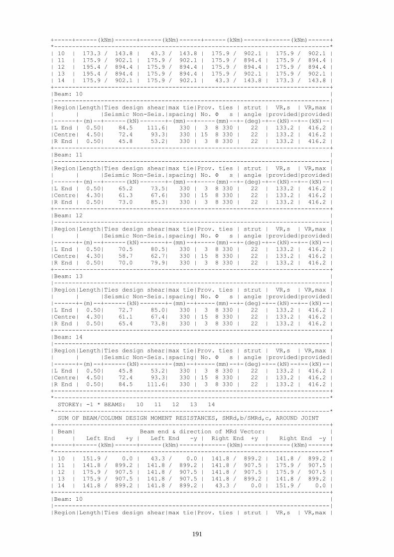
191
+-----+------(kNm)------+------(kNm)------+------(kNm)------+------(kNm)------+
*-----------------------------------------------------------------------------*
| 10 | 173.3 / 143.8 | 43.3 / 143.8 | 175.9 / 902.1 | 175.9 / 902.1 |
| 11 | 175.9 / 902.1 | 175.9 / 902.1 | 175.9 / 894.4 | 175.9 / 894.4 |
| 12 | 195.4 / 894.4 | 175.9 / 894.4 | 175.9 / 894.4 | 175.9 / 894.4 |
| 13 | 195.4 / 894.4 | 175.9 / 894.4 | 175.9 / 902.1 | 175.9 / 902.1 |
| 14 | 175.9 / 902.1 | 175.9 / 902.1 | 43.3 / 143.8 | 173.3 / 143.8 |
+-----------------------------------------------------------------------------+
|Beam: 10 |
|-----------------------------------------------------------------------------|
|Region|Length|Ties design shear|max tie|Prov. ties | strut | VR,s | VR,max |
| | |Seismic Non-Seis.|spacing| No. Φ s | angle |provided|provided|
|------+-(m)--+------(kN)-------+-(mm)--+-----(mm)--+-(deg)-+--(kN)--+--(kN)--|
|L End | 0.50| 84.5 111.6| 330 | 3 8 330 | 22 | 133.2 | 416.2 |
|Centre| 4.50| 72.4 93.3| 330 | 15 8 330 | 22 | 133.2 | 416.2 |
|R End | 0.50| 45.8 53.2| 330 | 3 8 330 | 22 | 133.2 | 416.2 |
+-----------------------------------------------------------------------------+
|Beam: 11 |
|-----------------------------------------------------------------------------|
|Region|Length|Ties design shear|max tie|Prov. ties | strut | VR,s | VR,max |
| | |Seismic Non-Seis.|spacing| No. Φ s | angle |provided|provided|
|------+-(m)--+------(kN)-------+-(mm)--+-----(mm)--+-(deg)-+--(kN)--+--(kN)--|
|L End | 0.50| 65.2 73.5| 330 | 3 8 330 | 22 | 133.2 | 416.2 |
|Centre| 4.30| 61.3 67.6| 330 | 15 8 330 | 22 | 133.2 | 416.2 |
|R End | 0.50| 73.0 85.3| 330 | 3 8 330 | 22 | 133.2 | 416.2 |
+-----------------------------------------------------------------------------+
|Beam: 12 |
|-----------------------------------------------------------------------------|
|Region|Length|Ties design shear|max tie|Prov. ties | strut | VR,s | VR,max |
| | |Seismic Non-Seis.|spacing| No. Φ s | angle |provided|provided|
|------+-(m)--+------(kN)-------+-(mm)--+-----(mm)--+-(deg)-+--(kN)--+--(kN)--|
|L End | 0.50| 70.5 80.5| 330 | 3 8 330 | 22 | 133.2 | 416.2 |
|Centre| 4.30| 58.7 62.7| 330 | 15 8 330 | 22 | 133.2 | 416.2 |
|R End | 0.50| 70.0 79.9| 330 | 3 8 330 | 22 | 133.2 | 416.2 |
+-----------------------------------------------------------------------------+
|Beam: 13 |
|-----------------------------------------------------------------------------|
|Region|Length|Ties design shear|max tie|Prov. ties | strut | VR,s | VR,max |
| | |Seismic Non-Seis.|spacing| No. Φ s | angle |provided|provided|
|------+-(m)--+------(kN)-------+-(mm)--+-----(mm)--+-(deg)-+--(kN)--+--(kN)--|
|L End | 0.50| 72.7 85.0| 330 | 3 8 330 | 22 | 133.2 | 416.2 |
|Centre| 4.30| 61.1 67.4| 330 | 15 8 330 | 22 | 133.2 | 416.2 |
|R End | 0.50| 65.4 73.8| 330 | 3 8 330 | 22 | 133.2 | 416.2 |
+-----------------------------------------------------------------------------+
|Beam: 14 |
|-----------------------------------------------------------------------------|
|Region|Length|Ties design shear|max tie|Prov. ties | strut | VR,s | VR,max |
| | |Seismic Non-Seis.|spacing| No. Φ s | angle |provided|provided|
|------+-(m)--+------(kN)-------+-(mm)--+-----(mm)--+-(deg)-+--(kN)--+--(kN)--|
|L End | 0.50| 45.8 53.2| 330 | 3 8 330 | 22 | 133.2 | 416.2 |
|Centre| 4.50| 72.4 93.3| 330 | 15 8 330 | 22 | 133.2 | 416.2 |
|R End | 0.50| 84.5 111.6| 330 | 3 8 330 | 22 | 133.2 | 416.2 |
+-----------------------------------------------------------------------------+
*-----------------------------------------------------------------------------*
STOREY: -1 * BEAMS: 10 11 12 13 14
*-----------------------------------------------------------------------------*
SUM OF BEAM/COLUMN DESIGN MOMENT RESISTANCES, SMRd,b/SMRd,c, AROUND JOINT
+-----------------------------------------------------------------------------+
| Beam| Beam end & direction of MRd Vector: |
| | Left End +y | Left End -y | Right End +y | Right End -y |
+-----+------(kNm)------+------(kNm)------+------(kNm)------+------(kNm)------+
*-----------------------------------------------------------------------------*
| 10 | 151.9 / 0.0 | 43.3 / 0.0 | 141.8 / 899.2 | 141.8 / 899.2 |
| 11 | 141.8 / 899.2 | 141.8 / 899.2 | 141.8 / 907.5 | 175.9 / 907.5 |
| 12 | 175.9 / 907.5 | 141.8 / 907.5 | 141.8 / 907.5 | 175.9 / 907.5 |
| 13 | 175.9 / 907.5 | 141.8 / 907.5 | 141.8 / 899.2 | 141.8 / 899.2 |
| 14 | 141.8 / 899.2 | 141.8 / 899.2 | 43.3 / 0.0 | 151.9 / 0.0 |
+-----------------------------------------------------------------------------+
|Beam: 10 |
|-----------------------------------------------------------------------------|
|Region|Length|Ties design shear|max tie|Prov. ties | strut | VR,s | VR,max |

192
| | |Seismic Non-Seis.|spacing| No. Φ s | angle |provided|provided|
|------+-(m)--+------(kN)-------+-(mm)--+-----(mm)--+-(deg)-+--(kN)--+--(kN)--|
|L End | 0.50| 71.0 104.6| 330 | 3 8 330 | 22 | 133.2 | 416.2 |
|Centre| 4.50| 58.9 86.3| 330 | 15 8 330 | 22 | 133.2 | 416.2 |
|R End | 0.50| 41.7 60.2| 330 | 3 8 330 | 22 | 133.2 | 416.2 |
+-----------------------------------------------------------------------------+
|Beam: 11 |
|-----------------------------------------------------------------------------|
|Region|Length|Ties design shear|max tie|Prov. ties | strut | VR,s | VR,max |
| | |Seismic Non-Seis.|spacing| No. Φ s | angle |provided|provided|
|------+-(m)--+------(kN)-------+-(mm)--+-----(mm)--+-(deg)-+--(kN)--+--(kN)--|
|L End | 0.50| 50.9 75.0| 330 | 3 8 330 | 22 | 133.2 | 416.2 |
|Centre| 4.30| 45.0 66.2| 330 | 15 8 330 | 22 | 133.2 | 416.2 |
|R End | 0.50| 56.7 83.8| 330 | 3 8 330 | 22 | 133.2 | 416.2 |
+-----------------------------------------------------------------------------+
|Beam: 12 |
|-----------------------------------------------------------------------------|
|Region|Length|Ties design shear|max tie|Prov. ties | strut | VR,s | VR,max |
| | |Seismic Non-Seis.|spacing| No. Φ s | angle |provided|provided|
|------+-(m)--+------(kN)-------+-(mm)--+-----(mm)--+-(deg)-+--(kN)--+--(kN)--|
|L End | 0.50| 54.9 80.4| 330 | 3 8 330 | 22 | 133.2 | 416.2 |
|Centre| 4.30| 43.1 62.6| 330 | 15 8 330 | 22 | 133.2 | 416.2 |
|R End | 0.50| 54.6 79.9| 330 | 3 8 330 | 22 | 133.2 | 416.2 |
+-----------------------------------------------------------------------------+
|Beam: 13 |
|-----------------------------------------------------------------------------|
|Region|Length|Ties design shear|max tie|Prov. ties | strut | VR,s | VR,max |
| | |Seismic Non-Seis.|spacing| No. Φ s | angle |provided|provided|
|------+-(m)--+------(kN)-------+-(mm)--+-----(mm)--+-(deg)-+--(kN)--+--(kN)--|
|L End | 0.50| 56.5 83.6| 330 | 3 8 330 | 22 | 133.2 | 416.2 |
|Centre| 4.30| 44.8 65.9| 330 | 15 8 330 | 22 | 133.2 | 416.2 |
|R End | 0.50| 51.1 75.3| 330 | 3 8 330 | 22 | 133.2 | 416.2 |
+-----------------------------------------------------------------------------+
|Beam: 14 |
|-----------------------------------------------------------------------------|
|Region|Length|Ties design shear|max tie|Prov. ties | strut | VR,s | VR,max |
| | |Seismic Non-Seis.|spacing| No. Φ s | angle |provided|provided|
|------+-(m)--+------(kN)-------+-(mm)--+-----(mm)--+-(deg)-+--(kN)--+--(kN)--|
|L End | 0.50| 41.7 60.2| 330 | 3 8 330 | 22 | 133.2 | 416.2 |
|Centre| 4.50| 58.9 86.3| 330 | 15 8 330 | 22 | 133.2 | 416.2 |
|R End | 0.50| 71.0 104.6| 330 | 3 8 330 | 22 | 133.2 | 416.2 |
+-----------------------------------------------------------------------------+
8.4 Frame 1
+-----------------------------------------------------------------------------+
SHEAR FORCES - ULS DESIGN OF TRANSVERSE REINFORCEMENT
+-----------------------------------------------------------------------------+
* Concrete: C25 - Long. Reinforcement: S500 - Stirrups: S500 - Cover: 35(mm) *
*-----------------------------------------------------------------------------*
STOREY: 6 * BEAMS: 22 21
*-----------------------------------------------------------------------------*
SUM OF BEAM/COLUMN DESIGN MOMENT RESISTANCES, SMRd,b/SMRd,c, AROUND JOINT
+-----------------------------------------------------------------------------+
| Beam| Beam end & direction of MRd Vector: |
| | Left End +y | Left End -y | Right End +y | Right End -y |
+-----+------(kNm)------+------(kNm)------+------(kNm)------+------(kNm)------+
*-----------------------------------------------------------------------------*
| 22 | 158.3 / 193.1 | 188.1 / 193.1 | 427.5 / 234.6 | 472.6 / 234.6 |
| 21 | 427.5 / 234.6 | 472.6 / 234.6 | 188.1 / 197.9 | 167.7 / 197.9 |
+-----------------------------------------------------------------------------+
|Beam: 22 |
| Seismic Shear (kN)- L End: maxVEd: 73.3 minVEd: -52.5 minV/maxV:-0.72|
| Seismic Shear (kN)- R End: maxVEd: 117.6 minVEd: -8.1 minV/maxV:-0.07|
|-----------------------------------------------------------------------------|
|Region|Length|Ties design shear|max tie|Prov. ties | strut | VR,s | VR,max |
| | |Seismic Non-Seis.|spacing| No. Φ s | angle |provided|provided|
|------+-(m)--+------(kN)-------+-(mm)--+-----(mm)--+-(deg)-+--(kN)--+--(kN)--|
|L End | 0.50| 66.8 27.7| 125 | 5 8 125 | 22 | 351.7 | 416.2 |
|Centre| 3.70| 104.6 41.2| 330 | 13 8 330 | 22 | 133.2 | 416.2 |
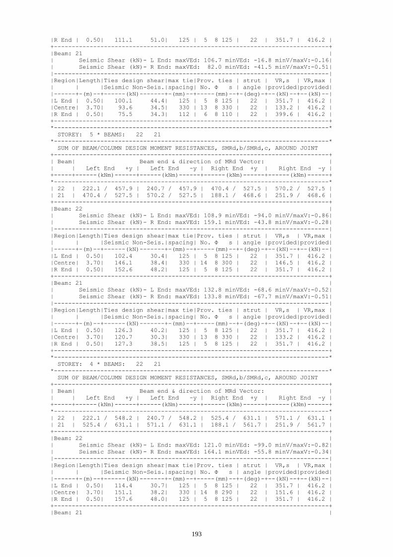
193
|R End | 0.50| 111.1 51.0| 125 | 5 8 125 | 22 | 351.7 | 416.2 |
+-----------------------------------------------------------------------------+
|Beam: 21 |
| Seismic Shear (kN)- L End: maxVEd: 106.7 minVEd: -16.8 minV/maxV:-0.16|
| Seismic Shear (kN)- R End: maxVEd: 82.0 minVEd: -41.5 minV/maxV:-0.51|
|-----------------------------------------------------------------------------|
|Region|Length|Ties design shear|max tie|Prov. ties | strut | VR,s | VR,max |
| | |Seismic Non-Seis.|spacing| No. Φ s | angle |provided|provided|
|------+-(m)--+------(kN)-------+-(mm)--+-----(mm)--+-(deg)-+--(kN)--+--(kN)--|
|L End | 0.50| 100.1 44.4| 125 | 5 8 125 | 22 | 351.7 | 416.2 |
|Centre| 3.70| 93.6 34.5| 330 | 13 8 330 | 22 | 133.2 | 416.2 |
|R End | 0.50| 75.5 34.3| 112 | 6 8 110 | 22 | 399.6 | 416.2 |
+-----------------------------------------------------------------------------+
*-----------------------------------------------------------------------------*
STOREY: 5 * BEAMS: 22 21
*-----------------------------------------------------------------------------*
SUM OF BEAM/COLUMN DESIGN MOMENT RESISTANCES, SMRd,b/SMRd,c, AROUND JOINT
+-----------------------------------------------------------------------------+
| Beam| Beam end & direction of MRd Vector: |
| | Left End +y | Left End -y | Right End +y | Right End -y |
+-----+------(kNm)------+------(kNm)------+------(kNm)------+------(kNm)------+
*-----------------------------------------------------------------------------*
| 22 | 222.1 / 457.9 | 240.7 / 457.9 | 470.4 / 527.5 | 570.2 / 527.5 |
| 21 | 470.4 / 527.5 | 570.2 / 527.5 | 188.1 / 468.6 | 251.9 / 468.6 |
+-----------------------------------------------------------------------------+
|Beam: 22 |
| Seismic Shear (kN)- L End: maxVEd: 108.9 minVEd: -94.0 minV/maxV:-0.86|
| Seismic Shear (kN)- R End: maxVEd: 159.1 minVEd: -43.8 minV/maxV:-0.28|
|-----------------------------------------------------------------------------|
|Region|Length|Ties design shear|max tie|Prov. ties | strut | VR,s | VR,max |
| | |Seismic Non-Seis.|spacing| No. Φ s | angle |provided|provided|
|------+-(m)--+------(kN)-------+-(mm)--+-----(mm)--+-(deg)-+--(kN)--+--(kN)--|
|L End | 0.50| 102.4 30.4| 125 | 5 8 125 | 22 | 351.7 | 416.2 |
|Centre| 3.70| 146.1 38.4| 330 | 14 8 300 | 22 | 146.5 | 416.2 |
|R End | 0.50| 152.6 48.2| 125 | 5 8 125 | 22 | 351.7 | 416.2 |
+-----------------------------------------------------------------------------+
|Beam: 21 |
| Seismic Shear (kN)- L End: maxVEd: 132.8 minVEd: -68.6 minV/maxV:-0.52|
| Seismic Shear (kN)- R End: maxVEd: 133.8 minVEd: -67.7 minV/maxV:-0.51|
|-----------------------------------------------------------------------------|
|Region|Length|Ties design shear|max tie|Prov. ties | strut | VR,s | VR,max |
| | |Seismic Non-Seis.|spacing| No. Φ s | angle |provided|provided|
|------+-(m)--+------(kN)-------+-(mm)--+-----(mm)--+-(deg)-+--(kN)--+--(kN)--|
|L End | 0.50| 126.3 40.2| 125 | 5 8 125 | 22 | 351.7 | 416.2 |
|Centre| 3.70| 120.7 30.3| 330 | 13 8 330 | 22 | 133.2 | 416.2 |
|R End | 0.50| 127.3 38.5| 125 | 5 8 125 | 22 | 351.7 | 416.2 |
+-----------------------------------------------------------------------------+
*-----------------------------------------------------------------------------*
STOREY: 4 * BEAMS: 22 21
*-----------------------------------------------------------------------------*
SUM OF BEAM/COLUMN DESIGN MOMENT RESISTANCES, SMRd,b/SMRd,c, AROUND JOINT
+-----------------------------------------------------------------------------+
| Beam| Beam end & direction of MRd Vector: |
| | Left End +y | Left End -y | Right End +y | Right End -y |
+-----+------(kNm)------+------(kNm)------+------(kNm)------+------(kNm)------+
*-----------------------------------------------------------------------------*
| 22 | 222.1 / 548.2 | 240.7 / 548.2 | 525.4 / 631.1 | 571.1 / 631.1 |
| 21 | 525.4 / 631.1 | 571.1 / 631.1 | 188.1 / 561.7 | 251.9 / 561.7 |
+-----------------------------------------------------------------------------+
|Beam: 22 |
| Seismic Shear (kN)- L End: maxVEd: 121.0 minVEd: -99.0 minV/maxV:-0.82|
| Seismic Shear (kN)- R End: maxVEd: 164.1 minVEd: -55.8 minV/maxV:-0.34|
|-----------------------------------------------------------------------------|
|Region|Length|Ties design shear|max tie|Prov. ties | strut | VR,s | VR,max |
| | |Seismic Non-Seis.|spacing| No. Φ s | angle |provided|provided|
|------+-(m)--+------(kN)-------+-(mm)--+-----(mm)--+-(deg)-+--(kN)--+--(kN)--|
|L End | 0.50| 114.4 30.7| 125 | 5 8 125 | 22 | 351.7 | 416.2 |
|Centre| 3.70| 151.1 38.2| 330 | 14 8 290 | 22 | 151.6 | 416.2 |
|R End | 0.50| 157.6 48.0| 125 | 5 8 125 | 22 | 351.7 | 416.2 |
+-----------------------------------------------------------------------------+
|Beam: 21 |

194
| Seismic Shear (kN)- L End: maxVEd: 133.5 minVEd: -71.9 minV/maxV:-0.54|
| Seismic Shear (kN)- R End: maxVEd: 137.0 minVEd: -68.4 minV/maxV:-0.50|
|-----------------------------------------------------------------------------|
|Region|Length|Ties design shear|max tie|Prov. ties | strut | VR,s | VR,max |
| | |Seismic Non-Seis.|spacing| No. Φ s | angle |provided|provided|
|------+-(m)--+------(kN)-------+-(mm)--+-----(mm)--+-(deg)-+--(kN)--+--(kN)--|
|L End | 0.50| 127.0 40.7| 125 | 5 8 125 | 22 | 351.7 | 416.2 |
|Centre| 3.70| 124.0 30.8| 330 | 13 8 330 | 22 | 133.2 | 416.2 |
|R End | 0.50| 130.5 38.0| 125 | 5 8 125 | 22 | 351.7 | 416.2 |
+-----------------------------------------------------------------------------+
*-----------------------------------------------------------------------------*
STOREY: 3 * BEAMS: 22 21
*-----------------------------------------------------------------------------*
SUM OF BEAM/COLUMN DESIGN MOMENT RESISTANCES, SMRd,b/SMRd,c, AROUND JOINT
+-----------------------------------------------------------------------------+
| Beam| Beam end & direction of MRd Vector: |
| | Left End +y | Left End -y | Right End +y | Right End -y |
+-----+------(kNm)------+------(kNm)------+------(kNm)------+------(kNm)------+
*-----------------------------------------------------------------------------*
| 22 | 222.1 / 591.4 | 240.7 / 591.4 | 470.4 / 700.8 | 527.6 / 700.8 |
| 21 | 470.4 / 700.8 | 527.6 / 700.8 | 188.1 / 606.9 | 251.9 / 606.9 |
+-----------------------------------------------------------------------------+
|Beam: 22 |
| Seismic Shear (kN)- L End: maxVEd: 110.8 minVEd: -88.2 minV/maxV:-0.80|
| Seismic Shear (kN)- R End: maxVEd: 153.4 minVEd: -45.6 minV/maxV:-0.30|
|-----------------------------------------------------------------------------|
|Region|Length|Ties design shear|max tie|Prov. ties | strut | VR,s | VR,max |
| | |Seismic Non-Seis.|spacing| No. Φ s | angle |provided|provided|
|------+-(m)--+------(kN)-------+-(mm)--+-----(mm)--+-(deg)-+--(kN)--+--(kN)--|
|L End | 0.50| 104.3 31.8| 125 | 5 8 125 | 22 | 351.7 | 416.2 |
|Centre| 3.70| 140.3 37.0| 330 | 13 8 310 | 22 | 141.8 | 416.2 |
|R End | 0.50| 146.9 46.9| 125 | 5 8 125 | 22 | 351.7 | 416.2 |
+-----------------------------------------------------------------------------+
|Beam: 21 |
| Seismic Shear (kN)- L End: maxVEd: 133.0 minVEd: -72.4 minV/maxV:-0.54|
| Seismic Shear (kN)- R End: maxVEd: 137.5 minVEd: -67.9 minV/maxV:-0.49|
|-----------------------------------------------------------------------------|
|Region|Length|Ties design shear|max tie|Prov. ties | strut | VR,s | VR,max |
| | |Seismic Non-Seis.|spacing| No. Φ s | angle |provided|provided|
|------+-(m)--+------(kN)-------+-(mm)--+-----(mm)--+-(deg)-+--(kN)--+--(kN)--|
|L End | 0.50| 126.5 40.3| 125 | 5 8 125 | 22 | 351.7 | 416.2 |
|Centre| 3.70| 124.5 30.5| 330 | 13 8 330 | 22 | 133.2 | 416.2 |
|R End | 0.50| 131.0 38.4| 125 | 5 8 125 | 22 | 351.7 | 416.2 |
+-----------------------------------------------------------------------------+
*-----------------------------------------------------------------------------*
STOREY: 2 * BEAMS: 22 21
*-----------------------------------------------------------------------------*
SUM OF BEAM/COLUMN DESIGN MOMENT RESISTANCES, SMRd,b/SMRd,c, AROUND JOINT
+-----------------------------------------------------------------------------+
| Beam| Beam end & direction of MRd Vector: |
| | Left End +y | Left End -y | Right End +y | Right End -y |
+-----+------(kNm)------+------(kNm)------+------(kNm)------+------(kNm)------+
*-----------------------------------------------------------------------------*
| 22 | 200.9 / 624.4 | 188.1 / 624.4 | 434.9 / 732.6 | 470.4 / 732.6 |
| 21 | 434.9 / 732.6 | 470.4 / 732.6 | 188.1 / 639.2 | 219.3 / 639.2 |
+-----------------------------------------------------------------------------+
|Beam: 22 |
| Seismic Shear (kN)- L End: maxVEd: 108.6 minVEd: -74.3 minV/maxV:-0.68|
| Seismic Shear (kN)- R End: maxVEd: 139.4 minVEd: -43.5 minV/maxV:-0.31|
|-----------------------------------------------------------------------------|
|Region|Length|Ties design shear|max tie|Prov. ties | strut | VR,s | VR,max |
| | |Seismic Non-Seis.|spacing| No. Φ s | angle |provided|provided|
|------+-(m)--+------(kN)-------+-(mm)--+-----(mm)--+-(deg)-+--(kN)--+--(kN)--|
|L End | 0.50| 102.1 33.6| 96 | 7 8 95 | 23 | 434.9 | 434.9 |
|Centre| 3.70| 126.4 35.3| 330 | 13 8 330 | 22 | 133.2 | 416.2 |
|R End | 0.50| 132.9 45.1| 125 | 5 8 125 | 23 | 351.7 | 416.2 |
+-----------------------------------------------------------------------------+
|Beam: 21 |
| Seismic Shear (kN)- L End: maxVEd: 124.8 minVEd: -54.4 minV/maxV:-0.44|
| Seismic Shear (kN)- R End: maxVEd: 119.5 minVEd: -59.7 minV/maxV:-0.50|
|-----------------------------------------------------------------------------|

195
|Region|Length|Ties design shear|max tie|Prov. ties | strut | VR,s | VR,max |
| | |Seismic Non-Seis.|spacing| No. Φ s | angle |provided|provided|
|------+-(m)--+------(kN)-------+-(mm)--+-----(mm)--+-(deg)-+--(kN)--+--(kN)--|
|L End | 0.50| 118.3 39.8| 125 | 5 8 125 | 22 | 351.7 | 416.2 |
|Centre| 3.70| 111.8 30.0| 330 | 13 8 330 | 22 | 133.2 | 416.2 |
|R End | 0.50| 113.0 38.9| 125 | 5 8 125 | 22 | 351.7 | 416.2 |
+-----------------------------------------------------------------------------+
*-----------------------------------------------------------------------------*
STOREY: 1 * BEAMS: 22 21
*-----------------------------------------------------------------------------*
SUM OF BEAM/COLUMN DESIGN MOMENT RESISTANCES, SMRd,b/SMRd,c, AROUND JOINT
+-----------------------------------------------------------------------------+
| Beam| Beam end & direction of MRd Vector: |
| | Left End +y | Left End -y | Right End +y | Right End -y |
+-----+------(kNm)------+------(kNm)------+------(kNm)------+------(kNm)------+
*-----------------------------------------------------------------------------*
| 22 | 158.3 / 646.8 | 133.3 / 646.8 | 324.0 / 744.0 | 324.0 / 744.0 |
| 21 | 324.0 / 744.0 | 324.0 / 744.0 | 133.3 / 658.6 | 167.7 / 658.6 |
+-----------------------------------------------------------------------------+
|Beam: 22 |
| Seismic Shear (kN)- L End: maxVEd: 88.6 minVEd: -42.4 minV/maxV:-0.48|
| Seismic Shear (kN)- R End: maxVEd: 107.5 minVEd: -23.5 minV/maxV:-0.22|
|-----------------------------------------------------------------------------|
|Region|Length|Ties design shear|max tie|Prov. ties | strut | VR,s | VR,max |
| | |Seismic Non-Seis.|spacing| No. Φ s | angle |provided|provided|
|------+-(m)--+------(kN)-------+-(mm)--+-----(mm)--+-(deg)-+--(kN)--+--(kN)--|
|L End | 0.50| 82.1 34.4| 125 | 5 8 125 | 22 | 351.7 | 416.2 |
|Centre| 3.70| 94.5 34.4| 330 | 13 8 330 | 22 | 133.2 | 416.2 |
|R End | 0.50| 101.0 44.3| 125 | 5 8 125 | 22 | 351.7 | 416.2 |
+-----------------------------------------------------------------------------+
|Beam: 21 |
| Seismic Shear (kN)- L End: maxVEd: 102.9 minVEd: -30.1 minV/maxV:-0.29|
| Seismic Shear (kN)- R End: maxVEd: 95.2 minVEd: -37.7 minV/maxV:-0.40|
|-----------------------------------------------------------------------------|
|Region|Length|Ties design shear|max tie|Prov. ties | strut | VR,s | VR,max |
| | |Seismic Non-Seis.|spacing| No. Φ s | angle |provided|provided|
|------+-(m)--+------(kN)-------+-(mm)--+-----(mm)--+-(deg)-+--(kN)--+--(kN)--|
|L End | 0.50| 96.4 40.8| 125 | 5 8 125 | 22 | 351.7 | 416.2 |
|Centre| 3.70| 89.9 30.9| 330 | 13 8 330 | 22 | 133.2 | 416.2 |
|R End | 0.50| 88.7 37.9| 112 | 6 8 110 | 22 | 399.6 | 416.2 |
+-----------------------------------------------------------------------------+
8.5 Frame 2
+-----------------------------------------------------------------------------+
SHEAR FORCES - ULS DESIGN OF TRANSVERSE REINFORCEMENT
+-----------------------------------------------------------------------------+
* Concrete: C25 - Long. Reinforcement: S500 - Stirrups: S500 - Cover: 35(mm) *
*-----------------------------------------------------------------------------*
STOREY: 6 * BEAMS: 28 27
*-----------------------------------------------------------------------------*
SUM OF BEAM/COLUMN DESIGN MOMENT RESISTANCES, SMRd,b/SMRd,c, AROUND JOINT
+-----------------------------------------------------------------------------+
| Beam| Beam end & direction of MRd Vector: |
| | Left End +y | Left End -y | Right End +y | Right End -y |
+-----+------(kNm)------+------(kNm)------+------(kNm)------+------(kNm)------+
*-----------------------------------------------------------------------------*
| 28 | 163.5 / 109.1 | 88.0 / 109.1 | 314.3 / 234.6 | 314.3 / 234.6 |
| 27 | 314.3 / 234.6 | 314.3 / 234.6 | 88.0 / 96.9 | 145.3 / 96.9 |
+-----------------------------------------------------------------------------+
|Beam: 28 |
| Seismic Shear (kN)- L End: maxVEd: 112.4 minVEd: 47.0 minV/maxV: 0.42|
| Seismic Shear (kN)- R End: maxVEd: 136.0 minVEd: 70.6 minV/maxV: 0.52|
|-----------------------------------------------------------------------------|
|Region|Length|Ties design shear|max tie|Prov. ties | strut | VR,s | VR,max |
| | |Seismic Non-Seis.|spacing| No. Φ s | angle |provided|provided|
|------+-(m)--+------(kN)-------+-(mm)--+-----(mm)--+-(deg)-+--(kN)--+--(kN)--|
|L End | 0.50| 99.4 114.1| 96 | 7 8 95 | 23 | 434.9 | 434.9 |
|Centre| 5.60| 109.8 102.9| 330 | 18 8 330 | 22 | 133.2 | 416.2 |
|R End | 0.50| 122.9 122.7| 96 | 7 8 95 | 23 | 434.9 | 434.9 |

196
+-----------------------------------------------------------------------------+
|Beam: 27 |
| Seismic Shear (kN)- L End: maxVEd: 143.4 minVEd: 79.8 minV/maxV: 0.56|
| Seismic Shear (kN)- R End: maxVEd: 103.2 minVEd: 39.6 minV/maxV: 0.38|
|-----------------------------------------------------------------------------|
|Region|Length|Ties design shear|max tie|Prov. ties | strut | VR,s | VR,max |
| | |Seismic Non-Seis.|spacing| No. Φ s | angle |provided|provided|
|------+-(m)--+------(kN)-------+-(mm)--+-----(mm)--+-(deg)-+--(kN)--+--(kN)--|
|L End | 0.50| 130.3 128.2| 96 | 7 8 95 | 23 | 434.9 | 434.9 |
|Centre| 5.60| 117.2 108.5| 330 | 18 8 330 | 22 | 133.2 | 416.2 |
|R End | 0.50| 90.1 108.5| 96 | 7 8 95 | 23 | 434.9 | 434.9 |
+-----------------------------------------------------------------------------+
*-----------------------------------------------------------------------------*
STOREY: 5 * BEAMS: 28 27
*-----------------------------------------------------------------------------*
SUM OF BEAM/COLUMN DESIGN MOMENT RESISTANCES, SMRd,b/SMRd,c, AROUND JOINT
+-----------------------------------------------------------------------------+
| Beam| Beam end & direction of MRd Vector: |
| | Left End +y | Left End -y | Right End +y | Right End -y |
+-----+------(kNm)------+------(kNm)------+------(kNm)------+------(kNm)------+
*-----------------------------------------------------------------------------*
| 28 | 213.0 / 220.7 | 116.6 / 220.7 | 321.6 / 527.5 | 311.0 / 527.5 |
| 27 | 321.6 / 527.5 | 311.0 / 527.5 | 116.6 / 215.8 | 182.6 / 215.8 |
+-----------------------------------------------------------------------------+
|Beam: 28 |
| Seismic Shear (kN)- L End: maxVEd: 151.6 minVEd: 58.9 minV/maxV: 0.39|
| Seismic Shear (kN)- R End: maxVEd: 124.1 minVEd: 31.4 minV/maxV: 0.25|
|-----------------------------------------------------------------------------|
|Region|Length|Ties design shear|max tie|Prov. ties | strut | VR,s | VR,max |
| | |Seismic Non-Seis.|spacing| No. Φ s | angle |provided|provided|
|------+-(m)--+------(kN)-------+-(mm)--+-----(mm)--+-(deg)-+--(kN)--+--(kN)--|
|L End | 0.50| 138.5 129.2| 112 | 6 8 110 | 22 | 399.6 | 416.2 |
|Centre| 5.60| 125.5 109.5| 330 | 18 8 330 | 22 | 133.2 | 416.2 |
|R End | 0.50| 111.0 107.6| 112 | 6 8 110 | 22 | 399.6 | 416.2 |
+-----------------------------------------------------------------------------+
|Beam: 27 |
| Seismic Shear (kN)- L End: maxVEd: 142.1 minVEd: 43.6 minV/maxV: 0.31|
| Seismic Shear (kN)- R End: maxVEd: 139.4 minVEd: 40.9 minV/maxV: 0.29|
|-----------------------------------------------------------------------------|
|Region|Length|Ties design shear|max tie|Prov. ties | strut | VR,s | VR,max |
| | |Seismic Non-Seis.|spacing| No. Φ s | angle |provided|provided|
|------+-(m)--+------(kN)-------+-(mm)--+-----(mm)--+-(deg)-+--(kN)--+--(kN)--|
|L End | 0.50| 129.0 116.6| 112 | 6 8 110 | 22 | 399.6 | 416.2 |
|Centre| 5.60| 115.9 100.4| 330 | 18 8 330 | 22 | 133.2 | 416.2 |
|R End | 0.50| 126.3 120.2| 112 | 6 8 110 | 22 | 399.6 | 416.2 |
+-----------------------------------------------------------------------------+
*-----------------------------------------------------------------------------*
STOREY: 4 * BEAMS: 28 27
*-----------------------------------------------------------------------------*
SUM OF BEAM/COLUMN DESIGN MOMENT RESISTANCES, SMRd,b/SMRd,c, AROUND JOINT
+-----------------------------------------------------------------------------+
| Beam| Beam end & direction of MRd Vector: |
| | Left End +y | Left End -y | Right End +y | Right End -y |
+-----+------(kNm)------+------(kNm)------+------(kNm)------+------(kNm)------+
*-----------------------------------------------------------------------------*
| 28 | 198.3 / 260.4 | 116.6 / 260.4 | 321.6 / 631.1 | 311.0 / 631.1 |
| 27 | 321.6 / 631.1 | 311.0 / 631.1 | 116.6 / 253.1 | 181.1 / 253.1 |
+-----------------------------------------------------------------------------+
|Beam: 28 |
| Seismic Shear (kN)- L End: maxVEd: 146.7 minVEd: 56.2 minV/maxV: 0.38|
| Seismic Shear (kN)- R End: maxVEd: 126.8 minVEd: 36.3 minV/maxV: 0.29|
|-----------------------------------------------------------------------------|
|Region|Length|Ties design shear|max tie|Prov. ties | strut | VR,s | VR,max |
| | |Seismic Non-Seis.|spacing| No. Φ s | angle |provided|provided|
|------+-(m)--+------(kN)-------+-(mm)--+-----(mm)--+-(deg)-+--(kN)--+--(kN)--|
|L End | 0.50| 133.6 127.2| 96 | 7 8 95 | 23 | 434.9 | 434.9 |
|Centre| 5.60| 120.5 107.4| 330 | 18 8 330 | 22 | 133.2 | 416.2 |
|R End | 0.50| 113.7 109.6| 112 | 6 8 110 | 23 | 399.6 | 416.2 |
+-----------------------------------------------------------------------------+
|Beam: 27 |
| Seismic Shear (kN)- L End: maxVEd: 144.7 minVEd: 46.4 minV/maxV: 0.32|
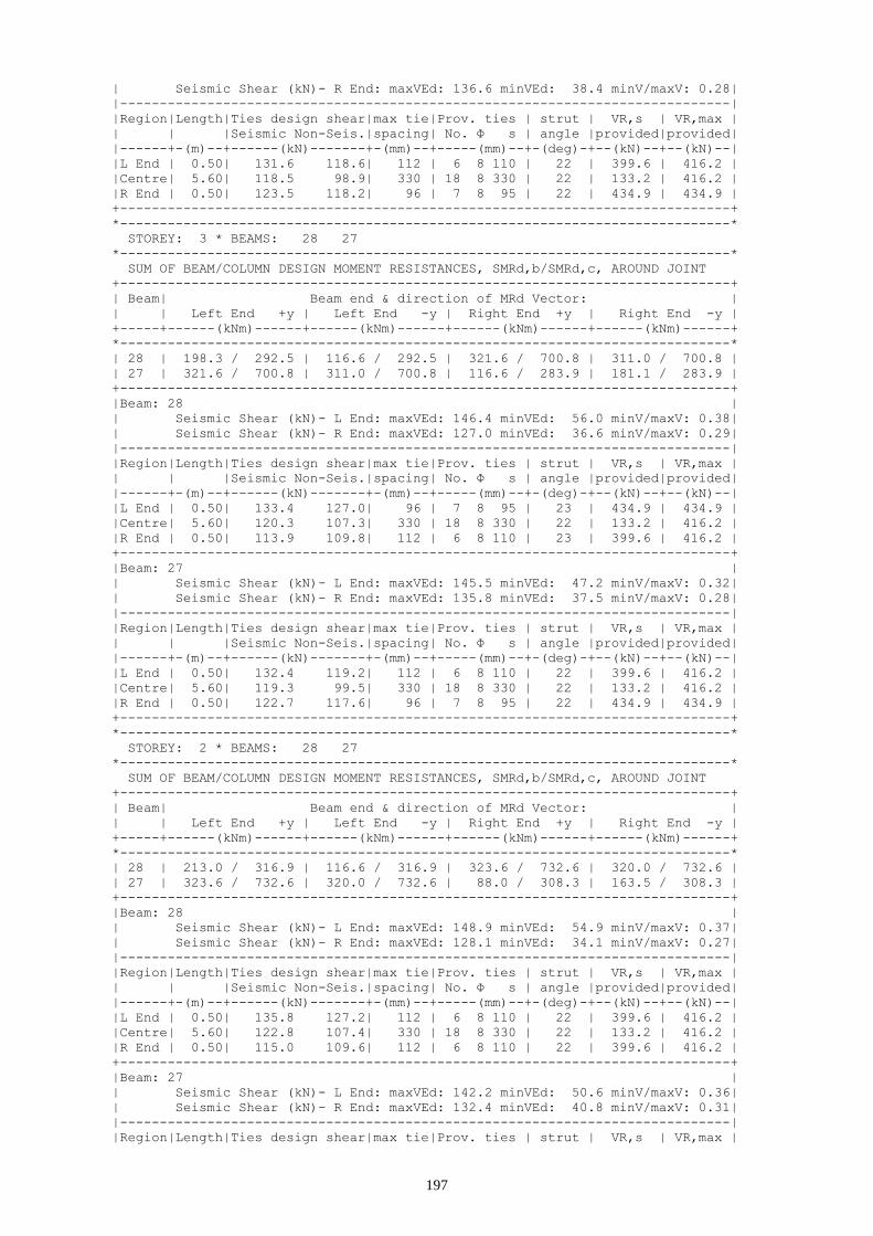
197
| Seismic Shear (kN)- R End: maxVEd: 136.6 minVEd: 38.4 minV/maxV: 0.28|
|-----------------------------------------------------------------------------|
|Region|Length|Ties design shear|max tie|Prov. ties | strut | VR,s | VR,max |
| | |Seismic Non-Seis.|spacing| No. Φ s | angle |provided|provided|
|------+-(m)--+------(kN)-------+-(mm)--+-----(mm)--+-(deg)-+--(kN)--+--(kN)--|
|L End | 0.50| 131.6 118.6| 112 | 6 8 110 | 22 | 399.6 | 416.2 |
|Centre| 5.60| 118.5 98.9| 330 | 18 8 330 | 22 | 133.2 | 416.2 |
|R End | 0.50| 123.5 118.2| 96 | 7 8 95 | 22 | 434.9 | 434.9 |
+-----------------------------------------------------------------------------+
*-----------------------------------------------------------------------------*
STOREY: 3 * BEAMS: 28 27
*-----------------------------------------------------------------------------*
SUM OF BEAM/COLUMN DESIGN MOMENT RESISTANCES, SMRd,b/SMRd,c, AROUND JOINT
+-----------------------------------------------------------------------------+
| Beam| Beam end & direction of MRd Vector: |
| | Left End +y | Left End -y | Right End +y | Right End -y |
+-----+------(kNm)------+------(kNm)------+------(kNm)------+------(kNm)------+
*-----------------------------------------------------------------------------*
| 28 | 198.3 / 292.5 | 116.6 / 292.5 | 321.6 / 700.8 | 311.0 / 700.8 |
| 27 | 321.6 / 700.8 | 311.0 / 700.8 | 116.6 / 283.9 | 181.1 / 283.9 |
+-----------------------------------------------------------------------------+
|Beam: 28 |
| Seismic Shear (kN)- L End: maxVEd: 146.4 minVEd: 56.0 minV/maxV: 0.38|
| Seismic Shear (kN)- R End: maxVEd: 127.0 minVEd: 36.6 minV/maxV: 0.29|
|-----------------------------------------------------------------------------|
|Region|Length|Ties design shear|max tie|Prov. ties | strut | VR,s | VR,max |
| | |Seismic Non-Seis.|spacing| No. Φ s | angle |provided|provided|
|------+-(m)--+------(kN)-------+-(mm)--+-----(mm)--+-(deg)-+--(kN)--+--(kN)--|
|L End | 0.50| 133.4 127.0| 96 | 7 8 95 | 23 | 434.9 | 434.9 |
|Centre| 5.60| 120.3 107.3| 330 | 18 8 330 | 22 | 133.2 | 416.2 |
|R End | 0.50| 113.9 109.8| 112 | 6 8 110 | 23 | 399.6 | 416.2 |
+-----------------------------------------------------------------------------+
|Beam: 27 |
| Seismic Shear (kN)- L End: maxVEd: 145.5 minVEd: 47.2 minV/maxV: 0.32|
| Seismic Shear (kN)- R End: maxVEd: 135.8 minVEd: 37.5 minV/maxV: 0.28|
|-----------------------------------------------------------------------------|
|Region|Length|Ties design shear|max tie|Prov. ties | strut | VR,s | VR,max |
| | |Seismic Non-Seis.|spacing| No. Φ s | angle |provided|provided|
|------+-(m)--+------(kN)-------+-(mm)--+-----(mm)--+-(deg)-+--(kN)--+--(kN)--|
|L End | 0.50| 132.4 119.2| 112 | 6 8 110 | 22 | 399.6 | 416.2 |
|Centre| 5.60| 119.3 99.5| 330 | 18 8 330 | 22 | 133.2 | 416.2 |
|R End | 0.50| 122.7 117.6| 96 | 7 8 95 | 22 | 434.9 | 434.9 |
+-----------------------------------------------------------------------------+
*-----------------------------------------------------------------------------*
STOREY: 2 * BEAMS: 28 27
*-----------------------------------------------------------------------------*
SUM OF BEAM/COLUMN DESIGN MOMENT RESISTANCES, SMRd,b/SMRd,c, AROUND JOINT
+-----------------------------------------------------------------------------+
| Beam| Beam end & direction of MRd Vector: |
| | Left End +y | Left End -y | Right End +y | Right End -y |
+-----+------(kNm)------+------(kNm)------+------(kNm)------+------(kNm)------+
*-----------------------------------------------------------------------------*
| 28 | 213.0 / 316.9 | 116.6 / 316.9 | 323.6 / 732.6 | 320.0 / 732.6 |
| 27 | 323.6 / 732.6 | 320.0 / 732.6 | 88.0 / 308.3 | 163.5 / 308.3 |
+-----------------------------------------------------------------------------+
|Beam: 28 |
| Seismic Shear (kN)- L End: maxVEd: 148.9 minVEd: 54.9 minV/maxV: 0.37|
| Seismic Shear (kN)- R End: maxVEd: 128.1 minVEd: 34.1 minV/maxV: 0.27|
|-----------------------------------------------------------------------------|
|Region|Length|Ties design shear|max tie|Prov. ties | strut | VR,s | VR,max |
| | |Seismic Non-Seis.|spacing| No. Φ s | angle |provided|provided|
|------+-(m)--+------(kN)-------+-(mm)--+-----(mm)--+-(deg)-+--(kN)--+--(kN)--|
|L End | 0.50| 135.8 127.2| 112 | 6 8 110 | 22 | 399.6 | 416.2 |
|Centre| 5.60| 122.8 107.4| 330 | 18 8 330 | 22 | 133.2 | 416.2 |
|R End | 0.50| 115.0 109.6| 112 | 6 8 110 | 22 | 399.6 | 416.2 |
+-----------------------------------------------------------------------------+
|Beam: 27 |
| Seismic Shear (kN)- L End: maxVEd: 142.2 minVEd: 50.6 minV/maxV: 0.36|
| Seismic Shear (kN)- R End: maxVEd: 132.4 minVEd: 40.8 minV/maxV: 0.31|
|-----------------------------------------------------------------------------|
|Region|Length|Ties design shear|max tie|Prov. ties | strut | VR,s | VR,max |

198
| | |Seismic Non-Seis.|spacing| No. Φ s | angle |provided|provided|
|------+-(m)--+------(kN)-------+-(mm)--+-----(mm)--+-(deg)-+--(kN)--+--(kN)--|
|L End | 0.50| 129.1 119.8| 112 | 6 8 110 | 22 | 399.6 | 416.2 |
|Centre| 5.60| 116.1 100.0| 330 | 18 8 330 | 22 | 133.2 | 416.2 |
|R End | 0.50| 119.3 117.0| 96 | 7 8 95 | 22 | 434.9 | 434.9 |
+-----------------------------------------------------------------------------+
*-----------------------------------------------------------------------------*
STOREY: 1 * BEAMS: 28 27
*-----------------------------------------------------------------------------*
SUM OF BEAM/COLUMN DESIGN MOMENT RESISTANCES, SMRd,b/SMRd,c, AROUND JOINT
+-----------------------------------------------------------------------------+
| Beam| Beam end & direction of MRd Vector: |
| | Left End +y | Left End -y | Right End +y | Right End -y |
+-----+------(kNm)------+------(kNm)------+------(kNm)------+------(kNm)------+
*-----------------------------------------------------------------------------*
| 28 | 196.9 / 333.7 | 76.8 / 333.7 | 300.7 / 744.0 | 313.4 / 744.0 |
| 27 | 300.7 / 744.0 | 313.4 / 744.0 | 76.8 / 326.2 | 160.5 / 326.2 |
+-----------------------------------------------------------------------------+
|Beam: 28 |
| Seismic Shear (kN)- L End: maxVEd: 137.6 minVEd: 54.4 minV/maxV: 0.40|
| Seismic Shear (kN)- R End: maxVEd: 128.6 minVEd: 45.4 minV/maxV: 0.35|
|-----------------------------------------------------------------------------|
|Region|Length|Ties design shear|max tie|Prov. ties | strut | VR,s | VR,max |
| | |Seismic Non-Seis.|spacing| No. Φ s | angle |provided|provided|
|------+-(m)--+------(kN)-------+-(mm)--+-----(mm)--+-(deg)-+--(kN)--+--(kN)--|
|L End | 0.50| 124.5 121.8| 112 | 6 8 110 | 22 | 399.6 | 416.2 |
|Centre| 5.60| 111.5 102.1| 330 | 18 8 330 | 22 | 133.2 | 416.2 |
|R End | 0.50| 115.5 115.0| 96 | 7 8 95 | 22 | 434.9 | 434.9 |
+-----------------------------------------------------------------------------+
|Beam: 27 |
| Seismic Shear (kN)- L End: maxVEd: 145.4 minVEd: 58.1 minV/maxV: 0.40|
| Seismic Shear (kN)- R End: maxVEd: 124.9 minVEd: 37.7 minV/maxV: 0.30|
|-----------------------------------------------------------------------------|
|Region|Length|Ties design shear|max tie|Prov. ties | strut | VR,s | VR,max |
| | |Seismic Non-Seis.|spacing| No. Φ s | angle |provided|provided|
|------+-(m)--+------(kN)-------+-(mm)--+-----(mm)--+-(deg)-+--(kN)--+--(kN)--|
|L End | 0.50| 132.3 124.7| 96 | 7 8 95 | 23 | 434.9 | 434.9 |
|Centre| 5.60| 119.2 105.0| 330 | 18 8 330 | 22 | 133.2 | 416.2 |
|R End | 0.50| 111.9 112.0| 96 | 7 8 95 | 23 | 434.9 | 434.9 |
+-----------------------------------------------------------------------------+
*-----------------------------------------------------------------------------*
STOREY: 0 * BEAMS: 28 27 26
*-----------------------------------------------------------------------------*
SUM OF BEAM/COLUMN DESIGN MOMENT RESISTANCES, SMRd,b/SMRd,c, AROUND JOINT
+-----------------------------------------------------------------------------+
| Beam| Beam end & direction of MRd Vector: |
| | Left End +y | Left End -y | Right End +y | Right End -y |
+-----+------(kNm)------+------(kNm)------+------(kNm)------+------(kNm)------+
*-----------------------------------------------------------------------------*
| 28 | 244.9 / 170.0 | 43.5 / 170.0 | 185.4 / 729.7 | 185.4 / 729.7 |
| 27 | 185.4 / 729.7 | 185.4 / 729.7 | 191.4 / 338.9 | 223.3 / 338.9 |
| 26 | 191.4 / 338.9 | 223.3 / 338.9 | 43.5 / 0.0 | 200.6 / 0.0 |
+-----------------------------------------------------------------------------+
|Beam: 28 |
|-----------------------------------------------------------------------------|
|Region|Length|Ties design shear|max tie|Prov. ties | strut | VR,s | VR,max |
| | |Seismic Non-Seis.|spacing| No. Φ s | angle |provided|provided|
|------+-(m)--+------(kN)-------+-(mm)--+-----(mm)--+-(deg)-+--(kN)--+--(kN)--|
|L End | 0.50| 102.5 144.8| 330 | 3 8 305 | 22 | 144.1 | 416.2 |
|Centre| 5.60| 89.5 125.0| 330 | 18 8 330 | 22 | 133.2 | 416.2 |
|R End | 0.50| 67.5 92.0| 330 | 3 8 330 | 22 | 133.2 | 416.2 |
+-----------------------------------------------------------------------------+
|Beam: 27 |
|-----------------------------------------------------------------------------|
|Region|Length|Ties design shear|max tie|Prov. ties | strut | VR,s | VR,max |
| | |Seismic Non-Seis.|spacing| No. Φ s | angle |provided|provided|
|------+-(m)--+------(kN)-------+-(mm)--+-----(mm)--+-(deg)-+--(kN)--+--(kN)--|
|L End | 0.50| 77.9 109.7| 330 | 3 8 330 | 22 | 133.2 | 416.2 |
|Centre| 5.60| 76.5 107.4| 330 | 18 8 330 | 22 | 133.2 | 416.2 |
|R End | 0.50| 89.5 127.1| 330 | 3 8 330 | 22 | 133.2 | 416.2 |
+-----------------------------------------------------------------------------+

199
|Beam: 26 |
|-----------------------------------------------------------------------------|
|Region|Length|Ties design shear|max tie|Prov. ties | strut | VR,s | VR,max |
| | |Seismic Non-Seis.|spacing| No. Φ s | angle |provided|provided|
|------+-(m)--+------(kN)-------+-(mm)--+-----(mm)--+-(deg)-+--(kN)--+--(kN)--|
|L End | 0.50| 76.7 108.5| 330 | 3 8 330 | 22 | 133.2 | 416.2 |
|Centre| 5.70| 79.0 111.9| 330 | 19 8 330 | 22 | 133.2 | 416.2 |
|R End | 0.50| 92.3 131.9| 330 | 3 8 330 | 22 | 133.2 | 416.2 |
+-----------------------------------------------------------------------------+
*-----------------------------------------------------------------------------*
STOREY: -1 * BEAMS: 28 27 26
*-----------------------------------------------------------------------------*
SUM OF BEAM/COLUMN DESIGN MOMENT RESISTANCES, SMRd,b/SMRd,c, AROUND JOINT
+-----------------------------------------------------------------------------+
| Beam| Beam end & direction of MRd Vector: |
| | Left End +y | Left End -y | Right End +y | Right End -y |
+-----+------(kNm)------+------(kNm)------+------(kNm)------+------(kNm)------+
*-----------------------------------------------------------------------------*
| 28 | 200.6 / 0.0 | 43.5 / 0.0 | 191.5 / 690.0 | 191.5 / 690.0 |
| 27 | 191.5 / 690.0 | 191.5 / 690.0 | 216.8 / 325.6 | 217.0 / 325.6 |
| 26 | 216.8 / 325.6 | 217.0 / 325.6 | 43.5 / 0.0 | 173.3 / 0.0 |
+-----------------------------------------------------------------------------+
|Beam: 28 |
|-----------------------------------------------------------------------------|
|Region|Length|Ties design shear|max tie|Prov. ties | strut | VR,s | VR,max |
| | |Seismic Non-Seis.|spacing| No. Φ s | angle |provided|provided|
|------+-(m)--+------(kN)-------+-(mm)--+-----(mm)--+-(deg)-+--(kN)--+--(kN)--|
|L End | 0.50| 94.8 138.1| 330 | 3 8 320 | 22 | 137.4 | 416.2 |
|Centre| 5.60| 81.7 118.3| 330 | 18 8 330 | 22 | 133.2 | 416.2 |
|R End | 0.50| 68.7 98.7| 330 | 3 8 330 | 22 | 133.2 | 416.2 |
+-----------------------------------------------------------------------------+
|Beam: 27 |
|-----------------------------------------------------------------------------|
|Region|Length|Ties design shear|max tie|Prov. ties | strut | VR,s | VR,max |
| | |Seismic Non-Seis.|spacing| No. Φ s | angle |provided|provided|
|------+-(m)--+------(kN)-------+-(mm)--+-----(mm)--+-(deg)-+--(kN)--+--(kN)--|
|L End | 0.50| 75.8 111.8| 330 | 3 8 330 | 22 | 133.2 | 416.2 |
|Centre| 5.60| 71.6 105.3| 330 | 18 8 330 | 22 | 133.2 | 416.2 |
|R End | 0.50| 84.7 125.0| 330 | 3 8 330 | 22 | 133.2 | 416.2 |
+-----------------------------------------------------------------------------+
|Beam: 26 |
|-----------------------------------------------------------------------------|
|Region|Length|Ties design shear|max tie|Prov. ties | strut | VR,s | VR,max |
| | |Seismic Non-Seis.|spacing| No. Φ s | angle |provided|provided|
|------+-(m)--+------(kN)-------+-(mm)--+-----(mm)--+-(deg)-+--(kN)--+--(kN)--|
|L End | 0.50| 78.8 113.0| 330 | 3 8 330 | 22 | 133.2 | 416.2 |
|Centre| 5.70| 75.0 107.3| 330 | 19 8 330 | 22 | 133.2 | 416.2 |
|R End | 0.50| 88.3 127.4| 330 | 3 8 330 | 22 | 133.2 | 416.2 |
+-----------------------------------------------------------------------------+
8.6 Frame 3
+-----------------------------------------------------------------------------+
SHEAR FORCES - ULS DESIGN OF TRANSVERSE REINFORCEMENT
+-----------------------------------------------------------------------------+
* Concrete: C25 - Long. Reinforcement: S500 - Stirrups: S500 - Cover: 35(mm) *
*-----------------------------------------------------------------------------*
STOREY: 6 * BEAMS: 31 30
*-----------------------------------------------------------------------------*
SUM OF BEAM/COLUMN DESIGN MOMENT RESISTANCES, SMRd,b/SMRd,c, AROUND JOINT
+-----------------------------------------------------------------------------+
| Beam| Beam end & direction of MRd Vector: |
| | Left End +y | Left End -y | Right End +y | Right End -y |
+-----+------(kNm)------+------(kNm)------+------(kNm)------+------(kNm)------+
*-----------------------------------------------------------------------------*
| 31 | 145.3 / 94.5 | 88.0 / 94.5 | 272.4 / 217.9 | 272.4 / 217.9 |
| 30 | 272.4 / 217.9 | 272.4 / 217.9 | 88.0 / 94.3 | 126.7 / 94.3 |
+-----------------------------------------------------------------------------+
|Beam: 31 |
| Seismic Shear (kN)- L End: maxVEd: 81.6 minVEd: 20.9 minV/maxV: 0.26|

200
| Seismic Shear (kN)- R End: maxVEd: 98.9 minVEd: 38.2 minV/maxV: 0.39|
|-----------------------------------------------------------------------------|
|Region|Length|Ties design shear|max tie|Prov. ties | strut | VR,s | VR,max |
| | |Seismic Non-Seis.|spacing| No. Φ s | angle |provided|provided|
|------+-(m)--+------(kN)-------+-(mm)--+-----(mm)--+-(deg)-+--(kN)--+--(kN)--|
|L End | 0.50| 73.0 74.7| 96 | 7 8 95 | 23 | 434.9 | 434.9 |
|Centre| 5.60| 81.8 67.4| 330 | 18 8 330 | 22 | 133.2 | 416.2 |
|R End | 0.50| 90.3 80.3| 96 | 7 8 95 | 23 | 434.9 | 434.9 |
+-----------------------------------------------------------------------------+
|Beam: 30 |
| Seismic Shear (kN)- L End: maxVEd: 106.1 minVEd: 45.5 minV/maxV: 0.43|
| Seismic Shear (kN)- R End: maxVEd: 74.3 minVEd: 13.7 minV/maxV: 0.18|
|-----------------------------------------------------------------------------|
|Region|Length|Ties design shear|max tie|Prov. ties | strut | VR,s | VR,max |
| | |Seismic Non-Seis.|spacing| No. Φ s | angle |provided|provided|
|------+-(m)--+------(kN)-------+-(mm)--+-----(mm)--+-(deg)-+--(kN)--+--(kN)--|
|L End | 0.50| 97.6 85.8| 96 | 7 8 95 | 23 | 434.9 | 434.9 |
|Centre| 5.60| 89.0 72.9| 330 | 18 8 330 | 22 | 133.2 | 416.2 |
|R End | 0.50| 65.8 69.3| 96 | 7 8 95 | 23 | 434.9 | 434.9 |
+-----------------------------------------------------------------------------+
*-----------------------------------------------------------------------------*
STOREY: 5 * BEAMS: 31 30
*-----------------------------------------------------------------------------*
SUM OF BEAM/COLUMN DESIGN MOMENT RESISTANCES, SMRd,b/SMRd,c, AROUND JOINT
+-----------------------------------------------------------------------------+
| Beam| Beam end & direction of MRd Vector: |
| | Left End +y | Left End -y | Right End +y | Right End -y |
+-----+------(kNm)------+------(kNm)------+------(kNm)------+------(kNm)------+
*-----------------------------------------------------------------------------*
| 31 | 182.6 / 209.9 | 88.0 / 209.9 | 272.4 / 492.3 | 254.8 / 492.3 |
| 30 | 272.4 / 492.3 | 254.8 / 492.3 | 88.0 / 209.1 | 145.3 / 209.1 |
+-----------------------------------------------------------------------------+
|Beam: 31 |
| Seismic Shear (kN)- L End: maxVEd: 112.0 minVEd: 32.4 minV/maxV: 0.29|
| Seismic Shear (kN)- R End: maxVEd: 87.5 minVEd: 7.9 minV/maxV: 0.09|
|-----------------------------------------------------------------------------|
|Region|Length|Ties design shear|max tie|Prov. ties | strut | VR,s | VR,max |
| | |Seismic Non-Seis.|spacing| No. Φ s | angle |provided|provided|
|------+-(m)--+------(kN)-------+-(mm)--+-----(mm)--+-(deg)-+--(kN)--+--(kN)--|
|L End | 0.50| 103.4 85.4| 112 | 6 8 110 | 22 | 399.6 | 416.2 |
|Centre| 5.60| 94.8 72.5| 330 | 18 8 330 | 22 | 133.2 | 416.2 |
|R End | 0.50| 78.9 69.6| 96 | 7 8 95 | 22 | 434.9 | 434.9 |
+-----------------------------------------------------------------------------+
|Beam: 30 |
| Seismic Shear (kN)- L End: maxVEd: 101.9 minVEd: 25.2 minV/maxV: 0.25|
| Seismic Shear (kN)- R End: maxVEd: 94.6 minVEd: 18.0 minV/maxV: 0.19|
|-----------------------------------------------------------------------------|
|Region|Length|Ties design shear|max tie|Prov. ties | strut | VR,s | VR,max |
| | |Seismic Non-Seis.|spacing| No. Φ s | angle |provided|provided|
|------+-(m)--+------(kN)-------+-(mm)--+-----(mm)--+-(deg)-+--(kN)--+--(kN)--|
|L End | 0.50| 93.3 78.4| 96 | 7 8 95 | 23 | 434.9 | 434.9 |
|Centre| 5.60| 84.7 65.5| 330 | 18 8 330 | 22 | 133.2 | 416.2 |
|R End | 0.50| 86.1 76.6| 96 | 7 8 95 | 23 | 434.9 | 434.9 |
+-----------------------------------------------------------------------------+
*-----------------------------------------------------------------------------*
STOREY: 4 * BEAMS: 31 30
*-----------------------------------------------------------------------------*
SUM OF BEAM/COLUMN DESIGN MOMENT RESISTANCES, SMRd,b/SMRd,c, AROUND JOINT
+-----------------------------------------------------------------------------+
| Beam| Beam end & direction of MRd Vector: |
| | Left End +y | Left End -y | Right End +y | Right End -y |
+-----+------(kNm)------+------(kNm)------+------(kNm)------+------(kNm)------+
*-----------------------------------------------------------------------------*
| 31 | 182.6 / 245.3 | 88.0 / 245.3 | 272.4 / 598.5 | 254.8 / 598.5 |
| 30 | 272.4 / 598.5 | 254.8 / 598.5 | 88.0 / 243.8 | 145.3 / 243.8 |
+-----------------------------------------------------------------------------+
|Beam: 31 |
| Seismic Shear (kN)- L End: maxVEd: 110.2 minVEd: 30.6 minV/maxV: 0.28|
| Seismic Shear (kN)- R End: maxVEd: 89.3 minVEd: 9.7 minV/maxV: 0.11|
|-----------------------------------------------------------------------------|
|Region|Length|Ties design shear|max tie|Prov. ties | strut | VR,s | VR,max |

201
| | |Seismic Non-Seis.|spacing| No. Φ s | angle |provided|provided|
|------+-(m)--+------(kN)-------+-(mm)--+-----(mm)--+-(deg)-+--(kN)--+--(kN)--|
|L End | 0.50| 101.6 84.1| 112 | 6 8 110 | 22 | 399.6 | 416.2 |
|Centre| 5.60| 93.0 71.2| 330 | 18 8 330 | 22 | 133.2 | 416.2 |
|R End | 0.50| 80.7 70.9| 96 | 7 8 95 | 22 | 434.9 | 434.9 |
+-----------------------------------------------------------------------------+
|Beam: 30 |
| Seismic Shear (kN)- L End: maxVEd: 103.5 minVEd: 26.9 minV/maxV: 0.26|
| Seismic Shear (kN)- R End: maxVEd: 93.0 minVEd: 16.3 minV/maxV: 0.18|
|-----------------------------------------------------------------------------|
|Region|Length|Ties design shear|max tie|Prov. ties | strut | VR,s | VR,max |
| | |Seismic Non-Seis.|spacing| No. Φ s | angle |provided|provided|
|------+-(m)--+------(kN)-------+-(mm)--+-----(mm)--+-(deg)-+--(kN)--+--(kN)--|
|L End | 0.50| 94.9 79.7| 96 | 7 8 95 | 23 | 434.9 | 434.9 |
|Centre| 5.60| 86.4 66.7| 330 | 18 8 330 | 22 | 133.2 | 416.2 |
|R End | 0.50| 84.4 75.4| 96 | 7 8 95 | 23 | 434.9 | 434.9 |
+-----------------------------------------------------------------------------+
*-----------------------------------------------------------------------------*
STOREY: 3 * BEAMS: 31 30
*-----------------------------------------------------------------------------*
SUM OF BEAM/COLUMN DESIGN MOMENT RESISTANCES, SMRd,b/SMRd,c, AROUND JOINT
+-----------------------------------------------------------------------------+
| Beam| Beam end & direction of MRd Vector: |
| | Left End +y | Left End -y | Right End +y | Right End -y |
+-----+------(kNm)------+------(kNm)------+------(kNm)------+------(kNm)------+
*-----------------------------------------------------------------------------*
| 31 | 182.6 / 275.1 | 88.0 / 275.1 | 272.4 / 675.0 | 254.8 / 675.0 |
| 30 | 272.4 / 675.0 | 254.8 / 675.0 | 88.0 / 273.2 | 133.5 / 273.2 |
+-----------------------------------------------------------------------------+
|Beam: 31 |
| Seismic Shear (kN)- L End: maxVEd: 110.2 minVEd: 30.6 minV/maxV: 0.28|
| Seismic Shear (kN)- R End: maxVEd: 89.2 minVEd: 9.6 minV/maxV: 0.11|
|-----------------------------------------------------------------------------|
|Region|Length|Ties design shear|max tie|Prov. ties | strut | VR,s | VR,max |
| | |Seismic Non-Seis.|spacing| No. Φ s | angle |provided|provided|
|------+-(m)--+------(kN)-------+-(mm)--+-----(mm)--+-(deg)-+--(kN)--+--(kN)--|
|L End | 0.50| 101.7 84.1| 112 | 6 8 110 | 22 | 399.6 | 416.2 |
|Centre| 5.60| 93.1 71.2| 330 | 18 8 330 | 22 | 133.2 | 416.2 |
|R End | 0.50| 80.7 70.9| 96 | 7 8 95 | 22 | 434.9 | 434.9 |
+-----------------------------------------------------------------------------+
|Beam: 30 |
| Seismic Shear (kN)- L End: maxVEd: 103.9 minVEd: 29.1 minV/maxV: 0.28|
| Seismic Shear (kN)- R End: maxVEd: 90.7 minVEd: 15.9 minV/maxV: 0.18|
|-----------------------------------------------------------------------------|
|Region|Length|Ties design shear|max tie|Prov. ties | strut | VR,s | VR,max |
| | |Seismic Non-Seis.|spacing| No. Φ s | angle |provided|provided|
|------+-(m)--+------(kN)-------+-(mm)--+-----(mm)--+-(deg)-+--(kN)--+--(kN)--|
|L End | 0.50| 95.4 80.0| 96 | 7 8 95 | 23 | 434.9 | 434.9 |
|Centre| 5.60| 86.8 67.1| 330 | 18 8 330 | 22 | 133.2 | 416.2 |
|R End | 0.50| 82.2 75.1| 112 | 6 8 110 | 23 | 399.6 | 416.2 |
+-----------------------------------------------------------------------------+
*-----------------------------------------------------------------------------*
STOREY: 2 * BEAMS: 31 30
*-----------------------------------------------------------------------------*
SUM OF BEAM/COLUMN DESIGN MOMENT RESISTANCES, SMRd,b/SMRd,c, AROUND JOINT
+-----------------------------------------------------------------------------+
| Beam| Beam end & direction of MRd Vector: |
| | Left End +y | Left End -y | Right End +y | Right End -y |
+-----+------(kNm)------+------(kNm)------+------(kNm)------+------(kNm)------+
*-----------------------------------------------------------------------------*
| 31 | 163.5 / 299.4 | 88.0 / 299.4 | 272.4 / 713.4 | 254.8 / 713.4 |
| 30 | 272.4 / 713.4 | 254.8 / 713.4 | 88.0 / 297.3 | 145.3 / 297.3 |
+-----------------------------------------------------------------------------+
|Beam: 31 |
| Seismic Shear (kN)- L End: maxVEd: 107.8 minVEd: 31.1 minV/maxV: 0.29|
| Seismic Shear (kN)- R End: maxVEd: 88.8 minVEd: 12.1 minV/maxV: 0.14|
|-----------------------------------------------------------------------------|
|Region|Length|Ties design shear|max tie|Prov. ties | strut | VR,s | VR,max |
| | |Seismic Non-Seis.|spacing| No. Φ s | angle |provided|provided|
|------+-(m)--+------(kN)-------+-(mm)--+-----(mm)--+-(deg)-+--(kN)--+--(kN)--|
|L End | 0.50| 99.2 84.5| 96 | 7 8 95 | 23 | 434.9 | 434.9 |

202
|Centre| 5.60| 90.6 71.5| 330 | 18 8 330 | 22 | 133.2 | 416.2 |
|R End | 0.50| 80.2 70.6| 96 | 7 8 95 | 23 | 434.9 | 434.9 |
+-----------------------------------------------------------------------------+
|Beam: 30 |
| Seismic Shear (kN)- L End: maxVEd: 104.3 minVEd: 27.7 minV/maxV: 0.27|
| Seismic Shear (kN)- R End: maxVEd: 92.1 minVEd: 15.5 minV/maxV: 0.17|
|-----------------------------------------------------------------------------|
|Region|Length|Ties design shear|max tie|Prov. ties | strut | VR,s | VR,max |
| | |Seismic Non-Seis.|spacing| No. Φ s | angle |provided|provided|
|------+-(m)--+------(kN)-------+-(mm)--+-----(mm)--+-(deg)-+--(kN)--+--(kN)--|
|L End | 0.50| 95.8 80.3| 96 | 7 8 95 | 23 | 434.9 | 434.9 |
|Centre| 5.60| 87.2 67.4| 330 | 18 8 330 | 22 | 133.2 | 416.2 |
|R End | 0.50| 83.6 74.8| 96 | 7 8 95 | 23 | 434.9 | 434.9 |
+-----------------------------------------------------------------------------+
*-----------------------------------------------------------------------------*
STOREY: 1 * BEAMS: 31 30
*-----------------------------------------------------------------------------*
SUM OF BEAM/COLUMN DESIGN MOMENT RESISTANCES, SMRd,b/SMRd,c, AROUND JOINT
+-----------------------------------------------------------------------------+
| Beam| Beam end & direction of MRd Vector: |
| | Left End +y | Left End -y | Right End +y | Right End -y |
+-----+------(kNm)------+------(kNm)------+------(kNm)------+------(kNm)------+
*-----------------------------------------------------------------------------*
| 31 | 156.5 / 318.1 | 76.8 / 318.1 | 291.2 / 736.6 | 254.3 / 736.6 |
| 30 | 291.2 / 736.6 | 254.3 / 736.6 | 76.8 / 316.0 | 156.5 / 316.0 |
+-----------------------------------------------------------------------------+
|Beam: 31 |
| Seismic Shear (kN)- L End: maxVEd: 100.5 minVEd: 26.6 minV/maxV: 0.26|
| Seismic Shear (kN)- R End: maxVEd: 93.3 minVEd: 19.4 minV/maxV: 0.21|
|-----------------------------------------------------------------------------|
|Region|Length|Ties design shear|max tie|Prov. ties | strut | VR,s | VR,max |
| | |Seismic Non-Seis.|spacing| No. Φ s | angle |provided|provided|
|------+-(m)--+------(kN)-------+-(mm)--+-----(mm)--+-(deg)-+--(kN)--+--(kN)--|
|L End | 0.50| 91.9 81.0| 125 | 5 8 125 | 22 | 351.7 | 416.2 |
|Centre| 5.60| 83.3 68.1| 330 | 18 8 330 | 22 | 133.2 | 416.2 |
|R End | 0.50| 84.7 74.0| 125 | 5 8 125 | 22 | 351.7 | 416.2 |
+-----------------------------------------------------------------------------+
|Beam: 30 |
| Seismic Shear (kN)- L End: maxVEd: 111.2 minVEd: 31.7 minV/maxV: 0.29|
| Seismic Shear (kN)- R End: maxVEd: 88.1 minVEd: 8.6 minV/maxV: 0.10|
|-----------------------------------------------------------------------------|
|Region|Length|Ties design shear|max tie|Prov. ties | strut | VR,s | VR,max |
| | |Seismic Non-Seis.|spacing| No. Φ s | angle |provided|provided|
|------+-(m)--+------(kN)-------+-(mm)--+-----(mm)--+-(deg)-+--(kN)--+--(kN)--|
|L End | 0.50| 102.6 83.3| 125 | 5 8 125 | 22 | 351.7 | 416.2 |
|Centre| 5.60| 94.1 70.4| 330 | 18 8 330 | 22 | 133.2 | 416.2 |
|R End | 0.50| 79.6 71.8| 125 | 5 8 125 | 22 | 351.7 | 416.2 |
+-----------------------------------------------------------------------------+
*-----------------------------------------------------------------------------*
STOREY: 0 * BEAMS: 31 30 29
*-----------------------------------------------------------------------------*
SUM OF BEAM/COLUMN DESIGN MOMENT RESISTANCES, SMRd,b/SMRd,c, AROUND JOINT
+-----------------------------------------------------------------------------+
| Beam| Beam end & direction of MRd Vector: |
| | Left End +y | Left End -y | Right End +y | Right End -y |
+-----+------(kNm)------+------(kNm)------+------(kNm)------+------(kNm)------+
*-----------------------------------------------------------------------------*
| 31 | 216.4 / 163.4 | 43.5 / 163.4 | 217.0 / 744.5 | 217.0 / 744.5 |
| 30 | 217.0 / 744.5 | 217.0 / 744.5 | 191.4 / 332.5 | 191.5 / 332.5 |
| 29 | 191.4 / 332.5 | 191.5 / 332.5 | 43.5 / 0.0 | 197.8 / 0.0 |
+-----------------------------------------------------------------------------+
|Beam: 31 |
|-----------------------------------------------------------------------------|
|Region|Length|Ties design shear|max tie|Prov. ties | strut | VR,s | VR,max |
| | |Seismic Non-Seis.|spacing| No. Φ s | angle |provided|provided|
|------+-(m)--+------(kN)-------+-(mm)--+-----(mm)--+-(deg)-+--(kN)--+--(kN)--|
|L End | 0.50| 97.9 136.9| 330 | 3 8 320 | 22 | 137.4 | 416.2 |
|Centre| 5.60| 84.8 117.2| 330 | 18 8 330 | 22 | 133.2 | 416.2 |
|R End | 0.50| 72.7 99.8| 330 | 3 8 330 | 22 | 133.2 | 416.2 |
+-----------------------------------------------------------------------------+
|Beam: 30 |

203
|-----------------------------------------------------------------------------|
|Region|Length|Ties design shear|max tie|Prov. ties | strut | VR,s | VR,max |
| | |Seismic Non-Seis.|spacing| No. Φ s | angle |provided|provided|
|------+-(m)--+------(kN)-------+-(mm)--+-----(mm)--+-(deg)-+--(kN)--+--(kN)--|
|L End | 0.50| 81.3 115.6| 330 | 3 8 330 | 22 | 133.2 | 416.2 |
|Centre| 5.60| 72.5 101.5| 330 | 18 8 330 | 22 | 133.2 | 416.2 |
|R End | 0.50| 85.6 121.2| 330 | 3 8 330 | 22 | 133.2 | 416.2 |
+-----------------------------------------------------------------------------+
|Beam: 29 |
|-----------------------------------------------------------------------------|
|Region|Length|Ties design shear|max tie|Prov. ties | strut | VR,s | VR,max |
| | |Seismic Non-Seis.|spacing| No. Φ s | angle |provided|provided|
|------+-(m)--+------(kN)-------+-(mm)--+-----(mm)--+-(deg)-+--(kN)--+--(kN)--|
|L End | 0.50| 76.8 108.3| 330 | 3 8 330 | 22 | 133.2 | 416.2 |
|Centre| 5.70| 79.3 112.1| 330 | 19 8 330 | 22 | 133.2 | 416.2 |
|R End | 0.50| 92.5 132.1| 330 | 3 8 330 | 22 | 133.2 | 416.2 |
+-----------------------------------------------------------------------------+
*-----------------------------------------------------------------------------*
STOREY: -1 * BEAMS: 31 30 29
*-----------------------------------------------------------------------------*
SUM OF BEAM/COLUMN DESIGN MOMENT RESISTANCES, SMRd,b/SMRd,c, AROUND JOINT
+-----------------------------------------------------------------------------+
| Beam| Beam end & direction of MRd Vector: |
| | Left End +y | Left End -y | Right End +y | Right End -y |
+-----+------(kNm)------+------(kNm)------+------(kNm)------+------(kNm)------+
*-----------------------------------------------------------------------------*
| 31 | 194.9 / 0.0 | 43.5 / 0.0 | 244.3 / 731.7 | 195.6 / 731.7 |
| 30 | 244.3 / 731.7 | 195.6 / 731.7 | 193.4 / 330.4 | 193.6 / 330.4 |
| 29 | 193.4 / 330.4 | 193.6 / 330.4 | 43.5 / 0.0 | 173.3 / 0.0 |
+-----------------------------------------------------------------------------+
|Beam: 31 |
|-----------------------------------------------------------------------------|
|Region|Length|Ties design shear|max tie|Prov. ties | strut | VR,s | VR,max |
| | |Seismic Non-Seis.|spacing| No. Φ s | angle |provided|provided|
|------+-(m)--+------(kN)-------+-(mm)--+-----(mm)--+-(deg)-+--(kN)--+--(kN)--|
|L End | 0.50| 91.3 132.1| 330 | 3 8 330 | 22 | 133.2 | 416.2 |
|Centre| 5.60| 78.2 112.3| 330 | 18 8 330 | 22 | 133.2 | 416.2 |
|R End | 0.50| 72.6 104.7| 330 | 3 8 330 | 22 | 133.2 | 416.2 |
+-----------------------------------------------------------------------------+
|Beam: 30 |
|-----------------------------------------------------------------------------|
|Region|Length|Ties design shear|max tie|Prov. ties | strut | VR,s | VR,max |
| | |Seismic Non-Seis.|spacing| No. Φ s | angle |provided|provided|
|------+-(m)--+------(kN)-------+-(mm)--+-----(mm)--+-(deg)-+--(kN)--+--(kN)--|
|L End | 0.50| 78.5 116.5| 330 | 3 8 330 | 22 | 133.2 | 416.2 |
|Centre| 5.60| 68.5 100.6| 330 | 18 8 330 | 22 | 133.2 | 416.2 |
|R End | 0.50| 81.6 120.3| 330 | 3 8 330 | 22 | 133.2 | 416.2 |
+-----------------------------------------------------------------------------+
|Beam: 29 |
|-----------------------------------------------------------------------------|
|Region|Length|Ties design shear|max tie|Prov. ties | strut | VR,s | VR,max |
| | |Seismic Non-Seis.|spacing| No. Φ s | angle |provided|provided|
|------+-(m)--+------(kN)-------+-(mm)--+-----(mm)--+-(deg)-+--(kN)--+--(kN)--|
|L End | 0.50| 78.6 112.4| 330 | 3 8 330 | 22 | 133.2 | 416.2 |
|Centre| 5.70| 75.6 107.9| 330 | 19 8 330 | 22 | 133.2 | 416.2 |
|R End | 0.50| 88.8 128.0| 330 | 3 8 330 | 22 | 133.2 | 416.2 |
+-----------------------------------------------------------------------------+


205
9 Design of walls
9.1 Wall W1
Fig. 9.1 Design envelope for bending moment (left) and shear (right) of wall W1
*-----------------------------------------------------------------------------*
* WALL : 1
*-----------------------------------------------------------------------------*
* Concrete: C25 - Long. Reinforcement: S500 - Stirrups: S500 - Cover: 35(mm) *
*-----------------------------------------------------------------------------*
* GEOMETRY *
* M-V AT STORY LEVELS - ANALYSIS FOR DESIGN SEISMIC ACTION - N DUE TO G+ψ2Q *
+-----------------------------------------------------------------------------+
|X-Sect.: RECT. | bw (m): 0.30 | lw (m): 4.00 |
|Total/Critical Height(m):19.00/4.00 | | |
|-----------------------------------------------------------------------------|
| STORY |Seismic action| My Vy Mz Vz N |
|--------+--------------+------(kNm)------(kN)-----(kNm)------(kN)------(kN)--|
| 6-Top | +E | 92.9 51.9 -702.2 262.5 352.8 |
| | -E | -92.9 -51.9 702.2 -262.5 291.6 |
| 6-Base| +E | 62.8 51.9 -580.0 262.5 352.8 |
| | -E | -62.8 -51.9 580.0 -262.5 291.6 |
| 5-Base| +E | 64.9 45.9 -1011.5 492.7 727.8 |
| | -E | -64.9 -45.9 1011.5 -492.7 574.1 |
| 4-Base| +E | 74.1 51.4 -1760.1 644.4 1101.8 |
| | -E | -74.1 -51.4 1760.1 -644.4 851.4 |
| 3-Base| +E | 82.8 53.8 -2982.1 793.1 1475.3 |
| | -E | -82.8 -53.8 2982.1 -793.1 1124.9 |
| 2-Base| +E | 75.7 47.6 -4745.2 929.5 1843.7 |
| | -E | -75.7 -47.6 4745.2 -929.5 1396.7 |
| 1-Base| +E | 135.3 49.1 -10205.5 1559.4 2231.1 |
| | -E | -135.3 -49.1 10205.5 -1559.4 1700.5 |
+-----------------------------------------------------------------------------+
ENVELOPES OF DESIGN MOMENTS AT STORY BASE - STORY DESIGN SHEARS (MAGNIFIED)
+-----------------------------------------------------------------------------+
| STORY | Seismic action | Myd Vyd Mzd Vzd Nd |
|-------+----------------+----(kNm)------(kN)-----(kNm)------(kN)------(kN)---|
| 6-top | +Mx +Mz / maxN | 246.6 -36.8 2168.8 375.4 0.0 |
| | -Mx +Mz / maxN | 60.9 -140.6 2168.8 375.4 0.0 |
| | +Mx -Mz / maxN | 246.6 -36.8 -2166.8 -412.0 0.0 |
| | -Mx -Mz / maxN | 60.9 -140.6 -2166.8 -412.0 0.0 |
| | +Mx +Mz / minN | 246.6 -36.8 2168.8 375.4 291.6 |
0
4
8
12
16
20
0 4000 8000 12000
He
igh
t (m
)
Bending moment (kNm)
from analysis
design envelope
0
4
8
12
16
20
0 500 1000 1500 2000 2500
He
igh
t (m
)
Shear force (kN)
from analysis
design envelope

206
| | -Mx +Mz / minN | 60.9 -140.6 2168.8 375.4 291.6 |
| | +Mx -Mz / minN | 246.6 -36.8 -2166.8 -412.0 291.6 |
| | -Mx -Mz / minN | 60.9 -140.6 -2166.8 -412.0 291.6 |
+-----------------------------------------------------------------------------+
| 6-base| +Mx +Mz / maxN | -49.5 -36.8 3794.4 375.4 352.8 |
| | -Mx +Mz / maxN | -175.2 -140.6 3794.4 375.4 352.8 |
| | +Mx -Mz / maxN | -49.5 -36.8 -3725.4 -412.0 352.8 |
| | -Mx -Mz / maxN | -175.2 -140.6 -3725.4 -412.0 352.8 |
| | +Mx +Mz / minN | -49.5 -36.8 3794.4 375.4 291.6 |
| | -Mx +Mz / minN | -175.2 -140.6 3794.4 375.4 291.6 |
| | +Mx -Mz / minN | -49.5 -36.8 -3725.4 -412.0 291.6 |
| | -Mx -Mz / minN | -175.2 -140.6 -3725.4 -412.0 291.6 |
+-----------------------------------------------------------------------------+
| 5-base| +Mx +Mz / maxN | -23.1 -10.1 5427.6 723.8 727.8 |
| | -Mx +Mz / maxN | -152.9 -101.9 5427.6 723.8 727.8 |
| | +Mx -Mz / maxN | -23.1 -10.1 -5315.0 -754.2 727.8 |
| | -Mx -Mz / maxN | -152.9 -101.9 -5315.0 -754.2 727.8 |
| | +Mx +Mz / minN | -23.1 -10.1 5427.6 723.8 574.1 |
| | -Mx +Mz / minN | -152.9 -101.9 5427.6 723.8 574.1 |
| | +Mx -Mz / minN | -23.1 -10.1 -5315.0 -754.2 574.1 |
| | -Mx -Mz / minN | -152.9 -101.9 -5315.0 -754.2 574.1 |
+-----------------------------------------------------------------------------+
| 4-base| +Mx +Mz / maxN | -17.1 -10.2 7063.7 951.1 1101.8 |
| | -Mx +Mz / maxN | -165.4 -112.9 7063.7 951.1 1101.8 |
| | +Mx -Mz / maxN | -17.1 -10.2 -6901.7 -982.1 1101.8 |
| | -Mx -Mz / maxN | -165.4 -112.9 -6901.7 -982.1 1101.8 |
| | +Mx +Mz / minN | -17.1 -10.2 7063.7 951.1 851.4 |
| | -Mx +Mz / minN | -165.4 -112.9 7063.7 951.1 851.4 |
| | +Mx -Mz / minN | -17.1 -10.2 -6901.7 -982.1 851.4 |
| | -Mx -Mz / minN | -165.4 -112.9 -6901.7 -982.1 851.4 |
+-----------------------------------------------------------------------------+
| 3-base| +Mx +Mz / maxN | -1.7 -3.3 8703.6 1173.7 1475.3 |
| | -Mx +Mz / maxN | -167.3 -110.9 8703.6 1173.7 1475.3 |
| | +Mx -Mz / maxN | -1.7 -3.3 -8484.6 -1205.5 1475.3 |
| | -Mx -Mz / maxN | -167.3 -110.9 -8484.6 -1205.5 1475.3 |
| | +Mx +Mz / minN | -1.7 -3.3 8703.6 1173.7 1124.9 |
| | -Mx +Mz / minN | -167.3 -110.9 8703.6 1173.7 1124.9 |
| | +Mx -Mz / minN | -1.7 -3.3 -8484.6 -1205.5 1124.9 |
| | -Mx -Mz / minN | -167.3 -110.9 -8484.6 -1205.5 1124.9 |
+-----------------------------------------------------------------------------+
| 2-base| +Mx +Mz / maxN | -19.0 -13.5 10351.8 1376.8 1843.7 |
| | -Mx +Mz / maxN | -170.4 -108.6 10351.8 1376.8 1843.7 |
| | +Mx -Mz / maxN | -19.0 -13.5 -10059.2 -1411.7 1843.7 |
| | -Mx -Mz / maxN | -170.4 -108.6 -10059.2 -1411.7 1843.7 |
| | +Mx +Mz / minN | -19.0 -13.5 10351.8 1376.8 1396.7 |
| | -Mx +Mz / minN | -170.4 -108.6 10351.8 1376.8 1396.7 |
| | +Mx -Mz / minN | -19.0 -13.5 -10059.2 -1411.7 1396.7 |
| | -Mx -Mz / minN | -170.4 -108.6 -10059.2 -1411.7 1396.7 |
+-----------------------------------------------------------------------------+
| 1-base| +Mx +Mz / maxN | 85.0 20.7 10414.3 2320.9 2231.1 |
| |Corres. base MRd| 830.7 13264.2 at νd = 0.112 |
| | -Mx +Mz / maxN | -185.6 -77.6 10414.3 2320.9 2231.1 |
| |Corres. base MRd| 830.7 13264.2 at νd = 0.112 |
| | +Mx -Mz / maxN | 85.0 20.7 -9996.7 -2357.2 2231.1 |
| |Corres. base MRd| 830.7 13264.2 at νd = 0.112 |
| | -Mx -Mz / maxN | -185.6 -77.6 -9996.7 -2357.2 2231.1 |
| |Corres. base MRd| 830.7 13264.2 at νd = 0.112 |
| | +Mx +Mz / minN | 85.0 20.7 10414.3 2320.9 1700.5 |
| |Corres. base MRd| 786.6 12210.0 at νd = 0.085 |
| | -Mx +Mz / minN | -185.6 -77.6 10414.3 2320.9 1700.5 |
| |Corres. base MRd| 786.6 12210.0 at νd = 0.085 |
| | +Mx -Mz / minN | 85.0 20.7 -9996.7 -2357.2 1700.5 |
| |Corres. base MRd| 786.6 12210.0 at νd = 0.085 |
| | -Mx -Mz / minN | -185.6 -77.6 -9996.7 -2357.2 1700.5 |
| |Corres. base MRd| 786.6 12210.0 at νd = 0.085 |
+-----------------------------------------------------------------------------+
*-----------------------------------------------------------------------------*
DESIGN IN SHEAR W/O SHORT-SHEAR-SPAN EFFECTS (Web diagonal compression/tension)
+-----------------------------------------------------------------------------+
| Storey |Magn. |Design| Horizontal bars |strut|Resistance|Resistance|
| and |factor| shear|dia. legs spacing-sh |angle| VR,s | VR,max |

207
| location | |maxVEd| max./provided | | | |
+-----------+------+ (kN)-+(mm)---------(mm)------+(deg)+---(kN)---+---(kN)---+
| 6 Along bz| 1.5 | 411| 8 2 165 165| 22 | 2119.2| 2979.3|
| 5 Along bz| 1.5 | 754| 8 2 165 165| 22 | 2119.2| 2979.3|
| 4 Along bz| 1.5 | 982| 8 2 165 165| 22 | 2119.2| 2979.3|
| 3 Along bz| 1.5 | 1205| 8 2 165 165| 22 | 2119.2| 2979.3|
| 2 Along bz| 1.5 | 1411| 8 2 165 165| 22 | 2119.2| 2979.3|
| 1 Along bz| 1.5 | 2357| 8 2 165 150| 22 | 2331.2| 2979.3|
+-----------+------+------+-----------------------+-----+----------+----------+
VERTICAL / HORIZONTAL / HOOP REINFORCEMENT (Story and base of above)
+-----------------------------------------------------------------------------+
| | BOUNDARY ELEMENTS | WEB REINFORCEMENT |Addit|
|STOR| Dimens. | Vertical bars | Hoops omega-wd| Vertical |Horizontal|Joint|
| | |dia tot end side|dia. sh Req/Prov|dia. sv No.|dia. sh |reinf|
+----+---(m)---+(mm)------------+--(mm)----------+--(mm)-----+--(mm)----+(mm2)+
| 6 |0.20X0.30|20 8 4 2 | 8 140 0.00 0.24| 8 160 23| 8 165 | 0|
+----+---------+----------------+----------------+-----------+----------+-----+
| 5 |0.30X0.30|20 12 4 4 | 8 140 0.00 0.22| 8 160 21| 8 165 | 0|
+----+---------+----------------+----------------+-----------+----------+-----+
| 4 |0.35X0.30|20 14 4 5 | 8 140 0.00 0.21| 8 160 21| 8 165 | 0|
+----+---------+----------------+----------------+-----------+----------+-----+
| 3 |0.40X0.30|20 16 4 6 | 8 140 0.00 0.19| 8 160 20| 8 165 | 0|
+----+---------+----------------+----------------+-----------+----------+-----+
| 2 |0.60X0.30|20 16 4 6 | 8 140 0.00 0.19| 8 160 18| 8 165 | 0|
+----+---------+----------------+----------------+-----------+----------+-----+
| 1 |0.60X0.30|20 16 4 6 | 8 140 0.00 0.19| 8 160 18| 8 150 | 0|
+----+---------+----------------+----------------+-----------+----------+-----+
| 0 |0.60X0.30|20 16 4 6 | 8 140 0.00 0.19| 8 160 18| 8 150 | 0|
+----+---------+----------------+----------------+-----------+----------+-----+

208
Fig. 9.2 Longitudinal reinforcement of wall W1

209
9.2 Wall W3
Fig. 9.3 Design envelope for bending moment (left) and shear (right) of wall W3
*-----------------------------------------------------------------------------*
* WALL : 3
*-----------------------------------------------------------------------------*
* Concrete: C25 - Long. Reinforcement: S500 - Stirrups: S500 - Cover: 35(mm) *
*-----------------------------------------------------------------------------*
* GEOMETRY *
* M-V AT STORY LEVELS - ANALYSIS FOR DESIGN SEISMIC ACTION - N DUE TO G+ψ2Q *
+-----------------------------------------------------------------------------+
|X-Sect.: RECT. | bw (m): 0.25 | lw (m): 4.00 |
|Total/Critical Height(m):19.00/4.00 | | |
|-----------------------------------------------------------------------------|
| STORY |Seismic action| My Vy Mz Vz N |
|--------+--------------+------(kNm)------(kN)-----(kNm)------(kN)------(kN)--|
| 6-Top | +E | 0.0 2.5 0.0 165.3 199.3 |
| | -E | 0.0 -2.5 0.0 -165.3 199.3 |
| 6-Base| +E | 7.4 2.5 -496.0 165.3 199.3 |
| | -E | -7.4 -2.5 496.0 -165.3 199.3 |
| 5-Base| +E | 5.5 1.9 -721.5 175.9 398.5 |
| | -E | -5.5 -1.9 721.5 -175.9 398.5 |
| 4-Base| +E | 6.1 1.6 -1138.6 265.2 597.8 |
| | -E | -6.1 -1.6 1138.6 -265.2 597.8 |
| 3-Base| +E | 7.1 2.7 -1959.5 377.1 797.1 |
| | -E | -7.1 -2.7 1959.5 -377.1 797.1 |
| 2-Base| +E | 6.7 2.7 -3161.8 477.9 996.3 |
| | -E | -6.7 -2.7 3161.8 -477.9 996.3 |
| 1-Base| +E | 48.1 12.6 -3878.9 266.9 1220.6 |
| | -E | -48.1 -12.6 3878.9 -266.9 1220.6 |
| 0-Base| +E | 15.4 21.1 -611.3 1089.7 1419.9 |
| | -E | -15.4 -21.1 611.3 -1089.7 1419.9 |
| -1-Base| +E | 11.5 8.9 -1380.1 276.4 1619.1 |
| | -E | -11.5 -8.9 1380.1 -276.4 1619.1 |
+-----------------------------------------------------------------------------+
ENVELOPES OF DESIGN MOMENTS AT STORY BASE - STORY DESIGN SHEARS (MAGNIFIED)
+-----------------------------------------------------------------------------+
| STORY | Seismic action | Myd Vyd Mzd Vzd Nd |
|-------+----------------+----(kNm)------(kN)-----(kNm)------(kN)------(kN)---|
| 6-top | +Mx +Mz / maxN | 0.0 2.5 1189.5 241.2 0.0 |
| | -Mx +Mz / maxN | 0.0 -2.5 1189.5 241.2 0.0 |
| | +Mx -Mz / maxN | 0.0 2.5 -1196.3 -254.8 0.0 |
-8
-4
0
4
8
12
16
20
0 1000 2000 3000 4000 5000
He
igh
t (m
)
Bending moment (kNm)
from analysis
design envelope
-8
-4
0
4
8
12
16
20
0 500 1000 1500
He
igh
t (m
)Shear force (kN)
from analysis
design envelope

210
| | -Mx -Mz / maxN | 0.0 -2.5 -1196.3 -254.8 0.0 |
| | +Mx +Mz / minN | 0.0 2.5 1189.5 241.2 199.3 |
| | -Mx +Mz / minN | 0.0 -2.5 1189.5 241.2 199.3 |
| | +Mx -Mz / minN | 0.0 2.5 -1196.3 -254.8 199.3 |
| | -Mx -Mz / minN | 0.0 -2.5 -1196.3 -254.8 199.3 |
+-----------------------------------------------------------------------------+
| 6-base| +Mx +Mz / maxN | 7.4 2.5 1747.8 241.2 199.3 |
| | -Mx +Mz / maxN | -7.4 -2.5 1747.8 241.2 199.3 |
| | +Mx -Mz / maxN | 7.4 2.5 -1707.0 -254.8 199.3 |
| | -Mx -Mz / maxN | -7.4 -2.5 -1707.0 -254.8 199.3 |
| | +Mx +Mz / minN | 7.4 2.5 1747.8 241.2 199.3 |
| | -Mx +Mz / minN | -7.4 -2.5 1747.8 241.2 199.3 |
| | +Mx -Mz / minN | 7.4 2.5 -1707.0 -254.8 199.3 |
| | -Mx -Mz / minN | -7.4 -2.5 -1707.0 -254.8 199.3 |
+-----------------------------------------------------------------------------+
| 5-base| +Mx +Mz / maxN | 5.5 1.9 2303.8 257.8 398.5 |
| | -Mx +Mz / maxN | -5.5 -1.9 2303.8 257.8 398.5 |
| | +Mx -Mz / maxN | 5.5 1.9 -2226.7 -269.9 398.5 |
| | -Mx -Mz / maxN | -5.5 -1.9 -2226.7 -269.9 398.5 |
| | +Mx +Mz / minN | 5.5 1.9 2303.8 257.8 398.5 |
| | -Mx +Mz / minN | -5.5 -1.9 2303.8 257.8 398.5 |
| | +Mx -Mz / minN | 5.5 1.9 -2226.7 -269.9 398.5 |
| | -Mx -Mz / minN | -5.5 -1.9 -2226.7 -269.9 398.5 |
+-----------------------------------------------------------------------------+
| 4-base| +Mx +Mz / maxN | 6.1 1.6 2863.3 390.6 597.8 |
| | -Mx +Mz / maxN | -6.1 -1.6 2863.3 390.6 597.8 |
| | +Mx -Mz / maxN | 6.1 1.6 -2743.0 -405.0 597.8 |
| | -Mx -Mz / maxN | -6.1 -1.6 -2743.0 -405.0 597.8 |
| | +Mx +Mz / minN | 6.1 1.6 2863.3 390.6 597.8 |
| | -Mx +Mz / minN | -6.1 -1.6 2863.3 390.6 597.8 |
| | +Mx -Mz / minN | 6.1 1.6 -2743.0 -405.0 597.8 |
| | -Mx -Mz / minN | -6.1 -1.6 -2743.0 -405.0 597.8 |
+-----------------------------------------------------------------------------+
| 3-base| +Mx +Mz / maxN | 7.1 2.7 3426.4 557.2 797.1 |
| | -Mx +Mz / maxN | -7.2 -2.7 3426.4 557.2 797.1 |
| | +Mx -Mz / maxN | 7.1 2.7 -3255.7 -574.0 797.1 |
| | -Mx -Mz / maxN | -7.2 -2.7 -3255.7 -574.0 797.1 |
| | +Mx +Mz / minN | 7.1 2.7 3426.4 557.2 797.1 |
| | -Mx +Mz / minN | -7.2 -2.7 3426.4 557.2 797.1 |
| | +Mx -Mz / minN | 7.1 2.7 -3255.7 -574.0 797.1 |
| | -Mx -Mz / minN | -7.2 -2.7 -3255.7 -574.0 797.1 |
+-----------------------------------------------------------------------------+
| 2-base| +Mx +Mz / maxN | 6.7 2.7 3995.5 706.4 996.3 |
| | -Mx +Mz / maxN | -6.7 -2.7 3995.5 706.4 996.3 |
| | +Mx -Mz / maxN | 6.7 2.7 -3762.4 -727.2 996.3 |
| | -Mx -Mz / maxN | -6.7 -2.7 -3762.4 -727.2 996.3 |
| | +Mx +Mz / minN | 6.7 2.7 3995.5 706.4 996.3 |
| | -Mx +Mz / minN | -6.7 -2.7 3995.5 706.4 996.3 |
| | +Mx -Mz / minN | 6.7 2.7 -3762.4 -727.2 996.3 |
| | -Mx -Mz / minN | -6.7 -2.7 -3762.4 -727.2 996.3 |
+-----------------------------------------------------------------------------+
| 1-base| +Mx +Mz / maxN | 48.1 12.6 3985.3 402.8 1220.6 |
| |Corres. base MRd| 310.0 5521.8 at νd = 0.073 |
| | -Mx +Mz / maxN | -48.1 -12.6 3985.3 402.8 1220.6 |
| |Corres. base MRd| 310.0 5521.8 at νd = 0.073 |
| | +Mx -Mz / maxN | 48.1 12.6 -3772.5 -397.7 1220.6 |
| |Corres. base MRd| 310.0 5521.8 at νd = 0.073 |
| | -Mx -Mz / maxN | -48.1 -12.6 -3772.5 -397.7 1220.6 |
| |Corres. base MRd| 310.0 5521.8 at νd = 0.073 |
| | +Mx +Mz / minN | 48.1 12.6 3985.3 402.8 1220.6 |
| |Corres. base MRd| 310.0 5521.8 at νd = 0.073 |
| | -Mx +Mz / minN | -48.1 -12.6 3985.3 402.8 1220.6 |
| |Corres. base MRd| 310.0 5521.8 at νd = 0.073 |
| | +Mx -Mz / minN | 48.1 12.6 -3772.5 -397.7 1220.6 |
| |Corres. base MRd| 310.0 5521.8 at νd = 0.073 |
| | -Mx -Mz / minN | -48.1 -12.6 -3772.5 -397.7 1220.6 |
| |Corres. base MRd| 310.0 5521.8 at νd = 0.073 |
+-----------------------------------------------------------------------------+
| 0-base| +Mx +Mz / maxN | 26.1 21.1 3791.3 1154.3 1419.9 |
| | -Mx +Mz / maxN | -26.0 -0.3 3791.3 83.1 1419.9 |
| | +Mx -Mz / maxN | 26.1 0.0 -3966.5 64.7 1419.9 |

211
| | -Mx -Mz / maxN | -26.0 0.0 -3966.5 64.7 1419.9 |
| | +Mx +Mz / minN | 26.1 0.0 3791.3 64.7 1419.9 |
| | -Mx +Mz / minN | -26.0 0.0 3791.3 64.7 1419.9 |
| | +Mx -Mz / minN | 26.1 0.0 -3966.5 64.7 1419.9 |
| | -Mx -Mz / minN | -26.0 0.0 -3966.5 64.7 1419.9 |
+-----------------------------------------------------------------------------+
|-1-base| +Mx +Mz / maxN | 1.9 8.9 2006.1 875.2 1619.1 |
| | -Mx +Mz / maxN | -2.1 -0.3 2006.1 165.3 1619.1 |
| | +Mx -Mz / maxN | 1.9 -0.1 -3165.8 164.1 1619.1 |
| | -Mx -Mz / maxN | -2.1 -0.1 -3165.8 164.1 1619.1 |
| | +Mx +Mz / minN | 1.9 -0.1 2006.1 164.1 1619.1 |
| | -Mx +Mz / minN | -2.1 -0.1 2006.1 164.1 1619.1 |
| | +Mx -Mz / minN | 1.9 -0.1 -3165.8 164.1 1619.1 |
| | -Mx -Mz / minN | -2.1 -0.1 -3165.8 164.1 1619.1 |
+-----------------------------------------------------------------------------+
*-----------------------------------------------------------------------------*
DESIGN IN SHEAR W/O SHORT-SHEAR-SPAN EFFECTS (Web diagonal compression/tension)
+-----------------------------------------------------------------------------+
| Storey |Magn. |Design| Horizontal bars |strut|Resistance|Resistance|
| and |factor| shear|dia. legs spacing-sh |angle| VR,s | VR,max |
| location | |maxVEd| max./provided | | | |
+-----------+------+ (kN)-+(mm)---------(mm)------+(deg)+---(kN)---+---(kN)---+
| 6 Along bz| 1.5 | 254| 8 2 200 200| 22 | 1748.4| 2482.8|
| 5 Along bz| 1.5 | 269| 8 2 200 200| 22 | 1748.4| 2482.8|
| 4 Along bz| 1.5 | 405| 8 2 200 200| 22 | 1748.4| 2482.8|
| 3 Along bz| 1.5 | 573| 8 2 200 200| 22 | 1748.4| 2482.8|
| 2 Along bz| 1.5 | 727| 8 2 200 200| 22 | 1748.4| 2482.8|
| 1 Along bz| 1.5 | 402| 8 2 200 200| 22 | 1748.4| 2482.8|
| 0 Along bz| 1.5 | 1154| 8 2 200 200| 22 | 1748.4| 2482.8|
|-1 Along bz| 1.5 | 875| 8 2 200 200| 22 | 1748.4| 2482.8|
+-----------+------+------+-----------------------+-----+----------+----------+
VERTICAL / HORIZONTAL / HOOP REINFORCEMENT (Story and base of above)
+-----------------------------------------------------------------------------+
| | BOUNDARY ELEMENTS | WEB REINFORCEMENT |Addit|
|STOR| Dimens. | Vertical bars | Hoops omega-wd| Vertical |Horizontal|Joint|
| | |dia tot end side|dia. sh Req/Prov|dia. sv No.|dia. sh |reinf|
+----+---(m)---+(mm)------------+--(mm)----------+--(mm)-----+--(mm)----+(mm2)+
| 6 |0.15X0.25|14 5 3 1 | 8 105 0.00 0.24| 8 200 19| 8 200 | 0|
+----+---------+----------------+----------------+-----------+----------+-----+
| 5 |0.60X0.25|14 9 3 3 | 8 105 0.00 0.24| 8 200 14| 8 200 | 0|
+----+---------+----------------+----------------+-----------+----------+-----+
| 4 |0.60X0.25|14 9 3 3 | 8 105 0.00 0.24| 8 200 14| 8 200 | 0|
+----+---------+----------------+----------------+-----------+----------+-----+
| 3 |0.60X0.25|14 9 3 3 | 8 105 0.00 0.24| 8 200 14| 8 200 | 0|
+----+---------+----------------+----------------+-----------+----------+-----+
| 2 |0.60X0.25|14 9 3 3 | 8 105 0.00 0.24| 8 200 14| 8 200 | 0|
+----+---------+----------------+----------------+-----------+----------+-----+
| 1 |0.60X0.25|14 9 3 3 | 8 105 0.00 0.24| 8 200 14| 8 200 | 0|
+----+---------+----------------+----------------+-----------+----------+-----+
| 0 |0.60X0.25|14 9 3 3 | 8 105 0.00 0.24| 8 200 14| 8 200 | 0|
+----+---------+----------------+----------------+-----------+----------+-----+
| -1 |0.60X0.25|14 9 3 3 | 8 105 0.00 0.24| 8 200 14| 8 200 | 0|
+----+---------+----------------+----------------+-----------+----------+-----+
| -2 |0.60X0.25|14 9 3 3 | 8 105 0.00 0.24| 8 200 14| 8 200 | 0|
+----+---------+----------------+----------------+-----------+----------+-----+

212
Fig. 9.4 Longitudinal reinforcement of wall W3
9.3 Wall W5
Fig. 9.5 Design envelope for bending moment (left) and shear (right) of wall W5 and direction X
-8
-4
0
4
8
12
16
20
0 5000 10000 15000
He
igh
t (m
)
Bending moment (kNm)
from analysis
design envelope
-8
-4
0
4
8
12
16
20
0 1000 2000 3000
He
igh
t (m
)
Shear force (kN)
from analysis
design envelope

213
Fig. 9.6 Design envelope for bending moment (left) and shear (right) of wall W5 and direction Y
*-----------------------------------------------------------------------------*
* WALL : 5
*-----------------------------------------------------------------------------*
* Concrete: C25 - Long. Reinforcement: S500 - Stirrups: S500 - Cover: 35(mm) *
*-----------------------------------------------------------------------------*
* GEOMETRY *
* M-V AT STORY LEVELS - ANALYSIS FOR DESIGN SEISMIC ACTION - N DUE TO G+ψ2Q *
+-----------------------------------------------------------------------------+
|X-Section U flanges(m): 1.80, web(m): 3.60, stubs(m): 0.00 0.00(m)-thick |
|Tot./Cr.Height(m): 19.00/ 3.60, flange / web thickness (m): 0.25 / 0.25 |
|-----------------------------------------------------------------------------|
| STORY |Seismic action| My Vy Mz Vz N |
|--------+--------------+------(kNm)------(kN)-----(kNm)------(kN)------(kN)--|
| 6-Top | +E | 0.0 -610.0 0.0 -75.3 294.1 |
| | -E | 0.0 610.0 0.0 75.3 294.1 |
| 6-Base| +E | -1830.0 -610.0 226.0 -75.3 294.1 |
| | -E | 1830.0 610.0 -226.0 75.3 294.1 |
| 5-Base| +E | -2148.3 -376.0 291.5 -78.3 588.1 |
| | -E | 2148.3 376.0 -291.5 78.3 588.1 |
| 4-Base| +E | -2257.3 -564.2 430.2 -101.1 882.2 |
| | -E | 2257.3 564.2 -430.2 101.1 882.2 |
| 3-Base| +E | -3111.2 -788.6 714.6 -142.0 1176.2 |
| | -E | 3111.2 788.6 -714.6 142.0 1176.2 |
| 2-Base| +E | -5509.6 -1113.5 1189.0 -192.0 1470.3 |
| | -E | 5509.6 1113.5 -1189.0 192.0 1470.3 |
| 1-Base| +E | -11369.4 -1609.8 1739.1 -169.1 1806.2 |
| | -E | 11369.4 1609.8 -1739.1 169.1 1806.2 |
| 0-Base| +E | -3832.2 -2512.5 147.6 -625.7 2100.3 |
| | -E | 3832.2 2512.5 -147.6 625.7 2100.3 |
| -1-Base| +E | -2697.2 -399.6 674.7 -274.0 2394.3 |
| | -E | 2697.2 399.6 -674.7 274.0 2394.3 |
+-----------------------------------------------------------------------------+
ENVELOPES OF DESIGN MOMENTS AT STORY BASE - STORY DESIGN SHEARS (MAGNIFIED)
+-----------------------------------------------------------------------------+
| STORY | Seismic action | Myd Vyd Mzd Vzd Nd |
|-------+----------------+----(kNm)------(kN)-----(kNm)------(kN)------(kN)---|
| 6-top | +Mx +Mz / maxN | -2187.7 -914.7 -164.8 -110.4 0.0 |
| | -Mx +Mz / maxN | 2187.7 915.3 -164.8 -110.4 0.0 |
| | +Mx -Mz / maxN | -2187.7 -914.7 167.4 115.6 0.0 |
| | -Mx -Mz / maxN | 2187.7 915.3 167.4 115.6 0.0 |
| | +Mx +Mz / minN | -2187.7 -914.7 -164.8 -110.4 294.1 |
| | -Mx +Mz / minN | 2187.7 915.3 -164.8 -110.4 294.1 |
-8
-4
0
4
8
12
16
20
0 500 1000 1500 2000
He
igh
t (m
)
Bending moment (kNm)
from analysis
design envelope
-8
-4
0
4
8
12
16
20
0 400 800 1200
He
igh
t (m
)
Shear force (kN)
from analysis
design envelope

214
| | +Mx -Mz / minN | -2187.7 -914.7 167.4 115.6 294.1 |
| | -Mx -Mz / minN | 2187.7 915.3 167.4 115.6 294.1 |
+-----------------------------------------------------------------------------+
| 6-base| +Mx +Mz / maxN | -3975.4 -914.7 -447.2 -110.4 294.1 |
| | -Mx +Mz / maxN | 3977.2 915.3 -447.2 -110.4 294.1 |
| | +Mx -Mz / maxN | -3975.4 -914.7 431.5 115.6 294.1 |
| | -Mx -Mz / maxN | 3977.2 915.3 431.5 115.6 294.1 |
| | +Mx +Mz / minN | -3975.4 -914.7 -447.2 -110.4 294.1 |
| | -Mx +Mz / minN | 3977.2 915.3 -447.2 -110.4 294.1 |
| | +Mx -Mz / minN | -3975.4 -914.7 431.5 115.6 294.1 |
| | -Mx -Mz / minN | 3977.2 915.3 431.5 115.6 294.1 |
+-----------------------------------------------------------------------------+
| 5-base| +Mx +Mz / maxN | -5763.6 -563.8 -728.0 -115.3 588.1 |
| | -Mx +Mz / maxN | 5766.4 564.2 -728.0 -115.3 588.1 |
| | +Mx -Mz / maxN | -5763.6 -563.8 699.9 119.5 588.1 |
| | -Mx -Mz / maxN | 5766.4 564.2 699.9 119.5 588.1 |
| | +Mx +Mz / minN | -5763.6 -563.8 -728.0 -115.3 588.1 |
| | -Mx +Mz / minN | 5766.4 564.2 -728.0 -115.3 588.1 |
| | +Mx -Mz / minN | -5763.6 -563.8 699.9 119.5 588.1 |
| | -Mx -Mz / minN | 5766.4 564.2 699.9 119.5 588.1 |
+-----------------------------------------------------------------------------+
| 4-base| +Mx +Mz / maxN | -7551.7 -846.2 -1010.7 -149.0 882.2 |
| | -Mx +Mz / maxN | 7555.6 846.5 -1010.7 -149.0 882.2 |
| | +Mx -Mz / maxN | -7551.7 -846.2 966.4 154.3 882.2 |
| | -Mx -Mz / maxN | 7555.6 846.5 966.4 154.3 882.2 |
| | +Mx +Mz / minN | -7551.7 -846.2 -1010.7 -149.0 882.2 |
| | -Mx +Mz / minN | 7555.6 846.5 -1010.7 -149.0 882.2 |
| | +Mx -Mz / minN | -7551.7 -846.2 966.4 154.3 882.2 |
| | -Mx -Mz / minN | 7555.6 846.5 966.4 154.3 882.2 |
+-----------------------------------------------------------------------------+
| 3-base| +Mx +Mz / maxN | -9339.9 -1182.7 -1294.4 -209.9 1176.2 |
| | -Mx +Mz / maxN | 9344.7 1183.0 -1294.4 -209.9 1176.2 |
| | +Mx -Mz / maxN | -9339.9 -1182.7 1231.9 216.0 1176.2 |
| | -Mx -Mz / maxN | 9344.7 1183.0 1231.9 216.0 1176.2 |
| | +Mx +Mz / minN | -9339.9 -1182.7 -1294.4 -209.9 1176.2 |
| | -Mx +Mz / minN | 9344.7 1183.0 -1294.4 -209.9 1176.2 |
| | +Mx -Mz / minN | -9339.9 -1182.7 1231.9 216.0 1176.2 |
| | -Mx -Mz / minN | 9344.7 1183.0 1231.9 216.0 1176.2 |
+-----------------------------------------------------------------------------+
| 2-base| +Mx +Mz / maxN | -11127.9 -1670.1 -1582.7 -283.4 1470.3 |
| | -Mx +Mz / maxN | 11133.9 1670.5 -1582.7 -283.4 1470.3 |
| | +Mx -Mz / maxN | -11127.9 -1670.1 1492.8 292.5 1470.3 |
| | -Mx -Mz / maxN | 11133.9 1670.5 1492.8 292.5 1470.3 |
| | +Mx +Mz / minN | -11127.9 -1670.1 -1582.7 -283.4 1470.3 |
| | -Mx +Mz / minN | 11133.9 1670.5 -1582.7 -283.4 1470.3 |
| | +Mx -Mz / minN | -11127.9 -1670.1 1492.8 292.5 1470.3 |
| | -Mx -Mz / minN | 11133.9 1670.5 1492.8 292.5 1470.3 |
+-----------------------------------------------------------------------------+
| 1-base| +Mx +Mz / maxN | -11365.7 -2414.5 -1792.8 -251.5 1806.2 |
| |Corres. base MRd| 11590.8 6194.6 at νd = 0.065 |
| | -Mx +Mz / maxN | 11373.1 2414.8 -1792.8 -251.5 1806.2 |
| |Corres. base MRd| 11590.8 6194.6 at νd = 0.065 |
| | +Mx -Mz / maxN | -11365.7 -2414.5 1685.4 255.9 1806.2 |
| |Corres. base MRd| 11590.8 4279.6 at νd = 0.065 |
| | -Mx -Mz / maxN | 11373.1 2414.8 1685.4 255.9 1806.2 |
| |Corres. base MRd| 11590.8 4279.6 at νd = 0.065 |
| | +Mx +Mz / minN | -11365.7 -2414.5 -1792.8 -251.5 1806.2 |
| |Corres. base MRd| 11590.8 6194.6 at νd = 0.065 |
| | -Mx +Mz / minN | 11373.1 2414.8 -1792.8 -251.5 1806.2 |
| |Corres. base MRd| 11590.8 6194.6 at νd = 0.065 |
| | +Mx -Mz / minN | -11365.7 -2414.5 1685.4 255.9 1806.2 |
| |Corres. base MRd| 11590.8 4279.6 at νd = 0.065 |
| | -Mx -Mz / minN | 11373.1 2414.8 1685.4 255.9 1806.2 |
| |Corres. base MRd| 11590.8 4279.6 at νd = 0.065 |
+-----------------------------------------------------------------------------+
| 0-base| +Mx +Mz / maxN | -11360.5 2514.2 -1387.3 606.4 2100.3 |
| | -Mx +Mz / maxN | 11378.3 -34.1 -1387.3 -19.2 2100.3 |
| | +Mx -Mz / maxN | -11360.5 1.7 1395.3 -19.2 2100.3 |
| | -Mx -Mz / maxN | 11378.3 1.7 1395.3 -19.2 2100.3 |
| | +Mx +Mz / minN | -11360.5 1.7 -1387.3 -19.2 2100.3 |
| | -Mx +Mz / minN | 11378.3 1.7 -1387.3 -19.2 2100.3 |
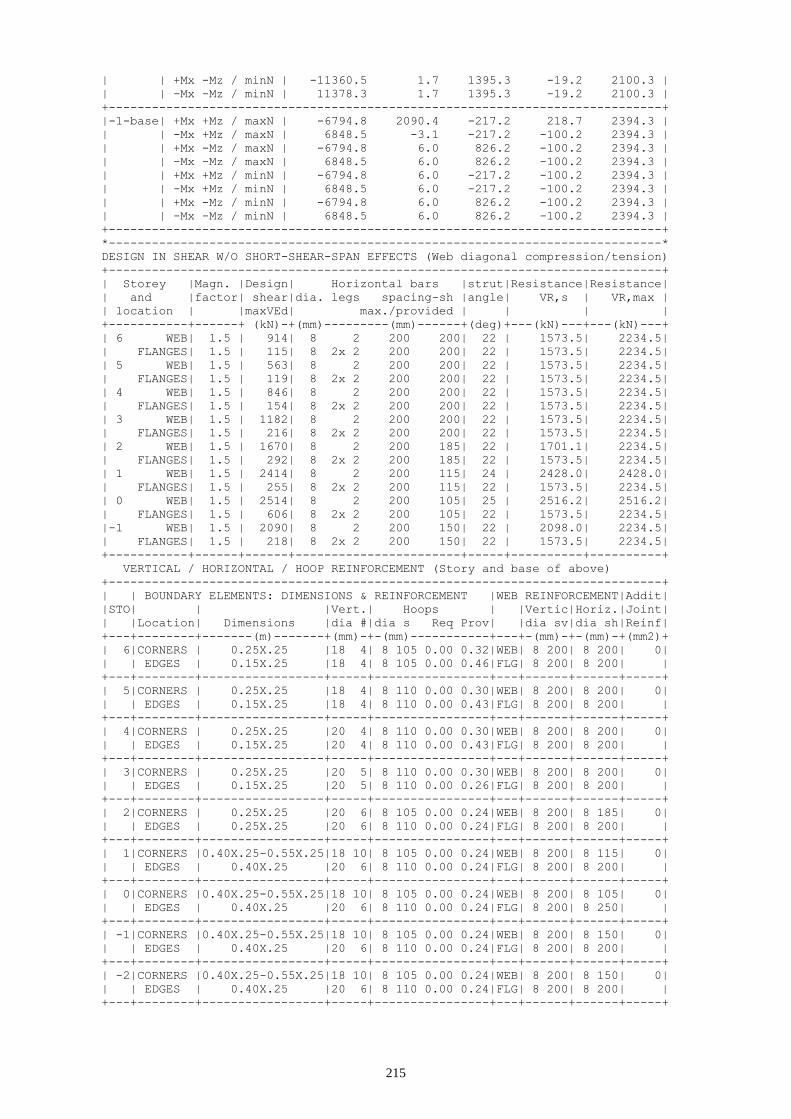
215
| | +Mx -Mz / minN | -11360.5 1.7 1395.3 -19.2 2100.3 |
| | -Mx -Mz / minN | 11378.3 1.7 1395.3 -19.2 2100.3 |
+-----------------------------------------------------------------------------+
|-1-base| +Mx +Mz / maxN | -6794.8 2090.4 -217.2 218.7 2394.3 |
| | -Mx +Mz / maxN | 6848.5 -3.1 -217.2 -100.2 2394.3 |
| | +Mx -Mz / maxN | -6794.8 6.0 826.2 -100.2 2394.3 |
| | -Mx -Mz / maxN | 6848.5 6.0 826.2 -100.2 2394.3 |
| | +Mx +Mz / minN | -6794.8 6.0 -217.2 -100.2 2394.3 |
| | -Mx +Mz / minN | 6848.5 6.0 -217.2 -100.2 2394.3 |
| | +Mx -Mz / minN | -6794.8 6.0 826.2 -100.2 2394.3 |
| | -Mx -Mz / minN | 6848.5 6.0 826.2 -100.2 2394.3 |
+-----------------------------------------------------------------------------+
*-----------------------------------------------------------------------------*
DESIGN IN SHEAR W/O SHORT-SHEAR-SPAN EFFECTS (Web diagonal compression/tension)
+-----------------------------------------------------------------------------+
| Storey |Magn. |Design| Horizontal bars |strut|Resistance|Resistance|
| and |factor| shear|dia. legs spacing-sh |angle| VR,s | VR,max |
| location | |maxVEd| max./provided | | | |
+-----------+------+ (kN)-+(mm)---------(mm)------+(deg)+---(kN)---+---(kN)---+
| 6 WEB| 1.5 | 914| 8 2 200 200| 22 | 1573.5| 2234.5|
| FLANGES| 1.5 | 115| 8 2x 2 200 200| 22 | 1573.5| 2234.5|
| 5 WEB| 1.5 | 563| 8 2 200 200| 22 | 1573.5| 2234.5|
| FLANGES| 1.5 | 119| 8 2x 2 200 200| 22 | 1573.5| 2234.5|
| 4 WEB| 1.5 | 846| 8 2 200 200| 22 | 1573.5| 2234.5|
| FLANGES| 1.5 | 154| 8 2x 2 200 200| 22 | 1573.5| 2234.5|
| 3 WEB| 1.5 | 1182| 8 2 200 200| 22 | 1573.5| 2234.5|
| FLANGES| 1.5 | 216| 8 2x 2 200 200| 22 | 1573.5| 2234.5|
| 2 WEB| 1.5 | 1670| 8 2 200 185| 22 | 1701.1| 2234.5|
| FLANGES| 1.5 | 292| 8 2x 2 200 185| 22 | 1573.5| 2234.5|
| 1 WEB| 1.5 | 2414| 8 2 200 115| 24 | 2428.0| 2428.0|
| FLANGES| 1.5 | 255| 8 2x 2 200 115| 22 | 1573.5| 2234.5|
| 0 WEB| 1.5 | 2514| 8 2 200 105| 25 | 2516.2| 2516.2|
| FLANGES| 1.5 | 606| 8 2x 2 200 105| 22 | 1573.5| 2234.5|
|-1 WEB| 1.5 | 2090| 8 2 200 150| 22 | 2098.0| 2234.5|
| FLANGES| 1.5 | 218| 8 2x 2 200 150| 22 | 1573.5| 2234.5|
+-----------+------+------+-----------------------+-----+----------+----------+
VERTICAL / HORIZONTAL / HOOP REINFORCEMENT (Story and base of above)
+-----------------------------------------------------------------------------+
| | BOUNDARY ELEMENTS: DIMENSIONS & REINFORCEMENT |WEB REINFORCEMENT|Addit|
|STO| | |Vert.| Hoops | |Vertic|Horiz.|Joint|
| |Location| Dimensions |dia #|dia s Req Prov| |dia sv|dia sh|Reinf|
+---+--------+-------(m)-------+(mm)-+-(mm)-----------+---+-(mm)-+-(mm)-+(mm2)+
| 6|CORNERS | 0.25X.25 |18 4| 8 105 0.00 0.32|WEB| 8 200| 8 200| 0|
| | EDGES | 0.15X.25 |18 4| 8 105 0.00 0.46|FLG| 8 200| 8 200| |
+---+--------+-----------------+-----+----------------+---+------+------+-----+
| 5|CORNERS | 0.25X.25 |18 4| 8 110 0.00 0.30|WEB| 8 200| 8 200| 0|
| | EDGES | 0.15X.25 |18 4| 8 110 0.00 0.43|FLG| 8 200| 8 200| |
+---+--------+-----------------+-----+----------------+---+------+------+-----+
| 4|CORNERS | 0.25X.25 |20 4| 8 110 0.00 0.30|WEB| 8 200| 8 200| 0|
| | EDGES | 0.15X.25 |20 4| 8 110 0.00 0.43|FLG| 8 200| 8 200| |
+---+--------+-----------------+-----+----------------+---+------+------+-----+
| 3|CORNERS | 0.25X.25 |20 5| 8 110 0.00 0.30|WEB| 8 200| 8 200| 0|
| | EDGES | 0.15X.25 |20 5| 8 110 0.00 0.26|FLG| 8 200| 8 200| |
+---+--------+-----------------+-----+----------------+---+------+------+-----+
| 2|CORNERS | 0.25X.25 |20 6| 8 105 0.00 0.24|WEB| 8 200| 8 185| 0|
| | EDGES | 0.25X.25 |20 6| 8 110 0.00 0.24|FLG| 8 200| 8 200| |
+---+--------+-----------------+-----+----------------+---+------+------+-----+
| 1|CORNERS |0.40X.25-0.55X.25|18 10| 8 105 0.00 0.24|WEB| 8 200| 8 115| 0|
| | EDGES | 0.40X.25 |20 6| 8 110 0.00 0.24|FLG| 8 200| 8 200| |
+---+--------+-----------------+-----+----------------+---+------+------+-----+
| 0|CORNERS |0.40X.25-0.55X.25|18 10| 8 105 0.00 0.24|WEB| 8 200| 8 105| 0|
| | EDGES | 0.40X.25 |20 6| 8 110 0.00 0.24|FLG| 8 200| 8 250| |
+---+--------+-----------------+-----+----------------+---+------+------+-----+
| -1|CORNERS |0.40X.25-0.55X.25|18 10| 8 105 0.00 0.24|WEB| 8 200| 8 150| 0|
| | EDGES | 0.40X.25 |20 6| 8 110 0.00 0.24|FLG| 8 200| 8 200| |
+---+--------+-----------------+-----+----------------+---+------+------+-----+
| -2|CORNERS |0.40X.25-0.55X.25|18 10| 8 105 0.00 0.24|WEB| 8 200| 8 150| 0|
| | EDGES | 0.40X.25 |20 6| 8 110 0.00 0.24|FLG| 8 200| 8 200| |
+---+--------+-----------------+-----+----------------+---+------+------+-----+

216
Fig. 9.7 Mx-My interaction diagram for wall W5 (stars indicate the design action effects)
-10000
-5000
0
5000
10000
-20000 -10000 0 10000 20000
Be
nd
ing m
om
ent M
z(k
Nm
)
Bending moment My (kNm)

217
Fig. 9.8 Longitudinal reinforcement of wall W5


219
10 Design of basement perimeter walls as deep foundation beams
10.1 Frame A
*-----------------------------------------------------------------------------*
*F.BEAMS: 1 2 3 4 5
*-----------------------------------------------------------------------------*
* Concrete: C25 - Long. Reinforcement: S500 - Stirrups: S500 - Cover: 35(mm) *
* Multiplier of Seismic Internal Forces : 1.4 *
*-----------------------------------------------------------------------------*
GEOMETRY - BENDING MOMENTS MEd - LONGITUDINAL REINFORCEMENT
+-----------------------------------------------------------------------------+
|Beam: 1|Length l: 6.00m|X-section Z/C | Depth h: 6.00m| Width bw: 0.30m |
|later. side| 45 bars |10 mm dia. | | |
|-----------+-----------------------------------------------------------------|
| |Top flange thickness (m): 0.18 (L end) 0.18 (centre) 0.18 (R end)|
|R end: 1|Bot flange thickness (m): 0.30 (L end) 0.30 (centre) 0.30 (R end)|
|-----------+-----------------------------------------------------------------|
| Location |Effect. | max MEd | Required | Beam bars | Provided |Flexural|
| |fl width| |steel area |Contin Addit |steel area|capacity|
|-----------+--(m)---+--(kNm)---+---(mm2)---+-------------+--(mm2)---+-(kNm)--|
|L end top | 1.00 | 398.1 | 379. | 2Φ18 -- | 763. |10787.1 |
|L end bot. | 0.48 | 382.8 | 379. | 2Φ18 -- | 509. | 9903.0 |
|midspan | 1.32 | -513.9 | 379. | 2Φ18 -- | 509. |10221.3 |
|R end top | 1.00 | 202.7 | 379. | 2Φ18 -- | 509. |10245.8 |
|R end bot. | 0.66 | 1924.8 | 379. | 2Φ18 6Φ18| 2036. |13742.7 |
+-----------------------------------------------------------------------------+
+-----------------------------------------------------------------------------+
|Beam: 2|Length l: 6.00m|X-section Z/C | Depth h: 6.00m| Width bw: 0.30m |
|later. side| 45 bars |10 mm dia. | | |
|-----------+-----------------------------------------------------------------|
| |Top flange thickness (m): 0.18 (L end) 0.18 (centre) 0.18 (R end)|
|R end: 2|Bot flange thickness (m): 0.30 (L end) 0.30 (centre) 0.30 (R end)|
|-----------+-----------------------------------------------------------------|
| Location |Effect. | max MEd | Required | Beam bars | Provided |Flexural|
| |fl width| |steel area |Contin Addit |steel area|capacity|
|-----------+--(m)---+--(kNm)---+---(mm2)---+-------------+--(mm2)---+-(kNm)--|
|L end top | 1.00 | 35.8 | 379. | 2Φ18 -- | 509. |10245.8 |
|L end bot. | 0.66 | 1686.7 | 379. | 2Φ18 6Φ18| 2036. |13742.7 |
|midspan | 1.14 | -228.9 | 379. | 2Φ18 -- | 509. |10187.3 |
|R end top | 1.00 | 213.9 | 379. | 2Φ18 -- | 509. |10245.8 |
|R end bot. | 0.66 | 1431.3 | 379. | 2Φ18 6Φ18| 2036. |13742.7 |
+-----------------------------------------------------------------------------+
+-----------------------------------------------------------------------------+
|Beam: 3|Length l: 6.00m|X-section Z/C | Depth h: 6.00m| Width bw: 0.30m |
|later. side| 45 bars |10 mm dia. | | |
|-----------+-----------------------------------------------------------------|
| |Top flange thickness (m): 0.18 (L end) 0.18 (centre) 0.18 (R end)|
|R end: 3|Bot flange thickness (m): 0.30 (L end) 0.30 (centre) 0.30 (R end)|
|-----------+-----------------------------------------------------------------|
| Location |Effect. | max MEd | Required | Beam bars | Provided |Flexural|
| |fl width| |steel area |Contin Addit |steel area|capacity|
|-----------+--(m)---+--(kNm)---+---(mm2)---+-------------+--(mm2)---+-(kNm)--|
|L end top | 1.00 | 212.9 | 379. | 2Φ18 -- | 509. |10245.8 |
|L end bot. | 0.66 | 1423.3 | 379. | 2Φ18 6Φ18| 2036. |13742.7 |
|midspan | 1.14 | -388.5 | 379. | 2Φ18 -- | 509. |10187.3 |
|R end top | 1.00 | 213.8 | 379. | 2Φ18 -- | 509. |10245.8 |
|R end bot. | 0.66 | 1422.3 | 379. | 2Φ18 6Φ18| 2036. |13742.7 |
+-----------------------------------------------------------------------------+
+-----------------------------------------------------------------------------+
|Beam: 4|Length l: 6.00m|X-section Z/C | Depth h: 6.00m| Width bw: 0.30m |
|later. side| 45 bars |10 mm dia. | | |
|-----------+-----------------------------------------------------------------|
| |Top flange thickness (m): 0.18 (L end) 0.18 (centre) 0.18 (R end)|
|R end: 4|Bot flange thickness (m): 0.30 (L end) 0.30 (centre) 0.30 (R end)|
|-----------+-----------------------------------------------------------------|
| Location |Effect. | max MEd | Required | Beam bars | Provided |Flexural|
| |fl width| |steel area |Contin Addit |steel area|capacity|
|-----------+--(m)---+--(kNm)---+---(mm2)---+-------------+--(mm2)---+-(kNm)--|
|L end top | 1.00 | 214.0 | 379. | 2Φ18 -- | 509. |10245.8 |

220
|L end bot. | 0.66 | 1431.2 | 379. | 2Φ18 6Φ18| 2036. |13742.7 |
|midspan | 1.14 | -252.3 | 379. | 2Φ18 -- | 509. |10187.3 |
|R end top | 1.00 | 36.5 | 379. | 2Φ18 -- | 509. |10245.8 |
|R end bot. | 0.66 | 1686.0 | 379. | 2Φ18 6Φ18| 2036. |13742.7 |
+-----------------------------------------------------------------------------+
+-----------------------------------------------------------------------------+
|Beam: 5|Length l: 6.00m|X-section Z/C | Depth h: 6.00m| Width bw: 0.30m |
|later. side| 45 bars |10 mm dia. | | |
|-----------+-----------------------------------------------------------------|
| |Top flange thickness (m): 0.18 (L end) 0.18 (centre) 0.18 (R end)|
|R end: 5|Bot flange thickness (m): 0.30 (L end) 0.30 (centre) 0.30 (R end)|
|-----------+-----------------------------------------------------------------|
| Location |Effect. | max MEd | Required | Beam bars | Provided |Flexural|
| |fl width| |steel area |Contin Addit |steel area|capacity|
|-----------+--(m)---+--(kNm)---+---(mm2)---+-------------+--(mm2)---+-(kNm)--|
|L end top | 1.00 | 202.6 | 379. | 2Φ18 -- | 509. |10245.8 |
|L end bot. | 0.66 | 1924.9 | 379. | 2Φ18 6Φ18| 2036. |13742.7 |
|midspan | 1.32 | -593.5 | 379. | 2Φ18 -- | 509. |10221.3 |
|R end top | 1.00 | 398.4 | 379. | 2Φ18 -- | 763. |10787.1 |
|R end bot. | 0.48 | 382.5 | 379. | 2Φ18 -- | 509. | 9903.0 |
+-----------------------------------------------------------------------------+
+-----------------------------------------------------------------------------+
SLS CHECKS: STRESS LIMITS, CRACK WIDTH CONTROL FOR Wmax=0.3mm & min STEEL AREA
+---------+--------------------------+------------------------------+---------+
|Beam: 1 |
+---------+--------------------------+------------------------------+---------+
|Location | Characteristic loads G+Q | Quasi-permanent loads G+ψ2Q |Steel for|
| |Moment steel concrete |Moment concrete Crack | cracking|
| | stress/fyk stress/fck| stress/fck spacing width |min provd|
|---------+-(kNm)--------------------+-(kNm)---------------(mm)-----+--(mm2)--|
|L end top| 13.3 0.001 0.000 | 7.6 0.000 293.8 0.00 | 737 763|
| Midspan |-429.0 0.000 0.000 |-386.0 0.000 0.0 0.00 | 174 508|
|R end bot|1021.0 0.061 0.019 | 861.1 0.016 200.2 0.02 |1860 2035|
|web skin bars: Φ10/130 mm | 877.8 0.03 | |
+---------+--------------------------+------------------------------+---------+
|Beam: 2 |
+---------+--------------------------+------------------------------+---------+
|Location | Characteristic loads G+Q | Quasi-permanent loads G+ψ2Q |Steel for|
| |Moment steel concrete |Moment concrete Crack | cracking|
| | stress/fyk stress/fck| stress/fck spacing width |min provd|
|---------+-(kNm)--------------------+-(kNm)---------------(mm)-----+--(mm2)--|
|L end bot| 974.8 0.041 0.012 | 825.5 0.010 412.1 0.02 |1862 2035|
| Midspan |-194.2 0.000 0.000 |-182.2 0.000 0.0 0.00 | 174 508|
|R end bot| 715.5 0.030 0.009 | 608.7 0.008 200.2 0.01 |1862 2035|
|web skin bars: Φ10/130 mm | 877.8 0.02 | |
+---------+--------------------------+------------------------------+---------+
|Beam: 3 |
+---------+--------------------------+------------------------------+---------+
|Location | Characteristic loads G+Q | Quasi-permanent loads G+ψ2Q |Steel for|
| |Moment steel concrete |Moment concrete Crack | cracking|
| | stress/fyk stress/fck| stress/fck spacing width |min provd|
|---------+-(kNm)--------------------+-(kNm)---------------(mm)-----+--(mm2)--|
|L end bot| 710.1 0.030 0.009 | 605.2 0.008 412.1 0.02 |1862 2035|
| Midspan |-323.0 0.000 0.000 |-287.7 0.000 0.0 0.00 | 174 508|
|R end bot| 709.2 0.030 0.009 | 604.2 0.008 200.2 0.01 |1862 2035|
|web skin bars: Φ10/130 mm | 877.8 0.02 | |
+---------+--------------------------+------------------------------+---------+
|Beam: 4 |
+---------+--------------------------+------------------------------+---------+
|Location | Characteristic loads G+Q | Quasi-permanent loads G+ψ2Q |Steel for|
| |Moment steel concrete |Moment concrete Crack | cracking|
| | stress/fyk stress/fck| stress/fck spacing width |min provd|
|---------+-(kNm)--------------------+-(kNm)---------------(mm)-----+--(mm2)--|
|L end bot| 715.4 0.030 0.009 | 608.6 0.008 412.1 0.02 |1862 2035|
| Midspan |-212.5 0.000 0.000 |-195.7 0.000 0.0 0.00 | 174 508|
|R end bot| 974.0 0.041 0.012 | 824.8 0.010 200.2 0.01 |1862 2035|
|web skin bars: Φ10/130 mm | 877.8 0.02 | |
+---------+--------------------------+------------------------------+---------+
|Beam: 5 |
+---------+--------------------------+------------------------------+---------+
|Location | Characteristic loads G+Q | Quasi-permanent loads G+ψ2Q |Steel for|
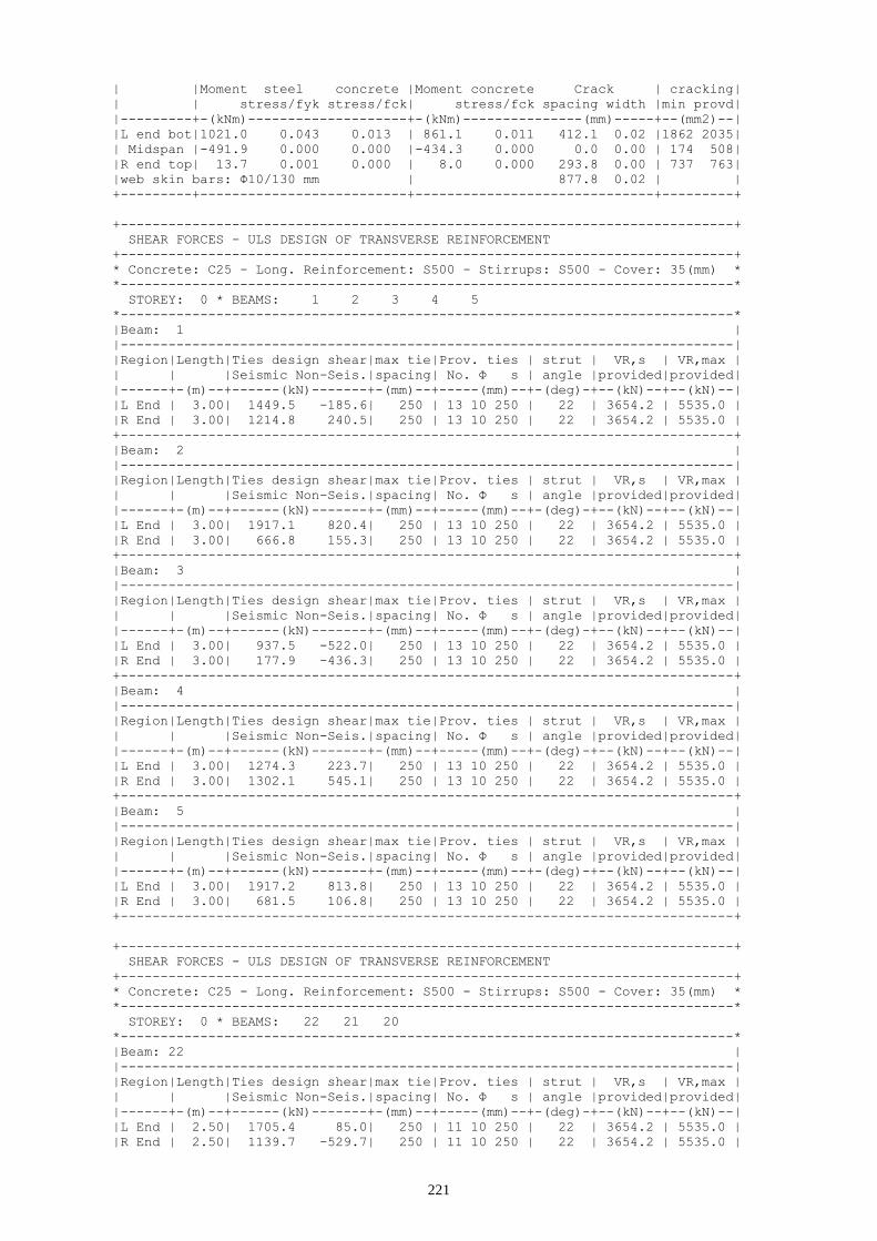
221
| |Moment steel concrete |Moment concrete Crack | cracking|
| | stress/fyk stress/fck| stress/fck spacing width |min provd|
|---------+-(kNm)--------------------+-(kNm)---------------(mm)-----+--(mm2)--|
|L end bot|1021.0 0.043 0.013 | 861.1 0.011 412.1 0.02 |1862 2035|
| Midspan |-491.9 0.000 0.000 |-434.3 0.000 0.0 0.00 | 174 508|
|R end top| 13.7 0.001 0.000 | 8.0 0.000 293.8 0.00 | 737 763|
|web skin bars: Φ10/130 mm | 877.8 0.02 | |
+---------+--------------------------+------------------------------+---------+
+-----------------------------------------------------------------------------+
SHEAR FORCES - ULS DESIGN OF TRANSVERSE REINFORCEMENT
+-----------------------------------------------------------------------------+
* Concrete: C25 - Long. Reinforcement: S500 - Stirrups: S500 - Cover: 35(mm) *
*-----------------------------------------------------------------------------*
STOREY: 0 * BEAMS: 1 2 3 4 5
*-----------------------------------------------------------------------------*
|Beam: 1 |
|-----------------------------------------------------------------------------|
|Region|Length|Ties design shear|max tie|Prov. ties | strut | VR,s | VR,max |
| | |Seismic Non-Seis.|spacing| No. Φ s | angle |provided|provided|
|------+-(m)--+------(kN)-------+-(mm)--+-----(mm)--+-(deg)-+--(kN)--+--(kN)--|
|L End | 3.00| 1449.5 -185.6| 250 | 13 10 250 | 22 | 3654.2 | 5535.0 |
|R End | 3.00| 1214.8 240.5| 250 | 13 10 250 | 22 | 3654.2 | 5535.0 |
+-----------------------------------------------------------------------------+
|Beam: 2 |
|-----------------------------------------------------------------------------|
|Region|Length|Ties design shear|max tie|Prov. ties | strut | VR,s | VR,max |
| | |Seismic Non-Seis.|spacing| No. Φ s | angle |provided|provided|
|------+-(m)--+------(kN)-------+-(mm)--+-----(mm)--+-(deg)-+--(kN)--+--(kN)--|
|L End | 3.00| 1917.1 820.4| 250 | 13 10 250 | 22 | 3654.2 | 5535.0 |
|R End | 3.00| 666.8 155.3| 250 | 13 10 250 | 22 | 3654.2 | 5535.0 |
+-----------------------------------------------------------------------------+
|Beam: 3 |
|-----------------------------------------------------------------------------|
|Region|Length|Ties design shear|max tie|Prov. ties | strut | VR,s | VR,max |
| | |Seismic Non-Seis.|spacing| No. Φ s | angle |provided|provided|
|------+-(m)--+------(kN)-------+-(mm)--+-----(mm)--+-(deg)-+--(kN)--+--(kN)--|
|L End | 3.00| 937.5 -522.0| 250 | 13 10 250 | 22 | 3654.2 | 5535.0 |
|R End | 3.00| 177.9 -436.3| 250 | 13 10 250 | 22 | 3654.2 | 5535.0 |
+-----------------------------------------------------------------------------+
|Beam: 4 |
|-----------------------------------------------------------------------------|
|Region|Length|Ties design shear|max tie|Prov. ties | strut | VR,s | VR,max |
| | |Seismic Non-Seis.|spacing| No. Φ s | angle |provided|provided|
|------+-(m)--+------(kN)-------+-(mm)--+-----(mm)--+-(deg)-+--(kN)--+--(kN)--|
|L End | 3.00| 1274.3 223.7| 250 | 13 10 250 | 22 | 3654.2 | 5535.0 |
|R End | 3.00| 1302.1 545.1| 250 | 13 10 250 | 22 | 3654.2 | 5535.0 |
+-----------------------------------------------------------------------------+
|Beam: 5 |
|-----------------------------------------------------------------------------|
|Region|Length|Ties design shear|max tie|Prov. ties | strut | VR,s | VR,max |
| | |Seismic Non-Seis.|spacing| No. Φ s | angle |provided|provided|
|------+-(m)--+------(kN)-------+-(mm)--+-----(mm)--+-(deg)-+--(kN)--+--(kN)--|
|L End | 3.00| 1917.2 813.8| 250 | 13 10 250 | 22 | 3654.2 | 5535.0 |
|R End | 3.00| 681.5 106.8| 250 | 13 10 250 | 22 | 3654.2 | 5535.0 |
+-----------------------------------------------------------------------------+
+-----------------------------------------------------------------------------+
SHEAR FORCES - ULS DESIGN OF TRANSVERSE REINFORCEMENT
+-----------------------------------------------------------------------------+
* Concrete: C25 - Long. Reinforcement: S500 - Stirrups: S500 - Cover: 35(mm) *
*-----------------------------------------------------------------------------*
STOREY: 0 * BEAMS: 22 21 20
*-----------------------------------------------------------------------------*
|Beam: 22 |
|-----------------------------------------------------------------------------|
|Region|Length|Ties design shear|max tie|Prov. ties | strut | VR,s | VR,max |
| | |Seismic Non-Seis.|spacing| No. Φ s | angle |provided|provided|
|------+-(m)--+------(kN)-------+-(mm)--+-----(mm)--+-(deg)-+--(kN)--+--(kN)--|
|L End | 2.50| 1705.4 85.0| 250 | 11 10 250 | 22 | 3654.2 | 5535.0 |
|R End | 2.50| 1139.7 -529.7| 250 | 11 10 250 | 22 | 3654.2 | 5535.0 |

222
+-----------------------------------------------------------------------------+
|Beam: 21 |
|-----------------------------------------------------------------------------|
|Region|Length|Ties design shear|max tie|Prov. ties | strut | VR,s | VR,max |
| | |Seismic Non-Seis.|spacing| No. Φ s | angle |provided|provided|
|------+-(m)--+------(kN)-------+-(mm)--+-----(mm)--+-(deg)-+--(kN)--+--(kN)--|
|L End | 2.50| 134.7 134.1| 250 | 11 10 250 | 22 | 3654.2 | 5535.0 |
|R End | 2.50| 1960.7 1567.6| 250 | 11 10 250 | 22 | 3654.2 | 5535.0 |
+-----------------------------------------------------------------------------+
|Beam: 20 |
|-----------------------------------------------------------------------------|
|Region|Length|Ties design shear|max tie|Prov. ties | strut | VR,s | VR,max |
| | |Seismic Non-Seis.|spacing| No. Φ s | angle |provided|provided|
|------+-(m)--+------(kN)-------+-(mm)--+-----(mm)--+-(deg)-+--(kN)--+--(kN)--|
|L End | 3.50| 562.5 1897.5| 250 | 15 10 250 | 22 | 3654.2 | 5535.0 |
|R End | 3.50| 1995.3 1864.1| 250 | 15 10 250 | 22 | 3654.2 | 5535.0 |
+-----------------------------------------------------------------------------+
10.2 Frame 1
*-----------------------------------------------------------------------------*
*F.BEAMS: 22 21 20
*-----------------------------------------------------------------------------*
* Concrete: C25 - Long. Reinforcement: S500 - Stirrups: S500 - Cover: 35(mm) *
* Multiplier of Seismic Internal Forces : 1.4 *
*-----------------------------------------------------------------------------*
GEOMETRY - BENDING MOMENTS MEd - LONGITUDINAL REINFORCEMENT
+-----------------------------------------------------------------------------+
|Beam: 22|Length l: 5.00m|X-section Z/C | Depth h: 6.00m| Width bw: 0.30m |
|later. side| 45 bars |10 mm dia. | | |
|-----------+-----------------------------------------------------------------|
| |Top flange thickness (m): 0.18 (L end) 0.18 (centre) 0.18 (R end)|
|R end: 22|Bot flange thickness (m): 0.30 (L end) 0.30 (centre) 0.30 (R end)|
|-----------+-----------------------------------------------------------------|
| Location |Effect. | max MEd | Required | Beam bars | Provided |Flexural|
| |fl width| |steel area |Contin Addit |steel area|capacity|
|-----------+--(m)---+--(kNm)---+---(mm2)---+-------------+--(mm2)---+-(kNm)--|
|L end top | 1.00 | 1807.8 | 379. | 2Φ18 -- | 509. |10245.8 |
|L end bot. | 0.51 | 3190.4 | 379. | 2Φ18 6Φ18| 2036. |13573.5 |
|midspan | 1.49 | -366.8 | 379. | 2Φ18 -- | 509. |10246.1 |
|R end top | 1.00 | 477.5 | 379. | 2Φ18 -- | 1018. |11420.7 |
|R end bot. | 0.72 | 278.9 | 379. | 2Φ18 -- | 509. |10094.6 |
+-----------------------------------------------------------------------------+
+-----------------------------------------------------------------------------+
|Beam: 21|Length l: 5.00m|X-section Z/C | Depth h: 6.00m| Width bw: 0.30m |
|later. side| 45 bars |10 mm dia. | | |
|-----------+-----------------------------------------------------------------|
| |Top flange thickness (m): 0.18 (L end) 0.18 (centre) 0.18 (R end)|
|R end: 21|Bot flange thickness (m): 0.30 (L end) 0.30 (centre) 0.30 (R end)|
|-----------+-----------------------------------------------------------------|
| Location |Effect. | max MEd | Required | Beam bars | Provided |Flexural|
| |fl width| |steel area |Contin Addit |steel area|capacity|
|-----------+--(m)---+--(kNm)---+---(mm2)---+-------------+--(mm2)---+-(kNm)--|
|L end top | 1.00 | 400.1 | 379. | 2Φ18 -- | 509. |10245.8 |
|L end bot. | 0.72 | 1551.3 | 379. | 2Φ18 6Φ18| 2036. |13792.1 |
|midspan | 1.28 | 432.3 | 379. | 2Φ18 6Φ18| 2036. |14038.3 |
|R end top | 1.00 | 2941.2 | 379. | 2Φ18 -- | 509. |10245.8 |
|R end bot. | 0.72 | 4936.1 | 379. | 2Φ18 6Φ18| 2036. |13792.1 |
+-----------------------------------------------------------------------------+
+-----------------------------------------------------------------------------+
|Beam: 20|Length l: 7.00m|X-section Z/C | Depth h: 6.00m| Width bw: 0.30m |
|later. side| 45 bars |10 mm dia. | | |
|-----------+-----------------------------------------------------------------|
| |Top flange thickness (m): 0.18 (L end) 0.18 (centre) 0.18 (R end)|
|R end: 20|Bot flange thickness (m): 0.30 (L end) 0.30 (centre) 0.30 (R end)|
|-----------+-----------------------------------------------------------------|
| Location |Effect. | max MEd | Required | Beam bars | Provided |Flexural|
| |fl width| |steel area |Contin Addit |steel area|capacity|
|-----------+--(m)---+--(kNm)---+---(mm2)---+-------------+--(mm2)---+-(kNm)--|
|L end top | 1.00 | 670.2 | 379. | 2Φ18 -- | 1018. |11420.7 |

223
|L end bot. | 0.72 | 466.0 | 379. | 2Φ18 -- | 509. |10094.6 |
|midspan | 1.49 | -200.0 | 379. | 2Φ18 -- | 509. |10246.1 |
|R end top | 1.00 | 1157.4 | 379. | 2Φ18 -- | 509. |10245.8 |
|R end bot. | 0.51 | 2697.3 | 379. | 2Φ18 6Φ18| 2036. |13573.5 |
+-----------------------------------------------------------------------------+
+-----------------------------------------------------------------------------+
SLS CHECKS: STRESS LIMITS, CRACK WIDTH CONTROL FOR Wmax=0.3mm & min STEEL AREA
+---------+--------------------------+------------------------------+---------+
|Beam: 22 |
+---------+--------------------------+------------------------------+---------+
|Location | Characteristic loads G+Q | Quasi-permanent loads G+ψ2Q |Steel for|
| |Moment steel concrete |Moment concrete Crack | cracking|
| | stress/fyk stress/fck| stress/fck spacing width |min provd|
|---------+-(kNm)--------------------+-(kNm)---------------(mm)-----+--(mm2)--|
|L end bot| 759.1 0.043 0.013 | 691.3 0.012 412.1 0.02 |1861 2035|
| Midspan |-298.1 0.000 0.000 |-249.2 0.000 0.0 0.00 | 174 508|
|R end top| 110.0 0.005 0.001 | 99.3 0.001 252.5 0.00 | 893 1017|
|web skin bars: Φ10/130 mm | 877.8 0.03 | |
+---------+--------------------------+------------------------------+---------+
|Beam: 21 |
+---------+--------------------------+------------------------------+---------+
|Location | Characteristic loads G+Q | Quasi-permanent loads G+ψ2Q |Steel for|
| |Moment steel concrete |Moment concrete Crack | cracking|
| | stress/fyk stress/fck| stress/fck spacing width |min provd|
|---------+-(kNm)--------------------+-(kNm)---------------(mm)-----+--(mm2)--|
|L end bot| 671.8 0.026 0.008 | 575.6 0.006 412.1 0.01 |1863 2035|
| Midspan | 332.0 0.007 0.002 | 294.9 0.001 200.2 0.00 |1867 2035|
|R end bot|1115.3 0.043 0.013 | 997.4 0.011 200.2 0.01 |1863 2035|
|web skin bars: Φ10/130 mm | 877.8 0.03 | |
+---------+--------------------------+------------------------------+---------+
|Beam: 20 |
+---------+--------------------------+------------------------------+---------+
|Location | Characteristic loads G+Q | Quasi-permanent loads G+ψ2Q |Steel for|
| |Moment steel concrete |Moment concrete Crack | cracking|
| | stress/fyk stress/fck| stress/fck spacing width |min provd|
|---------+-(kNm)--------------------+-(kNm)---------------(mm)-----+--(mm2)--|
|L end top| 114.7 0.006 0.001 | 102.1 0.001 252.5 0.00 | 893 1017|
| Midspan |-165.9 0.000 0.000 |-146.8 0.000 0.0 0.00 | 174 508|
|R end bot| 889.4 0.034 0.010 | 770.0 0.009 200.2 0.01 |1863 2035|
|web skin bars: Φ10/130 mm | 877.8 0.02 | |
+---------+--------------------------+------------------------------+---------+
10.3 Frame D
*-----------------------------------------------------------------------------*
*F.BEAMS: -1 15 16 17 18 19
*-----------------------------------------------------------------------------*
* Concrete: C25 - Long. Reinforcement: S500 - Stirrups: S500 - Cover: 35(mm) *
* Multiplier of Seismic Internal Forces : 1.4 *
*-----------------------------------------------------------------------------*
GEOMETRY - BENDING MOMENTS MEd - LONGITUDINAL REINFORCEMENT
+-----------------------------------------------------------------------------+
|Beam: 15|Length l: 6.00m|X-section Z/C | Depth h: 6.00m| Width bw: 0.30m |
|later. side| 45 bars |10 mm dia. | | |
|-----------+-----------------------------------------------------------------|
| |Top flange thickness (m): 0.18 (L end) 0.18 (centre) 0.18 (R end)|
|R end: 15|Bot flange thickness (m): 0.30 (L end) 0.30 (centre) 0.30 (R end)|
|-----------+-----------------------------------------------------------------|
| Location |Effect. | max MEd | Required | Beam bars | Provided |Flexural|
| |fl width| |steel area |Contin Addit |steel area|capacity|
|-----------+--(m)---+--(kNm)---+---(mm2)---+-------------+--(mm2)---+-(kNm)--|
|L end top | 1.00 | 302.1 | 379. | 2Φ18 -- | 509. |10245.8 |
|L end bot. | 0.48 | 330.8 | 379. | 2Φ18 6Φ18| 2036. |13528.2 |
|midspan | 1.32 | -202.6 | 379. | 2Φ18 -- | 509. |10221.3 |
|R end top | 1.00 | 922.6 | 379. | 2Φ18 -- | 509. |10245.8 |
|R end bot. | 0.66 | 1074.1 | 379. | 2Φ18 6Φ18| 2036. |13742.7 |
+-----------------------------------------------------------------------------+
+-----------------------------------------------------------------------------+
|Beam: 16|Length l: 6.00m|X-section Z/C | Depth h: 6.00m| Width bw: 0.30m |
|later. side| 45 bars |10 mm dia. | | |

224
|-----------+-----------------------------------------------------------------|
| |Top flange thickness (m): 0.18 (L end) 0.18 (centre) 0.18 (R end)|
|R end: 16|Bot flange thickness (m): 0.30 (L end) 0.30 (centre) 0.30 (R end)|
|-----------+-----------------------------------------------------------------|
| Location |Effect. | max MEd | Required | Beam bars | Provided |Flexural|
| |fl width| |steel area |Contin Addit |steel area|capacity|
|-----------+--(m)---+--(kNm)---+---(mm2)---+-------------+--(mm2)---+-(kNm)--|
|L end top | 1.00 | 749.3 | 379. | 2Φ18 -- | 509. |10245.8 |
|L end bot. | 0.66 | 916.6 | 379. | 2Φ18 6Φ18| 2036. |13742.7 |
|midspan | 1.14 | -127.1 | 379. | 2Φ18 -- | 509. |10187.3 |
|R end top | 1.00 | 670.0 | 379. | 2Φ18 -- | 509. |10245.8 |
|R end bot. | 0.66 | 880.1 | 379. | 2Φ18 6Φ18| 2036. |13742.7 |
+-----------------------------------------------------------------------------+
+-----------------------------------------------------------------------------+
|Beam: 17|Length l: 6.00m|X-section Z/C | Depth h: 6.00m| Width bw: 0.30m |
|later. side| 45 bars |10 mm dia. | | |
|-----------+-----------------------------------------------------------------|
| |Top flange thickness (m): 0.18 (L end) 0.18 (centre) 0.18 (R end)|
|R end: 17|Bot flange thickness (m): 0.30 (L end) 0.30 (centre) 0.30 (R end)|
|-----------+-----------------------------------------------------------------|
| Location |Effect. | max MEd | Required | Beam bars | Provided |Flexural|
| |fl width| |steel area |Contin Addit |steel area|capacity|
|-----------+--(m)---+--(kNm)---+---(mm2)---+-------------+--(mm2)---+-(kNm)--|
|L end top | 1.00 | 639.9 | 379. | 2Φ18 -- | 509. |10245.8 |
|L end bot. | 0.66 | 853.6 | 379. | 2Φ18 6Φ18| 2036. |13742.7 |
|midspan | 1.14 | -110.0 | 379. | 2Φ18 -- | 509. |10187.3 |
|R end top | 1.00 | 640.2 | 379. | 2Φ18 -- | 509. |10245.8 |
|R end bot. | 0.66 | 853.3 | 379. | 2Φ18 6Φ18| 2036. |13742.7 |
+-----------------------------------------------------------------------------+
+-----------------------------------------------------------------------------+
|Beam: 18|Length l: 6.00m|X-section Z/C | Depth h: 6.00m| Width bw: 0.30m |
|later. side| 45 bars |10 mm dia. | | |
|-----------+-----------------------------------------------------------------|
| |Top flange thickness (m): 0.18 (L end) 0.18 (centre) 0.18 (R end)|
|R end: 18|Bot flange thickness (m): 0.30 (L end) 0.30 (centre) 0.30 (R end)|
|-----------+-----------------------------------------------------------------|
| Location |Effect. | max MEd | Required | Beam bars | Provided |Flexural|
| |fl width| |steel area |Contin Addit |steel area|capacity|
|-----------+--(m)---+--(kNm)---+---(mm2)---+-------------+--(mm2)---+-(kNm)--|
|L end top | 1.00 | 907.6 | 379. | 2Φ18 -- | 1018. |11420.7 |
|L end bot. | 0.66 | 722.6 | 379. | 2Φ18 -- | 509. |10065.4 |
|midspan | 1.14 | 130.2 | 379. | 2Φ18 6Φ18| 2036. |13998.4 |
|R end top | 1.00 | 669.6 | 379. | 2Φ18 -- | 509. |10245.8 |
|R end bot. | 0.66 | 880.6 | 379. | 2Φ18 6Φ18| 2036. |13742.7 |
+-----------------------------------------------------------------------------+
+-----------------------------------------------------------------------------+
|Beam: 19|Length l: 6.00m|X-section Z/C | Depth h: 6.00m| Width bw: 0.30m |
|later. side| 45 bars |10 mm dia. | | |
|-----------+-----------------------------------------------------------------|
| |Top flange thickness (m): 0.18 (L end) 0.18 (centre) 0.18 (R end)|
|R end: 19|Bot flange thickness (m): 0.30 (L end) 0.30 (centre) 0.30 (R end)|
|-----------+-----------------------------------------------------------------|
| Location |Effect. | max MEd | Required | Beam bars | Provided |Flexural|
| |fl width| |steel area |Contin Addit |steel area|capacity|
|-----------+--(m)---+--(kNm)---+---(mm2)---+-------------+--(mm2)---+-(kNm)--|
|L end top | 1.00 | 922.5 | 379. | 2Φ18 -- | 509. |10245.8 |
|L end bot. | 0.66 | 1074.2 | 379. | 2Φ18 6Φ18| 2036. |13742.7 |
|midspan | 1.32 | -186.8 | 379. | 2Φ18 -- | 509. |10221.3 |
|R end top | 1.00 | 302.4 | 379. | 2Φ18 -- | 509. |10245.8 |
|R end bot. | 0.48 | 330.5 | 379. | 2Φ18 6Φ18| 2036. |13528.2 |
+-----------------------------------------------------------------------------+
+-----------------------------------------------------------------------------+
SLS CHECKS: STRESS LIMITS, CRACK WIDTH CONTROL FOR Wmax=0.3mm & min STEEL AREA
+---------+--------------------------+------------------------------+---------+
|Beam: 15 |
+---------+--------------------------+------------------------------+---------+
|Location | Characteristic loads G+Q | Quasi-permanent loads G+ψ2Q |Steel for|
| |Moment steel concrete |Moment concrete Crack | cracking|
| | stress/fyk stress/fck| stress/fck spacing width |min provd|
|---------+-(kNm)--------------------+-(kNm)---------------(mm)-----+--(mm2)--|
|L end bot| 15.4 0.001 0.000 | 14.4 0.000 412.1 0.00 |1860 2035|

225
| Midspan |-167.8 0.000 0.000 |-147.9 0.000 0.0 0.00 | 174 508|
|R end bot| 95.9 0.006 0.002 | 75.8 0.001 200.2 0.00 |1860 2035|
|web skin bars: Φ10/130 mm | 877.8 0.00 | |
+---------+--------------------------+------------------------------+---------+
|Beam: 16 |
+---------+--------------------------+------------------------------+---------+
|Location | Characteristic loads G+Q | Quasi-permanent loads G+ψ2Q |Steel for|
| |Moment steel concrete |Moment concrete Crack | cracking|
| | stress/fyk stress/fck| stress/fck spacing width |min provd|
|---------+-(kNm)--------------------+-(kNm)---------------(mm)-----+--(mm2)--|
|L end bot| 103.3 0.004 0.001 | 83.7 0.001 412.1 0.00 |1862 2035|
| Midspan |-106.2 0.000 0.000 | -95.9 0.000 0.0 0.00 | 174 508|
|R end bot| 129.3 0.005 0.002 | 105.1 0.001 200.2 0.00 |1862 2035|
|web skin bars: Φ10/130 mm | 877.8 0.00 | |
+---------+--------------------------+------------------------------+---------+
|Beam: 17 |
+---------+--------------------------+------------------------------+---------+
|Location | Characteristic loads G+Q | Quasi-permanent loads G+ψ2Q |Steel for|
| |Moment steel concrete |Moment concrete Crack | cracking|
| | stress/fyk stress/fck| stress/fck spacing width |min provd|
|---------+-(kNm)--------------------+-(kNm)---------------(mm)-----+--(mm2)--|
|L end bot| 130.8 0.006 0.002 | 106.8 0.001 412.1 0.00 |1862 2035|
| Midspan | -91.8 0.000 0.000 | -82.7 0.000 0.0 0.00 | 174 508|
|R end bot| 130.5 0.006 0.002 | 106.6 0.001 200.2 0.00 |1862 2035|
|web skin bars: Φ10/130 mm | 877.8 0.00 | |
+---------+--------------------------+------------------------------+---------+
|Beam: 18 |
+---------+--------------------------+------------------------------+---------+
|Location | Characteristic loads G+Q | Quasi-permanent loads G+ψ2Q |Steel for|
| |Moment steel concrete |Moment concrete Crack | cracking|
| | stress/fyk stress/fck| stress/fck spacing width |min provd|
|---------+-(kNm)--------------------+-(kNm)---------------(mm)-----+--(mm2)--|
|L end top| 103.4 0.005 0.001 | 92.5 0.001 253.9 0.00 | 867 1017|
| Midspan | 102.6 0.002 0.001 | 83.0 0.000 200.2 0.00 |1866 2035|
|R end bot| 129.8 0.006 0.002 | 105.5 0.001 200.2 0.00 |1862 2035|
|web skin bars: Φ10/130 mm | 877.8 0.00 | |
+---------+--------------------------+------------------------------+---------+
|Beam: 19 |
+---------+--------------------------+------------------------------+---------+
|Location | Characteristic loads G+Q | Quasi-permanent loads G+ψ2Q |Steel for|
| |Moment steel concrete |Moment concrete Crack | cracking|
| | stress/fyk stress/fck| stress/fck spacing width |min provd|
|---------+-(kNm)--------------------+-(kNm)---------------(mm)-----+--(mm2)--|
|L end bot| 96.0 0.004 0.001 | 75.8 0.001 412.1 0.00 |1862 2035|
| Midspan |-154.1 0.000 0.000 |-134.3 0.000 0.0 0.00 | 174 508|
|R end bot| 15.1 0.001 0.000 | 14.1 0.000 200.2 0.00 |1862 2035|
|web skin bars: Φ10/130 mm | 877.8 0.00 | |
+---------+--------------------------+------------------------------+---------+
+-----------------------------------------------------------------------------+
+-----------------------------------------------------------------------------+
SHEAR FORCES - ULS DESIGN OF TRANSVERSE REINFORCEMENT
+-----------------------------------------------------------------------------+
* Concrete: C25 - Long. Reinforcement: S500 - Stirrups: S500 - Cover: 35(mm) *
*-----------------------------------------------------------------------------*
STOREY: 0 * BEAMS: 15 16 17 17 18
*-----------------------------------------------------------------------------*
|Beam: 15 |
|-----------------------------------------------------------------------------|
|Region|Length|Ties design shear|max tie|Prov. ties | strut | VR,s | VR,max |
| | |Seismic Non-Seis.|spacing| No. Φ s | angle |provided|provided|
|------+-(m)--+------(kN)-------+-(mm)--+-----(mm)--+-(deg)-+--(kN)--+--(kN)--|
|L End | 3.00| 1212.6 120.5| 250 | 13 10 250 | 22 | 3654.2 | 5535.0 |
|R End | 3.00| 857.7 153.8| 250 | 13 10 250 | 22 | 3654.2 | 5535.0 |
+-----------------------------------------------------------------------------+
|Beam: 16 |
|-----------------------------------------------------------------------------|
|Region|Length|Ties design shear|max tie|Prov. ties | strut | VR,s | VR,max |
| | |Seismic Non-Seis.|spacing| No. Φ s | angle |provided|provided|
|------+-(m)--+------(kN)-------+-(mm)--+-----(mm)--+-(deg)-+--(kN)--+--(kN)--|
|L End | 3.00| 785.3 710.6| 250 | 13 10 250 | 22 | 3654.2 | 5535.0 |

226
|R End | 3.00| 246.4 151.1| 250 | 13 10 250 | 22 | 3654.2 | 5535.0 |
+-----------------------------------------------------------------------------+
|Beam: 17 |
|-----------------------------------------------------------------------------|
|Region|Length|Ties design shear|max tie|Prov. ties | strut | VR,s | VR,max |
| | |Seismic Non-Seis.|spacing| No. Φ s | angle |provided|provided|
|------+-(m)--+------(kN)-------+-(mm)--+-----(mm)--+-(deg)-+--(kN)--+--(kN)--|
|L End | 3.00| 843.6 -471.2| 250 | 13 10 250 | 22 | 3654.2 | 5535.0 |
|R End | 3.00| 247.9 -447.9| 250 | 13 10 250 | 22 | 3654.2 | 5535.0 |
+-----------------------------------------------------------------------------+
|Beam: 17 |
|-----------------------------------------------------------------------------|
|Region|Length|Ties design shear|max tie|Prov. ties | strut | VR,s | VR,max |
| | |Seismic Non-Seis.|spacing| No. Φ s | angle |provided|provided|
|------+-(m)--+------(kN)-------+-(mm)--+-----(mm)--+-(deg)-+--(kN)--+--(kN)--|
|L End | 3.00| 793.8 111.2| 250 | 13 10 250 | 22 | 3654.2 | 5535.0 |
|R End | 3.00| 793.3 153.3| 250 | 13 10 250 | 22 | 3654.2 | 5535.0 |
+-----------------------------------------------------------------------------+
|Beam: 18 |
|-----------------------------------------------------------------------------|
|Region|Length|Ties design shear|max tie|Prov. ties | strut | VR,s | VR,max |
| | |Seismic Non-Seis.|spacing| No. Φ s | angle |provided|provided|
|------+-(m)--+------(kN)-------+-(mm)--+-----(mm)--+-(deg)-+--(kN)--+--(kN)--|
|L End | 3.00| 766.6 680.7| 250 | 13 10 250 | 22 | 3654.2 | 5535.0 |
|R End | 3.00| 233.9 125.0| 250 | 13 10 250 | 22 | 3654.2 | 5535.0 |
+-----------------------------------------------------------------------------+
Fig. 10.1 Reinforcement of strip footings and basement walls

227
11 Design of foundation elements
11.1 Footing F7
FOOTING OF COLUMN : 7
Undr. shear strength in seismic design sitation: 270kPa in Eqs.6.10a/b: 300kPa
Friction angle & cohesion under drained conditions for Eqs.6.10a/b: 20deg,50kPa
+-----------------------------------------------------------------------------+
|footing depth h(m): 0.70|footing plan dimensions(m): //y by=2.00 //z bz=2.00|
|found. depth (m): 0.70 |column X-sect.dimensions(m): //y cy=0.50 //z cz=0.50|
| |column axis eccentricity(m): //y ay=0.00 //z az=0.00|
+-----------------------------------------------------------------------------+
FOUNDATION DESIGN FORCES AT FOOTING CENTRE - SOIL BEARING PRESSURE & CAPACITY
+-----------------------------------------------------------------------------+
| Combination |Cap-Des| N My ey/by Vy Mz ez/bz Vz Soil Bearing |
| of Actions |magnif.|total press./capacity|
+-----------------+-------+-(kN)-(kNm)------(kN)-(kNm)-----(kN)------(kPa)----+
|EN1990 Eq. 6.10a*| - | 3880 9 0.001 11 9 0.001 -8 975.0/1277.4|
|EN1990 Eq. 6.10b*| - | 3650 9 0.001 10 9 0.001 -8 917.3/1277.4|
|G+ψ2Q+E +X/+Y/max| 3.000 | 2621 79 0.015 30 42 0.008 37 687.3/1672.9|
|G+ψ2Q+E -X/+Y/max| 3.000 | 2621 67 0.013 15 42 0.008 37 683.8/1675.4|
|G+ψ2Q+E +X/-Y/max| 3.000 | 2621 79 0.015 30 29 0.006 48 683.7/1668.3|
|G+ψ2Q+E -X/-Y/max| 3.000 | 2621 67 0.013 15 29 0.006 48 680.2/1669.8|
|G+ψ2Q+E +X/+Y/min| 3.000 | 2572 79 0.016 30 42 0.008 37 674.9/1672.8|
|G+ψ2Q+E -X/+Y/min| 3.000 | 2572 67 0.013 15 42 0.008 37 671.5/1675.3|
|G+ψ2Q+E +X/-Y/min| 3.000 | 2572 79 0.016 30 29 0.006 48 671.3/1668.2|
|G+ψ2Q+E -X/-Y/min| 3.000 | 2572 67 0.013 15 29 0.006 48 667.9/1669.7|
+-----------------------------------------------------------------------------+
*Note: The most unfavourable outcome of the application of 6.10a/6.10b applies.
+-----------------------------------------------------------------------------+
ULS DESIGN OF FOOTING IN SHEAR & PUNCHING SHEAR
+-----------------------------------------------------------------------------+
| Combination | Shear stress vEd | Shear | Punching shear at distance av |
| of Actions |sect.//y sect.//z|Resist.|max stress| av: crit.|Resistance|
| |vEdy/bzd VEdz/byd| vRd,c | maxvEd | distance |(2d/av)vRd|
+-----------------+-------(kPa)------+-(kPa)-+---(kPa)--+---(m)----+---(kPa)--+
|EN1990 Eq. 6.10a*| 168.4 168.5 | 340.9 | 995.5 | 0.3 | 1298.8 |
|EN1990 Eq. 6.10b*| 158.3 158.3 | 340.9 | 935.5 | 0.3 | 1298.8 |
|G+ψ2Q+E +X/+Y/max| 121.9 117.3 | 340.9 | 686.0 | 0.3 | 1298.8 |
|G+ψ2Q+E -X/+Y/max| 120.3 117.3 | 340.9 | 683.3 | 0.3 | 1298.8 |
|G+ψ2Q+E +X/-Y/max| 121.9 115.6 | 340.9 | 684.7 | 0.3 | 1298.8 |
|G+ψ2Q+E -X/-Y/max| 120.3 115.6 | 340.9 | 681.8 | 0.3 | 1298.8 |
|G+ψ2Q+E +X/+Y/min| 119.8 115.1 | 340.9 | 673.1 | 0.3 | 1298.8 |
|G+ψ2Q+E -X/+Y/min| 118.2 115.1 | 340.9 | 670.5 | 0.3 | 1298.8 |
|G+ψ2Q+E +X/-Y/min| 119.8 113.5 | 340.9 | 671.8 | 0.3 | 1298.8 |
|G+ψ2Q+E -X/-Y/min| 118.2 113.5 | 340.9 | 669.0 | 0.3 | 1298.8 |
+-----------------------------------------------------------------------------+
*Note: The most unfavourable outcome of the application of 6.10a/6.10b applies.
+-----------------------------------------------------------------------------+
ULS DESIGN OF TWO-WAY REINFORCEMENT AT FOOTING BOTTOM
+-----------------------------------------------------------------------------+
| Maximum bending moments | Reinforcement |
|Vert. section //bz |Vert. section //by |Bar dia.| //by | //bz |
| MEdy/bz Combinat.| MEdz/by Combinat.| | spacing No.| spacing No. |
+-(kNm/m)-----------+-(kNm/m)-----------+--(mm)--+---(mm)------+---(mm)-------+
| 266.2 1 | 266.2 1 | 12 | 100 20 | 100 20 |
+-----------------------------------------------------------------------------+

228
11.2 Footing F12
FOOTING OF COLUMN : 12
Undr. shear strength in seismic design sitation: 270kPa in Eqs.6.10a/b: 300kPa
Friction angle & cohesion under drained conditions for Eqs.6.10a/b: 20deg,50kPa
+-----------------------------------------------------------------------------+
|footing depth h(m): 0.70|footing plan dimensions(m): //y by=2.00 //z bz=2.00|
|found. depth (m): 0.70 |column X-sect.dimensions(m): //y cy=0.70 //z cz=0.30|
| |column axis eccentricity(m): //y ay=0.00 //z az=0.00|
+-----------------------------------------------------------------------------+
FOUNDATION DESIGN FORCES AT FOOTING CENTRE - SOIL BEARING PRESSURE & CAPACITY
+-----------------------------------------------------------------------------+
| Combination |Cap-Des| N My ey/by Vy Mz ez/bz Vz Soil Bearing |
| of Actions |magnif.|total press./capacity|
+-----------------+-------+-(kN)-(kNm)------(kN)-(kNm)-----(kN)------(kPa)----+
|EN1990 Eq. 6.10a*| - | 2632 -5 0.001 8 6 0.001 6 661.1/1276.9|
|EN1990 Eq. 6.10b*| - | 2471 -5 0.001 8 6 0.001 5 620.8/1276.9|
|G+ψ2Q+E +X/+Y/max| 3.000 | 2278 26 0.006 40 56 0.012 23 590.9/1673.2|
|G+ψ2Q+E -X/+Y/max| 3.000 | 2278 33 0.007 29 56 0.012 23 592.7/1677.3|
|G+ψ2Q+E +X/-Y/max| 3.000 | 2278 26 0.006 40 47 0.010 14 588.4/1674.4|
|G+ψ2Q+E -X/-Y/max| 3.000 | 2278 33 0.007 29 47 0.010 14 590.3/1679.2|
|G+ψ2Q+E +X/+Y/min| 3.000 | 1252 26 0.010 40 56 0.023 23 334.8/1669.6|
|G+ψ2Q+E -X/+Y/min| 3.000 | 1252 33 0.013 29 56 0.023 23 336.8/1674.5|
|G+ψ2Q+E +X/-Y/min| 3.000 | 1252 26 0.010 40 47 0.019 14 332.2/1671.8|
|G+ψ2Q+E -X/-Y/min| 3.000 | 1252 33 0.013 29 47 0.019 14 334.2/1677.4|
+-----------------------------------------------------------------------------+
*Note: The most unfavourable outcome of the application of 6.10a/6.10b applies.
+-----------------------------------------------------------------------------+
ULS DESIGN OF FOOTING IN SHEAR & PUNCHING SHEAR
+-----------------------------------------------------------------------------+
| Combination | Shear stress vEd | Shear | Punching shear at distance av |
| of Actions |sect.//y sect.//z|Resist.|max stress| av: crit.|Resistance|
| |vEdy/bzd VEdz/byd| vRd,c | maxvEd | distance |(2d/av)vRd|
+-----------------+-------(kPa)------+-(kPa)-+---(kPa)--+---(m)----+---(kPa)--+
|EN1990 Eq. 6.10a*| 12.1 214.4 | 340.9 | 679.0 | 0.3 | 1298.8 |
|EN1990 Eq. 6.10b*| 11.4 201.0 | 340.9 | 636.5 | 0.3 | 1298.8 |
|G+ψ2Q+E +X/+Y/max| 10.8 196.0 | 340.9 | 598.5 | 0.3 | 1298.8 |
|G+ψ2Q+E -X/+Y/max| 10.9 196.0 | 340.9 | 599.3 | 0.3 | 1298.8 |
|G+ψ2Q+E +X/-Y/max| 10.8 194.0 | 340.9 | 596.5 | 0.3 | 1298.8 |
|G+ψ2Q+E -X/-Y/max| 10.9 194.0 | 340.9 | 597.3 | 0.3 | 1298.8 |
|G+ψ2Q+E +X/+Y/min| 5.9 110.8 | 340.9 | 327.4 | 0.3 | 1298.8 |
|G+ψ2Q+E -X/+Y/min| 6.0 110.8 | 340.9 | 328.1 | 0.3 | 1298.8 |
|G+ψ2Q+E +X/-Y/min| 5.9 108.7 | 340.9 | 325.3 | 0.3 | 1298.8 |
|G+ψ2Q+E -X/-Y/min| 6.0 108.7 | 340.9 | 326.2 | 0.3 | 1298.8 |
+-----------------------------------------------------------------------------+
*Note: The most unfavourable outcome of the application of 6.10a/6.10b applies.
+-----------------------------------------------------------------------------+
ULS DESIGN OF TWO-WAY REINFORCEMENT AT FOOTING BOTTOM
+-----------------------------------------------------------------------------+
| Maximum bending moments | Reinforcement |
|Vert. section //bz |Vert. section //by |Bar dia.| //by | //bz |
| MEdy/bz Combinat.| MEdz/by Combinat.| | spacing No.| spacing No. |
+-(kNm/m)-----------+-(kNm/m)-----------+--(mm)--+---(mm)------+---(mm)-------+
| 132.0 1 | 230.5 1 | 12 | 130 15 | 120 16 |
+-----------------------------------------------------------------------------+

229
11.3 Footing F13
FOOTING OF COLUMN : 13
Undr. shear strength in seismic design sitation: 270kPa in Eqs.6.10a/b: 300kPa
Friction angle & cohesion under drained conditions for Eqs.6.10a/b: 20deg,50kPa
+-----------------------------------------------------------------------------+
|footing depth h(m): 0.70|footing plan dimensions(m): //y by=2.00 //z bz=2.00|
|found. depth (m): 0.70 |column X-sect.dimensions(m): //y cy=0.70 //z cz=0.30|
| |column axis eccentricity(m): //y ay=0.00 //z az=0.00|
+-----------------------------------------------------------------------------+
FOUNDATION DESIGN FORCES AT FOOTING CENTRE - SOIL BEARING PRESSURE & CAPACITY
+-----------------------------------------------------------------------------+
| Combination |Cap-Des| N My ey/by Vy Mz ez/bz Vz Soil Bearing |
| of Actions |magnif.|total press./capacity|
+-----------------+-------+-(kN)-(kNm)------(kN)-(kNm)-----(kN)------(kPa)----+
|EN1990 Eq. 6.10a*| - | 2527 -3 0.001 -1 -1 0.000 4 633.2/1280.9|
|EN1990 Eq. 6.10b*| - | 2370 -3 0.001 -1 -1 0.000 4 593.8/1281.0|
|G+ψ2Q+E +X/+Y/max| 3.000 | 2125 27 0.006 32 50 0.012 22 551.2/1676.3|
|G+ψ2Q+E -X/+Y/max| 3.000 | 2125 31 0.008 34 50 0.012 22 552.5/1676.4|
|G+ψ2Q+E +X/-Y/max| 3.000 | 2125 27 0.006 32 51 0.012 16 551.6/1676.5|
|G+ψ2Q+E -X/-Y/max| 3.000 | 2125 31 0.008 34 51 0.012 16 552.9/1676.5|
|G+ψ2Q+E +X/+Y/min| 3.000 | 1270 27 0.011 32 50 0.020 22 337.8/1674.0|
|G+ψ2Q+E -X/+Y/min| 3.000 | 1270 31 0.013 34 50 0.020 22 339.1/1674.4|
|G+ψ2Q+E +X/-Y/min| 3.000 | 1270 27 0.011 32 51 0.020 16 338.2/1674.0|
|G+ψ2Q+E -X/-Y/min| 3.000 | 1270 31 0.013 34 51 0.020 16 339.5/1674.4|
+-----------------------------------------------------------------------------+
*Note: The most unfavourable outcome of the application of 6.10a/6.10b applies.
+-----------------------------------------------------------------------------+
ULS DESIGN OF FOOTING IN SHEAR & PUNCHING SHEAR
+-----------------------------------------------------------------------------+
| Combination | Shear stress vEd | Shear | Punching shear at distance av |
| of Actions |sect.//y sect.//z|Resist.|max stress| av: crit.|Resistance|
| |vEdy/bzd VEdz/byd| vRd,c | maxvEd | distance |(2d/av)vRd|
+-----------------+-------(kPa)------+-(kPa)-+---(kPa)--+---(m)----+---(kPa)--+
|EN1990 Eq. 6.10a*| 11.6 204.4 | 340.9 | 650.3 | 0.3 | 1298.8 |
|EN1990 Eq. 6.10b*| 10.9 191.4 | 340.9 | 608.7 | 0.3 | 1298.8 |
|G+ψ2Q+E +X/+Y/max| 10.0 181.9 | 340.9 | 556.8 | 0.3 | 1298.8 |
|G+ψ2Q+E -X/+Y/max| 10.1 181.9 | 340.9 | 557.3 | 0.3 | 1298.8 |
|G+ψ2Q+E +X/-Y/max| 10.0 182.2 | 340.9 | 557.1 | 0.3 | 1298.8 |
|G+ψ2Q+E -X/-Y/max| 10.1 182.2 | 340.9 | 557.6 | 0.3 | 1298.8 |
|G+ψ2Q+E +X/+Y/min| 6.0 110.9 | 340.9 | 330.8 | 0.3 | 1298.8 |
|G+ψ2Q+E -X/+Y/min| 6.1 110.9 | 340.9 | 331.4 | 0.3 | 1298.8 |
|G+ψ2Q+E +X/-Y/min| 6.0 111.2 | 340.9 | 331.1 | 0.3 | 1298.8 |
|G+ψ2Q+E -X/-Y/min| 6.1 111.2 | 340.9 | 331.7 | 0.3 | 1298.8 |
+-----------------------------------------------------------------------------+
*Note: The most unfavourable outcome of the application of 6.10a/6.10b applies.
+-----------------------------------------------------------------------------+
ULS DESIGN OF TWO-WAY REINFORCEMENT AT FOOTING BOTTOM
+-----------------------------------------------------------------------------+
| Maximum bending moments | Reinforcement |
|Vert. section //bz |Vert. section //by |Bar dia.| //by | //bz |
| MEdy/bz Combinat.| MEdz/by Combinat.| | spacing No.| spacing No. |
+-(kNm/m)-----------+-(kNm/m)-----------+--(mm)--+---(mm)------+---(mm)-------+
| 126.3 1 | 220.0 1 | 12 | 130 15 | 120 16 |
+-----------------------------------------------------------------------------+

230
11.4 Common footing of columns C8, C9 and walls W3, W4, W5
Undr. shear strength in seismic design sitation: 270kPa in Eqs.6.10a/b: 300kPa
Friction angle & cohesion under drained conditions for Eqs.6.10a/b: 20deg,50kPa
+-----------------------------------------------------------------------------+
|footing depth h(m): 0.80|footing plan dimensions(m): //y by=7.00 //z bz=9.00|
|found. depth (m): 0.80 |column X-sect.dimensions(m): //y cy=3.60 //z cz=7.60|
| |column axis eccentricity(m): //y ay=0.00 //z az=0.00|
+-----------------------------------------------------------------------------+
FOUNDATION DESIGN FORCES AT FOOTING CENTRE - SOIL BEARING PRESSURE & CAPACITY
+-----------------------------------------------------------------------------+
| Combination |Cap-Des| N My ey/by Vy Mz ez/bz Vz Soil Bearing |
| of Actions |magnif.|total press./capacity|
+-----------------+-------+-(kN)-(kNm)------(kN)-(kNm)-----(kN)------(kPa)----+
|EN1990 Eq. 6.10a*| - |15702-1319 0.000 0 -49 0.012 0 255.6/1275.4|
|EN1990 Eq. 6.10b*| - |14402-1173 0.000 0 -42 0.012 0 234.2/1275.6|
|G+ψ2Q+E +X/+Y/max| 1.400 |10813 3883 0.019 0 1848 0.051 0 198.8/1614.7|
|G+ψ2Q+E -X/+Y/max| 1.400 |10813 5756 0.019 0 1848 0.076 0 210.4/1603.6|
|G+ψ2Q+E +X/-Y/max| 1.400 |10813 3883 0.020 0 1922 0.051 0 199.1/1615.0|
|G+ψ2Q+E -X/-Y/max| 1.400 |10813 5756 0.020 0 1922 0.076 0 210.8/1603.9|
|G+ψ2Q+E +X/+Y/min| 1.400 |10787 3883 0.019 0 1848 0.051 0 198.4/1614.6|
|G+ψ2Q+E -X/+Y/min| 1.400 |10787 5756 0.019 0 1848 0.076 0 210.0/1603.5|
|G+ψ2Q+E +X/-Y/min| 1.400 |10787 3883 0.020 0 1922 0.051 0 198.7/1615.0|
|G+ψ2Q+E -X/-Y/min| 1.400 |10787 5756 0.020 0 1922 0.076 0 210.4/1603.8|
+-----------------------------------------------------------------------------+
*Note: The most unfavourable outcome of the application of 6.10a/6.10b applies.
+-----------------------------------------------------------------------------+
ULS DESIGN OF FOOTING IN SHEAR & PUNCHING SHEAR
+-----------------------------------------------------------------------------+
| Combination | Shear stress vEd | Shear | Punching shear at distance av |
| of Actions |sect.//y sect.//z|Resist.|max stress| av: crit.|Resistance|
| |vEdy/bzd VEdz/byd| vRd,c | maxvEd | distance |(2d/av)vRd|
+-----------------+-------(kPa)------+-(kPa)-+---(kPa)--+---(m)----+---(kPa)--+
|EN1990 Eq. 6.10a*| 319.0 0.0 | 328.1 | 264.2 | 0.6 | 820.3 |
|EN1990 Eq. 6.10b*| 289.9 0.0 | 328.1 | 240.2 | 0.6 | 820.3 |
|G+ψ2Q+E +X/+Y/max| 257.1 0.0 | 328.1 | 199.5 | 0.6 | 820.3 |
|G+ψ2Q+E -X/+Y/max| 285.7 0.0 | 328.1 | 214.2 | 0.6 | 820.3 |
|G+ψ2Q+E +X/-Y/max| 257.1 0.0 | 328.1 | 199.5 | 0.6 | 820.3 |
|G+ψ2Q+E -X/-Y/max| 285.7 0.0 | 328.1 | 214.2 | 0.6 | 820.3 |
|G+ψ2Q+E +X/+Y/min| 256.5 0.0 | 328.1 | 199.0 | 0.6 | 820.3 |
|G+ψ2Q+E -X/+Y/min| 285.2 0.0 | 328.1 | 213.7 | 0.6 | 820.3 |
|G+ψ2Q+E +X/-Y/min| 256.5 0.0 | 328.1 | 199.1 | 0.6 | 820.3 |
|G+ψ2Q+E -X/-Y/min| 285.2 0.0 | 328.1 | 213.8 | 0.6 | 820.3 |
+-----------------------------------------------------------------------------+
*Note: The most unfavourable outcome of the application of 6.10a/6.10b applies.
+-----------------------------------------------------------------------------+
ULS DESIGN OF TWO-WAY REINFORCEMENT AT FOOTING BOTTOM
+-----------------------------------------------------------------------------+
| Maximum bending moments | Reinforcement |
|Vert. section //bz |Vert. section //by |Bar dia.| //by | //bz |
| MEdy/bz Combinat.| MEdz/by Combinat.| | spacing No.| spacing No. |
+-(kNm/m)-----------+-(kNm/m)-----------+--(mm)--+---(mm)------+---(mm)-------+
| 291.8 1 | 3.1 1 | 12 | 110 81 | 150 46 |
+-----------------------------------------------------------------------------+

231
Fig. 11.1 Reinforcement of footings
11.5 Strip footing of frame A
Undr. shear strength in seismic design situation: 270kPa in Eqs.6.10a/b: 300kPa
Friction angle & cohesion under drained conditions for Eqs.6.10a/b: 20deg,50kPa
+-----------------------------------------------------------------------------+
|strip footing depth h(m): 0.30 width (m): 1.00 |
|foundation depth (m): 0.3, width of foundation beam web (m) : 0.30 |
+-----------------------------------------------------------------------------+
DESIGN FORCES AT STRIP FOOTING AXIS - SOIL BEARING PRESSURE & CAPACITY
*Note: The most unfavourable outcome of the application of 6.10a/6.10b applies.
+-----------------------------------------------------------------------------+
| Combination | N Vy Vz Soil Bearing |
| of Actions | total press./capacity |
+------------------+--------(kN)--------(kN)--------(kN)-------------(kPa)----+
POINT 1 ALONG STRIP FOOTING OF FOUNDATION BEAM 0E
+-----------------------------------------------------------------------------+
|EN1990 Eq. 6.10a* | 386.1 0.2 2.6 386.1/ 771.4 |
|EN1990 Eq. 6.10b* | 354.3 0.3 2.4 354.3/ 771.6 |
|G+ψ2Q+E +X/+Y/maxN| 524.9 43.6 57.3 524.9/ 1321.2 |
|G+ψ2Q+E -X/+Y/maxN| 524.9 43.5 57.3 524.9/ 1321.3 |
|G+ψ2Q+E +X/-Y/maxN| 524.9 43.6 53.8 524.9/ 1324.5 |
|G+ψ2Q+E -X/-Y/maxN| 524.9 43.5 53.8 524.9/ 1324.6 |
|G+ψ2Q+E +X/+Y/minN| 6.0 43.6 57.3 6.0/ 1321.2 |
|G+ψ2Q+E -X/+Y/minN| 6.0 43.5 57.3 6.0/ 1321.3 |
|G+ψ2Q+E +X/-Y/minN| 6.0 43.6 53.8 6.0/ 1324.5 |
|G+ψ2Q+E -X/-Y/minN| 6.0 43.5 53.8 6.0/ 1324.6 |
+-----------------------------------------------------------------------------+
POINT 2 ALONG STRIP FOOTING OF FOUNDATION BEAM 0E
+-----------------------------------------------------------------------------+
|EN1990 Eq. 6.10a* | 388.4 1.1 0.3 388.4/ 778.4 |
|EN1990 Eq. 6.10b* | 356.6 1.3 0.3 356.6/ 777.9 |
|G+ψ2Q+E +X/+Y/maxN| 501.5 89.9 0.9 501.5/ 1264.7 |
|G+ψ2Q+E -X/+Y/maxN| 501.5 88.9 0.9 501.5/ 1266.4 |
|G+ψ2Q+E +X/-Y/maxN| 501.5 89.9 0.4 501.5/ 1264.3 |
|G+ψ2Q+E -X/-Y/maxN| 501.5 88.9 0.4 501.5/ 1266.0 |
A
B
D
1 2 3 4 5 6
C
FOUNDATION

232
|G+ψ2Q+E +X/+Y/minN| 32.3 89.9 0.9 32.3/ 1264.7 |
|G+ψ2Q+E -X/+Y/minN| 32.3 88.9 0.9 32.3/ 1266.4 |
|G+ψ2Q+E +X/-Y/minN| 32.3 89.9 0.4 32.3/ 1264.3 |
|G+ψ2Q+E -X/-Y/minN| 32.3 88.9 0.4 32.3/ 1266.0 |
+-----------------------------------------------------------------------------+
POINT 3 ALONG STRIP FOOTING OF FOUNDATION BEAM 0E
+-----------------------------------------------------------------------------+
|EN1990 Eq. 6.10a* | 387.1 2.1 0.4 387.1/ 776.7 |
|EN1990 Eq. 6.10b* | 355.5 2.2 0.4 355.5/ 776.2 |
|G+ψ2Q+E +X/+Y/maxN| 473.7 90.6 1.1 473.7/ 1263.9 |
|G+ψ2Q+E -X/+Y/maxN| 473.7 88.2 1.1 473.7/ 1267.6 |
|G+ψ2Q+E +X/-Y/maxN| 473.7 90.6 0.5 473.7/ 1263.5 |
|G+ψ2Q+E -X/-Y/maxN| 473.7 88.2 0.5 473.7/ 1267.2 |
|G+ψ2Q+E +X/+Y/minN| 58.0 90.6 1.1 58.0/ 1263.9 |
|G+ψ2Q+E -X/+Y/minN| 58.0 88.2 1.1 58.0/ 1267.6 |
|G+ψ2Q+E +X/-Y/minN| 58.0 90.6 0.5 58.0/ 1263.5 |
|G+ψ2Q+E -X/-Y/minN| 58.0 88.2 0.5 58.0/ 1267.2 |
+-----------------------------------------------------------------------------+
POINT 4 ALONG STRIP FOOTING OF FOUNDATION BEAM 0E
+-----------------------------------------------------------------------------+
|EN1990 Eq. 6.10a* | 389.8 3.2 0.6 389.8/ 774.6 |
|EN1990 Eq. 6.10b* | 358.3 3.3 0.6 358.3/ 774.2 |
|G+ψ2Q+E +X/+Y/maxN| 452.0 91.2 1.3 452.0/ 1263.1 |
|G+ψ2Q+E -X/+Y/maxN| 452.0 87.3 1.3 452.0/ 1269.2 |
|G+ψ2Q+E +X/-Y/maxN| 452.0 91.2 0.5 452.0/ 1262.4 |
|G+ψ2Q+E -X/-Y/maxN| 452.0 87.3 0.5 452.0/ 1268.5 |
|G+ψ2Q+E +X/+Y/minN| 83.0 91.2 1.3 83.0/ 1263.1 |
|G+ψ2Q+E -X/+Y/minN| 83.0 87.3 1.3 83.0/ 1269.2 |
|G+ψ2Q+E +X/-Y/minN| 83.0 91.2 0.5 83.0/ 1262.4 |
|G+ψ2Q+E -X/-Y/minN| 83.0 87.3 0.5 83.0/ 1268.5 |
+-----------------------------------------------------------------------------+
POINT 5 ALONG STRIP FOOTING OF FOUNDATION BEAM 0E
+-----------------------------------------------------------------------------+
|EN1990 Eq. 6.10a* | 396.6 3.9 1.1 396.6/ 772.8 |
|EN1990 Eq. 6.10b* | 364.9 3.9 1.1 364.9/ 772.4 |
|G+ψ2Q+E +X/+Y/maxN| 436.3 91.5 1.7 436.3/ 1262.9 |
|G+ψ2Q+E -X/+Y/maxN| 436.3 86.6 1.7 436.3/ 1270.6 |
|G+ψ2Q+E +X/-Y/maxN| 436.3 91.5 0.2 436.3/ 1261.6 |
|G+ψ2Q+E -X/-Y/maxN| 436.3 86.6 0.2 436.3/ 1269.3 |
|G+ψ2Q+E +X/+Y/minN| 107.5 91.5 1.7 107.5/ 1262.9 |
|G+ψ2Q+E -X/+Y/minN| 107.5 86.6 1.7 107.5/ 1270.6 |
|G+ψ2Q+E +X/-Y/minN| 107.5 91.5 0.2 107.5/ 1261.6 |
|G+ψ2Q+E -X/-Y/minN| 107.5 86.6 0.2 107.5/ 1269.3 |
+-----------------------------------------------------------------------------+
POINT 6 ALONG STRIP FOOTING OF FOUNDATION BEAM 0E
+-----------------------------------------------------------------------------+
|EN1990 Eq. 6.10a* | 407.2 3.9 2.4 407.2/ 770.5 |
|EN1990 Eq. 6.10b* | 375.1 3.9 2.3 375.1/ 770.3 |
|G+ψ2Q+E +X/+Y/maxN| 426.1 91.3 2.6 426.1/ 1264.1 |
|G+ψ2Q+E -X/+Y/maxN| 426.1 86.4 2.6 426.1/ 1271.7 |
|G+ψ2Q+E +X/-Y/maxN| 426.1 91.3 0.6 426.1/ 1262.3 |
|G+ψ2Q+E -X/-Y/maxN| 426.1 86.4 0.6 426.1/ 1270.0 |
|G+ψ2Q+E +X/+Y/minN| 131.7 91.3 2.6 131.7/ 1264.1 |
|G+ψ2Q+E -X/+Y/minN| 131.7 86.4 2.6 131.7/ 1271.7 |
|G+ψ2Q+E +X/-Y/minN| 131.7 91.3 0.6 131.7/ 1262.3 |
|G+ψ2Q+E -X/-Y/minN| 131.7 86.4 0.6 131.7/ 1270.0 |
+-----------------------------------------------------------------------------+
POINT 7 ALONG STRIP FOOTING OF FOUNDATION BEAM 0E
+-----------------------------------------------------------------------------+
|EN1990 Eq. 6.10a* | 441.3 2.5 28.2 441.3/ 692.4 |
|EN1990 Eq. 6.10b* | 407.5 2.5 26.8 407.5/ 691.7 |
|G+ψ2Q+E +X/+Y/maxN| 434.8 90.2 15.2 434.8/ 1275.0 |
|G+ψ2Q+E -X/+Y/maxN| 434.8 87.2 15.2 434.8/ 1279.6 |
|G+ψ2Q+E +X/-Y/maxN| 434.8 90.2 22.2 434.8/ 1278.7 |
|G+ψ2Q+E -X/-Y/maxN| 434.8 87.2 22.2 434.8/ 1283.2 |
|G+ψ2Q+E +X/+Y/minN| 168.2 90.2 15.2 168.2/ 1275.0 |
|G+ψ2Q+E -X/+Y/minN| 168.2 87.2 15.2 168.2/ 1279.6 |
|G+ψ2Q+E +X/-Y/minN| 168.2 90.2 22.2 168.2/ 1278.7 |
|G+ψ2Q+E -X/-Y/minN| 168.2 87.2 22.2 168.2/ 1283.2 |
+-----------------------------------------------------------------------------+
POINT 8 ALONG STRIP FOOTING OF FOUNDATION BEAM 0E

233
+-----------------------------------------------------------------------------+
|EN1990 Eq. 6.10a* | 412.0 0.9 2.5 412.0/ 772.2 |
|EN1990 Eq. 6.10b* | 379.7 1.0 2.4 379.7/ 772.1 |
|G+ψ2Q+E +X/+Y/maxN| 399.7 89.3 2.6 399.7/ 1267.3 |
|G+ψ2Q+E -X/+Y/maxN| 399.7 88.3 2.6 399.7/ 1268.8 |
|G+ψ2Q+E +X/-Y/maxN| 399.7 89.3 0.7 399.7/ 1265.6 |
|G+ψ2Q+E -X/-Y/maxN| 399.7 88.3 0.7 399.7/ 1267.1 |
|G+ψ2Q+E +X/+Y/minN| 164.0 89.3 2.6 164.0/ 1267.3 |
|G+ψ2Q+E -X/+Y/minN| 164.0 88.3 2.6 164.0/ 1268.8 |
|G+ψ2Q+E +X/-Y/minN| 164.0 89.3 0.7 164.0/ 1265.6 |
|G+ψ2Q+E -X/-Y/minN| 164.0 88.3 0.7 164.0/ 1267.1 |
+-----------------------------------------------------------------------------+
POINT 9 ALONG STRIP FOOTING OF FOUNDATION BEAM 0E
+-----------------------------------------------------------------------------+
|EN1990 Eq. 6.10a* | 406.0 0.5 1.3 406.0/ 776.1 |
|EN1990 Eq. 6.10b* | 374.2 0.6 1.2 374.2/ 776.1 |
|G+ψ2Q+E +X/+Y/maxN| 383.2 89.2 1.8 383.2/ 1266.7 |
|G+ψ2Q+E -X/+Y/maxN| 383.2 88.7 1.8 383.2/ 1267.5 |
|G+ψ2Q+E +X/-Y/maxN| 383.2 89.2 0.1 383.2/ 1265.2 |
|G+ψ2Q+E -X/-Y/maxN| 383.2 88.7 0.1 383.2/ 1266.0 |
|G+ψ2Q+E +X/+Y/minN| 172.5 89.2 1.8 172.5/ 1266.7 |
|G+ψ2Q+E -X/+Y/minN| 172.5 88.7 1.8 172.5/ 1267.5 |
|G+ψ2Q+E +X/-Y/minN| 172.5 89.2 0.1 172.5/ 1265.2 |
|G+ψ2Q+E -X/-Y/minN| 172.5 88.7 0.1 172.5/ 1266.0 |
+-----------------------------------------------------------------------------+
POINT 10 ALONG STRIP FOOTING OF FOUNDATION BEAM 0E
+-----------------------------------------------------------------------------+
|EN1990 Eq. 6.10a* | 403.9 0.8 1.0 403.9/ 777.1 |
|EN1990 Eq. 6.10b* | 372.3 0.9 0.9 372.3/ 777.1 |
|G+ψ2Q+E +X/+Y/maxN| 371.5 89.5 1.6 371.5/ 1266.0 |
|G+ψ2Q+E -X/+Y/maxN| 371.5 88.6 1.6 371.5/ 1267.5 |
|G+ψ2Q+E +X/-Y/maxN| 371.5 89.5 0.3 371.5/ 1264.9 |
|G+ψ2Q+E -X/-Y/maxN| 371.5 88.6 0.3 371.5/ 1266.3 |
|G+ψ2Q+E +X/+Y/minN| 181.3 89.5 1.6 181.3/ 1266.0 |
|G+ψ2Q+E -X/+Y/minN| 181.3 88.6 1.6 181.3/ 1267.5 |
|G+ψ2Q+E +X/-Y/minN| 181.3 89.5 0.3 181.3/ 1264.9 |
|G+ψ2Q+E -X/-Y/minN| 181.3 88.6 0.3 181.3/ 1266.3 |
+-----------------------------------------------------------------------------+
POINT 11 ALONG STRIP FOOTING OF FOUNDATION BEAM 0E
+-----------------------------------------------------------------------------+
|EN1990 Eq. 6.10a* | 405.8 1.2 1.3 405.8/ 776.1 |
|EN1990 Eq. 6.10b* | 374.1 1.2 1.2 374.1/ 776.0 |
|G+ψ2Q+E +X/+Y/maxN| 364.8 89.8 1.7 364.8/ 1265.6 |
|G+ψ2Q+E -X/+Y/maxN| 364.8 88.4 1.7 364.8/ 1267.9 |
|G+ψ2Q+E +X/-Y/maxN| 364.8 89.8 0.1 364.8/ 1264.2 |
|G+ψ2Q+E -X/-Y/maxN| 364.8 88.4 0.1 364.8/ 1266.4 |
|G+ψ2Q+E +X/+Y/minN| 190.6 89.8 1.7 190.6/ 1265.6 |
|G+ψ2Q+E -X/+Y/minN| 190.6 88.4 1.7 190.6/ 1267.9 |
|G+ψ2Q+E +X/-Y/minN| 190.6 89.8 0.1 190.6/ 1264.2 |
|G+ψ2Q+E -X/-Y/minN| 190.6 88.4 0.1 190.6/ 1266.4 |
+-----------------------------------------------------------------------------+
POINT 12 ALONG STRIP FOOTING OF FOUNDATION BEAM 0E
+-----------------------------------------------------------------------------+
|EN1990 Eq. 6.10a* | 411.7 1.1 2.3 411.7/ 772.7 |
|EN1990 Eq. 6.10b* | 379.7 1.1 2.2 379.7/ 772.7 |
|G+ψ2Q+E +X/+Y/maxN| 362.8 89.9 2.5 362.8/ 1266.2 |
|G+ψ2Q+E -X/+Y/maxN| 362.8 88.5 2.5 362.8/ 1268.5 |
|G+ψ2Q+E +X/-Y/maxN| 362.8 89.9 0.6 362.8/ 1264.6 |
|G+ψ2Q+E -X/-Y/maxN| 362.8 88.5 0.6 362.8/ 1266.8 |
|G+ψ2Q+E +X/+Y/minN| 200.4 89.9 2.5 200.4/ 1266.2 |
|G+ψ2Q+E -X/+Y/minN| 200.4 88.5 2.5 200.4/ 1268.5 |
|G+ψ2Q+E +X/-Y/minN| 200.4 89.9 0.6 200.4/ 1264.6 |
|G+ψ2Q+E -X/-Y/minN| 200.4 88.5 0.6 200.4/ 1266.8 |
+-----------------------------------------------------------------------------+
POINT 13 ALONG STRIP FOOTING OF FOUNDATION BEAM 0E
+-----------------------------------------------------------------------------+
|EN1990 Eq. 6.10a* | 440.4 0.0 25.7 440.4/ 700.0 |
|EN1990 Eq. 6.10b* | 406.8 0.1 24.2 406.8/ 699.9 |
|G+ψ2Q+E +X/+Y/maxN| 378.4 89.1 13.6 378.4/ 1275.7 |
|G+ψ2Q+E -X/+Y/maxN| 378.4 89.2 13.6 378.4/ 1275.6 |
|G+ψ2Q+E +X/-Y/maxN| 378.4 89.1 20.7 378.4/ 1279.6 |

234
|G+ψ2Q+E -X/-Y/maxN| 378.4 89.2 20.7 378.4/ 1279.5 |
|G+ψ2Q+E +X/+Y/minN| 223.0 89.1 13.6 223.0/ 1275.7 |
|G+ψ2Q+E -X/+Y/minN| 223.0 89.2 13.6 223.0/ 1275.6 |
|G+ψ2Q+E +X/-Y/minN| 223.0 89.1 20.7 223.0/ 1279.6 |
|G+ψ2Q+E -X/-Y/minN| 223.0 89.2 20.7 223.0/ 1279.5 |
+-----------------------------------------------------------------------------+
POINT 14 ALONG STRIP FOOTING OF FOUNDATION BEAM 0E
+-----------------------------------------------------------------------------+
|EN1990 Eq. 6.10a* | 411.5 0.8 2.3 411.5/ 772.7 |
|EN1990 Eq. 6.10b* | 379.5 0.7 2.2 379.5/ 772.7 |
|G+ψ2Q+E +X/+Y/maxN| 353.6 88.8 2.5 353.6/ 1267.9 |
|G+ψ2Q+E -X/+Y/maxN| 353.6 90.0 2.5 353.6/ 1266.0 |
|G+ψ2Q+E +X/-Y/maxN| 353.6 88.8 0.6 353.6/ 1266.3 |
|G+ψ2Q+E -X/-Y/maxN| 353.6 90.0 0.6 353.6/ 1264.4 |
|G+ψ2Q+E +X/+Y/minN| 209.2 88.8 2.5 209.2/ 1267.9 |
|G+ψ2Q+E -X/+Y/minN| 209.2 90.0 2.5 209.2/ 1266.0 |
|G+ψ2Q+E +X/-Y/minN| 209.2 88.8 0.6 209.2/ 1266.3 |
|G+ψ2Q+E -X/-Y/minN| 209.2 90.0 0.6 209.2/ 1264.4 |
+-----------------------------------------------------------------------------+
POINT 15 ALONG STRIP FOOTING OF FOUNDATION BEAM 0E
+-----------------------------------------------------------------------------+
|EN1990 Eq. 6.10a* | 405.4 0.7 1.2 405.4/ 776.3 |
|EN1990 Eq. 6.10b* | 373.8 0.7 1.2 373.8/ 776.4 |
|G+ψ2Q+E +X/+Y/maxN| 346.4 89.1 1.7 346.4/ 1266.8 |
|G+ψ2Q+E -X/+Y/maxN| 346.4 90.1 1.7 346.4/ 1265.2 |
|G+ψ2Q+E +X/-Y/maxN| 346.4 89.1 0.1 346.4/ 1265.4 |
|G+ψ2Q+E -X/-Y/maxN| 346.4 90.1 0.1 346.4/ 1263.7 |
|G+ψ2Q+E +X/+Y/minN| 208.3 89.1 1.7 208.3/ 1266.8 |
|G+ψ2Q+E -X/+Y/minN| 208.3 90.1 1.7 208.3/ 1265.2 |
|G+ψ2Q+E +X/-Y/minN| 208.3 89.1 0.1 208.3/ 1265.4 |
|G+ψ2Q+E -X/-Y/minN| 208.3 90.1 0.1 208.3/ 1263.7 |
+-----------------------------------------------------------------------------+
POINT 16 ALONG STRIP FOOTING OF FOUNDATION BEAM 0E
+-----------------------------------------------------------------------------+
|EN1990 Eq. 6.10a* | 403.4 0.1 0.9 403.4/ 777.4 |
|EN1990 Eq. 6.10b* | 371.9 0.1 0.9 371.9/ 777.4 |
|G+ψ2Q+E +X/+Y/maxN| 343.6 89.5 1.5 343.6/ 1265.9 |
|G+ψ2Q+E -X/+Y/maxN| 343.6 89.8 1.5 343.6/ 1265.6 |
|G+ψ2Q+E +X/-Y/maxN| 343.6 89.5 0.2 343.6/ 1264.8 |
|G+ψ2Q+E -X/-Y/maxN| 343.6 89.8 0.2 343.6/ 1264.5 |
|G+ψ2Q+E +X/+Y/minN| 208.3 89.5 1.5 208.3/ 1265.9 |
|G+ψ2Q+E -X/+Y/minN| 208.3 89.8 1.5 208.3/ 1265.6 |
|G+ψ2Q+E +X/-Y/minN| 208.3 89.5 0.2 208.3/ 1264.8 |
|G+ψ2Q+E -X/-Y/minN| 208.3 89.8 0.2 208.3/ 1264.5 |
+-----------------------------------------------------------------------------+
POINT 17 ALONG STRIP FOOTING OF FOUNDATION BEAM 0E
+-----------------------------------------------------------------------------+
|EN1990 Eq. 6.10a* | 405.4 0.5 1.2 405.4/ 776.3 |
|EN1990 Eq. 6.10b* | 373.8 0.4 1.2 373.8/ 776.4 |
|G+ψ2Q+E +X/+Y/maxN| 346.4 89.9 1.7 346.4/ 1265.5 |
|G+ψ2Q+E -X/+Y/maxN| 346.4 89.3 1.7 346.4/ 1266.5 |
|G+ψ2Q+E +X/-Y/maxN| 346.4 89.9 0.0 346.4/ 1264.1 |
|G+ψ2Q+E -X/-Y/maxN| 346.4 89.3 0.0 346.4/ 1265.0 |
|G+ψ2Q+E +X/+Y/minN| 208.3 89.9 1.7 208.3/ 1265.5 |
|G+ψ2Q+E -X/+Y/minN| 208.3 89.3 1.7 208.3/ 1266.5 |
|G+ψ2Q+E +X/-Y/minN| 208.3 89.9 0.0 208.3/ 1264.1 |
|G+ψ2Q+E -X/-Y/minN| 208.3 89.3 0.0 208.3/ 1265.0 |
+-----------------------------------------------------------------------------+
POINT 18 ALONG STRIP FOOTING OF FOUNDATION BEAM 0E
+-----------------------------------------------------------------------------+
|EN1990 Eq. 6.10a* | 411.5 0.5 2.3 411.5/ 772.7 |
|EN1990 Eq. 6.10b* | 379.5 0.5 2.2 379.5/ 772.7 |
|G+ψ2Q+E +X/+Y/maxN| 353.6 89.8 2.5 353.6/ 1266.4 |
|G+ψ2Q+E -X/+Y/maxN| 353.6 89.0 2.5 353.6/ 1267.5 |
|G+ψ2Q+E +X/-Y/maxN| 353.6 89.8 0.6 353.6/ 1264.7 |
|G+ψ2Q+E -X/-Y/maxN| 353.6 89.0 0.6 353.6/ 1265.9 |
|G+ψ2Q+E +X/+Y/minN| 209.2 89.8 2.5 209.2/ 1266.4 |
|G+ψ2Q+E -X/+Y/minN| 209.2 89.0 2.5 209.2/ 1267.5 |
|G+ψ2Q+E +X/-Y/minN| 209.2 89.8 0.6 209.2/ 1264.7 |
|G+ψ2Q+E -X/-Y/minN| 209.2 89.0 0.6 209.2/ 1265.9 |
+-----------------------------------------------------------------------------+

235
POINT 19 ALONG STRIP FOOTING OF FOUNDATION BEAM 0E
+-----------------------------------------------------------------------------+
|EN1990 Eq. 6.10a* | 440.4 0.3 25.7 440.4/ 700.0 |
|EN1990 Eq. 6.10b* | 406.8 0.3 24.2 406.8/ 699.9 |
|G+ψ2Q+E +X/+Y/maxN| 378.4 89.0 13.6 378.4/ 1275.9 |
|G+ψ2Q+E -X/+Y/maxN| 378.4 89.3 13.6 378.4/ 1275.4 |
|G+ψ2Q+E +X/-Y/maxN| 378.4 89.0 20.7 378.4/ 1279.8 |
|G+ψ2Q+E -X/-Y/maxN| 378.4 89.3 20.7 378.4/ 1279.3 |
|G+ψ2Q+E +X/+Y/minN| 223.0 89.0 13.6 223.0/ 1275.9 |
|G+ψ2Q+E -X/+Y/minN| 223.0 89.3 13.6 223.0/ 1275.4 |
|G+ψ2Q+E +X/-Y/minN| 223.0 89.0 20.7 223.0/ 1279.8 |
|G+ψ2Q+E -X/-Y/minN| 223.0 89.3 20.7 223.0/ 1279.3 |
+-----------------------------------------------------------------------------+
POINT 20 ALONG STRIP FOOTING OF FOUNDATION BEAM 0E
+-----------------------------------------------------------------------------+
|EN1990 Eq. 6.10a* | 411.7 1.4 2.3 411.7/ 772.6 |
|EN1990 Eq. 6.10b* | 379.7 1.4 2.2 379.7/ 772.6 |
|G+ψ2Q+E +X/+Y/maxN| 362.8 88.2 2.5 362.8/ 1268.8 |
|G+ψ2Q+E -X/+Y/maxN| 362.8 90.1 2.5 362.8/ 1265.9 |
|G+ψ2Q+E +X/-Y/maxN| 362.8 88.2 0.6 362.8/ 1267.2 |
|G+ψ2Q+E -X/-Y/maxN| 362.8 90.1 0.6 362.8/ 1264.3 |
|G+ψ2Q+E +X/+Y/minN| 200.4 88.2 2.5 200.4/ 1268.8 |
|G+ψ2Q+E -X/+Y/minN| 200.4 90.1 2.5 200.4/ 1265.9 |
|G+ψ2Q+E +X/-Y/minN| 200.4 88.2 0.6 200.4/ 1267.2 |
|G+ψ2Q+E -X/-Y/minN| 200.4 90.1 0.6 200.4/ 1264.3 |
+-----------------------------------------------------------------------------+
POINT 21 ALONG STRIP FOOTING OF FOUNDATION BEAM 0E
+-----------------------------------------------------------------------------+
|EN1990 Eq. 6.10a* | 405.8 1.5 1.3 405.8/ 775.9 |
|EN1990 Eq. 6.10b* | 374.1 1.4 1.2 374.1/ 775.8 |
|G+ψ2Q+E +X/+Y/maxN| 364.8 88.2 1.7 364.8/ 1268.2 |
|G+ψ2Q+E -X/+Y/maxN| 364.8 90.1 1.7 364.8/ 1265.3 |
|G+ψ2Q+E +X/-Y/maxN| 364.8 88.2 0.1 364.8/ 1266.8 |
|G+ψ2Q+E -X/-Y/maxN| 364.8 90.1 0.1 364.8/ 1263.8 |
|G+ψ2Q+E +X/+Y/minN| 190.6 88.2 1.7 190.6/ 1268.2 |
|G+ψ2Q+E -X/+Y/minN| 190.6 90.1 1.7 190.6/ 1265.3 |
|G+ψ2Q+E +X/-Y/minN| 190.6 88.2 0.1 190.6/ 1266.8 |
|G+ψ2Q+E -X/-Y/minN| 190.6 90.1 0.1 190.6/ 1263.8 |
+-----------------------------------------------------------------------------+
POINT 22 ALONG STRIP FOOTING OF FOUNDATION BEAM 0E
+-----------------------------------------------------------------------------+
|EN1990 Eq. 6.10a* | 403.9 1.1 1.0 403.9/ 776.9 |
|EN1990 Eq. 6.10b* | 372.3 1.1 0.9 372.3/ 776.9 |
|G+ψ2Q+E +X/+Y/maxN| 371.5 88.4 1.6 371.5/ 1267.8 |
|G+ψ2Q+E -X/+Y/maxN| 371.5 89.7 1.6 371.5/ 1265.7 |
|G+ψ2Q+E +X/-Y/maxN| 371.5 88.4 0.3 371.5/ 1266.6 |
|G+ψ2Q+E -X/-Y/maxN| 371.5 89.7 0.3 371.5/ 1264.5 |
|G+ψ2Q+E +X/+Y/minN| 181.3 88.4 1.6 181.3/ 1267.8 |
|G+ψ2Q+E -X/+Y/minN| 181.3 89.7 1.6 181.3/ 1265.7 |
|G+ψ2Q+E +X/-Y/minN| 181.3 88.4 0.3 181.3/ 1266.6 |
|G+ψ2Q+E -X/-Y/minN| 181.3 89.7 0.3 181.3/ 1264.5 |
+-----------------------------------------------------------------------------+
POINT 23 ALONG STRIP FOOTING OF FOUNDATION BEAM 0E
+-----------------------------------------------------------------------------+
|EN1990 Eq. 6.10a* | 406.0 0.8 1.3 406.0/ 776.1 |
|EN1990 Eq. 6.10b* | 374.2 0.8 1.2 374.2/ 776.0 |
|G+ψ2Q+E +X/+Y/maxN| 383.2 88.5 1.8 383.2/ 1267.8 |
|G+ψ2Q+E -X/+Y/maxN| 383.2 89.4 1.8 383.2/ 1266.4 |
|G+ψ2Q+E +X/-Y/maxN| 383.2 88.5 0.1 383.2/ 1266.3 |
|G+ψ2Q+E -X/-Y/maxN| 383.2 89.4 0.1 383.2/ 1264.9 |
|G+ψ2Q+E +X/+Y/minN| 172.6 88.5 1.8 172.6/ 1267.8 |
|G+ψ2Q+E -X/+Y/minN| 172.6 89.4 1.8 172.6/ 1266.4 |
|G+ψ2Q+E +X/-Y/minN| 172.6 88.5 0.1 172.6/ 1266.3 |
|G+ψ2Q+E -X/-Y/minN| 172.6 89.4 0.1 172.6/ 1264.9 |
+-----------------------------------------------------------------------------+
POINT 24 ALONG STRIP FOOTING OF FOUNDATION BEAM 0E
+-----------------------------------------------------------------------------+
|EN1990 Eq. 6.10a* | 412.0 1.2 2.5 412.0/ 772.1 |
|EN1990 Eq. 6.10b* | 379.8 1.2 2.4 379.8/ 772.0 |
|G+ψ2Q+E +X/+Y/maxN| 399.7 88.1 2.6 399.7/ 1269.1 |
|G+ψ2Q+E -X/+Y/maxN| 399.7 89.5 2.6 399.7/ 1267.0 |

236
|G+ψ2Q+E +X/-Y/maxN| 399.7 88.1 0.7 399.7/ 1267.4 |
|G+ψ2Q+E -X/-Y/maxN| 399.7 89.5 0.7 399.7/ 1265.3 |
|G+ψ2Q+E +X/+Y/minN| 164.1 88.1 2.6 164.1/ 1269.1 |
|G+ψ2Q+E -X/+Y/minN| 164.1 89.5 2.6 164.1/ 1267.0 |
|G+ψ2Q+E +X/-Y/minN| 164.1 88.1 0.7 164.1/ 1267.4 |
|G+ψ2Q+E -X/-Y/minN| 164.1 89.5 0.7 164.1/ 1265.3 |
+-----------------------------------------------------------------------------+
POINT 25 ALONG STRIP FOOTING OF FOUNDATION BEAM 0E
+-----------------------------------------------------------------------------+
|EN1990 Eq. 6.10a* | 441.4 2.8 28.2 441.4/ 692.4 |
|EN1990 Eq. 6.10b* | 407.5 2.7 26.8 407.5/ 691.7 |
|G+ψ2Q+E +X/+Y/maxN| 434.8 87.0 15.2 434.8/ 1280.0 |
|G+ψ2Q+E -X/+Y/maxN| 434.8 90.4 15.2 434.8/ 1274.7 |
|G+ψ2Q+E +X/-Y/maxN| 434.8 87.0 22.2 434.8/ 1283.5 |
|G+ψ2Q+E -X/-Y/maxN| 434.8 90.4 22.2 434.8/ 1278.3 |
|G+ψ2Q+E +X/+Y/minN| 168.2 87.0 15.2 168.2/ 1280.0 |
|G+ψ2Q+E -X/+Y/minN| 168.2 90.4 15.2 168.2/ 1274.7 |
|G+ψ2Q+E +X/-Y/minN| 168.2 87.0 22.2 168.2/ 1283.5 |
|G+ψ2Q+E -X/-Y/minN| 168.2 90.4 22.2 168.2/ 1278.3 |
+-----------------------------------------------------------------------------+
POINT 26 ALONG STRIP FOOTING OF FOUNDATION BEAM 0E
+-----------------------------------------------------------------------------+
|EN1990 Eq. 6.10a* | 407.3 4.2 2.4 407.3/ 770.2 |
|EN1990 Eq. 6.10b* | 375.1 4.1 2.3 375.1/ 770.0 |
|G+ψ2Q+E +X/+Y/maxN| 426.1 86.2 2.6 426.1/ 1272.0 |
|G+ψ2Q+E -X/+Y/maxN| 426.1 91.5 2.6 426.1/ 1263.7 |
|G+ψ2Q+E +X/-Y/maxN| 426.1 86.2 0.6 426.1/ 1270.3 |
|G+ψ2Q+E -X/-Y/maxN| 426.1 91.5 0.6 426.1/ 1262.0 |
|G+ψ2Q+E +X/+Y/minN| 131.7 86.2 2.6 131.7/ 1272.0 |
|G+ψ2Q+E -X/+Y/minN| 131.7 91.5 2.6 131.7/ 1263.7 |
|G+ψ2Q+E +X/-Y/minN| 131.7 86.2 0.6 131.7/ 1270.3 |
|G+ψ2Q+E -X/-Y/minN| 131.7 91.5 0.6 131.7/ 1262.0 |
+-----------------------------------------------------------------------------+
POINT 27 ALONG STRIP FOOTING OF FOUNDATION BEAM 0E
+-----------------------------------------------------------------------------+
|EN1990 Eq. 6.10a* | 396.6 4.2 1.1 396.6/ 772.4 |
|EN1990 Eq. 6.10b* | 364.9 4.2 1.1 364.9/ 772.0 |
|G+ψ2Q+E +X/+Y/maxN| 436.3 86.4 1.7 436.3/ 1271.0 |
|G+ψ2Q+E -X/+Y/maxN| 436.3 91.8 1.7 436.3/ 1262.6 |
|G+ψ2Q+E +X/-Y/maxN| 436.3 86.4 0.2 436.3/ 1269.6 |
|G+ψ2Q+E -X/-Y/maxN| 436.3 91.8 0.2 436.3/ 1261.2 |
|G+ψ2Q+E +X/+Y/minN| 107.6 86.4 1.7 107.6/ 1271.0 |
|G+ψ2Q+E -X/+Y/minN| 107.6 91.8 1.7 107.6/ 1262.6 |
|G+ψ2Q+E +X/-Y/minN| 107.6 86.4 0.2 107.6/ 1269.6 |
|G+ψ2Q+E -X/-Y/minN| 107.6 91.8 0.2 107.6/ 1261.2 |
+-----------------------------------------------------------------------------+
POINT 28 ALONG STRIP FOOTING OF FOUNDATION BEAM 0E
+-----------------------------------------------------------------------------+
|EN1990 Eq. 6.10a* | 389.8 3.5 0.6 389.8/ 774.1 |
|EN1990 Eq. 6.10b* | 358.3 3.5 0.6 358.3/ 773.7 |
|G+ψ2Q+E +X/+Y/maxN| 452.1 87.1 1.3 452.1/ 1269.5 |
|G+ψ2Q+E -X/+Y/maxN| 452.1 91.4 1.3 452.1/ 1262.8 |
|G+ψ2Q+E +X/-Y/maxN| 452.1 87.1 0.5 452.1/ 1268.8 |
|G+ψ2Q+E -X/-Y/maxN| 452.1 91.4 0.5 452.1/ 1262.1 |
|G+ψ2Q+E +X/+Y/minN| 83.0 87.1 1.3 83.0/ 1269.5 |
|G+ψ2Q+E -X/+Y/minN| 83.0 91.4 1.3 83.0/ 1262.8 |
|G+ψ2Q+E +X/-Y/minN| 83.0 87.1 0.5 83.0/ 1268.8 |
|G+ψ2Q+E -X/-Y/minN| 83.0 91.4 0.5 83.0/ 1262.1 |
+-----------------------------------------------------------------------------+
POINT 29 ALONG STRIP FOOTING OF FOUNDATION BEAM 0E
+-----------------------------------------------------------------------------+
|EN1990 Eq. 6.10a* | 387.1 2.4 0.4 387.1/ 776.2 |
|EN1990 Eq. 6.10b* | 355.6 2.5 0.4 355.6/ 775.8 |
|G+ψ2Q+E +X/+Y/maxN| 473.8 88.0 1.1 473.8/ 1268.0 |
|G+ψ2Q+E -X/+Y/maxN| 473.8 90.8 1.1 473.8/ 1263.6 |
|G+ψ2Q+E +X/-Y/maxN| 473.8 88.0 0.5 473.8/ 1267.5 |
|G+ψ2Q+E -X/-Y/maxN| 473.8 90.8 0.5 473.8/ 1263.1 |
|G+ψ2Q+E +X/+Y/minN| 58.0 88.0 1.1 58.0/ 1268.0 |
|G+ψ2Q+E -X/+Y/minN| 58.0 90.8 1.1 58.0/ 1263.6 |
|G+ψ2Q+E +X/-Y/minN| 58.0 88.0 0.5 58.0/ 1267.5 |
|G+ψ2Q+E -X/-Y/minN| 58.0 90.8 0.5 58.0/ 1263.1 |

237
+-----------------------------------------------------------------------------+
POINT 30 ALONG STRIP FOOTING OF FOUNDATION BEAM 0E
+-----------------------------------------------------------------------------+
|EN1990 Eq. 6.10a* | 388.5 1.4 0.3 388.5/ 777.9 |
|EN1990 Eq. 6.10b* | 356.6 1.5 0.3 356.6/ 777.5 |
|G+ψ2Q+E +X/+Y/maxN| 501.6 88.7 0.9 501.6/ 1266.7 |
|G+ψ2Q+E -X/+Y/maxN| 501.6 90.1 0.9 501.6/ 1264.4 |
|G+ψ2Q+E +X/-Y/maxN| 501.6 88.7 0.4 501.6/ 1266.3 |
|G+ψ2Q+E -X/-Y/maxN| 501.6 90.1 0.4 501.6/ 1264.0 |
|G+ψ2Q+E +X/+Y/minN| 32.4 88.7 0.9 32.4/ 1266.7 |
|G+ψ2Q+E -X/+Y/minN| 32.4 90.1 0.9 32.4/ 1264.4 |
|G+ψ2Q+E +X/-Y/minN| 32.4 88.7 0.4 32.4/ 1266.3 |
|G+ψ2Q+E -X/-Y/minN| 32.4 90.1 0.4 32.4/ 1264.0 |
+-----------------------------------------------------------------------------+
POINT 31 ALONG STRIP FOOTING OF FOUNDATION BEAM 0E
+-----------------------------------------------------------------------------+
|EN1990 Eq. 6.10a* | 386.2 0.4 2.6 386.2/ 771.3 |
|EN1990 Eq. 6.10b* | 354.4 0.5 2.4 354.4/ 771.6 |
|G+ψ2Q+E +X/+Y/maxN| 524.9 43.4 57.4 524.9/ 1321.3 |
|G+ψ2Q+E -X/+Y/maxN| 524.9 43.7 57.4 524.9/ 1321.2 |
|G+ψ2Q+E +X/-Y/maxN| 524.9 43.4 53.7 524.9/ 1324.7 |
|G+ψ2Q+E -X/-Y/maxN| 524.9 43.7 53.7 524.9/ 1324.5 |
|G+ψ2Q+E +X/+Y/minN| 6.0 43.4 57.4 6.0/ 1321.3 |
|G+ψ2Q+E -X/+Y/minN| 6.0 43.7 57.4 6.0/ 1321.2 |
|G+ψ2Q+E +X/-Y/minN| 6.0 43.4 53.7 6.0/ 1324.7 |
|G+ψ2Q+E -X/-Y/minN| 6.0 43.7 53.7 6.0/ 1324.5 |
+-----------------------------------------------------------------------------+
11.6 Strip footing of frame D
Undr. shear strength in seismic design situation: 270kPa in Eqs.6.10a/b: 300kPa
Friction angle & cohesion under drained conditions for Eqs.6.10a/b: 20deg,50kPa
+-----------------------------------------------------------------------------+
|strip footing depth h(m): 0.30 width (m): 1.00 |
|foundation depth (m): 0.3, width of foundation beam web (m) : 0.30 |
+-----------------------------------------------------------------------------+
DESIGN FORCES AT STRIP FOOTING AXIS - SOIL BEARING PRESSURE & CAPACITY
*Note: The most unfavourable outcome of the application of 6.10a/6.10b applies.
+-----------------------------------------------------------------------------+
| Combination | N Vy Vz Soil Bearing |
| of Actions | total press./capacity |
+------------------+--------(kN)--------(kN)--------(kN)-------------(kPa)----+
POINT 1 ALONG STRIP FOOTING OF FOUNDATION BEAM 0D
+-----------------------------------------------------------------------------+
|EN1990 Eq. 6.10a* | 171.2 0.7 11.5 171.2/ 712.9 |
|EN1990 Eq. 6.10b* | 153.7 0.6 10.5 153.7/ 714.6 |
|G+ψ2Q+E +X/+Y/maxN| 318.0 35.7 73.5 318.0/ 1305.0 |
|G+ψ2Q+E -X/+Y/maxN| 318.0 36.6 73.5 318.0/ 1305.0 |
|G+ψ2Q+E +X/-Y/maxN| 318.0 35.7 57.7 318.0/ 1323.6 |
|G+ψ2Q+E -X/-Y/maxN| 318.0 36.6 57.7 318.0/ 1323.4 |
|G+ψ2Q+E +X/+Y/minN| -77.2 35.7 73.5 -77.2/ 1305.0 |
|G+ψ2Q+E -X/+Y/minN| -77.2 36.6 73.5 -77.2/ 1305.0 |
|G+ψ2Q+E +X/-Y/minN| -77.2 35.7 57.7 -77.2/ 1323.6 |
|G+ψ2Q+E -X/-Y/minN| -77.2 36.6 57.7 -77.2/ 1323.4 |
+-----------------------------------------------------------------------------+
POINT 2 ALONG STRIP FOOTING OF FOUNDATION BEAM 0D
+-----------------------------------------------------------------------------+
|EN1990 Eq. 6.10a* | 171.8 1.6 0.0 171.8/ 775.8 |
|EN1990 Eq. 6.10b* | 154.1 1.4 0.0 154.1/ 776.1 |
|G+ψ2Q+E +X/+Y/maxN| 296.9 73.3 0.5 296.9/ 1290.0 |
|G+ψ2Q+E -X/+Y/maxN| 296.9 75.5 0.5 296.9/ 1286.6 |
|G+ψ2Q+E +X/-Y/maxN| 296.9 73.3 0.5 296.9/ 1290.0 |
|G+ψ2Q+E -X/-Y/maxN| 296.9 75.5 0.5 296.9/ 1286.6 |
|G+ψ2Q+E +X/+Y/minN| -55.2 73.3 0.5 -55.2/ 1290.0 |
|G+ψ2Q+E -X/+Y/minN| -55.2 75.5 0.5 -55.2/ 1286.6 |
|G+ψ2Q+E +X/-Y/minN| -55.2 73.3 0.5 -55.2/ 1290.0 |
|G+ψ2Q+E -X/-Y/minN| -55.2 75.5 0.5 -55.2/ 1286.6 |
+-----------------------------------------------------------------------------+
POINT 3 ALONG STRIP FOOTING OF FOUNDATION BEAM 0D
+-----------------------------------------------------------------------------+

238
|EN1990 Eq. 6.10a* | 170.0 1.3 0.1 170.0/ 776.7 |
|EN1990 Eq. 6.10b* | 152.5 1.1 0.1 152.5/ 776.9 |
|G+ψ2Q+E +X/+Y/maxN| 272.7 73.5 0.6 272.7/ 1289.8 |
|G+ψ2Q+E -X/+Y/maxN| 272.7 75.3 0.6 272.7/ 1287.0 |
|G+ψ2Q+E +X/-Y/maxN| 272.7 73.5 0.7 272.7/ 1289.9 |
|G+ψ2Q+E -X/-Y/maxN| 272.7 75.3 0.7 272.7/ 1287.1 |
|G+ψ2Q+E +X/+Y/minN| -33.5 73.5 0.6 -33.5/ 1289.8 |
|G+ψ2Q+E -X/+Y/minN| -33.5 75.3 0.6 -33.5/ 1287.0 |
|G+ψ2Q+E +X/-Y/minN| -33.5 73.5 0.7 -33.5/ 1289.9 |
|G+ψ2Q+E -X/-Y/minN| -33.5 75.3 0.7 -33.5/ 1287.1 |
+-----------------------------------------------------------------------------+
POINT 4 ALONG STRIP FOOTING OF FOUNDATION BEAM 0D
+-----------------------------------------------------------------------------+
|EN1990 Eq. 6.10a* | 169.2 0.9 0.3 169.2/ 777.3 |
|EN1990 Eq. 6.10b* | 151.9 0.8 0.3 151.9/ 777.5 |
|G+ψ2Q+E +X/+Y/maxN| 251.7 73.7 0.6 251.7/ 1289.5 |
|G+ψ2Q+E -X/+Y/maxN| 251.7 75.1 0.6 251.7/ 1287.4 |
|G+ψ2Q+E +X/-Y/maxN| 251.7 73.7 1.0 251.7/ 1289.8 |
|G+ψ2Q+E -X/-Y/maxN| 251.7 75.1 1.0 251.7/ 1287.7 |
|G+ψ2Q+E +X/+Y/minN| -13.6 73.7 0.6 -13.6/ 1289.5 |
|G+ψ2Q+E -X/+Y/minN| -13.6 75.1 0.6 -13.6/ 1287.4 |
|G+ψ2Q+E +X/-Y/minN| -13.6 73.7 1.0 -13.6/ 1289.8 |
|G+ψ2Q+E -X/-Y/minN| -13.6 75.1 1.0 -13.6/ 1287.7 |
+-----------------------------------------------------------------------------+
POINT 5 ALONG STRIP FOOTING OF FOUNDATION BEAM 0D
+-----------------------------------------------------------------------------+
|EN1990 Eq. 6.10a* | 169.4 0.6 0.9 169.4/ 775.2 |
|EN1990 Eq. 6.10b* | 152.1 0.5 0.8 152.1/ 775.2 |
|G+ψ2Q+E +X/+Y/maxN| 233.7 73.9 0.2 233.7/ 1288.8 |
|G+ψ2Q+E -X/+Y/maxN| 233.7 74.9 0.2 233.7/ 1287.4 |
|G+ψ2Q+E +X/-Y/maxN| 233.7 73.9 1.4 233.7/ 1289.8 |
|G+ψ2Q+E -X/-Y/maxN| 233.7 74.9 1.4 233.7/ 1288.3 |
|G+ψ2Q+E +X/+Y/minN| 4.5 73.9 0.2 4.5/ 1288.8 |
|G+ψ2Q+E -X/+Y/minN| 4.5 74.9 0.2 4.5/ 1287.4 |
|G+ψ2Q+E +X/-Y/minN| 4.5 73.9 1.4 4.5/ 1289.8 |
|G+ψ2Q+E -X/-Y/minN| 4.5 74.9 1.4 4.5/ 1288.3 |
+-----------------------------------------------------------------------------+
POINT 6 ALONG STRIP FOOTING OF FOUNDATION BEAM 0D
+-----------------------------------------------------------------------------+
|EN1990 Eq. 6.10a* | 170.6 0.5 2.2 170.6/ 767.6 |
|EN1990 Eq. 6.10b* | 153.2 0.3 2.1 153.2/ 767.5 |
|G+ψ2Q+E +X/+Y/maxN| 218.6 74.1 0.7 218.6/ 1289.0 |
|G+ψ2Q+E -X/+Y/maxN| 218.6 74.8 0.7 218.6/ 1287.9 |
|G+ψ2Q+E +X/-Y/maxN| 218.6 74.1 2.1 218.6/ 1290.2 |
|G+ψ2Q+E -X/-Y/maxN| 218.6 74.8 2.1 218.6/ 1289.1 |
|G+ψ2Q+E +X/+Y/minN| 21.1 74.1 0.7 21.1/ 1289.0 |
|G+ψ2Q+E -X/+Y/minN| 21.1 74.8 0.7 21.1/ 1287.9 |
|G+ψ2Q+E +X/-Y/minN| 21.1 74.1 2.1 21.1/ 1290.2 |
|G+ψ2Q+E -X/-Y/minN| 21.1 74.8 2.1 21.1/ 1289.1 |
+-----------------------------------------------------------------------------+
POINT 7 ALONG STRIP FOOTING OF FOUNDATION BEAM 0D
+-----------------------------------------------------------------------------+
|EN1990 Eq. 6.10a* | 191.1 0.5 23.9 191.1/ 650.9 |
|EN1990 Eq. 6.10b* | 172.8 0.4 22.6 172.8/ 650.2 |
|G+ψ2Q+E +X/+Y/maxN| 219.1 74.2 19.2 219.1/ 1300.8 |
|G+ψ2Q+E -X/+Y/maxN| 219.1 75.0 19.2 219.1/ 1299.7 |
|G+ψ2Q+E +X/-Y/maxN| 219.1 74.2 12.5 219.1/ 1297.4 |
|G+ψ2Q+E -X/-Y/maxN| 219.1 75.0 12.5 219.1/ 1296.3 |
|G+ψ2Q+E +X/+Y/minN| 47.8 74.2 19.2 47.8/ 1300.8 |
|G+ψ2Q+E -X/+Y/minN| 47.8 75.0 19.2 47.8/ 1299.7 |
|G+ψ2Q+E +X/-Y/minN| 47.8 74.2 12.5 47.8/ 1297.4 |
|G+ψ2Q+E -X/-Y/minN| 47.8 75.0 12.5 47.8/ 1296.3 |
+-----------------------------------------------------------------------------+
POINT 8 ALONG STRIP FOOTING OF FOUNDATION BEAM 0D
+-----------------------------------------------------------------------------+
|EN1990 Eq. 6.10a* | 170.3 0.6 2.2 170.3/ 767.2 |
|EN1990 Eq. 6.10b* | 153.1 0.5 2.1 153.1/ 767.1 |
|G+ψ2Q+E +X/+Y/maxN| 192.7 74.2 0.8 192.7/ 1288.9 |
|G+ψ2Q+E -X/+Y/maxN| 192.7 75.1 0.8 192.7/ 1287.5 |
|G+ψ2Q+E +X/-Y/maxN| 192.7 74.2 2.2 192.7/ 1290.0 |
|G+ψ2Q+E -X/-Y/maxN| 192.7 75.1 2.2 192.7/ 1288.6 |

239
|G+ψ2Q+E +X/+Y/minN| 46.5 74.2 0.8 46.5/ 1288.9 |
|G+ψ2Q+E -X/+Y/minN| 46.5 75.1 0.8 46.5/ 1287.5 |
|G+ψ2Q+E +X/-Y/minN| 46.5 74.2 2.2 46.5/ 1290.0 |
|G+ψ2Q+E -X/-Y/minN| 46.5 75.1 2.2 46.5/ 1288.6 |
+-----------------------------------------------------------------------------+
POINT 9 ALONG STRIP FOOTING OF FOUNDATION BEAM 0D
+-----------------------------------------------------------------------------+
|EN1990 Eq. 6.10a* | 168.9 0.5 1.0 168.9/ 774.3 |
|EN1990 Eq. 6.10b* | 151.8 0.4 1.0 151.8/ 774.2 |
|G+ψ2Q+E +X/+Y/maxN| 181.5 74.4 0.1 181.5/ 1287.9 |
|G+ψ2Q+E -X/+Y/maxN| 181.5 75.2 0.1 181.5/ 1286.7 |
|G+ψ2Q+E +X/-Y/maxN| 181.5 74.4 1.5 181.5/ 1289.1 |
|G+ψ2Q+E -X/-Y/maxN| 181.5 75.2 1.5 181.5/ 1287.9 |
|G+ψ2Q+E +X/+Y/minN| 55.8 74.4 0.1 55.8/ 1287.9 |
|G+ψ2Q+E -X/+Y/minN| 55.8 75.2 0.1 55.8/ 1286.7 |
|G+ψ2Q+E +X/-Y/minN| 55.8 74.4 1.5 55.8/ 1289.1 |
|G+ψ2Q+E -X/-Y/minN| 55.8 75.2 1.5 55.8/ 1287.9 |
+-----------------------------------------------------------------------------+
POINT 10 ALONG STRIP FOOTING OF FOUNDATION BEAM 0D
+-----------------------------------------------------------------------------+
|EN1990 Eq. 6.10a* | 168.4 0.3 0.7 168.4/ 776.1 |
|EN1990 Eq. 6.10b* | 151.3 0.3 0.7 151.3/ 776.1 |
|G+ψ2Q+E +X/+Y/maxN| 172.6 74.7 0.3 172.6/ 1287.7 |
|G+ψ2Q+E -X/+Y/maxN| 172.6 75.2 0.3 172.6/ 1286.9 |
|G+ψ2Q+E +X/-Y/maxN| 172.6 74.7 1.3 172.6/ 1288.5 |
|G+ψ2Q+E -X/-Y/maxN| 172.6 75.2 1.3 172.6/ 1287.7 |
|G+ψ2Q+E +X/+Y/minN| 64.0 74.7 0.3 64.0/ 1287.7 |
|G+ψ2Q+E -X/+Y/minN| 64.0 75.2 0.3 64.0/ 1286.9 |
|G+ψ2Q+E +X/-Y/minN| 64.0 74.7 1.3 64.0/ 1288.5 |
|G+ψ2Q+E -X/-Y/minN| 64.0 75.2 1.3 64.0/ 1287.7 |
+-----------------------------------------------------------------------------+
POINT 11 ALONG STRIP FOOTING OF FOUNDATION BEAM 0D
+-----------------------------------------------------------------------------+
|EN1990 Eq. 6.10a* | 168.8 0.1 1.0 168.8/ 774.3 |
|EN1990 Eq. 6.10b* | 151.7 0.1 1.0 151.7/ 774.2 |
|G+ψ2Q+E +X/+Y/maxN| 165.8 75.1 0.1 165.8/ 1287.0 |
|G+ψ2Q+E -X/+Y/maxN| 165.8 75.3 0.1 165.8/ 1286.6 |
|G+ψ2Q+E +X/-Y/maxN| 165.8 75.1 1.4 165.8/ 1288.2 |
|G+ψ2Q+E -X/-Y/maxN| 165.8 75.3 1.4 165.8/ 1287.8 |
|G+ψ2Q+E +X/+Y/minN| 71.3 75.1 0.1 71.3/ 1287.0 |
|G+ψ2Q+E -X/+Y/minN| 71.3 75.3 0.1 71.3/ 1286.6 |
|G+ψ2Q+E +X/-Y/minN| 71.3 75.1 1.4 71.3/ 1288.2 |
|G+ψ2Q+E -X/-Y/minN| 71.3 75.3 1.4 71.3/ 1287.8 |
+-----------------------------------------------------------------------------+
POINT 12 ALONG STRIP FOOTING OF FOUNDATION BEAM 0D
+-----------------------------------------------------------------------------+
|EN1990 Eq. 6.10a* | 170.1 0.0 2.2 170.1/ 767.2 |
|EN1990 Eq. 6.10b* | 153.0 0.0 2.1 153.0/ 767.1 |
|G+ψ2Q+E +X/+Y/maxN| 161.0 75.3 0.8 161.0/ 1287.3 |
|G+ψ2Q+E -X/+Y/maxN| 161.0 75.4 0.8 161.0/ 1287.1 |
|G+ψ2Q+E +X/-Y/maxN| 161.0 75.3 2.1 161.0/ 1288.4 |
|G+ψ2Q+E -X/-Y/maxN| 161.0 75.4 2.1 161.0/ 1288.3 |
|G+ψ2Q+E +X/+Y/minN| 77.8 75.3 0.8 77.8/ 1287.3 |
|G+ψ2Q+E -X/+Y/minN| 77.8 75.4 0.8 77.8/ 1287.1 |
|G+ψ2Q+E +X/-Y/minN| 77.8 75.3 2.1 77.8/ 1288.4 |
|G+ψ2Q+E -X/-Y/minN| 77.8 75.4 2.1 77.8/ 1288.3 |
+-----------------------------------------------------------------------------+
POINT 13 ALONG STRIP FOOTING OF FOUNDATION BEAM 0D
+-----------------------------------------------------------------------------+
|EN1990 Eq. 6.10a* | 190.9 0.2 23.9 190.9/ 650.5 |
|EN1990 Eq. 6.10b* | 172.8 0.2 22.7 172.8/ 649.9 |
|G+ψ2Q+E +X/+Y/maxN| 171.1 75.3 19.3 171.1/ 1299.2 |
|G+ψ2Q+E -X/+Y/maxN| 171.1 75.6 19.3 171.1/ 1298.8 |
|G+ψ2Q+E +X/-Y/maxN| 171.1 75.3 12.4 171.1/ 1295.7 |
|G+ψ2Q+E -X/-Y/maxN| 171.1 75.6 12.4 171.1/ 1295.3 |
|G+ψ2Q+E +X/+Y/minN| 95.2 75.3 19.3 95.2/ 1299.2 |
|G+ψ2Q+E -X/+Y/minN| 95.2 75.6 19.3 95.2/ 1298.8 |
|G+ψ2Q+E +X/-Y/minN| 95.2 75.3 12.4 95.2/ 1295.7 |
|G+ψ2Q+E -X/-Y/minN| 95.2 75.6 12.4 95.2/ 1295.3 |
+-----------------------------------------------------------------------------+
POINT 14 ALONG STRIP FOOTING OF FOUNDATION BEAM 0D

240
+-----------------------------------------------------------------------------+
|EN1990 Eq. 6.10a* | 170.1 0.4 2.2 170.1/ 767.2 |
|EN1990 Eq. 6.10b* | 153.0 0.3 2.1 153.0/ 767.1 |
|G+ψ2Q+E +X/+Y/maxN| 153.4 75.3 0.8 153.4/ 1287.3 |
|G+ψ2Q+E -X/+Y/maxN| 153.4 75.8 0.8 153.4/ 1286.5 |
|G+ψ2Q+E +X/-Y/maxN| 153.4 75.3 2.1 153.4/ 1288.4 |
|G+ψ2Q+E -X/-Y/maxN| 153.4 75.8 2.1 153.4/ 1287.6 |
|G+ψ2Q+E +X/+Y/minN| 85.4 75.3 0.8 85.4/ 1287.3 |
|G+ψ2Q+E -X/+Y/minN| 85.4 75.8 0.8 85.4/ 1286.5 |
|G+ψ2Q+E +X/-Y/minN| 85.4 75.3 2.1 85.4/ 1288.4 |
|G+ψ2Q+E -X/-Y/minN| 85.4 75.8 2.1 85.4/ 1287.6 |
+-----------------------------------------------------------------------------+
POINT 15 ALONG STRIP FOOTING OF FOUNDATION BEAM 0D
+-----------------------------------------------------------------------------+
|EN1990 Eq. 6.10a* | 168.8 0.3 1.0 168.8/ 774.3 |
|EN1990 Eq. 6.10b* | 151.7 0.3 1.0 151.7/ 774.2 |
|G+ψ2Q+E +X/+Y/maxN| 150.5 75.4 0.1 150.5/ 1286.4 |
|G+ψ2Q+E -X/+Y/maxN| 150.5 75.8 0.1 150.5/ 1285.8 |
|G+ψ2Q+E +X/-Y/maxN| 150.5 75.4 1.4 150.5/ 1287.6 |
|G+ψ2Q+E -X/-Y/maxN| 150.5 75.8 1.4 150.5/ 1287.0 |
|G+ψ2Q+E +X/+Y/minN| 86.5 75.4 0.1 86.5/ 1286.4 |
|G+ψ2Q+E -X/+Y/minN| 86.5 75.8 0.1 86.5/ 1285.8 |
|G+ψ2Q+E +X/-Y/minN| 86.5 75.4 1.4 86.5/ 1287.6 |
|G+ψ2Q+E -X/-Y/minN| 86.5 75.8 1.4 86.5/ 1287.0 |
+-----------------------------------------------------------------------------+
POINT 16 ALONG STRIP FOOTING OF FOUNDATION BEAM 0D
+-----------------------------------------------------------------------------+
|EN1990 Eq. 6.10a* | 168.3 0.1 0.7 168.3/ 776.2 |
|EN1990 Eq. 6.10b* | 151.3 0.1 0.7 151.3/ 776.1 |
|G+ψ2Q+E +X/+Y/maxN| 149.4 75.5 0.3 149.4/ 1286.5 |
|G+ψ2Q+E -X/+Y/maxN| 149.4 75.7 0.3 149.4/ 1286.2 |
|G+ψ2Q+E +X/-Y/maxN| 149.4 75.5 1.2 149.4/ 1287.3 |
|G+ψ2Q+E -X/-Y/maxN| 149.4 75.7 1.2 149.4/ 1287.0 |
|G+ψ2Q+E +X/+Y/minN| 87.0 75.5 0.3 87.0/ 1286.5 |
|G+ψ2Q+E -X/+Y/minN| 87.0 75.7 0.3 87.0/ 1286.2 |
|G+ψ2Q+E +X/-Y/minN| 87.0 75.5 1.2 87.0/ 1287.3 |
|G+ψ2Q+E -X/-Y/minN| 87.0 75.7 1.2 87.0/ 1287.0 |
+-----------------------------------------------------------------------------+
POINT 17 ALONG STRIP FOOTING OF FOUNDATION BEAM 0D
+-----------------------------------------------------------------------------+
|EN1990 Eq. 6.10a* | 168.8 0.0 1.0 168.8/ 774.3 |
|EN1990 Eq. 6.10b* | 151.7 0.1 1.0 151.7/ 774.2 |
|G+ψ2Q+E +X/+Y/maxN| 150.5 75.7 0.1 150.5/ 1286.1 |
|G+ψ2Q+E -X/+Y/maxN| 150.5 75.6 0.1 150.5/ 1286.1 |
|G+ψ2Q+E +X/-Y/maxN| 150.5 75.7 1.4 150.5/ 1287.2 |
|G+ψ2Q+E -X/-Y/maxN| 150.5 75.6 1.4 150.5/ 1287.3 |
|G+ψ2Q+E +X/+Y/minN| 86.5 75.7 0.1 86.5/ 1286.1 |
|G+ψ2Q+E -X/+Y/minN| 86.5 75.6 0.1 86.5/ 1286.1 |
|G+ψ2Q+E +X/-Y/minN| 86.5 75.7 1.4 86.5/ 1287.2 |
|G+ψ2Q+E -X/-Y/minN| 86.5 75.6 1.4 86.5/ 1287.3 |
+-----------------------------------------------------------------------------+
POINT 18 ALONG STRIP FOOTING OF FOUNDATION BEAM 0D
+-----------------------------------------------------------------------------+
|EN1990 Eq. 6.10a* | 170.1 0.1 2.2 170.1/ 767.2 |
|EN1990 Eq. 6.10b* | 153.0 0.1 2.1 153.0/ 767.1 |
|G+ψ2Q+E +X/+Y/maxN| 153.4 75.6 0.8 153.4/ 1286.8 |
|G+ψ2Q+E -X/+Y/maxN| 153.4 75.5 0.8 153.4/ 1287.0 |
|G+ψ2Q+E +X/-Y/maxN| 153.4 75.6 2.1 153.4/ 1287.9 |
|G+ψ2Q+E -X/-Y/maxN| 153.4 75.5 2.1 153.4/ 1288.1 |
|G+ψ2Q+E +X/+Y/minN| 85.4 75.6 0.8 85.4/ 1286.8 |
|G+ψ2Q+E -X/+Y/minN| 85.4 75.5 0.8 85.4/ 1287.0 |
|G+ψ2Q+E +X/-Y/minN| 85.4 75.6 2.1 85.4/ 1287.9 |
|G+ψ2Q+E -X/-Y/minN| 85.4 75.5 2.1 85.4/ 1288.1 |
+-----------------------------------------------------------------------------+
POINT 19 ALONG STRIP FOOTING OF FOUNDATION BEAM 0D
+-----------------------------------------------------------------------------+
|EN1990 Eq. 6.10a* | 190.9 0.1 23.9 190.9/ 650.3 |
|EN1990 Eq. 6.10b* | 172.8 0.1 22.7 172.8/ 649.7 |
|G+ψ2Q+E +X/+Y/maxN| 171.1 75.4 19.3 171.1/ 1299.1 |
|G+ψ2Q+E -X/+Y/maxN| 171.1 75.5 19.3 171.1/ 1299.0 |
|G+ψ2Q+E +X/-Y/maxN| 171.1 75.4 12.4 171.1/ 1295.6 |

241
|G+ψ2Q+E -X/-Y/maxN| 171.1 75.5 12.4 171.1/ 1295.5 |
|G+ψ2Q+E +X/+Y/minN| 95.3 75.4 19.3 95.3/ 1299.1 |
|G+ψ2Q+E -X/+Y/minN| 95.3 75.5 19.3 95.3/ 1299.0 |
|G+ψ2Q+E +X/-Y/minN| 95.3 75.4 12.4 95.3/ 1295.6 |
|G+ψ2Q+E -X/-Y/minN| 95.3 75.5 12.4 95.3/ 1295.5 |
+-----------------------------------------------------------------------------+
POINT 20 ALONG STRIP FOOTING OF FOUNDATION BEAM 0D
+-----------------------------------------------------------------------------+
|EN1990 Eq. 6.10a* | 170.1 0.2 2.2 170.1/ 767.2 |
|EN1990 Eq. 6.10b* | 153.0 0.2 2.1 153.0/ 767.1 |
|G+ψ2Q+E +X/+Y/maxN| 161.0 75.2 0.8 161.0/ 1287.4 |
|G+ψ2Q+E -X/+Y/maxN| 161.0 75.5 0.8 161.0/ 1287.0 |
|G+ψ2Q+E +X/-Y/maxN| 161.0 75.2 2.1 161.0/ 1288.6 |
|G+ψ2Q+E -X/-Y/maxN| 161.0 75.5 2.1 161.0/ 1288.1 |
|G+ψ2Q+E +X/+Y/minN| 77.8 75.2 0.8 77.8/ 1287.4 |
|G+ψ2Q+E -X/+Y/minN| 77.8 75.5 0.8 77.8/ 1287.0 |
|G+ψ2Q+E +X/-Y/minN| 77.8 75.2 2.1 77.8/ 1288.6 |
|G+ψ2Q+E -X/-Y/minN| 77.8 75.5 2.1 77.8/ 1288.1 |
+-----------------------------------------------------------------------------+
POINT 21 ALONG STRIP FOOTING OF FOUNDATION BEAM 0D
+-----------------------------------------------------------------------------+
|EN1990 Eq. 6.10a* | 168.8 0.1 1.0 168.8/ 774.3 |
|EN1990 Eq. 6.10b* | 151.8 0.2 1.0 151.8/ 774.2 |
|G+ψ2Q+E +X/+Y/maxN| 165.8 75.1 0.1 165.8/ 1286.9 |
|G+ψ2Q+E -X/+Y/maxN| 165.8 75.2 0.1 165.8/ 1286.7 |
|G+ψ2Q+E +X/-Y/maxN| 165.8 75.1 1.4 165.8/ 1288.1 |
|G+ψ2Q+E -X/-Y/maxN| 165.8 75.2 1.4 165.8/ 1287.9 |
|G+ψ2Q+E +X/+Y/minN| 71.3 75.1 0.1 71.3/ 1286.9 |
|G+ψ2Q+E -X/+Y/minN| 71.3 75.2 0.1 71.3/ 1286.7 |
|G+ψ2Q+E +X/-Y/minN| 71.3 75.1 1.4 71.3/ 1288.1 |
|G+ψ2Q+E -X/-Y/minN| 71.3 75.2 1.4 71.3/ 1287.9 |
+-----------------------------------------------------------------------------+
POINT 22 ALONG STRIP FOOTING OF FOUNDATION BEAM 0D
+-----------------------------------------------------------------------------+
|EN1990 Eq. 6.10a* | 168.4 0.0 0.7 168.4/ 776.2 |
|EN1990 Eq. 6.10b* | 151.4 0.0 0.7 151.4/ 776.1 |
|G+ψ2Q+E +X/+Y/maxN| 172.6 75.0 0.3 172.6/ 1287.2 |
|G+ψ2Q+E -X/+Y/maxN| 172.6 74.9 0.3 172.6/ 1287.4 |
|G+ψ2Q+E +X/-Y/maxN| 172.6 75.0 1.3 172.6/ 1288.0 |
|G+ψ2Q+E -X/-Y/maxN| 172.6 74.9 1.3 172.6/ 1288.2 |
|G+ψ2Q+E +X/+Y/minN| 64.0 75.0 0.3 64.0/ 1287.2 |
|G+ψ2Q+E -X/+Y/minN| 64.0 74.9 0.3 64.0/ 1287.4 |
|G+ψ2Q+E +X/-Y/minN| 64.0 75.0 1.3 64.0/ 1288.0 |
|G+ψ2Q+E -X/-Y/minN| 64.0 74.9 1.3 64.0/ 1288.2 |
+-----------------------------------------------------------------------------+
POINT 23 ALONG STRIP FOOTING OF FOUNDATION BEAM 0D
+-----------------------------------------------------------------------------+
|EN1990 Eq. 6.10a* | 168.9 0.3 1.0 168.9/ 774.3 |
|EN1990 Eq. 6.10b* | 151.8 0.2 1.0 151.8/ 774.2 |
|G+ψ2Q+E +X/+Y/maxN| 181.6 75.0 0.1 181.6/ 1287.0 |
|G+ψ2Q+E -X/+Y/maxN| 181.6 74.6 0.1 181.6/ 1287.6 |
|G+ψ2Q+E +X/-Y/maxN| 181.6 75.0 1.5 181.6/ 1288.2 |
|G+ψ2Q+E -X/-Y/maxN| 181.6 74.6 1.5 181.6/ 1288.8 |
|G+ψ2Q+E +X/+Y/minN| 55.8 75.0 0.1 55.8/ 1287.0 |
|G+ψ2Q+E -X/+Y/minN| 55.8 74.6 0.1 55.8/ 1287.6 |
|G+ψ2Q+E +X/-Y/minN| 55.8 75.0 1.5 55.8/ 1288.2 |
|G+ψ2Q+E -X/-Y/minN| 55.8 74.6 1.5 55.8/ 1288.8 |
+-----------------------------------------------------------------------------+
POINT 24 ALONG STRIP FOOTING OF FOUNDATION BEAM 0D
+-----------------------------------------------------------------------------+
|EN1990 Eq. 6.10a* | 170.3 0.4 2.2 170.3/ 767.2 |
|EN1990 Eq. 6.10b* | 153.1 0.3 2.1 153.1/ 767.1 |
|G+ψ2Q+E +X/+Y/maxN| 192.7 75.0 0.8 192.7/ 1287.8 |
|G+ψ2Q+E -X/+Y/maxN| 192.7 74.4 0.8 192.7/ 1288.6 |
|G+ψ2Q+E +X/-Y/maxN| 192.7 75.0 2.2 192.7/ 1288.9 |
|G+ψ2Q+E -X/-Y/maxN| 192.7 74.4 2.2 192.7/ 1289.8 |
|G+ψ2Q+E +X/+Y/minN| 46.6 75.0 0.8 46.6/ 1287.8 |
|G+ψ2Q+E -X/+Y/minN| 46.6 74.4 0.8 46.6/ 1288.6 |
|G+ψ2Q+E +X/-Y/minN| 46.6 75.0 2.2 46.6/ 1288.9 |
|G+ψ2Q+E -X/-Y/minN| 46.6 74.4 2.2 46.6/ 1289.8 |
+-----------------------------------------------------------------------------+

242
POINT 25 ALONG STRIP FOOTING OF FOUNDATION BEAM 0D
+-----------------------------------------------------------------------------+
|EN1990 Eq. 6.10a* | 191.2 0.2 23.9 191.2/ 650.8 |
|EN1990 Eq. 6.10b* | 172.8 0.2 22.7 172.8/ 650.1 |
|G+ψ2Q+E +X/+Y/maxN| 219.1 74.8 19.2 219.1/ 1299.9 |
|G+ψ2Q+E -X/+Y/maxN| 219.1 74.4 19.2 219.1/ 1300.5 |
|G+ψ2Q+E +X/-Y/maxN| 219.1 74.8 12.5 219.1/ 1296.6 |
|G+ψ2Q+E -X/-Y/maxN| 219.1 74.4 12.5 219.1/ 1297.2 |
|G+ψ2Q+E +X/+Y/minN| 47.8 74.8 19.2 47.8/ 1299.9 |
|G+ψ2Q+E -X/+Y/minN| 47.8 74.4 19.2 47.8/ 1300.5 |
|G+ψ2Q+E +X/-Y/minN| 47.8 74.8 12.5 47.8/ 1296.6 |
|G+ψ2Q+E -X/-Y/minN| 47.8 74.4 12.5 47.8/ 1297.2 |
+-----------------------------------------------------------------------------+
POINT 26 ALONG STRIP FOOTING OF FOUNDATION BEAM 0D
+-----------------------------------------------------------------------------+
|EN1990 Eq. 6.10a* | 170.6 0.2 2.2 170.6/ 767.6 |
|EN1990 Eq. 6.10b* | 153.3 0.1 2.1 153.3/ 767.5 |
|G+ψ2Q+E +X/+Y/maxN| 218.7 74.6 0.7 218.7/ 1288.2 |
|G+ψ2Q+E -X/+Y/maxN| 218.7 74.3 0.7 218.7/ 1288.7 |
|G+ψ2Q+E +X/-Y/maxN| 218.7 74.6 2.1 218.7/ 1289.4 |
|G+ψ2Q+E -X/-Y/maxN| 218.7 74.3 2.1 218.7/ 1289.9 |
|G+ψ2Q+E +X/+Y/minN| 21.1 74.6 0.7 21.1/ 1288.2 |
|G+ψ2Q+E -X/+Y/minN| 21.1 74.3 0.7 21.1/ 1288.7 |
|G+ψ2Q+E +X/-Y/minN| 21.1 74.6 2.1 21.1/ 1289.4 |
|G+ψ2Q+E -X/-Y/minN| 21.1 74.3 2.1 21.1/ 1289.9 |
+-----------------------------------------------------------------------------+
POINT 27 ALONG STRIP FOOTING OF FOUNDATION BEAM 0D
+-----------------------------------------------------------------------------+
|EN1990 Eq. 6.10a* | 169.5 0.4 0.9 169.5/ 775.3 |
|EN1990 Eq. 6.10b* | 152.1 0.3 0.8 152.1/ 775.2 |
|G+ψ2Q+E +X/+Y/maxN| 233.8 74.7 0.2 233.8/ 1287.6 |
|G+ψ2Q+E -X/+Y/maxN| 233.8 74.1 0.2 233.8/ 1288.5 |
|G+ψ2Q+E +X/-Y/maxN| 233.8 74.7 1.4 233.8/ 1288.6 |
|G+ψ2Q+E -X/-Y/maxN| 233.8 74.1 1.4 233.8/ 1289.5 |
|G+ψ2Q+E +X/+Y/minN| 4.6 74.7 0.2 4.6/ 1287.6 |
|G+ψ2Q+E -X/+Y/minN| 4.6 74.1 0.2 4.6/ 1288.5 |
|G+ψ2Q+E +X/-Y/minN| 4.6 74.7 1.4 4.6/ 1288.6 |
|G+ψ2Q+E -X/-Y/minN| 4.6 74.1 1.4 4.6/ 1289.5 |
+-----------------------------------------------------------------------------+
POINT 28 ALONG STRIP FOOTING OF FOUNDATION BEAM 0D
+-----------------------------------------------------------------------------+
|EN1990 Eq. 6.10a* | 169.3 0.7 0.3 169.3/ 777.9 |
|EN1990 Eq. 6.10b* | 151.9 0.6 0.3 151.9/ 778.1 |
|G+ψ2Q+E +X/+Y/maxN| 251.7 74.9 0.6 251.7/ 1287.7 |
|G+ψ2Q+E -X/+Y/maxN| 251.7 73.9 0.6 251.7/ 1289.2 |
|G+ψ2Q+E +X/-Y/maxN| 251.7 74.9 1.0 251.7/ 1288.0 |
|G+ψ2Q+E -X/-Y/maxN| 251.7 73.9 1.0 251.7/ 1289.5 |
|G+ψ2Q+E +X/+Y/minN| -13.6 74.9 0.6 -13.6/ 1287.7 |
|G+ψ2Q+E -X/+Y/minN| -13.6 73.9 0.6 -13.6/ 1289.2 |
|G+ψ2Q+E +X/-Y/minN| -13.6 74.9 1.0 -13.6/ 1288.0 |
|G+ψ2Q+E -X/-Y/minN| -13.6 73.9 1.0 -13.6/ 1289.5 |
+-----------------------------------------------------------------------------+
POINT 29 ALONG STRIP FOOTING OF FOUNDATION BEAM 0D
+-----------------------------------------------------------------------------+
|EN1990 Eq. 6.10a* | 170.1 1.0 0.1 170.1/ 777.4 |
|EN1990 Eq. 6.10b* | 152.6 0.9 0.1 152.6/ 777.6 |
|G+ψ2Q+E +X/+Y/maxN| 272.8 75.1 0.6 272.8/ 1287.3 |
|G+ψ2Q+E -X/+Y/maxN| 272.8 73.7 0.6 272.8/ 1289.6 |
|G+ψ2Q+E +X/-Y/maxN| 272.8 75.1 0.7 272.8/ 1287.4 |
|G+ψ2Q+E -X/-Y/maxN| 272.8 73.7 0.7 272.8/ 1289.6 |
|G+ψ2Q+E +X/+Y/minN| -33.4 75.1 0.6 -33.4/ 1287.3 |
|G+ψ2Q+E -X/+Y/minN| -33.4 73.7 0.6 -33.4/ 1289.6 |
|G+ψ2Q+E +X/-Y/minN| -33.4 75.1 0.7 -33.4/ 1287.4 |
|G+ψ2Q+E -X/-Y/minN| -33.4 73.7 0.7 -33.4/ 1289.6 |
+-----------------------------------------------------------------------------+
POINT 30 ALONG STRIP FOOTING OF FOUNDATION BEAM 0D
+-----------------------------------------------------------------------------+
|EN1990 Eq. 6.10a* | 171.9 1.3 0.0 171.9/ 776.7 |
|EN1990 Eq. 6.10b* | 154.2 1.2 0.0 154.2/ 776.9 |
|G+ψ2Q+E +X/+Y/maxN| 296.9 75.3 0.5 296.9/ 1286.9 |
|G+ψ2Q+E -X/+Y/maxN| 296.9 73.5 0.5 296.9/ 1289.7 |

243
|G+ψ2Q+E +X/-Y/maxN| 296.9 75.3 0.5 296.9/ 1286.9 |
|G+ψ2Q+E -X/-Y/maxN| 296.9 73.5 0.5 296.9/ 1289.7 |
|G+ψ2Q+E +X/+Y/minN| -55.1 75.3 0.5 -55.1/ 1286.9 |
|G+ψ2Q+E -X/+Y/minN| -55.1 73.5 0.5 -55.1/ 1289.7 |
|G+ψ2Q+E +X/-Y/minN| -55.1 75.3 0.5 -55.1/ 1286.9 |
|G+ψ2Q+E -X/-Y/minN| -55.1 73.5 0.5 -55.1/ 1289.7 |
+-----------------------------------------------------------------------------+
POINT 31 ALONG STRIP FOOTING OF FOUNDATION BEAM 0D
+-----------------------------------------------------------------------------+
|EN1990 Eq. 6.10a* | 171.3 0.5 11.5 171.3/ 712.9 |
|EN1990 Eq. 6.10b* | 153.8 0.5 10.5 153.8/ 714.7 |
|G+ψ2Q+E +X/+Y/maxN| 318.1 36.5 73.5 318.1/ 1305.0 |
|G+ψ2Q+E -X/+Y/maxN| 318.1 35.8 73.5 318.1/ 1305.0 |
|G+ψ2Q+E +X/-Y/maxN| 318.1 36.5 57.7 318.1/ 1323.4 |
|G+ψ2Q+E -X/-Y/maxN| 318.1 35.8 57.7 318.1/ 1323.6 |
|G+ψ2Q+E +X/+Y/minN| -77.1 36.5 73.5 -77.1/ 1305.0 |
|G+ψ2Q+E -X/+Y/minN| -77.1 35.8 73.5 -77.1/ 1305.0 |
|G+ψ2Q+E +X/-Y/minN| -77.1 36.5 57.7 -77.1/ 1323.4 |
|G+ψ2Q+E -X/-Y/minN| -77.1 35.8 57.7 -77.1/ 1323.6 |
+-----------------------------------------------------------------------------+
11.7 Strip footing of frame 1
Undr. shear strength in seismic design situation: 270kPa in Eqs.6.10a/b: 300kPa
Friction angle & cohesion under drained conditions for Eqs.6.10a/b: 20deg,50kPa
+-----------------------------------------------------------------------------+
|strip footing depth h(m): 0.30 width (m): 1.00 |
|foundation depth (m): 0.3, width of foundation beam web (m) : 0.30 |
+-----------------------------------------------------------------------------+
DESIGN FORCES AT STRIP FOOTING AXIS - SOIL BEARING PRESSURE & CAPACITY
*Note: The most unfavourable outcome of the application of 6.10a/6.10b applies.
+-----------------------------------------------------------------------------+
| Combination | N Vy Vz Soil Bearing |
| of Actions | total press./capacity |
+------------------+--------(kN)--------(kN)--------(kN)-------------(kPa)----+
POINT 1 ALONG STRIP FOOTING OF FOUNDATION BEAM 04
+-----------------------------------------------------------------------------+
|EN1990 Eq. 6.10a* | 386.1 0.2 2.6 386.1/ 771.4 |
|EN1990 Eq. 6.10b* | 354.3 0.3 2.4 354.3/ 771.6 |
|G+ψ2Q+E +X/+Y/maxN| 524.9 43.6 57.3 524.9/ 1321.2 |
|G+ψ2Q+E -X/+Y/maxN| 524.9 43.5 57.3 524.9/ 1321.3 |
|G+ψ2Q+E +X/-Y/maxN| 524.9 43.6 53.8 524.9/ 1324.5 |
|G+ψ2Q+E -X/-Y/maxN| 524.9 43.5 53.8 524.9/ 1324.6 |
|G+ψ2Q+E +X/+Y/minN| 6.0 43.6 57.3 6.0/ 1321.2 |
|G+ψ2Q+E -X/+Y/minN| 6.0 43.5 57.3 6.0/ 1321.3 |
|G+ψ2Q+E +X/-Y/minN| 6.0 43.6 53.8 6.0/ 1324.5 |
|G+ψ2Q+E -X/-Y/minN| 6.0 43.5 53.8 6.0/ 1324.6 |
+-----------------------------------------------------------------------------+
POINT 2 ALONG STRIP FOOTING OF FOUNDATION BEAM 04
+-----------------------------------------------------------------------------+
|EN1990 Eq. 6.10a* | 387.9 0.0 1.6 387.9/ 775.0 |
|EN1990 Eq. 6.10b* | 355.7 0.0 1.4 355.7/ 775.2 |
|G+ψ2Q+E +X/+Y/maxN| 497.6 0.6 112.4 497.6/ 1227.9 |
|G+ψ2Q+E -X/+Y/maxN| 497.6 0.6 112.4 497.6/ 1227.9 |
|G+ψ2Q+E +X/-Y/maxN| 497.6 0.6 110.2 497.6/ 1231.6 |
|G+ψ2Q+E -X/-Y/maxN| 497.6 0.6 110.2 497.6/ 1231.6 |
|G+ψ2Q+E +X/+Y/minN| 36.2 0.6 112.4 36.2/ 1227.9 |
|G+ψ2Q+E -X/+Y/minN| 36.2 0.6 112.4 36.2/ 1227.9 |
|G+ψ2Q+E +X/-Y/minN| 36.2 0.6 110.2 36.2/ 1231.6 |
|G+ψ2Q+E -X/-Y/minN| 36.2 0.6 110.2 36.2/ 1231.6 |
+-----------------------------------------------------------------------------+
POINT 3 ALONG STRIP FOOTING OF FOUNDATION BEAM 04
+-----------------------------------------------------------------------------+
|EN1990 Eq. 6.10a* | 386.1 0.1 0.8 386.1/ 777.9 |
|EN1990 Eq. 6.10b* | 353.8 0.0 0.7 353.8/ 778.0 |
|G+ψ2Q+E +X/+Y/maxN| 465.7 0.6 111.4 465.7/ 1229.8 |
|G+ψ2Q+E -X/+Y/maxN| 465.7 0.7 111.4 465.7/ 1229.8 |
|G+ψ2Q+E +X/-Y/maxN| 465.7 0.6 110.2 465.7/ 1231.6 |
|G+ψ2Q+E -X/-Y/maxN| 465.7 0.7 110.2 465.7/ 1231.7 |
|G+ψ2Q+E +X/+Y/minN| 66.0 0.6 111.4 66.0/ 1229.8 |

244
|G+ψ2Q+E -X/+Y/minN| 66.0 0.7 111.4 66.0/ 1229.8 |
|G+ψ2Q+E +X/-Y/minN| 66.0 0.6 110.2 66.0/ 1231.6 |
|G+ψ2Q+E -X/-Y/minN| 66.0 0.7 110.2 66.0/ 1231.7 |
+-----------------------------------------------------------------------------+
POINT 4 ALONG STRIP FOOTING OF FOUNDATION BEAM 04
+-----------------------------------------------------------------------------+
|EN1990 Eq. 6.10a* | 388.1 0.1 0.0 388.1/ 780.3 |
|EN1990 Eq. 6.10b* | 355.5 0.1 0.0 355.5/ 780.3 |
|G+ψ2Q+E +X/+Y/maxN| 438.9 0.7 109.4 438.9/ 1233.0 |
|G+ψ2Q+E -X/+Y/maxN| 438.9 0.8 109.4 438.9/ 1233.1 |
|G+ψ2Q+E +X/-Y/maxN| 438.9 0.7 109.3 438.9/ 1233.2 |
|G+ψ2Q+E -X/-Y/maxN| 438.9 0.8 109.3 438.9/ 1233.4 |
|G+ψ2Q+E +X/+Y/minN| 95.9 0.7 109.4 95.9/ 1233.0 |
|G+ψ2Q+E -X/+Y/minN| 95.9 0.8 109.4 95.9/ 1233.1 |
|G+ψ2Q+E +X/-Y/minN| 95.9 0.7 109.3 95.9/ 1233.2 |
|G+ψ2Q+E -X/-Y/minN| 95.9 0.8 109.3 95.9/ 1233.4 |
+-----------------------------------------------------------------------------+
POINT 5 ALONG STRIP FOOTING OF FOUNDATION BEAM 04
+-----------------------------------------------------------------------------+
|EN1990 Eq. 6.10a* | 394.0 0.3 0.1 394.0/ 779.9 |
|EN1990 Eq. 6.10b* | 360.7 0.3 0.2 360.7/ 779.7 |
|G+ψ2Q+E +X/+Y/maxN| 416.7 0.8 106.8 416.7/ 1237.6 |
|G+ψ2Q+E -X/+Y/maxN| 416.7 1.2 106.8 416.7/ 1237.9 |
|G+ψ2Q+E +X/-Y/maxN| 416.7 0.8 106.8 416.7/ 1237.5 |
|G+ψ2Q+E -X/-Y/maxN| 416.7 1.2 106.8 416.7/ 1237.8 |
|G+ψ2Q+E +X/+Y/minN| 126.3 0.8 106.8 126.3/ 1237.6 |
|G+ψ2Q+E -X/+Y/minN| 126.3 1.2 106.8 126.3/ 1237.9 |
|G+ψ2Q+E +X/-Y/minN| 126.3 0.8 106.8 126.3/ 1237.5 |
|G+ψ2Q+E -X/-Y/minN| 126.3 1.2 106.8 126.3/ 1237.8 |
+-----------------------------------------------------------------------------+
POINT 6 ALONG STRIP FOOTING OF FOUNDATION BEAM 04
+-----------------------------------------------------------------------------+
|EN1990 Eq. 6.10a* | 403.4 0.7 0.8 403.4/ 777.7 |
|EN1990 Eq. 6.10b* | 369.4 0.6 0.6 369.4/ 778.2 |
|G+ψ2Q+E +X/+Y/maxN| 398.6 1.0 103.4 398.6/ 1243.3 |
|G+ψ2Q+E -X/+Y/maxN| 398.6 1.9 103.4 398.6/ 1244.1 |
|G+ψ2Q+E +X/-Y/maxN| 398.6 1.0 102.1 398.6/ 1245.4 |
|G+ψ2Q+E -X/-Y/maxN| 398.6 1.9 102.1 398.6/ 1246.2 |
|G+ψ2Q+E +X/+Y/minN| 157.4 1.0 103.4 157.4/ 1243.3 |
|G+ψ2Q+E -X/+Y/minN| 157.4 1.9 103.4 157.4/ 1244.1 |
|G+ψ2Q+E +X/-Y/minN| 157.4 1.0 102.1 157.4/ 1245.4 |
|G+ψ2Q+E -X/-Y/minN| 157.4 1.9 102.1 157.4/ 1246.2 |
+-----------------------------------------------------------------------------+
POINT 7 ALONG STRIP FOOTING OF FOUNDATION BEAM 04
+-----------------------------------------------------------------------------+
|EN1990 Eq. 6.10a* | 416.0 1.5 3.4 416.0/ 769.1 |
|EN1990 Eq. 6.10b* | 381.0 1.4 3.0 381.0/ 769.7 |
|G+ψ2Q+E +X/+Y/maxN| 384.5 1.5 99.4 384.5/ 1250.2 |
|G+ψ2Q+E -X/+Y/maxN| 384.5 3.5 99.4 384.5/ 1252.0 |
|G+ψ2Q+E +X/-Y/maxN| 384.5 1.5 94.5 384.5/ 1258.1 |
|G+ψ2Q+E -X/-Y/maxN| 384.5 3.5 94.5 384.5/ 1259.8 |
|G+ψ2Q+E +X/+Y/minN| 188.9 1.5 99.4 188.9/ 1250.2 |
|G+ψ2Q+E -X/+Y/minN| 188.9 3.5 99.4 188.9/ 1252.0 |
|G+ψ2Q+E +X/-Y/minN| 188.9 1.5 94.5 188.9/ 1258.1 |
|G+ψ2Q+E -X/-Y/minN| 188.9 3.5 94.5 188.9/ 1259.8 |
+-----------------------------------------------------------------------------+
POINT 8 ALONG STRIP FOOTING OF FOUNDATION BEAM 04
+-----------------------------------------------------------------------------+
|EN1990 Eq. 6.10a* | 448.0 25.0 8.4 448.0/ 734.3 |
|EN1990 Eq. 6.10b* | 410.9 23.7 7.6 410.9/ 734.2 |
|G+ψ2Q+E +X/+Y/maxN| 386.6 21.4 95.2 386.6/ 1270.8 |
|G+ψ2Q+E -X/+Y/maxN| 386.6 11.6 95.2 386.6/ 1265.0 |
|G+ψ2Q+E +X/-Y/maxN| 386.6 21.4 83.4 386.6/ 1288.4 |
|G+ψ2Q+E -X/-Y/maxN| 386.6 11.6 83.4 386.6/ 1283.1 |
|G+ψ2Q+E +X/+Y/minN| 229.7 21.4 95.2 229.7/ 1270.8 |
|G+ψ2Q+E -X/+Y/minN| 229.7 11.6 95.2 229.7/ 1265.0 |
|G+ψ2Q+E +X/-Y/minN| 229.7 21.4 83.4 229.7/ 1288.4 |
|G+ψ2Q+E -X/-Y/minN| 229.7 11.6 83.4 229.7/ 1283.1 |
+-----------------------------------------------------------------------------+
POINT 9 ALONG STRIP FOOTING OF FOUNDATION BEAM 04
+-----------------------------------------------------------------------------+

245
|EN1990 Eq. 6.10a* | 406.0 1.5 14.1 406.0/ 733.0 |
|EN1990 Eq. 6.10b* | 371.6 1.4 12.9 371.6/ 734.2 |
|G+ψ2Q+E +X/+Y/maxN| 347.3 1.5 109.7 347.3/ 1233.3 |
|G+ψ2Q+E -X/+Y/maxN| 347.3 3.5 109.7 347.3/ 1235.1 |
|G+ψ2Q+E +X/-Y/maxN| 347.3 1.5 90.1 347.3/ 1265.0 |
|G+ψ2Q+E -X/-Y/maxN| 347.3 3.5 90.1 347.3/ 1266.7 |
|G+ψ2Q+E +X/+Y/minN| 212.6 1.5 109.7 212.6/ 1233.3 |
|G+ψ2Q+E -X/+Y/minN| 212.6 3.5 109.7 212.6/ 1235.1 |
|G+ψ2Q+E +X/-Y/minN| 212.6 1.5 90.1 212.6/ 1265.0 |
|G+ψ2Q+E -X/-Y/minN| 212.6 3.5 90.1 212.6/ 1266.7 |
+-----------------------------------------------------------------------------+
POINT 10 ALONG STRIP FOOTING OF FOUNDATION BEAM 04
+-----------------------------------------------------------------------------+
|EN1990 Eq. 6.10a* | 382.9 0.7 17.7 382.9/ 718.7 |
|EN1990 Eq. 6.10b* | 350.2 0.7 16.1 350.2/ 720.2 |
|G+ψ2Q+E +X/+Y/maxN| 331.0 0.9 121.0 331.0/ 1213.6 |
|G+ψ2Q+E -X/+Y/maxN| 331.0 1.9 121.0 331.0/ 1214.4 |
|G+ψ2Q+E +X/-Y/maxN| 331.0 0.9 96.6 331.0/ 1254.2 |
|G+ψ2Q+E -X/-Y/maxN| 331.0 1.9 96.6 331.0/ 1255.0 |
|G+ψ2Q+E +X/+Y/minN| 197.5 0.9 121.0 197.5/ 1213.6 |
|G+ψ2Q+E -X/+Y/minN| 197.5 1.9 121.0 197.5/ 1214.4 |
|G+ψ2Q+E +X/-Y/minN| 197.5 0.9 96.6 197.5/ 1254.2 |
|G+ψ2Q+E -X/-Y/minN| 197.5 1.9 96.6 197.5/ 1255.0 |
+-----------------------------------------------------------------------------+
POINT 11 ALONG STRIP FOOTING OF FOUNDATION BEAM 04
+-----------------------------------------------------------------------------+
|EN1990 Eq. 6.10a* | 362.4 0.4 19.7 362.4/ 708.9 |
|EN1990 Eq. 6.10b* | 331.2 0.4 18.0 331.2/ 710.7 |
|G+ψ2Q+E +X/+Y/maxN| 323.5 0.6 129.7 323.5/ 1198.1 |
|G+ψ2Q+E -X/+Y/maxN| 323.5 1.2 129.7 323.5/ 1198.6 |
|G+ψ2Q+E +X/-Y/maxN| 323.5 0.6 102.5 323.5/ 1244.4 |
|G+ψ2Q+E -X/-Y/maxN| 323.5 1.2 102.5 323.5/ 1244.9 |
|G+ψ2Q+E +X/+Y/minN| 177.0 0.6 129.7 177.0/ 1198.1 |
|G+ψ2Q+E -X/+Y/minN| 177.0 1.2 129.7 177.0/ 1198.6 |
|G+ψ2Q+E +X/-Y/minN| 177.0 0.6 102.5 177.0/ 1244.4 |
|G+ψ2Q+E -X/-Y/minN| 177.0 1.2 102.5 177.0/ 1244.9 |
+-----------------------------------------------------------------------------+
POINT 12 ALONG STRIP FOOTING OF FOUNDATION BEAM 04
+-----------------------------------------------------------------------------+
|EN1990 Eq. 6.10a* | 344.6 0.5 20.9 344.6/ 702.0 |
|EN1990 Eq. 6.10b* | 314.7 0.4 19.1 314.7/ 703.9 |
|G+ψ2Q+E +X/+Y/maxN| 321.8 0.4 136.4 321.8/ 1185.9 |
|G+ψ2Q+E -X/+Y/maxN| 321.8 1.0 136.4 321.8/ 1186.5 |
|G+ψ2Q+E +X/-Y/maxN| 321.8 0.4 107.5 321.8/ 1236.0 |
|G+ψ2Q+E -X/-Y/maxN| 321.8 1.0 107.5 321.8/ 1236.5 |
|G+ψ2Q+E +X/+Y/minN| 154.5 0.4 136.4 154.5/ 1185.9 |
|G+ψ2Q+E -X/+Y/minN| 154.5 1.0 136.4 154.5/ 1186.5 |
|G+ψ2Q+E +X/-Y/minN| 154.5 0.4 107.5 154.5/ 1236.0 |
|G+ψ2Q+E -X/-Y/minN| 154.5 1.0 107.5 154.5/ 1236.5 |
+-----------------------------------------------------------------------------+
POINT 13 ALONG STRIP FOOTING OF FOUNDATION BEAM 04
+-----------------------------------------------------------------------------+
|EN1990 Eq. 6.10a* | 329.5 0.8 21.7 329.5/ 696.4 |
|EN1990 Eq. 6.10b* | 300.7 0.8 19.8 300.7/ 698.5 |
|G+ψ2Q+E +X/+Y/maxN| 323.8 0.2 141.6 323.8/ 1176.0 |
|G+ψ2Q+E -X/+Y/maxN| 323.8 1.3 141.6 323.8/ 1177.0 |
|G+ψ2Q+E +X/-Y/maxN| 323.8 0.2 111.6 323.8/ 1228.9 |
|G+ψ2Q+E -X/-Y/maxN| 323.8 1.3 111.6 323.8/ 1229.9 |
|G+ψ2Q+E +X/+Y/minN| 131.8 0.2 141.6 131.8/ 1176.0 |
|G+ψ2Q+E -X/+Y/minN| 131.8 1.3 141.6 131.8/ 1177.0 |
|G+ψ2Q+E +X/-Y/minN| 131.8 0.2 111.6 131.8/ 1228.9 |
|G+ψ2Q+E -X/-Y/minN| 131.8 1.3 111.6 131.8/ 1229.9 |
+-----------------------------------------------------------------------------+
POINT 14 ALONG STRIP FOOTING OF FOUNDATION BEAM 04
+-----------------------------------------------------------------------------+
|EN1990 Eq. 6.10a* | 316.9 1.8 22.6 316.9/ 690.6 |
|EN1990 Eq. 6.10b* | 289.1 1.7 20.7 289.1/ 692.7 |
|G+ψ2Q+E +X/+Y/maxN| 328.7 0.4 146.0 328.7/ 1168.0 |
|G+ψ2Q+E -X/+Y/maxN| 328.7 1.9 146.0 328.7/ 1169.5 |
|G+ψ2Q+E +X/-Y/maxN| 328.7 0.4 114.8 328.7/ 1223.8 |
|G+ψ2Q+E -X/-Y/maxN| 328.7 1.9 114.8 328.7/ 1225.2 |

246
|G+ψ2Q+E +X/+Y/minN| 109.7 0.4 146.0 109.7/ 1168.0 |
|G+ψ2Q+E -X/+Y/minN| 109.7 1.9 146.0 109.7/ 1169.5 |
|G+ψ2Q+E +X/-Y/minN| 109.7 0.4 114.8 109.7/ 1223.8 |
|G+ψ2Q+E -X/-Y/minN| 109.7 1.9 114.8 109.7/ 1225.2 |
+-----------------------------------------------------------------------------+
POINT 15 ALONG STRIP FOOTING OF FOUNDATION BEAM 04
+-----------------------------------------------------------------------------+
|EN1990 Eq. 6.10a* | 322.1 19.9 24.2 322.1/ 681.4 |
|EN1990 Eq. 6.10b* | 294.4 18.9 22.2 294.4/ 683.3 |
|G+ψ2Q+E +X/+Y/maxN| 346.4 15.3 150.3 346.4/ 1173.0 |
|G+ψ2Q+E -X/+Y/maxN| 346.4 11.0 150.3 346.4/ 1169.4 |
|G+ψ2Q+E +X/-Y/maxN| 346.4 15.3 117.0 346.4/ 1232.2 |
|G+ψ2Q+E -X/-Y/maxN| 346.4 11.0 117.0 346.4/ 1229.1 |
|G+ψ2Q+E +X/+Y/minN| 98.4 15.3 150.3 98.4/ 1173.0 |
|G+ψ2Q+E -X/+Y/minN| 98.4 11.0 150.3 98.4/ 1169.4 |
|G+ψ2Q+E +X/-Y/minN| 98.4 15.3 117.0 98.4/ 1232.2 |
|G+ψ2Q+E -X/-Y/minN| 98.4 11.0 117.0 98.4/ 1229.1 |
+-----------------------------------------------------------------------------+
POINT 16 ALONG STRIP FOOTING OF FOUNDATION BEAM 04
+-----------------------------------------------------------------------------+
|EN1990 Eq. 6.10a* | 282.4 1.7 25.5 282.4/ 671.5 |
|EN1990 Eq. 6.10b* | 257.1 1.7 23.4 257.1/ 673.9 |
|G+ψ2Q+E +X/+Y/maxN| 325.4 0.4 153.6 325.4/ 1153.3 |
|G+ψ2Q+E -X/+Y/maxN| 325.4 1.9 153.6 325.4/ 1154.7 |
|G+ψ2Q+E +X/-Y/maxN| 325.4 0.4 118.6 325.4/ 1217.3 |
|G+ψ2Q+E -X/-Y/maxN| 325.4 1.9 118.6 325.4/ 1218.6 |
|G+ψ2Q+E +X/+Y/minN| 66.1 0.4 153.6 66.1/ 1153.3 |
|G+ψ2Q+E -X/+Y/minN| 66.1 1.9 153.6 66.1/ 1154.7 |
|G+ψ2Q+E +X/-Y/minN| 66.1 0.4 118.6 66.1/ 1217.3 |
|G+ψ2Q+E -X/-Y/minN| 66.1 1.9 118.6 66.1/ 1218.6 |
+-----------------------------------------------------------------------------+
POINT 17 ALONG STRIP FOOTING OF FOUNDATION BEAM 04
+-----------------------------------------------------------------------------+
|EN1990 Eq. 6.10a* | 260.1 0.8 25.9 260.1/ 663.6 |
|EN1990 Eq. 6.10b* | 236.3 0.7 23.8 236.3/ 666.1 |
|G+ψ2Q+E +X/+Y/maxN| 317.3 0.1 155.3 317.3/ 1149.6 |
|G+ψ2Q+E -X/+Y/maxN| 317.3 1.2 155.3 317.3/ 1150.6 |
|G+ψ2Q+E +X/-Y/maxN| 317.3 0.1 119.7 317.3/ 1215.1 |
|G+ψ2Q+E -X/-Y/maxN| 317.3 1.2 119.7 317.3/ 1216.0 |
|G+ψ2Q+E +X/+Y/minN| 44.0 0.1 155.3 44.0/ 1149.6 |
|G+ψ2Q+E -X/+Y/minN| 44.0 1.2 155.3 44.0/ 1150.6 |
|G+ψ2Q+E +X/-Y/minN| 44.0 0.1 119.7 44.0/ 1215.1 |
|G+ψ2Q+E -X/-Y/minN| 44.0 1.2 119.7 44.0/ 1216.0 |
+-----------------------------------------------------------------------------+
POINT 18 ALONG STRIP FOOTING OF FOUNDATION BEAM 04
+-----------------------------------------------------------------------------+
|EN1990 Eq. 6.10a* | 239.7 0.3 25.8 239.7/ 658.0 |
|EN1990 Eq. 6.10b* | 217.3 0.3 23.8 217.3/ 660.6 |
|G+ψ2Q+E +X/+Y/maxN| 312.0 0.4 155.8 312.0/ 1148.9 |
|G+ψ2Q+E -X/+Y/maxN| 312.0 0.8 155.8 312.0/ 1149.3 |
|G+ψ2Q+E +X/-Y/maxN| 312.0 0.4 120.4 312.0/ 1214.2 |
|G+ψ2Q+E -X/-Y/maxN| 312.0 0.8 120.4 312.0/ 1214.6 |
|G+ψ2Q+E +X/+Y/minN| 21.7 0.4 155.8 21.7/ 1148.9 |
|G+ψ2Q+E -X/+Y/minN| 21.7 0.8 155.8 21.7/ 1149.3 |
|G+ψ2Q+E +X/-Y/minN| 21.7 0.4 120.4 21.7/ 1214.2 |
|G+ψ2Q+E -X/-Y/minN| 21.7 0.8 120.4 21.7/ 1214.6 |
+-----------------------------------------------------------------------------+
POINT 19 ALONG STRIP FOOTING OF FOUNDATION BEAM 04
+-----------------------------------------------------------------------------+
|EN1990 Eq. 6.10a* | 221.1 0.1 25.4 221.1/ 653.9 |
|EN1990 Eq. 6.10b* | 200.0 0.1 23.4 200.0/ 656.7 |
|G+ψ2Q+E +X/+Y/maxN| 310.0 0.5 155.5 310.0/ 1149.6 |
|G+ψ2Q+E -X/+Y/maxN| 310.0 0.7 155.5 310.0/ 1149.8 |
|G+ψ2Q+E +X/-Y/maxN| 310.0 0.5 120.7 310.0/ 1213.8 |
|G+ψ2Q+E -X/-Y/maxN| 310.0 0.7 120.7 310.0/ 1214.0 |
|G+ψ2Q+E +X/+Y/minN| -1.4 0.5 155.5 -1.4/ 1149.6 |
|G+ψ2Q+E -X/+Y/minN| -1.4 0.7 155.5 -1.4/ 1149.8 |
|G+ψ2Q+E +X/-Y/minN| -1.4 0.5 120.7 -1.4/ 1213.8 |
|G+ψ2Q+E -X/-Y/minN| -1.4 0.7 120.7 -1.4/ 1214.0 |
+-----------------------------------------------------------------------------+
POINT 20 ALONG STRIP FOOTING OF FOUNDATION BEAM 04

247
+-----------------------------------------------------------------------------+
|EN1990 Eq. 6.10a* | 204.2 0.1 24.9 204.2/ 650.4 |
|EN1990 Eq. 6.10b* | 184.3 0.0 22.9 184.3/ 653.4 |
|G+ψ2Q+E +X/+Y/maxN| 311.3 0.5 154.8 311.3/ 1151.0 |
|G+ψ2Q+E -X/+Y/maxN| 311.3 0.6 154.8 311.3/ 1151.0 |
|G+ψ2Q+E +X/-Y/maxN| 311.3 0.5 120.6 311.3/ 1213.9 |
|G+ψ2Q+E -X/-Y/maxN| 311.3 0.6 120.6 311.3/ 1213.9 |
|G+ψ2Q+E +X/+Y/minN| -25.6 0.5 154.8 -25.6/ 1151.0 |
|G+ψ2Q+E -X/+Y/minN| -25.6 0.6 154.8 -25.6/ 1151.0 |
|G+ψ2Q+E +X/-Y/minN| -25.6 0.5 120.6 -25.6/ 1213.9 |
|G+ψ2Q+E -X/-Y/minN| -25.6 0.6 120.6 -25.6/ 1213.9 |
+-----------------------------------------------------------------------------+
POINT 21 ALONG STRIP FOOTING OF FOUNDATION BEAM 04
+-----------------------------------------------------------------------------+
|EN1990 Eq. 6.10a* | 188.8 0.0 24.5 188.8/ 710.3 |
|EN1990 Eq. 6.10b* | 169.9 0.0 22.5 169.9/ 712.0 |
|G+ψ2Q+E +X/+Y/maxN| 316.1 0.5 154.1 316.1/ 1152.4 |
|G+ψ2Q+E -X/+Y/maxN| 316.1 0.5 154.1 316.1/ 1152.4 |
|G+ψ2Q+E +X/-Y/maxN| 316.1 0.5 120.5 316.1/ 1214.1 |
|G+ψ2Q+E -X/-Y/maxN| 316.1 0.5 120.5 316.1/ 1214.1 |
|G+ψ2Q+E +X/+Y/minN| -51.3 0.5 154.1 -51.3/ 1152.4 |
|G+ψ2Q+E -X/+Y/minN| -51.3 0.5 154.1 -51.3/ 1152.4 |
|G+ψ2Q+E +X/-Y/minN| -51.3 0.5 120.5 -51.3/ 1214.1 |
|G+ψ2Q+E -X/-Y/minN| -51.3 0.5 120.5 -51.3/ 1214.1 |
+-----------------------------------------------------------------------------+
POINT 22 ALONG STRIP FOOTING OF FOUNDATION BEAM 04
+-----------------------------------------------------------------------------+
|EN1990 Eq. 6.10a* | 171.2 0.7 11.5 171.2/ 712.9 |
|EN1990 Eq. 6.10b* | 153.7 0.6 10.5 153.7/ 714.6 |
|G+ψ2Q+E +X/+Y/maxN| 318.0 35.7 73.5 318.0/ 1305.0 |
|G+ψ2Q+E -X/+Y/maxN| 318.0 36.6 73.5 318.0/ 1305.0 |
|G+ψ2Q+E +X/-Y/maxN| 318.0 35.7 57.7 318.0/ 1323.6 |
|G+ψ2Q+E -X/-Y/maxN| 318.0 36.6 57.7 318.0/ 1323.4 |
|G+ψ2Q+E +X/+Y/minN| -77.2 35.7 73.5 -77.2/ 1305.0 |
|G+ψ2Q+E -X/+Y/minN| -77.2 36.6 73.5 -77.2/ 1305.0 |
|G+ψ2Q+E +X/-Y/minN| -77.2 35.7 57.7 -77.2/ 1323.6 |
|G+ψ2Q+E -X/-Y/minN| -77.2 36.6 57.7 -77.2/ 1323.4 |
+-----------------------------------------------------------------------------+


249
REFERENCES
[1] CEN. EN 1990:2002 Eurocode - Basis of structural design. Comité Européen de
Normalisation, Brussels, 2002.
[2] CEN. EN 1991-1-1:2002 Eurocode 1: Actions on structures - Part 1-1: General actions -
Densities, self-weight, imposed loads for buildings. Comité Européen de Normalisation,
Brussels, 2002.
[3] CEN. EN 1992-1-1:2004 Eurocode 2: Design of concrete structures - Part 1-1: General rules
and rules for buildings. Comité Européen de Normalisation, Brussels, 2004.
[4] CEN. EN 1998-1: :2004 Eurocode 8: Design of structures for earthquake resistance - Part 1:
General rules, seismic actions and rules for buildings. Comité Européen de Normalisation,
Brussels, 2004.
[5] CSI. Extended Three-dimensional Analysis of Building Systems. Computers and Structures
Inc., Berkeley, California 2005.
[6] CEN. EN 1998-5:2004 Eurocode 8: Design of structures for earthquake resistance - Part 5:
Foundations, retaining structures, geotechnical aspects. Comité Européen de Normalisation,
Brussels, 2004.
[7] M. N. Fardis. Seismic design, assessement and retrofitting of concrete buildings based on EN-
Eurocode 8. Springer, 2009.