application of detailed chemical kinetic modelling to ... · application of detailed chemical...
TRANSCRIPT

Application of Detailed Chemical Kinetic Modelling toPredict the Formation of Toxic Compounds in EnclosureFires under Suppression
B MOGHTADERI; B Z DlUGOGORSKI and E M KENNEDY. ~:)artment of Chemical Engineering
- -;: University of Newcastle
=:: :aghan, NSW 2308, Australia
ABSTRACT
This paper presents the results of a theoretical investigation designed to characterise the.ormation of toxic compounds in enclosure fires under suppression. The present work wasprimarily motivated by the need to gain insight into the mechanism of formation of those toxiccompounds which are originated from the interaction between fires and gaseous suppressionagents. For this purpose, detailed chemical kinetic modelling techniques were used to predictthe generation of combustion products within the upper-layer of typical enclosure fires, Effectsof the mixing phenomenon were investigated by considering two possible extremes usinginfinitely fast and infmitely slow mixing models. The heat loss variation was also studied underIsothermal and adiabatic conditions. It is demonstrated that, the production of toxiccompounds in the upper-layer is kinetically controlled. This is quite consistent with theproduction of other major species (eg CO) in the upper-layer. Calculations presented hereshow that the concentration of toxic compounds originated from halon extinguishing agentsare much lower than those of halon replacement agents. For such agents due to the lack ofsignificant chemical reaction inhibition, higher extinguishing concentration are required. As aresult halon replacement agents produce higher levels of toxic compounds.
INTRODUCTION
CF3Br (halon 1301) is perhaps the most common fire extinguishing agent and has been usedextensively all around the world. Unfortunately, despite its high suppression effectiveness,halon 1301 contributes significantly to stratospheric ozone depletion and as of January 1, 1994,the commercial production has ceased by law. This elimination of new production of halon1301 has initiated tremendous efforts across the world in a search for replacements andalternatives. While no agent with all of the desirable properties of halon 1301 has been clearlyidentified, over the last few years, several new agents have been proposed and subsequently
t Corresponding author.
239
Copyright © International Association for Fire Safety Science

cornmercialised. The agents which are currently being considered as replacement for CF3Br aremostly halocarbons [I] which include compounds containing carbon, hydrogen, bromine.chlorine, fluorine and iodine (see Table 1).
Table 1: New technology halocarbon gaseous agents'.
Category Trade Name
CEA-410FM-200FE-13
Halocarbon FE-24FE-25
TriodideNAF-SIll
tExtracted from reference [1].
Designation
FC-3-1-1OHFC-227ea
HFC-23HCFC-124HFC-125
Halon 13001HCFC Blend A
Chemical Formula
C4FlO
C3F7H
CF3HC2F4HCI
C2FsHCF3I
C2F3HCh (4.75%)CF2HCI (82%)
C2F4HCI (9.5%)
Like CF3Br, new technology halocarbon gaseous (NTHG) agents decompose in flameto form halides and other toxic and corrosive products [2-4]. However, these new agentsgenerally suffer from the lack of significant chemical reaction inhibition in the flame zone. As 2
result, for such agents significantly higher concentrations are required to extinguish fires (seeTable 2). Consequently, the decomposition products generated from NTHG agents may havehigher concentrations of undesirable toxic by-products, such as hydrogen fluoride (HF.hydrogen chloride (HCI), and hydrogen bromide (HBr).
Table 2: Minimum Design Concentration for halon 1301 and new NTHG agents".
Chemical Formula Minimum Design Concentration" (%VagNau I'
C~Br 5C4FlO 6C3F7H 7CF3H 16C2FsH 10.9
C2F3HC12 (4.75%),CF2HCl (82%), C2F4HCl (9.5%) 8.6
C~I 5
# 120% of minimum extinguishing concentration based on the cup-burner test.• The ratio (in percent) of the volume of the extinguishing agent to the volume of the oxidiser.
"Extracted from reference [1].
A number of experimental and theoretical studies has been recently conducted [5-7] b~
research organisations, such as NIST t, and manufacturers of fire suppressants in order to
understand the mechanism of formation of toxic by-products generated from thedecomposition of NTHG agents. Most of these studies, however, concentrated on theformation of toxic compounds generated from the interaction of various extinguishing agents
. National Institute of Standards and Technology (USA).
240

- ::0 laboratory-scale premixed and diffusion flames. While these kinds of studies are quite~',ential to understand the mechanism of formation of toxic by-product, their application to.:ge-scale enclosure fires needs more research.
Generally the quantities of toxic compounds formed in a large-scale enclosure fire-r.der suppression, will depend upon the properties of the fire itself, characteristics of the agent.:elivery system (eg agent type, location and number of discharge nozzles, the rate of.:;:,plication of the agent, etc) and the fate of the toxic species after their formation. Since high:emperatures are required for rapid agent decomposition, in a typical room fire, toxic by:-~oducts are essentially formed in the vicinity of fire itself (flame zone) and in the hot ceiling.:.yer. The latter is of great practical importance because, for instance, the extinguishing agent-:uy not be directly applied to the flame (eg because of the distance between the fire source.nd the discharge nozzle) but released in the hot layer. It is also possible that some of the un~eacted molecules of the extinguishing agent may migrate to the hot layer and decompose:here. Thus, for such conditions, there exists a need to understand and predict the mechanism~f formation of toxic by-products.
The present work is our preliminary attempt to address this need and for this purpose.\e employ detailed chemical kinetic techniques. The recent investigations at NIST [5, 6] have.iernonstrated that experimentally measured acid gas concentrations in cup burner tests are?enerally lower than those predicted on the basis of thermodynamic considerations. Thisfinding suggests that, the formation of toxic by-products is kinetically controlled.
CHEMICAL KINETIC MODELLING
A series of Fortran-based computer codes known as CHEMKIN (version II) provided by theCombustion Research Facility of the Sandia National Laboratory [8] were used to perform thecalculations presented here. The CHEMKIN library of computer codes is essentially a chemicalspecies database and retrieval system which allows the user to perform an efficient kineticanalysis of the gas phase chemical reactions.
In this study calculations were performed over a range of temperatures between 700 to1200 K at different levels of global equivalence ratio t (<»g). In order to properly simulate theconditions of hot layers in typical enclosure fires, initial concentrations of gaseous species weretaken from the experimental measurements reported by Morehart [10] of combustion productsin the upper layers of natural gas fires in the so-called hood tests.
Due to difficulties associated with the modelling of the mixing behaviour and heat lossprocesses in hot layers, idealised cases corresponding to extreme conditions were studied. Thereal case would lie between these extreme conditions. Consequently, mixing within the hotlayer was assumed to be either infinitely slow (plug-flow reactor "PFR" model) or infmitelyfast (perfectly-stirred reactor "PSR" model). Similarly, the heat loss to or from the walls wasassumed to be either zero (adiabatic condition) or such that the temperature of the hot layerremains constant (isothermal condition). The transient behaviour of each case for a chosen setof initial conditions was then calculated for a range of 0-20 sec. Modelling of PFR and PSRcases were performed using SENKIN [11] and PSR [12] programs of the CHEMKIN libraryof codes. Table 3 summarises the ranges of conditions over which calculations wereperformed.
t Refers to the mass ratio of combustion products in the hot layer derived from the fuel divided by thatintroduced by air normalised by the stoichiometric fuel to air mass ratio [9].
241
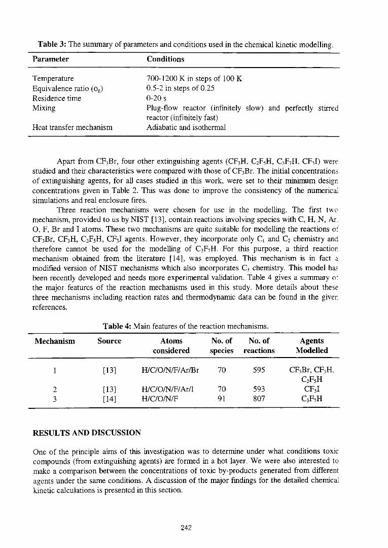
Table 3: The summary of parameters and conditions used in the chemical kinetic modelling.
Parameter Conditions
TemperatureEquivalence ratio (<j>g)Residence timeMixing
Heat transfer mechanism
700-1200 K in steps of 100 K0.5-2 in steps of 0.250-20 sPlug-flow reactor (infmitely slow) and perfectly stirredreactor (infinitely fast)Adiabatic and isothermal
Apart from CF3Br, four other extinguishing agents (CF3H, C2FsH, C3F7H, CF3I) werestudied and their characteristics were compared with those of CF3Br. The initial concentrationsof extinguishing agents, for all cases studied in this work, were set to their minimum designconcentrations given in Table 2. This was done to improve the consistency of the numericalsimulations and real enclosure fires.
Three reaction mechanisms were chosen for use in the modelling. The first twomechanism, provided to us by NIST [13], contain reactions involving species with C, H, N, Ar.0, F, Br and I atoms. These two mechanisms are quite suitable for modelling the reactions of
CF3Br, CF3H, C2FsH, CF3I agents. However, they incorporate only C\ and C2 chemistry andtherefore cannot be used for the modelling of C3F7H. For this purpose, a third reactionmechanism obtained from the literature [14], was employed. This mechanism is in fact :1
modified version of NIST mechanisms which also incorporates C3 chemistry. This model hasbeen recently developed and needs more experimental validation. Table 4 gives a summary 0:
the major features of the reaction mechanisms used in this study. More details about thesethree mechanisms including reaction rates and thermodynamic data can be found in the giver.references.
Table 4: Main features of the reaction mechanisms.
Mechanism Source Atoms No. of No. of Agentsconsidered species reactions Modelled
1 [13] HlCIOINIFIArIBr 70 595 CF3Br, CF3H,
C2FsH2 [13] HlCIOINIFIArll 70 593 CF3I
3 [14] HlCIOINIF 91 807 C3F7H
RESULTS AND DISCUSSION
One of the principle aims of this investigation was to determine under what conditions toxiccompounds (from extinguishing agents) are formed in a hot layer. We were also interested tomake a comparison between the concentrations of toxic by-products generated from differentagents under the same conditions. A discussion of the major fmdings for the detailed chemicalkinetic calculations is presented in this section.
242
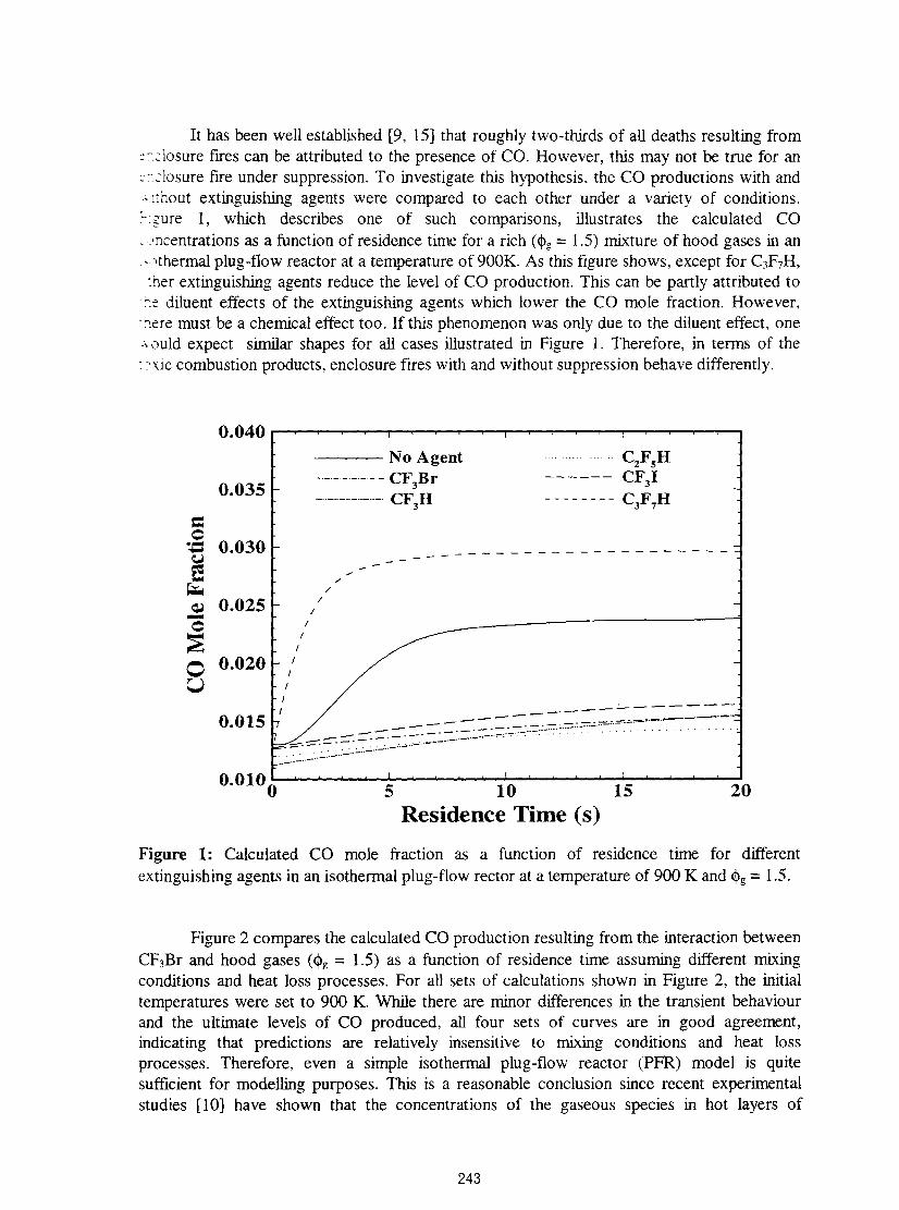
It has been well established [9, 15] that roughly two-thirds of all deaths resulting from:::-.closure fires can be attributed to the presence of CO. However, this may not be true for an~:-.:losure fire under suppression. To investigate this hypothesis, the CO productions with and.,nhout extinguishing agents were compared to each other under a variety of conditions.:=:gure 1, which describes one of such comparisons, illustrates the calculated CO,'ncentrations as a function ofresidence time for a rich (¢g = 1.5) mixture of hood gases in an·-othermal plug-flow reactor at a temperature of 900K. As this figure shows, except for C3F7H,
.her extinguishing agents reduce the level of CO production. This can be partly attributed to·:-.e diluent effects of the extinguishing agents which lower the CO mole fraction. However,·::ere must be a chemical effect too. If this phenomenon was only due to the diluent effect, one.;, ould expect similar shapes for all cases illustrated in Figure 1. Therefore, in terms of the: vxic combustion products, enclosure fires with and without suppression behave differently.
---- No Agent_._._._._._._- CF
3Br_..- .._.._.._.._. CF3H0.035
=Q~ 0.030e~~ 0.025-Q~o 0.020U
0.015
/
/
/
/
/
/I
/I
II
I
---===-. ::::-. :::-:. - --.--_.:_...:-:.~..-.
..- ..- ..-
C2FsH------ CF
31
- - - - - - - - C3F7H
---------------- - - --
-------------- - -. ~~. =-- - .- ._:::::.:.=::..:.::-=.:..="'•.=-~••_._--'-'"_...- -_.._.._-,- - -:-
5 10 15Residence Time (s)
20
Figure 1: Calculated CO mole fraction as a function of residence time for differentextinguishing agents in an isothermal plug-flow rector at a temperature of 900 K and ¢g= 1.5.
Figure 2 compares the calculated CO production resulting from the interaction betweenCF3Br and hood gases (¢g = 1.5) as a function of residence time assuming different mixingconditions and heat loss processes. For all sets of calculations shown in Figure 2, the initialtemperatures were set to 900 K. While there are minor differences in the transient behaviourand the ultimate levels of CO produced, all four sets of curves are in good agreement,indicating that predictions are relatively insensitive to mixing conditions and heat lossprocesses. Therefore, even a simple isothermal plug-flow reactor (PFR) model is quitesufficient for modelling purposes. This is a reasonable conclusion since recent experimentalstudies [10] have shown that the concentrations of the gaseous species in hot layers of
243

enclosure ftres are generally uniform especially for regions outside of the fire plume. On thebasis of the above conclusion, in the present work, PFR model was used as the main modellingtool.
=0.0250~~
ES~
Q,I 0.020-0~0U 0.015
---- Isothermal Plug-Flow Reactor- - - - - - - - Adiabatic Plug-Flow Reactor------ Isothermal Perfectly-Stirred Reactor-'-'-'-'--'-'- Adiabatic Perfectly-Stirred Reactor
5 10 15Residence Time (s)
20
Figure 2: CO mole fraction as a function of residence time for different mixing conditions ancheat transfer processes. For all calculations CF3Br was used as the extinguishing agent.
The concentrations of the major chemical species resulting from the decomposition 0:CF3Br in a hot layer (1200 K) are plotted in Figure 3 as a function of the global equivalenceratio. It can be seen that for both lean (<j>g < 1.0) and rich (<j>g ~ 1.0) hot layer mixtures, theconcentration of HF is much higher than those of other species and, hence, HF would be themajor threat in an enclosure fire under suppression. On the contrary, the effect of CF20 woulcbe negligible because, as Figure 3 illustrates, in typical enclosure ftres where 1.2 ~ <j>g ~ ::CF20 is almost non-existent. This may not be true for species like CO and HBr which theirconcentration become significant in the range of: 1.2~ <j>g ~ 2 (see Figure 3).
Effect of the temperature on the formation of HF is shown in Figure 4 where HF rno.efraction generated from the decomposition of CF3Br in a rich (<j>g =2) isothermal hot Iaye:mixture, is plotted as a function residence time at different reactor temperatures ranging fror700 K to 1200K. As Figure 4 shows, at low temperatures the production of HF is insigniftcar.:However, at temperatures above 1000 K, HF production is substantially higher. This can t:Y:explained in terms of the reaction rates which are functions of temperature. As a result, he'layer gases are unreactive for temperatures less than 700 K and become reactive k~
temperatures greater than 900 K. Typically for the lowest temperatures, very long residencetimes were required for complete reaction, while periods of less than 1 sec were quite sufficier:for complete reaction at high temperatures like 1200 K. Although Figure 4 only consider.CF3Br, results of this study (not shown here due to space limitation) indicate that t~.~
244

, : ~:~rature has, more or less, a similar effect on other extinguishing agent. This is quite... -.SlStent with the recent findings of other researchers [5-7].
2.5
HF
2.01.5<Pg
1.0
0.14
0.12
==0.10
0
=u 0.08e~~ 0.06-0~ 0.04
0.02~~ CO
Figure 3: Concentration of major species, in a hot layer (1200 K) after the application ofCF3Br, as a function of global equivalence ratio.
1100 K
800 K, 30 x HF
700 K, 100 x HF
20
1200 K
5 10 15Residence Time (s)
0.12
0.10
==0
= 0.08ue~~ 0.06-0~
0.04~
== 0.02
0.000
Figure 4: Mole fraction of HF as a function of residence time at different hot layertemperatures for CF3Br in a rich (<pg = 2) hot layer mixture.
245
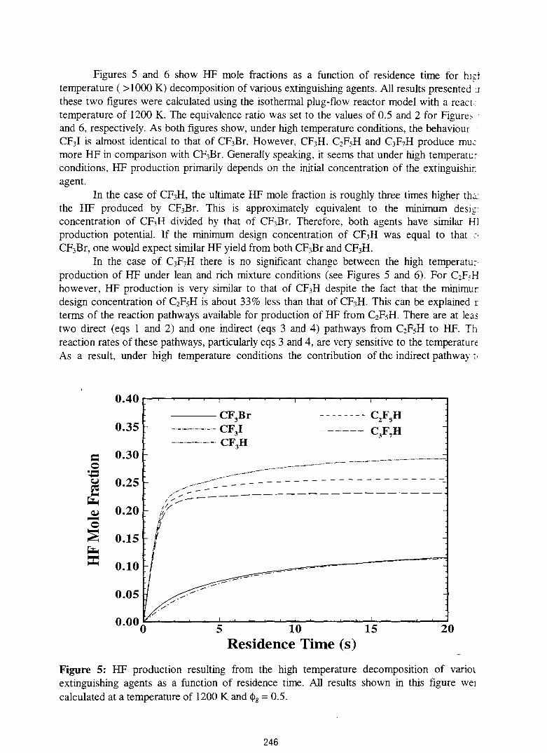
Figures 5 and 6 show HF mole fractions as a function of residence time for hi~l
temperature ( > 1000 K) decomposition of various extinguishing agents. All results presented :1
these two figures were calculated using the isothermal plug-flow reactor model with a react:temperature of 1200 K. The equivalence ratio was set to the values of 0.5 and 2 for Figures. .and 6, respectively. As both figures show, under high temperature conditions, the behaviourCF31 is almost identical to that of CF3Br. However, CF3H, C2FsH and C3F7H produce mucmore HF in comparison with CF3Br. Generally speaking, it seems that under high temperateconditions, HF production primarily depends on the initial concentration of the extinguishir.agent.
In the case of CF3H, the ultimate HF mole fraction is roughly three times higher tha:the HF produced by CF3Br. This is approximately equivalent to the minimum desig:concentration of CF3H divided by that of CF3Br. Therefore, both agents have similar HJproduction potential. If the minimum design concentration of CF3H was equal to that c'
CF3Br, one would expect similar HF yield from both CF3Br and CF3H.
In the case of C3F7H there is no significant change between the high ternperaturproduction of HF under lean and rich mixture conditions (see Figures 5 and 6). For C2F,Hhowever, HF production is very similar to that of CF3H despite the fact that the minimundesign concentration of C2FsH is about 33% less than that of CF3H. This can be explained n
terms of the reaction pathways available for production of HF from C2FsH. There are at leastwo direct (eqs 1 and 2) and one indirect (eqs 3 and 4) pathways from C2FsH to HF. Threaction rates of these pathways, particularly eqs 3 and 4, are very sensitive to the temperatureAs a result, under high temperature conditions the contribution of the indirect pathway t,
20
._..- .._.._..- ..- - - ._..- .._.._..-
-------- CFH2 5
------ C F H3 7
--------------------
5 10 15Residence Time (s)
-"--
----CF3Br-.-.-.-.-.-.-.- CF
31_.._.._.._.._..-. CF3H
/'--;':"-"-'------------------,/..... ---1/.,.,..,---
i'//1:
i;
II
0.000
0.05
0.40
0.35
=: 0.300~~ 0.25e~
~ 0.20-0~ 0.15~
== 0.10
Figure 5: HF production resulting from the high temperature decomposition of varioiextinguishing agents as a function of residence time. All results shown in this figure we]calculated at a temperature of 1200 K and <j>g =0.5.
246

0.40 f--
I
----CF3Br_._._.__._._.- CF31
-'-"--"-'- CF3H
- - - - - - - - C2F
sH
------ C F H3 7
20
-
-
-----------:.-------
5 10 15Residence Time (s)
___-_-=-.~ ==" .=r_-_-_.7=_,...,. _.-=-_~_':""""_-=-..-:;..= ::'._-=-:.-~_._.._._--_._. -
Ii'
0.30 - /jj
II
0.20 /iI _I -I /i /0.10 -! I /', /
11/
it'0.000
Figure 6: HF production resulting from the high temperature decomposition of variousextinguishing agents as a function of residence time. All results shown in this figure werecalculated at a temperature of 1200 K and <j>g =2.
(1)
(2)
(3)
(4)
the overall HF production becomes quite significant. Since the indirect pathway primarilyworks through the decomposition of C2FsH to CF3H, the total yield of HF from C2FsHbecomes very similar to that produced by CF3H. However, for low temperature conditions( ~ 1000 K), the role of the indirect pathway becomes insignificant and consequently HFformation is dramatically decreased (see Figure 7).
Despite all differences, the set of results plotted in Figures 5 and 6 represents a similartrend leading to the following statement: regardless of the equivalence ratio, the halonalternative agents considered in this study can be ranked as CF3H > C2FsH > C3F7H > CF3I interms of their potential for HF generation under high temperature conditions (1100-1300 K)associated with typical enclosure fires, (see Figure 8 as an example). It should be noted that,exactly the same ranking exists for agents minimum design concentration (see Table 2 ).Therefore, the above statement is of great practical importance since it highlights the relationbetween the minimum design concentration of the agent and its potential to form toxic byproducts.
?4.7

20
-------
.-.._..--._.--
------
15
.------
...,.. ......
- - - - - - - - ClFsH
------ C3F7H
---
5 10Residence Time (s)
-----
----CF3Br
_. __._._._._- CF31
_._._.._.._..- CF3H
0.15
0.10
0.05
Figure 7: HF production resulting from the low temperature decomposition of variouextinguishing agents as a function of residence time. All results shown in this figure werecalculated at a temperature of 1000 K and </>g =2.
2.52.01.5<l>g
1.0
0.35
0.30 CF3H
c::ClFsH
0 0.25~~
ES 0.20~~-0 0.15 C3F7H
~~
0.10== CF3Br
CF310.05
Figure 8: HF production of various extinguishing agents as a function of </>g. All results showrin this figure were calculated at a temperature of 1100 K and 20 s residence time.
248

CO:\TCLUSIONS
=~tailed chemical kinetic modelling techniques were employed to predict the formation of. -xic by-products from the decomposition of halon alternative agents in enclosure fires under-uppression. The calculated results for a variety of new extinguishing agents were used to<'Jdy the conditions under which the toxic by-products are formed. The behaviour of new~~ents in suppressed fires, has also compared with those of CF3Br. This study leads to the. ·lIowing conclusions:
the formation of major toxic by-products is kinetically controlled;
all agents, but C3F7H, tend to suppress the production of CO in hot layer;
hydrogen fluoride (HF) constitutes the bulk of toxic by-product in enclosure fires undersuppression;
- in a typical hot ceiling layer, the decomposition of extinguishing agents occurs attemperatures greater than 1100 K;
for new halon alternatives, the concentration of toxic by-products (particularly HF)generated from the interaction between hot ceiling layers and extinguishing agents, isprimarily a function of minimum design concentration;
6. on the basis of HF production potential, the extinguishing agents studied in this work canbe ranked in the following order: CF3H > C2FsH > C3F7H > CF3I.
ACKNOWLEDGMENTS
This work was funded by the Australian Research Council, North American FireGuardian Technology Australia Pty Ltd and Wormald Australia Pty Limited through theARC-Collaborative Grant scheme.
REFERENCES
[1] Dinenno, Pl, The SFPE handbook of Fire Protection Engineering, Second Edition,Section 4, Chapter 7, pp. 145-166, 1995.
[2] Sheinson, RS, Penner-Hahn, JE, and Indritz, D, Fire Safety Journal, 15, p 437, 1989.
[3] Ferreira, Ml, Hanauska, CP, and Pike, MT, Halon Alternative Technical WorkingConference, Albuquerque, NM, 1992.
[4] Sheinson, RS, Musick, lK, and Carhart, HW, Journal of Fire and Flammability,12,pp 229-235, 1981.
249

[5] Linteris, GT, King, MD, Liu, A, Womeldrof, C, and Hsin, YE, Halon Options TechnicalWorking Conference, Albuquerque, NM, 1994.
[6] Linteris, GT, and Truett, L, Combustion Institute/Eastern State Section Meeting.Clearwater beach, FL, 1994.
[7] Babushok, V, Burgess, DFR, Linteris, G and Tsang, W, Halon Options Technical WorkingConference, Albuquerque, NM, 1995.
[8] Kee, RJ, Miller, JA, and Jefferson, TH, Sandia National Laboratories, SAND 80-8003.1989.
[9] Pitts, WM, Progress in Energy and Combustion Science, 21, pp 197-237, 1995.
[10] Morehart, JH, PhD Thesis, California Institute of Technology, USA, 1990.
[11] Lutz, AE, Kee, RJ, and Miller, JA, Sandia National Laboratories, SAND 87-8248, 1988.
[12] Glarborg, P, Kee, RJ, Grear, JF, and Miller, JA, Sandia National Laboratories, SAND 868209, 1986.
[13] Burgess, DRF, Zachariah, MR, Tsang, W, and Westmorland, PR, National Institute ofStandards and Technology, USA, Technical Note NIST 1412, 1995.
[14] Hynes, RG, Mackie, JC, Masri, AR, Combustion and Flame, Submitted, 1997.
[15] Pitts, WM, Fire Safety Journal, 23, pp 271-303, 1994.
250