application of a two-dimensional model to simulate flow and
TRANSCRIPT

Application of a two-dimensional model to simulate¯ow and transport in a macroporous agricultural soilwith tile drains
K . C . A B B A S P O U Ra , A . K O H L E R
b , J . S I M U N E Kc , M . F R I T S C H
b & R . S C H U L I Nd
aSwiss Federal Institute for Environmental Science and Technology (EAWAG), 8600 DuÈbendorf, Switzerland, bSwiss Federal Institute
of Technology, Department for Land and Water Management ETH HoÈnggerberg, 8093 ZuÈrich, Switzerland, cGeorge E. Brown Jr.
Salinity Laboratory, US Department of Agriculture, ARS, 450 West Big Spring Road, Riverside, CA 92507, USA, and dSwiss Federal
Institute of Technology, Department of Soil Protection, Grabenstrasse 3, 8952 Schlieren, Switzerland
Summary
It is essential that important ®eld processes are taken into account to model water ¯ow and chemical
transport accurately in agricultural ®elds. Recent ®eld studies indicate that transport through macropores
can play a major role in the export of solutes and particulates from drained agricultural land into surface
water. Non-ideal drain behaviour may further modify the ¯ow and transport. We extended an existing
two-dimensional ¯ow and transport model for variably saturated soils (SWMS_2D) by adding a
macropore domain and an additional Hooghoudt drain boundary condition. The Hooghoudt boundary
condition accounts for an entrance head needed to initiate ¯ow into the drains. This paper presents the
application of the new model (M-2D) to an agricultural ®eld in Switzerland. To understand interactions
between macropore ¯ow and drains better we simulated water ¯ow and bromide transport for four
different ®eld scenarios. We considered both collector drains only with an ideal drain boundary condition
(with and without macropores) and collectors and laterals with a Hooghoudt boundary condition (also
with and without macropores). For each scenario, inverse modelling was used to identify model
parameters using 150 days of data on observed cumulative discharge, water table depth, and tracer
concentration. The models were subsequently tested against a 390-day validation data set. We found that
the two additional components (macropore ¯ow, drain entrance head) of the M-2D model were essential
to describe adequately the ¯ow regime and the tracer transport data in the ®eld.
Introduction
Leaching of nitrogen applied as fertilizer on agricultural land
continues to be a major cause of soil and water pollution.
Miller (1975) showed that yearly losses of nitrogen from tile
drains could be as large as 59 kg ha±1 year±1 in Ontario,
Canada, and Baker et al. (1975) reported annual NO3±-N losses
as large as 93 kg ha±1 year±1 from a tile-drained cropland in
Iowa, USA. Braun et al. (1993) found that 61% of the total
nitrogen load in the surface waters in Switzerland came from
agricultural land. The Swiss Federal Of®ce of Environment,
Forest and Landscape (FOEFL, 1997) estimated an annual
nitrogen input of 15±50 kg ha±1 year±1 into the river Rhine
from agricultural land. Drained lands are frequently identi®ed
as being major sources of surface water pollution due to the
leaching of nitrate (Evans et al., 1989).
We measured nitrate concentrations of the ef¯uent of a
drainage system for more than a year with many discharge
events induced by rain. Increases in nitrate concentration were
found to be proportional to increases in the drain discharge.
When the drain discharge ceased, nitrate concentrations
decreased to their background concentration. Such behaviour
is typical for preferential transport processes. Everts & Kanwar
(1990) also arrived at this conclusion based on somewhat
similar tile drainage studies. The positive correlation between
nitrate concentrations and drain discharge will signi®cantly
increase the amount of leached nitrate.
Relevant transport mechanisms cannot be deduced from
only the measured nitrate signal in a drain ef¯uent (break-
through curve), since the soil is then treated as a black box.
Detailed knowledge of the performance of the drainage
system, of the soil system itself, and of preferential ¯ow
processes within the unsaturated soil appears necessary in
order to assess and uniquely describe the coupled soil±drain
system fully. Indeed, the importance of macropore ¯ow toCorrespondence: K. C. Abbaspour. E-mail: [email protected]
Received 15 May 2000; revised version accepted 8 January 2001
European Journal of Soil Science, September 2001, 52, 433±447
# 2001 Blackwell Science Ltd 433

transport of nitrogen (Larsson & Jarvis, 1999), pesticide
leaching (Harris et al., 1994), and colloidal particles (Jarvis
et al., 1999) has been well documented, and several models
now account for one-dimensional transport through macro-
pores, such as Macro (Jarvis, 1994), PLM (Nicholls & Hall,
1995), and Transmit (Hutson & Wagenet, 1995).
Mohanty et al. (1998) comprehensively studied the
preferential transport of nitrate to a tile drain in an intermittent
¯ood-irrigated ®eld in New Mexico. They concluded that
preferential ¯ow intercepted by a tile drain was generated in
close proximity of the drain and was essentially oriented
vertically. Lennartz et al. (1999), through ®eld experiments
with KBr in an experimental ®eld near Kiel, Germany,
concluded that preferential solute movement characterized by
the early arrival of Br± at the drain outlet was observed in all
three years of the experiment, suggesting the existence of a
fast-transporting ¯ow domain as an intrinsic soil property at
the tile-drained site. What is less clear, however, is the
complication that may arise from non-ideal drain behaviour.
Our ®eld observations suggest that non-ideal drainage may
modify the role of preferential ¯ow in short-circuiting solute
transport to drains. This modi®cation arises from a positive
head that seems to be necessary for inducing ¯ow through the
drains.
To enhance our understanding of the relevant ¯ow and
transport processes, for a coupled soil±drain system, we
modi®ed an existing program (SWMS_2D of Simunek et al.,
1994) by implementing two additional features describing a
macropore domain and a new boundary condition, referred to
as the Hooghoudt boundary condition (Kohler et al., 2001a).
Theoretical aspects of the new M-2D model are described in
detail in Kohler et al. (2001b). In this paper we present a
modelling approach in which the relevant ¯ow and transport
mechanisms are investigated using simulations of a tracer
experiment in the ®eld. The main objectives are application of
M-2D to data collected from the experiment, simulation of
different drainage scenarios, and exploration of the importance
of various ¯ow and transport mechanisms in a soil±drain
system. We used a bromide tracer as a precursor for
understanding nitrate transport.
Theory
General description of M-2D
We provide here only a brief summary of various features of
M-2D and refer interested readers to Kohler et al. (2001b) for a
more detailed description. Figure 1 illustrates the two micro-
and macropore domains of the M-2D model. The micropore
domain (hereinafter referred to as the micro-domain) repre-
sents the soil matrix where water ¯ow is governed by the
Richards equation and solute transport by the Fickian-based
convection±dispersion equation according to (Simunek et al.,
1994)
@�
@t� @
@xi
K�h� KAij
@h
@xj
� KAij
� �� �ÿ S �1�
for the ¯ow, and
@�c
@t� @
@xi
�Dij@c
@xi
� �ÿ @qic
@xi
�
�w�c� �ss�� w�� s�ÿ Scs �2�
for the transport. In the above equations � is the volumetric
water content, h is the pressure head, S is a sink term, xj
Figure 1 Illustration of the two ¯ow
domains used in the extended M-2D model.
434 K. C. Abbaspour et al.
# 2001 Blackwell Science Ltd, European Journal of Soil Science, 52, 433±447

(j = 1,2) are the spatial coordinates, t is time, KAij are
components of a dimensionless anisotropy tensor KA, and
K(h) is the unsaturated hydraulic conductivity function, c is the
solution concentration, s is the sorbed concentration, qi is the
ith component of the volumetric ¯ux, �w and �s are ®rst-order
rate constants for solutes in the liquid and solid phases,
respectively, w and s are zero-order rate constants for the
liquid and solid phases, respectively, � is the soil bulk density,
cs is the concentration of the sink term, and Dij is the
dispersion coef®cient tensor.
The macropore domain (macro-domain) in Figure 1
represents surface-connected cracks and macropores, in which
water ¯ow is one-dimensional, non-capillary, and laminar, and
where solute transport is purely convective.
As depicted in Figure 1, the macro-domain has the same
geometry as the micro-domain. An individual macropore is
assumed to consist of a sequence of macropore nodes (macro-
nodes) that extend vertically from a surface micropore node
(micro-node) down to a desired depth. Each macro-node
coincides with a certain micro-node, but not vice versa (i.e. not
all micropores are close to or connected with a macropore).
The width of a macro-node is assumed to be equal to the width
of a corresponding micro-node at the soil surface.
Following Gerke & van Genuchten (1993), water exchange
between a micro-node and a corresponding macro-node is
calculated as a function of the pressure head difference
between the two nodes. We assume that the macro-node has a
pressure head equal to the height of the water column in the
macropore above that node. Surface macropore nodes can also
store surface water (simulating ponding condition). If the
micro-domain cannot absorb all applied water at the surface
then excess water is directed to the surface macro-nodes from
where it enters a macropore and may in®ltrate laterally into the
micro-domain.
Within the soil pro®le we have the same mechanism of
exchanging ¯ow as for the surface nodes. If the pressure head
at a certain micro-node reaches a critical value close to
saturation (speci®ed by the parameter hc), and a corresponding
macro-node exists and is not yet saturated, then water will ¯ow
from the micro-node to the macro-node according to the
interaction term expressed as
Qe;i � ÿKi�hmic� dhi
L2c
; �3�
in which
dhi = hmic,i ± hmac,i, (4)
where Qe is the exchange ¯ow, Ki(hmic) is the hydraulic
conductivity of micro-node i, and Lc is the characteristic length
representing the average spacing of the macropores as well as
the geometry of the macroporous system. Gerke & van
Genuchten (1993) used a similar equation in their model and
derived the following expression for the characteristic length:
L2c �
a2�
�; �5�
where � is a geometric factor (equal to 3 for rectangular slabs
and 15 for spherical shapes), a is the distance between the
centre of the soil aggregates or soil matrix domain and the
centre of the macropores, and � is an empirical factor set equal
to 0.4.
The numerical procedure invoked for successive calculation
of ¯ow and transport between the micro- and macro-domains
is depicted in Figure 2. On the assumption that the micro-
domain was just solved at time Tk, the model calculates ¯ow
and transport in the macro-domain as follows. During step 1,
pressure heads of the micro-domain at time Tk are compared
with those of the macro-domain at time Tk±1, and the
interaction term for ¯ow between the two ¯ow domains is
calculated. Next, water and solute is distributed in each
macropore. During step 2, ¯ow and transport in the micro-
domain are solved for the time step Tk+1 using as boundary
conditions the macropore interaction terms Qe and Ce
calculated at Tk. Kohler et al. (2001b) provide more details
of the coupling between macro- and micro-domains in M-2D.
One popular way to model a drain in a ®nite element model
at the ®eld scale is to represent the drain as a node with a
boundary condition that depends on the system. The pressure
head is then set to zero when the drain node is saturated,
whereas the ¯ux is set to zero when the drain node is
unsaturated. To account for the drain resistance some
programs adjust the conductivity around the drain node. This
approach, however, cannot account for non-ideal behaviour as
expressed by the occurrence of an entrance head around the
drain (i.e. a drain entrance resistance). By contrast, the
Hooghoudt drain boundary condition implemented in the M-
2D code corresponds to a Neumann boundary condition, with
tile drainage ¯ow being dependent upon the head at a reference
node (i.e. midway between two drains). The ¯ux according to
the Hooghoudt formulation is calculated using
Figure 2 Steps in the numerical procedure used to solve the water
¯ow and solute transport equations. In step 1, the macropore ¯ow
and the interaction between the two ¯ow regions are calculated. In
step 2, the calculated macropore ¯ow is used as a boundary
condition during the next time step for the micro-domain.
Flow and transport in a macroporous soil 435
# 2001 Blackwell Science Ltd, European Journal of Soil Science, 52, 433±447
qD � A�hT ÿ he� � B�h2T ÿ h2
e�; �6�
where qD is the drain discharge [LT±1] representing the
prescribed out¯ow at the drain node, A and B are ®tting
parameters, hT is the elevation of the groundwater table
midway between the drains relative to the drain level [L], and
he is given by the empirical relationship he = ChT + he0, in
which C is an empirical constant and he0 the entrance head (i.e.
the elevation of the groundwater table above the drain level
before the onset of ¯ow). Note that the above empirical
relations can easily be replaced by another locally calibrated
model relating drain discharge to the water table height
measured at a convenient location.
Materials and methods
The experimental site was in a 40-km2 catchment in the
plain of the Furtbach valley, northwest of ZuÈrich,
Switzerland. Drained mollic soils in this valley are under
intensive agriculture. Pertinent information describing the
chemical and physical state of the soil pro®le used in the
modelling study is summarized in Table 1. The drainage
system consists of laterals (old clay tubes) with a spacing
of 20 m at a depth of 1 m, and collector drains (new
polyethylene tubes) with a spacing of 90 m at a depth of
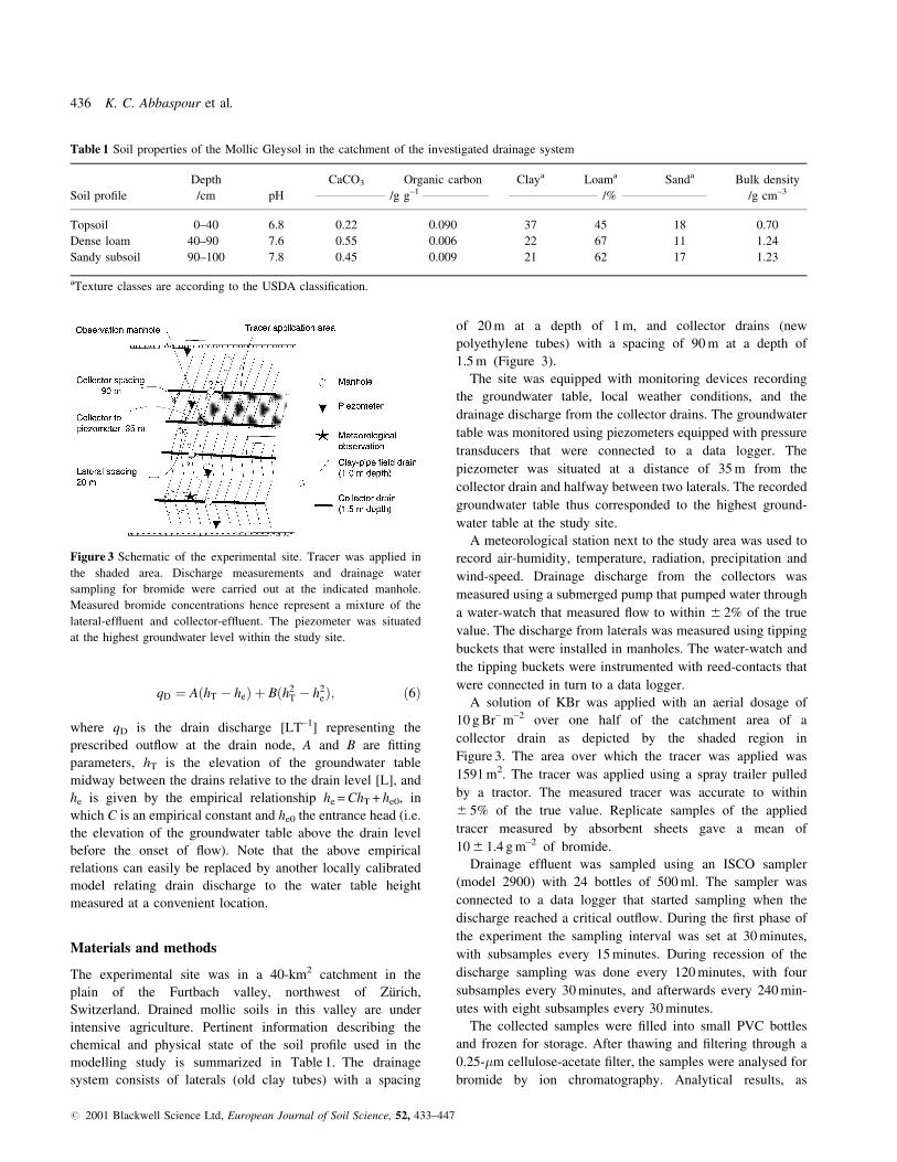
1.5 m (Figure 3).
The site was equipped with monitoring devices recording
the groundwater table, local weather conditions, and the
drainage discharge from the collector drains. The groundwater
table was monitored using piezometers equipped with pressure
transducers that were connected to a data logger. The
piezometer was situated at a distance of 35 m from the
collector drain and halfway between two laterals. The recorded
groundwater table thus corresponded to the highest ground-
water table at the study site.
A meteorological station next to the study area was used to
record air-humidity, temperature, radiation, precipitation and
wind-speed. Drainage discharge from the collectors was
measured using a submerged pump that pumped water through
a water-watch that measured ¯ow to within 6 2% of the true
value. The discharge from laterals was measured using tipping
buckets that were installed in manholes. The water-watch and
the tipping buckets were instrumented with reed-contacts that
were connected in turn to a data logger.
A solution of KBr was applied with an aerial dosage of
10 g Br± m±2 over one half of the catchment area of a
collector drain as depicted by the shaded region in
Figure 3. The area over which the tracer was applied was
1591 m2. The tracer was applied using a spray trailer pulled
by a tractor. The measured tracer was accurate to within
6 5% of the true value. Replicate samples of the applied
tracer measured by absorbent sheets gave a mean of
10 6 1.4 g m±2 of bromide.
Drainage ef¯uent was sampled using an ISCO sampler
(model 2900) with 24 bottles of 500 ml. The sampler was
connected to a data logger that started sampling when the
discharge reached a critical out¯ow. During the ®rst phase of
the experiment the sampling interval was set at 30 minutes,
with subsamples every 15 minutes. During recession of the
discharge sampling was done every 120 minutes, with four
subsamples every 30 minutes, and afterwards every 240 min-
utes with eight subsamples every 30 minutes.
The collected samples were ®lled into small PVC bottles
and frozen for storage. After thawing and ®ltering through a
0.25-�m cellulose-acetate ®lter, the samples were analysed for
bromide by ion chromatography. Analytical results, as
Table 1 Soil properties of the Mollic Gleysol in the catchment of the investigated drainage system
Depth CaCO3 Organic carbon Claya Loama Sanda Bulk density
Soil pro®le /cm pH ___________________ /g g±1 __________________ ________________________ /% _______________________ /g cm±3
Topsoil 0±40 6.8 0.22 0.090 37 45 18 0.70
Dense loam 40±90 7.6 0.55 0.006 22 67 11 1.24
Sandy subsoil 90±100 7.8 0.45 0.009 21 62 17 1.23
aTexture classes are according to the USDA classi®cation.
Figure 3 Schematic of the experimental site. Tracer was applied in
the shaded area. Discharge measurements and drainage water
sampling for bromide were carried out at the indicated manhole.
Measured bromide concentrations hence represent a mixture of the
lateral-ef¯uent and collector-ef¯uent. The piezometer was situated
at the highest groundwater level within the study site.
436 K. C. Abbaspour et al.
# 2001 Blackwell Science Ltd, European Journal of Soil Science, 52, 433±447

measured by duplicate sampling, had an average standard
deviation of 0.12 p.p.m., equivalent to a coef®cient of variation
of 9%.
On the day of the tracer application (23 August 1995)
sun¯owers grown on the site were about 5 cm high. The
sun¯owers were sampled for bromide on 10 October 1995
by collecting cuttings from 14 subareas of 0.16 m2 each. In
1996 the site was cropped with sugar beets, which were
sampled on 4 September 1996. Three plants were harvested
in each subarea, and their leaves and branches were
wrapped separately. The plants were then chopped and
oven-dried at 60°C for 24 h. All samples were weighed,
and a subsample was milled for subsequent analysis. From
each sample, 1.0 g of the dried and milled plant material
was extracted for 30 minutes with 48 ml of water and 2 ml
of 12.5% trichloracetic acid and measured in a 10-fold
dilution with chromatography.
Calculations
Evapotranspiration
Potential evapotranspiration Ep was calculated from recorded
weather data according to the model of Allen et al. (1994).
Actual evapotranspiration Ea was calculated by multiplying
the potential evapotranspiration by a time-dependent crop
factor, c(t), and a soil pressure head-dependent reduction
factor, a(h):
Ea = c(t) a(h) Ep. (7)
The relation c(t) was taken from DVWK (1996) as illustrated
in Figure 4(a) for the two crops (sun¯owers in autumn 1995
and sugar beet during 1996). For a(h) we used a stress function
given by Feddes et al. (1978), modi®ed to account for
evaporation when transpiration is negligible due to water-
logging conditions (Figure 4b).
Unsaturated soil hydraulic properties
The soil hydraulic properties were described according to the
van Genuchten model (van Genuchten, 1980) for the water
retention function:
Se�h� � ��h� ÿ �r
�s ÿ �r
� 1
1� j�hjn� �m h < 0 �8�
�(h) = �s h > 0 (9)
and the van Genuchten±Mualem model (Mualem, 1976) for
the hydraulic conductivity function:
KsS0:5e 1ÿ 1ÿ S1=m
e
� �mh i2
h < 0
Ks h � 0;
where � and n are the van Genuchten parameters, Se is the
effective water saturation, m = 1 ± 1/n, �r and �s are the residual
and saturated water contents, respectively, and Ks is the
saturated hydraulic conductivity.
The hydraulic conductivity for the macropore domain was
calculated as a function of the actual saturation of the macro-
node according to
Ks;mac
�mac
e
� �n�
0 < �mac < �s;mac
Ks;mac �mac � �s;mac
0 �mac � 0;
where Ks,mac is the saturated hydraulic conductivity of the
macropore, �mac is the water content of the macropore, �s,mac is
the saturated water content of the macropore, e is the soil
macroporosity, i.e. the total volume of macropores per bulk
soil volume, and n* is an empirical exponent accounting for
the pore size distribution.
Initial and boundary conditions
The initial pressure head condition for the experiments was as
follows:
h(x,z,t) = h0(x,z) t = 0, (12)
where h0 is the prescribed pressure head. Pressure heads were
assumed to be in hydrostatic equilibrium with the groundwater
table being at a depth of 1.1 m to a depth of 0.3 m below the
soil surface. At the soil surface the pressure head was speci®ed
to be ±3 m due to evaporation; hence, the initial pressure head
was assumed to decrease linearly from ±0.8 m at 0.3 m depth to
±3 m at the soil surface.
The potential ¯uid ¯ux across the soil±air interface at the
soil surface was controlled by prevailing atmospheric
Figure 4 Graphs of (a) the crop factor function c(t) for the
sun¯ower and sugar beet as described by DVWK (1996), and (b)
the response function to water stress a(h) as used in this study.
K�h� � { �10�
Kmac��mac� � { �11�
Flow and transport in a macroporous soil 437
# 2001 Blackwell Science Ltd, European Journal of Soil Science, 52, 433±447
conditions. The actual ¯ux, however, can be reduced by
soil moisture conditions near the surface. The boundary
condition at the surface of the soil may change from a
prescribed head to a prescribed ¯ux type condition, and
back again to a prescribed head. The absolute ¯ux value is
obtained using the following two limiting conditions
(Simunek et al., 1994):
K�h��@h
@z� 1
�� E �13�
and
hmin � h � hmax; �14�where E is the potential rate of in®ltration (rain or
irrigation) or evaporation under the prevailing atmospheric
condition, h is the pressure head at the soil surface, and
hmin and hmax are, respectively, the minimum and the
maximum pressure heads allowed at the soil surface. In
SWMS_2D, hmax is set equal to zero since no ponding is
allowed. In M-2D the excess water that cannot in®ltrate
into the soil matrix is directed to surface macropores. The
value of hmin is determined from the equilibrium conditions
between soil water and atmospheric water vapour. In our
example hmin was set equal to ±10 000 m.
The lower boundary was represented by the drainage system
consisting of collector and laterals. For collector drains we
assumed an ideal drain boundary condition, while laterals were
represented using the Hooghoudt boundary condition as
described earlier. The parameters A, B, C, and he0 in the
Hooghoudt boundary, Equation (6), were calibrated against the
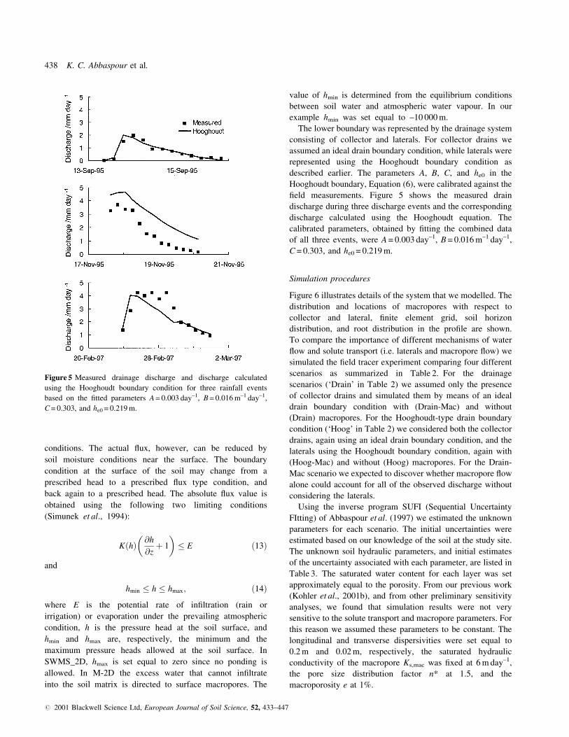
®eld measurements. Figure 5 shows the measured drain
discharge during three discharge events and the corresponding
discharge calculated using the Hooghoudt equation. The
calibrated parameters, obtained by ®tting the combined data
of all three events, were A = 0.003 day±1, B = 0.016 m±1 day±1,
C = 0.303, and he0 = 0.219 m.
Simulation procedures
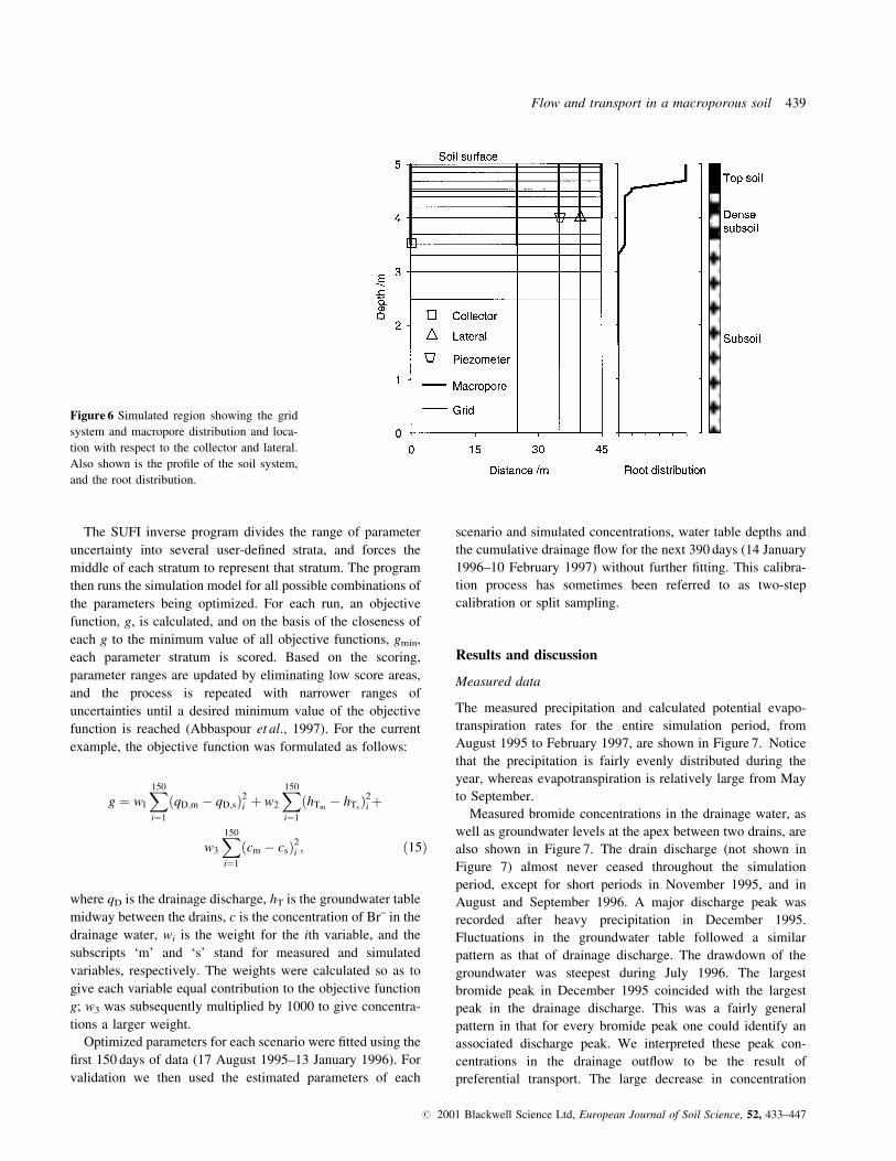
Figure 6 illustrates details of the system that we modelled. The
distribution and locations of macropores with respect to
collector and lateral, ®nite element grid, soil horizon
distribution, and root distribution in the pro®le are shown.
To compare the importance of different mechanisms of water
¯ow and solute transport (i.e. laterals and macropore ¯ow) we
simulated the ®eld tracer experiment comparing four different
scenarios as summarized in Table 2. For the drainage
scenarios (`Drain' in Table 2) we assumed only the presence
of collector drains and simulated them by means of an ideal
drain boundary condition with (Drain-Mac) and without
(Drain) macropores. For the Hooghoudt-type drain boundary
condition (`Hoog' in Table 2) we considered both the collector
drains, again using an ideal drain boundary condition, and the
laterals using the Hooghoudt boundary condition, again with
(Hoog-Mac) and without (Hoog) macropores. For the Drain-
Mac scenario we expected to discover whether macropore ¯ow
alone could account for all of the observed discharge without
considering the laterals.
Using the inverse program SUFI (Sequential Uncertainty
FItting) of Abbaspour et al. (1997) we estimated the unknown
parameters for each scenario. The initial uncertainties were
estimated based on our knowledge of the soil at the study site.
The unknown soil hydraulic parameters, and initial estimates
of the uncertainty associated with each parameter, are listed in
Table 3. The saturated water content for each layer was set
approximately equal to the porosity. From our previous work
(Kohler et al., 2001b), and from other preliminary sensitivity
analyses, we found that simulation results were not very
sensitive to the solute transport and macropore parameters. For
this reason we assumed these parameters to be constant. The
longitudinal and transverse dispersivities were set equal to
0.2 m and 0.02 m, respectively, the saturated hydraulic
conductivity of the macropore Ks,mac was ®xed at 6 m day±1,
the pore size distribution factor n* at 1.5, and the
macroporosity e at 1%.
Figure 5 Measured drainage discharge and discharge calculated
using the Hooghoudt boundary condition for three rainfall events
based on the ®tted parameters A = 0.003 day±1, B = 0.016 m±1 day±1,
C = 0.303, and he0 = 0.219 m.
438 K. C. Abbaspour et al.
# 2001 Blackwell Science Ltd, European Journal of Soil Science, 52, 433±447
The SUFI inverse program divides the range of parameter
uncertainty into several user-de®ned strata, and forces the
middle of each stratum to represent that stratum. The program
then runs the simulation model for all possible combinations of
the parameters being optimized. For each run, an objective
function, g, is calculated, and on the basis of the closeness of
each g to the minimum value of all objective functions, gmin,
each parameter stratum is scored. Based on the scoring,
parameter ranges are updated by eliminating low score areas,
and the process is repeated with narrower ranges of
uncertainties until a desired minimum value of the objective
function is reached (Abbaspour et al., 1997). For the current
example, the objective function was formulated as follows:
g � wl
X150
i�1
�qD;m ÿ qD;s�2i � w2
X150
i�1
�hTmÿ hTs
�2i�
w3
X150
i�1
�cm ÿ cs�2i ; �15�
where qD is the drainage discharge, hT is the groundwater table
midway between the drains, c is the concentration of Br± in the
drainage water, wi is the weight for the ith variable, and the
subscripts `m' and `s' stand for measured and simulated
variables, respectively. The weights were calculated so as to
give each variable equal contribution to the objective function
g; w3 was subsequently multiplied by 1000 to give concentra-
tions a larger weight.
Optimized parameters for each scenario were ®tted using the
®rst 150 days of data (17 August 1995±13 January 1996). For
validation we then used the estimated parameters of each
scenario and simulated concentrations, water table depths and
the cumulative drainage ¯ow for the next 390 days (14 January
1996±10 February 1997) without further ®tting. This calibra-
tion process has sometimes been referred to as two-step
calibration or split sampling.
Results and discussion
Measured data
The measured precipitation and calculated potential evapo-
transpiration rates for the entire simulation period, from
August 1995 to February 1997, are shown in Figure 7. Notice
that the precipitation is fairly evenly distributed during the
year, whereas evapotranspiration is relatively large from May
to September.
Measured bromide concentrations in the drainage water, as
well as groundwater levels at the apex between two drains, are
also shown in Figure 7. The drain discharge (not shown in
Figure 7) almost never ceased throughout the simulation
period, except for short periods in November 1995, and in
August and September 1996. A major discharge peak was
recorded after heavy precipitation in December 1995.
Fluctuations in the groundwater table followed a similar
pattern as that of drainage discharge. The drawdown of the
groundwater was steepest during July 1996. The largest
bromide peak in December 1995 coincided with the largest
peak in the drainage discharge. This was a fairly general
pattern in that for every bromide peak one could identify an
associated discharge peak. We interpreted these peak con-
centrations in the drainage out¯ow to be the result of
preferential transport. The large decrease in concentration
Figure 6 Simulated region showing the grid
system and macropore distribution and loca-
tion with respect to the collector and lateral.
Also shown is the pro®le of the soil system,
and the root distribution.
Flow and transport in a macroporous soil 439
# 2001 Blackwell Science Ltd, European Journal of Soil Science, 52, 433±447
from July to October of 1996 was most likely caused by water
uptake by plants. Bromide uptake by sun¯owers as measured
in October 1995 was 1.32 g m±2, which is about 13% of the
applied amount. In the following year, sugar beets took up
5.08 g m±2, which is about 50% of the applied amount. The
bromide accumulated mostly in the leaves.
A mass balance for bromide is provided in Table 4. For the
®rst measurement on 10 October 1995 there was an error of
±38% in the mass balance attributed largely to the uncertainty
associated with the spatial distribution of Br± in the soil and
plants. This uncertainty is indicated by the large coef®cient of
variation of the measurements indicated in Table 7. The
second measurement taken on 4 September 1996, although
much more accurate at +2% error, still suffers from the same
degree of uncertainty as the previous case. Other authors have
also reported large Br± uptakes for different crops. For
example, Owens et al. (1985) measured an uptake of 32%
for grass, Kung (1990) measured 53% uptake by potatoes, and
Steenhuis et al. (1990) reported a 30% uptake of Br± by corn.
A more detailed analysis of the bromide balance in this study
can be found in Kohler (2001).
Comparison of model simulations with ®eld measurements
Figures 8±11 compare measured and simulated bromide
concentration in drainage water, cumulative drain discharges,
and groundwater apex height for the periods of calibration (17
August 1995±13 January 1996) and validation (14 January
1996±10 February 1997) for the four scenarios Drain, Drain-
Mac, Hoog, and Hoog-Mac (Table 2), respectively. In Table 5
we report, for the calibration and validation periods, the root
mean square error (RMSE) and the coef®cient of determina-
tion (R2) for the four scenarios. For reasons to be discussed
later, we also report for the Hoog-Mac scenario RMSE and R2
values for bromide concentrations for a partial validation
period of January 1996 to July 1996, i.e. the period after which
bromide concentrations decreased signi®cantly due to uptake
by the sugar beet.
Parameters obtained for the calibration period using the
inverse procedure are summarized in Table 6. Note that some
of the estimated parameters in Table 6 are outside the range of
the initial estimates in Table 3. During the optimization after
each iteration, the program SUFI allows initial parameter
ranges to be modi®ed, hence making the initial guesses not
very critical.
It has been our experience (Abbaspour et al., 2000; Schmied
et al., 2000) that without accounting for all relevant ¯ow and
transport processes, inverse optimization often produces
physically unrealistic parameters. Optimized parameters are
in such cases forced to account for processes that are neglected
in the model. For example, if macropore ¯ow, present in the
®eld, is not accounted for in calculations, an inverse model that
uses discharge in the objective function will overestimate the
saturated hydraulic conductivity to account for discharge peaks
through the macropores. Although in this case discharge may
be satisfactorily replicated using the inversely obtained
parameters, observed water table heights and concentrations
in the discharge water will, however, be poorly described.
Notice from Table 6 that for the current example the saturated
hydraulic conductivity of all three layers is signi®cantly
overestimated for both scenarios (Drain and Hoog) that ignore
macropore ¯ow.
Simulation results for the Drain scenario are shown in
Figure 8. This scenario is equivalent to running the original
SWMS_2D code of Simunek et al. (1994) without the
macropore domain or the Hooghoudt drain boundary
condition. It is evident that the concentration peaks are
not simulated well at all. As expected, simulated concen-
trations show stepwise increases in the collector drain, with
a maximum in the summer of 1996, followed by gradual
Table 2 Description of four scenarios used to compare the signi®cance of different ¯ow and transport mechanisms for the bromide tracer
experiment
Simulation scenario Comments
Drain Model includes only an ideal drain boundary condition representing collector drains. No laterals or macropores are
considered. This scenario is equivalent to running the original SWMS-2D.
Drain-Mac Model includes a macropore domain, an ideal drain boundary condition representing collector drains, but ignores
laterals.
Hoog Model includes the Hooghoudt and ideal drain boundary conditions representing ®eld and collector drains,
respectively. Macropores are not considered.
Hoog-Mac Model includes a macropore domain, and the Hooghoudt and ideal drain boundary conditions representing ®eld and
collector drains, respectively.
Table 3 Estimated hydraulic parameters and their prior ranges of
uncertainties as used in the SUFI program
�r � Ks
Soil pro®le /m3 m±3 n /m±1 /m day±1
Topsoil 0.2±0.4 1.5±2.5 1.0±2.0 0.1±10.0
Dense loam 0.4±0.5 1.5±2.5 0.4±1.0 0.01±1.0
Sandy subsoil 0.4±0.5 1.5±2.5 0.4±1.0 0.1±10.0
440 K. C. Abbaspour et al.
# 2001 Blackwell Science Ltd, European Journal of Soil Science, 52, 433±447

decreases. Overestimation of the hydraulic conductivity in
all three layers led to large ¯uctuations in the groundwater
table (Figure 8). Additional available water as calculated
with the model, when laterals and macropores were
neglected, resulted in very high water tables throughout
1995 and 1996. For the calibration period, RMSE was
relatively large and R2 very small for the bromide
concentrations for the Drain scenario (Table 5), when
compared with the other scenarios. This scenario (among
all four scenarios) showed the largest difference in the
position of the water table during the calibration period.
For the validation period when the entire validation data set
Figure 7 Measured ®eld data showing preci-
pitation, potential evapotranspiration, water
table ¯uctuation, and bromide concentration
in the drain discharge for the simulation
period of 17 August 1995 to 10 February
1997.
Table 4 Mass balance of Br± application for different crops at different times. The numbers indicate the mean values followed by the
coef®cient of variation in parentheses. A total of 10 g m±2 was applied on 23 August 1995
Soil content Groundwater content Plant uptake Drainage export
Date Crop _______________________________________________________ /g m±2 ______________________________________________________ Balance
10 October 1995 Sun¯ower 4.76 (68%) 0.16 1.32 (44%) 0 ±38%
4 September 1996 Sugar beet 2.19 (52%) 1.56 5.08 (69%) 1.3 (11%) + 2%
Flow and transport in a macroporous soil 441
# 2001 Blackwell Science Ltd, European Journal of Soil Science, 52, 433±447

was used, the concentration RMSE was smaller for the
Drain scenario than for the Hoog-Mac scenario. However,
as discussed below, for the partial validation data set the
Hoog-Mac scenario performed better. Simulation of the
water table was signi®cantly better for the Hoog-Mac
scenario than for the Drain scenario, while the cumulative
discharge did not show signi®cant differences among all
four scenarios.
Results of the Drain-Mac scenario are shown in Figure 9. As
for the Drain scenario, this scenario did not reproduce
measured concentration peaks well, thus indicating that
laterals cannot be ignored and macropores alone are not able
Figure 8 Comparison of measured and
simulated bromide concentrations, cumula-
tive drainage, and groundwater tables for
the calibration (150 days) and validation
(390 days) periods for the Drain scenario.
Table 5 Root mean square errors and coef®cients of determination (R2) for measured and simulated variables for the four tested scenarios
Variable Drain Drain-Mac Hoog Hoog-Mac
Concentration, c Calibration 1.6 (0.24) 1.6 (0.21) 1.1 (0.77) 0.62 (0.89)
Validationa 0.99 (0.11) 1.0 (0.01) 0.92 (0.15) 1.27 (0.15)
Validationb 0.77 (0.04) 0.84 (0.34) 0.74 (0.21) 0.53 (0.55)
Discharge, q Calibration 203 (0.96) 341 (0.97) 220 (0.98) 244 (0.98)
Validationa 362 (0.98) 868 (0.99) 299 (0.98) 360 (0.98)
Water table Calibration 0.32 (0.82) 0.14 (0.83) 0.17 (0.79) 0.09 (0.89)
height, hT Validationa 0.34 (0.41) 0.39 (0.56) 0.27 (0.38) 0.21 (0.67)
aBased on the entire validation data set (14 January 1996±10 February 1997).bBased on the partial validation data set (14 January 1996±15 July 1996).
442 K. C. Abbaspour et al.
# 2001 Blackwell Science Ltd, European Journal of Soil Science, 52, 433±447

Figure 9 Comparison of measured and
simulated bromide concentrations, cumula-
tive drainage, and groundwater tables for
the calibration (150 days) and validation
(390 days) periods for the Drain-Mac
scenario.
Soil pro®le Parameter Drain Drain-Mac Hoog Hoog-Mac
Topsoil �r /m3 m±3 0.035 0.09 0.085 0.03
� /m±1 0.834 0.98 0.816 0.844
n 2.00 1.98 2.18 2.25
Ks /m day±1 3.00 0.984 10.2 0.636
Dense loam �r /m3 m±3 0.485 0.48 0.49 0.48
� /m±1 0.8 0.85 0.73 0.709
n 2.0 1.86 1.96 2.25
Ks /m day±1 0.00337 0.0019 0.0247 0.00254
Sandy subsoil �r /m3 m±3 0.45 0.2 0.1 0.2
� /m±1 0.6 0.84 0.6 0.6
n 2.0 1.84 2.55 2.66
Ks /m day±1 0.584 0.5 0.65 0.59
Table 6 Summary of parameters estimated
using the SUFI inverse procedure for four
different scenarios
Flow and transport in a macroporous soil 443
# 2001 Blackwell Science Ltd, European Journal of Soil Science, 52, 433±447

to describe transport processes at the ®eld site. This again
shows that unless all relevant processes are considered, it is not
possible to obtain a good ®t for all variables considered, even
when 12 parameters are allowed to vary simultaneously. The
RMSE value for the water table heights is smaller than for
the Drain scenario, indicating that both the collector drains and
the macropores are contributing to drainage. This scenario
produced the largest differences between measured and
simulated cumulative discharges during the validation period.
A reason could be the systematic underestimation of the
maximum height of the water table. This may be caused by the
manner in which M-2D handles water ¯ow from the
macropores to the soil matrix. As described in detail by
Kohler et al. (2001b), an arti®cial function was introduced to
attenuate water ¯ow from the macro-nodes to the micro-nodes
to avoid numerical instability. This attenuation seems to
produce a somewhat lower water table, and hence smaller
discharge rates. Ignoring laterals in this case, which had the
effect of introducing even more water in the system, caused
further instability.
The Hoog scenario (Figure 10) considers ®eld and collector
drains, but ignores macropores. The simulated Br± concentra-
tions show that this scenario can reproduce, to some extent,
smaller concentration peaks provided that relatively large
values of the saturated hydraulic conductivity are used. This,
like the Drain scenario, leads to highly dynamic behaviour of
soil water with large ¯uctuations in the water table. Clearly,
the main concentration peaks cannot be accounted for without
considering the role of macropores in rapidly transferring a
large amount of solutes directly to the drains.
The Hoog-Mac scenario (Figure 11) produced the best
overall results. This scenario seems to account for the
important ¯ow processes, such as ¯ow through macropores
and ¯ow to collectors and laterals. As re¯ected by the RMSE
and R2 values, all concentration peaks were well simulated
during the calibration stage. There is, however, a large
overestimation of bromide concentrations during the repro-
ductive and maturing growth stages of sugar beet after July
1996, re¯ecting poor performance of this scenario during the
validation stage. Although all scenarios overestimated the
Figure 10 Comparison of measured and
simulated bromide concentrations, cumula-
tive drainage, and groundwater tables for
the calibration (150 days) and validation
(390 days) periods for the Hoog scenario.
444 K. C. Abbaspour et al.
# 2001 Blackwell Science Ltd, European Journal of Soil Science, 52, 433±447

bromide concentrations during this period, the overestimation
produced using the Hoog-Mac scenario is the largest. This
result may be caused by an inadequate description of the
spatial root distribution (i.e. being spatially uniformly
distributed in the soil matrix), by neglecting seasonal root
growth, or by inadequate description of the solute distribution
entering the soil matrix from macropores, or both. Table 7
shows that bromide uptake by sugar beet was signi®cantly
underestimated. As mentioned before, although sun¯owers
took up only about 13% of the applied bromide, the beet took
up a much larger share of the applied amount (50%, or
5.08 g m±2).
In the ®eld we observed more root mass along the
macropores than in the soil matrix. By contrast, M-2D
predicted that solute entering the soil matrix from macropores
was distributed uniformly in the entire soil matrix. This result
could cause the model to underestimate the passive uptake of
solute by crops and may explain why the model overestimated
concentrations in the drainage water. From our study and ®eld
observations we believe that root growth and the spatial
distribution of the roots in relation to the soil matrix,
macropores and drain need further investigation and a better
representation in ¯ow and transport models. The above
observations are also con®rmed by recent studies that show
Figure 11 Comparison of measured and
simulated bromide concentrations, cumula-
tive drainage, and groundwater tables for
the calibration (150 days) and validation
(390 days) periods for the Hoog-Mac
scenario.
Table 7 Simulated and measured bromide uptake by plants
Measured bromide Drain Drain-Mac Hoog Hoog-Mac_______________________________________________________________ /g m±2 _______________________________________________________________
Sun¯ower 1995 (10 October 1995) 1.32 1.84 2.14 2.08 1.83
Sugar beet 1996 (4 September 1996) 5.08 1.58 1.04 1.44 1.99
Flow and transport in a macroporous soil 445
# 2001 Blackwell Science Ltd, European Journal of Soil Science, 52, 433±447

roots may tend to cluster in the vicinity of macropores (Pierret
et al., 1999) and that metals (e.g. Cs, Pb, Am, Pu) are enriched
within preferential ¯ow paths (Bundt et al., 2000).
Recalculation of the RMSE and R2 values for the Br±
concentration for the period ending 15 July 1996 (Table 5),
when measured concentrations suddenly decreased, gave better
validation results for the Hoog-Mac scenario than for the
others. The best description of the water table during both the
calibration and validation periods was also obtained using the
Hoog-Mac scenario. Larger differences were recorded only
during a short period after the major rainfall event in January
of 1996 that resulted in a much lower calculated water table
level, probably due to the ¯ow attenuation as discussed above
as part of the Drain-Mac scenario.
Conclusions
The M-2D program that simulates two-dimensional water ¯ow
and solute transport in variably saturated soils was developed
by adding a macropore ¯ow component and a Hooghoudt drain
boundary condition to the existing SWMS_2D program
(Simunek et al., 1994). Four different scenarios were simulated
to study the interaction between laterals and macropores.
Addition of the macropore component and the Hooghoudt
boundary condition was essential for improving the description
of the observed concentration peaks and the water table
dynamics. We also found, as did Abbaspour et al. (2000) and
Schmied et al. (2000), that we must consider all the important
hydrological processes to obtain physically realistic estimates
of model parameters by inverse modelling. Discrepancies
between observed and modelled rates of uptake of Br± by
plants suggest that coupling the macropore±drain system with
the spatial distribution of roots needs further study and a better
representation in the ¯ow and transport models. A better
description of the attenuation function that moderates water
¯ow from the macropores to the soil matrix could also further
bene®t the M-2D code.
The extended M-2D model was found to be valuable for
evaluating the importance of the macropore ¯ow and the ®eld
drainage system. The possibility of simulating both processes
simultaneously signi®cantly improved the description of
observed drainage out¯ows, groundwater table ¯uctuations,
and tracer concentrations.
References
Abbaspour, K.C., van Genuchten, M.T., Schulin, R. & SchlaÈppi, E.
1997. A sequential uncertainty domain inverse procedure for
estimating subsurface ¯ow and transport parameters. Water
Resources Research, 33, 1879±1892.
Abbaspour, K.C., Kasteel, R. & Schulin, R. 2000. Inverse parameter
estimation in a layered unsaturated ®eld soil. Soil Science, 165,
109±123.
Allen, R.G., Smith, M., Pereira, L.S. & Perrier, A. 1994. An update
for the calculation of reference evapotranspiration. International
Commission on Irrigation and Drainage (ICID) Bulletin, 43, 35±
92.
Baker, J.L., Campbell, K.L., Johnson, H.P. & Hanway, J.J. 1975.
Nitrate, phosphorus, and sulfate in subsurface drainage water.
Journal of Environmental Quality, 4, 406±412.
Braun, M., Kopse, D. & Hurni, P. 1993. Stickstoff¯uÈsse in die
GewaÈsser vierer Regionen der Schweiz und die Rolle der
Landwirtschaft. Bulletin der Schweiterischen Bodenkundlichen
Gesellschaft, 17, 73±76.
Bundt, M., Albrecht, A., Froidevaux, P. & FluÈhler, H. 2000. Impact of
preferential ¯ow on radionuclide distribution in soil. Environmental
Science and Technology, 34, 3895±3899.
DVWK 1996. Ermittlung der Verdunstung von Land- und
Wasser¯aÈchen. Deutscher Verband fuÈr Wasserwirtschaft und
Kulturbau, Merkblatt 238, Wirtschafts- und Verlagsgesellschaft
Gas und Waser mbH, Bonn.
Evans, R.O., Gilliam, J.W. & Skaggs, R.W. 1989. Effects of
Agricultural Water Table Management on Drainage Water
Quality. Report 237, Water Resource Research Institute of the
University of North Carolina, North Carolina.
Everts, C.J. & Kanwar, R.S. 1990. Estimating preferential ¯ow to a
subsurface drain with tracers. Transactions of the American Society
of Agricultural Engineering, 33, 451±457.
Feddes, R.A., Kowalik, P.J. & Zarandy, H. 1978. Simulation of Field
Water Use and Crop Yield. Simulation Monograph, Pudoc,
Wageningen.
FOEFL 1997. Verminderung des NaÈhrstoffeintrags in die GewaÈsser
durch Massnahmen in der Landwirtschaft. Schriftenreihe Umwelt
Nr. 209, Bundesamt fuÈr Umwelt, Wald und Landschaft, Bern.
Gerke, H.H. & van Genuchten, M.T. 1993. A dual porosity model for
simulating the preferential movement of water and solutes in
structured porous media. Water Resources Research, 29, 305±319.
Harris, G.L., Nicholls, P.H., Bailey, S.W., Howse, K.R. & Mason, D.J.
1994. Factors in¯uencing the loss of pesticides in drainage from a
cracking clay soil. Journal of Hydrology, 159, 235±253.
Hutson, J.L. & Wagenet, R.J. 1995. Multi-region water ¯ow and
chemical transport in heterogeneous soils. In: Pesticide Movement
to Water (eds A. Walker et al.), pp. 171±180. Monograph No 62,
British Crop Protection Council, Farnham.
Jarvis, N.J. 1994. The MACRO Model (Version 3.1) ± Technical
Description and Sample Simulations. Report and Dissertations No
19, Department of Soil Sciences, Swedish University of
Agricultural Sciences, Uppsala.
Jarvis, N.J., Villholth, K.G. & Ulen, B. 1999. Modelling particle
mobilization and leaching in macroporous soil. European Journal
of Soil Science, 50, 621±632.
Kohler, A. 2001. Investigation of water and solute out¯ow from
macroporous agricultural ®elds with tile drains. Doctoral disserta-
tion, Swiss Federal Institute of Technology, ZuÈrich.
Kohler, A., Abbaspour, K.C., Fritsch, M. & Schulin, R. 2001a.
Functional relationship to describe drains with excessive drain
resistance. Journal of Irrigation and Drainage Engineering,
American Society of Civil Engineers, in press.
Kohler, A., Abbaspour, K.C., Fritsch, M., Schulin, R. & van
Genuchten, M.T. 2001b. Simulating unsaturated ¯ow and transport
in a macroporous soil to tile drains subject to an entrance head.
Journal of Hydrology, in press.
446 K. C. Abbaspour et al.
# 2001 Blackwell Science Ltd, European Journal of Soil Science, 52, 433±447

Kung, K.J.S. 1990. In¯uence of plant uptake on the performance of
bromide tracer. Soil Science Society of America Journal, 54, 975±
979.
Larsson, M.H. & Jarvis, N.J. 1999. A dual-porosity model to quantify
macropore ¯ow effects on nitrate leaching. Journal of
Environmental Quality, 28, 1298±1307.
Lennartz, B., Michaelsen, J., Wichtmann, W. & Widmoser, P. 1999.
Time variance analysis of preferential solute movement at a tile-
drained ®eld site. Soil Science Society of America Journal, 63, 39±
47.
Miller, M.H. 1975. The Contribution of Plant Nutrients from
Agriculture Lands to Drainage Water. Research Report,
Department of Land Resource Science, University of Guelph,
Guelph, Ontario.
Mohanty, B.P., Bowman, R.S., Hendrickx, J.M.H., Simunek, J. & van
Genuchten, M.T. 1998. Preferential transport of nitrate to a tile
drain in an intermittent-¯ood-irrigated ®eld: model development
and experimental evaluation. Water Resources Research, 34, 1061±
1076.
Mualem, Y. 1976. A new model for predicting the hydraulic
conductivity of unsaturated porous media. Water Resources
Research, 12, 513±522.
Nicholls, P.H. & Hall, D.G.M. 1995. Use of the pesticide leaching
model (PLM) to simulate pesticide movement through macropor-
ous soils. In: Pesticide Movement to Water (eds A. Walker et al.),
pp. 187±192. Monograph No 62, British Crop Protection Council,
Farnham.
Owens, L.B., van Keurem, R.W. & Edwards, W.M. 1985.
Groundwater quality changes resulting from a surface bromide
application to a pasture. Journal of Environmental Quality, 14,
543±548.
Pierret, A., Moran, C.J. & Pankhurst, C.E. 1999. Differentiation of
soil properties related to the spatial association of wheat roots and
soil macropores. Plant and Soil, 211, 51±58.
Schmied, B., Abbaspour, K. & Schulin, R. 2000. Inverse estimation of
parameters in a nitrogen model using ®eld data. Soil Science
Society of America Journal, 64, 533±542.
Simunek, J., Vogel, T. & van Genuchten, M.T. 1994. The SWMS_2D
Code for Simulating Water Flow and Solute Transport in Two-
dimensional Variably Saturated Media (Version 1.21). Research
Report No 132, US Salinity Laboratory Agricultural Research
Service, US Department of Agriculture, Riverside, CA.
Steenhuis, T.S., Staublitz, W., Andreini, M.S., Surface, J., Richard,
T.L., Paulsen, R. et al. 1990. Preferential movement of
pesticides and tracers in agricultural soils. Journal of
Irrigation and Drainage Engineering, American Society of
Civil Engineers, 116, 50±66.
Van Genuchten, M.T. 1980. A closed-form equation for predicting the
hydraulic conductivity of unsaturated soils. Soil Science Society of
America Journal, 44, 892±898.
Flow and transport in a macroporous soil 447
# 2001 Blackwell Science Ltd, European Journal of Soil Science, 52, 433±447