application of a bandpass filter for the active vibration
TRANSCRIPT

Application of a Bandpass Filter for the ActiveVibration Control of High-Speed RotorsMiroslav Pawlenka, Miroslav Mahdal and Jirı TumaDepartment of Control Systems and Instrumentation at VSB-TU Ostrava, Czech Republic.
Adam BurecekDepartment of Hydromechanics and Hydraulic Equipment at VSB-TU Ostrava, Czech Republic.
(Received 7 May 2018; accepted 22 November 2018)
This study concerns the active vibration control of journal bearings, which are also known as sliding bearings.The control system contains a non-rotating loose bushing, the position of which is controlled by piezoelectricactuators. For governing the respective orthogonal direction of the journal motion, the control algorithm realizes aproportional controller in parallel with a bandpass filter of the IIR type. The bandpass filter is of the second orderand its centre frequency is self-tuned to be the same as the whirl frequency that results from the instability of thebearing journal due to the oil film. The objective of active vibration control is to achieve the highest operationalspeed of the journal bearing at which the motion of the rotor is stable. The control algorithm for the active vibrationcontrol is implemented in Simulink and realized in a dSPACE control system.
NOMENCLATURE
Dn Denominator determinantsCPB Constant Percentage Bandfrotor Rotor rotational frequencyfwhirl Frequency of whirl instabilityG(s) Transfer function of the filterG(jω) Frequency transfer function of the filterIIR Infinite Impulse ResponseIn n-order integral for calculating the variancej Imaginary unitK Gain factorNASA National Aeronautics and Space AdministrationNn Numerator determinantsrpm Revolutions per minutes Complex s-planeSxx(ω) Power spectral densityT0 Time constantξ Damping ratioω Angular frequencyσ2y Variance at the outputσ2x Variance at the input
1. INTRODUCTION
Currently, hydrodynamic sliding bearings are highly advan-tageous owing to their high radial load and operating loads athigh shaft rotation speeds. At high speeds, however, there isan adverse phenomenon. Namely, the excitation of shaft vi-brations called an oil whirl. This vibration occurs when therotational speed exceeds a threshold, which is related to theradial clearance and lubricating oil viscosity. At present, themassive deployment of high-speed hydrodynamic bearings is
partially limited by the aforementioned unfavourable vibrationphenomenon that can vibrate the entire machine and lead todamage. The vibrations produced when the threshold speed isexceeded due to the oil film properties, as evidenced by theo-retical analysis.1, 2 There is a passive approach to suppress theresulting vibrations, such as a structural change of the bear-ing bushing, e.g., to an elliptical or a lemon form, by creatingsegments or inserting grooves.
In this study, the focus is on realizing vibration suppressionwith the use of an active vibration control system, the princi-ple of which is a non-rotating loose bushing, whose positionis controlled by piezoelectric actuators also called piezo actua-tors shortly. For the tests, a test stand was designed to achievemaximum shaft speeds of up to 24 000 rpm. Throughout thisrange, it was possible to monitor the occurrence of shaft in-stability by measuring the movements of the bearing journal.The objective of the entire research was to suppress the shaftvibrations and increase the boundary of instability to a highershaft rotation speed by using a suitable control algorithm andpiezoelectric actuators. The entire control algorithm being pro-grammed in the dSPACE control system as a real-time systemmade it necessary to resolve several other sub-tasks. One ofthese tasks was to apply an automatically tuneable bandpasssecond-order filter of the IIR type, which should improve theefficiency of the active vibration control system. The propor-tional feedback controller provides attenuation of the distur-bances over a wide frequency range while the bandpass filter,in parallel with the proportional feedback controller, allows aselective increase of the proportional gain of the controller inthe narrow frequency range where the bearing journal tends tovibrate.
608 https://doi.org/10.20855/ijav.2019.24.31515 (pp. 608–615) International Journal of Acoustics and Vibration, Vol. 24, No. 3, 2019
M. Pawlenka, et al.: APPLICATION OF A BANDPASS FILTER FOR THE ACTIVE VIBRATION CONTROL OF HIGH-SPEED ROTORS
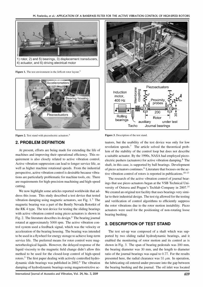
Figure 1. The test environment in the Jeffcott rotor layout.3
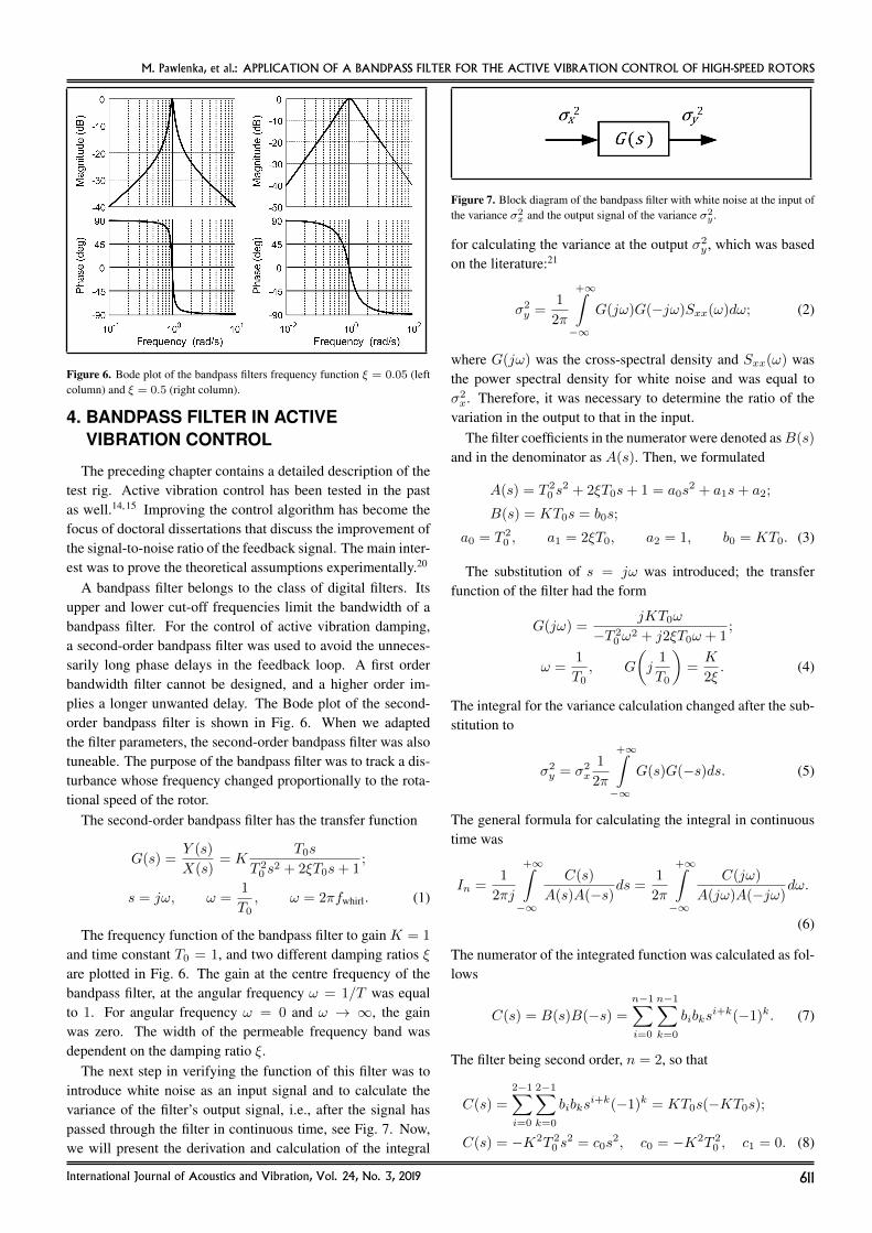
Figure 2. Test stand with piezoelectric actuators.4
2. PROBLEM DEFINITION
At present, efforts are being made for extending the life ofmachines and improving their operational efficiency. This re-quirement is also closely related to active vibration control.Active vibration suppression can lead to longer service life, aswell as higher machine rotational speeds. From the industrialperspective, active vibration control is desirable because vibra-tions are particularly problematic for machine tools, etc. Thereare requirements for high-precision machining and high-speedcutting.
We now highlight some articles reported worldwide that ad-dress this issue. This study described a test device that testedvibration damping using magnetic actuators, see Fig. 1.3 Themagnetic bearing was a part of the Bently Nevada Rotorkit ofthe RK 4 type. The test device for testing the sliding bearingswith active vibration control using piezo actuators is shown inFig. 2. The literature describes its design.4 The bearing journalrotated at approximately 5000 rpm. The active vibration con-trol system used a feedback signal, which was the velocity oracceleration of the bearing housing. The bearing was intendedto be used in a flywheel for energy storage to achieve long-termservice life. The preferred means for rotor control were mag-netorheological liquids. However, the delayed response of theliquid viscosity to the magnetic field change didn’t allow thismethod to be used for the closed-loop control of high-speedrotors.5 The first paper dealing with actively controlled hydro-dynamic slide bearings was published in 2002.6 The vibrationdamping of hydrodynamic bearings using magnetostrictive ac-
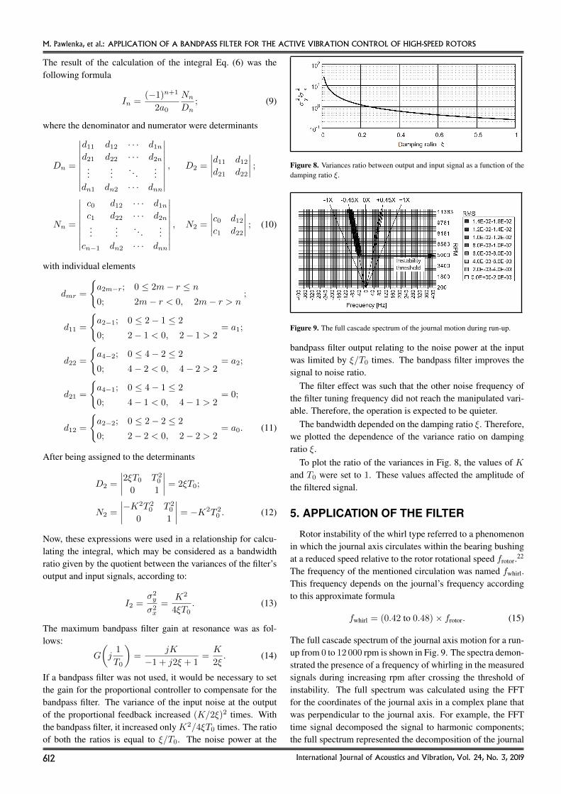
Figure 3. Description of the test stand.
tuators, but the usability of the test device was only for lowrevolution speeds.7 The article solved the theoretical prob-lem of the stability of the control loop but does not describea suitable actuator. By the 1990s, NASA had employed piezo-electric pushers (actuators) for active vibration damping.8 Theshaft, in this case, is supported by ball bearings. Developmentof piezo actuators continues.9 Literature that focuses on the ac-tive vibration control of rotors is reported in publications.10–13
The research of the active vibration control of journal bear-ings that use piezo actuators began at the VSB Technical Uni-versity of Ostrava and Prague’s Techlab Company in 2007.14
We created an original test facility that uses bearings very simi-lar to their industrial design. The test rig allowed for the testingand verification of control algorithms to efficiently suppressthe rotor vibrations due to the rotor motion instability. Piezoactuators were used for the positioning of non-rotating loosebearing bushing.
3. DESCRIPTION OF TEST STAND
The test set-up was composed of a shaft which was sup-ported by two sliding radial hydrodynamic bearings, and itenabled the monitoring of rotor motion and its control as isshown in Fig. 3. The span of bearing pedestals was 200 mm,the bearing diameter was 30 mm, and the length to diameterratio of the journal bearings was equal to 0.77. For the resultspresented here, the radial clearance was 55 µm. In operation,the lubricating oil entered under pressure into the gap betweenthe bearing bushing and the journal. The oil inlet was located
International Journal of Acoustics and Vibration, Vol. 24, No. 3, 2019 609

M. Pawlenka, et al.: APPLICATION OF A BANDPASS FILTER FOR THE ACTIVE VIBRATION CONTROL OF HIGH-SPEED ROTORS
in the horizontal plane of the bushing symmetry in the mid-dle of the bearing length. The inner surface of the bushingwas smooth without grooves. Special oil for high-speed spin-dle bearing of the OL-P03 type was used for testing (VG 10grade). Tests were carried out without preheating the lubricantat a normal temperature.
Measurement of the shaft position relative to the bearingbody was carried out in two perpendicular directions rotatedby 90 degrees from each other which are also perpendicular tothe axis of the shaft. Proximity probes are located near each oftwo bearings.
The bearing bushing was shifted in the radial direction bythe linear piezo actuators of the P-844.60 type. The P-884.60was a product of the Physik Instrumente Company. The piezoactuator required a low voltage amplifier with the 120 V peakvalue at the output. The piezo actuator travel range was 90 µm,the pushing force was 3000 N, and the pulling force was 700 N.Piezo actuator holders were designed to eliminate their bend-ing and torsional load. The design of the holder is available ina paper.15
The three-phase induction motor drove the rotor. The fre-quency inverter of the Commander SKA1200075 (ControlTechniques) type powered the driving motor. The maximumfrequency of the inverter was 400 Hz. Thus, the maximum mo-tor rotational speed was 24 000 rpm. The power of the induc-tion motor of the ATAS FT4C52G type was 500 W. The powerof the frequency inverter was 750 W. The laser speed sensor(Tacho) measured up to 250 000 rpm, which suited the spec-ified speed range. The Kalman filter reduced possible smallerrors of the rotational speed measurement.16–18
As it was mentioned, the position of the journal was mea-sured using proximity sensors. The principle of the proximitysensors was based on the capacitive sensors of the capaNCDTCS05 type originated from the MICRO-EPSILON company,see Fig. 4.19 These sensors had a measuring range of 0.5 mm.The capaNCDT system was based on the principle of the par-allel plate capacitor. Changing the distance of the two platesdetermined the capacitance change of the capacitor. For con-ductive materials, the tip of the sensor and the shaft surfaceformed the two electrodes. This theoretical principle was re-alized almost ideally in practice by designing the sensors asguard ring capacitors. In this case, it dealt with two capaci-tors. The conductive shaft surface connected these two capac-itors in series. The second electrode of both capacitors wasconnected to a control unit that contained a demodulator. Theadvantage of this distance measurement solution was that notarget grounding was required. If we measured by two sensorssimultaneously, both the two control units must be synchro-nized. The measurement error of the capacitance sensors isless than 1 µm.
The entire layout of the individual elements of the bearinghousing body, such as the sensors, the actuators, the bearingbushing and the journal, can be seen in Fig. 5. Active vibra-tion control of the journal bearing enabled the movable bearingbushing. As mentioned above, the bushing did not rotate, and
Figure 4. Principle of the capacitive proximity probe.18
the piezo actuators provided the bushing movement in two ra-dial directions.
The desired journal position in the horizontal and verticaldirections in a plane perpendicular to the axis of the shaft wascompared with the actual position. The calculated control er-ror was transformed by the controller into magnitudes of twomanipulated variables, which were the voltages for the piezoactuator amplifiers. All calculations were performed in thedSPACE signal processor. Amplified voltages govern the piezoactuator positions.
Figure 5. Schematic of the layout of the elements of the journal bearing.
610 International Journal of Acoustics and Vibration, Vol. 24, No. 3, 2019
M. Pawlenka, et al.: APPLICATION OF A BANDPASS FILTER FOR THE ACTIVE VIBRATION CONTROL OF HIGH-SPEED ROTORS
Figure 6. Bode plot of the bandpass filters frequency function ξ = 0.05 (leftcolumn) and ξ = 0.5 (right column).
4. BANDPASS FILTER IN ACTIVEVIBRATION CONTROL
The preceding chapter contains a detailed description of thetest rig. Active vibration control has been tested in the pastas well.14, 15 Improving the control algorithm has become thefocus of doctoral dissertations that discuss the improvement ofthe signal-to-noise ratio of the feedback signal. The main inter-est was to prove the theoretical assumptions experimentally.20
A bandpass filter belongs to the class of digital filters. Itsupper and lower cut-off frequencies limit the bandwidth of abandpass filter. For the control of active vibration damping,a second-order bandpass filter was used to avoid the unneces-sarily long phase delays in the feedback loop. A first orderbandwidth filter cannot be designed, and a higher order im-plies a longer unwanted delay. The Bode plot of the second-order bandpass filter is shown in Fig. 6. When we adaptedthe filter parameters, the second-order bandpass filter was alsotuneable. The purpose of the bandpass filter was to track a dis-turbance whose frequency changed proportionally to the rota-tional speed of the rotor.
The second-order bandpass filter has the transfer function
G(s) =Y (s)
X(s)= K
T0s
T 20 s
2 + 2ξT0s+ 1;
s = jω, ω =1
T0, ω = 2πfwhirl. (1)
The frequency function of the bandpass filter to gain K = 1
and time constant T0 = 1, and two different damping ratios ξare plotted in Fig. 6. The gain at the centre frequency of thebandpass filter, at the angular frequency ω = 1/T was equalto 1. For angular frequency ω = 0 and ω → ∞, the gainwas zero. The width of the permeable frequency band wasdependent on the damping ratio ξ.
The next step in verifying the function of this filter was tointroduce white noise as an input signal and to calculate thevariance of the filter’s output signal, i.e., after the signal haspassed through the filter in continuous time, see Fig. 7. Now,we will present the derivation and calculation of the integral
Figure 7. Block diagram of the bandpass filter with white noise at the input ofthe variance σ2
x and the output signal of the variance σ2y .
for calculating the variance at the output σ2y , which was based
on the literature:21
σ2y =
1
2π
+∞∫−∞
G(jω)G(−jω)Sxx(ω)dω; (2)
where G(jω) was the cross-spectral density and Sxx(ω) wasthe power spectral density for white noise and was equal toσ2x. Therefore, it was necessary to determine the ratio of the
variation in the output to that in the input.The filter coefficients in the numerator were denoted asB(s)
and in the denominator as A(s). Then, we formulated
A(s) = T 20 s
2 + 2ξT0s+ 1 = a0s2 + a1s+ a2;
B(s) = KT0s = b0s;
a0 = T 20 , a1 = 2ξT0, a2 = 1, b0 = KT0. (3)
The substitution of s = jω was introduced; the transferfunction of the filter had the form
G(jω) =jKT0ω
−T 20 ω
2 + j2ξT0ω + 1;
ω =1
T0, G
(j1
T0
)=K
2ξ. (4)
The integral for the variance calculation changed after the sub-stitution to
σ2y = σ2
x
1
2π
+∞∫−∞
G(s)G(−s)ds. (5)
The general formula for calculating the integral in continuoustime was
In =1
2πj
+∞∫−∞
C(s)
A(s)A(−s)ds =
1
2π
+∞∫−∞
C(jω)
A(jω)A(−jω)dω.
(6)
The numerator of the integrated function was calculated as fol-lows
C(s) = B(s)B(−s) =n−1∑i=0
n−1∑k=0
bibksi+k(−1)k. (7)
The filter being second order, n = 2, so that
C(s) =
2−1∑i=0
2−1∑k=0
bibksi+k(−1)k = KT0s(−KT0s);
C(s) = −K2T 20 s
2 = c0s2, c0 = −K2T 2
0 , c1 = 0. (8)
International Journal of Acoustics and Vibration, Vol. 24, No. 3, 2019 611
M. Pawlenka, et al.: APPLICATION OF A BANDPASS FILTER FOR THE ACTIVE VIBRATION CONTROL OF HIGH-SPEED ROTORS
The result of the calculation of the integral Eq. (6) was thefollowing formula
In =(−1)n+1
2a0
Nn
Dn; (9)
where the denominator and numerator were determinants
Dn =
∣∣∣∣∣∣∣∣∣d11 d12 · · · d1nd21 d22 · · · d2n
......
. . ....
dn1 dn2 · · · dnn
∣∣∣∣∣∣∣∣∣ , D2 =
∣∣∣∣d11 d12d21 d22
∣∣∣∣ ;
Nn =
∣∣∣∣∣∣∣∣∣c0 d12 · · · d1nc1 d22 · · · d2n...
.... . .
...cn−1 dn2 · · · dnn
∣∣∣∣∣∣∣∣∣ , N2 =
∣∣∣∣c0 d12c1 d22
∣∣∣∣ ; (10)
with individual elements
dmr =
{a2m−r; 0 ≤ 2m− r ≤ n0; 2m− r < 0, 2m− r > n
;
d11 =
{a2−1; 0 ≤ 2− 1 ≤ 2
0; 2− 1 < 0, 2− 1 > 2= a1;
d22 =
{a4−2; 0 ≤ 4− 2 ≤ 2
0; 4− 2 < 0, 4− 2 > 2= a2;
d21 =
{a4−1; 0 ≤ 4− 1 ≤ 2
0; 4− 1 < 0, 4− 1 > 2= 0;
d12 =
{a2−2; 0 ≤ 2− 2 ≤ 2
0; 2− 2 < 0, 2− 2 > 2= a0. (11)
After being assigned to the determinants
D2 =
∣∣∣∣2ξT0 T 20
0 1
∣∣∣∣ = 2ξT0;
N2 =
∣∣∣∣−K2T 20 T 2
0
0 1
∣∣∣∣ = −K2T 20 . (12)
Now, these expressions were used in a relationship for calcu-lating the integral, which may be considered as a bandwidthratio given by the quotient between the variances of the filter’soutput and input signals, according to:
I2 =σ2y
σ2x
=K2
4ξT0. (13)
The maximum bandpass filter gain at resonance was as fol-lows:
G
(j1
T0
)=
jK
−1 + j2ξ + 1=K
2ξ. (14)
If a bandpass filter was not used, it would be necessary to setthe gain for the proportional controller to compensate for thebandpass filter. The variance of the input noise at the outputof the proportional feedback increased (K/2ξ)2 times. Withthe bandpass filter, it increased onlyK2/4ξT0 times. The ratioof both the ratios is equal to ξ/T0. The noise power at the
Figure 8. Variances ratio between output and input signal as a function of thedamping ratio ξ.
Figure 9. The full cascade spectrum of the journal motion during run-up.
bandpass filter output relating to the noise power at the inputwas limited by ξ/T0 times. The bandpass filter improves thesignal to noise ratio.
The filter effect was such that the other noise frequency ofthe filter tuning frequency did not reach the manipulated vari-able. Therefore, the operation is expected to be quieter.
The bandwidth depended on the damping ratio ξ. Therefore,we plotted the dependence of the variance ratio on dampingratio ξ.
To plot the ratio of the variances in Fig. 8, the values of Kand T0 were set to 1. These values affected the amplitude ofthe filtered signal.
5. APPLICATION OF THE FILTER
Rotor instability of the whirl type referred to a phenomenonin which the journal axis circulates within the bearing bushingat a reduced speed relative to the rotor rotational speed frotor.22
The frequency of the mentioned circulation was named fwhirl.This frequency depends on the journal’s frequency accordingto this approximate formula
fwhirl = (0.42 to 0.48)× frotor. (15)
The full cascade spectrum of the journal axis motion for a run-up from 0 to 12 000 rpm is shown in Fig. 9. The spectra demon-strated the presence of a frequency of whirling in the measuredsignals during increasing rpm after crossing the threshold ofinstability. The full spectrum was calculated using the FFTfor the coordinates of the journal axis in a complex plane thatwas perpendicular to the journal axis. For example, the FFTtime signal decomposed the signal to harmonic components;the full spectrum represented the decomposition of the journal
612 International Journal of Acoustics and Vibration, Vol. 24, No. 3, 2019
M. Pawlenka, et al.: APPLICATION OF A BANDPASS FILTER FOR THE ACTIVE VIBRATION CONTROL OF HIGH-SPEED ROTORS
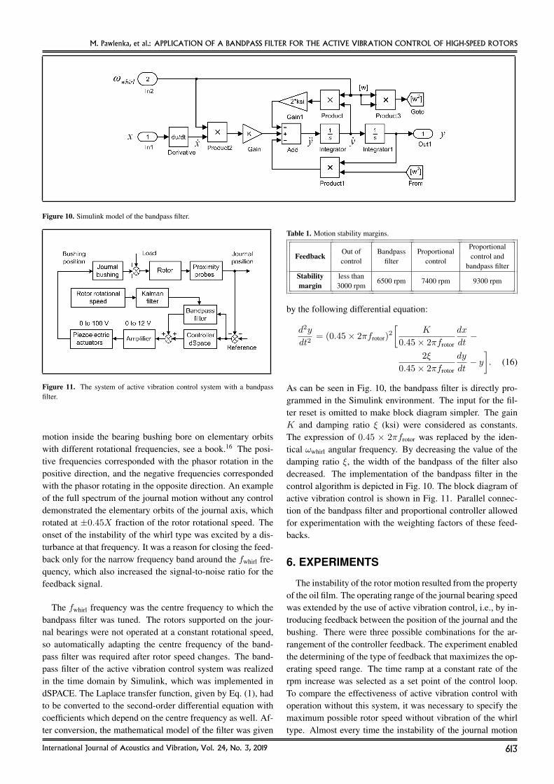
Figure 10. Simulink model of the bandpass filter.
Figure 11. The system of active vibration control system with a bandpassfilter.
motion inside the bearing bushing bore on elementary orbitswith different rotational frequencies, see a book.16 The posi-tive frequencies corresponded with the phasor rotation in thepositive direction, and the negative frequencies correspondedwith the phasor rotating in the opposite direction. An exampleof the full spectrum of the journal motion without any controldemonstrated the elementary orbits of the journal axis, whichrotated at ±0.45X fraction of the rotor rotational speed. Theonset of the instability of the whirl type was excited by a dis-turbance at that frequency. It was a reason for closing the feed-back only for the narrow frequency band around the fwhirl fre-quency, which also increased the signal-to-noise ratio for thefeedback signal.
The fwhirl frequency was the centre frequency to which thebandpass filter was tuned. The rotors supported on the jour-nal bearings were not operated at a constant rotational speed,so automatically adapting the centre frequency of the band-pass filter was required after rotor speed changes. The band-pass filter of the active vibration control system was realizedin the time domain by Simulink, which was implemented indSPACE. The Laplace transfer function, given by Eq. (1), hadto be converted to the second-order differential equation withcoefficients which depend on the centre frequency as well. Af-ter conversion, the mathematical model of the filter was given
Table 1. Motion stability margins.
Out of Bandpass ProportionalProportional
Feedbackcontrol filter control
control andbandpass filter
Stability less than6500 rpm 7400 rpm 9300 rpm
margin 3000 rpm
by the following differential equation:
d2y
dt2= (0.45× 2πfrotor)
2
[K
0.45× 2πfrotor
dx
dt−
2ξ
0.45× 2πfrotor
dy
dt− y]. (16)
As can be seen in Fig. 10, the bandpass filter is directly pro-grammed in the Simulink environment. The input for the fil-ter reset is omitted to make block diagram simpler. The gainK and damping ratio ξ (ksi) were considered as constants.The expression of 0.45 × 2πfrotor was replaced by the iden-tical ωwhirl angular frequency. By decreasing the value of thedamping ratio ξ, the width of the bandpass of the filter alsodecreased. The implementation of the bandpass filter in thecontrol algorithm is depicted in Fig. 10. The block diagram ofactive vibration control is shown in Fig. 11. Parallel connec-tion of the bandpass filter and proportional controller allowedfor experimentation with the weighting factors of these feed-backs.
6. EXPERIMENTS
The instability of the rotor motion resulted from the propertyof the oil film. The operating range of the journal bearing speedwas extended by the use of active vibration control, i.e., by in-troducing feedback between the position of the journal and thebushing. There were three possible combinations for the ar-rangement of the controller feedback. The experiment enabledthe determining of the type of feedback that maximizes the op-erating speed range. The time ramp at a constant rate of therpm increase was selected as a set point of the control loop.To compare the effectiveness of active vibration control withoperation without this system, it was necessary to specify themaximum possible rotor speed without vibration of the whirltype. Almost every time the instability of the journal motion
International Journal of Acoustics and Vibration, Vol. 24, No. 3, 2019 613
M. Pawlenka, et al.: APPLICATION OF A BANDPASS FILTER FOR THE ACTIVE VIBRATION CONTROL OF HIGH-SPEED ROTORS
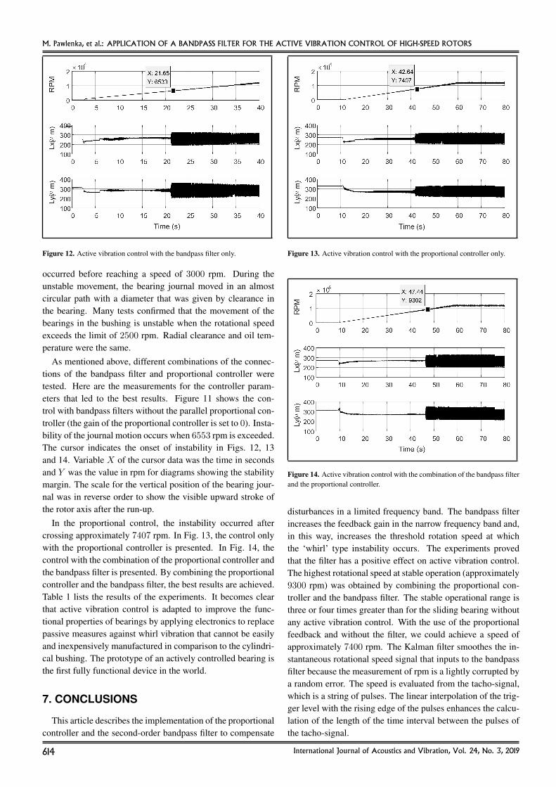
Figure 12. Active vibration control with the bandpass filter only.
occurred before reaching a speed of 3000 rpm. During theunstable movement, the bearing journal moved in an almostcircular path with a diameter that was given by clearance inthe bearing. Many tests confirmed that the movement of thebearings in the bushing is unstable when the rotational speedexceeds the limit of 2500 rpm. Radial clearance and oil tem-perature were the same.
As mentioned above, different combinations of the connec-tions of the bandpass filter and proportional controller weretested. Here are the measurements for the controller param-eters that led to the best results. Figure 11 shows the con-trol with bandpass filters without the parallel proportional con-troller (the gain of the proportional controller is set to 0). Insta-bility of the journal motion occurs when 6553 rpm is exceeded.The cursor indicates the onset of instability in Figs. 12, 13and 14. Variable X of the cursor data was the time in secondsand Y was the value in rpm for diagrams showing the stabilitymargin. The scale for the vertical position of the bearing jour-nal was in reverse order to show the visible upward stroke ofthe rotor axis after the run-up.
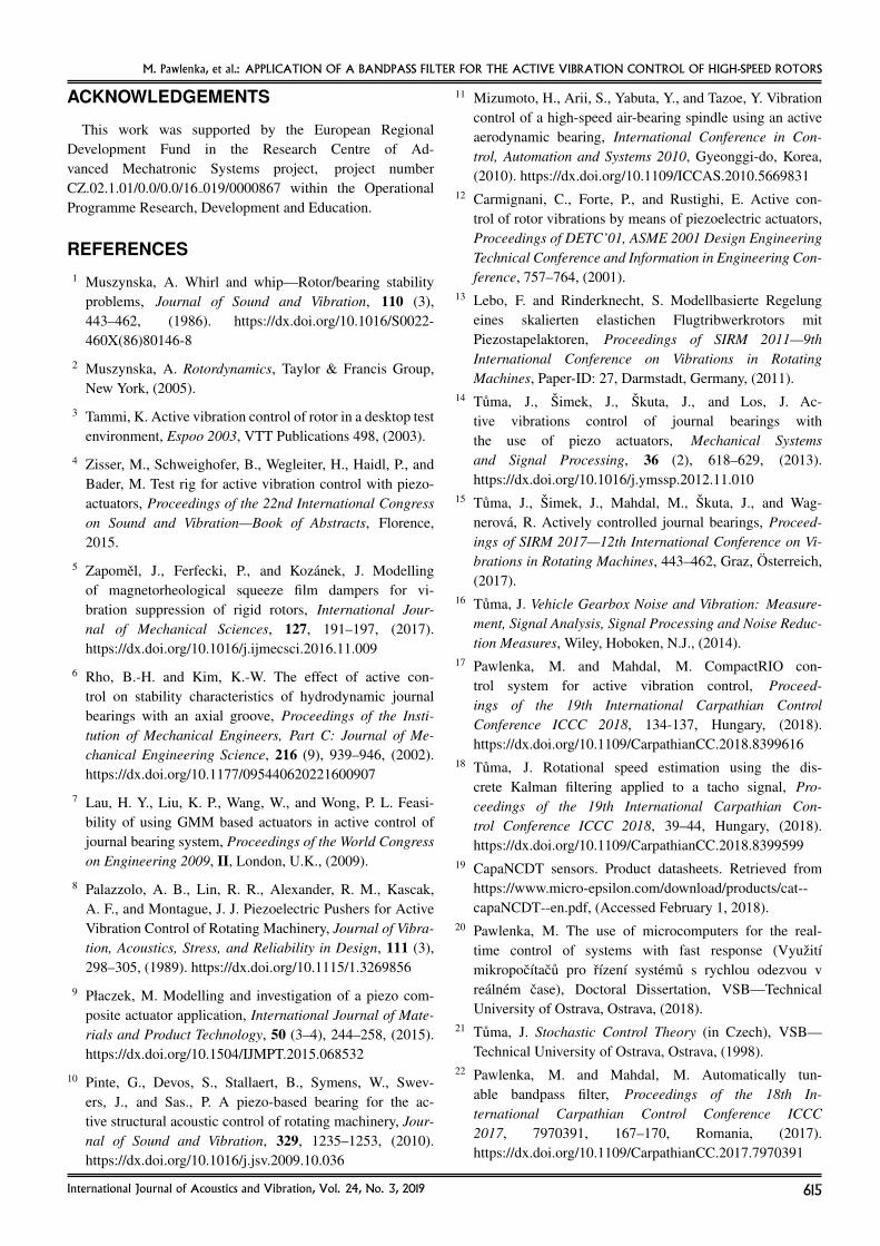
In the proportional control, the instability occurred aftercrossing approximately 7407 rpm. In Fig. 13, the control onlywith the proportional controller is presented. In Fig. 14, thecontrol with the combination of the proportional controller andthe bandpass filter is presented. By combining the proportionalcontroller and the bandpass filter, the best results are achieved.Table 1 lists the results of the experiments. It becomes clearthat active vibration control is adapted to improve the func-tional properties of bearings by applying electronics to replacepassive measures against whirl vibration that cannot be easilyand inexpensively manufactured in comparison to the cylindri-cal bushing. The prototype of an actively controlled bearing isthe first fully functional device in the world.
7. CONCLUSIONS
This article describes the implementation of the proportionalcontroller and the second-order bandpass filter to compensate
Figure 13. Active vibration control with the proportional controller only.
Figure 14. Active vibration control with the combination of the bandpass filterand the proportional controller.
disturbances in a limited frequency band. The bandpass filterincreases the feedback gain in the narrow frequency band and,in this way, increases the threshold rotation speed at whichthe ‘whirl’ type instability occurs. The experiments provedthat the filter has a positive effect on active vibration control.The highest rotational speed at stable operation (approximately9300 rpm) was obtained by combining the proportional con-troller and the bandpass filter. The stable operational range isthree or four times greater than for the sliding bearing withoutany active vibration control. With the use of the proportionalfeedback and without the filter, we could achieve a speed ofapproximately 7400 rpm. The Kalman filter smoothes the in-stantaneous rotational speed signal that inputs to the bandpassfilter because the measurement of rpm is a lightly corrupted bya random error. The speed is evaluated from the tacho-signal,which is a string of pulses. The linear interpolation of the trig-ger level with the rising edge of the pulses enhances the calcu-lation of the length of the time interval between the pulses ofthe tacho-signal.
614 International Journal of Acoustics and Vibration, Vol. 24, No. 3, 2019
M. Pawlenka, et al.: APPLICATION OF A BANDPASS FILTER FOR THE ACTIVE VIBRATION CONTROL OF HIGH-SPEED ROTORS
ACKNOWLEDGEMENTS
This work was supported by the European RegionalDevelopment Fund in the Research Centre of Ad-vanced Mechatronic Systems project, project numberCZ.02.1.01/0.0/0.0/16 019/0000867 within the OperationalProgramme Research, Development and Education.
REFERENCES1 Muszynska, A. Whirl and whip—Rotor/bearing stability
problems, Journal of Sound and Vibration, 110 (3),443–462, (1986). https://dx.doi.org/10.1016/S0022-460X(86)80146-8
2 Muszynska, A. Rotordynamics, Taylor & Francis Group,New York, (2005).
3 Tammi, K. Active vibration control of rotor in a desktop testenvironment, Espoo 2003, VTT Publications 498, (2003).
4 Zisser, M., Schweighofer, B., Wegleiter, H., Haidl, P., andBader, M. Test rig for active vibration control with piezo-actuators, Proceedings of the 22nd International Congresson Sound and Vibration—Book of Abstracts, Florence,2015.
5 Zapomel, J., Ferfecki, P., and Kozanek, J. Modellingof magnetorheological squeeze film dampers for vi-bration suppression of rigid rotors, International Jour-nal of Mechanical Sciences, 127, 191–197, (2017).https://dx.doi.org/10.1016/j.ijmecsci.2016.11.009
6 Rho, B.-H. and Kim, K.-W. The effect of active con-trol on stability characteristics of hydrodynamic journalbearings with an axial groove, Proceedings of the Insti-tution of Mechanical Engineers, Part C: Journal of Me-chanical Engineering Science, 216 (9), 939–946, (2002).https://dx.doi.org/10.1177/095440620221600907
7 Lau, H. Y., Liu, K. P., Wang, W., and Wong, P. L. Feasi-bility of using GMM based actuators in active control ofjournal bearing system, Proceedings of the World Congresson Engineering 2009, II, London, U.K., (2009).
8 Palazzolo, A. B., Lin, R. R., Alexander, R. M., Kascak,A. F., and Montague, J. J. Piezoelectric Pushers for ActiveVibration Control of Rotating Machinery, Journal of Vibra-tion, Acoustics, Stress, and Reliability in Design, 111 (3),298–305, (1989). https://dx.doi.org/10.1115/1.3269856
9 Płaczek, M. Modelling and investigation of a piezo com-posite actuator application, International Journal of Mate-rials and Product Technology, 50 (3–4), 244–258, (2015).https://dx.doi.org/10.1504/IJMPT.2015.068532
10 Pinte, G., Devos, S., Stallaert, B., Symens, W., Swev-ers, J., and Sas., P. A piezo-based bearing for the ac-tive structural acoustic control of rotating machinery, Jour-nal of Sound and Vibration, 329, 1235–1253, (2010).https://dx.doi.org/10.1016/j.jsv.2009.10.036
11 Mizumoto, H., Arii, S., Yabuta, Y., and Tazoe, Y. Vibrationcontrol of a high-speed air-bearing spindle using an activeaerodynamic bearing, International Conference in Con-trol, Automation and Systems 2010, Gyeonggi-do, Korea,(2010). https://dx.doi.org/10.1109/ICCAS.2010.5669831
12 Carmignani, C., Forte, P., and Rustighi, E. Active con-trol of rotor vibrations by means of piezoelectric actuators,Proceedings of DETC’01, ASME 2001 Design EngineeringTechnical Conference and Information in Engineering Con-ference, 757–764, (2001).
13 Lebo, F. and Rinderknecht, S. Modellbasierte Regelungeines skalierten elastichen Flugtribwerkrotors mitPiezostapelaktoren, Proceedings of SIRM 2011—9thInternational Conference on Vibrations in RotatingMachines, Paper-ID: 27, Darmstadt, Germany, (2011).
14 Tuma, J., Simek, J., Skuta, J., and Los, J. Ac-tive vibrations control of journal bearings withthe use of piezo actuators, Mechanical Systemsand Signal Processing, 36 (2), 618–629, (2013).https://dx.doi.org/10.1016/j.ymssp.2012.11.010
15 Tuma, J., Simek, J., Mahdal, M., Skuta, J., and Wag-nerova, R. Actively controlled journal bearings, Proceed-ings of SIRM 2017—12th International Conference on Vi-brations in Rotating Machines, 443–462, Graz, Osterreich,(2017).
16 Tuma, J. Vehicle Gearbox Noise and Vibration: Measure-ment, Signal Analysis, Signal Processing and Noise Reduc-tion Measures, Wiley, Hoboken, N.J., (2014).
17 Pawlenka, M. and Mahdal, M. CompactRIO con-trol system for active vibration control, Proceed-ings of the 19th International Carpathian ControlConference ICCC 2018, 134-137, Hungary, (2018).https://dx.doi.org/10.1109/CarpathianCC.2018.8399616
18 Tuma, J. Rotational speed estimation using the dis-crete Kalman filtering applied to a tacho signal, Pro-ceedings of the 19th International Carpathian Con-trol Conference ICCC 2018, 39–44, Hungary, (2018).https://dx.doi.org/10.1109/CarpathianCC.2018.8399599
19 CapaNCDT sensors. Product datasheets. Retrieved fromhttps://www.micro-epsilon.com/download/products/cat--capaNCDT--en.pdf, (Accessed February 1, 2018).
20 Pawlenka, M. The use of microcomputers for the real-time control of systems with fast response (Vyuzitımikropocıtacu pro rızenı systemu s rychlou odezvou vrealnem case), Doctoral Dissertation, VSB—TechnicalUniversity of Ostrava, Ostrava, (2018).
21 Tuma, J. Stochastic Control Theory (in Czech), VSB—Technical University of Ostrava, Ostrava, (1998).
22 Pawlenka, M. and Mahdal, M. Automatically tun-able bandpass filter, Proceedings of the 18th In-ternational Carpathian Control Conference ICCC2017, 7970391, 167–170, Romania, (2017).https://dx.doi.org/10.1109/CarpathianCC.2017.7970391
International Journal of Acoustics and Vibration, Vol. 24, No. 3, 2019 615