application note quickstick 100 power cable sizing …€¦ · quickstick 100 power cable sizing...
TRANSCRIPT

TECHNICAL SUPPORT NOTICE 990000711 Rev. C
139 Barnum Road, Devens, MA 01434 Page 1 of 19 FM-752-012 Rev. A
© MagneMotion, Inc. – All Rights Reserved. Information included in this document is MagneMotion proprietary information and is provided for the use of MMI customers only and cannot be distributed, reproduced, or sold without the express written permission of MagneMotion, Inc. In no event will MMI be responsible or liable for indirect or consequential damages resulting from the use or application of this information.
APPLICATION NOTE QuickStick 100 Power Cable Sizing and Selection
Purpose
This document will provide an introduction to power supply cables and selecting a power cabling
architecture for a QuickStick 100 system. This document provides a limited selection of
background knowledge required for this analysis. Following the instructions in the document is
not a replacement for analysis of your system’s power wiring by a qualified electrical engineer.
Introduction
When designing a power transmission system, it is important to take into consideration that the
voltage experienced at the supply may not be the same as the voltage at the QuickStick end of
the power wiring. Voltage drop or regeneration of power can drive the voltage at the QuickStick
higher or lower than what the supply provides.
Like any other electrical component, the QuickStick 100 motors have a defined operating voltage
range. Operating below or above this range can result in the motor turning off or being damaged.
While the motor has protections in place to prevent this damage, the power supply system should
be designed so that the voltage limits are not exceeded during normal operating conditions.
The allowable standing (non-operational) voltage input range to the QuickStick 100 motor is
48V ± 5%.
The allowable voltage input range during operation on a QuickStick 100 motor is 42.5-57V, with
a nominal voltage of 48V. MagneMotion recommends allowing for a minimum tolerance of
0.5V from these values when designing power supply wiring.
The limits and curves expressed in this document are valid for software
Node Controller version 2.2.23
Master version 1.4.31
Slave version 2.2.7
or newer.
TECHNICAL SUPPORT NOTICE 990000711 Rev. C
139 Barnum Road, Devens, MA 01434 Page 2 of 19 FM-752-012 Rev. A
© MagneMotion, Inc. – All Rights Reserved. Information included in this document is MagneMotion proprietary information and is provided for the use of MMI customers only and cannot be distributed, reproduced, or sold without the express written permission of MagneMotion, Inc. In no event will MMI be responsible or liable for indirect or consequential damages resulting from the use or application of this information.
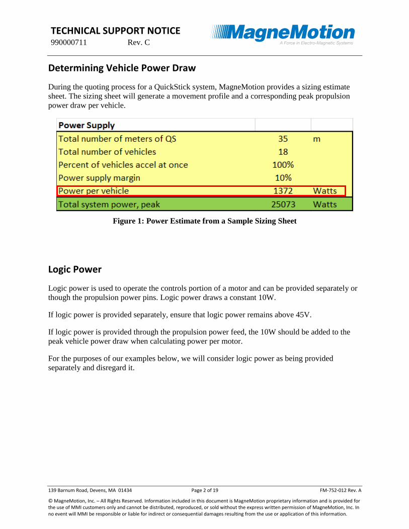
Determining Vehicle Power Draw
During the quoting process for a QuickStick system, MagneMotion provides a sizing estimate
sheet. The sizing sheet will generate a movement profile and a corresponding peak propulsion
power draw per vehicle.
Figure 1: Power Estimate from a Sample Sizing Sheet
Logic Power
Logic power is used to operate the controls portion of a motor and can be provided separately or
though the propulsion power pins. Logic power draws a constant 10W.
If logic power is provided separately, ensure that logic power remains above 45V.
If logic power is provided through the propulsion power feed, the 10W should be added to the
peak vehicle power draw when calculating power per motor.
For the purposes of our examples below, we will consider logic power as being provided
separately and disregard it.

TECHNICAL SUPPORT NOTICE 990000711 Rev. C
139 Barnum Road, Devens, MA 01434 Page 3 of 19 FM-752-012 Rev. A
© MagneMotion, Inc. – All Rights Reserved. Information included in this document is MagneMotion proprietary information and is provided for the use of MMI customers only and cannot be distributed, reproduced, or sold without the express written permission of MagneMotion, Inc. In no event will MMI be responsible or liable for indirect or consequential damages resulting from the use or application of this information.
Propulsion Power
Propulsion power refers to the power used to accelerate and decelerate a vehicle. This is the main
function that consumes power and will vary based on the activity of the motor.
Figure 2: Example of Power Consumption for a Single Movement from Sizing Sheet
The vehicle motion will consume power when it accelerates and regenerate power when it
decelerates. The locations on the system where peak power and regeneration are reached will
depend on the move profile being used.
Figure 3: Location of Power Peaks During Motion
TECHNICAL SUPPORT NOTICE 990000711 Rev. C
139 Barnum Road, Devens, MA 01434 Page 4 of 19 FM-752-012 Rev. A
© MagneMotion, Inc. – All Rights Reserved. Information included in this document is MagneMotion proprietary information and is provided for the use of MMI customers only and cannot be distributed, reproduced, or sold without the express written permission of MagneMotion, Inc. In no event will MMI be responsible or liable for indirect or consequential damages resulting from the use or application of this information.
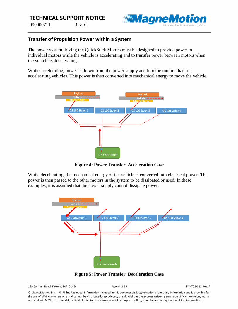
Transfer of Propulsion Power within a System
The power system driving the QuickStick Motors must be designed to provide power to
individual motors while the vehicle is accelerating and to transfer power between motors when
the vehicle is decelerating.
While accelerating, power is drawn from the power supply and into the motors that are
accelerating vehicles. This power is then converted into mechanical energy to move the vehicle.
Figure 4: Power Transfer, Acceleration Case
While decelerating, the mechanical energy of the vehicle is converted into electrical power. This
power is then passed to the other motors in the system to be dissipated or used. In these
examples, it is assumed that the power supply cannot dissipate power.
Figure 5: Power Transfer, Deceleration Case

TECHNICAL SUPPORT NOTICE 990000711 Rev. C
139 Barnum Road, Devens, MA 01434 Page 5 of 19 FM-752-012 Rev. A
© MagneMotion, Inc. – All Rights Reserved. Information included in this document is MagneMotion proprietary information and is provided for the use of MMI customers only and cannot be distributed, reproduced, or sold without the express written permission of MagneMotion, Inc. In no event will MMI be responsible or liable for indirect or consequential damages resulting from the use or application of this information.
Acceleration
While the vehicle is accelerating, the motor is drawing power from the power supply system. In
the worst case, a single motor can draw up to the value for peak power per vehicle shown in the
sizing estimate sheet while the vehicle is finishing its acceleration.
The current to each motor in a system at a given time will depend on system behavior and
vehicle size. When sizing cables, the worst case power draw, current, and vehicle movements
should always be used.
Example – Single Motor
The first case that we will consider is a single motor connected directly to the power supply.
Figure 6: Example of a Power System for Single Motor
In the figure above:
Local Vdc is the voltage at QuickStick
I is the current in the cable
Rc is the resistance of the cable (1 way)
Note that half of the total cable resistance is on one conductor and the other half of the total
resistance is on the return conductor.
By Kirchhoff’s Voltage Law, all of the voltages in the loop must sum to zero. VC refers to the
voltage drop within a cable.
48𝑉 − 𝑉𝐶 − 𝐿𝑜𝑐𝑎𝑙 𝑉𝑑𝑐 − 𝑉𝐶 = 0
48𝑉 − 𝐿𝑜𝑐𝑎𝑙 𝑉𝑑𝑐 = 2𝑉𝐶

TECHNICAL SUPPORT NOTICE 990000711 Rev. C
139 Barnum Road, Devens, MA 01434 Page 6 of 19 FM-752-012 Rev. A
© MagneMotion, Inc. – All Rights Reserved. Information included in this document is MagneMotion proprietary information and is provided for the use of MMI customers only and cannot be distributed, reproduced, or sold without the express written permission of MagneMotion, Inc. In no event will MMI be responsible or liable for indirect or consequential damages resulting from the use or application of this information.
By Ohm’s Law, the voltage across a component is equal to the resistance of that component
multiplied by the current through that component.
48𝑉 − 𝐿𝑜𝑐𝑎𝑙 𝑉𝑑𝑐 = 2𝐼𝑅𝐶
The term 48𝑉 − 𝐿𝑜𝑐𝑎𝑙 𝑉𝑑𝑐 is referred to as “voltage drop” as this is the deviation from the
nominal 48V power supply voltage experienced at the load end of the power system.
Based on Kirchhoff’s Current Law, the currents through each element of the system are the
same. Using the Power Law, divide the peak power draw from the motor by the local voltage at
the motor to determine what this current is. For these examples, use the peak power draw
identified in Figure 1 of 1372W.
As MagneMotion recommends sizing cables so that the voltage drop is not within 0.5V of the
low voltage limit, a Local Vdc of 43V will be used for this example.
𝐼 = 𝑃
𝑉=
1372𝑊
43𝑉= 31.9𝐴
48𝑉 − 𝐿𝑜𝑐𝑎𝑙 𝑉𝑑𝑐 = 2𝐼𝑅𝐶
48𝑉 − 43𝑉 = 2 (31.9𝐴)𝑅𝑐
𝑅𝐶 =48𝑉 − 43𝑉
2 (31.9𝐴)= 0.078Ω
So in this case, a cable resistance of less than 0.078Ω would be required. If minimum allowable
local voltage of 42.5V is used, the calculations are as follows.
𝐼 = 𝑃
𝑉=
1372𝑊
42.5𝑉= 32.28𝐴
48𝑉 − 𝐿𝑜𝑐𝑎𝑙 𝑉𝑑𝑐 = 2𝐼𝑅𝐶
48𝑉 − 42.5𝑉 = 2 (32.28𝐴)𝑅𝑐
𝑅𝐶 =48𝑉 − 42.5𝑉
2 (32.28𝐴)= 0.085Ω
As shown, the cable resistance must be selected based on the desired voltage at the QuickStick.
This calculated cable resistance can then be used to select appropriate sized cabling for the
system.

TECHNICAL SUPPORT NOTICE 990000711 Rev. C
139 Barnum Road, Devens, MA 01434 Page 7 of 19 FM-752-012 Rev. A
© MagneMotion, Inc. – All Rights Reserved. Information included in this document is MagneMotion proprietary information and is provided for the use of MMI customers only and cannot be distributed, reproduced, or sold without the express written permission of MagneMotion, Inc. In no event will MMI be responsible or liable for indirect or consequential damages resulting from the use or application of this information.
Example – Series Bus
The preferred architecture for a QuickStick power bus is a number of junction boxes (shown in
green in Figure 7) connected in series to form a single, low resistance, power bus. Each junction
box (terminals shown in green below) supplies a certain number of motors. Both logic and
propulsion power connections are shown below, but only propulsion power is used for the
calculations.
Figure 7: Example Power System for Series Bus Architecture
Kirchhoff’s Current Law must be applied in order to determine which current must be used when
evaluating voltage drop across a particular component. In this case, application of Kirchhoff’s
Current Law shows that the current in the single main bus line will decrease the further from the
bus the motor is located. The current to each motor will depend on system behavior and vehicle
size. When sizing cables, the worst case power draw and current should always be used.
The equation for modeling the cable resistance and voltage at motor 1 (V1) would be as follows:
48𝑉 − 𝑉1 = [2(𝐼1 + 𝐼2 + 𝐼3 + 𝐼4 + 𝐼5)(𝑅1 + 𝑅𝐽𝐵1)] + [2𝐼1𝑅4]
The equation for modeling the cable resistance and voltage at motor 5 (V5) would be as follows:
48𝑉 − 𝑉5 = [2(𝐼1 + 𝐼2 + 𝐼3 + 𝐼4 + 𝐼5)(𝑅1 + 𝑅𝐽𝐵1)] + [2(𝐼3 + 𝐼4 + 𝐼5)(𝑅2 + 𝑅𝐽𝐵2)]
+ [2(𝐼5)(𝑅3 + 𝑅𝐽𝐵3 + 𝑅8)]

TECHNICAL SUPPORT NOTICE 990000711 Rev. C
139 Barnum Road, Devens, MA 01434 Page 8 of 19 FM-752-012 Rev. A
© MagneMotion, Inc. – All Rights Reserved. Information included in this document is MagneMotion proprietary information and is provided for the use of MMI customers only and cannot be distributed, reproduced, or sold without the express written permission of MagneMotion, Inc. In no event will MMI be responsible or liable for indirect or consequential damages resulting from the use or application of this information.
Example – Central Bus
One type of power architecture that has been used for certain systems is the central bus
architecture. A number of QuickSticks are attached to a local junction box supplying propulsion
power (Junction box terminals shown in green in Figure 8). Each junction box is then routed
back to a central power cabinet, where they are connected to a central bus line connected to the
power supply.
Figure 8: Example Power System for Central Bus Architecture
In this case, Kirchhoff’s Current Law shows that the currents become smaller as the single bus
splits into multiple cables. In this example, the equation by Ohm’s Law for voltage across the
first junction box (JB1) would be
𝑉𝐽𝐵1 = (𝐼1 + 𝐼2 + 𝐼3 + 𝐼4 + 𝐼5)𝑅𝐽𝐵1
The equation for modeling the cable resistance and voltage at motor 1 (V1) would be as follows:
48𝑉 − 𝑉1 = [2(𝐼1 + 𝐼2 + 𝐼3 + 𝐼4 + 𝐼5)(𝑅1 + 𝑅𝐽𝐵1)] + [2(𝐼1 + 𝐼2)(𝑅2 + 𝑅𝐽𝐵2)] + [2𝐼1𝑅3]

TECHNICAL SUPPORT NOTICE 990000711 Rev. C
139 Barnum Road, Devens, MA 01434 Page 9 of 19 FM-752-012 Rev. A
© MagneMotion, Inc. – All Rights Reserved. Information included in this document is MagneMotion proprietary information and is provided for the use of MMI customers only and cannot be distributed, reproduced, or sold without the express written permission of MagneMotion, Inc. In no event will MMI be responsible or liable for indirect or consequential damages resulting from the use or application of this information.
Deceleration (Regeneration)
In addition to providing the power used to accelerate a vehicle, the wiring must also be designed
to manage power regenerated by a vehicle as it stops. In general, if a system is designed to
support supplying power during acceleration, it will also support the deceleration case.
Power Regenerated by a Vehicle
When a vehicle slows to a stop, the mechanical energy of the vehicle is converted to electrical
energy on the power bus. This energy must then be dissipated to avoid raising the voltage of the
bus beyond the acceptable limit of 57V.
Power is being provided to the stator coils to actively slow down the vehicle so the net
“effective” regeneration power is lower than the power required to accelerate the vehicle. The
reduction is based on a number of factors, but a conservative first estimate is that the net
effective regeneration power is about 75% of the acceleration power. For the example power
draw used in Example – Single Motor (page 5):
𝑃𝑟𝑒𝑔𝑒𝑛 = 𝑃𝑎𝑐𝑐 ∗ 0.75 = 1372𝑊 ∗ 0.75 = 1029𝑊
Note that as the vehicle slows down under constant deceleration, the regeneration power will
drop linearly with speed. The power found above is the peak regeneration power.
TECHNICAL SUPPORT NOTICE 990000711 Rev. C
139 Barnum Road, Devens, MA 01434 Page 10 of 19 FM-752-012 Rev. A
© MagneMotion, Inc. – All Rights Reserved. Information included in this document is MagneMotion proprietary information and is provided for the use of MMI customers only and cannot be distributed, reproduced, or sold without the express written permission of MagneMotion, Inc. In no event will MMI be responsible or liable for indirect or consequential damages resulting from the use or application of this information.
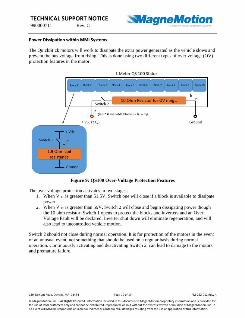
Power Dissipation within MMI Systems
The QuickStick motors will work to dissipate the extra power generated as the vehicle slows and
prevent the bus voltage from rising. This is done using two different types of over voltage (OV)
protection features in the motor.
Figure 9: QS100 Over-Voltage Protection Features
The over voltage protection activates in two stages:
1. When VDC is greater than 51.5V, Switch one will close if a block is available to dissipate
power
2. When VDC is greater than 59V, Switch 2 will close and begin dissipating power though
the 10 ohm resistor. Switch 1 opens to protect the blocks and inverters and an Over
Voltage Fault will be declared. Inverter shut down will eliminate regeneration, and will
also lead to uncontrolled vehicle motion.
Switch 2 should not close during normal operation. It is for protection of the motors in the event
of an unusual event, not something that should be used on a regular basis during normal
operation. Continuously activating and deactivating Switch 2, can lead to damage to the motors
and premature failure.
TECHNICAL SUPPORT NOTICE 990000711 Rev. C
139 Barnum Road, Devens, MA 01434 Page 11 of 19 FM-752-012 Rev. A
© MagneMotion, Inc. – All Rights Reserved. Information included in this document is MagneMotion proprietary information and is provided for the use of MMI customers only and cannot be distributed, reproduced, or sold without the express written permission of MagneMotion, Inc. In no event will MMI be responsible or liable for indirect or consequential damages resulting from the use or application of this information.
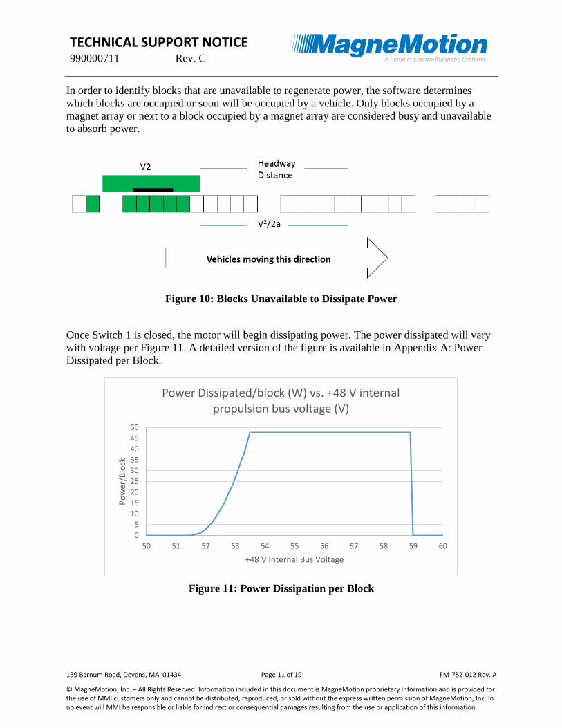
In order to identify blocks that are unavailable to regenerate power, the software determines
which blocks are occupied or soon will be occupied by a vehicle. Only blocks occupied by a
magnet array or next to a block occupied by a magnet array are considered busy and unavailable
to absorb power.
Figure 10: Blocks Unavailable to Dissipate Power
Once Switch 1 is closed, the motor will begin dissipating power. The power dissipated will vary
with voltage per Figure 11. A detailed version of the figure is available in Appendix A: Power
Dissipated per Block.
Figure 11: Power Dissipation per Block
0
5
10
15
20
25
30
35
40
45
50
50 51 52 53 54 55 56 57 58 59 60
Po
wer
/Blo
ck
+48 V Internal Bus Voltage
Power Dissipated/block (W) vs. +48 V internal propulsion bus voltage (V)

TECHNICAL SUPPORT NOTICE 990000711 Rev. C
139 Barnum Road, Devens, MA 01434 Page 12 of 19 FM-752-012 Rev. A
© MagneMotion, Inc. – All Rights Reserved. Information included in this document is MagneMotion proprietary information and is provided for the use of MMI customers only and cannot be distributed, reproduced, or sold without the express written permission of MagneMotion, Inc. In no event will MMI be responsible or liable for indirect or consequential damages resulting from the use or application of this information.
Example – Two Motors
The first example to be considered is a single motor dissipating power and a single motor
inputting power. To simplify the analysis, the following assumptions were made for this
example:
All cable resistances are identical
The magnet array and its adjacent blocks occupy exactly (1) 1-meter motor (10 motor
blocks per motor)
The vehicle is just beginning to decelerate at that location
The power supply has a diode and is not capable of absorbing power
Figure 12: Single Vehicle Decelerating with Two Motors
V1 can be set to 57V, the maximum allowable voltage for the system during normal operation.
Based on this, the Power Law can be used to find the current i1.
𝑖1 =𝑃1
𝑉1=
400𝑊
57𝑉= 7.02𝐴
By Kirchhoff’s Current Law, the sum of the currents entering and leaving the junction near the
power supply must be zero.
𝑖1 − 𝑖2 = 0
𝑖1 = 𝑖2
Motor 2 has no magnet array over it, so all 10 blocks are available to dissipate power. Assuming
that power loss in the cables is considered to be negligible, this means that the power dissipated
per block is
400𝑊
10 𝑏𝑙𝑜𝑐𝑘𝑠= 40 𝑊 𝑏𝑙𝑜𝑐𝑘⁄

TECHNICAL SUPPORT NOTICE 990000711 Rev. C
139 Barnum Road, Devens, MA 01434 Page 13 of 19 FM-752-012 Rev. A
© MagneMotion, Inc. – All Rights Reserved. Information included in this document is MagneMotion proprietary information and is provided for the use of MMI customers only and cannot be distributed, reproduced, or sold without the express written permission of MagneMotion, Inc. In no event will MMI be responsible or liable for indirect or consequential damages resulting from the use or application of this information.
Using Figure 17: Power Dissipated per Block, this puts V2 at 53.3V. Using Ohm’s Law, the
maximum allowable resistance in the cables can be found.
𝑉1 − 𝑉2 = 𝑖1𝑅𝑐 + 𝑖2𝑅𝑐 = 2𝑖1𝑅𝑐
57𝑉 − 53.3𝑉 = 2(7.02𝐴)𝑅𝑐
𝑅𝑐 =57𝑉 − 53.3𝑉
2(7.02𝐴)= 0.26Ω
Example – Central Bus with One Vehicle
Another example to be considered is a single vehicle decelerating on a path. Use the same
assumptions as in the previous example and the example sizing for regeneration power.
Figure 13: Single Vehicle Decelerating with Four Motors
V1 can be set to 57V, the maximum allowable voltage for the system during normal operation.
Based on this, the Power Law can be used to find the current i1.
𝑖1 =𝑃1
𝑉1=
1029𝑊
57𝑉= 18.05𝐴
By Kirchhoff’s Current Law, the sum of the currents entering and leaving the junction near the
power supply must be zero.
𝑖1 − 𝑖2 − 𝑖3 − 𝑖4 = 0
𝑖1 = 𝑖2 + 𝑖3 + 𝑖4
TECHNICAL SUPPORT NOTICE 990000711 Rev. C
139 Barnum Road, Devens, MA 01434 Page 14 of 19 FM-752-012 Rev. A
© MagneMotion, Inc. – All Rights Reserved. Information included in this document is MagneMotion proprietary information and is provided for the use of MMI customers only and cannot be distributed, reproduced, or sold without the express written permission of MagneMotion, Inc. In no event will MMI be responsible or liable for indirect or consequential damages resulting from the use or application of this information.
Additionally, the voltage at each motor is related by the voltage at the connection point near the
power supply. The voltage drop from the motor to the supply must bring the motor voltage to the
same level as the power supply.
𝑉𝑃𝑆 = 𝑉1 − 𝑖1𝑅𝐶 = 𝑉2 + 𝑖2𝑅𝐶 = 𝑉3 + 𝑖3𝑅𝐶 = 𝑉4 + 𝑖4𝑅𝐶
All of the power into the system must also be dissipated by the system.
𝑃1 = 𝑖12𝑅𝐶 + 𝑃2 + 𝑖2
2𝑅𝐶 + 𝑃3 + 𝑖32𝑅𝐶 + 𝑃4 + 𝑖4
2𝑅𝐶
If there were any partially covered motors or differing cable resistances in this example, a model
would be required in order to balance the current, voltage, and power dissipation in each block.
In this simple example, because there are no partially covered motors and all cable resistances
are the same, power dissipation in each motor can be assumed to be identical.
𝑃2 = 𝑃3 = 𝑃4
Since all of the cable resistances are the same, this also makes the current and voltage at each
motor identical.
𝑉2 = 𝑉3 = 𝑉4
𝑖1 = 3𝑖2
On this basis, the power required to be dissipated can be divided by the number of available
blocks. This assumes that the power loss in the cables (the 𝑖2𝑅𝐶 term) is negligible. In this case
there are 3 empty motors, so there are 30 available blocks.
1029𝑊
30 𝑏𝑙𝑜𝑐𝑘𝑠= 34.3 𝑊 𝑏𝑙𝑜𝑐𝑘⁄
From Figure 17: Power Dissipated per Block, the voltage at motors 2 through 4 is 53.2V. If the
value produced by this calculation cannot be found in Figure 17: Power Dissipated per Block,
not enough blocks are available to dissipate the regenerated power.
Examining the voltage drop between V1 and V2, the cable resistance can be determined.
𝑉1 − 𝑉2 = 𝑖1𝑅𝑐 + 𝑖2𝑅𝑐 =4
3𝑖1𝑅𝑐
57𝑉 − 53.2𝑉 =4
3(18.05𝐴)𝑅𝑐
𝑅𝑐 =57𝑉 − 53.2𝑉
43 (18.05𝐴)
= 0.158Ω

TECHNICAL SUPPORT NOTICE 990000711 Rev. C
139 Barnum Road, Devens, MA 01434 Page 15 of 19 FM-752-012 Rev. A
© MagneMotion, Inc. – All Rights Reserved. Information included in this document is MagneMotion proprietary information and is provided for the use of MMI customers only and cannot be distributed, reproduced, or sold without the express written permission of MagneMotion, Inc. In no event will MMI be responsible or liable for indirect or consequential damages resulting from the use or application of this information.
Example – Central Bus with Two Vehicles
Consider the previous example, but with a second vehicle stopped on the path.
Figure 14: Single Vehicle Decelerating with Four Motors and Parked Vehicle
In this case, the same assumptions and equations apply, however there are 20 blocks to dissipate
power because motor 3 is occupied and unavailable.
𝑃3 = 0
𝑖3 = 0, 𝑖1 = 2𝑖2
𝑉3 = 𝑉𝑃𝑆
1029𝑊
20 𝑏𝑙𝑜𝑐𝑘𝑠= 51.45 𝑊 𝑏𝑙𝑜𝑐𝑘⁄
Appendix A: Power Dissipated per Block shows a maximum power dissipation per block of
47.5W. There are not enough free blocks in this system to dissipate the power being regenerated.
To prevent over voltage faults more motors must be added to the power bus, the velocity or
acceleration (and thus regenerated power) must be decreased, or a voltage clamp must be
installed.
TECHNICAL SUPPORT NOTICE 990000711 Rev. C
139 Barnum Road, Devens, MA 01434 Page 16 of 19 FM-752-012 Rev. A
© MagneMotion, Inc. – All Rights Reserved. Information included in this document is MagneMotion proprietary information and is provided for the use of MMI customers only and cannot be distributed, reproduced, or sold without the express written permission of MagneMotion, Inc. In no event will MMI be responsible or liable for indirect or consequential damages resulting from the use or application of this information.
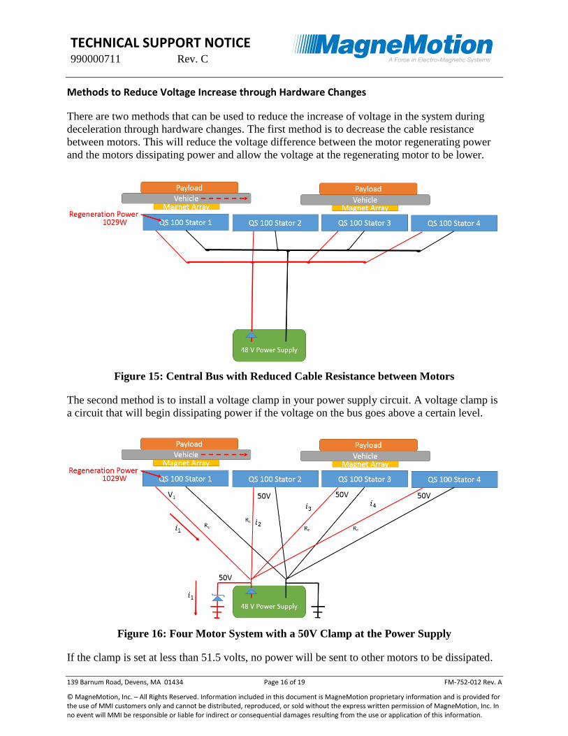
Methods to Reduce Voltage Increase through Hardware Changes
There are two methods that can be used to reduce the increase of voltage in the system during
deceleration through hardware changes. The first method is to decrease the cable resistance
between motors. This will reduce the voltage difference between the motor regenerating power
and the motors dissipating power and allow the voltage at the regenerating motor to be lower.
Figure 15: Central Bus with Reduced Cable Resistance between Motors
The second method is to install a voltage clamp in your power supply circuit. A voltage clamp is
a circuit that will begin dissipating power if the voltage on the bus goes above a certain level.
Figure 16: Four Motor System with a 50V Clamp at the Power Supply
If the clamp is set at less than 51.5 volts, no power will be sent to other motors to be dissipated.

TECHNICAL SUPPORT NOTICE 990000711 Rev. C
139 Barnum Road, Devens, MA 01434 Page 17 of 19 FM-752-012 Rev. A
© MagneMotion, Inc. – All Rights Reserved. Information included in this document is MagneMotion proprietary information and is provided for the use of MMI customers only and cannot be distributed, reproduced, or sold without the express written permission of MagneMotion, Inc. In no event will MMI be responsible or liable for indirect or consequential damages resulting from the use or application of this information.
0 = 𝑖2 = 𝑖3 = 𝑖4
The voltage at the regenerating motor will equal to the clamp voltage plus the voltage drop in the
cable leading to the clamp. This can be represented as a combination of the Power Law and
Ohm’s Law.
𝑉1 =𝑃1
𝑖1= 50𝑉 + 𝑖1𝑅𝑐
This method will have no effect on the under voltage case directly, but may allow the power
supply to be set to a higher voltage to compensate for voltage drop in longer cables without
risking exceeding the high voltage limit of the motor.
If a clamp voltage below 51.5V is selected as shown here, ensure that the circuit is rated for the
total regenerated power. This is because below 51.5V, no power will be dissipated by the other
motors.
Summary
In larger systems, the sizing of the power cabling can have a significant effect on system
performance. Incorrectly sized cables can lead to:
• Soft Start Not Complete Faults resulting in the motor losing propulsion power
• Over Voltage Faults results in the motor shutting down
• Damage to motors
• Soft start resistor failure due to repeated under voltage
• Protection resistor failure due to repeated over voltage
• Reduced motor life due to increased component stress
• Possible uncontrolled vehicle motion due to loss of propulsion or control power leading
to collisions
The electrical design of the power system for the QuickStick motors is the responsibility of the
system integrator. MagneMotion strongly recommends that all power systems be reviewed by an
electrical engineer prior to installation. The examples in this document are simplifications of an
actual electrical system and apply only to the specific circumstances described.

TECHNICAL SUPPORT NOTICE 990000711 Rev. C
139 Barnum Road, Devens, MA 01434 Page 18 of 19 FM-752-012 Rev. A
© MagneMotion, Inc. – All Rights Reserved. Information included in this document is MagneMotion proprietary information and is provided for the use of MMI customers only and cannot be distributed, reproduced, or sold without the express written permission of MagneMotion, Inc. In no event will MMI be responsible or liable for indirect or consequential damages resulting from the use or application of this information.
Appendix
Appendix A: Power Dissipated per Block
Figure 17: Power Dissipated per Block
0
5
10
15
20
25
30
35
40
45
50
50.5 51.5 52.5 53.5 54.5
Po
wer
/Blo
ck
+48 V Internal Bus Voltage
Power Dissipated/block (W) vs. +48 V internal propulsion bus voltage (V)

TECHNICAL SUPPORT NOTICE 990000711 Rev. C
139 Barnum Road, Devens, MA 01434 Page 19 of 19 FM-752-012 Rev. A
© MagneMotion, Inc. – All Rights Reserved. Information included in this document is MagneMotion proprietary information and is provided for the use of MMI customers only and cannot be distributed, reproduced, or sold without the express written permission of MagneMotion, Inc. In no event will MMI be responsible or liable for indirect or consequential damages resulting from the use or application of this information.
For any questions related to the content of this document, please contact MagneMotion Customer
Support.
Phone: +1 978-757-9102 (9am – 5pm EST)
Email: [email protected]
More Information
MagneMotion Website: www.magnemotion.com
Questions & Comments: www.magnemotion.com/about-magnemotion/contact.cfm
Revision History
Rev. Change Description
A Initial release
B Fixes Formatting Errors
C Updated for new software versions. Removed background equations section.