application note: aph010 - decawave ltd example, transmissions from a transmitter configured for...
TRANSCRIPT
© DecaWave 2014 This document is confidential and contains information which is proprietary to DecaWave Limited. No reproduction is permitted without prior express written permission of the author
APPLICATION NOTE: APH010
APH010 DW1000 INTER-CHANNEL INTERFERENCE
How transmissions on one DW1000 channel can affect other channels and how to minimize that effect
2014
Version 0.2
This document is subject to change without notice

APH010 DW1000 INTER-CHANNEL INTERFERENCE
© DecaWave 2014 This document is confidential and contains information which is proprietary to DecaWave Limited. No reproduction is permitted without prior express written permission of the author
Page 2 of 25
TABLE OF CONTENTS
1 INTRODUCTION ..................................................................................................................... 4
2 SUMMARY RESULTS AND CONCLUSIONS................................................................................ 5
2.1 INTRODUCTION ............................................................................................................................. 5 2.2 METHODOLOGY ............................................................................................................................ 5 2.3 TRANSMISSION / RECEPTION ON THE SAME CHANNEL .......................................................................... 5 2.4 TRANSMISSION / RECEPTION ON DIFFERENT CHANNELS ....................................................................... 5 2.5 CONCLUSIONS & GUIDELINES .......................................................................................................... 7
3 INTER CHANNEL INTERFERENCE IN THE DW1000 .................................................................... 8
3.1 OVERVIEW ................................................................................................................................... 8 3.2 RF SIGNAL INTERFERENCE BETWEEN CHANNELS .................................................................................. 8 3.3 RESULTING INTERFERENCE .............................................................................................................. 9
4 EFFECT OF USING DIFFERENT PRF AND PREAMBLE CODES ON THE SAME CHANNEL FOR TRANSMIT & RECEIVE................................................................................................................. 14
4.1 INTRODUCTION ........................................................................................................................... 14 4.2 DIFFERENT VALUES OF PRF AND PREAMBLE CODE ............................................................................ 14 4.3 SAME PRF BUT DIFFERENT PREAMBLE CODES .................................................................................. 14
5 INTERFERENCE BETWEEN DIFFERENT CHANNELS WHEN USING DIFFERENT PRF AND PREAMBLE CODES ....................................................................................................................................... 17
5.1 INTRODUCTION ........................................................................................................................... 17 5.2 DIFFERENT PRF AND PREAMBLE CODE SETTINGS .............................................................................. 17 5.3 SAME PRF BUT DIFFERENT PREAMBLE CODES .................................................................................. 17
6 CONCLUSIONS AND GUIDELINES FOR CHANNEL CONFIGURATION ........................................ 21
6.1 CONCLUSION .............................................................................................................................. 21 6.2 GUIDELINES TO MINIMIZE THIS INTERFERENCE .................................................................................. 21
7 APPENDIX 1: TEST METHODOLOGY ...................................................................................... 23
7.1 TEST SETUP ................................................................................................................................ 23 7.1.1 Initial Calibration of the test rig ...................................................................................... 23 7.1.2 Actual Interference testing .............................................................................................. 23
LIST OF TABLES
TABLE 1: SUMMARY OF INTER-CHANNEL INTERFERENCE USING THE SAME PRF AND PREAMBLE CODE. ....................... 6 TABLE 2: SUMMARY OF INTER-CHANNEL INTERFERENCE USING DIFFERENT PREAMBLE CODES AT 64MHZ PRF ............ 7 TABLE 3: EFFECT OF PRF / PREAMBLE CODE ON CHANNEL 1 ............................................................................ 15 TABLE 4: EFFECT OF PRF / PREAMBLE CODE ON CHANNEL 2 ............................................................................ 15 TABLE 5: EFFECT OF PRF / PREAMBLE CODE ON CHANNEL 3 ............................................................................ 16 TABLE 6: EFFECT OF PRF / PREAMBLE CODE ON CHANNEL 5 ............................................................................ 16 TABLE 7: SUMMARY OF INTER-CHANNEL INTERFERENCE USING THE SAME PRF / PREAMBLE CODE ........................... 17 TABLE 8: EFFECT OF PREAMBLE CODE ON INTERFERENCE FROM CHANNEL 1 TO CHANNEL 2 ................................... 18 TABLE 9: EFFECT OF PREAMBLE CODE ON INTERFERENCE FROM CHANNEL 1 TO CHANNEL 3 ................................... 18 TABLE 10: EFFECT OF PREAMBLE CODE ON INTERFERENCE FROM CHANNEL 2 TO CHANNEL 1 ................................. 19 TABLE 11: EFFECT OF PREAMBLE CODE ON INTERFERENCE FROM CHANNEL 2 TO CHANNEL 3 ................................. 19 TABLE 12: EFFECT OF PREAMBLE CODE ON INTERFERENCE FROM CHANNEL 3 TO CHANNEL 2 ................................. 20

APH010 DW1000 INTER-CHANNEL INTERFERENCE
© DecaWave 2014 This document is confidential and contains information which is proprietary to DecaWave Limited. No reproduction is permitted without prior express written permission of the author
Page 3 of 25
TABLE 13: SUMMARY OF INTER-CHANNEL INTERFERENCE USING DIFFERENT PREAMBLE CODES AT 64MHZ PRF ........ 22 TABLE 14: TEST EQUIPMENT LOSS FOR VARIOUS CHANNEL AND PRF SETTINGS ..................................................... 23
LIST OF FIGURES FIGURE 1: IEEE802.15.4-2011 PPDU STRUCTURE ........................................................................................ 4 FIGURE 2: TX CHANNEL 1 / RX CHANNEL 2 ...................................................................................................... 6 FIGURE 3: TX CHANNEL 1 / RX CHANNEL 5 ...................................................................................................... 6 FIGURE 4: EXAMPLE SIMULATED PSD FROM A TRANSMITTER CONFIGURED TO TRANSMIT ON CHANNEL 2 AT 4 GHZ..... 9 FIGURE 5: TX / RX CHANNEL 1 .................................................................................................................... 10 FIGURE 6: TX / RX CHANNEL 2 .................................................................................................................... 10 FIGURE 7: TX / RX CHANNEL 3 .................................................................................................................... 10 FIGURE 8: TX / RX CHANNEL 5 .................................................................................................................... 10 FIGURE 9: TX CHANNEL 1 / RX CHANNEL 2 .................................................................................................... 11 FIGURE 10: TX CHANNEL 1 / RX CHANNEL 3 .................................................................................................. 11 FIGURE 11: TX CHANNEL 1 / RX CHANNEL 5 .................................................................................................. 11 FIGURE 12: TX CHANNEL 2 / RX CHANNEL 1 .................................................................................................. 11 FIGURE 13: TX CHANNEL 2 / RX CHANNEL 3 .................................................................................................. 12 FIGURE 14: TX CHANNEL 2 / RX CHANNEL 5 .................................................................................................. 12 FIGURE 15: TX CHANNEL 3 / RX CHANNEL 1 .................................................................................................. 12 FIGURE 16: TX CHANNEL 3 / RX CHANNEL 2 .................................................................................................. 12 FIGURE 17: TX CHANNEL 3 / RX CHANNEL 5 .................................................................................................. 13 FIGURE 18: TX CHANNEL 5 / RX CHANNEL 1 .................................................................................................. 13 FIGURE 19: TX CHANNEL 5 / RX CHANNEL 2 .................................................................................................. 13 FIGURE 20: TX CHANNEL 5 / RX CHANNEL 3 .................................................................................................. 13

APH010 DW1000 INTER-CHANNEL INTERFERENCE
© DecaWave 2014 This document is confidential and contains information which is proprietary to DecaWave Limited. No reproduction is permitted without prior express written permission of the author
Page 4 of 25
1 INTRODUCTION
The DW10000 can be configured to operate on one of 6 RF channels with centre frequencies from 3.5 GHz to 6.5 GHz. It uses the modulation scheme and messaging format as defined by the IEEE802.15.4-2011 UWB standard shown in Figure 1 below.
Figure 1: IEEE802.15.4-2011 PPDU Structure
Header and payload portions of the message are transmitted using very narrow pulses repeated at the Pulse Repetition Frequency (PRF) which is slightly different for header and payload portions of the message but nominally can be 16 or 64 MHz. The preamble sequence portion of the message is transmitted as one of a number of selectable codes. Restrictions are imposed on the selection of these codes depending on the channel being used. Preamble sequences are selected for use in the UWB PHY due to their perfect periodic autocorrelation properties. The choice of codes that may be used for each channel is restricted to ensure that codes with the lowest cross-correlation are used in the same UWB PHY channel. Thus, different devices can communicate on the same physical channel each using different preamble codes whilst interfering as little as possible. This note examines how transmissions on one particular channel can cause interference with: -
Receivers on the same channel configured for different values of PRF and / or preamble code
Receivers on different channels configured for the same or different PRF and / or preamble codes
Guidelines are presented for the selection of PRF and preamble codes to minimize such interference.
Preamble SequenceStart Frame
Delimiter
(SFD)PHR MAC Protocol Data Unit (MPDU)
PHY Protocol Data Unit (PPDU)
16,64,1024 or 4096 Preambles
8 or 64
Symbols 21 bits 8*Frame Length + Reed-Solomon Encoding bits
Synchronisation Header (SHR) PHY
Header
(PHR)
PHY Service Data Unit (PSDU)
APH010 DW1000 INTER-CHANNEL INTERFERENCE
© DecaWave 2014 This document is confidential and contains information which is proprietary to DecaWave Limited. No reproduction is permitted without prior express written permission of the author
Page 5 of 25
2 SUMMARY RESULTS AND CONCLUSIONS
2.1 Introduction
This section presents summary results from the various investigations detailed later in this note as well as conclusions and guidelines to minimize inter and intra-channel interference.
2.2 Methodology
The methodology used in testing for interference between a transmitter and a victim receiver was to introduce and increase the level of attenuation between the transmitter and the victim receiver until the victim receiver was unaffected by the transmissions. This level of attenuation was converted to an equivalent distance assuming free space operation. This equivalent distance is denoted the “pickup radius”. Where the pickup radius proved to be unacceptably large (>2 m) further investigation was carried out to determine whether particular combinations of preamble codes / PRF could be used to extend it and with what effect.
2.3 Transmission / Reception on the same channel
Using different PRF configurations on the same channel ensures that no interference will occur. So, for example, transmissions from a transmitter configured for channel 2, 16 MHz PRF will not be received by a receiver configured for channel 2, 64 MHz PRF. With the same PRF configuration but different preamble codes selected then interference may occur because while the preamble codes have a low cross-correlation they are not orthogonal. The summary of these results is as follows: -
Pickup Radius (m) for this channel at this PRF for worst case
combination of preamble codes
PRF CH1 CH2 CH3 CH5
16 MHz 72 80 76 57
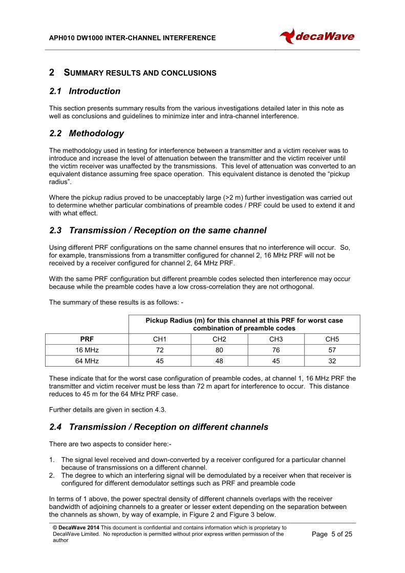
64 MHz 45 48 45 32
These indicate that for the worst case configuration of preamble codes, at channel 1, 16 MHz PRF the transmitter and victim receiver must be less than 72 m apart for interference to occur. This distance reduces to 45 m for the 64 MHz PRF case. Further details are given in section 4.3.
2.4 Transmission / Reception on different channels
There are two aspects to consider here:- 1. The signal level received and down-converted by a receiver configured for a particular channel
because of transmissions on a different channel. 2. The degree to which an interfering signal will be demodulated by a receiver when that receiver is
configured for different demodulator settings such as PRF and preamble code In terms of 1 above, the power spectral density of different channels overlaps with the receiver bandwidth of adjoining channels to a greater or lesser extent depending on the separation between the channels as shown, by way of example, in Figure 2 and Figure 3 below.

APH010 DW1000 INTER-CHANNEL INTERFERENCE
© DecaWave 2014 This document is confidential and contains information which is proprietary to DecaWave Limited. No reproduction is permitted without prior express written permission of the author
Page 6 of 25
4GHz 5GHz 6GHz 7GHz3GHz2GHz1GHz
-90dBm
-80dBm
-70dBm
-60dBm
-50dBm
-40dBm
-30dBm
RX CH2
TX CH1
Figure 2: Tx Channel 1 / Rx Channel 2
4GHz 5GHz 6GHz 7GHz3GHz2GHz1GHz
-90dBm
-80dBm
-70dBm
-60dBm
-50dBm
-40dBm
-30dBm
RX CH5
TX CH1
Figure 3: Tx Channel 1 / Rx Channel 5
This is discussed and illustrated further in section 3.2. With respect to point 2 above, the table below shows the situation when the transmitting channel and the victim channel are configured for the same PRF and preamble code.
Table 1: Summary of inter-channel interference using the same PRF and preamble code.
Legend Explanation
Desired Desired operation; e.g. transmit on channel 1, receive on channel 1
No interference
< x.y m Interference will occur when range between transmitter and receiver is less than x.y m
Pickup radius is large enough to warrant further investigation
RECEIVE on this channel
TRANSMIT
on this channel CH1 CH2 CH3 CH4 CH5 CH7
CH1 Desired <56 m <3.5 m 1.3 m
CH2 <60 m Desired <85 m Desired 1.1 m
CH3 1.59 m <40 m Desired <1 m
CH5 0.14 m 1.2 m 0.05 m Desired Desired
These results are discussed in more detail in section 5 Analysing the situations highlighted in red above and adjusting preamble codes to minimize the

APH010 DW1000 INTER-CHANNEL INTERFERENCE
© DecaWave 2014 This document is confidential and contains information which is proprietary to DecaWave Limited. No reproduction is permitted without prior express written permission of the author
Page 7 of 25
pickup radius yields the following analysis.
Table 2: Summary of inter-channel interference using different preamble codes at 64MHz PRF
Legend Explanation
Desired Desired operation; e.g. transmit on channel 1, receive on channel 1
No interference
< x.y m Interference will occur when range between Transmitter and Receiver is less than x.y m
RECEIVE on
CH1 CH2 CH3 CH4 CH5 CH7
TR
AN
SM
IT
on
CH1 Desired < 8 m < 0.7 m < 1 m
CH2 < 9.7 m Desired < 11 m Desired < 1 m
CH3 < 1 m < 7 m Desired <1 m
CH5 < 1 m Desired Desired
This shows that the appropriate selection of preamble code can significantly reduce the pickup radius.
2.5 Conclusions & Guidelines
Inter-channel interference does occur in UWB systems. This interference can be minimized by the appropriate selection of channels and channel configurations. There is a two stage approach here: -
1. Minimize the level of the RF signal received by the victim receiver.
Keep channels well separated.
Reduce the side lobes in the power spectrum of the transmitter by modifying the transmitter configuration.
It is possible to modify the power spectrum of the transmitter by using a band-pass filter between the DW1000 and the antenna centred on the channel centre-frequency of interest and with a steep cut-off at the band edges.
Using an antenna optimized for a particular channel will help to reduce transmitted power in adjacent channels (and reception of interfering signals from outside the channel of interest)
2. Minimize the extent to which the transmitted frame is demodulated / decoded by the victim
receiver.
With different settings for PRF and Preamble code in the interfering transmitter and victim
receiver no unwanted data is received
With the interfering transmitter and victim receiver configured for the same PRF but different preamble codes, signals from the interfering channel may be received on the victim channel but only when the distance between the interfering transmitter and the victim receiver is below a
certain limit as per Table 1Table 2.
64 MHz PRF is more resistant to inter-channel interference than 16 MHz PRF From Table 2

APH010 DW1000 INTER-CHANNEL INTERFERENCE
© DecaWave 2014 This document is confidential and contains information which is proprietary to DecaWave Limited. No reproduction is permitted without prior express written permission of the author
Page 8 of 25
Table 13, with all channels configured for 64 MHz PRF, by choosing appropriate preamble codes the inter-channel interference can be reduced to the point where the interfering transmitter must be within approximately 1 m of the victim receiver for inter-channel interference to become a problem.
At 16MHz PRF this distance goes up to approximately 2.2 m
These conclusions & guidelines are discussed more fully in section 6.

APH010 DW1000 INTER-CHANNEL INTERFERENCE
© DecaWave 2014 This document is confidential and contains information which is proprietary to DecaWave Limited. No reproduction is permitted without prior express written permission of the author
Page 9 of 25
3 INTER CHANNEL INTERFERENCE IN THE DW1000
3.1 Overview
There are two aspects to inter-channel interference: - 3. The signal level received and down-converted by a receiver configured for a particular channel
because of transmissions on a different channel. This phenomenon can be examined and understood by looking at the transmitter power spectral density and understanding the frequency response of the receiver.
4. The degree to which an interfering signal will be demodulated by a receiver when that receiver is configured for different demodulator settings such as PRF and preamble code
3.2 RF signal interference between channels
Looking at the power spectral density (PSD) of the transmit signal we can see that the main transmitted energy is in the wanted channel around the centre frequency of that channel. However, the PSD of the transmitted impulse has side lobes which contain significant energy in the frequency ranges of other valid channels. These side-lobes are such that those on the right hand, higher frequency, side are stronger than those on the left hand, or lower frequency, side. This means that lower channels interfere more strongly with higher frequency ones than vice versa. Note that it is possible to configure the DW1000 transmitter to generate side lobes of lower energy, but such a configuration will consume more current. The transmitter configurations used for the measurements presented in this document are the optimal settings as given in the DW1000 User Manual. The DW1000 wideband receiver is very sensitive and when it is configured to receive on a particular channel it is also capable of receiving these low level side-lobes as a result of transmissions on a different channel which will then be down-converted to baseband in the receive strip. The PSD of the side-lobes is generally attenuated by 30 dB or more compared to the transmit PSD main lobe.
APH010 DW1000 INTER-CHANNEL INTERFERENCE
© DecaWave 2014 This document is confidential and contains information which is proprietary to DecaWave Limited. No reproduction is permitted without prior express written permission of the author
Page 10 of 25
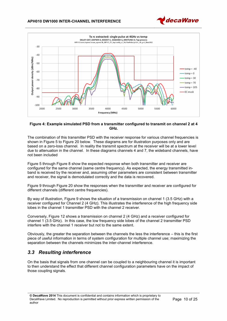
Figure 4: Example simulated PSD from a transmitter configured to transmit on channel 2 at 4 GHz.
The combination of this transmitter PSD with the receiver response for various channel frequencies is shown in Figure 5 to Figure 20 below. These diagrams are for illustration purposes only and are based on a zero-loss channel. In reality the transmit spectrum at the receiver will be at a lower level due to attenuation in the channel. In these diagrams channels 4 and 7, the wideband channels, have not been included Figure 5 through Figure 8 show the expected response when both transmitter and receiver are configured for the same channel (same centre frequency). As expected, the energy transmitted in-band is received by the receiver and, assuming other parameters are consistent between transmitter and receiver, the signal is demodulated correctly and the data is recovered. Figure 9 through Figure 20 show the responses when the transmitter and receiver are configured for different channels (different centre frequencies). By way of illustration, Figure 9 shows the situation of a transmission on channel 1 (3.5 GHz) with a receiver configured for Channel 2 (4 GHz). This illustrates the interference of the high frequency side lobes in the channel 1 transmitter PSD with the channel 2 receiver. Conversely, Figure 12 shows a transmission on channel 2 (4 GHz) and a receiver configured for channel 1 (3.5 GHz). In this case, the low frequency side lobes of the channel 2 transmitter PSD interfere with the channel 1 receiver but not to the same extent. Obviously, the greater the separation between the channels the less the interference – this is the first piece of useful information in terms of system configuration for multiple channel use; maximizing the separation between the channels minimizes the inter-channel interference.
3.3 Resulting interference
On the basis that signals from one channel can be coupled to a neighbouring channel it is important to then understand the effect that different channel configuration parameters have on the impact of those coupling signals.

APH010 DW1000 INTER-CHANNEL INTERFERENCE
© DecaWave 2013 This document is confidential and contains information which is proprietary to DecaWave Limited. No reproduction is permitted without prior express written permission of the author Page 11 of 25
4GHz 5GHz 6GHz 7GHz3GHz2GHz1GHz
-90dBm
-80dBm
-70dBm
-60dBm
-50dBm
-40dBm
-30dBm
RX CH1
TX CH1
Figure 5: Tx / Rx Channel 1
4GHz 5GHz 6GHz 7GHz3GHz2GHz1GHz
-90dBm
-80dBm
-70dBm
-60dBm
-50dBm
-40dBm
-30dBm
RX CH2
TX CH2
Figure 6: Tx / Rx Channel 2
4GHz 5GHz 6GHz 7GHz3GHz2GHz1GHz
-90dBm
-80dBm
-70dBm
-60dBm
-50dBm
-40dBm
-30dBm
RX CH3
TX CH3
Figure 7: Tx / Rx Channel 3
4GHz 5GHz 6GHz 7GHz3GHz2GHz1GHz
-90dBm
-80dBm
-70dBm
-60dBm
-50dBm
-40dBm
-30dBm
RX CH5
TX CH5
8GHz
Figure 8: Tx / Rx Channel 5

APH010 DW1000 INTER-CHANNEL INTERFERENCE
© DecaWave 2013 This document is confidential and contains information which is proprietary to DecaWave Limited. No reproduction is permitted without prior express written permission of the author Page 12 of 25
4GHz 5GHz 6GHz 7GHz3GHz2GHz1GHz
-90dBm
-80dBm
-70dBm
-60dBm
-50dBm
-40dBm
-30dBm
RX CH2
TX CH1
Figure 9: Tx Channel 1 / Rx Channel 2
4GHz 5GHz 6GHz 7GHz3GHz2GHz1GHz
-90dBm
-80dBm
-70dBm
-60dBm
-50dBm
-40dBm
-30dBm
RX CH3
TX CH1
Figure 10: Tx Channel 1 / Rx Channel 3
4GHz 5GHz 6GHz 7GHz3GHz2GHz1GHz
-90dBm
-80dBm
-70dBm
-60dBm
-50dBm
-40dBm
-30dBm
RX CH5
TX CH1
Figure 11: Tx Channel 1 / Rx Channel 5
4GHz 5GHz 6GHz 7GHz3GHz2GHz1GHz
-90dBm
-80dBm
-70dBm
-60dBm
-50dBm
-40dBm
-30dBm
RX CH1
TX CH2
Figure 12: Tx Channel 2 / Rx Channel 1

APH010 DW1000 INTER-CHANNEL INTERFERENCE
© DecaWave 2013 This document is confidential and contains information which is proprietary to DecaWave Limited. No reproduction is permitted without prior express written permission of the author Page 13 of 25
4GHz 5GHz 6GHz 7GHz3GHz2GHz1GHz
-90dBm
-80dBm
-70dBm
-60dBm
-50dBm
-40dBm
-30dBm
TX CH2
RX CH3
Figure 13: Tx Channel 2 / Rx Channel 3
4GHz 5GHz 6GHz 7GHz3GHz2GHz1GHz
-90dBm
-80dBm
-70dBm
-60dBm
-50dBm
-40dBm
-30dBm
RX CH5
TX CH2
Figure 14: Tx Channel 2 / Rx Channel 5
4GHz 5GHz 6GHz 7GHz3GHz2GHz1GHz
-90dBm
-80dBm
-70dBm
-60dBm
-50dBm
-40dBm
-30dBm
RX CH1
TX CH3
Figure 15: Tx Channel 3 / Rx Channel 1
4GHz 5GHz 6GHz 7GHz3GHz2GHz1GHz
-90dBm
-80dBm
-70dBm
-60dBm
-50dBm
-40dBm
-30dBm
RX CH2
TX CH3
Figure 16: Tx Channel 3 / Rx Channel 2

APH010 DW1000 INTER-CHANNEL INTERFERENCE
© DecaWave 2013 This document is confidential and contains information which is proprietary to DecaWave Limited. No reproduction is permitted without prior express written permission of the author Page 14 of 25
4GHz 5GHz 6GHz 7GHz3GHz2GHz1GHz
-90dBm
-80dBm
-70dBm
-60dBm
-50dBm
-40dBm
-30dBm
RX CH5
TX CH3
Figure 17: Tx Channel 3 / Rx Channel 5
4GHz 5GHz 6GHz 7GHz3GHz2GHz1GHz
-90dBm
-80dBm
-70dBm
-60dBm
-50dBm
-40dBm
-30dBm
RX CH2
TX CH5
8GHz
Figure 18: Tx Channel 5 / Rx Channel 1
4GHz 5GHz 6GHz 7GHz3GHz2GHz1GHz
-90dBm
-80dBm
-70dBm
-60dBm
-50dBm
-40dBm
-30dBm
RX CH2
TX CH5
8GHz
Figure 19: Tx Channel 5 / Rx Channel 2
4GHz 5GHz 6GHz 7GHz3GHz2GHz1GHz
-90dBm
-80dBm
-70dBm
-60dBm
-50dBm
-40dBm
-30dBm
RX CH3
TX CH5
8GHz
Figure 20: Tx Channel 5 / Rx Channel 3

APH010 DW1000 INTER-CHANNEL INTERFERENCE
© DecaWave 2014 This document is confidential and contains information which is proprietary to DecaWave Limited. No reproduction is permitted without prior express written permission of the author
Page 15 of 25
4 EFFECT OF USING DIFFERENT PRF AND PREAMBLE CODES ON THE SAME
CHANNEL FOR TRANSMIT & RECEIVE
4.1 Introduction
In order to analyse the level of inter-channel interference suggested in the preceding plots it is first useful to examine the effects of using different values of PRF and preamble code when the transmitter and receiver are configured for the same channel. The test methodology employed here is discussed in Appendix 1 but, in summary, a transmitter and receiver are connected via a wired connection with in-line attenuators. These attenuators are adjusted to simulate distance between the transmitter and receiver. For each configuration the attenuation is adjusted until the interfering signal is no longer received. The attenuation setting is converted to distance (knowing the attenuation of radio signals in free-space at the frequency of transmission) and the resulting “interference radius” or “pickup radius” i.e. the distance beyond which it can be guaranteed that the transmission will not interfere is recorded in the tables below.
4.2 Different values of PRF and Preamble code
With the transmitter and receiver configured with different values of PRF, no signal is received irrespective of preamble code.
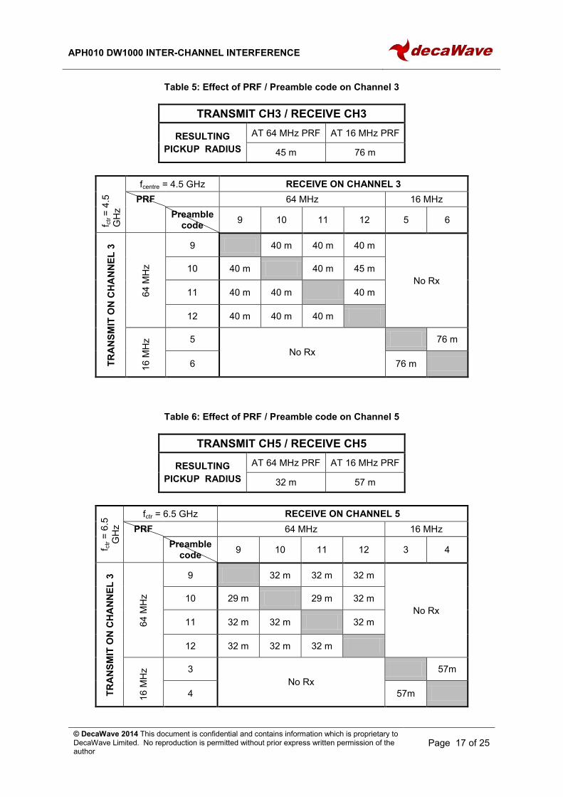
4.3 Same PRF but different Preamble codes
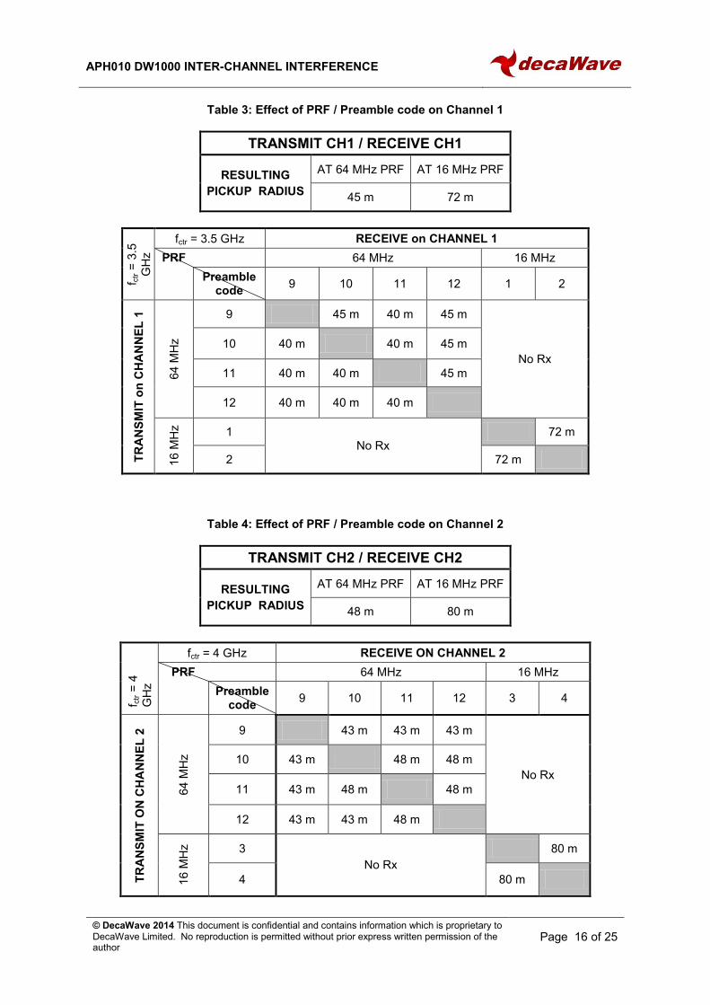
With the transmitter and receiver configured with the same PRF but different preamble codes some interference may result because while the preamble codes have a low cross-correlation they are not orthogonal. The results of these various combinations are shown below in Table 3 through Table 6. In these tables the following legend is used: -
Legend Explanation
Desired Desired operation; e.g. transmit on channel 1, receive on channel 1
x m Interference will occur when range between transmitter and receiver is less than x m
APH010 DW1000 INTER-CHANNEL INTERFERENCE
© DecaWave 2014 This document is confidential and contains information which is proprietary to DecaWave Limited. No reproduction is permitted without prior express written permission of the author
Page 16 of 25
Table 3: Effect of PRF / Preamble code on Channel 1
TRANSMIT CH1 / RECEIVE CH1
RESULTING
PICKUP RADIUS
AT 64 MHz PRF AT 16 MHz PRF
45 m 72 m
f ctr =
3.5
GH
z
fctr = 3.5 GHz RECEIVE on CHANNEL 1
PRF 64 MHz 16 MHz
Preamble
code 9 10 11 12 1 2
TR
AN
SM
IT o
n C
HA
NN
EL
1
64 M
Hz
9 45 m 40 m 45 m
No Rx
10 40 m 40 m 45 m
11 40 m 40 m 45 m
12 40 m 40 m 40 m
16 M
Hz
1 No Rx
72 m
2 72 m
Table 4: Effect of PRF / Preamble code on Channel 2
TRANSMIT CH2 / RECEIVE CH2
RESULTING
PICKUP RADIUS
AT 64 MHz PRF AT 16 MHz PRF
48 m 80 m
f ctr =
4
GH
z
fctr = 4 GHz RECEIVE ON CHANNEL 2
PRF 64 MHz 16 MHz
Preamble
code 9 10 11 12 3 4
TR
AN
SM
IT O
N C
HA
NN
EL
2
64 M
Hz
9 43 m 43 m 43 m
No Rx
10 43 m 48 m 48 m
11 43 m 48 m 48 m
12 43 m 43 m 48 m
16 M
Hz
3
No Rx
80 m
4 80 m
APH010 DW1000 INTER-CHANNEL INTERFERENCE
© DecaWave 2014 This document is confidential and contains information which is proprietary to DecaWave Limited. No reproduction is permitted without prior express written permission of the author
Page 17 of 25
Table 5: Effect of PRF / Preamble code on Channel 3
TRANSMIT CH3 / RECEIVE CH3
RESULTING
PICKUP RADIUS
AT 64 MHz PRF AT 16 MHz PRF
45 m 76 m
f ctr
= 4
.5
GH
z
fcentre = 4.5 GHz RECEIVE ON CHANNEL 3
PRF 64 MHz 16 MHz
Preamble
code 9 10 11 12 5 6
TR
AN
SM
IT O
N C
HA
NN
EL
3
64 M
Hz
9 40 m 40 m 40 m
No Rx
10 40 m 40 m 45 m
11 40 m 40 m 40 m
12 40 m 40 m 40 m
16 M
Hz 5
No Rx
76 m
6 76 m
Table 6: Effect of PRF / Preamble code on Channel 5
TRANSMIT CH5 / RECEIVE CH5
RESULTING
PICKUP RADIUS
AT 64 MHz PRF AT 16 MHz PRF
32 m 57 m
f ctr =
6.5
GH
z
fctr = 6.5 GHz RECEIVE ON CHANNEL 5
PRF 64 MHz 16 MHz
Preamble
code 9 10 11 12 3 4
TR
AN
SM
IT O
N C
HA
NN
EL
3
64 M
Hz
9 32 m 32 m 32 m
No Rx
10 29 m 29 m 32 m
11 32 m 32 m 32 m
12 32 m 32 m 32 m
16 M
Hz 3
No Rx
57m
4 57m

APH010 DW1000 INTER-CHANNEL INTERFERENCE
© DecaWave 2014 This document is confidential and contains information which is proprietary to DecaWave Limited. No reproduction is permitted without prior express written permission of the author
Page 18 of 25
5 INTERFERENCE BETWEEN DIFFERENT CHANNELS WHEN USING DIFFERENT
PRF AND PREAMBLE CODES
5.1 Introduction
To begin with, a summary of the inter-channel interference and its pickup radius when using the same PRF and preamble code is shown in Table 7.
Table 7: Summary of inter-channel interference using the same PRF / preamble code
Legend Explanation
Desired Desired operation; e.g. transmit on channel 1, receive on channel 1
No interference
< x.y m Interference will occur when range between transmitter and receiver is less than x.y m
Pickup radius is large enough to warrant further investigation
RECEIVE on this channel
TRANSMIT
on this channel CH1 CH2 CH3 CH4 CH5 CH7
CH1 Desired <56 m <3.5 m 1.3 m
CH2 <60 m Desired <85 m Desired 1.1 m
CH3 1.59 m <40 m Desired <1 m
CH5 0.14 m 1.2 m 0.05 m Desired Desired
For those cases where the pickup radius is seen to be greater than 2 m (in red in Table 7), the inter-channel interference is tested further to determine what combinations of PRF and preamble codes may be used to minimize it.
5.2 Different PRF and Preamble code settings
Using different PRFs and different Preamble codes in both the transmitter and receiver, there is no received signal.
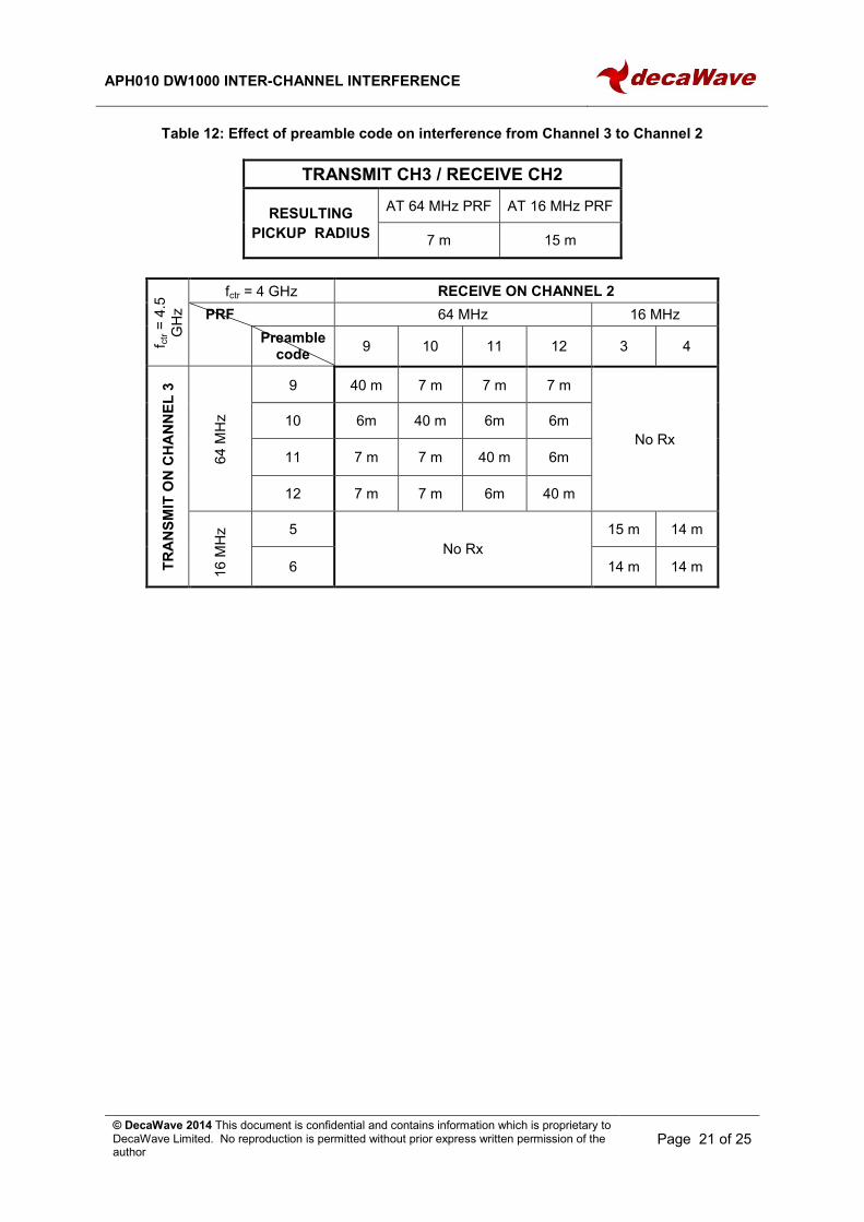
5.3 Same PRF but different Preamble codes
Using the same PRF but different Preamble codes, the test results are as shown in the tables below: -

APH010 DW1000 INTER-CHANNEL INTERFERENCE
© DecaWave 2014 This document is confidential and contains information which is proprietary to DecaWave Limited. No reproduction is permitted without prior express written permission of the author
Page 19 of 25
Table 8: Effect of Preamble code on interference from Channel 1 to Channel 2
TRANSMIT CH1 / RECEIVE CH2
RESULTING
PICKUP RADIUS
AT 64 MHz PRF AT 16 MHz PRF
8 m 16 m
f ctr =
3.5
GH
z
fcentre = 4 GHz RECEIVE ON CHANNEL 2
PRF 64 MHz 16 MHz
Preamble
code 9 10 11 12 3 4
TR
AN
SM
IT O
N C
HA
NN
EL
1
64M
Hz
9 56 m 8 m 8 m 8 m
No Rx
10 8 m 56 m 8 m 8 m
11 8 m 8 m 56 m 8 m
12 8 m 8 m 7 m 56 m
16M
Hz 1
No Rx
14 m 14 m
2 16 m 16 m
Table 9: Effect of Preamble code on interference from Channel 1 to Channel 3
TRANSMIT CH 1 / RECEIVE CH 3
RESULTING
PICKUP RADIUS
AT 64 MHz PRF AT 16 MHz PRF
0.7 m 2.2 m
f ctr =
3.5
GH
z
fcentre = 4.5 GHz RECEIVE ON CHANNEL 3
PRF 64 MHz 16 MHz
Preamble
code 9 10 11 12 5 6
TR
AN
SM
IT O
N C
HA
NN
EL
1
64M
Hz
9 3.5 m 0.7m 0.7 m 0.7 m
No Rx
10 0.7 m 3.5 m 0.7 m 0.7 m
11 0.7 m 0.7 m 3.5 m 0.7 m
12 0.6 m 0.7 m 0.7 m 3.5 m
16M
Hz 1
No Rx
2.2 m 2.2 m
2 2.2 m 2.2 m

APH010 DW1000 INTER-CHANNEL INTERFERENCE
© DecaWave 2014 This document is confidential and contains information which is proprietary to DecaWave Limited. No reproduction is permitted without prior express written permission of the author
Page 20 of 25
Table 10: Effect of preamble code on interference from Channel 2 to Channel 1
TRANSMIT CH2 / RECEIVE CH1
RESULTING
PICKUP RADIUS
AT 64 MHz PRF AT 16 MHz PRF
9.7 m 20 m
f ctr =
4
GH
z
fctr = 3.5 GHz RECEIVE ON CHANNEL 1
PRF 64 MHz 16 MHz
Preamble
code 9 10 11 12 1 2
TR
AN
SM
IT O
N C
HA
NN
EL
2
64 M
Hz
9 60 m 9 m 9 m 9.7 m
No Rx
10 9m 60 m 9 m 9.7 m
11 9 m 9 m 60 m 9.7 m
12 9 m 9.7 m 9 m 60 m
16 M
Hz 3
No Rx
18 m 18 m
4 18 m 20 m
Table 11: Effect of preamble code on interference from Channel 2 to Channel 3
TRANSMIT CH2 / RECEIVE CH3
RESULTING
PICKUP RADIUS
AT 64 MHz PRF AT 16 MHz PRF
11 m 25 m
f ctr =
4.5
GH
z
fctr = 4.5 GHz RECEIVE ON CHANNEL 3
PRF 64 MHz 16 MHz
Preamble
code 9 10 11 12 5 6
TR
AN
SM
IT O
N C
HA
NN
EL
2
64 M
Hz
9 85 m 11 m 11 m 11 m
No Rx
10 11 m 85 m 10 m 11 m
11 11 m 11 m 85 m 11 m
12 10 m 11 m 11 m 85 m
16 M
Hz 3
No Rx
25 m 25 m
4 22 m 22 m
APH010 DW1000 INTER-CHANNEL INTERFERENCE
© DecaWave 2014 This document is confidential and contains information which is proprietary to DecaWave Limited. No reproduction is permitted without prior express written permission of the author
Page 21 of 25
Table 12: Effect of preamble code on interference from Channel 3 to Channel 2
TRANSMIT CH3 / RECEIVE CH2
RESULTING
PICKUP RADIUS
AT 64 MHz PRF AT 16 MHz PRF
7 m 15 m
f ctr =
4.5
GH
z
fctr = 4 GHz RECEIVE ON CHANNEL 2
PRF 64 MHz 16 MHz
Preamble
code 9 10 11 12 3 4
TR
AN
SM
IT O
N C
HA
NN
EL
3
64 M
Hz
9 40 m 7 m 7 m 7 m
No Rx
10 6m 40 m 6m 6m
11 7 m 7 m 40 m 6m
12 7 m 7 m 6m 40 m
16 M
Hz 5
No Rx
15 m 14 m
6 14 m 14 m

APH010 DW1000 INTER-CHANNEL INTERFERENCE
© DecaWave 2014 This document is confidential and contains information which is proprietary to DecaWave Limited. No reproduction is permitted without prior express written permission of the author
Page 22 of 25
6 CONCLUSIONS AND GUIDELINES FOR CHANNEL CONFIGURATION
6.1 Conclusion
Cross channel interference does occur in IEE802.15.4-2011 UWB systems – see Table 7. This has several potential implications: -
IC power consumption is increased because the receiver is processing unwanted signals and as a result battery life is reduced.
Interference from unwanted channels reduces the signal to noise ratio of the desired signal and therefore reduces range.
The level of interference may be such that the channel of interest can be jammed.
There is a possibility that packets from a different physical channel could actually be received & decoded correctly if the inter-channel interference is strong enough and the packet error rate reaches a reasonable level.
6.2 Guidelines to minimize this interference
There are a number of possible solutions to minimize inter-channel interference: -
Keep channels well separated. The interference between channels 2 & 5 is far less than between channels 1 & 2 or 2 & 3 purely because of the frequency spacing between them.
It is possible to reduce the side lobes in the power spectrum of the transmitter by modifying the transmitter configuration. Increasing the transmit amplifier gain while reducing that of the transmit mixer will reduce the side lobes in the transmit spectrum PSD but at the expense of transmitter power consumption.
It is possible to modify the power spectrum of the transmitter by using a band-pass filter between the DW1000 and the antenna centred on the channel centre-frequency of interest and with a steep cut-off at the band edges. This minimizes the energy in the transmitted side-lobes and reduces the problem at source. This does imply a BOM cost and solution footprint increase.
Using an antenna optimized for a particular channel will help to reduce transmitted power in adjacent channels (and reception of interfering signals from outside the channel of interest) but this option may not always be possible depending on the desired geographical regions of deployment.
If the reception of unwanted out-of band UWB interference cannot be avoided then using different PRF and preamble codes can help: -
With different settings for PRF and Preamble code in the interfering transmitter and victim receiver no unwanted data is received
With the interfering transmitter and victim receiver configured for the same PRF but different preamble codes, signals from the interfering channel may be received on the victim channel but only when the distance between the interfering transmitter and the victim receiver is below a certain limit as per Table 13.
64 MHz PRF is more resistant to inter-channel interference than 16 MHz PRF
From

APH010 DW1000 INTER-CHANNEL INTERFERENCE
© DecaWave 2014 This document is confidential and contains information which is proprietary to DecaWave Limited. No reproduction is permitted without prior express written permission of the author
Page 23 of 25
Table 13, with all channels configured for 64 MHz PRF, by choosing appropriate preamble codes the inter-channel interference can be reduced to the point where the interfering transmitter must be within approximately 1 m of the victim receiver for inter-channel interference to become a problem.
At 16MHz PRF this distance goes up to approximately 2.2 m

APH010 DW1000 INTER-CHANNEL INTERFERENCE
© DecaWave 2014 This document is confidential and contains information which is proprietary to DecaWave Limited. No reproduction is permitted without prior express written permission of the author
Page 24 of 25
Table 13: Summary of inter-channel interference using different preamble codes at 64MHz PRF
Legend Explanation
Desired Desired operation; e.g. transmit on channel 1, receive on channel 1
No interference
< x.y m Interference will occur when range between Transmitter and Receiver is less than x.y m
RECEIVE on
CH1 CH2 CH3 CH4 CH5 CH7
TR
AN
SM
IT
on
CH1 Desired < 8 m < 0.7 m < 1 m
CH2 < 9.7 m Desired < 11 m Desired < 1 m
CH3 < 1 m < 7 m Desired <1 m
CH5 < 1 m Desired Desired

APH010 DW1000 INTER-CHANNEL INTERFERENCE
© DecaWave 2014 This document is confidential and contains information which is proprietary to DecaWave Limited. No reproduction is permitted without prior express written permission of the author
Page 25 of 25
7 APPENDIX 1: TEST METHODOLOGY
7.1 Test setup
A transmit node and a receive node are mounted in separate metal shielded boxes and are connected via a wired connection (no antennas are used). An attenuator is included in the wired connection to allow a variable amount of attenuation to be inserted into the link to simulate propagation loss with distance.
7.1.1 Initial Calibration of the test rig
For each test configuration there is a certain amount of loss (cable, variable attenuator, 2 x 3 dB attenuator) in the link which needs to be taken into account during the testing.
Table 14: Test equipment loss for various channel and PRF settings
PRF setting
Tx Channel
PTX = -14 dBm
64 MHz 16 MHz
Rx level (dBm) Loss (dB) Rx level (dBm) Loss (dB)
Ch1 -26.4 -12.4 -25.53 -11.53
Ch2 -27.24 -13.24 -26.6 -12.6
Ch3 -24.57 -10.57 -26.12 -12.12
Ch5 -27.88 -13.88 -27.81 -13.81
7.1.2 Actual Interference testing
Using the previously calibrated test rig, for each configuration of transmitter and receiver, a number of packets are transmitted. DecaWave’s “DecaRanging” tool is used to indicate the number of transmitted packets, received packets and various error counts. Using these statistics we can determine the distance beyond which the inter-channel interference is negligible or less than 1% of RSE when configuring different PRFs and Preamble codes. This is denoted the “pickup radius” or “impact radius”.