application note-012 -mounting approaches for rf … objective of this application note is to...
TRANSCRIPT

1Subject to change without notice.www.cree.com
Ap
plica
tio
n N
ote
: APP
NO
TE-0
12 R
ev.
A
APPLICATION NOTE
Mounting Approaches for RF Products Using the 780019 Package Type
Introduction
The objective of this application note is to provide users of Cree RF products using the 780019
package type with a guide on various mounting approaches. It explains the several methods of creating
the electrical connection from the input and output traces on the 780019 package to the PCB. This guide
does not include all possible approaches. It discusses the use of compression strips, adding interconnect
leads, gap welding, and wire bonding. The CMPA2560025F product is the 780019 package type example
used in this application note.
Next level assembly electrical and mechanical performance requirements, packaging materials and
assembly processes vary. As such, Cree recommends users fully characterize the interconnected assembly
from both a performance and process perspective before launching into full scale production.
Using Compression Strips and Clamps to Connect CMPA2560025F MMIC Power Amplifier to CMPA2560025F-TB Test Fixture
Compression strip connectors and clamps are an alternative interconnect method to wire bonds
and gap welds. The compression strip is comprised of a silicone elastomeric core with conductor wires on
one side. The clamp is made of Delrin plastic. When bolted down to the baseplate, the clamp compresses
against the compression strip and the conductor wires in turn make electrical contact with the pads on
both the MMIC Power Amplifier device and pads on the next level assembly substrate.
Figure 1. CMPA2560025F MMIC Power Amplifier and CMPA2560025F-TB Test Fixture

Copyright © 2011 Cree, Inc. All rights reserved. Permission is given to reproduce this document provided the entire document (including this copyright notice) is duplicated. The information in this document is subject to change without notice. Cree and the Cree logo are registered trademarks of Cree, Inc. Other trademarks, product and company names are the property of their respective owners and do not imply specific product and/or vendor endorsement, sponsorship or association.
2 APPNOTE-012 Rev. A
Cree, Inc.4600 Silicon Drive
Durham, NC 27703USA Tel: +1.919.313.5300
Fax: +1.919.869.2733www.cree.com/wireless
PROCEDURE TO INSTALL CMPA2560025F MMIC POWER AMPLIFIER INTO TEST FIXTURE Approximately center the thermal interfaced material
in the CMPA2560025F-TB test fixture pocket. Carefully place
CMPA2560025F MMIC Power Amplifier package on top of
Indium foil. Install 4x #2-56 x 3/16” screws and torque to
40 in-oz. Assemble compression strips and clamps per Figure
2. Cree recommends installing a thermal interface material
between the CMPA2560025F MMIC power amplifier and test
fixture or next level assembly heat sink. Recommended
thermal interface materials:
a. Indium Corp. part number RECTANGLEPI-19997X
(0.004” thick Heat Spring Indium foil; 52% Indium,
48% Tin)
b. Indium Corp. part number IND3HSD003 (2” x 2”
x 0.003” thick with 0.0002” aluminum cladding on
one side; trim to 0.300” x 0.500”)
c. Dow Corning 340 Heat Sink Compound
Orient compression strips such that the conductor lines face down to the test fixture and are aligned
with the traces on the MMIC Power Amplifier package and test fixture. See Figure 3.
Figure 2. Exploded View of
CMPA2560025F MMIC Power Amplifier
and CMPA2560025F-TB Test Fixture
Figure 3. Exploded View Showing Orientation of Compression Strips to Test Fixture

Copyright © 2011 Cree, Inc. All rights reserved. Permission is given to reproduce this document provided the entire document (including this copyright notice) is duplicated. The information in this document is subject to change without notice. Cree and the Cree logo are registered trademarks of Cree, Inc. Other trademarks, product and company names are the property of their respective owners and do not imply specific product and/or vendor endorsement, sponsorship or association.
3 APPNOTE-012 Rev. A
Cree, Inc.4600 Silicon Drive
Durham, NC 27703USA Tel: +1.919.313.5300
Fax: +1.919.869.2733www.cree.com/wireless
PROCEDURE TO INSTALL COMPRESSION STRIPS AND CLAMPS
Carefully compress the elastomeric end of the compression strip and insert into the notch in the
clamp. NOTE: the compression strip is fragile and fits snugly into the notch in the clamp so exercise care
during installation. Cree recommends using fine tip
tweezers when handling the compression strip. Adjust the position of the compression strip in the clamp
such that it is biased flush to one side of the clamp. Next, orient the clamp such that the compression strip
is biased closer to the MMIC power amplifier. This will approximately align the compression strip over the
device and PCB pads per Figure 4. Install 2X #2-56 x 0.375” long screws to finger tight. Due to assembly
tolerances between the screw and clamp holes, small
adjustments to the clamp position may be required to
fully align the conductors on the compression strip to the
pads per Figure 4. To ensure that the conductors on the
compression strip make coplanar contact with the device
and PCB pads, alternate tightening of each screw one turn
at a time to achieve a torque of 40 in-oz.
Figure 4. Top View Showing Compression Strip Approximately Centered over
Test Fixture and MMIC Amp Traces (Clamps Hidden for Clarity)
The notch in the clamp will align the compression strip in this direction.
The user must align the compression strip in this direction.
Part Number Description Qty
CMPA2560025F GaN MMIC 1
CMPA2560025F-TB Test Board 1
- Indium Foil 1
ZFLAT-036 Z-Axis Connector 2
4-001594 Clamp 2
- Screw, #2-56 x 3/16” long 4
- Screw, #2-56 x 3/8” long 4
Copyright © 2011 Cree, Inc. All rights reserved. Permission is given to reproduce this document provided the entire document (including this copyright notice) is duplicated. The information in this document is subject to change without notice. Cree and the Cree logo are registered trademarks of Cree, Inc. Other trademarks, product and company names are the property of their respective owners and do not imply specific product and/or vendor endorsement, sponsorship or association.
4 APPNOTE-012 Rev. A
Cree, Inc.4600 Silicon Drive
Durham, NC 27703USA Tel: +1.919.313.5300
Fax: +1.919.869.2733www.cree.com/wireless
Wire Bonding the CMPA2560025F MMIC Power Amplifer
Wire bonding is the preferred interconnection method to the next level assembly. When executed
properly, wire bonding produces strong and reliable bonds and is generally considered to be the most cost
effective interconnection method. Cleanliness of the bond surfaces is essential. Devices as received from
Cree’s original packaging should not require additional cleaning if handled properly and stored in a clean
room environment.
Gold wire bonds and gold metallization on the pads at the next level assembly are recommended to
ensure galvanic compatibility as well as a robust long term electrical and mechanical connection. Do not
bond gold wires to tin solder coated pads.
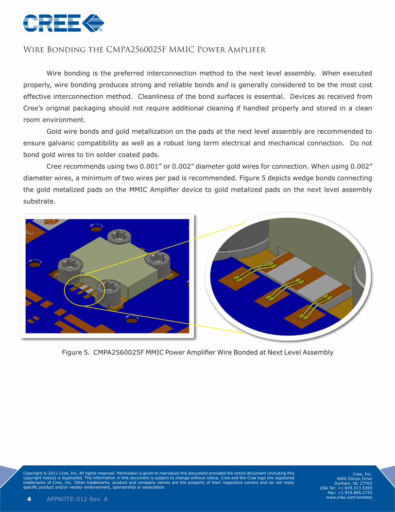
Cree recommends using two 0.001” or 0.002” diameter gold wires for connection. When using 0.002”
diameter wires, a minimum of two wires per pad is recommended. Figure 5 depicts wedge bonds connecting
the gold metalized pads on the MMIC Amplifier device to gold metalized pads on the next level assembly
substrate.
Figure 5. CMPA2560025F MMIC Power Amplifier Wire Bonded at Next Level Assembly

Copyright © 2011 Cree, Inc. All rights reserved. Permission is given to reproduce this document provided the entire document (including this copyright notice) is duplicated. The information in this document is subject to change without notice. Cree and the Cree logo are registered trademarks of Cree, Inc. Other trademarks, product and company names are the property of their respective owners and do not imply specific product and/or vendor endorsement, sponsorship or association.
5 APPNOTE-012 Rev. A
Cree, Inc.4600 Silicon Drive
Durham, NC 27703USA Tel: +1.919.313.5300
Fax: +1.919.869.2733www.cree.com/wireless
Gap Welding the CMPA2560025F MMIC Power Amplifer
The CMPA2560025F MMIC Power Amplifier may also be gap welded to the next level assembly.
Gap welding fuses the metal ribbon material to bond pad metal using pressure and heat. The amount of
pressure and heat required for gap welding exceeds that required for wire bonding, thereby yielding an
increased risk of damage to electrical components being welded. As a general rule, the user should not
specify gap welding where the application will allow for wire bonding. Gap welded interconnect ribbons are
illustrated in Figure 6.
If the substrate pads on the next level assembly are gold plated, Cree recommends using gold
ribbon. Gold ribbon ensures long term galvanic compatibility to the gold pads on the CMPA2560025F. Silver
ribbon is recommended for applications where the substrate pads on the next level assembly are tin or tin/
lead solder coated or plated.
MMIC Power Amplifier pad size dictates the maximum width of the gap weld ribbon to be 0.010”.
Ribbon thickness will vary based on the current flow required and the user’s gap weld process standards.
Figure 6. Illustration of CMPA2560025F MMIC Power Amplifier Gap Welded at Next Level Assembly

Copyright © 2011 Cree, Inc. All rights reserved. Permission is given to reproduce this document provided the entire document (including this copyright notice) is duplicated. The information in this document is subject to change without notice. Cree and the Cree logo are registered trademarks of Cree, Inc. Other trademarks, product and company names are the property of their respective owners and do not imply specific product and/or vendor endorsement, sponsorship or association.
6 APPNOTE-012 Rev. A
Cree, Inc.4600 Silicon Drive
Durham, NC 27703USA Tel: +1.919.313.5300
Fax: +1.919.869.2733www.cree.com/wireless
CMPA2560025F MMIC Power Amplifer with Gap Welded Interconnect Leads
As an alternate approach, for customers that do not have the
ability to gap weld ribbon interconnects to the CMPA2560025F MMIC
Power Amplifier traces, there are contract manufacturers offering
lead-attach as a service. One such company is SMT Manufacturing
Group. www.smt-llc.com SMT
Manufacturing Group will bond
0.010” wide by 0.001” thick
gold plated copper ribbon to
the CMPA2560025F pads as
illustrated in Figure 7. Greater
than 0.100” of excess ribbon
length is supplied for the next
level assembly per Figure 8.
Trim the leads as required, apply stress relief and solder the end of the leads to the next level
assembly substrate as illustrated in Figure 9.
Figure 7. CMPA2560025F MMIC
Power Amplifier with Gap Welded
Ribbon Interconnect Leads
Figure 8. Excess Interconnect
Supplied for Next Assembly
Figure 9. Illustration of CMPA2560025F Installed at Next Level Assembly

Copyright © 2011 Cree, Inc. All rights reserved. Permission is given to reproduce this document provided the entire document (including this copyright notice) is duplicated. The information in this document is subject to change without notice. Cree and the Cree logo are registered trademarks of Cree, Inc. Other trademarks, product and company names are the property of their respective owners and do not imply specific product and/or vendor endorsement, sponsorship or association.
7 APPNOTE-012 Rev. A
Cree, Inc.4600 Silicon Drive
Durham, NC 27703USA Tel: +1.919.313.5300
Fax: +1.919.869.2733www.cree.com/wireless
CMPA2560025F Installation Electrical Verification
To ensure proper alignment of the strips, it is important to perform electrical tests. This simple test
will verify proper installation and a properly functioning amplifier.
Connect the DC cable as per the ‘Turn On Instructions’ included in the kit. Apply 0.1 VDC to the drain
wire and 0.0 VDC to the gate wire. Proper operation will result in ~200-300 mA ID. Apply -5.0 VDC to the gate
wire, the ID should reduce to zero. (pinch-off). If you can verify the currents above, then you have a properly
installed the MMIC amplifier.