application guide - diamond kote · flashing, windows, doors & openings. 06-07. rigidmount...
TRANSCRIPT

1 | Wausau Siding Systems Application Guide 03.17
IMPORTANT: PLEASE READ BEFORE YOU BEGIN INSTALLATION. Before installing any projects with Wausau Siding Systems™ products it is highly recommended the entire installation guide is reviewed.
INDEX: 02 PRIOR TO INSTALL
02 GENERAL GUIDELINES
03 INSULATED SHEATHINGS
03 MOISTURE
03 WEATHER-RESISTANT BARRIER
04 STUD SPACING
04 GAPS + SEALANTS
04 TOUCH-UP PAINT GUIDELINES
04-05 TRIM
06 FLASHING, WINDOWS, DOORS & OPENINGS
06-07 RIGIDMOUNT APPLICATION
08 PRO-POST WRAP
09 KICK-OUT FLASHING
09-10 FASTENING
11 TRADITIONAL LAP APPLICATION
12-13 RIGIDSTACK APPLICATION
14 STRAIGHT EDGE SHAKES APPLICATION
15 STAGGERED EDGE APPLICATION
16 OCTAGON + SCALLOPS
17 OCTAGON APPLICATION
18 SCALLOP APPLICATION
19 OUTSIDE + INSIDE CORNER APPLICATION
20-21 TRIM WITH NAIL FIN APPLICATION
21 ARCH TRIM
22-25 BOARD + BATTEN APPLICATION
26-27 FASCIA APPLICATION
Application Guide
Click on the chapter heading to go directly to a specitifc section.

2 | Wausau Siding Systems Application Guide 03.17
PRIOR TO INSTALLATIONIt is important to properly store all Diamond Kote® pre-finished products for protection. • Store siding flat on a dry, clean and well
supported surface. Protect material from direct exposure to weather.
• Do not store directly on the ground.• Wausau Siding Systems™ 4-Packs and
2-Packs are not waterproof. All products must be kept dry and covered at all times.
• Product may come in long, heavy sections which requires proper handling.
• Carry shrink wrapped bundles to desired location before opening to avoid damaging the painted surface. Don't carry in a flat position.
• Pick up product from the center to avoid marring the surface of items below.
• Only carry multiple pieces of siding: face-to-face or back-to-back.
• Do not slide pre-finished siding material across each other.
• Support the product when you cut large pieces.
• Inspect product for any issues before installating it: breakage, surface defects, foreign objects, color in consistency or color correctness.
• Do not install questionable product. • Report any problems you may have to
your dealer BEFORE installing. • Sealed product could become saturated
if not protected during storage. • If the product becomes saturated, do not
install it until it dries out completely.
GENERAL GUIDELINES**Note: DO NOT USE STAPLES.Minimum 6" clearance must be maintained between siding and finish grade.• Siding applied adjacent to porches,
patios, walks, roof lines, etc. must have a 1" clearance above any surface.
• 3/8" clearance should be left between siding and horizontal flashings.
• All exposed wood substrate must be primed and painted in a manner that prevents moisture intrusion and water buildup.
• See Alternate Fastening Options for fastening lap siding to SIP, ICF and Steel Frame assemblies. (PG 10)
• Adequate drying time must be allowed prior to enclosing the wall cavity when using wet blown cellulose insulation.
• Wausau Siding Systems™ products should be cut in a manner to avoid marring the finished face.
• It is recommended to face the board up when using a combination blade power miter saw.
• Do NOT force or spring siding into place. Where siding butts window trim, door casing, masonry, etc., leave a 3/16" gap and caulk. DO NOT caulk butt joints.
• Seal all gaps with a paintable sealant that meets ASTM-C920 Specification, it is recommended to use DAP Spec Line 920.
• Use drip-cap flashing above all horizontal trim to ensure a weather-tight installation. 1" drip cap is available in all Diamond Kote colors.
STORE UNDER COVER PROPER HANDLING

3 | Wausau Siding Systems Application Guide 03.17
INSULATED SHEATHINGS Wausau Siding Systems™ products may be installed over low-compression rigid foam or exterior gypsum sheathings.
The following precautions must be followed:
• Nailable structural sheathing must be behind the insulated sheathing.
• Make sure to brace the wall accordingly to the required international and other building codes.
• For rigid foam sheathing up to 1" thick, siding may be nailed directly to the foam sheathing unless a drainage plane is required by the local building code. Nail length must be increased to ensure a minimum 1-1/2" fastener penetration into the structural framing.
Note: Wausau Siding Systems™ products may also be installed in compliance with category 8140-Exterior wall siding and sheathing for Wildland Urban Interface applications atop LP FlameBlock sheathing. Refer to FlameBlock installation instructions and product data sheets.
All Wausau Siding Systems products may be installed as exterior siding in Wildland Urban Interface applications. It can be installed over one layer 5/8" Type X gypsum sheathing applied behind the exterior covering or cladding on the exterior side of the framing. They may also be installed over the exterior
portion of a 1-hour fire-resistive exterior wall that has been assembly designed for exterior fire exposure which also includes assemblies using the gypsum panel and sheathing products listed in the Gypsum Association Fire Resistance Design Manual.• For rigid foam sheathing that is greater
than 1", a minimum 1-1/2" thick by 3-1/2" wide vertical strapping or furring strip must be installed over the sheathing to provide a solid, level nailing base for the siding. The strapping must be securely fastened to structural framing spaced no greater than 16" o.c. with a minimum fastener penetration of 1-1/2".
• Wausau Siding Systems will not assume any responsibility for conditions arising from the use of foam sheathing or damage.
MOISTURE• Moisture and vapor control are critical
elements of proper housing design. • Check local building codes for application
procedures for handling moisture and moisture vapor in your area.
• Do not apply engineered wood siding to a structure having excessive moisture conditions such as drying concrete or plaster or wet blown cellulose insulation.
• If such conditions exist, the building should be well ventilated to ensure the
substrate is completely dry prior to siding application.
• Siding must not be applied to any green or crooked structural framing members.
• Do not apply siding over rain-soaked or buckled sheathing materials.
• We recommend protection for your home from rainfall with gutters and downspouts. Always be sure that your drainage system is free of debris and working properly.
WEATHER-RESISTANT BARRIER• It is required to have a water-resistant,
properly breathable barrier behind the siding.
• When integrating flashing with a water-resistive barrier (WRB), be sure to follow the WRB installation instructions.
• Wausau Siding Systems will not assume responsibility for water penetration.
• Consult local building codes for more details.
TRIM & FASCIA 190, 440, 540 & 2000 SERIESINSTALLATION
• Trim ends may lightly touch adjacent trim edges around windows and doors only. Re-prime and paint all cut ends.
• When installing trim around windows and over window flanges, be sure to follow the window manufacturer’s installationinstructions.
• All openings must be properly sealed and flashed in a manner that prevents moisture intrusion or buildup. Flashing may besealed to the water-resistive barrier by using adhesive flashing or housewrap tape. (See ALL diagrams)
• When trim is installed adjoining vinyl siding, install Z-flashing with a 4 inch upper leg between horizontal trim and J-channel.(See diagram 8a)
• Horizontal trim or bands shall be flashed with a sloped metal Z-flashing to redirect water away from the wall assembly.
GENERAL REQUIREMENTS (CONTINUED)
7a
7b
Windows, Doors and Openings
7c
7d
7e
LP SmartSide Trim & Fascia
7
Housewrap Flap
Head Flashing
Jamb Flashing
Sill Flashing Window
Flashing
Housewrap Tape

4 | Wausau Siding Systems Application Guide 03.17
STUD AND SPACING• Wausau Siding Systems products must
be applied over sheathed walls into studs spaced no greater than 16" on center.
• When installing over masonry walls, the wall must be furred out with wood framing spaced 16" on center and with a adequate thickness to accept the full length of the recommended nail.
GAPS AND SEALANTSNote: DO NOT apply sealant to butt joints. • Seal all gaps with a paintable sealant
that meets ASTM C920 Specification.• We recommend the DAP Spec Line 920.
Check out the application instructions for the manufactured sealant or view our Proper Caulking Techniques Video.
TOUCH-UP PAINT GUIDELINES Before starting, read all label instructions and warnings. Diamond Kote® touch-up paint is intended for use on Diamond Kote pre-finished products only. We cannot guarantee the performance of Diamond Kote touch-up paint on products not originally pre-finished with Diamond Kote. Only apply paint to bare area. DO NOT APPLY PAINT OVER PAINT. *Do not allow touch-up paint to freeze. Keep container from freezing.*
For Touch- Up Paint, please do the following:• Paint all exposed cut edges of siding
surfaces including drip edges. • Apply a small amount of touch-up paint
using the provided foam brush to seal all cut edges. Avoid getting touch-up paint on the face of the boards and try not to apply more paint than what is needed.
• Thoroughly paint all the bottom edges of siding especially the cut ends next to the roof line. Touch-up paint all exposed face nails.
• Cotton swabs are recommended for touch-up painting on the finished face of products.
• Follow the Diamond Kote® application/maintenance instructions or watch the Diamond Kote Touch-Up Paint Best Practices Video.
PAINT CARE• Stir touch-up paint for ten minutes
before use. Heavier pigments in the paint settle to the bottom requiring the paint to be thoroughly mixed before use and clean up with water after.
SURFACE PREP• Surface must be clean and dry. Test the
color on a sample piece or hidden area of the siding/trim before applying. Do NOT fan out or try to blend the paint.
• Allow 24 hours dry time. Touch up nail heads or small imperfections by using a cotton swab to dot the desired area.
TRIM• Trim should be thick enough so the
siding does not extend beyond the face of the trim.
• Trim and fascia are not designed for siding/structural applications. It should not be used as a structural member in construction (trellis, railing, fencing, decking, decking trim or sills.)
• Trim must be applied so it will not allow moisture intrusion or water buildup.
• Lap siding and panel siding are not designed and/or manufactured to be used as trim allows.

5 | Wausau Siding Systems Application Guide 03.17
TRIM | FASTENER INFORMATION • Fastener length: Long enough to fully
penetrate structural framing or wood structural panels and structural framing a minimum of 1".
• Fastener placement: 3/8" from ends and edges, when framing support allows.
• Fastener spacing: Must be fastened with two nails at both ends, with additional fasteners spaced a maximum of 24 inches o.c. along the length of the board, or with additional fasteners spaced a max. of 12 inches o.c. along alternating edges the length of the board.
• Fastener quantity: For trim under 7 inches wide use a minimum of 2 nails per width. For trim 7 to 12 inches wide use a minimum of 3 nails per width. For trim over 12 inches wide use a minimum of 4 nails per width.
• Where edges of trim meet siding material, windows, etc., leave a min. 3/16 inch space to allow for proper sealing. Provide increased spacing along the trim if specified by the siding application instructions.
CUTTING • A fine-tooth carbide tipped blade is
recommended for the cleanest cut.• Trim and fascia are manufactured with
a special edge coating which reduces moisture-related issues.
• Do not rip and/or rout the trim and fascia, as it will leave the edges unprotected.
• If the trim/fascia materials are ripped you must take special care to prime, paint and seal all exposed wood fiber as described in the finishing section.
• Do not miter trim ends or edges. 45 degree diagonal cuts of trim ends around door and window opening is acceptable, as well as joining. (See below)
BUTT JOINTS FOR TRIM • Ends and butt joints require a 3/16 inch
space and seal with a high quality non-hardening paintable long-life sealant. Joints may lightly touch around windows and doors only.
• Butt joints require 4 nails with 2 nails on either side of the joint at each edge.
TRIM ADJOINING WITH OTHER MATERIALS• Trim with Stucco, Brick or Cultured Stone:
it is important to use a capillary break so moisture absorbed into the stucco, brick /cultured stone can not transfer into the trim. Avoid Direct Contact between the trim and stucco, brick or cultured stone.
• Separate with a min. 3/8-inch space and a high-quality sealant (backer rod may be required as per the sealant manufacturers instructions). Additional space may be required by the manufacturer of the stucco, brick or cultured stone cladding.
• Other types of material such as aluminum flashing can be used to separate the trim from the stucco, brick or cultured stone but dissimilar materials should be properly spaced to allow for different rates of thermal or moisture movement.
• Apply sloped Z-flashing over horizontal trim so water can be redirected to the outer surface of the wall.
TRIM & FASCIA 190, 440, 540 & 2000 SERIESPREPARATION
• Minimum 6 inches clearance must be maintained between trimand finished grade. (See diagram 2a)
• Trim applied adjacent to roofs, porches, patios, sidewalks, etc.must have a clearance of at least 1 inch above any surface wherewater might collect. The surface must be sloped or otherwisedesigned to provide proper drainage so the trim is at no timedirectly exposed to standing water. (See diagram 2b)
• A non-corrosive drip-edge must be applied at bottom edge ofroofing where it meets the fascia. (See diagrams 2c and 9c)
• In a horizontal brick frieze or band board application where thetrim meets the masonry leave a 3/8 inch minimum airspace andflash between the trim and the masonry. (See diagram 2d)
GENERAL REQUIREMENTS (CONTINUED)
• For the cleanest cut and longer blade life, a fine-tooth carbidetipped blade is recommended.
• Trim and fascia are manufactured with a special edge coatingwhich reduces moisture-related issues. Do not rip and/or routthe trim and fascia, as it will leave the edges unprotected. If thetrim or fascia materials are ripped you must take special care toprime, paint and seal all exposed wood fiber as described in thefinishing section.
• Climb cut the surface of the trim and fascia such that the rotationof the blade cuts downward on the primed or prefinishedsurface.
• Do not miter trim ends or edges. 45 degree diagonal cuts of trimends around door and window opening is acceptable, as well asjoining. (See diagram 2e)
2a
CUTTING
2b
2c
2d
2e
General Information (continued)
Cutting
LP SmartSide Trim & Fascia
2
Paint
TRIM & FASCIA 190, 440, 540 & 2000 SERIESINSTALLATION
LP SmartSide Trim Adjoining Vinyl Siding:
• Install vinyl siding meeting standards of manufacturersinstallation instructions and/or the Vinyl Siding Instutute’sManual.
• Horizontally adjoined trim and vinyl J-channel or utility trim:Install sloped Z-flashing with a minimum 4 inch upper leg.(See diagram 8a)
• Vertically adjoined trim and vinyl J-channel - J-channel should fitsnug to trim.
• Do not caulk between trim and J-channel or utility trim.
• Install the trim according to the LP SmartSide Trim and Fasciaapplication instructions.
GENERAL REQUIREMENTS (CONTINUED)LP® SmartSide® Trim Adjoining Other Materials
8a
8b
LP SmartSide Trim Adjoining Stucco, Brick or Cultured Stone:
When using LP SmartSide trim with stucco, brick or cultured stone, it is important to use a capillary break so moisture absorbed into the stucco, brick or cultured stone cannot transfer into the trim.
• Avoid Direct Contact between the trim and stucco, brick orcultured stone.
• Separate with a minimum 3/8-inch space and a high-qualitysealant (backer rod may be required as per the sealantmanufacturers instructions). Additional space may be requiredby the manufacturer of the stucco, brick or cultured stonecladding. (See diagram 8b)
• Other types of impervious material such as aluminum flashingcan be used to separate the trim from the stucco, brick orcultured stone but the dissimilar materials should be properlyspaced to allow for different rates of thermal or moisture-relatedmovement.
• Apply sloped Z-flashing over horizontal trim so water that mayget behind adjoining cladding can be redirected to the outersurface of the wall.
• Install the trim according to the LP SmartSide Trim and Fasciaapplication instructions.
• Install the stucco, brick or cultured stone cladding in a mannerconsistent with the manufacturers installation instructions.
LP SmartSide Trim & Fascia
8
WRB
Sheathing
Stucco, Brick or Cultured Sonte
Casing Bead
Sloped Z-Flashing (do not caulk) Casing Bead
Stucco, Brick or Cultured Sonte
Backer Rod and Sealant
TRIM & FASCIA 190, 440, 540 & 2000 SERIESINSTALLATION
• Butt joints: Ends and butt joints require a 3/16 inch spaceand seal with a high quality non-hardening paintable long-lifesealant. Joints may lightly touch around windows and doorsonly. Butt joints require four (4) nails with two nails on either sideof the joint at each edge. (See diagrams 4a, 5a and 5b)
GENERAL REQUIREMENTS (CONTINUED)
Alternative Fastening Option - Trim Nails• Common or box nails provide superior resistance to fastener pull-through. In Hurricane-Prone Regions or locations where
negative wind loads are a concern, box or common nails should be used. Trim nails may be used in other locations withthe following cautions: Do not overdrive or counter sink the fastener, nail flush with the surface of trim. Trim nails shall beinstalled per the length, placement, spacing and quantity requirements listed in this document. Detachment of trim is notcovered by the LP SmartSide limited warranty whether common, box, or trim nails are used.
Alternative Fastening Option over Wood Structural Panels - Sheathing Only Attachment: • Wood structural panels must be a minimum 7/16 Category with an APA Trademark that contains the consensus Standard
DOC PS 1 or PS 2.• Fastener Type:
− Ring-shank nail − Shank diameter = 0.091 inch − Hot-dipped galvanized (ASTM A153) or equal − Head diameter = 0.200 inch
• Fastener Length:− Fastener shall be long enough to fully penetrate through wood structural panel sheathing and extend by at least 1/4 inch
• Fastener Placement and Quantity:− Must be consistent with the LP® SmartSide® Trim and Fascia Application Instructions.
• Strictly adhered to all other aspects of the LP® SmartSide® Trim and Fascia Application Instructions.• Detachment of trim is not covered by LP SmartSide limited warranty whether fasteners penetrate studs or sheathing only
attachment is used.
Alternative Fastening Option - Attaching Trim as Batten Strips• Attachment of trim as batten strips where the trim is unable to be attached into wood structural panels and structural
framing a minimum of 1 inch will require additional support from a construction adhesive. First, use hot-dipped galvanizedring-shanked nails no smaller than 0.091 inch shank diameter to attach the trim sufficiently to secure the trim to thestructure while the construction adhesive completes its curing process. Second, use an exterior grade construction adhesivethat meets the following specifications.
Construction Adhesive Specifications: − Minimum bond strength: 300 psi − Minimum application temperature: 40° F − Paintable grade
Alternative Fastening Option - Installing Over Insulated SheathingsLP SmartSide Trim and Fascia may be installed over low-compression rigid foam or exterior gypsum. The following precautions must be followed: • Adequate bracing of the wall in accordance with the International Codes or other ruling building code is required.• For rigid foam sheathing up to 1 inch (25.4 mm) thick, trim may be nailed directly to the foam sheathing unless a drainage
plane is required by the local building code. Nail length must be increased to ensure a minimum 1-1/2 inches (38.1 mm)fastener penetration into the structural framing.
• For rigid foam sheathing greater than 1 inch (25.4 mm) thick, a minimum 1-1/2 inches (38.1 mm) thick by 3-1/2 inches(88.9 mm) wide vertical strapping or furring strip must be installed over the sheathing to provide a solid, level nailing basefor the trim. The strapping must be securely fastened to structural framing spaced no greater than 16 inches o.c. (406 mm)with a minimum nail penetration of 1-1/2 inches (38.1 mm) and a maximum nail spacing no greater than the width of thesiding.
Louisiana-Pacific assumes no responsibility for any damage or condition arising from the use of rigid foam or exteriorgypsum.
5b5a
Fastening Instructions (continued)
LP SmartSide Trim & Fascia
5
DO NOT use scarf joints
TRIM & FASCIA 190, 440, 540 & 2000 SERIESINSTALLATION
• Butt joints: Ends and butt joints require a 3/16 inch spaceand seal with a high quality non-hardening paintable long-lifesealant. Joints may lightly touch around windows and doorsonly. Butt joints require four (4) nails with two nails on either sideof the joint at each edge. (See diagrams 4a, 5a and 5b)
GENERAL REQUIREMENTS (CONTINUED)
Alternative Fastening Option - Trim Nails• Common or box nails provide superior resistance to fastener pull-through. In Hurricane-Prone Regions or locations where
negative wind loads are a concern, box or common nails should be used. Trim nails may be used in other locations withthe following cautions: Do not overdrive or counter sink the fastener, nail flush with the surface of trim. Trim nails shall beinstalled per the length, placement, spacing and quantity requirements listed in this document. Detachment of trim is notcovered by the LP SmartSide limited warranty whether common, box, or trim nails are used.
Alternative Fastening Option over Wood Structural Panels - Sheathing Only Attachment: • Wood structural panels must be a minimum 7/16 Category with an APA Trademark that contains the consensus Standard
DOC PS 1 or PS 2.• Fastener Type:
− Ring-shank nail − Shank diameter = 0.091 inch − Hot-dipped galvanized (ASTM A153) or equal − Head diameter = 0.200 inch
• Fastener Length:− Fastener shall be long enough to fully penetrate through wood structural panel sheathing and extend by at least 1/4 inch
• Fastener Placement and Quantity:− Must be consistent with the LP® SmartSide® Trim and Fascia Application Instructions.
• Strictly adhered to all other aspects of the LP® SmartSide® Trim and Fascia Application Instructions.• Detachment of trim is not covered by LP SmartSide limited warranty whether fasteners penetrate studs or sheathing only
attachment is used.
Alternative Fastening Option - Attaching Trim as Batten Strips• Attachment of trim as batten strips where the trim is unable to be attached into wood structural panels and structural
framing a minimum of 1 inch will require additional support from a construction adhesive. First, use hot-dipped galvanizedring-shanked nails no smaller than 0.091 inch shank diameter to attach the trim sufficiently to secure the trim to thestructure while the construction adhesive completes its curing process. Second, use an exterior grade construction adhesivethat meets the following specifications.
Construction Adhesive Specifications: − Minimum bond strength: 300 psi − Minimum application temperature: 40° F − Paintable grade
Alternative Fastening Option - Installing Over Insulated SheathingsLP SmartSide Trim and Fascia may be installed over low-compression rigid foam or exterior gypsum. The following precautions must be followed: • Adequate bracing of the wall in accordance with the International Codes or other ruling building code is required.• For rigid foam sheathing up to 1 inch (25.4 mm) thick, trim may be nailed directly to the foam sheathing unless a drainage
plane is required by the local building code. Nail length must be increased to ensure a minimum 1-1/2 inches (38.1 mm)fastener penetration into the structural framing.
• For rigid foam sheathing greater than 1 inch (25.4 mm) thick, a minimum 1-1/2 inches (38.1 mm) thick by 3-1/2 inches(88.9 mm) wide vertical strapping or furring strip must be installed over the sheathing to provide a solid, level nailing basefor the trim. The strapping must be securely fastened to structural framing spaced no greater than 16 inches o.c. (406 mm)with a minimum nail penetration of 1-1/2 inches (38.1 mm) and a maximum nail spacing no greater than the width of thesiding.
Louisiana-Pacific assumes no responsibility for any damage or condition arising from the use of rigid foam or exteriorgypsum.
5b5a
Fastening Instructions (continued)
LP SmartSide Trim & Fascia
5
3/8" from ends and edges
3/16" Space
TRIM & FASCIA 190, 440, 540 & 2000 SERIESPREPARATION
• Moisture control and moisture vapor control are critical elements of proper housing design and construction. Check yourlocal building codes for application procedures for handling moisture and water vapor in your area.
• Follow all applicable building code specifications relating to prevention of moisture intrusion into the wall assembly. LPSmartSide trim and fascia is a wood product, and, as with all wood products, must be kept free from excessive moisture.Lack of proper ventilation; exposure to constant or repetitive sources of water such as sprinklers, condensation, inadequateflashing; improper sealing; or failure to follow common building practices that prevent moisture intrusion into the wallsystem may cause damage, and products subject to such treatment will be excluded from warranty coverage.
• As with all wood products, do not apply engineered wood trim and fascia to a structure having excessive moistureconditions such as drying concrete, plaster, or wet blown cellulose insulation. If such conditions exist, the building should bewell ventilated to allow it to dry prior to the application of the trim and fascia.
• Gutters with kick-out flashing and eave drip edge are recommended for control of roof water run off.
GENERAL REQUIREMENTS (CONTINUED)
• Apply nails to meet the specifications in the General ApplicationEquipment section in this document. (See diagram 3c)
• For edge-nailing, all nail holes must be pre-drilled. Do notattempt to edge nail without pre-drilling.(See diagrams 6e and 6f )
• Fastener length: Long enough to fully penetrate structuralframing or wood structural panels and structural framing aminimum of 1 inch.(See diagram 4a)
• Fastener placement: 3/8 inch from ends and edges, whenframing support allows.
• Fastener spacing: Trim must be fastened with two nails at bothends, with additional fasteners spaced a maximum of 24 incheso.c. along the length of the board, or with two nails at both ends,with additional fasteners spaced a maximum of 12 inches o.c.along alternating edges the length of the board.(See diagram 4b)
• Fastener quantity: For trim under 7 inches wide use a minimumof 2 nails per width. For trim 7 to 12 inches wide use a minimumof 3 nails per width. For trim over 12 inches wide use a minimumof 4 nails per width.
• Where edges of trim meet siding material, windows, doors orother finished openings, leave a minimum 3/16 inch space toallow for proper sealing. Provide increased spacing along thetrim if specified by the siding application instructions.
• Do not miter corner joints of band boards, fascia, corner trim,etc. (See diagram 2e)
4a
CUTTING
4b
Moisture Control
Fastening Instructions
INSTALLATION
LP SmartSide Trim & Fascia
4
24" Max
12" Max
12" Max
Never nail into edges without pre-drilling
Do not miter edges
Never nail into edges without pre-drilling
Fastener spacing

6 | Wausau Siding Systems Application Guide 03.17
FLASHING FOR WINDOWS, DOORS + OPENINGS • Trim ends may lightly touch adjacent
trim edges around windows and doors only. Paint all cut ends.
• When installing trim around windows and over window flanges, be sure to follow the window manufacturer's installation instructions.
• All openings must be properly sealed and flashed in a manner that prevents moisture intrusion or buildup.
• Siding or trim applied adjacent to porches, patios, walks, etc. must have a clearance of at least 1" above any surface.
• Flashing may be sealed to the water-resistive barrier by using adhesive flashing or housewrap tape. (See ALL
diagrams in middle collumn)
• The surface must be sloped or otherwise designed to provide proper drainage so the siding is at no time directly exposed to standing water.
• Horizontal trim or bands shall be flashed with a sloped metal Z-flashing to redirect water away from the wall assembly.
RIGIDMOUNT™ Ensure the penetration is sealed and/or flashed properly by integrating it into the weather-resistive barrier. RigidMount trim should extend beyond the face of the siding. Watch our RigidMount Installation Video.
APPLICATION OF UNIVERSAL , OVERSIZED, UL ELECTRICAL, RECEPTACLE MOUNTS & SPLIT BLOCK• Prepare the RigidMount for the
application needed. Some cutting maybe necessary for fitment of your specific situation.
• Cuts should always be re-sealed with touch up paint.
• A jigsaw works best for cutting, be sure to cut from the back to keep the finished surface intact.
• Set the mount into position and mark the weather resistive barrier by using the nail holes (about 1/2" above the built in flashing) and the outside edges of the flange.
• Remove the mount and slit the weather resistive barrier horizontally (slightly wider than the top flange across those marks) creating a flap in the weather resistive barrier.
• Next install the RigidMount by slipping the top of the nailing flange under the weather resistive barrier flap.
CONTINUED ON NEXT PAGE
TRIM & FASCIA 190, 440, 540 & 2000 SERIESINSTALLATION
• Trim ends may lightly touch adjacent trim edges around windows and doors only. Re-prime and paint all cut ends.
• When installing trim around windows and over window flanges, be sure to follow the window manufacturer’s installationinstructions.
• All openings must be properly sealed and flashed in a manner that prevents moisture intrusion or buildup. Flashing may besealed to the water-resistive barrier by using adhesive flashing or housewrap tape. (See ALL diagrams)
• When trim is installed adjoining vinyl siding, install Z-flashing with a 4 inch upper leg between horizontal trim and J-channel.(See diagram 8a)
• Horizontal trim or bands shall be flashed with a sloped metal Z-flashing to redirect water away from the wall assembly.
GENERAL REQUIREMENTS (CONTINUED)
7a
7b
Windows, Doors and Openings
7c
7d
7e
LP SmartSide Trim & Fascia
7
Housewrap Flap
Head Flashing
Jamb Flashing
Still Flashing
Window Flange
Housewrap Tape
TRIM & FASCIA 190, 440, 540 & 2000 SERIESINSTALLATION
• Trim ends may lightly touch adjacent trim edges around windows and doors only. Re-prime and paint all cut ends.
• When installing trim around windows and over window flanges, be sure to follow the window manufacturer’s installationinstructions.
• All openings must be properly sealed and flashed in a manner that prevents moisture intrusion or buildup. Flashing may besealed to the water-resistive barrier by using adhesive flashing or housewrap tape. (See ALL diagrams)
• When trim is installed adjoining vinyl siding, install Z-flashing with a 4 inch upper leg between horizontal trim and J-channel.(See diagram 8a)
• Horizontal trim or bands shall be flashed with a sloped metal Z-flashing to redirect water away from the wall assembly.
GENERAL REQUIREMENTS (CONTINUED)
7a
7b
Windows, Doors and Openings
7c
7d
7e
LP SmartSide Trim & Fascia
7
Adhesive Flashing Z-Flashing
(do not caulk)
Nails 24" o.c. max
Shim window and door trim so it is installed on level wall plane
TRIM & FASCIA 190, 440, 540 & 2000 SERIESINSTALLATION
• Trim ends may lightly touch adjacent trim edges around windows and doors only. Re-prime and paint all cut ends.
• When installing trim around windows and over window flanges, be sure to follow the window manufacturer’s installationinstructions.
• All openings must be properly sealed and flashed in a manner that prevents moisture intrusion or buildup. Flashing may besealed to the water-resistive barrier by using adhesive flashing or housewrap tape. (See ALL diagrams)
• When trim is installed adjoining vinyl siding, install Z-flashing with a 4 inch upper leg between horizontal trim and J-channel.(See diagram 8a)
• Horizontal trim or bands shall be flashed with a sloped metal Z-flashing to redirect water away from the wall assembly.
GENERAL REQUIREMENTS (CONTINUED)
7a
7b
Windows, Doors and Openings
7c
7d
7e
LP SmartSide Trim & Fascia
7
WRB
SidingAdhesiveFlashingZ-Flashing 3/8" min. space (do not caulk)
Shim
Trim
Z-Flashing 3/8" min. space (do not caulk)
Top of Window
Bottom of Window
Sealant 3/16" min. space
Sill Flashing
Trim
Shim
Sealant 3/16" min. space
WRB
Siding
TRIM & FASCIA 190, 440, 540 & 2000 SERIESINSTALLATION
• Trim ends may lightly touch adjacent trim edges around windows and doors only. Re-prime and paint all cut ends.
• When installing trim around windows and over window flanges, be sure to follow the window manufacturer’s installationinstructions.
• All openings must be properly sealed and flashed in a manner that prevents moisture intrusion or buildup. Flashing may besealed to the water-resistive barrier by using adhesive flashing or housewrap tape. (See ALL diagrams)
• When trim is installed adjoining vinyl siding, install Z-flashing with a 4 inch upper leg between horizontal trim and J-channel.(See diagram 8a)
• Horizontal trim or bands shall be flashed with a sloped metal Z-flashing to redirect water away from the wall assembly.
GENERAL REQUIREMENTS (CONTINUED)
7a
7b
Windows, Doors and Openings
7c
7d
7e
LP SmartSide Trim & Fascia
7
Z-Flashing 3/8" min. space (do not caulk)
Sealant 3/16"min. space
Sealant 3/16"min. space
Sealant 3/16"min. space

7 | Wausau Siding Systems Application Guide 03.17
RIGIDMOUNT™ continued
• Set the mount at the correct elevation, level and then fasten the RigidMount to the wall filling every hole in nail flange. Hand driven galvanized roofing nails are recommended for fastening, such as 1-3/4" Maze STORMGUARD®.
• Place the adhesive flashing tape over the top of the RigidMount™ flange making sure to cover nailing holes.
• Fold the flap down and seal the slit in the weather resistive barrier with compatible building tape.
• This single fashion installation helps shed bulk water out and away from the structure.
• Install siding around the mount and leave the proper spacing between the RigidMount placement flange and the siding. (Min. 3/16")
• Note that the top course of siding should be cut 3/8" above the built in flashing as measured from the face of the siding.
• Make sure to seal cut edges of siding with provided touch-up paint. This area should be left un-caulked.
• Finish by applying sealant, starting approximately 3/4" in from the top corner and then working your way out, down the side, and across the bottom.
• Also seal the space between the wall penetrating material and the RigidMount cut out.
• DAP® Spec Line 920 sealant which meets ASTM-C920 Specification is recommended.
RIGIDMOUNT SPLIT BLOCK • After preparing the RigidMount™ Split
Block as detailed above, remove the loose lower half of the mount (set this aside until later).
• Feed the pipe or other application through the rectangular flange hole.
• For remodel applications it may be necessary to cut the bottom of the placement flange to slip this over certain items.
• Install the RigidMount Split Block as you would the rest of the mounts. (see pg. 6)
• Then, install the lower half of the Split Block by applying a small bead of color matching sealant to the joint as shown below.
• Next, slide the bottom half of the block back up until the joint is tight.
• No fasteners should be needed to secure lower half of split block.
TRIM & FASCIA 190, 440, 540 & 2000 SERIESINSTALLATION
• If framing around an existing column, be sure to use pressuretreated lumber in all locations that may be touching concrete,masonry or decking. Provide adequate framing support for thetrim to be properly fastened. (See diagram 11a)
• Be sure to use proper flashing with a minimum 4 inch upper leg.A secondary water-resistive barrier is recommended as well.
• Maintain a 3/8 inch space, and do not caulk, between trim andflashing. (See diagram 11b)
• Maintain a minimum 1 inch clearance between LP SmartSideproducts and any surface where water might collect.(See diagram 11b)
• Fasten all trim over 11 inches wide a maximum of every 6inches o.c. around the perimeter and every 12 inches o.c.along intermediate supports. For trim under 11 inches wide,fastener placement and quantity must be consistent with LP®SmartSide® Trim and Fascia Application Instructions.(See diagram 11b)
• Be sure to prime and paint all expose substrate surfaces and cuts.
• TRIM MUST NOT BE IN DIRECT CONTACT WITH MASONRY,CONCRETE, BRICK, STONE, STUCCO OR MORTAR.
GENERAL REQUIREMENTS (CONTINUED)
• Trim mounting blocks should extend beyond the face of the siding.• Prime and paint all cut ends, edges and holes.On-site assembled:• Use metal Z-flashing with a minimum 4 inch upper leg over the top side of trim mounting block. Leave a minimum 3/8 inch
space above Z-flashing and do not caulk. (See diagram 11d)• Properly integrate the Z-flashing with the housewrap. (See diagram 11c)• Apply fasteners meeting the specifications in this document.Pre-assembled:• Properly integrate the built-in placement flange and flashing with the housewrap. (See diagram 11c)• Fasten the built-in-placement flange to the framing meeting the pre-assembled trim mounting block manufacturer’s
instructions.• When installing pre-assembled trim mounting blocks, leave proper spacing at the two sides and bottom between the
built-in-placement flange and the siding (minimum 3/16 inch). Seal these spaces with sealant. (See diagram 11d)• Seal the space between the wall-penetrating material or fixture and the mounting block cut-out. (See diagram 11d)
11a
CUTTING
11b
11c 11d
6” o.c.
Column Application
Mounting Blocks for Exterior Fixtures
LP SmartSide Trim & Fascia
11
front
sealant
Housewrap Flap
Adhesive Flashing
Housewrap Tape
Min. 3/16" space with sealant
Min. 3/8" space (do not caulk)
Min. 3/16" space with sealant
8 | Wausau Siding Systems Application Guide 03.17
PRO-POST WRAP™ Pro-Post Wraps are NOT engineered for structural load-bearing use. These are designed for decorative wraps around structural and non-structural nominal 4x4, 4x6, and 6x6 posts. Ensure that areas above brick or stone ledges are properly flashed before installing wraps.
• A min. 3/8" clearance should be maintained between Pro-Post Wraps™ and metal flashings and a minimum 1" clearance must be maintained between Pro-Post Wrap™ and concrete or decks.
PREPARE INSTALLATION:• Glue all joints with a high quality, fast
set, weather resistive adhesive. Be sure to keep glue warm for proper spread rates.
• Use adhesive with minimum shear strength of no less than 300 psi, as tested in accordance with ASTM D905 Standard Test Method for Strength Properties of Adhesive Bonds in Shear by Compression Loading. We recommend DAP Rapid Fuse Wood Adhesive.
• Special care must be taken when assembling 4x6 Pro-Post Wraps™.
• Please note details on proper gluing.
• Measure each post locations separately as there may be variance from post to post. Out of office
INSTALLATION • Begin by cutting all four sides to the
desired length.
• Be sure to repaint all cut ends of the Pro-Post Wrap™ with Diamond Kote® touch- up paint before assembly.
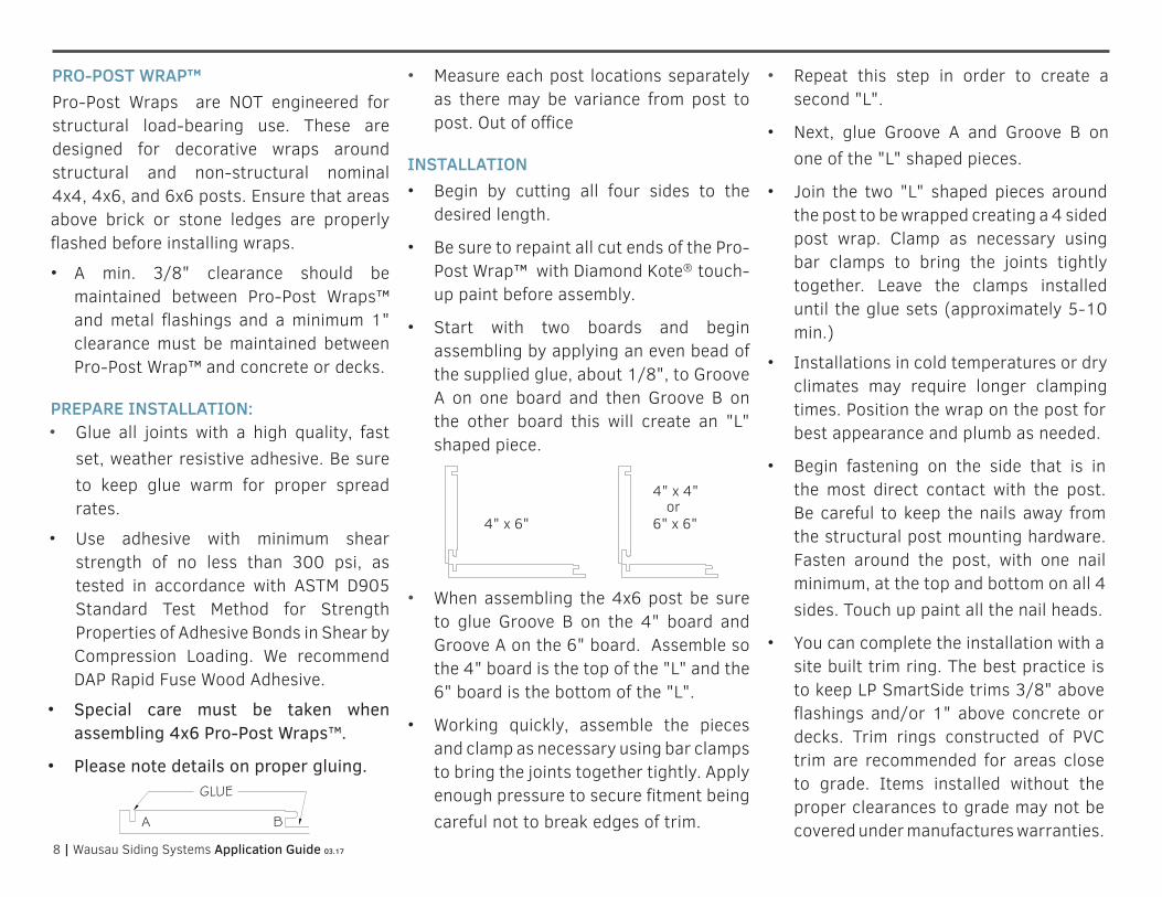
• Start with two boards and begin assembling by applying an even bead of the supplied glue, about 1/8", to Groove A on one board and then Groove B on the other board this will create an "L" shaped piece.
• When assembling the 4x6 post be sure to glue Groove B on the 4" board and Groove A on the 6" board. Assemble so the 4" board is the top of the "L" and the 6" board is the bottom of the "L".
• Working quickly, assemble the pieces and clamp as necessary using bar clamps to bring the joints together tightly. Apply enough pressure to secure fitment being careful not to break edges of trim.
• Repeat this step in order to create a second "L".
• Next, glue Groove A and Groove B on one of the "L" shaped pieces.
• Join the two "L" shaped pieces around the post to be wrapped creating a 4 sided post wrap. Clamp as necessary using bar clamps to bring the joints tightly together. Leave the clamps installed until the glue sets (approximately 5-10 min.)
• Installations in cold temperatures or dry climates may require longer clamping times. Position the wrap on the post for best appearance and plumb as needed.
• Begin fastening on the side that is in the most direct contact with the post. Be careful to keep the nails away from the structural post mounting hardware.Fasten around the post, with one nail minimum, at the top and bottom on all 4 sides. Touch up paint all the nail heads.
• You can complete the installation with a site built trim ring. The best practice is to keep LP SmartSide trims 3/8" above flashings and/or 1" above concrete or decks. Trim rings constructed of PVC trim are recommended for areas close to grade. Items installed without the proper clearances to grade may not be covered under manufactures warranties.
4" x 6" 6" x 6"
4" x 4" or
9 | Wausau Siding Systems Application Guide 03.17
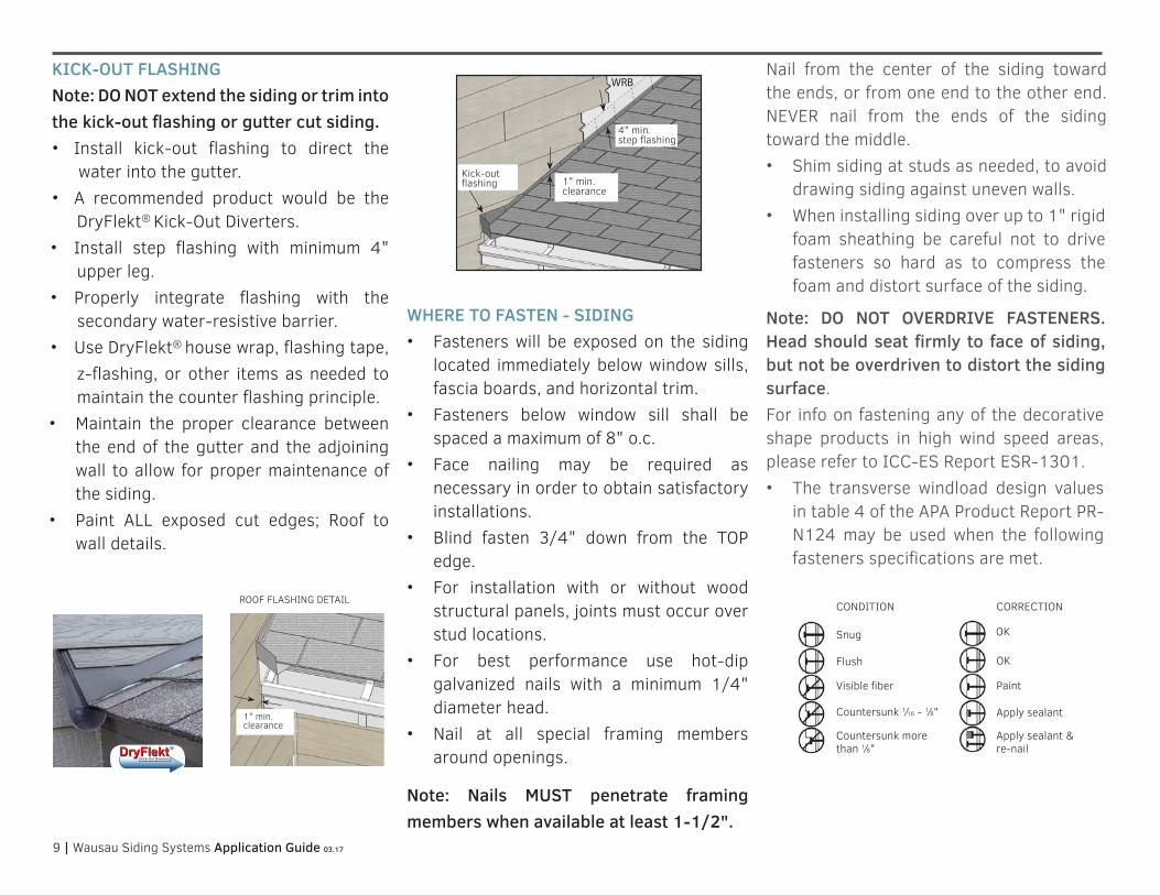
KICK-OUT FLASHINGNote: DO NOT extend the siding or trim into the kick-out flashing or gutter cut siding. • Install kick-out flashing to direct the
water into the gutter. • A recommended product would be the
DryFlekt® Kick-Out Diverters.• Install step flashing with minimum 4"
upper leg.• Properly integrate flashing with the
secondary water-resistive barrier. • Use DryFlekt® house wrap, flashing tape,
z-flashing, or other items as needed to maintain the counter flashing principle.
• Maintain the proper clearance between the end of the gutter and the adjoining wall to allow for proper maintenance of the siding.
• Paint ALL exposed cut edges; Roof to wall details.
WHERE TO FASTEN - SIDING• Fasteners will be exposed on the siding
located immediately below window sills, fascia boards, and horizontal trim.
• Fasteners below window sill shall be spaced a maximum of 8" o.c.
• Face nailing may be required as necessary in order to obtain satisfactory installations.
• Blind fasten 3/4" down from the TOP edge.
• For installation with or without wood structural panels, joints must occur over stud locations.
• For best performance use hot-dip galvanized nails with a minimum 1/4" diameter head.
• Nail at all special framing members around openings.
Note: Nails MUST penetrate framing members when available at least 1-1/2".
Nail from the center of the siding toward the ends, or from one end to the other end. NEVER nail from the ends of the siding toward the middle.• Shim siding at studs as needed, to avoid
drawing siding against uneven walls.• When installing siding over up to 1" rigid
foam sheathing be careful not to drive fasteners so hard as to compress the foam and distort surface of the siding.
Note: DO NOT OVERDRIVE FASTENERS. Head should seat firmly to face of siding, but not be overdriven to distort the siding surface.For info on fastening any of the decorative shape products in high wind speed areas, please refer to ICC-ES Report ESR-1301.• The transverse windload design values
in table 4 of the APA Product Report PR-N124 may be used when the following fasteners specifications are met.
TRIM & FASCIA 190, 440, 540 & 2000 SERIESPREPARATION
• Properly installed flashing materials will help direct water awayfrom common water collecting areas.
• All flashing material shall be metal or another durable materialthat under normal outdoor environmental conditions will last fora period of not less than 50 years.
• All flashing materials must have a minimum 4 inch upper leg.Add a 4 inch wide adhesive flashing to flashing legs less than4 inches.
• Properly integrate flashing with the secondary WRB. Usehousewrap, flashing tape, kick-out flashing, step flashing,Z-flashing, drip edge, gutters or other items as needed tomaintain the counter-flashing principle.
• Install kick-out flashing to direct the water into the gutter.(See diagram 3a)
• Install step flashing that has a minimum 4 inch upper leg.(See diagram 3a)
• Maintain a minimum 1 inch clearance between the end of thegutter and the adjoining wall to allow for proper maintenance ofthe siding. (See diagram 3b)
• Do not extend the siding or trim into the kick-out flashing orgutter.
• Prime and paint ALL exposed cut edges of siding and trim.
GENERAL REQUIREMENTS (CONTINUED)
• FASTENERS: Minimum 8d (0.113 inch diameter shank), hot-dipped galvanized or stainless steel nail with a 0.270 inchdiameter head. Apply and treat nailing errors as specified by these instructions. (See diagram 3c)
• SEALANT: Use an exterior-quality, non-hardening, paintable sealant. Use Class 25 or higher exterior sealant meeting theASTM C920 Standard for Specification for Elastomeric Joint Sealants. Follow the sealant manufacturer’s instructions forapplication.
• PAINT: Exterior-quality 100% acrylic latex paint, specially formulated for use on wood and engineered wood substrates, ishighly recommended. Semi-gloss or satin finish oil or alkyd paints are acceptable. For flat alkyd paint, please check with thecoating manufacturer for their recommendations for use on composite wood siding.
3a
CUTTING
3b
3c
Water Run-Off Control
General Application Equipment
WRB
LP SmartSide Trim & Fascia
3
4" min. step flashing
1" min. clearance
Kick-out flashing
ROOF FLASHING DETAIL
TRIM & FASCIA 190, 440, 540 & 2000 SERIESPREPARATION
• Properly installed flashing materials will help direct water awayfrom common water collecting areas.
• All flashing material shall be metal or another durable materialthat under normal outdoor environmental conditions will last fora period of not less than 50 years.
• All flashing materials must have a minimum 4 inch upper leg.Add a 4 inch wide adhesive flashing to flashing legs less than4 inches.
• Properly integrate flashing with the secondary WRB. Usehousewrap, flashing tape, kick-out flashing, step flashing,Z-flashing, drip edge, gutters or other items as needed tomaintain the counter-flashing principle.
• Install kick-out flashing to direct the water into the gutter.(See diagram 3a)
• Install step flashing that has a minimum 4 inch upper leg.(See diagram 3a)
• Maintain a minimum 1 inch clearance between the end of thegutter and the adjoining wall to allow for proper maintenance ofthe siding. (See diagram 3b)
• Do not extend the siding or trim into the kick-out flashing orgutter.
• Prime and paint ALL exposed cut edges of siding and trim.
GENERAL REQUIREMENTS (CONTINUED)
• FASTENERS: Minimum 8d (0.113 inch diameter shank), hot-dipped galvanized or stainless steel nail with a 0.270 inchdiameter head. Apply and treat nailing errors as specified by these instructions. (See diagram 3c)
• SEALANT: Use an exterior-quality, non-hardening, paintable sealant. Use Class 25 or higher exterior sealant meeting theASTM C920 Standard for Specification for Elastomeric Joint Sealants. Follow the sealant manufacturer’s instructions forapplication.
• PAINT: Exterior-quality 100% acrylic latex paint, specially formulated for use on wood and engineered wood substrates, ishighly recommended. Semi-gloss or satin finish oil or alkyd paints are acceptable. For flat alkyd paint, please check with thecoating manufacturer for their recommendations for use on composite wood siding.
3a
CUTTING
3b
3c
Water Run-Off Control
General Application Equipment
WRB
LP SmartSide Trim & Fascia
3
1" min. clearance
Snug
CONDITION CORRECTION
Flush
Visible fiber
Countersunk 1⁄16 - 1⁄8"
Countersunk more than 1⁄8"
OK
Paint
Apply sealant
Apply sealant & re-nail
OK

10 | Wausau Siding Systems Application Guide 03.17
ALTERNATIVE FASTENING OPTION: FOR WOOD STRUCTURAL PANELS + 24" O.C. STUD SPACING OR SIP ASSEMBLIESThe sheathing must be a minimum 7/16" thickness with an APA rating. The Engineered Wood Association™ that contains the consensus standard DOC PS2. • Note: Must be fastened with either
corrosion resistant screws or corrosion resistant ring shank nails.
• Minimum 6d (0.091 in. shank diameter) hot-dip galvanized ring shank nail with a 0.200 in. diameter head, spaced a maximum of 8 in. O.C.
ALTERNATIVE FASTENING OPTION: OVER ICF ASSEMBLIES • Minimum #8 hot-dip galvanized tapered
head self-drilling screw with a 0.270" diameter head.
• Minimum penetration of 3/8" beyond the thickness of the nailing flange.
Note: Larger screws may be required by the I.C.F. Manufacturer based on the following minimum withdrawal requirements.• Keep a minimum withdrawal value of
I.C.F. nailing flange must be 50 lbs. with a maximum 12" o.c. screw spacing.
• Keep a minimum withdrawal value of I.C.F. nailing flange must be 31 lbs. with a maximum 6" o.c. screw spacing.
Figure 1F Figure 1E Figure 1D
OUTSIDE CORNER DETAIL
INSIDE CORNER DETAIL
BOTTOM COURSE DETAIL
GAP 3/16" AND SEAL
GAP 3/16" AND SEAL
Starter Strip
Figure 1B Figure 1C
Figure 1
4" min. flashing
1" min. clearance from roofing
Trim
Min. 3/16" gap
Paint bottom edges
Figure 1A
ROOF FLASHING DETAIL JOINT TREATMENT OVER OPENINGS
Vapor Retarder
Breathable weather resistant barrier

11 | Wausau Siding Systems Application Guide 03.17
OPTIONS OVER CORROSION RESISTANT STEEL STUD FRAMING Keep a minimum withdrawal value of steel framing must be 50 lbs. • Refer to the framing manufacturer's
evaluation report.38 Series Precision lap must be fastened
with the following:• Steel stud spacing a maximum spacing of
16" o.c. • Minimum #8 hot-dipped galvanized
tapered head self-drilling screw with 0.270" diameter head.
• Keep a min. of 5 threads beyond the combined thickness of the siding and framing.
• Minimum steel framing thickness 0.032"/ 20 gauge.
TRADITIONAL LAP APPLICATIONSPACER CLIPS• Hook clip to top of the first row of siding.• Slide siding down into clip shelf.• Follow the manufacturers directions
for nailing and then strike the clip with hammer to knock it off.
Note: Spacer clip is intended for alignment and spacing only. It's not intended to support the weight of the siding. Break off clips before siding is completely nailed tight.
JOINT PREPARATIONS H-MOLDINGNote: H-Moldings DO NOT space the board for expansion. H-Moldings are designed to cover the expansion gap. • Leave a 1/4" gap between the siding
pieces. 3/16" gap plus the thickness of H-Molding web equals 1/4".
• Apply both adjoining pieces of the siding, fasten along the entire length (except for the ends) with the required gap. Be sure to butt the factory painted ends of the board over the stud.
• Then, slide the H-Molding in place, from the bottom of the siding up, with the notched end of the molding down. Slightly bend outward on the flanges to help the H-Molding slide into place. (See Figure 2a)
• Finish fastening by nailing both pieces of siding at the end of the siding. Angle the nails slightly to hit the stud.
• At butt joints, fasteners should be driven 3/4" down from the top and 3/8" in from the ends.
• Fasteners below a window sill need to be spaced a maximum of 8" o.c. Fasteners will be exposed on the siding located immediately below window sills, fascia boards, and horizontal trim.
• When attaching siding, avoid nailing closer than 1-1/2" from the end of the board so the power nail does not penetrate the nail fin of Wausau Siding System Trims.
Figure 2a
Bend slightly outward on the flanges
Install with this end down

12 | Wausau Siding Systems Application Guide 03.17
RIGIDSTACK™ APPLICATION • Apply RigidStack siding over properly
prepared walls. (see general information)
• Wausau Siding Systems™ RigidStack™ is installed as a blind fastened technique.
• It can be installed by starting with a RigidStack Metal Starter Strip, or by stacking onto a Wausau Siding Systems Starter Board.
• Begin by installing Wausau Siding Systems Outside Corners and Trim.
• Next, install the appropriate starter material being sure to keep the bottom of the RigidStack at least 6" from finished grade.
INSTALL RIGIDSTACK USING STARTER BOARDStarter Board can be installed at or below finished grade. Best practice is to install this with Fasten Master Cortex® Hidden Fastening System for PVC. Install Starter Board using Cortex Hidden Fastening System in the following manner:
• Be sure to snap a level line as this will set the exact placement for the first course of RigidStack siding. (Figure 2b)
• If the board is 6-12" wide, use three Cortex fasteners at every framing member.
• If the board is less than 6" wide, use two Cortex fasteners at every framing member. For more info refer to CertainTeed Restoration Millwork® installation instructions.
• Using the Cortex setting tool, set the Cortex fasteners perpendicular to the trim board, spaced a max. of 16" o.c.
• Using a standard 18V cordless impact drill, drive the fastener to the pre-set level below the trim surface.
• Place the PVC trim plug into the hole with the trim-surface-side up and gently tap until it is flush with the trim board.
• Finish by painting the plugs with Diamond Kote® touch-up paint and a cotton swab.
INSTALL USING RIGIDSTACKMETAL STARTER STRIP• The bottom edge of RigidStack metal
starter strip should be installed at the foundation along the sill plate or up to 1-1/8" below this to properly hold the bottom of RigidStack in place.
• Placement may vary as required by course layout. (see Figure 2c)
• Snap a level chalk line 3-3/8" above the bottom of where the first course of siding will start. Align the TOP of the metal starter strip on the chalk line. RigidStack metal starter strip will set the exact placement for the 1st course of RigidStack.
• Fasten the RigidStack metal starter strip every 12-16" on center.
With RigidStack siding, the butt joints are RE-
QUIRED to be covered with a joint molding. See
Figure 11D
Joint moldings DO NOT space the board for
expansion!
Leave a 3/16” -1/4” gap between siding pieces.
The thickness of the joint molding spline should
be added to the 3/16" gap on runs exceeding
32’.
8. The best method is to apply both adjoining
pieces of RigidStack fastening along the entire
length except for the ends, with the required
gap.
9. Then slide the joint molding in place, from the
top of the siding down, with the notched end of
the molding down.
10. Finish fastening by nailing both pieces of siding
at the end of the siding into the stud.
Figure 11D
StarterBoard can be installed at or below finished
grade. Best practice is to install this with Fasten-
Master Cortex® Hidden fastening system for PVC trim.
For more information see CertainTeed Restoration
Millwork installation instructions.
APPLICATION
WSS RigidStack
Apply siding over properly prepared walls (see
General Information)
WSS RigidStack is intended to be installed blind
fastened and can be installed by starting with a
RigidStack metal starter strip - or - by stacking
onto a WSS StarterBoard.
1. Begin by Installing WSS outside corners and
trims.
2. Next install the appropriate starter material be-
ing sure to keep the bottom of the WSS Rigid-
Stack at least 6” from finished grade.
For StarterBoard install begin here:
Figure 11A
Be sure to snap a level line as this StarterBoard will
set the exact placement for the 1st course of Rigid-
Stack. (see figure 11A)
If the board is 6"–12" wide, use 3 Cortex fasteners
at every framing member.
If the board is less than 6" wide, use 2 Cortex
fasteners at every framing member.
Figure 2b
The bottom edge of RigidStack metal starter
strip should be installed at the foundation along
the sill plate or up to1-1/8” below this to
properly hold the bottom of RigidStack in place.
Placement may vary as required by course lay-
out. (see figure 11B)
Snap a level chalk line 3-3/8” above the bottom of
where the first course of siding will start. Align the
TOP of the metal starter strip on the chalk line.
RigidStack metal starter strip will set the exact
placement for the 1st course of RigidStack.
Fasten the RigidStack metal starter strip every 12-
16” o.c.
For metal starter strip install begin here:
Figure 11B
Install StarterBoard using the recommended Cortex
Concealed Fastening System in the following manner:
Using the Cortex setting tool, set the Cortex fasten-
ers perpendicular to the trim board, spaced a maxi-
mum of 16" o.c. Using a standard 18V cordless im-
pact drill, drive the fastener to the pre-set level be-
low the trim surface. Place the PVC trim plug into the
hole with the trim-surface-side up, and gently tap
until it is flush with the trim board. Finish by painting
the plugs with Diamond Kote touch up paint and a
cotton swab.
5. Fasten the siding by nailing through the nailing
line (about 3/4” from top edge of siding) at
EACH STUD LEAVING NO MORE THAN 16 in. BE-
TWEEN NAILS. Begin nailing at one end of the
siding and work toward the other end to prevent
rippling of the siding. Do not countersink nail
heads.
6. Then install subsequent courses of siding so that
the plastic spline fits over the top edge of the
previously installed piece of siding.
7. The butt joints between adjacent siding pieces
must be located over the middle of a stud.
Make sure that the spline is firmly seated to the
top of the previous course BEFORE and DURING
nailing to ensure the material lines up at the butt
joints and at course lines at the corners.
3. Now install the first course of siding so that the
plastic spline fastened into the back of the sid-
ing fits over the beveled edge of the starter
board (Figure 11A) or into the metal starter strip
as shown in (Figure 11B).
4. LEAVE A 3/16” GAP WHERE SIDING BUTTS
AGAINST TRIM TO ALLOW FOR EXPANSION. See
Figure 11C.
Figure 11C
Figure 2c
CONTINUED ON NEXT PAGE

13 | Wausau Siding Systems Application Guide 03.17
RIGIDSTACK INSTALLATION• Now install the first course of siding so
that the plastic spline fastened into the back of the siding fits over the beveled edge of the starter board (Figure 2b) or into the Metal Starter Strip, as shown in. (Figure 2c; both on pg 12)
Note: Leave a 3/16" gap where siding butts against trim to allow for expansion.• When attaching siding, avoid nailing
closer than 1-1/2" from the end of the board to avoid penetration of the power nails into the nail fin.
• Fasten the siding by nailing through the nail line (about 3/4" from top edge of siding) at each stud, leaving no more than 16" between nails.
• Begin nailing at one end of the siding and work toward the other end to prevent rippling of the siding. Do not countersink nail heads.
• Then, install subsequent courses of siding so that the plastic spline fits over the top edge of the previously installed piece of siding.
• Make sure that the spline is firmly seated to the top of the previous course by
pushing in and slightly down on the face, BEFORE and DURING nailing, to ensure the material lines up at the butt joints and at course lines at the corners.
RIGIDSTACK JOINT PREPARATIONSUSING H-MOLDINGS• When using RigidStack™ siding the butt
joints are REQUIRED to be covered with an H-Molding. (Figure 2F)
H-Moldings DO NOT automatically space the board for expansion. They're designed to cover the expansion gap.
• Leave a 1/4" gap between siding pieces. 3/16" gap plus thickness of H-Molding web equals 1/4".
• The butt joints between adjacent siding pieces must be located over the middle of a stud.
• Best method is to apply both adjoining pieces of RigidStack™ fastening along the entire length except for the butt joint ends.
• Slide the H-Molding in place from the bottom of the siding, with the notched end of the molding down. Bending slightly outward on the flanges first will help the H-Molding slide in place more easily. (Figure 2f)
• Finish fastening by nailing, both pieces of siding at the end of the siding and angle the nails slightly to hit the stud.
• At butt joints, fasteners should be driven 3/4" down from the top and 3/8" in from the ends.
• Fasteners below window sill need to be spaced a maximum of 8" o.c. Fasteners will be exposed on the siding located immediately below window sills, fascia boards, and horizontal trim.
Check out the RigidStack Installation Video.
GAP 3/16" AND SEAL
Figure 2e
Bend slightly outward on the flanges
Install with this end down
Figure 2f
8" on center

14 | Wausau Siding Systems Application Guide 03.17
SHAKE | STRAIGHT EDGE WITH RIGIDSTACK APPLICATION • Apply the siding over properly prepared
walls. (see general guidelines pg. 2)
• It is REQUIRED to use Nailable structural sheathing.
• Wausau Siding Systems™ Shakes can be installed blind fastened.
• Start installation with a RigidStack Metal Starter Strip or by overlapping a previous course of lap siding (2-1/16" minimum) or by over lapping the top of WSS Starter Board. (Figure 3)
• It is recommended to use the Metal Starter Strip when starting with the Straight Edge Shake with RigidStack. (see Figure 3a)
• WORK installations LEFT TO RIGHT.
• Trim left edge so the that siding section fits against corner board, with a 3/16" gap (see Figure 3b)
• Butt joint seams are not required to land on studs.
• Starting from left, level and install the first course of shakes so that the plastic spline, fastened into the back of the siding, fits over the beveled edge of the siding, or into the metal starter strip.
• Do NOT place fasteners into bottoms of grooves or shiplaps.
• Fasten the siding by nailing through the nailing line 3/4" down from the top of panel, into the sheathing and/or framing with one of the below options.
• For screws, fasten 12" o.c. use a minimum #8 corrosion resistant tapered head wood screw. (see Figure 3c)
• For nails, fasten 8" o.c. use a minimum 6d (0.09" shank diameter) corrosion resistant ring shank nail. (see Figure 3d)
• Continue row, working left to right. Overlap shiplap butt ends without any gap. (see Figure 3e)
• Start subsequent courses in same manner, but trim each course to create the effect of staggered joints.
• Best appearance is obtained by trimming the second course starter piece 16" shorter than the first course, and trimming the third course starter piece 32" shorter than the first.
• Repeat this same sequence every three courses.
• Shim siding at studs, as needed, to avoid drawing siding against uneven walls. (see Figure 3)
• Then, install subsequent courses of siding so that the plastic spline fits over the top edge of the previously installed piece of siding. (see Figure 3f)
Outside Corner Figure 3b
GAP 3/16" AND SEAL
The bottom edge of RigidStack metal starter
strip should be installed at the foundation along
the sill plate or up to1-1/8” below this to
properly hold the bottom of RigidStack in place.
Placement may vary as required by course lay-
out. (see figure 11B)
Snap a level chalk line 3-3/8” above the bottom of
where the first course of siding will start. Align the
TOP of the metal starter strip on the chalk line.
RigidStack metal starter strip will set the exact
placement for the 1st course of RigidStack.
Fasten the RigidStack metal starter strip every 12-
16” o.c.
For metal starter strip install begin here:
Figure 11B
Install StarterBoard using the recommended Cortex
Concealed Fastening System in the following manner:
Using the Cortex setting tool, set the Cortex fasten-
ers perpendicular to the trim board, spaced a maxi-
mum of 16" o.c. Using a standard 18V cordless im-
pact drill, drive the fastener to the pre-set level be-
low the trim surface. Place the PVC trim plug into the
hole with the trim-surface-side up, and gently tap
until it is flush with the trim board. Finish by painting
the plugs with Diamond Kote touch up paint and a
cotton swab.
5. Fasten the siding by nailing through the nailing
line (about 3/4” from top edge of siding) at
EACH STUD LEAVING NO MORE THAN 16 in. BE-
TWEEN NAILS. Begin nailing at one end of the
siding and work toward the other end to prevent
rippling of the siding. Do not countersink nail
heads.
6. Then install subsequent courses of siding so that
the plastic spline fits over the top edge of the
previously installed piece of siding.
7. The butt joints between adjacent siding pieces
must be located over the middle of a stud.
Make sure that the spline is firmly seated to the
top of the previous course BEFORE and DURING
nailing to ensure the material lines up at the butt
joints and at course lines at the corners.
3. Now install the first course of siding so that the
plastic spline fastened into the back of the sid-
ing fits over the beveled edge of the starter
board (Figure 11A) or into the metal starter strip
as shown in (Figure 11B).
4. LEAVE A 3/16” GAP WHERE SIDING BUTTS
AGAINST TRIM TO ALLOW FOR EXPANSION. See
Figure 11C.
Figure 11C
Bottom Course Detail Figure 3a
Shiplap butt endsFigure 3e
Straight Edge ApplicationFigure 3
1"
Minimum Overlap
Figure 3f
2-1/8"
Mark Stud Locations16" or 24" o.c. Framing
Nailable Structural Sheathing
HOUSE WRAP
9 5/8" Exposure 2 1/16" lap siding
starter or lap siding
Nail Placement 8" o.c. DetailFigure 3d
Screw Placement 12" o.c. DetailFigure 3c
3/4" 1-1/4"1-1/4"
16" Offset
16" Offset
Trim
Boa
rd
16" Offset
3/4" 1-1/4"1-1/4"
2-1/8”Siding-or-
MetalStarterStrip
NailableStructuralSheathing
markstudlocations
9-5/8”exposure
16”offset
16”offset
16”offset
Trimboard
16” or 24” o.c. framing
¾” 1-¼”1”
¾”1” 1-¼”
2-1/8”

15 | Wausau Siding Systems Application Guide 03.17
SHAKE | STAGGERED EDGE WITH RIGIDSTACK APPLICATION• Apply the siding over properly prepared
walls. (see general guidelines pg. 2)
• It is REQUIRED to use Nailable structural sheathing.
• Wausau Siding Systems™ Shakes can be installed blind fastened.
• Work installations left to right. Start installation by overlapping the previous course of lap siding. (see Figure 4)
• It is recommended to use a 3/8" x 2-1/16" piece of same color lap siding as a starter shim, as this will partially show because of the staggered bottom edge.
• Cut this at a 30 degree bevel and paint all cut edges. Install keeping the factory painted edge down. (see Figure 4a)
• Trim left edge so that siding section fits against the corner board, with a 3/16" gap. (see Figure 4b)
• Butt joint seams are not required to land on studs.
• Starting from left, level and install the first course of Wausau Siding Systems Shakes so the bottom edge is flush with the shim. Do NOT place fasteners into bottoms of grooves or shiplaps.
• Fasten 3/4" down from the top of the panel, into sheathing and/or framing with one of the below options.
• For screws, fasten 12" on center using a minimum #8 corrosion resistant tapered head wood screw. (see Figure 4c)
• For nails, fasten 8" on center using a minimum of 6d (0.09" shank diameter) corrosion resistant ring shank nail. (see Figure 4d)
• Continue row, working left to right. Overlap shiplap butt ends without any gap. (see Figure 4e)
• Start subsequent courses in same manner but trim each course to create the effect of staggered joints. Best appearance is obtained by trimming second course starter piece 16" shorter than the first course and trimming the third course starter piece 32" shorter than the first. Repeat this same sequence every three courses. (see Figure 4)
• Shim siding at studs, as needed, to avoid drawing siding against uneven walls.
• Then install subsequent courses of siding so that the plastic spline fits over the top edge of the previously installed piece of siding. (see Figure 4f)
Bottom Course DetailFigure 4a
Outside CornerFigure 4b
GAP 3/16" AND SEAL
Shiplap butt endsFigure 4e
Screw Placement 12" o.c. DetailFigure 4c
Nail Placement 8" o.c. DetailFigure 4d
Minimum OverlapFigure 4f
2-1/8"
Staggered Edge Application Figure 4
2 1/16" Siding -or-
Metal Starter Strip
Mark Stud Locations16" or 24" o.c. Framing
Nailable Structural Sheathing
HOUSE WRAP
16" Offset
16" Offset
16" Offset
Trim
Boa
rd
9 5/8" Exposure
3/4" 1"1"
3/4" 1"1"
2-1/8”Siding-or-
MetalStarterStrip
NailableStructuralSheathing
markstudlocations
9-5/8”exposure
16”offset
16”offset
16”offset
Trimboard
1”¾”1-¼”
16” or 24” o.c. framing
2-1/8”
¾” 1-¼”1”

16 | Wausau Siding Systems Application Guide 03.17
OCTAGONS + SCALLOPS APPLICATION Prior to installation: Find the center of the gable or wall so that shapes will be visually centered. For best finished appearance, gable installations should end with a single scallop or octagon at the peak.
STRAIGHT WALL APPLICATION • Begin by measuring the length of the
wall between the corner trims.
• Next, divide length of wall by two to find the center of the wall.
• Mark the center of the wall.
• The easiest layout for the octagons or scallops to be visually centered on the wall, is to start so that a keyway lands over the center of wall mark.
• Calculate the layout of full panels from the center mark and make a mark on the wall (full panels measure 48").
• Measure from the trim to the mark so that siding section fits against corner board, with a 3/16" gap.
• Trim left side of a panel to fit and begin installation.
GABLE APPLICATION
• Start by dropping a plumb line to find the center of the gable. Mark this line.
• Next measure the height of the gable (in inches) on this line. For octagons divide by 9-5/8". For Scallops divide by 7-3/4".
• The purpose of this simple equation is to find out the number of courses or rows.
• Then, divide the height of the gable by the size of the exposure of the profile that will be installed.
• Example: 64" gable height with scallops. (64"÷ 7.75" = 8.25 - Eight is an even number, do not worry about the decimal, center on a keyway to start.
• If the answer is an even number, center the first course of scallop or octagons on a keyway.
• If the answer is an odd number, center the first course on a scallop or octagon.
• Begin by locating the first piece relative to the centerline of the gable. The panel may be positioned anywhere along its length, as long as the keyway or shingle face is centered.
Layout of Scallops and Octagons from Center of Wall Mark
Siding section fitted with 3/16" gap at trim
Center of Wall Mark
Keyway lands over center mark
Trim Board
Siding shaded to help show panel
Center of Wall Mark
Center of Scallop
Drop a plumb line to find center of gable

17 | Wausau Siding Systems Application Guide 03.17
OCTAGONS WITH RIGIDSTACK APPLICATION
• Apply the siding over properly prepared walls. (see general guidelines pg 2)
• It is REQUIRED to use Nailable structural sheathing.
• Wausau Siding Systems Octagons can be installed blind fastened.
• Start installation by overlapping a previous course of lap siding or with a starter strip. (see Figure 5)
• For octagons installation, starting left to right. It is recommended to use a 3/8" x 2-1/16" piece of same color lap siding as a starter shim, as this will partially show because of the angled bottom edge. Rip this at a 30 degree angle, paint all cut edges and install keeping the factory painted edge down. (see Figure 5a)
• Trim left edge so that the siding section fits against corner board, with a 3/16" gap. (see Figure 5b)
• Butt joint seams are not required to land on studs.
• Starting from left, level and install the first course of octagons so that the plastic spline is fastened into the back of the siding and fits over the beveled edge.
• Do NOT place fasteners into bottoms of grooves or shiplaps.
• Fasten the siding by nailing through the nailing line 3/4" down from the top of panel, into sheathing and/or framing with one of the below options.
• For screws, fasten 12" on center use a minimum #8 corrosion resistant tapered head wood screw. (see Figure 5c)
• For nails, fasten 8" on center use a minimum of 6d (0.09" shank diameter) corrosion resistant ring shank nail. (see Figure 5d)
• Continue row, working left to right. Overlap shiplap butt ends without any gap. (see Figure 5e)
• Then install subsequent courses of siding so that the plastic spline fits over the top edge of the previously installed piece of siding. (see Figure 5f)
• Offset each course to effect staggered joints.
• Best appearance is installing second course starter piece 21" shorter than the first course. (see Figure 5)
• Start the third course starter piece 27" shorter than the 2nd course. (see Figure 5)
• Repeat this same sequence every three courses. Shim siding at studs, as needed, to avoid drawing siding against uneven walls.
•
Bottom Course DetailFigure 5a
Outside CornerFigure 5b
GAP 3/16" AND SEAL
Shiplap butt ends Figure 5e
Screw Placement 12" o.c. Detail Figure 5c
Nail Placement 8" o.c. Detail Figure 5d
Minimum Overlap
2 1/8"
Octagon Application - Figure 5
Siding or 2 1/8" Starter Strip
Trim Board
21" Offset
Mark Stud Locations16" or 24" o.c. Framing
HOUSE WRAP
9 5/8" Maximum Exposure
27" Offset
21" Offset
Nailable Structural Sheathing
3/4" 1"1"
3/4" 1"1"

18 | Wausau Siding Systems Application Guide 03.17
DECORATIVE SCALLOP APPLICATION
• Apply siding over properly prepared walls. (see general guidelines pg. 2)
• It is REQUIRED to use Nailable structural sheathing.
• Wausau Siding Systems™ Scallops can be installed blind fastened.
• Scallops can be installed by starting with a starter strip or by overlapping a previous course of lap siding (4" minimum). (see Figure 6)
• For scallops, start installation left to right. It is recommended to use a 3/8" x 4" piece of same color lap siding as a starter shim, as this will partially show because of the rounded bottom edge. (see Figure 6a)
• Trim left edge so that siding section fits against corner board, with a 3/16" gap. (see Figure 6b)
• Butt joint seams are not required to land on studs.
• Starting from left, level and install the first course of scallops so bottom edge is flush with the shim. Do NOT place fasteners into bottoms of grooves or shiplaps.
• Fasten 3/4" down from the top of panel, into sheathing and/or framing with one of the below options.
• For screws, fasten12" on center use a minimum #8 corrosion resistant tapered head wood screw. (see Figure 6c)
• For nails, fasten 8" no center use a minimum of 6d (0.09" shank diameter) corrosion resistant ring shank nail. (see
Figure 6d)
• Continue row, working left to right. Overlap shiplap butt ends without any gap. (see Figure 6e)
• Start subsequent courses in the same manner by overlapping courses a minimum of 4". (see Figure 6f)
• Best appearance is obtained by installing second course starter piece 21" shorter than the first course. (see Figure 6)
• Start the 3rd course starter piece 27" shorter than the 2nd course. (Figure 6)
• Repeat this sequence every 3 courses. Shim siding at studs, as needed, to avoid drawing siding against uneven walls.
Bottom Course DetailFigure 6a Outside Corner
Figure 6b
GAP 3/16" AND SEAL
Screw Placement 12" o.c. DetailFigure 6c
Minimum Overlap
Figure 6f
4"
Nail Placement 8" o.c. DetailFigure 6d
Scallops Application Figure 6
Siding -or-4" Starter Strip
Trim Board
21" Offset
Mark Stud Locations16" or 24" o.c. Framing
HOUSE WRAP
7 ¾" Maximum Exposure
27" Offset
21" Offset
Nailable Structural Sheathing
Shiplap butt endsFigure 6e
3/4" 1"1"
3/4" 1"1"

19 | Wausau Siding Systems Application Guide 03.17
OUTSIDE + INSIDE CORNER WITH NAIL FIN APPLICATION
It is recommended to install corners with nailing fin over nail-able structural sheathing. Some face nailing may be required if nail-able sheathing is not present.
• Apply corners over properly prepared walls. (see general guidelines pg 2)
• Wausau Siding Systems™ Outside and Inside Corners with Nail Fin are designed to be installed blind nailed through the attached nail fins to help complete a hidden fastener install.
• Install corners and trims first before beginning installation of the siding products.
• Start by carefully removing the corners from protective shipping packaging.
• Do not cut packaging on face of material.
• Avoid drawing corners against uneven or out of square walls.
• Before installation make sure that the foundation or foundation coverings do not project beyond the plane of the wall.
• Shim as necessary to avoid potential to split corners lengthwise.
CUTTING • Measure and mark corners for length
typically 1/2-3/4" lower than the bottom course of siding.
• Cut outside corners carefully to avoid marring the finished surface, 4" corners can be cut utilizing power compound miter saws. 6" corners typically require cutting by hand or by circular saw.
• It is recommended to cover the bed of circular saws with tape or protective coverings to avoid marring the finished surfaces.
SEALING
• Cotton swabs are recommended for touch-up painting on the finished face of products.
• Paint and/or seal ALL cut ends and edges of corners. (see Figure 7a)
NOT RECOMMENDED to use pneumatic roofing, or siding nail guns to install trim with nailing fin. • When attaching siding, avoid nailing
closer than 1-1/2" from the end of the board so the power nail does not penetrate the nail fin of Wausau Siding System Trims.
• Use hand driven galvanized roofing nails for installation on Corner.
• 1-3/4" StormGuard Ring shank nails from Maze Nails are recommended.
• When installing inside and outside corners over (up to) 1" rigid foam sheathing, be careful not to drive nails so hard as to compress the foam and distort the fin. Nail length must be increased to ensure penetration of the wood substrate.
INSTALLATION• Hold outside and inside corners with
nailing fin up to the wall, level, plumb and set it to the correct height before nailing.
Alternate nailing through the fin in the provided holes on both sides of the corner.
Fasten EVERY 3RD HOLE. (Figure 7b)
DO NOT OVERDRIVE NAILS.
Nail heads should be set firmly to the face of fin, but should not be overdriven to distort or damage the fin surface.
Figure 7a
Figure 7b
Correct Nailing Pattern

20 | Wausau Siding Systems Application Guide 03.17
TRIM WITH NAIL FIN APPLICATION • Apply trim over properly prepared walls.
(see general guidelines pg 2)
• It is recommended to install Wausau Siding Sytems Trim with Nail Fin over nailable structural sheathing.
• If nailable sheathing is not present, some face nailing may be required.
GENERAL
• Trim with nail fin is designed to be blind nailed through the attached nailing fin and with clip to help complete a hidden fastener installation.
• Install the outside corners and trim first before beginning installation of siding products.
• Start by carefully removing trim from protective shipping packaging.
• Do not cut packaging on face of material.
• Avoid drawing trim against uneven or out of plane surfaces. Shim as necessary to ensure acceptable trim joints.
CUTTING• It is recommended to cut the trim with
nail fin face up and to utilizing power compound miter saws.
• Align edge of trim without attached fin against fence.
• When cutting by circular saw, it is recommended to cut face down. Be careful to avoid marring the finished surfaces.
SEALING• Paint and/or seal ALL cut ends and edges
of trim. (see Figure 7a pg. 17)
• Cotton swabs are recommended for touch-up painting on the finished face of products.
TRIM NAILING REQUIREMENTS• Hand-driven galvanized roofing nails are
recommended for installing trim with nailing fin. (1-3/4" StormGuard Ring shank nails from Maze Nails are recommended).
NOT RECOMMENDED to use pneumatic roofing, or siding nail guns to install trim with nailing fin.
INSTALLATION
• When attaching siding, avoid nailing closer than 1-1/2" from the end of the board so the power nail does not penetrate the nail fin of Wausau Siding Systems Trims.
• When installing trim over up to 1" rigid foam sheathing, be careful not to drive nails so hard as to compress the foam and distort the fin.
• Install the clips against the item to be trimmed out. Then nail through the clips into substrate.
• 1-3/4" StormGuard Ring shank nails from Maze Nails are recommended
• Place clips no greater than 16" o.c. then measure and cut the trim to length.
CONTINUED ON NEXT PAGE

21 | Wausau Siding Systems Application Guide 03.17
TRIM WITH NAIL FIN INSTALLATION continued
• It is recommended to trim windows and openings as shown in diagram 7c.
• Place trim on wall; making sure the edge with the kerf and dado is faced towards the clips.
• Align and slide the clip into the kerf and dado side of the trim.
• Push trim tight to item to be trimmed out. Hold the trim with nail fin against the wall, level, plumb and set it to the correct height before nailing it.
• Make sure that you do not overdrive nails. Fasten EVERY 3RD HOLE.
• Nail head should set firmly to the face of the fin, but be careful to not overdrive to distort or damage the fin surface.
• Shim at trim intersections as needed to establish flush and tight joints.
ARCH TRIM INSTALLATION
GENERAL • It is recommended to install arched
trims around the opening before cutting or installing the sides or bottom trim.
• Read and understand instructions.
• Carefully remove trim from protective packaging.
• Place the Arched Trim over the arched area and center it so the bottom ends are level.
FASTENING: • Fastener length needs to be long enough
to fully penetrate structural framing or wood structural panels and structural framing a minimum of 1 inch.
• Minimum hot-dipped galvanized nail with a full round head is required, ring shank fasteners are recommended.
• Trim must be fastened with two nails at both ends, with additional fasteners spaced a maximum of 24 inches o.c. along the length of the board.
FLASHING:
• Flashing is required to protect the top edge of trim from weather.
• It is recommended to flash along the top of the trim utilizing a bendable head flashing such as ASTRO Flashing, or similar. (Check out: astroplastics.com/products/astro-flashing/)
• Follow all head flashing manufactures installation guidelines.
• All flashing materials should have a minimum 4 inch upper leg. Add a minimum 4 inch wide adhesive flashing to flashing legs less than 4 inches.
• When integrating flashing with a water-resistive barrier (WRB), be sure to follow the WRB installation instructions.
FINISHING: • Install siding around the WSS Arched
Trim leaving the proper gap, and sealing joints as required by the manufacture.
Figure 7c
• online - http://www.ice-es.org/reports/pdf_files/ICC-ES/

22 | Wausau Siding Systems Application Guide 03.17
BOARD + BATTEN At the time of manufacture, siding meets or exceeds the performance standards set forth in ICC-ES-AC321 and has achieved code recognition under ESR-1301, CCNC 11826, APA recognition under PR-N124, and HUD recognition under HUD-MR-1318. For copies of ESR-1301, call LP Support at 1-800-648-6893 or go to apawood.org.
• Minimum 6 inch clearance must be maintained between siding and finish grade.
• Siding applied adjacent to porches, patios, walks, etc. must have a clearance of at least 1 inch above any surface.
• Minimum 1 inch clearance at intersection with roof line.
• Apply siding in a manner that prevents moisture intrusion and water buildup.
• All exposed wood substrate must be sealed in a manner that prevents moisture intrusion and water buildup.
• LP does not recommend LP SmartSide Panel for use in ICF and SIP assemblies. If used, LP will not warrant for Buckling and Shrinkage. However, balance of warranty does remain intact.
• Do not use staples.
• Siding must not be in direct contact with masonry, concrete, brick, stone, stucco, or mortar.
HORIZONTAL TRIM• Properly integrate flashing with siding,
WRB and vertical trim. • At corners, allow the end of the trim to
overlap the end of the adjoining trim. Leave a 3/16 inch space and seal with sealant.
STUD AND SPACING
• Wausau Siding Systems products must be applied over sheathed walls into studs spaced no greater than 16” on center.
• Installations over masonry walls, the wall must be furred out with wood framing spaced 16” on center and with adequate thickness to accept the full length of the recommended nail.
TRIM & FASCIA 190, 440, 540 & 2000 SERIESINSTALLATION
• Trim must extend beyond the face of the siding. Trim may beinstalled directly to the sheathing, or directly over the siding.
• Horizontal trim: properly integrate flashing with siding, WRBand vertical trim. At corners, allow the end of the trim to overlapthe end of the adjoining trim. Leave a 3/16 inch space and sealwith sealant. (See diagram 6a)
• Vertical corners directly to sheathing: allow for proper spacingbetween the trim edge and siding. Corner trim edge maylightly touch adjacent trim edge. Follow siding manufacturer’sapplication instructions. (See diagrams 6b and 6c)
• Vertical corners over siding: the width of the trim must overlapthe siding by a minimum of 2 inches. Sealant between the trimand siding is not required for this application. Allow for properspacing at the corner between perpendicular siding pieces.Corner trim edge may lightly touch adjacent trim edge. Followsiding manufacturer’s applicationinstructions. (See diagram 6d)
• OPTIONAL Pre-assembled vertical corners: cut verticalcorner pieces to size with clearance requirements in mind. Setperpendicular corner pieces and pre-drill fastening holes aminimum of every 24 inches o.c. Fasten into pre-drilled holes withproper nails or screws. (See diagrams 6e and 6f )
GENERAL REQUIREMENTS (CONTINUED)
6a
6b
6f
Corners
6e
6c 6d
LP SmartSide Trim & Fascia
6
Z-Flashing with 3/8" Space
3/16" with Sealant
WRB flap or flashing tape
©2014Louisiana-PacificCorporation.Allrightsreserved.LP,SmartSide,SilverTechandSmartFinishareregisteredtrademarksofLouisiana-PacificCorporation.PrintedinU.S.A.
NOTE:Louisiana-PacificCorporationperiodicallyupdatesandrevisesitsproductinformation.Toverifythatthisversioniscurrent,call800-450-6106.
LPZB05121/14
Cal.Prop65Warning:Use of this product may result in exposure to wood dust, known to the State of California to cause cancer.
4 ft. x 8 ft. Ungrooved Shiplap Panel
Figure 9
Foracopyofthewarrantyorforinstallationandtechnicalsupport,visittheLPSmartSideproductsupportWebsiteat:
orforadditionalsupportcall800-450-6106.www.lpsmartside.com
LPpanelsidingsareacceptedbytheStateofCaliforniaascategory8140-ExteriorwallsidingandsheathingforWildlandUrbanInterface(WUI)applications.ForWUIcompliance,installLPpanelsidingsinaccordancewithLouisiana-Pacific’sprintedinstallationinstructionswiththeadditionoffireretardantseal(ULListedfirecaulk,nominal¼”bead)intheverticaljointandnailingpatternof3”OCperimeternailing/8”OCfieldnailing.LookfortheCaliforniaStateFireMarshalOfficelabelonoursiding.
TheLouisiana-PacificCorporation(“LP”)LPSmartSideSiding(the“Products”)limitedwarranty(the“Warranty”)appliesonlytostructuresonwhichtheProductshavebeenapplied,finishedandmaintainedinaccordancewiththepublishedapplication,finishingandmaintenanceinstructionsineffectatthetimeofapplication.Thefailuretofollowsuchapplication,finishingormaintenanceinstructionswillvoidtheWarrantyastotheportionoftheProductsaffectedbythevariance(the“AffectedProducts”).
LPassumesnoliabilityforanylossordamagesustainedbytheAffectedProductsandisexpresslyreleasedbythepurchaserorownerfromanysuchlossorliability.
AnymodificationoftheWarranty’sapplication,finishingormaintenancerequirementsisvoidandunenforceableunlessapprovedinwritingpriortoapplicationbytheSidingGeneralManagerorhisdesigneeandamemberoftheLPLegalDepartment.
WARRANTY REMEDIES ARE NOT AVAILABLE IFREQUIREMENTS ARE NOT FOLLOWED.
Gap, Flash Doors & Windows
Figure 8
Siding Must Not Contact Masonry
Figure 7A Figure 7B
HORIZONTAL BELTLINE JOINTS
Figure 6
LP SmartSide Panel Siding Joint Details (cont.)
Extend siding below sill plate
Sill plate
Minimum of 1/8"w or flashing between siding and masonry Masonry
foundtation
Flashing
Sill plate
SIDING MUST NOT CONTACT MASONRY TRIM & FASCIA 190, 440, 540 & 2000 SERIES
PREPARATION
• Minimum 6 inches clearance must be maintained between trimand finished grade. (See diagram 2a)
• Trim applied adjacent to roofs, porches, patios, sidewalks, etc.must have a clearance of at least 1 inch above any surface wherewater might collect. The surface must be sloped or otherwisedesigned to provide proper drainage so the trim is at no timedirectly exposed to standing water. (See diagram 2b)
• A non-corrosive drip-edge must be applied at bottom edge ofroofing where it meets the fascia. (See diagrams 2c and 9c)
• In a horizontal brick frieze or band board application where thetrim meets the masonry leave a 3/8 inch minimum airspace andflash between the trim and the masonry. (See diagram 2d)
GENERAL REQUIREMENTS (CONTINUED)
• For the cleanest cut and longer blade life, a fine-tooth carbidetipped blade is recommended.
• Trim and fascia are manufactured with a special edge coatingwhich reduces moisture-related issues. Do not rip and/or routthe trim and fascia, as it will leave the edges unprotected. If thetrim or fascia materials are ripped you must take special care toprime, paint and seal all exposed wood fiber as described in thefinishing section.
• Climb cut the surface of the trim and fascia such that the rotationof the blade cuts downward on the primed or prefinishedsurface.
• Do not miter trim ends or edges. 45 degree diagonal cuts of trimends around door and window opening is acceptable, as well asjoining. (See diagram 2e)
2a
CUTTING
2b
2c
2d
2e
General Information (continued)
Cutting
LP SmartSide Trim & Fascia
2
TRIM & FASCIA 190, 440, 540 & 2000 SERIESPREPARATION
• Minimum 6 inches clearance must be maintained between trimand finished grade. (See diagram 2a)
• Trim applied adjacent to roofs, porches, patios, sidewalks, etc.must have a clearance of at least 1 inch above any surface wherewater might collect. The surface must be sloped or otherwisedesigned to provide proper drainage so the trim is at no timedirectly exposed to standing water. (See diagram 2b)
• A non-corrosive drip-edge must be applied at bottom edge ofroofing where it meets the fascia. (See diagrams 2c and 9c)
• In a horizontal brick frieze or band board application where thetrim meets the masonry leave a 3/8 inch minimum airspace andflash between the trim and the masonry. (See diagram 2d)
GENERAL REQUIREMENTS (CONTINUED)
• For the cleanest cut and longer blade life, a fine-tooth carbidetipped blade is recommended.
• Trim and fascia are manufactured with a special edge coatingwhich reduces moisture-related issues. Do not rip and/or routthe trim and fascia, as it will leave the edges unprotected. If thetrim or fascia materials are ripped you must take special care toprime, paint and seal all exposed wood fiber as described in thefinishing section.
• Climb cut the surface of the trim and fascia such that the rotationof the blade cuts downward on the primed or prefinishedsurface.
• Do not miter trim ends or edges. 45 degree diagonal cuts of trimends around door and window opening is acceptable, as well asjoining. (See diagram 2e)
2a
CUTTING
2b
2c
2d
2e
General Information (continued)
Cutting
LP SmartSide Trim & Fascia
2
WaterResistive Barrier
WaterResistive BarrierSheathing
6" min. 1" m
in.
Sheathing

23 | Wausau Siding Systems Application Guide 03.17
BOARD + BATTEN NAILING INSTRUCTIONS • In braced wall assemblies, use minimum
6d hot-dip galvanized nails for 38 and 76 Series panels (0.113 inch shank diameter, 0.270 head diameter) and minimum 8d for 190 Series panels (0.131 inch shank diameter, 0.290 head diameter) for 190 Series panels.
• Do not use electroplated fasteners. • Refer to your local building code to verify
the minimum allowable fastener size.• Penetrate structural framing or wood
structural panels and structural framing a minimum of 1-1/2 inch.
For 76 and 190 Series panels: • Single nailing for 76 and 190 series
meets wall bracing requirements. • To meet the equivalent 3/8 inch shear
wall design values, double nailing procedures must be used.
• It may be necessary to angle drive the second nail in order to penetrate the framing. Seal nails driven below the surface.
• Shear values for panels applied directly to studs shall be no greater than noted in Table 1 of the ICC-ES Report ESR-1301 or Table 1 of APA PR-N 124.
• Not warranted for application on SIP and ICF assemblies.
For 38 Series panels: • Procedure is to double nail in order to
meet the wall bracing requirements and 5/16 inch shear wall design values.
CAUTION• 38 and 76 Series panels must be
installed on 16 inch O.C. framing only. When installing on 24 inch O.C. framing, 190 Series panels are required.
• Back of panel must not come in contact with masonry/concrete foundation.
• Do not force siding into place. • Maintain the illustrated 1/8 inch space
behind the joint to allow for expansion while the panel equilibrates with the local environment.
• LP® SmartSide® Panel siding must not be attached by stapling.
• Install panels in light contact to the edge of alignment bead. (see Figure 1 and Figure 2 far left column) Do not install over alignment bead.
• Climb cut the surface of the siding such that the rotation of the blade cuts downward on the primed or prefinished surface.
• Where siding butts window trim, door casings and masonry, etc. leave a 3/16 inch gap and seal.
Nailing Instructions
• Inbracedwallassemblies,useminimum6d(0.113in.shankdiameter,0.270headdiameter),hot-dippedgalvanizednailsfor38and76Seriespanelsandminimum8d(0.131in.shankdiameter,0.290headdiameter)for190Seriespanels.Donotuseelectroplatedfasteners.Refertoyourlocalbuildingcodetoverifytheminimumallowablefastenersize.
• Penetratestructuralframingorwoodstructuralpanelsandstruc-turalframingaminimumof1-1/2in.
• For38Seriespanels,doublenailingproceduremeetswallbracingrequirementsand5/16in.shearwalldesignvalues.
DO• Primeandpaintallexposedsurfacesincludingalldripedgesorwherewaterwillhang.
• Applyfinishcoatassoonaspossibleorwithin180daysofapplication.
Finishing Instructions
Applicationinstructions(cont.)
• Installkick-outflashingtodirectthewaterintothegutter
• Installstepflashingwithminimum4in.upperleg
• Properlyintegrateflashingwiththesecondarywater-resistivebarrier.Usehousewrap,flashingtape,z-flashing,orotheritemsasneededtomaintainthecounterflashingprinciple.
• DONOTextendthesidingortrimintothekick-outflashingorgut-ter
• Maintainaclearancebetweentheendofthegutterandthead-joiningwalltoallowforpropermaintenanceofthesiding
• PrimeandpaintALLexposedcutedges
Kick-OutFlashing
Trimshouldbethickenoughsothesidingdoesnotextendbe-yondthefaceofthetrim.
• Trimandfasciamustbeappliedinamannerthatwillnotallowmoistureintrusionorwaterbuildup.
• LP®SmartSide®sidingisnotdesignedand/ormanufacturedtobeusedastrimorfascia.LPSmartSidetrimandfasciaareavailableinavarietyofdimensions.
Trim
• High-qualityacryliclatexpaint,speciallyformulatedforuseonwoodandengineeredwoodsubstrates,ishighlyrecommended.Semi-glossorsatinfinishoiloralkydpaintsareacceptable.Forflatalkydpaint,pleasecheckwiththecoatingmanufacturerfortheirrecommendationsforuseoncompositewoodsiding.
• Followthecoatingmanufacturer’sapplicationandmaintenanceinstructions.
DO NOT USE• Semi-transparentandtransparentstains.• Shakeandshinglepaints.• Vinyl-basedresinformulassuchasvinylacetate,PVA,vinylacetate/acryliccopolymerpaints.
HANDLE PREFINISHED LP SMARTSIDE PRODUCTS WITH EXTREMECAREDURINGSTORAGEANDAPPLICATION.TOUCHUP ANY DAMAGE TO THE FINISH THAT MAY OCCUR DURING APPLICATIONPERPREFINISHERSSPECIFICATIONS.
Alignment bead
3/8 inch from edge
1/8 inch gap
Nail penetration min. 1-1/2 inch
Single row of nails
CONTINUED ON NEXT PAGE

24 | Wausau Siding Systems Application Guide 03.17
INSULATED SHEATHINGS• LP SmartSide Panel siding may be
installed over low-compression rigid foam or exterior gypsum.
The following precautions must be followed:• a) Adequate bracing of the wall in
accordance with the International Codes or other ruling building code is required.
• b) For rigid foam sheathing up to 1 inch (25.4 mm) thick, siding may be nailed directly to the foam sheathing unless a drainage plane is required by the local building code. Nail length must be increased to ensure a minimum 1-1/2” (38.1 mm) fastener penetration into the structural framing.
• c) For rigid foam sheathing greater than 1" (25.4 mm), a minimum 1-1/2" (38.1 mm) thick by 3-1/2" (88.9 mm) wide vertical strapping or furring strip must be installed over the sheathing to provide a solid, level nailing base for the siding. The strapping must be securely fastened to structural framing, spaced no greater than 16" on cente (406 mm), with a minimum nail penetration of 1-1/2" on center (38.1 mm) and a maximum nail spacing no greater than the width of the siding.
• LP will assume no responsibility for any damage or condition arising from the use of rigid foam or exterior gypsum.
FASCIA APPLICATION - LP PG 9 CONTENT
Applicationinstructions(cont.)
1 in. Roof & Chimney Clearance
Figure 4
LP SmartSide Panel Siding Joint Details
LAPPED HORIZONTAL WALL JOINT
HORIZONTAL WALL JOINTS
Figure 5A Figure 5B
Figure 5C
• ShearvaluesforpanelsapplieddirectlytostudsshallbenogreaterthannotedinTable1oftheICC-ESReportESR-1301orTable1ofAPAPR-N124.
•NotwarrantedforapplicationonSIPandICFassemblies.
CAUTION• 38and76Seriespanelsmustbeinstalledon16in.O.C.framingonly.Wheninstallingon24in.O.C.framing,190Seriespanelsarerequired.
• Backsideofpanelmustnotcomeincontactwithmasonryorconcretefoundation.
• Donotforcesidingintoplace.Maintaintheillustrated1/8in.spacebehindthejointtoallowforexpansionwhilethepanelequilibrateswiththelocalenvironment.
• LP®SmartSide®Panelsidingmustnotbeattachedbystapling.
• DONOTINSTALLOVERALIGNMENTBEAD.Installpanelsinlightcontacttotheedgeofalignmentbead.(seeFigure1andFigure2)
• Climbcutthesurfaceofthesidingsuchthattherotationofthebladecutsdownwardontheprimedorprefinishedsurface.
• Wheresidingbuttswindowtrim,doorcasingsandmasonry,etc.leavea3/16in.gapandseal.
InsulatedSheathingsLPSmartSideSidingsmaybeinstalledoverlow-compressionrigidfoamorexteriorgypsum.Thefollowingprecautionsmustbefollowed:
a) AdequatebracingofthewallinaccordancewiththeInternationalCodesorotherrulingbuildingcodeisrequired.
b) Forrigidfoamsheathingupto1"(25.4mm)thick,sidingmaybenaileddirectlytothefoamsheathingunlessadrainageplaneisrequiredbythelocalbuildingcode.Naillengthmustbein-creasedtoensureaminimum1-1/2”(38.1mm)fastenerpenetra-tionintothestructuralframing.
c) Forrigidfoamsheathinggreaterthan1in.(25.4mm),aminimum1-1/2in.(38.1mm)thickby3-1/2in.(88.9mm)wideverticalstrap-pingorfurringstripmustbeinstalledoverthesheathingtoprovideasolid,levelnailingbaseforthesiding.Thestrappingmustbesecurelyfastenedtostructuralframingspacednogreaterthan16in.O.C.(406mm)withaminimumnailpenetrationof1-1/2in.(38.1mm)andamaximumnailspacingnogreaterthanthewidthofthesiding.
Louisiana-Pacificwillassumenoresponsibilityforanydamageorconditionarisingfromtheuseofrigidfoamorexteriorgypsum.
Nail 3/8 inch from edge
12 inch max. field nailing
6 inch max. perimeter nailing
6 inch min. ground clearance
6 inch max. perimeter nailing
Do not let panel contact masonry
Foundation
Snug
CONDITION CORRECTION
Flush
Visible fiber
Countersunk 1⁄16 - 1⁄8"
Countersunk more than 1⁄8"
OK
Paint
Apply sealant
Apply sealant & re-nail
OK
Applicationinstructions(cont.)
1 in. Roof & Chimney Clearance
Figure 4
LP SmartSide Panel Siding Joint Details
LAPPED HORIZONTAL WALL JOINT
HORIZONTAL WALL JOINTS
Figure 5A Figure 5B
Figure 5C
• ShearvaluesforpanelsapplieddirectlytostudsshallbenogreaterthannotedinTable1oftheICC-ESReportESR-1301orTable1ofAPAPR-N124.
•NotwarrantedforapplicationonSIPandICFassemblies.
CAUTION• 38and76Seriespanelsmustbeinstalledon16in.O.C.framingonly.Wheninstallingon24in.O.C.framing,190Seriespanelsarerequired.
• Backsideofpanelmustnotcomeincontactwithmasonryorconcretefoundation.
• Donotforcesidingintoplace.Maintaintheillustrated1/8in.spacebehindthejointtoallowforexpansionwhilethepanelequilibrateswiththelocalenvironment.
• LP®SmartSide®Panelsidingmustnotbeattachedbystapling.
• DONOTINSTALLOVERALIGNMENTBEAD.Installpanelsinlightcontacttotheedgeofalignmentbead.(seeFigure1andFigure2)
• Climbcutthesurfaceofthesidingsuchthattherotationofthebladecutsdownwardontheprimedorprefinishedsurface.
• Wheresidingbuttswindowtrim,doorcasingsandmasonry,etc.leavea3/16in.gapandseal.
InsulatedSheathingsLPSmartSideSidingsmaybeinstalledoverlow-compressionrigidfoamorexteriorgypsum.Thefollowingprecautionsmustbefollowed:
a) AdequatebracingofthewallinaccordancewiththeInternationalCodesorotherrulingbuildingcodeisrequired.
b) Forrigidfoamsheathingupto1"(25.4mm)thick,sidingmaybenaileddirectlytothefoamsheathingunlessadrainageplaneisrequiredbythelocalbuildingcode.Naillengthmustbein-creasedtoensureaminimum1-1/2”(38.1mm)fastenerpenetra-tionintothestructuralframing.
c) Forrigidfoamsheathinggreaterthan1in.(25.4mm),aminimum1-1/2in.(38.1mm)thickby3-1/2in.(88.9mm)wideverticalstrap-pingorfurringstripmustbeinstalledoverthesheathingtoprovideasolid,levelnailingbaseforthesiding.Thestrappingmustbesecurelyfastenedtostructuralframingspacednogreaterthan16in.O.C.(406mm)withaminimumnailpenetrationof1-1/2in.(38.1mm)andamaximumnailspacingnogreaterthanthewidthofthesiding.
Louisiana-Pacificwillassumenoresponsibilityforanydamageorconditionarisingfromtheuseofrigidfoamorexteriorgypsum.
Prime and paint bottom drip edges
Trim
4 in. min. vertical flashing
1 in. min. clearance from roofing
1 IN. ROOF & CHIMNEY CLEARANCE
©2014Louisiana-PacificCorporation.Allrightsreserved.LP,SmartSide,SilverTechandSmartFinishareregisteredtrademarksofLouisiana-PacificCorporation.PrintedinU.S.A.
NOTE:Louisiana-PacificCorporationperiodicallyupdatesandrevisesitsproductinformation.Toverifythatthisversioniscurrent,call800-450-6106.
LPZB05121/14
Cal.Prop65Warning:Use of this product may result in exposure to wood dust, known to the State of California to cause cancer.
4 ft. x 8 ft. Ungrooved Shiplap Panel
Figure 9
Foracopyofthewarrantyorforinstallationandtechnicalsupport,visittheLPSmartSideproductsupportWebsiteat:
orforadditionalsupportcall800-450-6106.www.lpsmartside.com
LPpanelsidingsareacceptedbytheStateofCaliforniaascategory8140-ExteriorwallsidingandsheathingforWildlandUrbanInterface(WUI)applications.ForWUIcompliance,installLPpanelsidingsinaccordancewithLouisiana-Pacific’sprintedinstallationinstructionswiththeadditionoffireretardantseal(ULListedfirecaulk,nominal¼”bead)intheverticaljointandnailingpatternof3”OCperimeternailing/8”OCfieldnailing.LookfortheCaliforniaStateFireMarshalOfficelabelonoursiding.
TheLouisiana-PacificCorporation(“LP”)LPSmartSideSiding(the“Products”)limitedwarranty(the“Warranty”)appliesonlytostructuresonwhichtheProductshavebeenapplied,finishedandmaintainedinaccordancewiththepublishedapplication,finishingandmaintenanceinstructionsineffectatthetimeofapplication.Thefailuretofollowsuchapplication,finishingormaintenanceinstructionswillvoidtheWarrantyastotheportionoftheProductsaffectedbythevariance(the“AffectedProducts”).
LPassumesnoliabilityforanylossordamagesustainedbytheAffectedProductsandisexpresslyreleasedbythepurchaserorownerfromanysuchlossorliability.
AnymodificationoftheWarranty’sapplication,finishingormaintenancerequirementsisvoidandunenforceableunlessapprovedinwritingpriortoapplicationbytheSidingGeneralManagerorhisdesigneeandamemberoftheLPLegalDepartment.
WARRANTY REMEDIES ARE NOT AVAILABLE IFREQUIREMENTS ARE NOT FOLLOWED.
Gap, Flash Doors & Windows
Figure 8
Siding Must Not Contact Masonry
Figure 7A Figure 7B
HORIZONTAL BELTLINE JOINTS
Figure 6
LP SmartSide Panel Siding Joint Details (cont.)
Siding (4ft. x 8ft.)
3/8 inch gapSloped flashing with 4 in. vertical leg
2 in. x 10 in. band board
Filler Board
Siding (4ft. x 8ft.)
HORIZONTAL BELTLINE JOINTS
©2014Louisiana-PacificCorporation.Allrightsreserved.LP,SmartSide,SilverTechandSmartFinishareregisteredtrademarksofLouisiana-PacificCorporation.PrintedinU.S.A.
NOTE:Louisiana-PacificCorporationperiodicallyupdatesandrevisesitsproductinformation.Toverifythatthisversioniscurrent,call800-450-6106.
LPZB05121/14
Cal.Prop65Warning:Use of this product may result in exposure to wood dust, known to the State of California to cause cancer.
4 ft. x 8 ft. Ungrooved Shiplap Panel
Figure 9
Foracopyofthewarrantyorforinstallationandtechnicalsupport,visittheLPSmartSideproductsupportWebsiteat:
orforadditionalsupportcall800-450-6106.www.lpsmartside.com
LPpanelsidingsareacceptedbytheStateofCaliforniaascategory8140-ExteriorwallsidingandsheathingforWildlandUrbanInterface(WUI)applications.ForWUIcompliance,installLPpanelsidingsinaccordancewithLouisiana-Pacific’sprintedinstallationinstructionswiththeadditionoffireretardantseal(ULListedfirecaulk,nominal¼”bead)intheverticaljointandnailingpatternof3”OCperimeternailing/8”OCfieldnailing.LookfortheCaliforniaStateFireMarshalOfficelabelonoursiding.
TheLouisiana-PacificCorporation(“LP”)LPSmartSideSiding(the“Products”)limitedwarranty(the“Warranty”)appliesonlytostructuresonwhichtheProductshavebeenapplied,finishedandmaintainedinaccordancewiththepublishedapplication,finishingandmaintenanceinstructionsineffectatthetimeofapplication.Thefailuretofollowsuchapplication,finishingormaintenanceinstructionswillvoidtheWarrantyastotheportionoftheProductsaffectedbythevariance(the“AffectedProducts”).
LPassumesnoliabilityforanylossordamagesustainedbytheAffectedProductsandisexpresslyreleasedbythepurchaserorownerfromanysuchlossorliability.
AnymodificationoftheWarranty’sapplication,finishingormaintenancerequirementsisvoidandunenforceableunlessapprovedinwritingpriortoapplicationbytheSidingGeneralManagerorhisdesigneeandamemberoftheLPLegalDepartment.
WARRANTY REMEDIES ARE NOT AVAILABLE IFREQUIREMENTS ARE NOT FOLLOWED.
Gap, Flash Doors & Windows
Figure 8
Siding Must Not Contact Masonry
Figure 7A Figure 7B
HORIZONTAL BELTLINE JOINTS
Figure 6
LP SmartSide Panel Siding Joint Details (cont.)
Interior FinishSiding
Code Approved Breathable Water-Resistive Barrier
Sloped flashing with 4 in. vertical leg
TrimNail fin (do not damage)
Space window/door per manufacturer's instruction
GAP, FLASH DOORS & WINDOWS
Applicationinstructions(cont.)
1 in. Roof & Chimney Clearance
Figure 4
LP SmartSide Panel Siding Joint Details
LAPPED HORIZONTAL WALL JOINT
HORIZONTAL WALL JOINTS
Figure 5A Figure 5B
Figure 5C
• ShearvaluesforpanelsapplieddirectlytostudsshallbenogreaterthannotedinTable1oftheICC-ESReportESR-1301orTable1ofAPAPR-N124.
•NotwarrantedforapplicationonSIPandICFassemblies.
CAUTION• 38and76Seriespanelsmustbeinstalledon16in.O.C.framingonly.Wheninstallingon24in.O.C.framing,190Seriespanelsarerequired.
• Backsideofpanelmustnotcomeincontactwithmasonryorconcretefoundation.
• Donotforcesidingintoplace.Maintaintheillustrated1/8in.spacebehindthejointtoallowforexpansionwhilethepanelequilibrateswiththelocalenvironment.
• LP®SmartSide®Panelsidingmustnotbeattachedbystapling.
• DONOTINSTALLOVERALIGNMENTBEAD.Installpanelsinlightcontacttotheedgeofalignmentbead.(seeFigure1andFigure2)
• Climbcutthesurfaceofthesidingsuchthattherotationofthebladecutsdownwardontheprimedorprefinishedsurface.
• Wheresidingbuttswindowtrim,doorcasingsandmasonry,etc.leavea3/16in.gapandseal.
InsulatedSheathingsLPSmartSideSidingsmaybeinstalledoverlow-compressionrigidfoamorexteriorgypsum.Thefollowingprecautionsmustbefollowed:
a) AdequatebracingofthewallinaccordancewiththeInternationalCodesorotherrulingbuildingcodeisrequired.
b) Forrigidfoamsheathingupto1"(25.4mm)thick,sidingmaybenaileddirectlytothefoamsheathingunlessadrainageplaneisrequiredbythelocalbuildingcode.Naillengthmustbein-creasedtoensureaminimum1-1/2”(38.1mm)fastenerpenetra-tionintothestructuralframing.
c) Forrigidfoamsheathinggreaterthan1in.(25.4mm),aminimum1-1/2in.(38.1mm)thickby3-1/2in.(88.9mm)wideverticalstrap-pingorfurringstripmustbeinstalledoverthesheathingtoprovideasolid,levelnailingbaseforthesiding.Thestrappingmustbesecurelyfastenedtostructuralframingspacednogreaterthan16in.O.C.(406mm)withaminimumnailpenetrationof1-1/2in.(38.1mm)andamaximumnailspacingnogreaterthanthewidthofthesiding.
Louisiana-Pacificwillassumenoresponsibilityforanydamageorconditionarisingfromtheuseofrigidfoamorexteriorgypsum.
BUTT & FLASH LAPSiding
Blocking
Sloped flashing with 4. vertical leg
3/8 in. min. gap
Blocking
1 in. min. overlap
3/8 in. min. gap
HORIZONTAL WALL JOINTS
Applicationinstructions(cont.)
1 in. Roof & Chimney Clearance
Figure 4
LP SmartSide Panel Siding Joint Details
LAPPED HORIZONTAL WALL JOINT
HORIZONTAL WALL JOINTS
Figure 5A Figure 5B
Figure 5C
• ShearvaluesforpanelsapplieddirectlytostudsshallbenogreaterthannotedinTable1oftheICC-ESReportESR-1301orTable1ofAPAPR-N124.
•NotwarrantedforapplicationonSIPandICFassemblies.
CAUTION• 38and76Seriespanelsmustbeinstalledon16in.O.C.framingonly.Wheninstallingon24in.O.C.framing,190Seriespanelsarerequired.
• Backsideofpanelmustnotcomeincontactwithmasonryorconcretefoundation.
• Donotforcesidingintoplace.Maintaintheillustrated1/8in.spacebehindthejointtoallowforexpansionwhilethepanelequilibrateswiththelocalenvironment.
• LP®SmartSide®Panelsidingmustnotbeattachedbystapling.
• DONOTINSTALLOVERALIGNMENTBEAD.Installpanelsinlightcontacttotheedgeofalignmentbead.(seeFigure1andFigure2)
• Climbcutthesurfaceofthesidingsuchthattherotationofthebladecutsdownwardontheprimedorprefinishedsurface.
• Wheresidingbuttswindowtrim,doorcasingsandmasonry,etc.leavea3/16in.gapandseal.
InsulatedSheathingsLPSmartSideSidingsmaybeinstalledoverlow-compressionrigidfoamorexteriorgypsum.Thefollowingprecautionsmustbefollowed:
a) AdequatebracingofthewallinaccordancewiththeInternationalCodesorotherrulingbuildingcodeisrequired.
b) Forrigidfoamsheathingupto1"(25.4mm)thick,sidingmaybenaileddirectlytothefoamsheathingunlessadrainageplaneisrequiredbythelocalbuildingcode.Naillengthmustbein-creasedtoensureaminimum1-1/2”(38.1mm)fastenerpenetra-tionintothestructuralframing.
c) Forrigidfoamsheathinggreaterthan1in.(25.4mm),aminimum1-1/2in.(38.1mm)thickby3-1/2in.(88.9mm)wideverticalstrap-pingorfurringstripmustbeinstalledoverthesheathingtoprovideasolid,levelnailingbaseforthesiding.Thestrappingmustbesecurelyfastenedtostructuralframingspacednogreaterthan16in.O.C.(406mm)withaminimumnailpenetrationof1-1/2in.(38.1mm)andamaximumnailspacingnogreaterthanthewidthofthesiding.
Louisiana-Pacificwillassumenoresponsibilityforanydamageorconditionarisingfromtheuseofrigidfoamorexteriorgypsum.
Siding
Framing (band joist, truss chord ect)
Wall framing1 in. min. overlap
LAPPED HORIZONTAL WALL JOINT
©2014Louisiana-PacificCorporation.Allrightsreserved.LP,SmartSide,SilverTechandSmartFinishareregisteredtrademarksofLouisiana-PacificCorporation.PrintedinU.S.A.
NOTE:Louisiana-PacificCorporationperiodicallyupdatesandrevisesitsproductinformation.Toverifythatthisversioniscurrent,call800-450-6106.
LPZB05121/14
Cal.Prop65Warning:Use of this product may result in exposure to wood dust, known to the State of California to cause cancer.
4 ft. x 8 ft. Ungrooved Shiplap Panel
Figure 9
Foracopyofthewarrantyorforinstallationandtechnicalsupport,visittheLPSmartSideproductsupportWebsiteat:
orforadditionalsupportcall800-450-6106.www.lpsmartside.com
LPpanelsidingsareacceptedbytheStateofCaliforniaascategory8140-ExteriorwallsidingandsheathingforWildlandUrbanInterface(WUI)applications.ForWUIcompliance,installLPpanelsidingsinaccordancewithLouisiana-Pacific’sprintedinstallationinstructionswiththeadditionoffireretardantseal(ULListedfirecaulk,nominal¼”bead)intheverticaljointandnailingpatternof3”OCperimeternailing/8”OCfieldnailing.LookfortheCaliforniaStateFireMarshalOfficelabelonoursiding.
TheLouisiana-PacificCorporation(“LP”)LPSmartSideSiding(the“Products”)limitedwarranty(the“Warranty”)appliesonlytostructuresonwhichtheProductshavebeenapplied,finishedandmaintainedinaccordancewiththepublishedapplication,finishingandmaintenanceinstructionsineffectatthetimeofapplication.Thefailuretofollowsuchapplication,finishingormaintenanceinstructionswillvoidtheWarrantyastotheportionoftheProductsaffectedbythevariance(the“AffectedProducts”).
LPassumesnoliabilityforanylossordamagesustainedbytheAffectedProductsandisexpresslyreleasedbythepurchaserorownerfromanysuchlossorliability.
AnymodificationoftheWarranty’sapplication,finishingormaintenancerequirementsisvoidandunenforceableunlessapprovedinwritingpriortoapplicationbytheSidingGeneralManagerorhisdesigneeandamemberoftheLPLegalDepartment.
WARRANTY REMEDIES ARE NOT AVAILABLE IFREQUIREMENTS ARE NOT FOLLOWED.
Gap, Flash Doors & Windows
Figure 8
Siding Must Not Contact Masonry
Figure 7A Figure 7B
HORIZONTAL BELTLINE JOINTS
Figure 6
LP SmartSide Panel Siding Joint Details (cont.) 4 FT. X 8 FT. UNGROOVED SHIPLAP PANEL
scant face width
SPACE JOINT 1-8 IN
Refer to nailing instructions1/8 in. gap
1/8 in. gap

25 | Wausau Siding Systems Application Guide 03.17
ALTERNATIVE FASTENING OPTION: ATTACHING TRIM AS BATTEN STRIPS• In cases where (trim) batten strips
are fastened just into the structural sheathing, attachment will require additonal support from a construction adheasive. First, secure the trim to the structure while the construction adhesive completes its curing process, using hot-dip galvanized ring-shanked nails no smaller than 0.091 inch shank diameter. Second, use an exterior grade construction adhesive that meets the following specifications.
• Construction Adhesive Specifications:• Minimum bond strength: 300 psi• Minimum application temperature: 40° F• Paint-able grade
INSTALLATION • When attaching trim as batten strips,
follow the Fastening Instructions section in this document.
• Exception: When using trim less than 3 inches wide as battens, apply only one nail per width, a maximum of every 36 inches vertically.
• When batten strips are applied over panel siding at vertical joints, sealant is not required.
• When batten strips are applied to walls with horizontal panel joints, do not run
battens over the panel joint and flashing. Terminate the trim battens above and below the horizontal panel joint to allow for proper spacing and flashing. (See diagrams 10a and 10b)
• When batten strips are applied to walls with horizontal band boards be sure to properly flash above and below the band board. Leave a minimum 3/8 inch space between the ends of the batten strips and the band board. Prime and paint all cut ends and exposed substrate. Z-flashing installed below the band board must cover the top ends of the batten strips below. (See diagrams 10c and 10d)
TRIM & FASCIA 190, 440, 540 & 2000 SERIESINSTALLATION
• When attaching trim as batten strips, follow the Fastening Instructions section in this document.− Exception: When using trim less than 3 inches wide as battens, apply one nail per width, a maximum of every
36 inches vertically.
• When batten strips are applied over panel siding at vertical joints, sealant is not required.
• When batten strips are applied to walls with horizontal panel joints, do not run battens over the panel joint and flashing.Terminate the trim battens above and below the horizontal panel joint to allow for proper spacing and flashing.(See diagrams 10a and 10b)
• When batten strips are applied to walls with horizontal band boards be sure to properly flash above and below the bandboard. Leave a minimum 3/8 inch space between the ends of the batten strips and the band board. Prime and paint all cutends and exposed substrate. Z-flashing installed below the band board must cover the top ends of the batten strips below.(See diagrams 10c and 10d)
GENERAL REQUIREMENTS (CONTINUED)
10a 10c
Board and Batten
10b 10d
LP SmartSide Trim & Fascia
10
WRB Flap or AdhesiveFlashing
Sloped Z-Flashing
WRB
Panel
Batten
Panel
Panel
Batten
Band Board
Panel
Batten
WRB Flap or AdhesiveFlashing
Sloped Z-Flashing
WRB Flap or AdhesiveFlashing
Sloped Z-Flashing
WRB
WRB
Adhesive Flashing
Adhesive Flashing
Z-Flashing
Z-Flashing
Trim Battens
Trim Battens
Panel Siding
10a
10c
10b
10d

26 | Wausau Siding Systems Application Guide 03.17
INSTALLATION DIAGRAM
FASCIA + RAKE BOARDS Trim may be installed as fascia, without
sub-fascia, if it is 440 Series or larger and the following specifications are met:
• Trim and Fascia must be greater than 5 inches wide.
• Maximum roof truss or rafter spacing of 24 inches on-center.
• If trim is installed directly to outlookers on an overhanging rake, the outlookers must be installed edgewise and must be spaced no wider than 24 inches o.c. (See diagram 9d)
• 190 Series trim and fascia products MUST BE supported with solid wood sub-fascia.
• Trim and Fascia are not designed for structural applications and cannot be used in the structural design of a roof assembly.
• Exposed flying or suspended barge, rake or fascia tails are not covered under the LP SmartSide trim limited warranty if trim is extended beyond the protection of the roof system. If LP SmartSide trim is extended beyond the protection of the roof system, cap the top of the trim with a metal coping that is integrated with the roofing system. (See diagram 9a)
• Install drip-edge to prevent water buildup behind fascia and trim. (See diagrams 2c and 9b)
AT CORNERS: (See diagram 9c)
• All joints must be supported by framing.• Do not nail from the face of one trim
member into the edge of another.• Do not miter cut the corner joint.
6 in.
6 in. minimum
Figure 10A Figure 10BFigure 10
Figure 10E Figure 10D
Figure 10C
6 in.
6 in. minimum
Figure 10A Figure 10BFigure 10
Figure 10E Figure 10D
Figure 10C
Gap 3/16 in. and seal Gap 3/16 in.
and seal
6 in.
12 in.
6 in.
6 in. minimum
Vapor Retarder
Figure 10A Figure 10BFigure 10
Figure 10E Figure 10D
Figure 10C
Breathable water-resistant
barrier
10ebottom course detail
panel joint
10f
ground clearance
10c
Shiplap Edge Panel
6 in. minimumPaint
If required by code
Caulk
alternate inside corner details
10a 10b
9d
TRIM & FASCIA 190, 440, 540 & 2000 SERIESINSTALLATION
• Trim may be installed as fascia, without sub-fascia, if it is 440Series or larger and the following specifications are met:
- Trim and Fascia must be greater than 5 inches wide.- Maximum roof truss or rafter spacing of 24 inches
on-center.
• If trim is installed directly to outlookers on an overhanging rake,the outlookers must be installed edgewise and must be spacedno wider than 24 inches o.c. (See diagram 9d)
• 190 Series trim and fascia products MUST BE supported withsolid wood sub-fascia.
• Trim and Fascia are not designed for structural applications andcannot be used in the structural design of a roof assembly.
• Exposed flying or suspended barge, rake or fascia tails are notcovered under the LP SmartSide trim limited warranty if trimis extended beyond the protection of the roof system. If LPSmartSide trim is extended beyond the protection of the roofsystem, cap the top of the trim with a metal coping that isintegrated with the roofing system. (See diagram 9a)
• Install drip-edge to prevent water buildup behind fascia andtrim. (See diagrams 2c and 9b)
AT CORNERS: (See diagram 9c)• All joints must be supported by framing.
• Do not nail from the face of one trim member into the edge ofanother.
• Do not miter cut the corner joint.
GENERAL REQUIREMENTS (CONTINUED)
9a
9b
Fascia and Rake Boards
9c
9c
LP SmartSide Trim & Fascia
9
TRIM & FASCIA 190, 440, 540 & 2000 SERIESPREPARATION
• Minimum 6 inches clearance must be maintained between trimand finished grade. (See diagram 2a)
• Trim applied adjacent to roofs, porches, patios, sidewalks, etc.must have a clearance of at least 1 inch above any surface wherewater might collect. The surface must be sloped or otherwisedesigned to provide proper drainage so the trim is at no timedirectly exposed to standing water. (See diagram 2b)
• A non-corrosive drip-edge must be applied at bottom edge ofroofing where it meets the fascia. (See diagrams 2c and 9c)
• In a horizontal brick frieze or band board application where thetrim meets the masonry leave a 3/8 inch minimum airspace andflash between the trim and the masonry. (See diagram 2d)
GENERAL REQUIREMENTS (CONTINUED)
• For the cleanest cut and longer blade life, a fine-tooth carbidetipped blade is recommended.
• Trim and fascia are manufactured with a special edge coatingwhich reduces moisture-related issues. Do not rip and/or routthe trim and fascia, as it will leave the edges unprotected. If thetrim or fascia materials are ripped you must take special care toprime, paint and seal all exposed wood fiber as described in thefinishing section.
• Climb cut the surface of the trim and fascia such that the rotationof the blade cuts downward on the primed or prefinishedsurface.
• Do not miter trim ends or edges. 45 degree diagonal cuts of trimends around door and window opening is acceptable, as well asjoining. (See diagram 2e)
2a
CUTTING
2b
2c
2d
2e
General Information (continued)
Cutting
LP SmartSide Trim & Fascia
2
MetalCoping
1" Gutter Clearance
2x6 Blocking Rafter
3/16" space with sealant
Trim BoardTrim Board
Ridge1st Common Rafter
Barge Rafter
2x or 4x Outlookers
Fascia
End/Verge Rafter
1st Common Rafter
Barge Rafter
A ladder of outlookers the same dimension as rafters at 24" o.c. max
9c
9b
9a
Drip-edge
Fascia Sub-Fascia

27 | Wausau Siding Systems Application Guide 03.17
FASCIA APPLICATION
These steps show the correct procedure for installing roof edge products to facilitate easy installation of the LP® SmartSide® Soffit and Fascia.
Depending on the situation you will need to use your discretion to install soffit or fascia first.
STEP 1: Hold the metal roof edge up to the eave edge of the roof line. Keep the top edge of the metal on the plane of the sheathing, slide the metal roof edge up or down the roof until a 5/8" measurement is achieved perpendicularly out from the fascia to the inside of the bend in the metal roof edge.
Continue to hold it in this position.
STEP 2: While in the same position as Step 1, mark the top edge of the metal roof edge on the roof sheathing.
STEP 3:
Take the distance of the mark from Step 2 measure the edge of the roof to the mark on the opposite of the eave. Snap a chalk line from end to end for reference.
STEP 4: Install the metal roof edge by aligning to the chalk line and fasten. Be sure excess material hangs over past the ends of the roof corners, gable or eave intersection.
Trim the edge of the metal roof once it is installed on the gable ends or around the corners (for hip roof lines).
STEP 5: For hip roof lines, repeat steps 1 through 3 for the other sides of the roof system and then skip to Step 10.
STEP 6: Install roofing underlayment.
STEP 7: For gable ends, hold the metal roof edge up to the gable edge of the roof line. Keep the top edge of the metal roof edge on the plane of the sheathing.
Then slide the metal roof edge in or out from the edge of the roof until 5/8" measurement is achieved from the fascia to the inside of the bend in the metal roof edge. Continue to hold it in
this position.
STEP 8: While holding it in position, mark the edge of the metal roof edge onto the roof underlayment.
STEP 9: Measure and then mark the distance from the edge of the roof at the top end of the gable and snap a chalk line from the bottom to the top. The metal roof edge on the eave will be trimmed later (Approx. 2")
STEP 10: Next trim the metal roof edge on the eave so that it fits with the metal roof edge going up the gable or around the corner for hip roof lines. Leaving the installed piece longer than necessary. (Approx. 2") This will need to be trimmed CONTINUED ON NEXT PAGE

28 | Wausau Siding Systems Application Guide 03.17
FASCIA APPLICATION continued
STEP 11: Install the metal drip edge up the gable end using the chalk line as a reference and fasten. Be sure to overhang excess material (Approx. 2") Note: This will need to be trimmed AFTER the LP® SmartSide® fascia is installed.
STEP 12: Next lift up on the metal roof edge on the eave end and slide your ruler up until it bumps the top of the inside. Record the measurement where the bottom of the sub-fascia ends.
STEP 13: Measure and mark the LP® SmartSide® Fascia from Step 12 at the recorded measurement. It is important that this measurement be pulled from the dado as shown. Rip the fascia to width, and use Diamond Kote®
touch-up paint on all cut edges.
STEP 14: Cut the fascia to length and paint all cut edges. Start by installing the fascia on the eaves. First lift up on the metal
roof edge and slip the fascia behind the metal. Make sure to fasten the fascia every 24" o.c. maximum. Use Diamond Kote® touch-up paint on all face nails.
STEP 15: Install the gable end fascia or/other sides of a hip roof. Finish by trimming the excess metal roof edge off of the corners.
STEP 16: After finishing the fascia, the next step is adding the soffit if it is not already installed.
SOFFIT APPLICATION
• Architectural Collection Vented Cut-To-Width (CTW) soffit provides a minimum of 10 square inches per lineal foot of ventilation.
• Recommended spans for open and closed soffits are given in Table 1. The recommendations in Table 1 for open soffits also apply to combined roof/ceiling construction.
• Panels are assumed continuous over two or more spans with the long dimension or strength axis across supports for both applications.
• In open and closed soffit construction, protect panel edges against direct exposure to the weather with LP® SmartSide® Trim and Fascia.
• Apply the Soffit in a manner that prevents moisture intrusion and water build-up. All openings, other than the vents, must be sealed, caulked, and/or flashed.
• SOFFIT MUST NOT BE IN DIRECT CONTACT WITH MASONRY, CONCRETE, BRICK, STONE, STUCCO OR MORTAR.
INSTALLATION
• Panels must be installed perpendicular to supports.
• Minimum size framing should be nominal 2" x 4"
• All panel edges must be supported or backed by solid framing.
• Consult your local building code for open soffit applications.
TABLE 1 - LP SmartSide CTW, Vented CTW and Soffit Panels(Long Dimension Across Supports)
Maximum Span (inches)All Edges Supported
24
24
24
Nominal Panel Thickness
Precision Series 38 Series SmartSide soffit
Precision Series 76 and 190 Series SmartSide soffit
Foundations 76 Series LP SmartSide soffit
Nail Size + Type
6d (0.099") nonstaining, hot-dipped galvanized box
8d (0.113") nonstaining, hot-dipped galvanized box
8d (0.113") nonstaining, hot-dipped galvanized box
CONTINUED ON NEXT PAGE

29 | Wausau Siding Systems Application Guide 03.17
SOFFIT APPLICATION continued• Space nails 6" o.c. at panel edges and
12" o.c. at intermediate supports. Do not use staples.
• When installing the Architectural Collection vented soffit, avoid cutting through the vented areas. If it cannot be avoided, take special precautions to avoid damage to spokes within the vent.
• Avoid diagonal cuts through the vented areas. If necessary all soffit edges must be supported or backed by solid framing.
• Use construction adhesive to attach spokes within the cut area of the vent to solid framing.
• Exhaust ducts shall terminate not less than 3' in any direction from openings in vented soffit. Refer to your local code.
• The spokes within the vent may warp slightly during acclimation to the local environment. This condition is only temporary and the spokes will straighten.
• In closed soffit applications factory manufactured Cut-To-Width soffit is approved.
• Field prepared Cut-To-Width soffit should comply with local building codes.
• Gap 3/16" plus H-Molding web equals 1/4".
• When using 8' soffit, space the end and edge joints 1/8" then caulk or use H-Molding.
LP® SmartSide® Soffit products are not designed for and are not suitable for use as siding or trim other than Smooth Foundations Soffit.
• When using 16' soffit, space the end and edge joints 3/16" then caulk or use H-Molding.
GAPS + SEALANTS
• Seal all gaps with a high-quality, non hardening, paintable sealant.
• Follow the sealant manufacturer's instructions for application or watch caulking video on our YouTube Channel.
FIGURE 3: VENTED SOFFIT
10 openings per vent each vent measures 8" long by 3.5" wide
4" between vents
All vent groups, +/- 1/16" from specified
Outside edge joining fascia1-15/16" +/- 1/4" between ends & vents
3" +/- 1/16" between vent and fascia edge
16 vents per 16' piece spaced 12" o.c.
FIGURE 4: 12 IN. CUT TO WIDTH SOFFIT FRAMING DIAGRAM
LP® Fascia to be used with sub fascia
Install 2 x framing on wall to fasten perimeter of the soffit every
Install 2 x framing on wall to fasten perimeter of the soffit every
24" o.c. Intermediate framing is NOT required
FIGURE 5: 16 IN. AND 24 IN. CUT TO WIDTH SOFFIT FRAMING DIAGRAM
Install 2 x framing on wall to fasten perimeter of the soffit Install framing 24" o.c. to
support and fasten soffit
24" o.c. intermediate framing is required for 16 in. and 24"soffit
LP® Fascia to be used with sub fascia
FIGURE 6: 12 IN. CUT TO WIDTH SOFFIT NAILING DIAGRAM
LP® Fascia to be used with sub fascia(Nails
enlarged
to show
detail)
Fasten every 6". o.c. along perimeter
Install framing to support and fasten seams. Gap 3/16" and caulk joint. If H-Molding option is selected, add the thickness of the web to the gap allowing a net 3/16" space for expansion.
24" o.c. intermediate framing is NOT required for 12" soffit
FIGURE 7: 16 IN. + 24 IN. CUT TO WIDTH NAILING FRAMING DIAGRAM
LP® Fascia to be used with sub fascia(Nails
enlarged
to show
detail)
Fasten every 6". o.c. along perimeter Support and fasten seams over
maximum 24" o.c. framing. Gap 3/16" and caulk joint. If H-Molding option is selected, add the thickness of the web to the gap allowing a net 3/16" space for expansion.
Fasten at panel center into required intermediate 24" o.c. framing