application example 11/2015 expanding an existing … · warranty and liability sinaut st7 with cp...
TRANSCRIPT

https://support.industry.siemens.com/cs/ww/en/109479747
Application Example 11/2015
Expanding an existing SINAUT Plant by S7-1200 Stations with CP 1243-8 IRC CP 1243-8 IRC / MSC

Warranty and Liability
SINAUT ST7 with CP 1243-8 IRC/ MSC Entry ID: 109479747, V1.0, 11/2015 2
S
iem
en
s A
G 2
01
5 A
ll ri
gh
ts r
ese
rve
d
Warranty and Liability
Note The Application Examples are not binding and do not claim to be complete with regard to configuration, equipment or any contingencies. The Application Examples do not represent customer-specific solutions. They are only intended to provide support for typical applications. You are responsible for the correct operation of the described products. These Application Examples do not relieve you of the responsibility of safely and professionally using, installing, operating and servicing equipment. When using these Application Examples, you recognize that we cannot be made liable for any damage/claims beyond the liability clause described. We reserve the right to make changes to these Application Examples at any time and without prior notice. If there are any deviations between the recommendations provided in this Application Example and other Siemens publications – e.g. Catalogs – the contents of the other documents shall have priority.
We do not accept any liability for the information contained in this document.
Any claims against us – based on whatever legal reason – resulting from the use of the examples, information, programs, engineering and performance data etc., described in this Application Example shall be excluded. Such an exclusion shall not apply in the case of mandatory liability, e.g. under the German Product Liability Act (“Produkthaftungsgesetz”), in case of intent, gross negligence, or injury of life, body or health, guarantee for the quality of a product, fraudulent concealment of a deficiency or breach of fundamental contractual obligations (“wesentliche Vertragspflichten”). The compensation for damages due to a breach of a fundamental contractual obligation is, however, limited to the foreseeable damage, typical for the type of contract, except in the event of intent or gross negligence or injury to life, body or health. The above provisions do not imply a change of the burden of proof to your detriment.
Any form of duplication or distribution of these Application Examples or excerpts hereof is prohibited without the expressed consent of Siemens AG.
Security informa-
tion
Siemens provides products and solutions with industrial security functions that support the secure operation of plants, solutions, machines, equipment and/or networks. They are important components in a holistic industrial security concept. With this in mind, Siemens’ products and solutions undergo continuous development. Siemens recommends strongly that you regularly check for product updates.
For the secure operation of Siemens products and solutions, it is necessary to take suitable preventive action (e.g. cell protection concept) and integrate each component into a holistic, state-of-the-art industrial security concept. Third-party products that may be in use should also be considered. For more information about industrial security, visit http://www.siemens.com/industrialsecurity.
To stay informed about product updates as they occur, sign up for a product-specific newsletter. For more information, visit http://support.automation.siemens.com.

Table of Contents
SINAUT ST7 with CP 1243-8 IRC/ MSC Entry ID: 109479747, V1.0, 11/2015 3
S
iem
en
s A
G 2
01
5 A
ll ri
gh
ts r
ese
rve
d
Table of Contents Warranty and Liability ................................................................................................. 2
1 Task ..................................................................................................................... 5
2 Solution............................................................................................................... 7
2.1 Overview............................................................................................... 7 2.2 Description of the core functionality ..................................................... 9 2.3 Overview and description of the WinCC user interface ....................... 9 2.4 Hardware and software components ................................................. 13 2.4.1 Validity ................................................................................................ 13 2.4.2 Components used .............................................................................. 13
3 Mode of Operation ........................................................................................... 15
3.1 General overview of the program for pump control ............................ 15 3.2 Functionality of station 1 (S7-300) ..................................................... 20 3.2.1 Program details for FB “Set_Pump” (FB2) ......................................... 20 3.2.2 Calling FB “Set_Pump” (FB2) in OB1 ................................................ 21 3.3 Functionality of station 2 (S7-1200) ................................................... 22 3.3.1 Calling FB “Set_Pump” (FB1) in OB1 ................................................ 23 3.4 Error and status display ...................................................................... 23
4 Configuration and Settings............................................................................. 24
4.1 Overview............................................................................................. 24 4.2 Configuration in STEP 7 V5.5 ............................................................ 25 4.2.1 Configuring the stations...................................................................... 25 4.2.2 Configuring the ST7cc central station ................................................ 26 4.2.3 Configuration of the TIM 4R-IE in the central station ......................... 26 4.2.4 Configuring the DSL station (S7-300 station)..................................... 29 4.2.5 Configuring the GPRS station (S7-1200 station) ............................... 32 4.3 Configuration with the SINAUT ST7 configuration tool ...................... 35 4.3.1 Connection configuration and provider settings ................................. 35 4.3.2 MSC settings ...................................................................................... 37 4.3.3 Configuration of the TIMs with TD7onTIM ......................................... 42 4.3.4 Exporting configuration data............................................................... 46 4.4 Configuring in STEP 7 V13 ................................................................ 48 4.4.1 Configuring the parameters of CP 1243-8 IRC .................................. 48 4.4.2 Configuring the data points of CP 1243-8 IRC ................................... 50 4.5 Configuration of ST7cc ....................................................................... 53 4.6 WinCC generation .............................................................................. 57
5 Installation and Commissioning .................................................................... 59
5.1 Installing the hardware ....................................................................... 59 5.1.1 Installing the hardware ....................................................................... 61 5.2 Installing the software ......................................................................... 62 5.3 Installation of the application software ............................................... 63 5.4 Commissioning ................................................................................... 63 5.4.1 Adjusting the GPRS provider ............................................................. 63 5.4.2 Entering the PIN of the SIM card ....................................................... 65 5.4.3 Entering the IP address of the DSL router in the central station ........ 66 5.4.4 Configuring the DSL router................................................................. 67 5.4.5 First commissioning of the engineering station .................................. 68 5.4.6 Setting the transmission speed of the MD720 ................................... 71 5.4.7 Loading the TIM 4R-IE into the central station ................................... 72 5.4.8 Download of station 1 (S7-300 and TIM 3V-IE) ................................. 73 5.4.9 Download of station 2 (S7-1200 and CP 1243-8 IRC) ....................... 74 5.4.10 Display of the communication states of CP 1243-8 IRC .................... 74

Table of Contents
SINAUT ST7 with CP 1243-8 IRC/ MSC Entry ID: 109479747, V1.0, 11/2015 4
S
iem
en
s A
G 2
01
5 A
ll ri
gh
ts r
ese
rve
d
5.4.11 Activating the ST7cc and starting ST7cc and WinCC Runtime ......... 75
6 Operating the Application ............................................................................... 80
6.1 Overview and description of the user interface .................................. 80 6.1.1 “Overview” screen .............................................................................. 81 6.1.2 “Communication” screen .................................................................... 84 6.1.3 “Archive” screen ................................................................................. 86 6.2 Watch tables “WT_SetPump” ............................................................. 87 6.3 Cyclic switching of the operating state of the pumps in
automatic mode .................................................................................. 89 6.4 Automatic switching of a pump (automatic mode), when
changing the operating state of the second pump (manual mode). ................................................................................................ 91
7 Links & Literature ............................................................................................ 93
8 History............................................................................................................... 93

1 Task
SINAUT ST7 with CP 1243-8 IRC/ MSC Entry ID: 109479747, V1.0, 11/2015 5
S
iem
en
s A
G 2
01
5 A
ll ri
gh
ts r
ese
rve
d
1 Task
Introduction
In existing SINAUT plants with SIMATIC S7-300/400 and the respective TIM modules for remote transmission, S7-1200 stations can now also be integrated using CP 1243-8 IRC (Industrial Remote Communication).
In this example, a waste water treatment plant consists of two substations, one S7-1200 station and one S7-300 station. Both stations shall communicate with each other as well as with a central station. On the central station PC, the SIMATIC NET PC software, the SINAUT ST7cc software, and the WinCC software has been installed.
Both stations use the transport protocol MSC.
Overview of the automation task
The figure below provides an overview of the automation task.
Figure 1-1
Station 1 Station 2
ST7cc
WinCC
Central Station
S7-1200S7-300
Internet
Pump 2Pump 1

1 Task
SINAUT ST7 with CP 1243-8 IRC/ MSC Entry ID: 109479747, V1.0, 11/2015 6
S
iem
en
s A
G 2
01
5 A
ll ri
gh
ts r
ese
rve
d
Problem description
This application example should cover the following requirements:
An S7-1200 station shall be integrated into existing SINAUT plants with SIMATIC S7-300:
– configuring a CP proxy in STEP 7 V5.5
– configuring the CP 1243-8 IRC in STEP 7 V13
– ST7cc configuration
The two remote stations (S7-300 and S7-1200) can send process tags to each other (cross-communication).
The two remote stations (S7-300 and S7-1200) send important process tags “event-triggered” to the central station.
The process tags are stored event triggered in an archive of the central station.
The central station monitors the status of the connected remote stations.
In this example, both stations communicate with the master TIM which, in return, is connected to the central station (SINAUT St7cc):
The S7-300 station communicates via the internet (DSL station).
The S7-1200 station with CP 1243-8 IRC communicates via the mobile wireless network and the internet (GPRS station).
The simulated process shall be operated and controlled in the remote stations via WinCC.

2 Solution
2.1 Overview
SINAUT ST7 with CP 1243-8 IRC/ MSC Entry ID: 109479747, V1.0, 11/2015 7
S
iem
en
s A
G 2
01
5 A
ll ri
gh
ts r
ese
rve
d
2 Solution
2.1 Overview
Schematic layout
The figure below shows a schematic overview of the most important components of the solution:
Figure 2-1
Station 2
Central station1
23
Control center
SIMATIC NET
WinCC Runtime
SINAUT ST7cc
Runtime
Configuration
STEP 7 V5.5 ,
STEP7 V13
ST7 Engineering
Software V5.5
ST7cc Configuration
WinCC Engineering
PC/PG
TIM 4R-IE
S7-300 with TIM 3V-IE
Advanced
S7-1200 with CP 1243-8 IRC
and TS module RS232
Industrial Ethernet
DSL router
DSL router
MODEM
MD720
Station 1
GSM network
(GPRS)
Internet
MSC tunnel
Dedicated line to
internet,
fixed IP address
Dynamic
IP address

2 Solution
2.1 Overview
SINAUT ST7 with CP 1243-8 IRC/ MSC Entry ID: 109479747, V1.0, 11/2015 8
S
iem
en
s A
G 2
01
5 A
ll ri
gh
ts r
ese
rve
d
Table 2-1
No. Module Explanation
1. Central station The central station consists of a PC/PG.
The PC is connected with the second port of TIM 4R-IE through its integrated Ethernet interface.
The TIM 4R-IE is connected with the DSL router via its first Ethernet port.
2. Remote station 2 Remote station 2 consists of an S7-1200 station (CPU 1217C), a CP 1243-8 IRC, and a TS module RS232.
The CP 1243-8 IRC is connected with the GPRS modem MD720 via the serial interface of TS module RS232.
3. Remote station 1 Remote station 1 consists of an S7-300 station (CPU 315-2 PN/DP) and a TIM 3V-IE Advanced.
The TIM 3V-IE Advanced is connected with the DSL router via the integrated Ethernet interface.
Note The PC in this example is engineering platform and control center in one. Apart from the STEP 7 and WinCC development environment, the WinCC and ST7cc Runtime environment with the ST7 connection to the S7 station hence also runs here simultaneously.
Advantages
The solution presented here offers the following advantages:
Expansion of existing S7-300/400 SINAUT plants with S7-1200 stations via CP 1243-8 IRC.
Low connection costs by using the GPRS network.
Cost-effective setup of the central station by means of direct connection to a DSL router as a stand-alone device; facilitated by the integrated MSC-VPN protocol.
Integration of local automation and data transfer.
Change-controlled process data transfer with the control center and between the individual
stations.
Supplying the archives in the control center system using the provided time stamps.
Network wide clock synchronization (via the SINAUT networks).
Delimitation
This application example does not contain a description of:
SIMATIC NET Industrial Remote Communication (see \3\)
SIMATIC NET SINAUT ST7 (see \4\)
WinCC V7.3 (see \5\)
TeleControl CP 1243-8 IRC (see \6\)
SIMATIC NET TeleControl SINAUT ST7cc (see \7\)
SIMATIC NET MODEM MD720 (see \9\)
Basic knowledge of these topics is assumed.

2 Solution
2.2 Description of the core functionality
SINAUT ST7 with CP 1243-8 IRC/ MSC Entry ID: 109479747, V1.0, 11/2015 9
S
iem
en
s A
G 2
01
5 A
ll ri
gh
ts r
ese
rve
d
2.2 Description of the core functionality
Establishing the communication
GPRS modem MD720 (S7-1200 station) and TIM 3V-IE Advanced (S7-300 station) establish a VPN tunnel as MSC client to the TIM 4R-IE in the central station via the internet.
The stations communicate with the central station via this VPN tunnel.
The stations communicate with each other via the master TIM 4R-IE (MSC master) (“cross-communication” via TIM 4R-IE as router).
Realized functions
Two parallel pumps that feed into a common pipeline shall be controlled and monitored from a central station. In addition, the stations shall exchange process data with each other:
Cyclic switching of the operating state of the pumps in automatic mode.
Automatic switching of a pump (automatic mode), when changing the operating state of the second pump (manual mode).
For cyclic switching, station 2 (S7-1200) becomes the master.
Note For a more detailed description of these functions, please refer to chapter 3 and the following chapters.
2.3 Overview and description of the WinCC user interface
The visualization of the application example is performed with WinCC via the four configured screens “Overview”, “Communication”, “Archives”, and “Alarm”.
“Overview” screen
The “Overview” screen displays the hardware setup of the application example and the connection status of both substations.
Figure 2-2
1
2
34

2 Solution
2.3 Overview and description of the WinCC user interface
SINAUT ST7 with CP 1243-8 IRC/ MSC Entry ID: 109479747, V1.0, 11/2015 10
S
iem
en
s A
G 2
01
5 A
ll ri
gh
ts r
ese
rve
d
Table 2-2
No. Element Note
1. “WinCC Alarm Control” Display of the relevant messages
2. Screen change Clicking the buttons navigates to the respective screens.
3. “Subscribers Status” Connection status of both substations
4. “Hardware Overview” Hardware setup of the application example
“Communication” screen
The “Communication” screen shows the connection status of both substations. With this screen, two stations can be controlled and monitored.
Figure 2-3
1 2
34
5
Table 2-3
No. Element Note
1. “Station 1” Connection status of station 1 (S7-300)
2. “Station 2” Connection status of station 2 (S7-1200)
3. Screen change Clicking the buttons navigates to the respective screens.
4. “Operating Mode /Operating Status” Operating mode and operating status of station 2
5. “Operating Mode /Operating Status” Operating mode and operating status of station 1

2 Solution
2.3 Overview and description of the WinCC user interface
SINAUT ST7 with CP 1243-8 IRC/ MSC Entry ID: 109479747, V1.0, 11/2015 11
S
iem
en
s A
G 2
01
5 A
ll ri
gh
ts r
ese
rve
d
“Archive” screen
The process tags are stored in an archive. The “Archives” screen displays stored tags of the individual substations.
Figure 2-4
1 2
3
4
5
6
Table 2-4
No. Element Note
1. “WinCC OnlineTableControl” Table with the stored values “OperatingMode” and “OperatingStatus” of station 1 (S7-300)
2. “WinCC OnlineTableControl” Table with the stored values “OperatingMode” and “OperatingStatus” of station 2 (S7-1200)
3. Screen change Clicking the buttons navigates to the respective screens.
4. “WinCC OnlineTrendControl” Display of the trends of the stored values “OperatingMode” and “OperatingStatus” of station 1 (S7-300)
5. “WinCC OnlineTrendControl” Joint display of the trends of station 1 and station 2 (S7-1200)
6. “WinCC OnlineTrendControl” Display of the trends of the stored values “OperatingMode” and “OperatingStatus” of station 2 (S7-1200)

2 Solution
2.3 Overview and description of the WinCC user interface
SINAUT ST7 with CP 1243-8 IRC/ MSC Entry ID: 109479747, V1.0, 11/2015 12
S
iem
en
s A
G 2
01
5 A
ll ri
gh
ts r
ese
rve
d
“Alarm” screen
The “Alarm” screen displays all relevant messages.
Figure 2-5
1 2 3
4
Table 2-5
No. Element Description
1. “Date&Time” Time stamp of the message
2. Number Message number (for more information, please refer to the WinCC Explorer Alarm Logging)
3. Message text Message description (for more information, please refer to the WinCC Explorer Alarm Logging)
4. Screen change Clicking the buttons navigates to the respective screens.

2 Solution
2.4 Hardware and software components
SINAUT ST7 with CP 1243-8 IRC/ MSC Entry ID: 109479747, V1.0, 11/2015 13
S
iem
en
s A
G 2
01
5 A
ll ri
gh
ts r
ese
rve
d
2.4 Hardware and software components
2.4.1 Validity
This application is valid for
STEP 7 V5.5 SP4
STEP 7 V13 SP1 Update 4
STEP7 V13 SP1 Support Package 0111 for CP 1243-8 IRC
SINAUT ENGINEERING SOFTWARE V5.5
SINAUT ST7cc V3.1 + SP2 S
SIMATIC WinCC 7.3
S7-1200 as of V4.1
2.4.2 Components used
The application was created with the following components:
Hardware components
Table 2-6
Component Qty Article number Note
CPU 1217C DC/DC/DC
1 6ES7217-1AG40-0XB0 Any S7-1200 CPU as of V4.1 can be used
CP 1243-8 IRC 1 6GK7243-8RX30-0XE0
TS module RS232 1 6ES7972-0MS00-0XA0
MODEM MD720 GSM/GPRS
1 6NH9720-3AA01-0XX0
SIMATIC NET antenna
ANT 794-4MR
1 6NH9860-1AA00
connecting cable 1 6NH7701-5AN Connection
TS modules RS232...MODEM MD720
CPU315-2 PN/DP 1 6ES7315-2EH14-0AB0 Any S7-300 CPU can be used
TIM 3V-IE Advanced
1 6NH7800-3CA00 Firmware 2.5
TIM 4R-IE 1 6NH7800-4BA00 Firmware 2.5
PS307 5A 1 6ES7307-1EA00-0AA0 Power supply
Micro Memory Card 1 6ES7953-8LF11-0AA0 Memory card for the S7-300 CPU
SIMATIC memory card
1 6ES7954-8LF01-0AA0
Memory card for the S7-1200 CPU
TP XP CORD RJ45/RJ45 2M
3 6XV1870-3RH20

2 Solution
2.4 Hardware and software components
SINAUT ST7 with CP 1243-8 IRC/ MSC Entry ID: 109479747, V1.0, 11/2015 14
S
iem
en
s A
G 2
01
5 A
ll ri
gh
ts r
ese
rve
d
Infrastructure
Table 2-7
Component Qty Note
DSL router + modem 2 Optionally, router with an integrated modem or individually.
Internet provider 2
Fixed IP address 1 Contract with your Internet provider
SIM card 1 Mobile phone contract with a GSM network provider;
enabled for GPRS. Tariff with data option
or mere data tariff.
Software components
Table 2-8
Component Qty Article number Note
SINAUT ENGINEERING SOFTWARE V5.5
1 6NH7997-0CA55-0AA0
SINAUT ST7cc V3.1 + SP2 S
1 6NH7997-7CA31-0AA1 License for max. 6 SINAUT stations
STEP 7 V5.5 SP4
1 6ES7810-4C.10-…
SIMATIC WinCC 7.3
1 6AV63.1-….7-0…
STEP 7 V13 SP1
1 6ES7822-1AA03-0YA5
CP 1243-8 IRC:
STEP7 V13 SP1 Support Package 0111
1 https://support.industry.siemens.com/cs/ww/en/view/72341852
Example files and projects
The following list includes all files and projects that are used in this example.
Table 2-9
Component Note
109479747_CP1243-8_MSC_CODE_V10.zip This zip file includes:
STEP 7 V5.5 project and SINAUT ST7 project
STEP 7 V13 project
ST7cc project
WinCC project
109479747_CP1243-8_MSC_DOC_V10_en.pdf This document.

3 Mode of Operation
3.1 General overview of the program for pump control
SINAUT ST7 with CP 1243-8 IRC/ MSC Entry ID: 109479747, V1.0, 11/2015 15
S
iem
en
s A
G 2
01
5 A
ll ri
gh
ts r
ese
rve
d
3 Mode of Operation Key points of this application example:
Configuring an S7-1200 station for expanding the existing S7-300/400 SINAUT plants (see chapter 4)
Data exchange between an S7-1200 station and an S7-300 station (cross-communication) and between the stations and the central station.
3.1 General overview of the program for pump control
In the application example, the following functions are realized for simulating the pump control:
Table 3-1
Function Description Note
Station 1: automatic mode
Station 2: automatic mode
As long as the operating modes of the two stations remain unchanged, the pumps will switch over automatically at 30-second intervals.
Always one pump at a time is in operating state “ON”. The other pump is set to “OFF”.
For cyclic switching, station 2 (S7-1200) becomes the master.
In automatic mode, the pumps cannot be operated manually.
Station 1: manual mode
Station 2: automatic mode
or
Station 1: automatic mode
Station 2: manual mode
The pump of one station needs to first be manually switched “ON” / “OFF” in order for the pump of the other station to be automatically switched “OFF” / “ON”.
When one pump is set to “manual” mode, automatic switchover at 30-second intervals is not possible.
Station 1: manual mode
Station 2: manual mode
For the pumps in station 1 and 2 any “ON” and “OFF” combination is possible:
Pump of station 1
ON
OFF
ON
OFF
Pump of station 2
ON
OFF
OFF
ON
Both stations exchange this information permanently via cross-communication.
3 Mode of Operation
3.1 General overview of the program for pump control
SINAUT ST7 with CP 1243-8 IRC/ MSC Entry ID: 109479747, V1.0, 11/2015 16
S
iem
en
s A
G 2
01
5 A
ll ri
gh
ts r
ese
rve
d
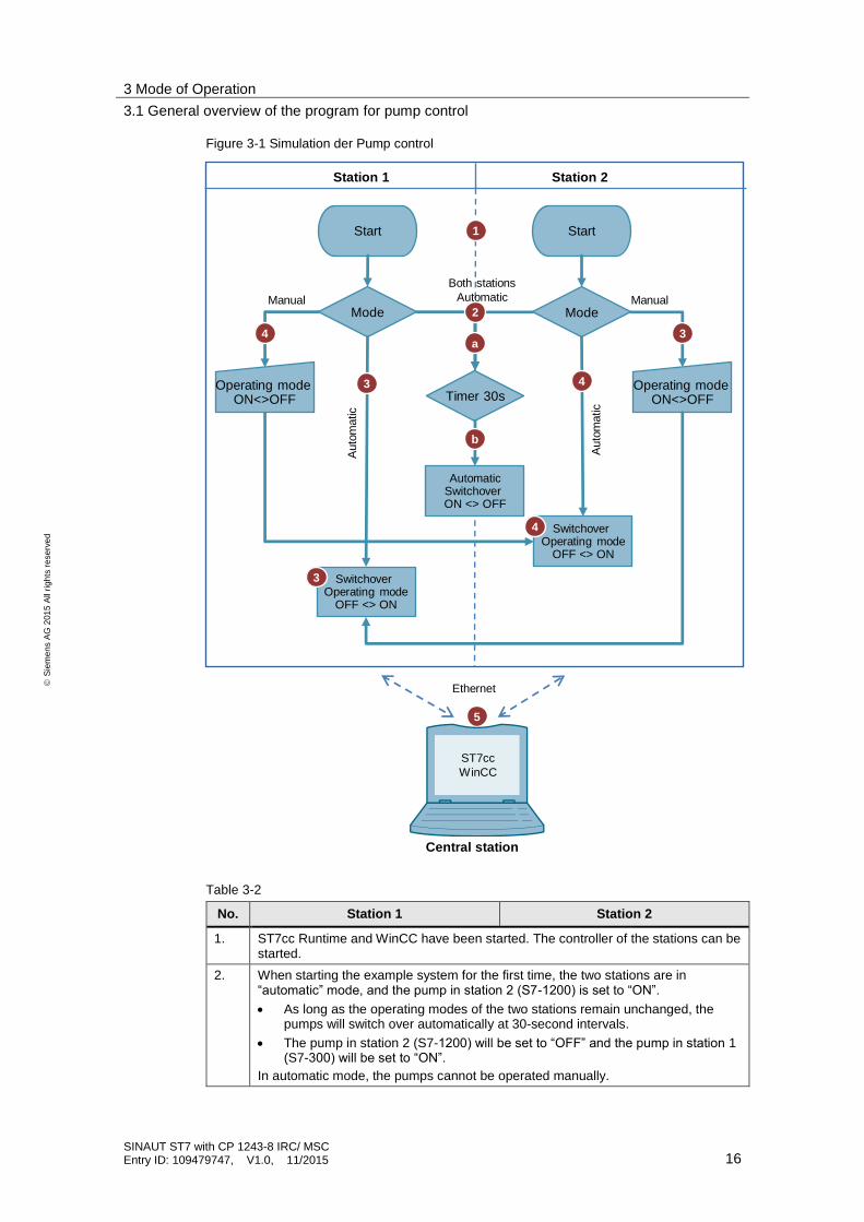
Figure 3-1 Simulation der Pump control
Start Start
Mode Mode
Timer 30s
AutomaticSwitchover ON <> OFF
Operating mode ON<>OFF
Switchover Operating mode
OFF <> ON
Switchover Operating mode
OFF <> ON
Manual Manual
Both stations
Automatic
Auto
matic
Auto
matic
Station 1 Station 2
Central station
Ethernet
1
2
3
a
b
4
4
5
Operating mode ON<>OFF
3
4
3
ST7cc
WinCC
Table 3-2
No. Station 1 Station 2
1. ST7cc Runtime and WinCC have been started. The controller of the stations can be started.
2. When starting the example system for the first time, the two stations are in “automatic” mode, and the pump in station 2 (S7-1200) is set to “ON”.
As long as the operating modes of the two stations remain unchanged, the pumps will switch over automatically at 30-second intervals.
The pump in station 2 (S7-1200) will be set to “OFF” and the pump in station 1 (S7-300) will be set to “ON”.
In automatic mode, the pumps cannot be operated manually.

3 Mode of Operation
3.1 General overview of the program for pump control
SINAUT ST7 with CP 1243-8 IRC/ MSC Entry ID: 109479747, V1.0, 11/2015 17
S
iem
en
s A
G 2
01
5 A
ll ri
gh
ts r
ese
rve
d
No. Station 1 Station 2
3. If the pump of station 1 (S7-300) is active and the pump of station 2 (S7-1200) turned “ON” / “OFF” manually, the pump of station 1 (S7-300) will be automatically switched “OFF” / “ON”.
4. If the pump of station 2 (S7-1200) is active and the pump of station 1 (S7-300) turned “ON” / “OFF” manually, the pump of station 2 (S7-1200) will be switched “OFF” / “ON” automatically.
5. Any data is stored in the central station and displayed in WinCC.
Program overview station 1/ station 2
The program structure for both stations is identical. The figure below shows the most important elements.
Figure 3-2
MainSet_p
Pump
DATA
IDB_Set_
Pump
Data
points
Station 1 > TD7onTIM
Station 2 > CP 1243-8 IRCUser block Data blocks
Table 3-3
Element Symbolic name Description
OB1 Main Cyclic OB: Calling the user program
FB2 / FB1 Set_Pump FB “Set_Pump” contains the described functions (chapter 3.1) fully implemented already.
DB2 IDB_Set_Pump Instance data block of the user block
DB1 Data Global data block for saving the data
Data points Configured data points for the data exchange between both stations or between a station and the central station (see Table 4-10 and Table 4-14)

3 Mode of Operation
3.1 General overview of the program for pump control
SINAUT ST7 with CP 1243-8 IRC/ MSC Entry ID: 109479747, V1.0, 11/2015 18
S
iem
en
s A
G 2
01
5 A
ll ri
gh
ts r
ese
rve
d
Global data block “Data” (DB1)
DB “Data” contains send data and receive data to/from the partner station. The structure of the global data block is identical for both stations.
Figure 3-3 Station 1_Global data block
Figure 3-4 Station 2_Global data block

3 Mode of Operation
3.1 General overview of the program for pump control
SINAUT ST7 with CP 1243-8 IRC/ MSC Entry ID: 109479747, V1.0, 11/2015 19
S
iem
en
s A
G 2
01
5 A
ll ri
gh
ts r
ese
rve
d
Table 3-4
Name Data type Description
OperatingStatus INT Operating state of the station
“1”: switched off
“2”: switched on
This tag is not a monitoring tag. It is only used by FB “Set_Pump”.
OperatingMode BOOL Operating mode of the station
False: automatic
True : manual
PartnerOpStatus INT Operating state of the partner station
“1”: switched off
“2”: switched on
This tag is not a monitoring tag. It is only used by user block FB “Set_Pump”.
PartnerOpMode BOOL Operating mode of the partner station
False: automatic
True : manual
partnerStatus BOOL Operating state of the partner station
False: automatic
True : manual
This tag is only relevant for station 2; it is not a monitoring tag. It is only used by FB “Set_Pump”.
TimerOB1 TIME
These tags are used for calling FB “Set_Pump” in OB1
OperatingModeOB1 BOOL
OperatingStatusOB1 BOOL
DoneOB1 BOOL
BusyOB1 BOOL
ErrorOB1 BOOL
StatusOB1 DWORD

3 Mode of Operation
3.2 Functionality of station 1 (S7-300)
SINAUT ST7 with CP 1243-8 IRC/ MSC Entry ID: 109479747, V1.0, 11/2015 20
S
iem
en
s A
G 2
01
5 A
ll ri
gh
ts r
ese
rve
d
3.2 Functionality of station 1 (S7-300)
3.2.1 Program details for FB “Set_Pump” (FB2)
The following figure and table show the call interface of user block FB “Set_Pump” (FB2).
Figure 3-5
InOut
Output
Table 3-5
Name Data type Description
operatingMode BOOL Operating mode of the station
False: automatic
True : manual
operatingStatus BOOL Operating state of the station
False: off
True : on
done BOOL Indicates whether job processing was performed without any errors.
Only pending for one CPU cycle.
busy BOOL Displayed job processing for the block
True: block active
False: block passive
error BOOL An error has occurred while processing the block.
Only pending for one CPU cycle.
status DWORD Display of error number.
Only pending for one CPU cycle.

3 Mode of Operation
3.2 Functionality of station 1 (S7-300)
SINAUT ST7 with CP 1243-8 IRC/ MSC Entry ID: 109479747, V1.0, 11/2015 21
S
iem
en
s A
G 2
01
5 A
ll ri
gh
ts r
ese
rve
d
3.2.2 Calling FB “Set_Pump” (FB2) in OB1
FB “Set_Pump” (FB2) is called cyclically in OB1. The figure below shows the call. The input and output parameters are stored in global data block “Data”.
Figure 3-6

3 Mode of Operation
3.3 Functionality of station 2 (S7-1200)
SINAUT ST7 with CP 1243-8 IRC/ MSC Entry ID: 109479747, V1.0, 11/2015 22
S
iem
en
s A
G 2
01
5 A
ll ri
gh
ts r
ese
rve
d
3.3 Functionality of station 2 (S7-1200)
3.2.1 Program details for FB “Set_Pump” (FB1)
The following figure and table show the call interface of user block FB “Set_Pump” (FB1).
Figure 3-7
Input
InOut
Output
Table 3-6
Name Data type Description
timer TIME Time interval for automatic switchover of the operating status of the stations
operatingMode BOOL Operating mode of the station
False: automatic
True : manual
operatingStatus BOOL Operating state of the station
False: off
True : on
done BOOL Indicates whether job processing was performed without any errors.
Only pending for one CPU cycle.
busy BOOL Displayed job processing for the block
True: block active
False: block passive
error BOOL An error has occurred while processing the block.
Only pending for one CPU cycle.
status DWORD Display of error number.
Only pending for one CPU cycle.

3 Mode of Operation
3.4 Error and status display
SINAUT ST7 with CP 1243-8 IRC/ MSC Entry ID: 109479747, V1.0, 11/2015 23
S
iem
en
s A
G 2
01
5 A
ll ri
gh
ts r
ese
rve
d
3.3.1 Calling FB “Set_Pump” (FB1) in OB1
FB “Set_Pump” (FB1) is called cyclically in OB1. The figure below shows the call. The input and output parameters are stored in global data block “Data”.
Figure 3-8
3.4 Error and status display
For error diagnostics, the FB “Set_Pump” function block has a STATUS output.
The following table shows the error messages of the function block.
Table 3-7
STATUS Description Remedy
16#00008101 There is no connection to the partner station.
Check the connection between both stations.
16#00008102 There is no connection to the central station.
Check the connection between the station and the central station.
Start ST7cc Runtime.
16#00008103 There is no connection to partner station and central station.
Check the connection between both stations and between the stations and the central station.
Start ST7cc Runtime.

4 Configuration and Settings
4.1 Overview
SINAUT ST7 with CP 1243-8 IRC/ MSC Entry ID: 109479747, V1.0, 11/2015 24
S
iem
en
s A
G 2
01
5 A
ll ri
gh
ts r
ese
rve
d
4 Configuration and Settings
4.1 Overview
Note The configuration and settings are ready implemented in the project. This chapter is for information purposes only.
Since SINAUT ST7 is currently not yet supported in TIA Portal, the following two engineering tools are required for configuring CP 1243-8 IRC:
STEP 7 V5.5 and SINAUT engineering software V5.5 and
STEP7 V13 SP1 Support Package 0111.
Perform the configuration successively in the following configuration tools.
Note Handling the configuration tools is not discussed in this documentation. Basic knowledge of these tools is assumed.
Figure 4-1
STEP 7 V5.5
• Configuring the S7-300 station
• Configuring a CP proxy (PROXY CP
1243-8 IRC) for the S7-1200 station
• Configuring the central station (St7cc)
• Configuring the DSL station
• Configuring the GPRS station
SINAUT ST7 Engineering Tool
• Configuring the SINAUT connections
• Configuring the subscriber
administration
• Exporting the configuration data for CP
1243-8 IRC
STEP 7 V13
• Configuring the S7-1200 station
• Importing the configuration data (of
SINAUT ST7) for CP 1243-8 IRC
• Create data points
SINAUT ST7cc
• Integrating ST7cc into SINAUT network
• Create ST7cc project
• Configuring the data with ST7cc Config
• Generating the WinCC configuration for
ST7cc tags and their processing

4 Configuration and Settings
4.2 Configuration in STEP 7 V5.5
SINAUT ST7 with CP 1243-8 IRC/ MSC Entry ID: 109479747, V1.0, 11/2015 25
S
iem
en
s A
G 2
01
5 A
ll ri
gh
ts r
ese
rve
d
4.2 Configuration in STEP 7 V5.5
In STEP 7 V5.5, all of the stations as well as the S7 connections are configured. In addition, a proxy for the CP (PROXY CP1243-8 IRC) is configured in an S7-300 station.
4.2.1 Configuring the stations
Table 4-1
No. Action
1. In the SIMATIC Manager, you create a STEP 7 project and add an S7-300 station.
2. Open HW Config and add any S7-300 controller with TIM 3V-IE Advanced.
3. Add any second S7-300 station.
4. In the second station, you enter the “proxy” as a representative for the CP.
You find the module in the catalog of HW Config under the name
"PROXY CP1243-8 IRC".
Configure the proxy like TIM 3V-IE Advanced.
5. In the SIMATIC Manager you enter a SIMATIC PC station.
6. Specify the hardware configuration of the PC station:
Slot 1: Application
Slot 4: CP Industrial Ethernet (IE General).
7. Add a master TIM 4R-IE to your network configuration.
8. Open NetPro. Add two new Ethernet networks and assign the desired IP addresses to the modules (see Table 5-1).
9. Connect interface X4 of TIM 4R-IE with the St7cc central station.
Note Interface X3 of TIM4R-IE must be configured for the MSC network.

4 Configuration and Settings
4.2 Configuration in STEP 7 V5.5
SINAUT ST7 with CP 1243-8 IRC/ MSC Entry ID: 109479747, V1.0, 11/2015 26
S
iem
en
s A
G 2
01
5 A
ll ri
gh
ts r
ese
rve
d
4.2.2 Configuring the ST7cc central station
The IP address of the central station is set as in Table 5-1. The value for the parameter “Send Keepalives for Connections” of the Ethernet interface in the central station must coincide with the value of this parameter in the master TIM. It is set to 10 seconds for this reason.
Double click on IE General in St7cc to open the Properties of IE General and go to the Options tab.
Figure 4-2
4.2.3 Configuration of the TIM 4R-IE in the central station
The following table shows the settings for the master TIM so it is used as an MSC master.
The first Ethernet interface of TIM4R-IE will be used for the MSC network. The second Ethernet interface is used for the local connection to the ST7cc central station.
Table 4-2
No. Action
1. Open the Properties of TIM 4R-IE by double clicking on the TIM, and go to the Interfaces tab.
2. Select the interface Ethernet 1.

4 Configuration and Settings
4.2 Configuration in STEP 7 V5.5
SINAUT ST7 with CP 1243-8 IRC/ MSC Entry ID: 109479747, V1.0, 11/2015 27
S
iem
en
s A
G 2
01
5 A
ll ri
gh
ts r
ese
rve
d
No. Action
3. Click on Properties to configure it:
IP address: 172.16.62.10
Subnet mask: 255.255.0.0
Router: 172.16.0.1 (internal IP address of your router)
4. Click on OK to confirm the settings.
5. With this parameter, you set the TCP/ IP keepalive interval of the TIM for the MSC network.
Note:
The recommended setting for GPRS connections is 120 sec. Since in this example, there is a connection to a GPRS station, this value has to be set to 120 seconds at the master TIM (MSC master).

4 Configuration and Settings
4.2 Configuration in STEP 7 V5.5
SINAUT ST7 with CP 1243-8 IRC/ MSC Entry ID: 109479747, V1.0, 11/2015 28
S
iem
en
s A
G 2
01
5 A
ll ri
gh
ts r
ese
rve
d
No. Action
6. Set the Ethernet timeout for sending message frames.
Note:
Usually, a send frame in the EGPRS/GPRS network is acknowledged within 1-2 seconds. At high network loads this may take longer. In practice, a value of 10 seconds has proven successful.
7. Configure the interface in the central station as MSC master.
8. Close the dialog box with OK.

4 Configuration and Settings
4.2 Configuration in STEP 7 V5.5
SINAUT ST7 with CP 1243-8 IRC/ MSC Entry ID: 109479747, V1.0, 11/2015 29
S
iem
en
s A
G 2
01
5 A
ll ri
gh
ts r
ese
rve
d
No. Action
9. Go to the “Time service” tab and configure the clock synchronization.
Close the dialog box with OK.
Note:
Ethernet 1: The master TIM is configured as synchronization master.
Ethernet 2: ST7cc is the synchronization master.
4.2.4 Configuring the DSL station (S7-300 station)
The following table shows the settings for the TIM 3V-IE so it is used as MSC station.
Table 4-3
No. Action
1. Open the Properties of TIM 3V-IE by double clicking on the TIM, and go to the Interfaces tab.
2. Select the interface Ethernet 1.

4 Configuration and Settings
4.2 Configuration in STEP 7 V5.5
SINAUT ST7 with CP 1243-8 IRC/ MSC Entry ID: 109479747, V1.0, 11/2015 30
S
iem
en
s A
G 2
01
5 A
ll ri
gh
ts r
ese
rve
d
No. Action
3. Click on Properties to configure it:
IP address: 192.168.2.90
Subnet mask: 255.255.255.0
Router: 192.168.2.1 (internal IP address of your router)
4. Click on OK to confirm the settings.
5. With this parameter, you set the TCP/ IP keepalive interval of the TIM for the MSC network.
Note:
The recommended setting for GPRS connections is 120 sec. Since in this example, there is a connection to a GPRS station, this value has to be set to 120

4 Configuration and Settings
4.2 Configuration in STEP 7 V5.5
SINAUT ST7 with CP 1243-8 IRC/ MSC Entry ID: 109479747, V1.0, 11/2015 31
S
iem
en
s A
G 2
01
5 A
ll ri
gh
ts r
ese
rve
d
No. Action
seconds at the TIM (MSC station).
6. Set the Ethernet timeout for sending message frames.
Note:
Usually, a send frame in the EGPRS/GPRS network is acknowledged within 1-2 seconds. At high network loads this may take longer. In practice, a value of 10 seconds has proven successful.
7. Configure the interface in station 1 as MSC station.
8. Close the dialog box with OK.
9. Go to the “Time service” tab and configure the clock synchronization.
Close the dialog box with OK.
Note:
For this station the master TIM 4R-IE is the synchronization master.

4 Configuration and Settings
4.2 Configuration in STEP 7 V5.5
SINAUT ST7 with CP 1243-8 IRC/ MSC Entry ID: 109479747, V1.0, 11/2015 32
S
iem
en
s A
G 2
01
5 A
ll ri
gh
ts r
ese
rve
d
4.2.5 Configuring the GPRS station (S7-1200 station)
The following table shows the settings for CP 1243-8 IRC, so it is used as GPRS station.
Table 4-4
No. Action
1. Open the Properties of CP 1243-8 IRC by double clicking on the CP and go to the Interfaces tab.
2. Select the WAN 1 interface and set Ethernet as the WAN network.
3. Click on the New button and then on Properties.

4 Configuration and Settings
4.2 Configuration in STEP 7 V5.5
SINAUT ST7 with CP 1243-8 IRC/ MSC Entry ID: 109479747, V1.0, 11/2015 33
S
iem
en
s A
G 2
01
5 A
ll ri
gh
ts r
ese
rve
d
No. Action
4. Enter an IP address for the CP.
Select the subnet MSC network and close the window with OK.
Note:
You can select the IP address for the CP freely. However, it mustn’t exist in the project already, and it should be located in a different IP subnet.
5. Configure the interface in station 2 as MSC station.

4 Configuration and Settings
4.2 Configuration in STEP 7 V5.5
SINAUT ST7 with CP 1243-8 IRC/ MSC Entry ID: 109479747, V1.0, 11/2015 34
S
iem
en
s A
G 2
01
5 A
ll ri
gh
ts r
ese
rve
d
No. Action
6. Close the dialog box with OK.
7. Go to the “Time service” tab and configure the clock synchronization.
Close the dialog box with OK.
Note:
For this station the master TIM 4R-IE is the synchronization master.
8. Save and compile the changes in NetPro.

4 Configuration and Settings
4.3 Configuration with the SINAUT ST7 configuration tool
SINAUT ST7 with CP 1243-8 IRC/ MSC Entry ID: 109479747, V1.0, 11/2015 35
S
iem
en
s A
G 2
01
5 A
ll ri
gh
ts r
ese
rve
d
4.3 Configuration with the SINAUT ST7 configuration tool
The SINAUT ST7 configuration software represents the user interface for the configuration of SINAUT telecontrol systems. Using this software helps the user install and configure the telecontrol components into a STEP 7 project.
Apart from this, the SINAUT ST7 software makes the following configuration possible
SINAUT networks and WAN network nodes,
SINAUT TIM modules and
SINAUT connections.
Before starting with the configuration, you need to import the PC station (see chapter 5.4.5).
4.3.1 Connection configuration and provider settings
Table 4-5
No. Action
1. Start the SINAUT ST7 configuration tool.
“Start > Siemens automation > SIMATIC > SINAUT ST7 > Configuration”
2. Open the STEP 7 project created in chapter 4.2.
3. Select Connection Configuration and click on the OK button to start.
4 Configuration and Settings
4.3 Configuration with the SINAUT ST7 configuration tool
SINAUT ST7 with CP 1243-8 IRC/ MSC Entry ID: 109479747, V1.0, 11/2015 36
S
iem
en
s A
G 2
01
5 A
ll ri
gh
ts r
ese
rve
d
No. Action
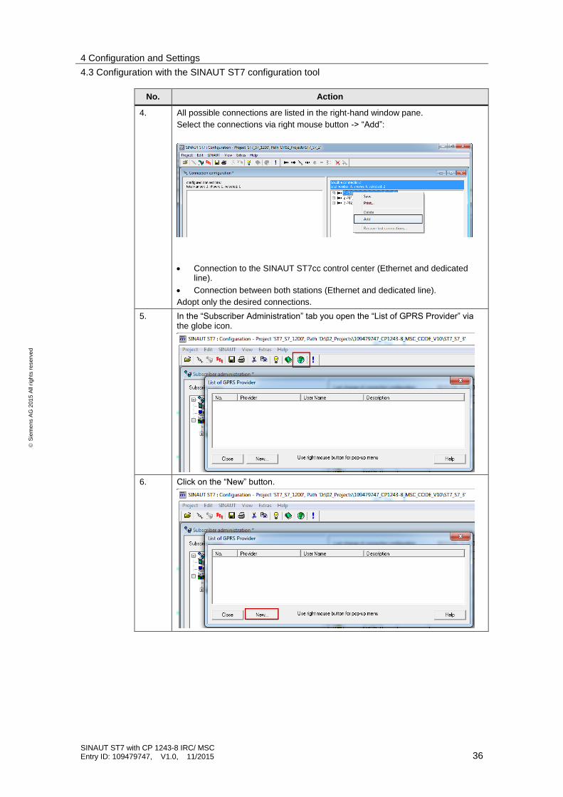
4. All possible connections are listed in the right-hand window pane.
Select the connections via right mouse button -> “Add”:
Connection to the SINAUT ST7cc control center (Ethernet and dedicated line).
Connection between both stations (Ethernet and dedicated line).
Adopt only the desired connections.
5. In the “Subscriber Administration” tab you open the “List of GPRS Provider” via the globe icon.
6. Click on the “New” button.

4 Configuration and Settings
4.3 Configuration with the SINAUT ST7 configuration tool
SINAUT ST7 with CP 1243-8 IRC/ MSC Entry ID: 109479747, V1.0, 11/2015 37
S
iem
en
s A
G 2
01
5 A
ll ri
gh
ts r
ese
rve
d
No. Action
7. Enter the properties of your provider.
The information for Access Point Name, Username and Password will be provided by your GPRS provider.
Close the window with OK.
8. Your provider has been entered in the list of GPRS providers.
Close the window with Close.
4.3.2 MSC settings
Entering the IP address of the DSL router in the central station
Table 4-6
No. Action
1. In the “Subscriber Administration” you open the properties dialog of the master TIM by double clicking on the master TIM.

4 Configuration and Settings
4.3 Configuration with the SINAUT ST7 configuration tool
SINAUT ST7 with CP 1243-8 IRC/ MSC Entry ID: 109479747, V1.0, 11/2015 38
S
iem
en
s A
G 2
01
5 A
ll ri
gh
ts r
ese
rve
d
No. Action
2. Click on the “MSC Master properties” button.
3. Enter the fixed IP address of the DSL router allocated by the provider.
Close the window with OK.
Note If you do not have a fixed IP address, you use the fields “Name of the Internet Router” and “IP address of DNS Server” in step 2.

4 Configuration and Settings
4.3 Configuration with the SINAUT ST7 configuration tool
SINAUT ST7 with CP 1243-8 IRC/ MSC Entry ID: 109479747, V1.0, 11/2015 39
S
iem
en
s A
G 2
01
5 A
ll ri
gh
ts r
ese
rve
d
Settings of the DSL station (S7-300 station)
Table 4-7
No. Action
1. Double-click the DSL station.
2. The window with the MSC station properties opens.
Enter a user name and password for the MSC login, and close the window with OK.
Note The MSC user name must be unique in the project.

4 Configuration and Settings
4.3 Configuration with the SINAUT ST7 configuration tool
SINAUT ST7 with CP 1243-8 IRC/ MSC Entry ID: 109479747, V1.0, 11/2015 40
S
iem
en
s A
G 2
01
5 A
ll ri
gh
ts r
ese
rve
d
Settings of the GPRS station (S7-1200 station)
Table 4-8
No. Action
1. Double-click the GPRS station.
2. The window with the MSC station properties opens.
Enter the PIN of your SIM card.
Then enter a user name and password for the MSC login and close the window with OK.

4 Configuration and Settings
4.3 Configuration with the SINAUT ST7 configuration tool
SINAUT ST7 with CP 1243-8 IRC/ MSC Entry ID: 109479747, V1.0, 11/2015 41
S
iem
en
s A
G 2
01
5 A
ll ri
gh
ts r
ese
rve
d
No. Action
3. The globes of the MSC stations are displayed in color.
That is, all required settings have been made.
Close the window with OK.
4. Save and compile your project.
Save the configuration in NetPro again.
Note The MSC user name must be unique in the project.

4 Configuration and Settings
4.3 Configuration with the SINAUT ST7 configuration tool
SINAUT ST7 with CP 1243-8 IRC/ MSC Entry ID: 109479747, V1.0, 11/2015 42
S
iem
en
s A
G 2
01
5 A
ll ri
gh
ts r
ese
rve
d
4.3.3 Configuration of the TIMs with TD7onTIM
The SINAUT communication of CPU modules with each other, or of CPU modules with a control center is realized with the help of TIM modules. The organization of
the SINAUT communication is handled by the SINAUT TD7 software package. In
SINAUT station S7-300, the TD7 software is configured on the TIM.
Note This configuration is not required for the proxy module of CP 1243-8 IRC. The configuration data for CP 1243-8 IRC is imported into STEP 7 V13 via a text file (see chapter 4.4).
Table 4-9
No. Action
1. In the “Subscriber Administration” tab, all SINAUT subscribers (CPUs, TIMs, CP 1243-8 IRC, SINAUT ST7cc PC) are listed.
You can enter any not yet assigned subscriber number according to your desires.
.
2. In Subscriber Administration, the TD7onTIM stations are configured. Select the TIM 3V-IE.

4 Configuration and Settings
4.3 Configuration with the SINAUT ST7 configuration tool
SINAUT ST7 with CP 1243-8 IRC/ MSC Entry ID: 109479747, V1.0, 11/2015 43
S
iem
en
s A
G 2
01
5 A
ll ri
gh
ts r
ese
rve
d
No. Action
3. Click on the TD7onTIM library icon.
A window with the TD7onTIM Library opens.
Select the object you wish to configure (Bin08X_R) and click on “Paste into Project”.
Click the Close button to close the library.
4. Define the parameters for the objects.
If you select the DB as memory area, you need to create a data block with the required tags in the S7-300 CPU.

4 Configuration and Settings
4.3 Configuration with the SINAUT ST7 configuration tool
SINAUT ST7 with CP 1243-8 IRC/ MSC Entry ID: 109479747, V1.0, 11/2015 44
S
iem
en
s A
G 2
01
5 A
ll ri
gh
ts r
ese
rve
d
No. Action
5. Select the communication partner for the respective data object.
Note:
All partners must be added to the “Selected partners” list from which the data of the object shall be received or sent to. If no partner is adopted in the “Selected partners” list, the object will not be processed.
6. Enter your own source object number and the partner object number.
The configuration tool specifies a value with continuous numbering that can be changed. Inconsistent double assignment of numbers is blocked.
Note:
In these input fields, the data object is assigned to the respective partner object of the selected communication partner.
For objects from/to ST7CC/SC, the partner object number is always 0.
7. Uncheck all send parameters.
8. Then save and compile your project.

4 Configuration and Settings
4.3 Configuration with the SINAUT ST7 configuration tool
SINAUT ST7 with CP 1243-8 IRC/ MSC Entry ID: 109479747, V1.0, 11/2015 45
S
iem
en
s A
G 2
01
5 A
ll ri
gh
ts r
ese
rve
d
No. Action
9. Confirm the security prompt with OK, leave the options settings unchanged and click the OK button.
10. The SDBs are generated anew and saved in the STEP 7 project.
If no errors have occurred, close the program again.
11. Load the configuration into the TIM 3V-IE:
Open the SIMATIC Manager
Select the “Blocks” folder TIM-3V-IE of the S7-300 station
Load the system data into the TIM 3V-IE.
Then load the S7-300 station.

4 Configuration and Settings
4.3 Configuration with the SINAUT ST7 configuration tool
SINAUT ST7 with CP 1243-8 IRC/ MSC Entry ID: 109479747, V1.0, 11/2015 46
S
iem
en
s A
G 2
01
5 A
ll ri
gh
ts r
ese
rve
d
Configured SINAUT objects
The transmission and receipt of process data is configured with the help of standardized data objects. The following table describes the SINAUT objects configured for this example.
Table 4-10
Object object number
Partner
Object
Explanation
Bin08X_S 1 1_ Bin08X_R Sending the operating mode to S7-1200
Ana04W_R 2 3_ Ana04W_S Receiving partner operating status
Ana04W_S 3 4_Ana04W_R Sending operating status to S7-1200
Cmd01B_R 4 0_Cmd01B_R Receiving command from the ST7cc
Bin04B_S 5 0_ Bin04B_S Sending the operating mode to St7cc
Bin08X_R 6 2_Bin08X_S Receiving partner operating mode
Bin08X_S 7 7_Bin08X_R Sending operating status to S7-1200
4.3.4 Exporting configuration data
After completing the configuration of the proxy in STEP 7 V5.5 and in the SINAUT configuration tool, the specific configuration data for the telecontrol communication of the proxy as well as for the TIM modules is stored in the system blocks (SDBs).
Table 4-11
No. Action
1. In the SINAUT ST7 configuration tool you open the SINAUT diagnostics and service tool.
2. Select the proxy.

4 Configuration and Settings
4.3 Configuration with the SINAUT ST7 configuration tool
SINAUT ST7 with CP 1243-8 IRC/ MSC Entry ID: 109479747, V1.0, 11/2015 47
S
iem
en
s A
G 2
01
5 A
ll ri
gh
ts r
ese
rve
d
No. Action
3. Right click to open the “SINAUT > SDB viewer” menu.
4. Save the file.
Close the dialog.

4 Configuration and Settings
4.4 Configuring in STEP 7 V13
SINAUT ST7 with CP 1243-8 IRC/ MSC Entry ID: 109479747, V1.0, 11/2015 48
S
iem
en
s A
G 2
01
5 A
ll ri
gh
ts r
ese
rve
d
4.4 Configuring in STEP 7 V13
In STEP 7 V13, the S7-1200 station is configured:
import the configuration data
configuring the data points of the CP 1243-8 IRC.
Prerequisite for the complete configuration of the CP in STEP 7 V13 is the configuration in STEP 7 V5.5 (see chapter 4.2) and the configuration with the SINAUT ST7 configuration tool (see chapter 4.3)
4.4.1 Configuring the parameters of CP 1243-8 IRC
Table 4-12
No. Action
1. Create a STEP 7 V13 project.
2. Add the S7-1200 CPU (as of V4.1) for the SIMATIC station.
3. Add the CP 1243-8 into the station.
4. Create an Ethernet network and connect the CP to the Ethernet network.
5. Enable the telecontrol and S7 communication:
“Properties > Communication types”

4 Configuration and Settings
4.4 Configuring in STEP 7 V13
SINAUT ST7 with CP 1243-8 IRC/ MSC Entry ID: 109479747, V1.0, 11/2015 49
S
iem
en
s A
G 2
01
5 A
ll ri
gh
ts r
ese
rve
d
No. Action
6. For the CP, you import the configuration data from the
STEP 7 V5 project via the text file:
In your STEP 7 V13 project you select CP 1243-8 IRC.
Select the parameter group “Partner stations”.
Click on the “Import partner configuration” button.
From the file system of the engineering station, you select the text file you exported from the CP proxy of the SINAUT ST7 project (see chapter 4.3.4).
7. Enable the security functions.
Create a user for the security functions.
“Properties > Security > Security properties”
8. Load the project data into the station.
Note:
When loading the station, the project data of the station is stored on the CPU, including the configuration data of the CP.

4 Configuration and Settings
4.4 Configuring in STEP 7 V13
SINAUT ST7 with CP 1243-8 IRC/ MSC Entry ID: 109479747, V1.0, 11/2015 50
S
iem
en
s A
G 2
01
5 A
ll ri
gh
ts r
ese
rve
d
4.4.2 Configuring the data points of CP 1243-8 IRC
The transmission of user data between the S7-1200 CPU and your communication partner does not require the programming of program blocks for the CP. The data areas in the memory of the CPU intended for the communication with the partner, are configured data-point-related in the CP. Any data point is linked to a PLC tag or a data block in the CPU here.
Table 4-13
No. Action
1. In the CPU, you create a data block with the required PLC tags for the data points.
2. In STEP 7 you open the editor for data point configuration and message configuration
ST7_S7_1200 > PLC_1 > Local modules > CP 1243-8 IRC.
3. Create the data points of the CP.
4. For each data type you select the transmission type.
“Transfer after call”
The respective most current value of the data point is only entered into the picture memory of the CP. New values of a data point overwrite the last saved value in the picture memory.

4 Configuration and Settings
4.4 Configuring in STEP 7 V13
SINAUT ST7 with CP 1243-8 IRC/ MSC Entry ID: 109479747, V1.0, 11/2015 51
S
iem
en
s A
G 2
01
5 A
ll ri
gh
ts r
ese
rve
d
No. Action
“Every value triggered”
The data point is configured as event.
Each value change is entered into the send buffer in chronological order.
“Current value triggered”:
The data point is configured as event.
Only the respectively last current value is entered into the send buffer. There, it overwrites the previously stored value.
5. For each data type you configure the trigger conditions.
Select “Direct Transfer” as the transfer mode.
6. Assign the data object to the respective partner object.
7. Select the communication partner for the respective data object.
8. Save and load the changes.
Configured data types
Table 4-14
Object object number
Partner
Object
Explanation
Bin08X_R 1 1_Bin08X_S Receiving the partner operating mode
Bin08X_S 2 6_Bin08X_R Sending the operating mode to S7-300
Ana04W_S 3 2_Ana04W_R Sending the operating status to S7-300
Ana04W_R 4 3_ Ana04W_S Receiving partner operating status
Cmd01B_R 5 0_ Cmd01B_R Receiving a command from the ST7cc
Bin04B_S 6 6_Bin04B_S Sending the operating status to St7cc

4 Configuration and Settings
4.4 Configuring in STEP 7 V13
SINAUT ST7 with CP 1243-8 IRC/ MSC Entry ID: 109479747, V1.0, 11/2015 52
S
iem
en
s A
G 2
01
5 A
ll ri
gh
ts r
ese
rve
d
Object object number
Partner
Object
Explanation
Bin04B_S 6 6_Bin04B_S Sending the operating mode to St7cc
Bin08X_R 7 7_Bin08X_S Receiving the status of the S7-1200 station

4 Configuration and Settings
4.5 Configuration of ST7cc
SINAUT ST7 with CP 1243-8 IRC/ MSC Entry ID: 109479747, V1.0, 11/2015 53
S
iem
en
s A
G 2
01
5 A
ll ri
gh
ts r
ese
rve
d
4.5 Configuration of ST7cc
SINAUT ST7cc is the ideal control center system for SINAUT ST7 based on SIMATIC WinCC. It is specifically adjusted to the event-controlled and time-stamped data transmission of the SINAUT system.
In combination with the WinCC redundancy package, a highly available ST7cc control center can be realized.
SINAUT ST7cc provides the following benefits to the user:
Connecting SINAUT stations to SIMATIC WinCC via classic, serial WAN or via Ethernet-based WAN
Entering messages, analog values, and count values into WinCC archives using the event times supplied by the SINAUT stations
Time saving and cost reduction due to simple configuration without detailed knowledge of SINAUT
The table below lists the steps necessary for configuring the St7cc.
Table 4-15
No. Action
9. Open the SINAUT ST7cc Config.
10. Add a local TIM for the St7cc PC.
“Edit > New local TIM”
Enter the SINAUT subscriber number of the TIM.
11. Add the stations with their subscriber number.
“Edit > New Station”
12. Add the desired objects by copying them from the library. Configure the objects as desired.
13. Open the global settings.

4 Configuration and Settings
4.5 Configuration of ST7cc
SINAUT ST7 with CP 1243-8 IRC/ MSC Entry ID: 109479747, V1.0, 11/2015 54
S
iem
en
s A
G 2
01
5 A
ll ri
gh
ts r
ese
rve
d
No. Action
“Edit > Global Settings”.
In the “Computer” tab, you enter the name and IP address of the ST7cc PC, and enter the server settings in System.
14. Go to the “Project” tab and activate it for the St7cc Runtime.
15. Open the project settings mask.
“Edit > Project Settings”.

4 Configuration and Settings
4.5 Configuration of ST7cc
SINAUT ST7 with CP 1243-8 IRC/ MSC Entry ID: 109479747, V1.0, 11/2015 55
S
iem
en
s A
G 2
01
5 A
ll ri
gh
ts r
ese
rve
d
No. Action
Go to the “Communication” tab.
Enter the subscriber number of the ST7cc PC.
Then, click on “New” and enter the subscriber number of the local TIM and the local ID for the connection between TIM and ST7cc PC.
Click on OK to confirm the settings.
Note:
The local ID is available in NetPro. Click on the PC-Station and then on Application. The ID is displayed in the bottom window.
The access point must be created in the PG/PG station settings and assigned to the Ethernet adapter used:
> "Adaptername".TCP.

4 Configuration and Settings
4.5 Configuration of ST7cc
SINAUT ST7 with CP 1243-8 IRC/ MSC Entry ID: 109479747, V1.0, 11/2015 56
S
iem
en
s A
G 2
01
5 A
ll ri
gh
ts r
ese
rve
d
No. Action
16. Save the ST7cc project.
Configured ST7cc objects
Table 4-16
Object object
number
Partner Explanation
Cmd01B_R 4 Station 1 (subscriber 2)
Setting/ resetting OperatingMode and OperatingStatus of station 1
Bin04B_S 5 Station 1
(Subscriber 2)
Receiving OperatingMode and OperatingStatus of station 1
Cmd01B_R 5 Station 2
(Subscriber 3)
Setting/ resetting OperatingMode and OperatingStatus of station 2
Bin04B_S 6 Station 2
(Subscriber 3)
Receiving OperatingMode and OperatingStatus of station 2

4 Configuration and Settings
4.6 WinCC generation
SINAUT ST7 with CP 1243-8 IRC/ MSC Entry ID: 109479747, V1.0, 11/2015 57
S
iem
en
s A
G 2
01
5 A
ll ri
gh
ts r
ese
rve
d
4.6 WinCC generation
The parameters of processes executed in WinCC are transferred to the WinCC target component via the ODK interface. St7cc Config supports the following generation options:
WinCC generation:
– WinCC tag management
– WinCC messages
– WinCC archive tags
Generating the subscriber picture typicals.
Requirements for the generation
Prior to generating tags, messages, or archives, please ensure that the following requirements have been met:
The project in which you wish to generate is set as current WinCC project in configuration mode (must not be in runtime mode).
The standard language of the project is activated.
The channel DLL for the ST7 server (ST7.DLL) is declared in the project.
The messages classes and messages types for system tags and user tags are created in WinCC.
The user archives are created in WinCC.
At the first generation sequence, St7cc Config logs in at all WinCC components. Logout is only performed when closing the generation dialog.
Note More information on working with WinCC is available in manual “WinCC 7.3: Working with WinCC” (see \8\)
WinCC generation
The following table shows how all of the required configuration data of ST7cc is transferred in WinCC.
Table 4-17
No. Action
1. Open the SINAUT ST7cc Config.
2. Open your ST7cc project (see Table 4-15).
3. Insert the picture typicals and the faceplates into process pictures:
“Admin > Copy Faceplates to WinCC Project > WinCC Project > open .mcp data”.

4 Configuration and Settings
4.6 WinCC generation
SINAUT ST7 with CP 1243-8 IRC/ MSC Entry ID: 109479747, V1.0, 11/2015 58
S
iem
en
s A
G 2
01
5 A
ll ri
gh
ts r
ese
rve
d
No. Action
4. Insert the subscriber picture typicals into a process picture:
“EDIT > create the Project picture-typicals”.
5. Insert the technical picture typicals into a process picture:
“Edit > create the technical picture-typicals”.
5 Installation and Commissioning
5.1 Installing the hardware
SINAUT ST7 with CP 1243-8 IRC/ MSC Entry ID: 109479747, V1.0, 11/2015 59
S
iem
en
s A
G 2
01
5 A
ll ri
gh
ts r
ese
rve
d
5 Installation and Commissioning This chapter contains all steps necessary for commissioning the example with the code from the download and the hardware list.
5.1 Installing the hardware
For the necessary hardware components, please refer to chapter 2.4.
Note Always follow the installation guidelines for all components.
NOTICE Before switching on the power supply, you need to complete and check the installation!
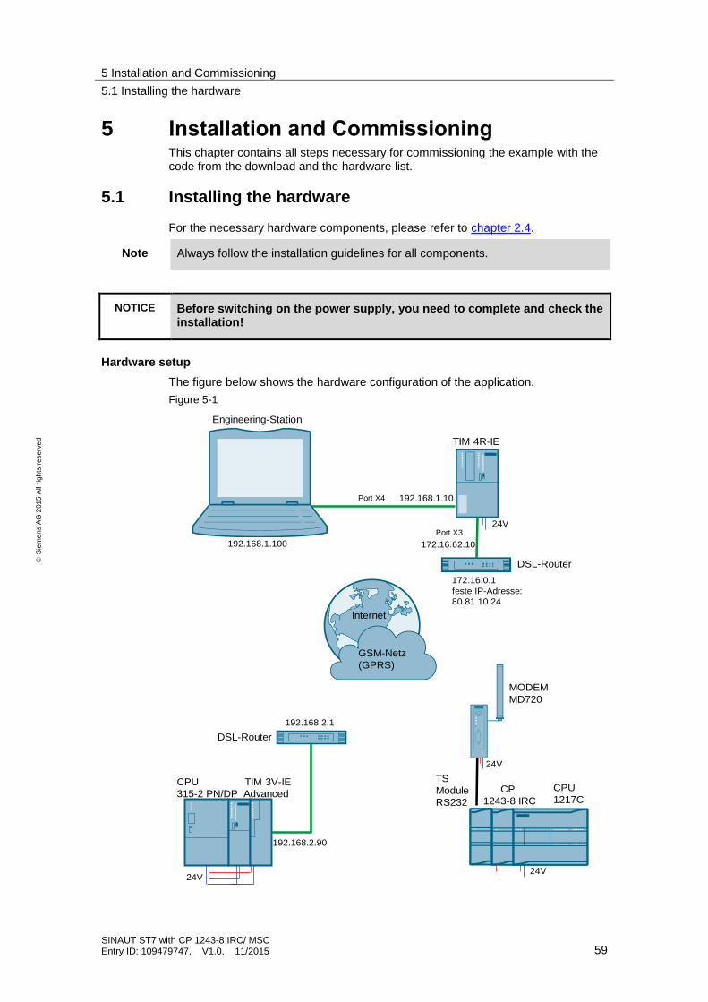
Hardware setup
The figure below shows the hardware configuration of the application.
Figure 5-1
TIM 4R-IE
Engineering-Station
CPU TIM 3V-IE
315-2 PN/DP Advanced
24V24V
24V
CP
1243-8 IRC
Port X4
Port X3
TS
Module
RS232
CPU
1217C
24V
MODEM
MD720
DSL-Router
192.168.2.1
192.168.2.90
172.16.0.1
feste IP-Adresse:
80.81.10.24
172.16.62.10192.168.1.100
192.168.1.10
GSM-Netz
(GPRS)
Internet
DSL-Router

5 Installation and Commissioning
5.1 Installing the hardware
SINAUT ST7 with CP 1243-8 IRC/ MSC Entry ID: 109479747, V1.0, 11/2015 60
S
iem
en
s A
G 2
01
5 A
ll ri
gh
ts r
ese
rve
d
The following table contains the overview of all IP addresses and SINAUT subscriber numbers used in this example.
Table 5-1
Component IP address SINAUT subscriber
number
Description
ST7cc computer 192.168.1.100 1 Central station
Subnet mask:
255.255.255.0.
TIM 4R-IE 192.168.1.10
1003
Master TIM, Ethernet Port X4
Subnet mask:
255.255.255.0.
TIM 4R-IE 172.16.62.10 Master TIM, Ethernet Port X3
Subnet mask:
255.255.0.0.
Central station DSL router
172.16.0.1
Subnet mask:
255.255.0.0
Fixed IP address of your provider:
CPU1217C (proxy CPU317-2 PN/DP)
192.168.0.1 3 Station 2
Subnet mask:
255.255.255.0.
CP 1243-8 IRC 172.16.62.2 1001 CP in station 2
Subnet mask:
255.255.0.0.
You can select the IP address freely. However, it mustn’t exist in the project already, and it should be located in a different IP subnet.
CPU315-2 PN/DP 192.168.0.2 2 Station 1
Subnet mask:
255.255.255.0.
TIM 3V-IE Advanced
192.168.2.90 1002 TIM in station 1
Subnet mask:
255.255.255.0.
DSL router Station1 192.168.2.1 Subnet mask:
255.255.255.0
Note The only interface which can be configured for an MSC network is the X3 interface of TIM4R-IE.

5 Installation and Commissioning
5.1 Installing the hardware
SINAUT ST7 with CP 1243-8 IRC/ MSC Entry ID: 109479747, V1.0, 11/2015 61
S
iem
en
s A
G 2
01
5 A
ll ri
gh
ts r
ese
rve
d
5.1.1 Installing the hardware
For setting up the hardware, please proceed according to the following table:
Table 5-2
No. Action Notes
1. Connect engineering station Connect computer to port X4 of TIM 4R-IE
2. Mount the voltage supply Connect the PS307 to the power grid (220 / 230 V AC).
The SIMATIC PS307 can supply all the modules required here.
3. Install TIM 4R-IE Connect the power supply
Connect computer to port X4 of TIM 4R-IE
Connect computer with port X3 of the TIM4R-IE.
4. Install CPU315-2 PN/DP Adjust backplane bus adapter for TIM
Connect the power supply
Plug the MMC
5. Install TIM 3V-IE Advanced Connect the power supply
Connect TIM and CPU315-2 PN/DP via backplane bus connector
Connect DSL router with TIM 3V-IE via your Ethernet interface.
6. Install CPU 1217C DC/DC/DC Connect the power supply
Plug in the MC
7. Install CP 1243-8 IRC Connect CP and CPU 1217C (links of the CPU)
Connect the external power supply
8. TS module RS232 Connect TS module RS232 and CP (links of the CP)
9. Modem MD720 Create SIM card
Connect antenna
Connect the power supply
Connect MD720 and TS module RS232 via the serial interface.
Note For the CP, only a slot on the left, next to the CPU is permitted. Only a single CP 1243-8 IRC can be plugged.
Note You need to connect the external power supply of the CP 1243-8 IRC since a TS module RS232 is used at the CP.
5 Installation and Commissioning
5.2 Installing the software
SINAUT ST7 with CP 1243-8 IRC/ MSC Entry ID: 109479747, V1.0, 11/2015 62
S
iem
en
s A
G 2
01
5 A
ll ri
gh
ts r
ese
rve
d
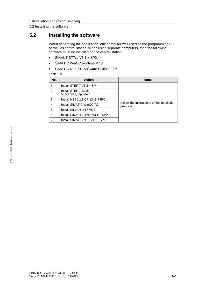
5.2 Installing the software
When generating the application, one computer was used as the programming PC as well as central station. When using separate computers, then the following software must be installed on the central station:
SINAUT ST7cc V3.1 + SP2
SIMATIC WinCC Runtime V7.3
SIMATIC NET PC Software Edition 2006
Table 5-3
No. Action Notes
1. Install STEP 7 V5.5 + SP4
Follow the instructions of the installation program.
2. Install STEP 7 Basic V13 + SP1, Update 4
3. Install HSP0111 CP 1243-8 IRC
4. Install SIMATIC WinCC 7.3
5. Install SINAUT ST7 V5.5
6. Install SINAUT ST7cc V3.1 + SP2
7. Install SIMATIC NET V13 + SP1

5 Installation and Commissioning
5.3 Installation of the application software
SINAUT ST7 with CP 1243-8 IRC/ MSC Entry ID: 109479747, V1.0, 11/2015 63
S
iem
en
s A
G 2
01
5 A
ll ri
gh
ts r
ese
rve
d
5.3 Installation of the application software
Unzip the file “109479747_CP1243-8_MSC_CODE_V10.zip”. This folder contains:
the archived STEP 7 V5.5 project “109479747_CP1243-8_MSC_V55_V10.zip”
the archived STEP 7 V13 project “109479747_CP1243-8_MSC_V13_V10.zip”
the archived ST7cc project “109479747_CP1243-8_ST7cc.zip”
the archived WinCC project “109479747_CP1243-8_WinCC_Project.zip”.
Retrieve the STEP 7 V5.5 project.
Unzip the STEP 7 V13 project, the St7cc project and the WinCC project.
5.4 Commissioning
5.4.1 Adjusting the GPRS provider
This application example was created with a Vodafone SIM card. If you use a SIM card of another provider, the provider properties need to be adjusted:
Table 5-4
No. Action
1. Start the SINAUT ST7 configuration tool.
“Start > Siemens automation > SIMATIC > SINAUT ST7 > Configuration”
2. Open the ST7 project.
3. Select “Subscriber Administration” and start with OK.
4. Open the list of GPRS providers via the globe icon.
5. Select the provider with your right mouse key and select the context menu “Edit provider data”.

5 Installation and Commissioning
5.4 Commissioning
SINAUT ST7 with CP 1243-8 IRC/ MSC Entry ID: 109479747, V1.0, 11/2015 64
S
iem
en
s A
G 2
01
5 A
ll ri
gh
ts r
ese
rve
d
No. Action
6. Enter the properties of your provider.
The information for Access Point Name, Username and Password will be provided by your GPRS provider.
Close the window with OK.

5 Installation and Commissioning
5.4 Commissioning
SINAUT ST7 with CP 1243-8 IRC/ MSC Entry ID: 109479747, V1.0, 11/2015 65
S
iem
en
s A
G 2
01
5 A
ll ri
gh
ts r
ese
rve
d
5.4.2 Entering the PIN of the SIM card
To be able to operate the example project, you have to enter the PIN of the SIM card for the GPRS station.
Table 5-5
1. Open the Properties dialog of master TIM by double clicking on Master TIM.
2. Go to the MSC Station List tab and double click on the GPRS station.
3. The window with the MSC station properties opens.
Enter the PIN of your SIM card.
Close the window with OK.

5 Installation and Commissioning
5.4 Commissioning
SINAUT ST7 with CP 1243-8 IRC/ MSC Entry ID: 109479747, V1.0, 11/2015 66
S
iem
en
s A
G 2
01
5 A
ll ri
gh
ts r
ese
rve
d
5.4.3 Entering the IP address of the DSL router in the central station
To be able to operate the example project, you have to adjust the IP address of the DSL router in the central station.
Table 5-6
No. Action
1. In the properties of master TIM you click on
the “MSC Master Properties” button.
2. Adjust the IP address of your provider.
Close the window with OK.
3. Save and compile your project.
4. Export the configuration data (see chapter 4.3.4).
5. Import the configuration data (see chapter 4.4.1).
Note If you do not have a fixed IP address, you use the fields “Name of the internet router” and “IP address of DNS Server” in step 2.

5 Installation and Commissioning
5.4 Commissioning
SINAUT ST7 with CP 1243-8 IRC/ MSC Entry ID: 109479747, V1.0, 11/2015 67
S
iem
en
s A
G 2
01
5 A
ll ri
gh
ts r
ese
rve
d
5.4.4 Configuring the DSL router
No specific router is discussed for the configuration as the operating screens differ from router to router.
Note For the configuration of the router you must assign an IP address to your PG/PC which is located in the internal network of the router.
Table 5-7
No. Action
1. Open the configuration user interface of the router.
This can be additional software, “Telnet”, or a web page.
2. Enter the connection data for your internet connection.
Login, password, etc. you received from your provider.
3. Enter your DNS server. You will receive the address together with your access data.
4. Specify a LAN IP address for the router.
In this example:
Router 1: 172.16.0.1
Router 2: 192.168.2.1
5. Forward the port that you defined in the SINAUT configuration as MSC port of the MSC Master to the same port of the TIM4R-IE (TIM 3V-IE).
Router 1: TCP port 26382 at port 26382 of
172.16.62.10

5 Installation and Commissioning
5.4 Commissioning
SINAUT ST7 with CP 1243-8 IRC/ MSC Entry ID: 109479747, V1.0, 11/2015 68
S
iem
en
s A
G 2
01
5 A
ll ri
gh
ts r
ese
rve
d
5.4.5 First commissioning of the engineering station
Assigning the IP address of the PC/PG
The table below shows the network setting to which you have to change the PC/PG.
Table 5-8
No. Action
1. Open the Internet Protocol (TCP/IP) Properties by selecting
“Start > Settings > Network Connections > Local Connections”.
2. In the open window, select “Internet Protocol (TCP/IP)” and open “Properties”.
3. Select the option box “Use following IP address”, and fill in the box as shown in the screen shot. Close the dialog boxes with “OK”.
Note:
This IP address must match the IP address configured in Netpro.
4. If your PG has an IWLAN interface, switch it off.

5 Installation and Commissioning
5.4 Commissioning
SINAUT ST7 with CP 1243-8 IRC/ MSC Entry ID: 109479747, V1.0, 11/2015 69
S
iem
en
s A
G 2
01
5 A
ll ri
gh
ts r
ese
rve
d
Importing a PC station
A “PC station“ is a PC with communication modules and software components within an automation solution with SIMATIC.
The hardware configuration of a PC station in SIMATIC is comparable with that of an S7 station. Components of a PC station such as modules or software interfaces are assigned to a virtual slot and parameterized in the same way.
Table 5-9
No. Action
1. Open the Component Configurator.
“Start > all Programs > Siemens Automation > Station Configurator”
2. Import the XDB file via the “Import Station” button
D:\ Projects\ST7_S7_1200\ XDBs\ pcst_1.xdb. (The file is available in your V5.5 project folder)
3. Execute the import with “OK”. The components are restarted.
Note
Should the components not be started immediately without error, please reboot the PC.
Note The import is only possible if the imported configuration corresponds with the locally existing configuration.

5 Installation and Commissioning
5.4 Commissioning
SINAUT ST7 with CP 1243-8 IRC/ MSC Entry ID: 109479747, V1.0, 11/2015 70
S
iem
en
s A
G 2
01
5 A
ll ri
gh
ts r
ese
rve
d
Specifying access points
After the configuration of the PC station, the access point of the ST7cc PC in the network is defined.
Table 5-10
No. Action
1. Open the SIMATIC NET “Communication Settings”.
2. Click on “Access Points” in the directory tree on the left.
The available access points are displayed in the right-hand window pane.
3. Open the access point “CP_H1_1” and select the setting of the used interface (Adapter.TCPIP) from the drop-down list “Associated interface parameter assignment”.
Clicking on “Apply” and “OK” closes the dialog.

5 Installation and Commissioning
5.4 Commissioning
SINAUT ST7 with CP 1243-8 IRC/ MSC Entry ID: 109479747, V1.0, 11/2015 71
S
iem
en
s A
G 2
01
5 A
ll ri
gh
ts r
ese
rve
d
5.4.6 Setting the transmission speed of the MD720
In this project, the transmission speed to the CPs is set to 9600 bits/s. CP and MD720 must support the same transmission speed.
The speed at the MD720 is modified using a terminal program.
Table 5-11
No. Action
1. Connect a PC to the serial interface of the MD720.
2. Start a terminal program, for example HyperTerminal.
3. Select the appropriate COM interface.
4. Set the character format and baud rate to the same values as the serial interface of the MD720.
The factory settings of the MD720 are as follows:
Baud rate: 19200 bits/s
Character format: 8N1.
The baud rate is changed via AT command “AT+IPR=<baud rate>”. Enter this command in the terminal program and press the return key.
Note The modem is only accessed by AT commands when it is in the command phase. If this is not the case, the modem must be reset to factory settings \9\.

5 Installation and Commissioning
5.4 Commissioning
SINAUT ST7 with CP 1243-8 IRC/ MSC Entry ID: 109479747, V1.0, 11/2015 72
S
iem
en
s A
G 2
01
5 A
ll ri
gh
ts r
ese
rve
d
5.4.7 Loading the TIM 4R-IE into the central station
Table 5-12
No. Action
1. Open the STEP 7 V5.5 project “ST7_S7_1200”
2. In the “PLC” menu, select the “Edit Ethernet Node” option.
3. Click on the “Browse…” button.
4. Select the TIM 4R-IE module and acknowledge the selection with the “OK” button.
In the “Set IP configurations” window which appears you enter the following details:
IP address: 192.168.1.10
Subnet mask: 255.255.255.0
Click on the “Assign IP Configuration” button.
Close the dialog.
5. Mark the “Master TIM” station in the SIMATIC Manager.
In the “PLC” menu you select the “Download” option.

5 Installation and Commissioning
5.4 Commissioning
SINAUT ST7 with CP 1243-8 IRC/ MSC Entry ID: 109479747, V1.0, 11/2015 73
S
iem
en
s A
G 2
01
5 A
ll ri
gh
ts r
ese
rve
d
5.4.8 Download of station 1 (S7-300 and TIM 3V-IE)
Table 5-13
No. Action
1. Open the internet protocol (TCP/IP) properties
Activate the checkbox “Use following IP-address” and enter the following address:
IP address: 192.168.0.100
Subnet mask: 255.255.255.0
Close the dialog boxes with “OK”.
2. In the “PLC” menu, select the “Edit Ethernet Node” option.
3. Click on the “Browse…” button.
4. Select the S7-300 CPU and confirm your selection by pressing the “OK” button.
In the “Set IP configurations” window which appears you enter the following details:
IP address: 192.168.0.2
Subnet mask: 255.255.255.0
Click on the “Assign IP Configuration” button.
Close the dialog.
5. In the SIMATIC Manager you select the station “01_Station”.
In the “PLC” menu you select the “Download” option.

5 Installation and Commissioning
5.4 Commissioning
SINAUT ST7 with CP 1243-8 IRC/ MSC Entry ID: 109479747, V1.0, 11/2015 74
S
iem
en
s A
G 2
01
5 A
ll ri
gh
ts r
ese
rve
d
5.4.9 Download of station 2 (S7-1200 and CP 1243-8 IRC)
Table 5-14
No. Action
1. Open the STEP 7 V13 project “ST7_S7_1200”.
2. Enable the security functions of the CP
ST7_S7_1200 > Global security settings > user login
User name: administrator
Password: administrator
3. Select station “PLC_1 [CPU1217C DC/DC/DC]”.
4. Download the project into the station.
5.4.10 Display of the communication states of CP 1243-8 IRC
The LEDs show the communication status of the module according to the following scheme.
Table 5-15
DIAG CONNECT
RS232
Meaning
Configuration of the telecontrol communication via the serial interface without errors and activated.
No connection established.
Configuration of the telecontrol communication via the serial interface without errors and activated.
All connections established or partner accessible.

5 Installation and Commissioning
5.4 Commissioning
SINAUT ST7 with CP 1243-8 IRC/ MSC Entry ID: 109479747, V1.0, 11/2015 75
S
iem
en
s A
G 2
01
5 A
ll ri
gh
ts r
ese
rve
d
5.4.11 Activating the ST7cc and starting ST7cc and WinCC Runtime
Adjusting the computer settings in the WinCC project
Note The setting of the computer name in WinCC and in Windows must be identical. For this reason, the server name in the System Properties of the WinCC project must be adjusted.
There is also the option to adjust the server name in Windows.
Table 5-16
No. Action
1. Start the WinCC Explorer and open the project “WinCC_Project.MCP”.
You find this project in folder “WinCC_Project”.
2. Open the System Properties.
3. In the “General” tab, you adapt the computer name.
4. In the “Startup” tab you activate “Tag Logging Runtime”, “Alarm Logging “Runtime”, and “Graphics Runtime”.
5. Save your configuration settings.
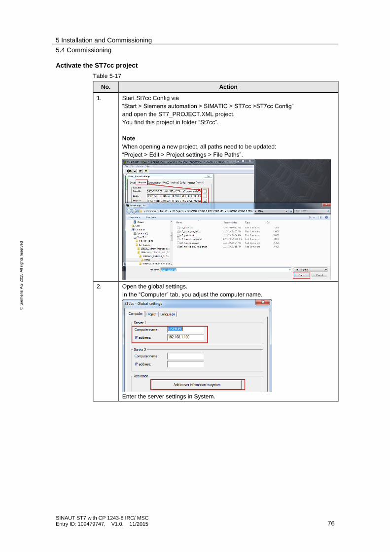
5 Installation and Commissioning
5.4 Commissioning
SINAUT ST7 with CP 1243-8 IRC/ MSC Entry ID: 109479747, V1.0, 11/2015 76
S
iem
en
s A
G 2
01
5 A
ll ri
gh
ts r
ese
rve
d
Activate the ST7cc project
Table 5-17
No. Action
1. Start St7cc Config via
“Start > Siemens automation > SIMATIC > ST7cc >ST7cc Config”
and open the ST7_PROJECT.XML project.
You find this project in folder “St7cc”.
Note
When opening a new project, all paths need to be updated:
“Project > Edit > Project settings > File Paths”.
2. Open the global settings.
In the “Computer” tab, you adjust the computer name.
Enter the server settings in System.

5 Installation and Commissioning
5.4 Commissioning
SINAUT ST7 with CP 1243-8 IRC/ MSC Entry ID: 109479747, V1.0, 11/2015 77
S
iem
en
s A
G 2
01
5 A
ll ri
gh
ts r
ese
rve
d
No. Action
3. In the “Project” you activate the current project for ST7cc Runtime.
Close the dialog with “OK”.
4. Save the settings.

5 Installation and Commissioning
5.4 Commissioning
SINAUT ST7 with CP 1243-8 IRC/ MSC Entry ID: 109479747, V1.0, 11/2015 78
S
iem
en
s A
G 2
01
5 A
ll ri
gh
ts r
ese
rve
d
Start ST7cc and WinCC Runtime
Table 5-18
No. Action
1. Start ST7cc Runtime via
“Start > Siemens automation > SIMATIC > ST7cc > ST7cc-Runtime”.
2. The DOS output window opens and displays information on which programs are successively started by ST7cc.
Note:
The window must not be closed manually.
3. The Log window of the SINAUT server opens. Amongst other things, it also shows the connections with the SINAUT subscribers and the fact that the general queries for these subscribers, automatically started at system start, were terminated without error.
ST7cc server running.

5 Installation and Commissioning
5.4 Commissioning
SINAUT ST7 with CP 1243-8 IRC/ MSC Entry ID: 109479747, V1.0, 11/2015 79
S
iem
en
s A
G 2
01
5 A
ll ri
gh
ts r
ese
rve
d
No. Action
4. In the WinCC Explorer you start WinCC Runtime.
5. Your ST7 demo plant is now ready for operation.
Note If the time in a station is not valid (Clock indicator: “red”), you need to start a general request again.
In the “Overview” screen you click on the corresponding buttons. The Details view opens. Start a new general request.

6 Operating the Application
6.1 Overview and description of the user interface
SINAUT ST7 with CP 1243-8 IRC/ MSC Entry ID: 109479747, V1.0, 11/2015 80
S
iem
en
s A
G 2
01
5 A
ll ri
gh
ts r
ese
rve
d
6 Operating the Application In the following chapters, we will introduce the operation of the demo-project as well as the test and diagnostic functions provided by the used components:
6.1 Overview and description of the user interface
Figure 6-1
Overview
Communication
Alarm
Archive

6 Operating the Application
6.1 Overview and description of the user interface
SINAUT ST7 with CP 1243-8 IRC/ MSC Entry ID: 109479747, V1.0, 11/2015 81
S
iem
en
s A
G 2
01
5 A
ll ri
gh
ts r
ese
rve
d
6.1.1 “Overview” screen
The “Overview” screen shows all relevant messages, the hardware setup of the application example, and the status of all subscribers.
Subscriber Status
Table 6-1
Screen Description
On this screen, the status of:
the control center
the local TIM
both substations
can be viewed.
You can open a details list by moving the left mouse-button over the respective image.
These faceplates are generated by
SINAUT depending on the configuration and
can be easily included into a project.
Details view
Control center:
Apart from the existing ST7cc server and the directly connected TIMs, the status of the TCO (communication module of the ST7cc software) is also displayed.

6 Operating the Application
6.1 Overview and description of the user interface
SINAUT ST7 with CP 1243-8 IRC/ MSC Entry ID: 109479747, V1.0, 11/2015 82
S
iem
en
s A
G 2
01
5 A
ll ri
gh
ts r
ese
rve
d
Screen Description
Details view
Local TIM:
The picture typical indicates, whether:
the TIM is accessible (subscriber)
the last general request to the TIM was completed without error (GR), and
the time on the TIM is ok (Clock).
In the details view, you can trigger a general request to the TIM manually (General request), which will then transfer your latest accountancy information. The processing of the general request can be followed on the GR display as well as in text field GR in the faceplate.
Station 1 (S7-300):
The picture typical indicates, whether:
the station CPU is accessible (subscriber)
the last general request to the station was completed without error (GR), and
the time in the station is ok (Clock).

6 Operating the Application
6.1 Overview and description of the user interface
SINAUT ST7 with CP 1243-8 IRC/ MSC Entry ID: 109479747, V1.0, 11/2015 83
S
iem
en
s A
G 2
01
5 A
ll ri
gh
ts r
ese
rve
d
Screen Description
Details view
In the details view, a general request can also be triggered (General request). From the TIM in the station, all data frames possibly still stored there can be transmitted as well as a current process image.
Both further command options (Permanent connection on / off) are only relevant for a station connected via dialup network or dedicated line.
Details view
Station 2 (S7-1200):
The picture typical indicates, whether:
the station CPU is accessible (subscriber)
the last general request to the station was completed without error (GR), and
the time in the station is ok (Clock).
In the details view, a general request can also be triggered (General request). From the TIM in the station, all data frames possibly still stored there can be transmitted as well as a current process image.
Both further command options (Permanent connection on / off) are only relevant for a station connected via dialup network or dedicated line.
Display of the relevant messages (see description of the “Alarm” screen)

6 Operating the Application
6.1 Overview and description of the user interface
SINAUT ST7 with CP 1243-8 IRC/ MSC Entry ID: 109479747, V1.0, 11/2015 84
S
iem
en
s A
G 2
01
5 A
ll ri
gh
ts r
ese
rve
d
6.1.2 “Communication” screen
The “Communication” screen shows the connection status of both substations. With this screen, two stations can be controlled and monitored.
Table 6-2
Screen Description
Details view
Station 1 (S7-300):
The picture typical indicates, whether:
the station CPU is accessible (subscriber)
the last general request to the station was completed without error (GR), and
the time in the station is ok (Clock).
In the details view, a general request can also be triggered (General request). From the TIM in the station, all data frames possibly still stored there can be transmitted as well as a current process image.
Both further command options (Permanent connection on / off) are only relevant for a station connected via dialup network or dedicated line.

6 Operating the Application
6.1 Overview and description of the user interface
SINAUT ST7 with CP 1243-8 IRC/ MSC Entry ID: 109479747, V1.0, 11/2015 85
S
iem
en
s A
G 2
01
5 A
ll ri
gh
ts r
ese
rve
d
Screen Description
Details view
Station 2 (S7-1200):
The picture typical indicates, whether:
the station CPU is accessible (subscriber)
the last general request to the station was completed without error (GR), and
the time in the station is ok (Clock).
In the details view, a general request can also be triggered (General request). From the TIM in the station, all data frames possibly still stored there can be transmitted as well as a current process image.
Both further command options (Permanent connection on / off) are only relevant for a station connected via dialup network or dedicated line.
Station 1 (S7-300):
“Operating Mode”: Operating mode of the station
– automatic mode
– manual mode
“Operating Status”
– On: switched on
– Off: switched off

6 Operating the Application
6.1 Overview and description of the user interface
SINAUT ST7 with CP 1243-8 IRC/ MSC Entry ID: 109479747, V1.0, 11/2015 86
S
iem
en
s A
G 2
01
5 A
ll ri
gh
ts r
ese
rve
d
Screen Description
Station 2 (S7-1200):
“Operating Mode”: Operating mode of the station
– automatic mode
– manual mode
“Operating Status”
– On: switched on
– Off: switched off
Note:
In automatic mode, the operating status cannot be modified manually.
6.1.3 “Archive” screen
The process tags are stored in an archive. The “Archives” screen displays stored tags of the individual substations.
Table 6-3
Screen Description
Station 1 (S7-300):
Table with the stored values “OperatingMode” and “OperatingStatus”
“Operating Mode”:
“0”: automatic mode
“1”: manual mode
“OperatingStatus”
“0”: Off
“1”: On
Station 2 (S7-1200):
Table with the stored values “OperatingMode” and “OperatingStatus”
“Operating Mode”:
“0”: automatic mode
“1”: manual mode
“OperatingStatus”
“0”: Off
“1”: On

6 Operating the Application
6.2 Watch tables “WT_SetPump”
SINAUT ST7 with CP 1243-8 IRC/ MSC Entry ID: 109479747, V1.0, 11/2015 87
S
iem
en
s A
G 2
01
5 A
ll ri
gh
ts r
ese
rve
d
Screen Description
Station 1 (S7-300):
Display of the trends of the stored values “OperatingMode” and “OperatingStatus”
: Operating Mode
: Operating Status
Station 2 (S7-1200):
Display of the trends of the stored values “OperatingMode” and “OperatingStatus”
: Operating Mode
: Operating Status
Joint display of the trends of station 1 (S7-300) and station 2 (S7-1200)
: Operating Mode Station 2
: Operating Status Station 2
: Operating Mode Station 1
: Operating Status Station 1
6.2 Watch tables “WT_SetPump”
As an alternative to the WinCC user interface, the "WT_SetPump" watch table of the stations can be used for monitoring or controlling the tags of DB “DATA” (DB).
Figure 6-2 Station 1_Tag_table “WT_SetPump”

6 Operating the Application
6.2 Watch tables “WT_SetPump”
SINAUT ST7 with CP 1243-8 IRC/ MSC Entry ID: 109479747, V1.0, 11/2015 88
S
iem
en
s A
G 2
01
5 A
ll ri
gh
ts r
ese
rve
d
Figure 6-3 Station 2_Watch_table “WT_SetPump”
Note A description of the tags is available in Table 3-4.

6 Operating the Application
6.3 Cyclic switching of the operating state of the pumps in automatic mode
SINAUT ST7 with CP 1243-8 IRC/ MSC Entry ID: 109479747, V1.0, 11/2015 89
S
iem
en
s A
G 2
01
5 A
ll ri
gh
ts r
ese
rve
d
6.3 Cyclic switching of the operating state of the pumps in automatic mode
Requirements:
The ST7cc project was activated (see chapter 5.4.11)
St7cc and WinCC Runtime were started (see chapter 5.4.11)
The “Overview” screen was opened.
Table 6-4
No. Action
1. Go to the “Communication” screen.
2. Switch both stations to “Automatic mode”.

6 Operating the Application
6.3 Cyclic switching of the operating state of the pumps in automatic mode
SINAUT ST7 with CP 1243-8 IRC/ MSC Entry ID: 109479747, V1.0, 11/2015 90
S
iem
en
s A
G 2
01
5 A
ll ri
gh
ts r
ese
rve
d
No. Action
3. After 30 seconds, the “Operating Status” of both stations is switched over automatically.
Note:
In automatic mode, the pumps cannot be operated manually.
4. You can view all of the archived values in “Archive” screen.
: Operating Mode Station 2
: Operating Status Station 2
: Operating Mode Station 1
: Operating Status Station 1
5. Terminate the Ethernet connection between station 2 (S7-1200) and the central station and repeat steps 1-4 of this table.

6 Operating the Application
6.4 Automatic switching of a pump (automatic mode), when changing the operating state of the second pump (manual mode).
SINAUT ST7 with CP 1243-8 IRC/ MSC Entry ID: 109479747, V1.0, 11/2015 91
S
iem
en
s A
G 2
01
5 A
ll ri
gh
ts r
ese
rve
d
6.4 Automatic switching of a pump (automatic mode), when changing the operating state of the second pump (manual mode).
Requirements:
• The ST7cc project was activated (see chapter 5.4.11)
• St7cc and WinCC Runtime were started (see chapter 5.4.11)
• The “Overview” screen was opened.
Table 6-5
No. Action
1. Go to the “Communication” screen.
2. Switch station 1 to “Manual mode” and station 2 to “Automatic mode”.

6 Operating the Application
6.4 Automatic switching of a pump (automatic mode), when changing the operating state of the second pump (manual mode).
SINAUT ST7 with CP 1243-8 IRC/ MSC Entry ID: 109479747, V1.0, 11/2015 92
S
iem
en
s A
G 2
01
5 A
ll ri
gh
ts r
ese
rve
d
No. Action
3. Switch off the pump of station 1.
4. The pump in station 2 is automatically switched on.
5. You can view all of the archived values in “Archive” screen.
: Operating Mode Station 2
: Operating Status Station 2
: Operating Mode Station 1
: Operating Status Station 1
6. Terminate the Ethernet connection between station 2 (S7-1200) and the central station and repeat steps 1-5 of this table.
Note The rules for station 2 (S7-1200) in automatic mode and station 1 (S7-300) in manual mode apply accordingly vice versa for station 1 (S7-300) in automatic mode and station 2 (S7 1200) in manual mode.

7 Links & Literature
SINAUT ST7 with CP 1243-8 IRC/ MSC Entry ID: 109479747, V1.0, 11/2015 93
S
iem
en
s A
G 2
01
5 A
ll ri
gh
ts r
ese
rve
d
7 Links & Literature Table 7-1
Topic Title
\1\ Siemens Industry Online Support
http://support.industry.siemens.com
\2\ Download page of the entry
https://support.industry.siemens.com/cs/ww/en/109479747
\3\ SIMATIC NET Industrial Remote Communication - TeleControl SINAUT ST7 Station Control System
https://support.industry.siemens.com/cs/ww/en/view/55639671
\4\ SIMATIC NET SINAUT ST7 Station Control System - System Manual
https://support.industry.siemens.com/cs/ww/en/view/63112365
\5\ WinCC V7.3: Communication
https://support.industry.siemens.com/cs/ww/en/view/102691766
\6\ SIMATIC NET S7-1200 - TeleControl CP 1243-8 IRC - Operating Instructions
https://support.industry.siemens.com/cs/ww/en/view/109478160
\7\ SIMATIC NET Telecontrol SINAUT ST7cc Control Center Software Manual
https://support.industry.siemens.com/cs/ww/en/view/63203610
\8\ WinCC V7.3: Working with WinCC
https://support.industry.siemens.com/cs/ww/en/view/102754925
\9\ SIMATIC NET
Industrial Remote Communication - TeleControl
MODEM MD720
https://support.industry.siemens.com/cs/ww/en/view/102401328
8 History
Table 8-1
Version Date Modifications
V1.0 10/2015 First version