application example 08/2016 ethernet … example 08/2016 ethernet communication between simatic s5...
TRANSCRIPT

https://support.industry.siemens.com/cs/ww/en/view/109482475
Application Example 08/2016
Ethernet Communication between SIMATIC S5 and SIMATIC S7-1500 Controllers CP1543-1, CP1430 TCP

Warranty and Liability
Kommunikation S5 zu S7-1500 Entry ID: 109482475, V1.0, 08/2016 2
S
iem
en
s A
G 2
91
6 A
ll ri
gh
ts r
ese
rve
d
Warranty and Liability
Note The Application Examples are not binding and do not claim to be complete with regard to configuration, equipment or any contingencies. The Application Examples do not represent customer-specific solutions. They are only intended to provide support for typical applications. You are responsible for the correct operation of the described products. These Application Examples do not relieve you of the responsibility of safely and professionally using, installing, operating and servicing equipment. When using these Application Examples, you recognize that we cannot be made liable for any damage/claims beyond the liability clause described. We reserve the right to make changes to these Application Examples at any time and without prior notice. If there are any deviations between the recommendations provided in this Application Example and other Siemens publications – e. g. catalogs – the contents of the other documents shall have priority.
We do not accept any liability for the information contained in this document. Any claims against us – based on whatever legal reason – resulting from the use of the examples, information, programs, engineering and performance data etc., described in this Application Example shall be excluded. Such an exclusion shall not apply in the case of mandatory liability, e.g. under the German Product Liability Act (“Produkthaftungsgesetz”), in case of intent, gross negligence, or injury of life, body or health, guarantee for the quality of a product, fraudulent concealment of a deficiency or breach of fundamental contractual obligations (“wesentliche Vertragspflichten”). The compensation for damages due to a breach of a fundamental contractual obligation is, however, limited to the foreseeable damage, typical for the type of contract, except in the event of intent or gross negligence or injury to life, body or health. The above provisions do not imply a change of the burden of proof to your detriment. Any form of duplication or distribution of these Application Examples or excerpts hereof is prohibited without the expressed consent of Siemens AG.
Security informa-
tion
Siemens provides products and solutions with Industrial Security functions that support the secure operation of plants, systems, machines and networks.
In order to secure plants, systems, machines and networks against cyber threats it is necessary to implement (and to maintain continuously) a holistic, state-of-the-art Industrial Security concept. With this in mind, Siemens’ products and solutions are only part of such a concept.
It is the client’s responsibility to prevent unauthorized access to his plants, systems, machines and networks. Systems, machines and components should only be connected with the company’s network or the Internet, when and insofar as this is required and the appropriate protective measures (for example, use of firewalls and network segmentation) have been taken.
In addition, Siemens’ recommendations regarding appropriate protective action should be followed. For more information on Industrial Security, visit http://www.Siemens.com/industrialsecurity.
Siemens’ products and solutions undergo continuous development to make them even more secure. Siemens explicitly recommends to carry out updates as soon as the respective updates are available and always only to use the current product versions. Use of product versions that are no longer supported, and failure to apply latest updates may increase customer’s exposure to cyber threats.
In order to always be informed about product updates, subscribe to the Siemens Industrial Security RSS Feed at http://www.Siemens.com/industrialsecurity.

Table of Contents
Kommunikation S5 zu S7-1500 Entry ID: 109482475, V1.0, 08/2016 3
S
iem
en
s A
G 2
91
6 A
ll ri
gh
ts r
ese
rve
d
Table of Contents Warranty and Liability ................................................................................................. 2
1 Task ..................................................................................................................... 5
1.1 Overview............................................................................................... 5
2 Solution............................................................................................................... 7
2.1 Overview............................................................................................... 7 2.2 Hardware and software components ................................................. 10
3 Configuration and Settings............................................................................. 12
3.1 Scenario 1 – Communication via FETCH/WRITE and CP1543-1 ..... 12 3.1.1 Mode of operation .............................................................................. 12 3.1.2 Communication program in the SIMATIC S7-1500 ............................ 14 3.1.3 Communication program SIMATIC S5 ............................................... 17 3.1.4 Connection configuration in the SIMATIC S7-1500 ........................... 19 3.1.5 Connection configuration in the CP1430 TCP (SIMATIC S5) ............ 23 3.2 Scenario 2a – Communication via parameterized OUC (single
instructions) and internal CPU interface ............................................. 29 3.2.1 Mode of operation .............................................................................. 29 3.2.2 Communication program in the SIMATIC S7-1500 ............................ 31 3.2.3 Communication program SIMATIC S5 ............................................... 33 3.2.4 Connection configuration in the S7-1500 CPU .................................. 35 3.2.5 Connection configuration in the CP1430 TCP (SIMATIC S5) ............ 37 3.3 Scenario 2b – Communication via programmed OUC (single
instructions) and internal CPU interface ............................................. 40 3.3.1 Mode of operation .............................................................................. 40 3.3.2 Communication program in the SIMATIC S7-1500 ............................ 42 3.3.3 Communication program SIMATIC S5 ............................................... 44 3.3.4 Connection configuration in the S7-1500 CPU .................................. 45 3.3.5 Connection configuration in the CP1430 TCP (SIMATIC S5) ............ 47 3.4 Scenario 3 – Communication via programmed OUC (compact
instruction) and CP1543-1 interface ................................................... 49 3.4.1 Mode of operation .............................................................................. 49 3.4.2 Communication program in the SIMATIC S7-1500 ............................ 50 3.4.3 Communication program SIMATIC S5 ............................................... 52 3.4.4 Connection configuration in the S7-1500 CPU .................................. 54 3.4.5 Connection configuration in the CP1430 TCP (SIMATIC S5) ............ 55 3.5 Scenario 4a – Communication via parameterized OUC (single
instructions) and CP1543-1 ................................................................ 57 3.5.1 Mode of operation .............................................................................. 57 3.5.2 Communication program in the SIMATIC S7-1500 ............................ 59 3.5.3 Communication program SIMATIC S5 ............................................... 61 3.5.4 Connection configuration in the S7-1500 CPU .................................. 63 3.5.5 Connection configuration in the CP1430 TCP (SIMATIC S5) ............ 65 3.6 Scenario 4b – Communication via programmed OUC (single
instructions) and CP1543-1 ................................................................ 67 3.6.1 Mode of operation .............................................................................. 67 3.6.2 Communication program in the SIMATIC S7-1500 ............................ 68 3.6.3 Communication program SIMATIC S5 ............................................... 71 3.6.4 Connection configuration in the S7-1500 CPU .................................. 73 3.6.5 Connection configuration in the CP1430 TCP (SIMATIC S5) ............ 74 3.7 Scenario 5 – Communication via programmed OUC (compact
instructions) and internal CPU interface ............................................. 76 3.7.1 Mode of operation .............................................................................. 76 3.7.2 Communication program in the SIMATIC S7-1500 ............................ 78 3.7.3 Communication program SIMATIC S5 ............................................... 80
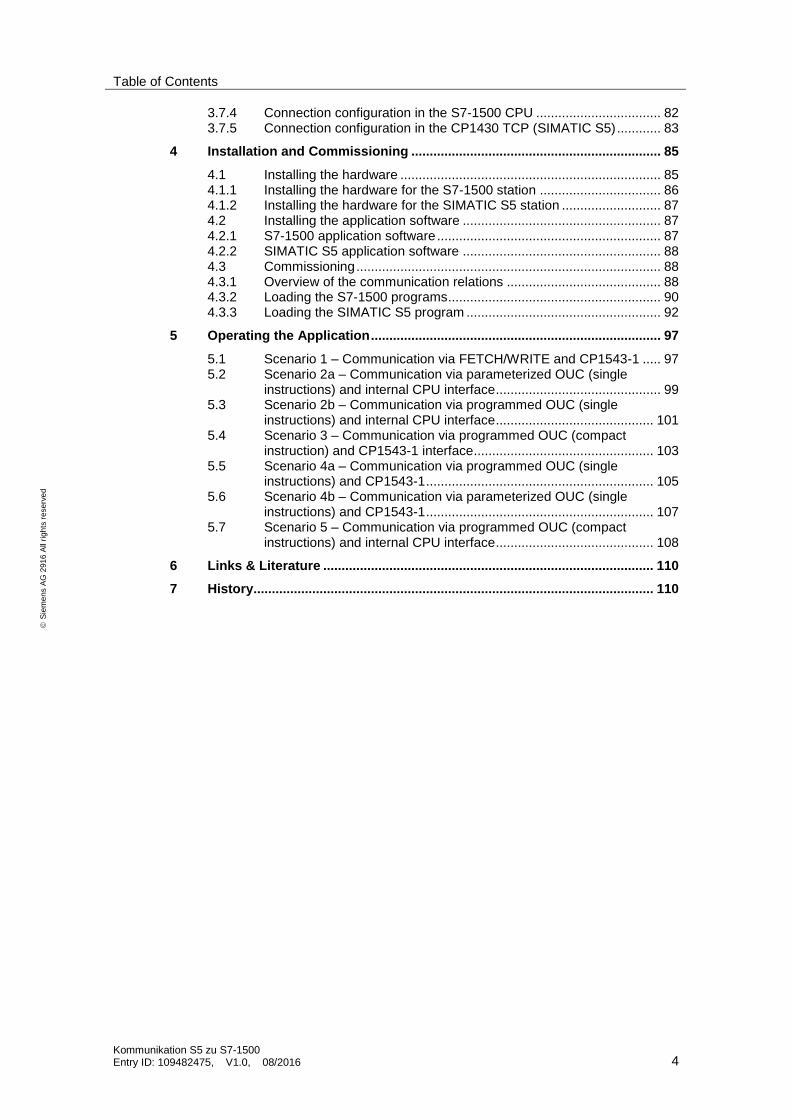
Table of Contents
Kommunikation S5 zu S7-1500 Entry ID: 109482475, V1.0, 08/2016 4
S
iem
en
s A
G 2
91
6 A
ll ri
gh
ts r
ese
rve
d
3.7.4 Connection configuration in the S7-1500 CPU .................................. 82 3.7.5 Connection configuration in the CP1430 TCP (SIMATIC S5) ............ 83
4 Installation and Commissioning .................................................................... 85
4.1 Installing the hardware ....................................................................... 85 4.1.1 Installing the hardware for the S7-1500 station ................................. 86 4.1.2 Installing the hardware for the SIMATIC S5 station ........................... 87 4.2 Installing the application software ...................................................... 87 4.2.1 S7-1500 application software ............................................................. 87 4.2.2 SIMATIC S5 application software ...................................................... 88 4.3 Commissioning ................................................................................... 88 4.3.1 Overview of the communication relations .......................................... 88 4.3.2 Loading the S7-1500 programs .......................................................... 90 4.3.3 Loading the SIMATIC S5 program ..................................................... 92
5 Operating the Application ............................................................................... 97
5.1 Scenario 1 – Communication via FETCH/WRITE and CP1543-1 ..... 97 5.2 Scenario 2a – Communication via parameterized OUC (single
instructions) and internal CPU interface ............................................. 99 5.3 Scenario 2b – Communication via programmed OUC (single
instructions) and internal CPU interface ........................................... 101 5.4 Scenario 3 – Communication via programmed OUC (compact
instruction) and CP1543-1 interface ................................................. 103 5.5 Scenario 4a – Communication via programmed OUC (single
instructions) and CP1543-1 .............................................................. 105 5.6 Scenario 4b – Communication via parameterized OUC (single
instructions) and CP1543-1 .............................................................. 107 5.7 Scenario 5 – Communication via programmed OUC (compact
instructions) and internal CPU interface ........................................... 108
6 Links & Literature .......................................................................................... 110
7 History............................................................................................................. 110

1 Task
1.1 Overview
Kommunikation S5 zu S7-1500 Entry ID: 109482475, V1.0, 08/2016 5
S
iem
en
s A
G 2
91
6 A
ll ri
gh
ts r
ese
rve
d
1 Task
1.1 Overview
Introduction
In automation technology, more and more old systems have to be upgraded step by step from SIMATIC S5 to SIMATIC S7.
Normally, partial migration is done by successively replacing the S5 stations of an old system by a SIMATIC S7 station. However, the communication relations to other SIMATIC S5 stations have to be maintained.
These examples shall demonstrate how to link a SIMATIC S5 station to a modern SIMATIC S7-1500 station via Industrial Ethernet.
Overview of the automation task
The figure below shows a frequently occurring communication structure of existing S5 systems.
Figure 1-1
PC control station / SIMATIC S5 head-end
SIMATIC S5 substations
Migration substation from
SIMATIC S5 -> S7-1500
……
FETCH/
WRITE
SEND/
RECV
Description of the automation task
One of the standard communication structures for systems is the star topology. A head-end station (PC or SIMATIC head-end station) communicates with several substations. These substations, however, also communicate with each other via cross-communication.

1 Task
1.1 Overview
Kommunikation S5 zu S7-1500 Entry ID: 109482475, V1.0, 08/2016 6
S
iem
en
s A
G 2
91
6 A
ll ri
gh
ts r
ese
rve
d
In SIMATIC S5 systems, the communication of a control center/S5 head-end station to its substations is often implemented by means of the FETCH/WRITE service (level 7 communication). Cross-communication between S5 substations is done via the SEND/RECEIVE service (level 4 communication).
In the course of a partial migration, a SIMATIC S5 station is replaced by a SIMATIC S7-1500 station.
The example projects/scenarios in this document show the options available to establish a communication via Industrial Ethernet between the existing SIMATIC S5 controllers and the SIMATIC S7-1500 via the available protocols and
services.

2 Solution
2.1 Overview
Kommunikation S5 zu S7-1500 Entry ID: 109482475, V1.0, 08/2016 7
S
iem
en
s A
G 2
91
6 A
ll ri
gh
ts r
ese
rve
d
2 Solution
2.1 Overview
Schematic layout
The figure below shows a schematic overview of the most important components and variants of this solution:
Figure 2-1
SIMATIC S5-115U station
CP
14
30
TC
P
SIMATIC S7-1500 station
CP
U
94
4
CP
15
43-1
CP
U
15
16-3
PN
Industrial Ethernet
TIAP STEP 7
STEP 5
RS232/TTY
PG
Engineering station
1
2a
3
4a
5
2b
4b
FETCH/WRITE
OUC programmed
OUC parameterized
OUC programmed (compact)
OUC parameterized
OUC programed
OUC programmed (compact)
OUC: Open User Communication
Setup
In this example, a SIMATIC S5-115U is used exemplarily on the S5 end. Basically, however, the solutions presented here also work with S5-135U and S5-155U controllers.
For these SIMATIC S5 controller families, the CP1430 TCP communication processor is available which implements the TCP/IP and ISO-on-TCP (RFC 1006) protocols as well as, based on this, the active/passive FETCH/WRITE service.
On the S7-1500 end, the coupling to the CP1430 TCP can be made via the integrated PROFINET interface of the S7-CPU or via the Industrial Ethernet interface of the CP1543-1. This results in various communication variants which will be explained in detail in the following chapters.
Engineering is done for the
SIMATIC S5 station with STEP 5 and the NCM COM 1430 TCP package
SIMATIC S7-1500 station with STEP 7 V13 SP1 (TIA Portal).

2 Solution
2.1 Overview
Kommunikation S5 zu S7-1500 Entry ID: 109482475, V1.0, 08/2016 8
S
iem
en
s A
G 2
91
6 A
ll ri
gh
ts r
ese
rve
d
Implemented communication functions
The table below shows all communication variants that have been implemented in the different ways illustrated in Figure 2-1. A detailed description of the different functions is available in chapter3 “Configuration and Settings”.
SIMATIC S5 - CP1430 TCP
S5 service Active FETCH/WRITE
SEND/ RECEIVE
bidirectional
S7-1500 service
Passive FETCH/WRITE
OUC programmed
via
compact instruction
2
OUC programmed
via
single instruction
1
OUC programmed
via
single instruction
1
via
CP1543-1 Scen. 1 Scen. 3 Scen. 4b Scen. 4a
via
S7-1500 CPU Scen. 5 Scen. 2b Scen. 2a
1 Single instructions (TCON, TDISCON, TSEND, TRCV...)
2 Compact instructions (TSEND_C, TRCV_C)
active partner for establishing a connection
passive partner for establishing a connection
Scenario Short description
1 FETCH/WRITE function
Via the CP1430 TCP, the SIMATIC S5 actively establishes a FETCH/WRITE
connection to the passively responding CP1543-1. The S5 reads the data block areas from the S7-1500 CPU which have been configured in the CP1430 TCP and, vice versa, can write data directly into the S7-1500 data blocks via a WRITE job. The S7-1500 CPU does not contain any communication blocks.
The SIMATIC S5 controller uses the handling blocks FETCH and SEND (RW).
2a Parameterized OUC communication via the integrated PROFINET SS and single instructions – TSEND/TRCV Using the integrated PROFINET interface, the SIMATIC S7 CPU actively
establishes an ISO-on-TCP connection to the SIMATIC S5 CPU via the CP1430 TCP.
On the S7-1500 CPU end, the connection is established via a parameterized configuration and the data are sent and received via the OUC blocks TSEND and TRCV. In this case, the connection data are configured in offline mode.
For this connection, the SIMATIC S5 uses the standard handling blocks SEND/RECEIVE. The connection in the SIMATIC S5 is configured in the CP1430 TCP.
2b Programmed OUC communication via the integrated PROFINET SS and single instructions – TSEND/TRCV Via the CP1430 TCP, the SIMATIC S5 actively establishes an ISO-on-TCP
connection to the S7-1500 CPU using the integrated PROFINET interface. On the S7-1500 CPU end, the connection is established via the OUC blocks TCON in the user program and the data are sent and received via TSEND and TRCV.
2a
A
P
A
A P
A A P
A

2 Solution
2.1 Overview
Kommunikation S5 zu S7-1500 Entry ID: 109482475, V1.0, 08/2016 9
S
iem
en
s A
G 2
91
6 A
ll ri
gh
ts r
ese
rve
d
Scenario Short description
For this connection, the SIMATIC S5 uses the standard handling blocks SEND/RECEIVE. The connection in the SIMATIC S5 is configured in the CP1430 TCP.
3 Programmed OUC communication via CP1543-1 and compact instructions – TSEND/TRCV_C Via the CP1543-1, the SIMATIC S7 CPU actively establishes an ISO-on-TCP
connection to the S5-CPU using the CP1430 TCP. In the S7-1500 CPU, the connection is established via the compact OUC block TSEND_C and the TRCV using the user program and the data are sent and received. For this connection, the SIMATIC S5 uses the standard handling blocks SEND/RECEIVE. The connection in the SIMATIC S5 is configured in the CP1430 TCP.
4a Parameterized OUC communication via CP1543-1 and single instructions – TSEND/TRCV
Via the CP1543-1, the SIMATIC S7 CPU actively establishes an ISO-on-TCP
connection to the S5-CPU using the CP1430 TCP. On the S7-1500 CPU end, the connection is established via the OUC blocks TCON and the data are sent and received via TSEND and TRCV. In this case, however, the connection data are configured in offline mode.
For this connection, the SIMATIC S5 uses the standard handling blocks SEND/RECEIVE. The connection in the SIMATIC S5 is configured in the CP1430 TCP.
4b Programmed OUC communication via CP1543-1 and single instructions – TSEND/TRCV
Via the CP1543-1, the SIMATIC S7 CPU actively establishes an ISO-on-TCP
connection to the S5-CPU using the CP1430 TCP. On the S7-1500 CPU end, the connection is established via the OUC blocks TCON in the user program and the data are sent and received via TSEND and TRCV. For this connection, the SIMATIC S5 uses the standard handling blocks SEND/RECEIVE. The connection in the SIMATIC S5 is configured in the CP1430 TCP.
5 Programmed OUC communication via the integrated PROFINET SS and compact instructions – TSEND_C/TRCV Via the CP1430 TCP, the SIMATIC S5 actively establishes an ISO-on-TCP
connection to the S7-1500 CPU using the integrated PROFINET interface. In the S7-1500 CPU, the connection is established via the compact OUC block TSEND_C and the TRCV using the user program and the data are sent and received. For this connection, the SIMATIC S5 uses the standard handling blocks SEND/RECEIVE. The connection in the SIMATIC S5 is configured in the CP1430 TCP.
Advantages
The examples presented here offer the following advantages:
You will get information on all possible variants of an Ethernet communication between a SIMATIC S5 and S7.
You will be provided with master copies which can be quickly used and extended in your own migration projects.
Detailed knowledge on the SIMATIC S5 is not required.
2 Solution
2.2 Hardware and software components
Kommunikation S5 zu S7-1500 Entry ID: 109482475, V1.0, 08/2016 10
S
iem
en
s A
G 2
91
6 A
ll ri
gh
ts r
ese
rve
d
Topics not covered by this application
This example includes
No detailed explanation of the SIMATIC S5 and SIMATIC S7-1500 and their communication options.
No introduction to the programming of SIMATIC S5 and SIMATIC S7 controllers.
Basic knowledge of these topics is assumed.
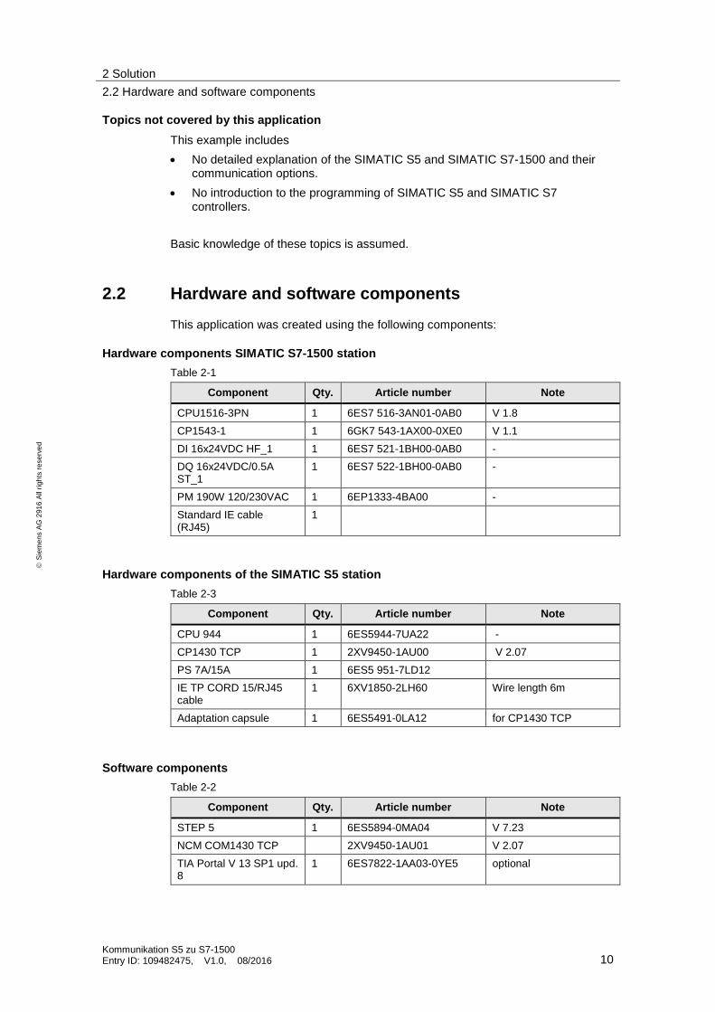
2.2 Hardware and software components
This application was created using the following components:
Hardware components SIMATIC S7-1500 station
Table 2-1
Component Qty. Article number Note
CPU1516-3PN 1 6ES7 516-3AN01-0AB0 V 1.8
CP1543-1 1 6GK7 543-1AX00-0XE0 V 1.1
DI 16x24VDC HF_1 1 6ES7 521-1BH00-0AB0 -
DQ 16x24VDC/0.5A ST_1
1 6ES7 522-1BH00-0AB0 -
PM 190W 120/230VAC 1 6EP1333-4BA00 -
Standard IE cable (RJ45)
1
Hardware components of the SIMATIC S5 station
Table 2-3
Component Qty. Article number Note
CPU 944 1 6ES5944-7UA22 -
CP1430 TCP 1 2XV9450-1AU00 V 2.07
PS 7A/15A 1 6ES5 951-7LD12
IE TP CORD 15/RJ45 cable
1 6XV1850-2LH60 Wire length 6m
Adaptation capsule 1 6ES5491-0LA12 for CP1430 TCP
Software components
Table 2-2
Component Qty. Article number Note
STEP 5 1 6ES5894-0MA04 V 7.23
NCM COM1430 TCP 2XV9450-1AU01 V 2.07
TIA Portal V 13 SP1 upd. 8
1 6ES7822-1AA03-0YE5 optional

2 Solution
2.2 Hardware and software components
Kommunikation S5 zu S7-1500 Entry ID: 109482475, V1.0, 08/2016 11
S
iem
en
s A
G 2
91
6 A
ll ri
gh
ts r
ese
rve
d
Example files and projects
The following list includes all files and projects that are used in this example.
Table 2-3
Component Note
109482475_Comm_S71500_PROJ_v10.zip This zip file contains the STEP 7 project for the S7-1500 station.
109482475_Comm_S5_PROJ_v10.zip This zip file contains all STEP 5 projects and the NCM project file for the CP1430 TCP.
109482475_Comm_S5-S71500_DOC_v10_de.pdf
This document

3 Configuration and Settings
3.1 Scenario 1 – Communication via FETCH/WRITE and CP1543-1
Kommunikation S5 zu S7-1500 Entry ID: 109482475, V1.0, 08/2016 12
S
iem
en
s A
G 2
91
6 A
ll ri
gh
ts r
ese
rve
d
3 Configuration and Settings
Overview
The following chapters will give you a detailed overview of all communication variants.
Table 3-1
SIMATIC S5 - CP1430 TCP
S5 service Active FETCH/WRITE
SEND/ RECEIVE
Bidirectional
S7-1500 service
Passive
FETCH/WRITE
OUC programmed
via
compact instruction
OUC programmed
via
single instructions
OUC parameterized
via
single instructions
via
CP1543-1 Scenario 1 Scenario 3 Scenario 4b Scenario 4a
via
S7-1500 CPU Scenario 5 Scenario 2b Scenario 2a
3.1 Scenario 1 – Communication via FETCH/WRITE and CP1543-1
3.1.1 Mode of operation
Overview
Via the CP1430 TCP, the SIMATIC S5 is configured as an active FETCH/WRITE
client.
This communication type requires a CP1543-1 in the SIMATIC S7-1500 station which is configured as a passive TECH/WRITE server and which receives the connection and communication requests of the SIMATIC S5. The TSAPs for the ISO-on-TCP communication are defined via an access ID list in the CP1543-1.
With these settings, the SIMATIC S5 can connect to the SIMATIC S7-1500.

3 Configuration and Settings
3.1 Scenario 1 – Communication via FETCH/WRITE and CP1543-1
Kommunikation S5 zu S7-1500 Entry ID: 109482475, V1.0, 08/2016 13
S
iem
en
s A
G 2
91
6 A
ll ri
gh
ts r
ese
rve
d
Sequence of the FETCH/WRITE communication between S7 and S5
The figure below schematically shows the data flow between SIMATIC S5 and SIMATIC S7-1500 via the FETCH/WRITE mechanism.
Flow chart
OB1
SIMATIC S5 CPU S7-1500 CPU
FETCH request
WRITE frame
FETCH
WRITE
Acknowledgment
Value 1Value 2
……
…
…
Value 1Value 2
……
…
…
Value 1Value 2
……
…
Value 1Value 2
……
…
FB40
HTB
FETCH
HTB SEND RW
SEND ALL
RECEIVEALL
CP1543-1
1
2
3
4
OB1
CP1430
TCP
CPU 1500
PNIO S
Connection
configuration
TSAP
list
2
Conn.establish.
CR
CC
HTB SYNCRON
TSAP 1FETCH
WRITE
…
TSAPFETCH
WRITE
…
Table 3-2
No. Process
1 Data are requested from a S7-1500 via the CP1430 TCP by means of a FETCH request of the SIMATIC S5.
2 The S7-1500 /CP1543-1 answers by sending the FETCH request with the requested data including a positive acknowledgment to the CP1430 TCP. Otherwise, the acknowledgment of the FETCH response by the CP1543-1 is negative. The data are transferred from the CP1430 TCP to the data block of the SIMATIC S5-CPU via the RECEIVE ALL handling block.
3 Via HTB SEND (RW), the SIMATIC S5 sends a WRITE request to the CP1430 TCP with the data to be written to the CP1543-1. This one immediately forwards the data to the corresponding data block. The data are transferred from the SIMATIC S5-CPU (data block) to the CP1430 TCP via the SEND ALL handling block.
4 If the data have been successfully transmitted, the CP1543-1 responds with a positive acknowledgement. Otherwise, the acknowledgment of the WRITE request by the CP1543-1 is negative.

3 Configuration and Settings
3.1 Scenario 1 – Communication via FETCH/WRITE and CP1543-1
Kommunikation S5 zu S7-1500 Entry ID: 109482475, V1.0, 08/2016 14
S
iem
en
s A
G 2
91
6 A
ll ri
gh
ts r
ese
rve
d
3.1.2 Communication program in the SIMATIC S7-1500
Overview
The following blocks contain the communication program in the S7-1500 CPU. In this communication scenario, the S7-1500 is passive. No active communication blocks are required.
OB 1Main
OB 100Startup
FC40 FWData-Management
ComWriteDB
ComFetchDB
User
blockData blocks
Function
A FETCH and a WRIE connection are established via a communication list in the CP1543-1. Thus, a read and write access to the data areas of the S7-1500 CPU can be set up. To detect the ongoing data access operations in the S7-1500, a count value is written from the SIMATIC S5 to the S7-1500 (WRITE function), incremented by +1 and made available in the FETCH data area. In the next communication cycle, the increased value will be read by the SIMATIC S5 via the FETCH connection.
This process will be repeated by the SIMATIC S5 actively and cyclically every second.
After having restarted the S7-1500 or the SIMATIC S5-CPU, the count values are reset via a generated deletion identifier.
Description of the blocks
Table 3-3
Block Symbol Description
OB 100 Startup Startup OB
OB 1 Main Cyclic OB
FC 40 FWDataManagement Management of the FETCH/WRITE data management, data verification
DB 113 ComFetchDB Data area for read access from the SIMATIC S5

3 Configuration and Settings
3.1 Scenario 1 – Communication via FETCH/WRITE and CP1543-1
Kommunikation S5 zu S7-1500 Entry ID: 109482475, V1.0, 08/2016 15
S
iem
en
s A
G 2
91
6 A
ll ri
gh
ts r
ese
rve
d
Block Symbol Description
DB 114 ComWriteDB
Data area for write access from the SIMATIC S5
OB 100 (startup OB)
After having restarted the S7-1500 CPU, a deletion identifier (“A1A1”) is entered into the FETCH data area ComFetchDB (DB113). It has the effect that the count values are reset.
OB 1 (cyclic OB)
The OB1 calls the FC 40 that manages the data management of the passive FETCH and WRITE functions.
FC 40 (FWDataManagement)
The data area of the WRITE DB called ComWriteDB (DB114) is checked cyclically. To visualize the ongoing communication, the count value (WRITE function) written by the SIMATIC S5 is copied to an output area (AB 0) of the S7-1500.
The count value received by the SIMATIC S5 is in the first data word (DW1) of the WRITE data block ComWriteDB, is incremented by +1 and copied to the FETCH data area ComFetchDB. These data now are requested by the SIMATIC S5 via the FETCH connection.
In addition, the written data are checked.
- The data are cyclically checked for a deletion identifier (“A1A1”) being available. In case of a match, the count value is reset.
- If a data identifier (“1234”) is detected, the received count value will be incremented by +1 and copied to the FETCH data area.
- The ongoing communication of the FETCH and WRITE services can be seen from the output area of the S7-1500.
DB 113 (ComFetchDB)
DW0 := “A1A1” deletion identifier or
:= “1234” data identifier
DW1 := “0235” current count value
3 Configuration and Settings
3.1 Scenario 1 – Communication via FETCH/WRITE and CP1543-1
Kommunikation S5 zu S7-1500 Entry ID: 109482475, V1.0, 08/2016 16
S
iem
en
s A
G 2
91
6 A
ll ri
gh
ts r
ese
rve
d
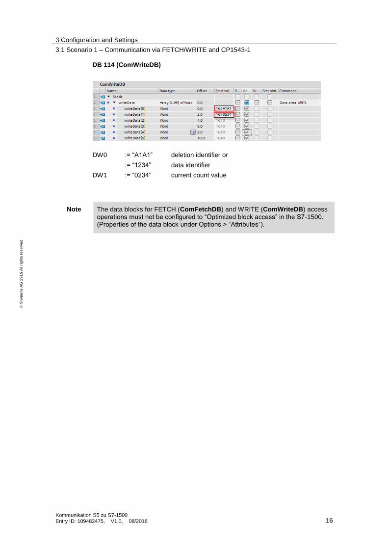
DB 114 (ComWriteDB)
DW0 := “A1A1” deletion identifier or
:= “1234” data identifier
DW1 := “0234” current count value
Note The data blocks for FETCH (ComFetchDB) and WRITE (ComWriteDB) access operations must not be configured to “Optimized block access” in the S7-1500. (Properties of the data block under Options > “Attributes”).

3 Configuration and Settings
3.1 Scenario 1 – Communication via FETCH/WRITE and CP1543-1
Kommunikation S5 zu S7-1500 Entry ID: 109482475, V1.0, 08/2016 17
S
iem
en
s A
G 2
91
6 A
ll ri
gh
ts r
ese
rve
d
3.1.3 Communication program SIMATIC S5
Overview
The following blocks contain the communication program of the S5-CPU. In this scenario, the S5 takes over the active part of the communication.
OB 1
Main
OB 21
Startup
FB40
HTB
SEND_ALL
HTB
RECV_ALL
COM_FETCH
_DB
COM_WRITE
_DB
DB 70
FET_WRI
User
blocks
Handling
blocks
Data blocks
OB 22
Startup HTB
SYNCHRON
FB 99
Takt
HTB FETCH
HTB SEND
Function
Via an active WRITE connection, a count value is sent cyclically from the SIMATIC S5 to the S7-1500 every second and then is requested again by the S7-1500 via a FETCH connection.
Description of the blocks
The following blocks contain the communication program of the S5-CPU.
Table 3-4
Block Symbol Description
OB 21 Startup_OB21 Startup OB (restart/warm start)
OB 22 Startup_OB22 Startup OB (network/cold start)
OB 1 Main User program for FETCH/WRITE function
FB 40 FET_WRI Time-triggered call of the FETCH and WRITE functions via S5 handling blocks (HTBs)
FB 99 Clock (1 sec) Clock generation 1 sec
FB244 HTB_SEND Handling block SEND (-All A-NR:= 0)
FB245 HTB_RECEIVE Handling block RECEIVE (-All A-NR:= 0)
FB246 HTB_FETCH Handling block FETCH
FB249 HTB_SYNCHRON Handling block SYNCHRON

3 Configuration and Settings
3.1 Scenario 1 – Communication via FETCH/WRITE and CP1543-1
Kommunikation S5 zu S7-1500 Entry ID: 109482475, V1.0, 08/2016 18
S
iem
en
s A
G 2
91
6 A
ll ri
gh
ts r
ese
rve
d
Block Symbol Description
DB 70 FET_WRI Parameter for the HTB FETCH/WRITE handling blocks (indirectly addressed)
DB 113 FETCH_DB Data area for read access (FETCH)
DB 114 WRITE_DB Data area for write access (WRITE)
In the SIMATIC S5-CPU, the active FETCH and WRITE functions are triggered independently of each other every second.
OB21/OB22 (STARTUP OBs)
The following functions are implemented in the startup of the SIMATIC S5-CPU:
The set interface (interface no. = 0) of the CP1430 TCP is initialized and synchronized via the handling block “HTB_Synchron” (FB 249).
An internal startup bit (M 199.0) and the initial count value are reset.
After each restart, a deletion identifier (sample = “A1A1”) is set in the FETCH data area (DB113). This deletion identifier has the effect that a count value in the WRITE data area (DB 114) is reset.
OB1 (cyclic OB)
The following functions are processed in the cyclic OB1 of the SIMATIC S5-CPU:
Call of the user communication block FET_WRI (FB 40) containing the active FETCH and WRITE functions. This example scenario 1 is started by setting an enable bit (M 130.5).
Call of the handling blocks SEND ALL and RECEIVE ALL for data transfer to the CP1430 TCP.
FB40 (FET_WRI)
The function block FB 40 contains the active FETCH and WRITE communication functions in which a simple simulation program demonstrates the exchange of data.
A restart of the communication is initiated via the startup bit M 199.0 (OB21/22).
Every second (FB99/M 152.0), a count value is written to the target DB of the S7-1500 CPU via a WRITE connection.
In the S7-1500, this count value is checked, incremented by +1, requested again from the S7-1500 with the next FETCH trigger in the S5-CPU and then stored in the FETCH_DB (DB 114).
After the value has been checked, it is incremented again by +1 and written to the S7-1500 via the WRITE connection in a new storage cycle.
A simple error analysis regarding the connection status is done by storing the indicator words and parameter error bytes. HTB_FETCH block: ANZW: MW70 PAFE: MB74 HTB_WRITE block: ANZW: MW75 PAFE: MB79

3 Configuration and Settings
3.1 Scenario 1 – Communication via FETCH/WRITE and CP1543-1
Kommunikation S5 zu S7-1500 Entry ID: 109482475, V1.0, 08/2016 19
S
iem
en
s A
G 2
91
6 A
ll ri
gh
ts r
ese
rve
d
FB99 (CLOCK)
The block generates a clock of 1 second for time-controlled triggering of the FETCH and WRITE jobs in the FET_WRI (FB40) block.
DB70 (FET_WRI)
The data block contains the parameters for indirect addressing of the active FETCH and WRITE functions. The data block with the indirect addressing is required in FB 40 for calling the HTB FETCH and SEND (R/W).
Table 3-5
Parameter area Start address Source parameter Destination parameter
FETCH parameter as of DW 0 Area to be read in the S7-1500 CPU (here DB 113, as of byte 0, length of 50 bytes)
Destination data area in the S5-CPU (here DB 113, as of byte 0, length of 50 bytes)
WRITE parameter as of DW 10 Data area to be read in the S5 (here DB 114, as of byte 0, length of 50 bytes)
Destination data area in the S7-CPU (here DB 114, as of byte 0, length of 50 bytes)
Figure 3-1
3.1.4 Connection configuration in the SIMATIC S7-1500
Configuration
For the passive FETCH and WRITE functions via the CP1543-1, no OUC connection has to be created in the TIA project. The hardware used and the network-side settings of the S7-1500 in TIA Portal are structured identically for all scenarios. This means that both a S7-1500 CPU and a CP1543-1 have to be set up in configured and networked condition.
To do this, proceed as follows:
3 Configuration and Settings
3.1 Scenario 1 – Communication via FETCH/WRITE and CP1543-1
Kommunikation S5 zu S7-1500 Entry ID: 109482475, V1.0, 08/2016 20
S
iem
en
s A
G 2
91
6 A
ll ri
gh
ts r
ese
rve
d
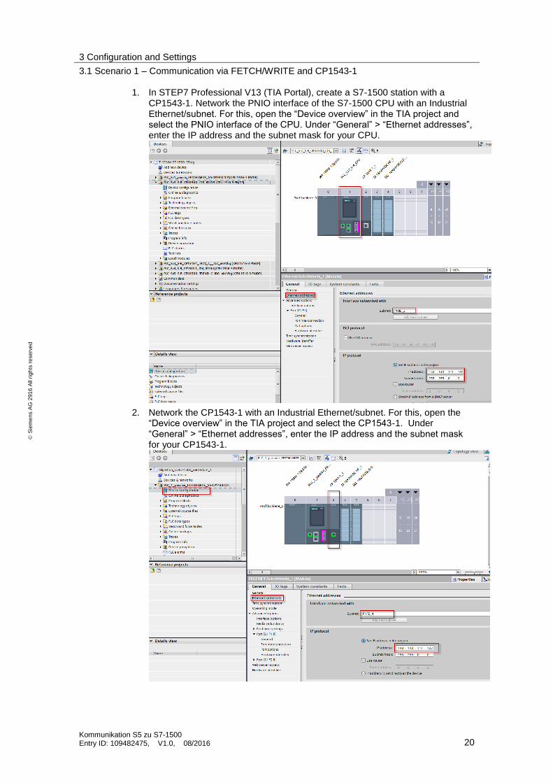
1. In STEP7 Professional V13 (TIA Portal), create a S7-1500 station with a CP1543-1. Network the PNIO interface of the S7-1500 CPU with an Industrial Ethernet/subnet. For this, open the “Device overview” in the TIA project and select the PNIO interface of the CPU. Under “General” > “Ethernet addresses”, enter the IP address and the subnet mask for your CPU.
2. Network the CP1543-1 with an Industrial Ethernet/subnet. For this, open the “Device overview” in the TIA project and select the CP1543-1. Under “General” > “Ethernet addresses”, enter the IP address and the subnet mask for your CP1543-1.

3 Configuration and Settings
3.1 Scenario 1 – Communication via FETCH/WRITE and CP1543-1
Kommunikation S5 zu S7-1500 Entry ID: 109482475, V1.0, 08/2016 21
S
iem
en
s A
G 2
91
6 A
ll ri
gh
ts r
ese
rve
d
3. In the “General” tab, go to “Options” > “FETCH/WRITE configuration” to enable the “FETCH/WRITE configuration” option and disable the S7 addressing mode [S5 addressing mode] in the TSAP list.
4. Enter the local TSAPs for the FETCH and WRITE services respectively via the ISO-on-TCP connection. The TSAPs are available in the configuration of the CP1430 TCP (see chapter 3.1.5).
TSAP “CP1543-F”: TSAP for the S5 CP1430 TCP FETCH connection TSAP “CP1543-W”: TSAP for the S5 CP1430 TCP SEND (R/W) connection

3 Configuration and Settings
3.1 Scenario 1 – Communication via FETCH/WRITE and CP1543-1
Kommunikation S5 zu S7-1500 Entry ID: 109482475, V1.0, 08/2016 22
S
iem
en
s A
G 2
91
6 A
ll ri
gh
ts r
ese
rve
d
5. In the “Device view” of the S7-1500 station, select the CPU. The properties of the CPU are displayed in the inspector window.
6. In the “General” tab, go to “Protection” and enable under “Access level” the function “Permit with PUT/GET communication from remote partner (PLC, HMI, OPC ...)”.
3 Configuration and Settings
3.1 Scenario 1 – Communication via FETCH/WRITE and CP1543-1
Kommunikation S5 zu S7-1500 Entry ID: 109482475, V1.0, 08/2016 23
S
iem
en
s A
G 2
91
6 A
ll ri
gh
ts r
ese
rve
d
3.1.5 Connection configuration in the CP1430 TCP (SIMATIC S5)
Introduction
The following settings are used to establish an “active” FETCH and WRITE
connection to the CP1543-1.
The following explanations regarding the configuration of the CP1430 TCP refer to example scenario 1 (FETCH/WRITE).
Note The CP1430 TCP configuration file “TCP1430A.TCP” already contains the complete configurations for all 6 example scenarios. Thus, after loading the CP1430 file, all other connections are also available “offline” in the CP1430 TCP.
Configuration
The FETCH/WRITE connection in the CP1430 TCP is created using the “SINEC NCM COM 1430 TCP” configuration tool.
Note The "SINEC NCM COM 1430" configuration tool is an additional software that is integrated in STEP 5 to configure the CP1430 TCP. This software is not included in the standard STEP 5 package and must be installed additionally.
To do this, proceed as follows:
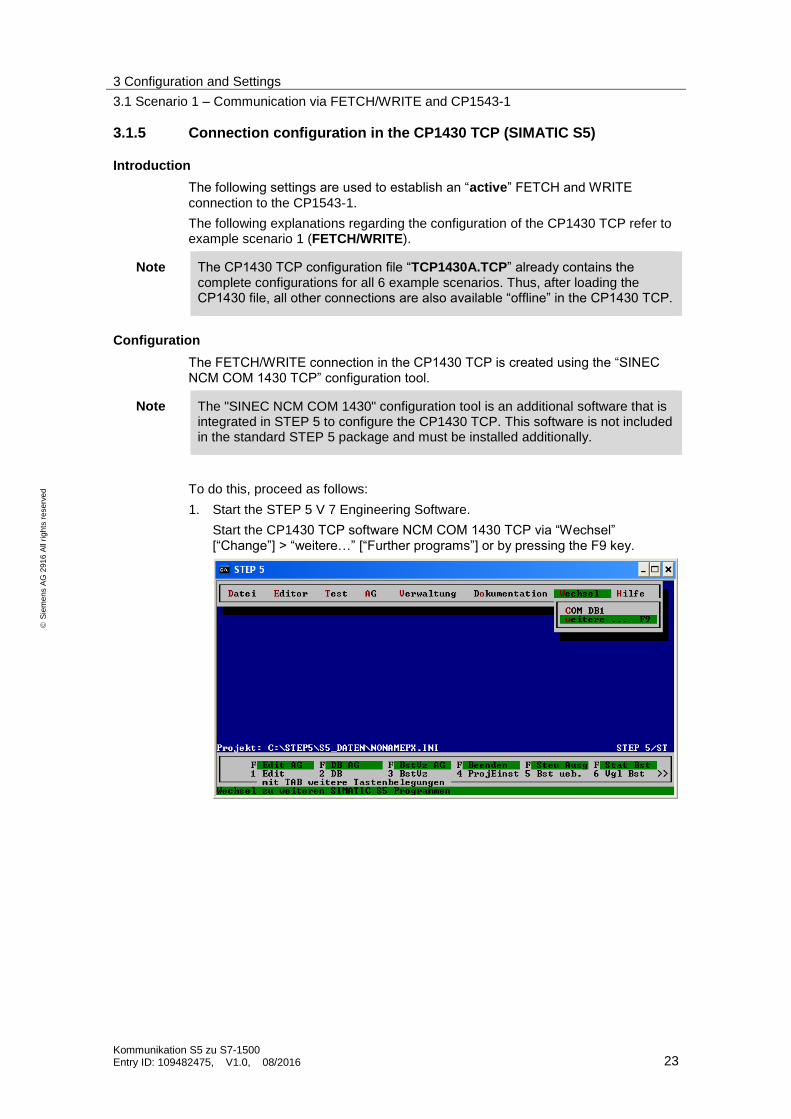
1. Start the STEP 5 V 7 Engineering Software.
Start the CP1430 TCP software NCM COM 1430 TCP via “Wechsel” [“Change”] > “weitere…” [“Further programs”] or by pressing the F9 key.

3 Configuration and Settings
3.1 Scenario 1 – Communication via FETCH/WRITE and CP1543-1
Kommunikation S5 zu S7-1500 Entry ID: 109482475, V1.0, 08/2016 24
S
iem
en
s A
G 2
91
6 A
ll ri
gh
ts r
ese
rve
d
2. Start the configuration tool “NCM package COM 1430 TCP”.
3. Select “File” > “Select” to get to the “Basic Settings”.
Here, enter the CP1430 TCP project file name “TCP1430A.TCP” (1) from the download of this project. Click on “OK” (F7) to confirm the settings.
1

3 Configuration and Settings
3.1 Scenario 1 – Communication via FETCH/WRITE and CP1543-1
Kommunikation S5 zu S7-1500 Entry ID: 109482475, V1.0, 08/2016 25
S
iem
en
s A
G 2
91
6 A
ll ri
gh
ts r
ese
rve
d
4. Initialize the CP via the menu "Edit > CP_Init" (1)
5. As shown in the figure, enter the MAC address of the CP under (1) “MAC address (HEX)” and the basic interface no. 0 under (2) “Base SSNR”. Click on “OK” (F7) to confirm the settings.
1
2
1

3 Configuration and Settings
3.1 Scenario 1 – Communication via FETCH/WRITE and CP1543-1
Kommunikation S5 zu S7-1500 Entry ID: 109482475, V1.0, 08/2016 26
S
iem
en
s A
G 2
91
6 A
ll ri
gh
ts r
ese
rve
d
6. Now, go to the “TCP/IP Init” screen via “Edit” >“TCP/IP Init” (1).
7. Enter the local host name (ASCII) under (1), your own TCP/IP address (dec.) under (2), the default gateway under (3) and the netmask (dec.) under (4).
Note The configured IP address has to be selected according to the connections created for the S7-1500/ CP1543-1.
1
2
3
4
1

3 Configuration and Settings
3.1 Scenario 1 – Communication via FETCH/WRITE and CP1543-1
Kommunikation S5 zu S7-1500 Entry ID: 109482475, V1.0, 08/2016 27
S
iem
en
s A
G 2
91
6 A
ll ri
gh
ts r
ese
rve
d
8. To do this, go to “Edit” >“Connections” and select the option “Transport Connection (TCP/RFC1006)” (1).
Now, enter the following parameters in the input window.
9. For this example, two ISO-on-TCP connections (transport connections RFC 1006) are required. For each of them, the job types “FETCH” and “WRITE” have to be set respectively. Both connections are configured as active connections.
For the FETCH connection, set the job number ANR “113” under (1), the job type “FETCH” under (2) and the R/W identifier to “Y” under (3). Under “Transport addresses” (4), enter the local TSAP “CP1543-F” and under (5) the remote TSAP “CP1543-F”. Under the “Active/passive” parameter (6),
set the way the connection is established to “A” (active).
Click on “OK” (F7) to confirm the settings.
1
2
3
4
5
6
1

3 Configuration and Settings
3.1 Scenario 1 – Communication via FETCH/WRITE and CP1543-1
Kommunikation S5 zu S7-1500 Entry ID: 109482475, V1.0, 08/2016 28
S
iem
en
s A
G 2
91
6 A
ll ri
gh
ts r
ese
rve
d
10. Create a second connection as WRITE connection. Set the job number ANR to “114” under (1), the job type to “SEND” under (2) and the read/write identifier to “Y” under (3). Under “Transport addresses” (4), enter the local TSAP “CP1543-W” and under (5) the remote TSAP “CP1543-W”. Under the “Active/passive” parameter (6),
set the way the connection is established to “A” (active).
Click on “OK” (F7) to confirm the settings.
Note In the transport configuration, a “WRITE” connection is configured as job type “SEND” with the R/W identifier being set to “Y”!
1
2
3
4
5
6

3 Configuration and Settings
3.2 Scenario 2a – Communication via parameterized OUC (single instructions) and internal CPU interface
Kommunikation S5 zu S7-1500 Entry ID: 109482475, V1.0, 08/2016 29
S
iem
en
s A
G 2
91
6 A
ll ri
gh
ts r
ese
rve
d
3.2 Scenario 2a – Communication via parameterized OUC (single instructions) and internal CPU interface
3.2.1 Mode of operation
Overview
In this scenario, the SIMATIC S7-1500 CPU actively establishes an ISO-on-TCP connection to the S5 via the CP1430 TCP using the integrated PROFINET interface.
On the S7-1500 CPU end, a parameterized connection configuration is used. The data are sent and received bidirectionally via the OUC blocks TSEND and TRCV.
For this connection, the SIMATIC S5 uses the standard handling blocks (HTB) SYNCHRON/SEND/RECEIVE. In the CP1430 TCP, the ISO-on-TCP connection in the SIMATIC S5 is configured as a “passive” duplex connection.

3 Configuration and Settings
3.2 Scenario 2a – Communication via parameterized OUC (single instructions) and internal CPU interface
Kommunikation S5 zu S7-1500 Entry ID: 109482475, V1.0, 08/2016 30
S
iem
en
s A
G 2
91
6 A
ll ri
gh
ts r
ese
rve
d
Sequence of the parameterized OUC communication via single instructions
The figure below schematically shows the connection established and the data flow between SIMATIC S5 and SIMATIC S7-1500 using the parameterized SEND and
RECEIVE mechanism via ISO-on-TCP.
Flow chart
OB1
SIMATIC S5 CPU SIMATIC S7-1500 CPU
SEND job trigger
CP1430
TCP
SEND
RECEIVE
Data
Acknowledgment
Value 1
Value 2
…
…
…
…
Value 1
Value 2
…
…
…
…
Value 1
Value 2
…
…
…
Value 1
Value 2
…
…
…
FB40
HTB
SEND
HTB
RECEIVE
RECEIVE
ALL
SEND
ALL
CPU 1500
PNIO SSConnection
configurationConnection
configuration1
2
3
TRCV
TSEND
Conn.establish.
CR
CC
HTB
SYNCRON
Acknowledgment
A_NR
TSAP 1SEND/RCV
…
ID 105
TSAP 1SEND/RCV
…
OB1
RECEIVE
SEND
No. Process
1 Startup of the SIMATIC S5 and synchronization with the CP1430 TCP.
2 The cyclic processing of the HTB RECEIVE block in the S5-CPU ensures readiness to receive between the CPU and the CP1430 TCP. The data are transferred from the CP1430 TCP to the data block of the SIMATIC S5-CPU via the RECEIVE ALL handling block.
3 The SIMATIC S5 transfers the SEND job to the CP1430 TCP via HTB SEND. The data are transferred from the SIMATIC S5-CPU (data block) to the CP1430 TCP via the SEND ALL handling block.
4 The received data are transferred to the S7-1500 CPU via the cyclic processing of the OUC block TRCV. If the data have been received successfully, this is shown by a positive acknowledgment and signaled at block parameter NDR. Otherwise, a negative acknowledgment will be sent for the job.
5 A SEND job is sent from the S7-1500 CPU to the SIMATIC S5 via the OUC block TSEND. In this scenario, the block sends a job to the SIMATIC S5 CP1430 TCP every second. In the S5-CPU, the data are transferred via the standard HTBs RECEIVE and RECEIVE ALL.

3 Configuration and Settings
3.2 Scenario 2a – Communication via parameterized OUC (single instructions) and internal CPU interface
Kommunikation S5 zu S7-1500 Entry ID: 109482475, V1.0, 08/2016 31
S
iem
en
s A
G 2
91
6 A
ll ri
gh
ts r
ese
rve
d
3.2.2 Communication program in the SIMATIC S7-1500
Overview
The following blocks contain the communication program in the S7-1500 CPU.
RecvData
SendData
OB 1
Main
OB 100
Startup
User
blocks
TSEND
TRCV
OUC system
blocks
FB4
ConnManager
ParamID105
Function
The function block FB4 is used to call the OUC communication blocks TSEND and TRCV. In this variant of OUC communication, the connection is established by an “actively” parameterized ISO-on-TCP connection. After having restarted the S7-1500 CPU, the connection will be established automatically.
The data are sent and received bidirectionally via the OUC blocks TSEND and TRCV. The data are sent every 0.5 seconds (via clock memory bit). To detect the ongoing data communication in the S7-1500, a count value is received by the SIMATIC S5, mirrored and sent back. For visualization, the received count value is transferred to the output area AB0.
Description of the blocks
Block Symbol Description
OB 100 Startup Startup OB
OB 1 Main Cyclic OB
FB 4 ConnManagerParamID105
Management of connection ID 105
DB 19 InstConnManagerParamID105
Instance DB of FB 4 (send/receive data area)
DB 16 InstTSENDParamID105 Instance DB TSEND ID 105
DB 17 InstTRCVParamID105 Instance DB TRCV ID 105
3 Configuration and Settings
3.2 Scenario 2a – Communication via parameterized OUC (single instructions) and internal CPU interface
Kommunikation S5 zu S7-1500 Entry ID: 109482475, V1.0, 08/2016 32
S
iem
en
s A
G 2
91
6 A
ll ri
gh
ts r
ese
rve
d
OB 100 (startup OB)
After having restarted the S7-1500 CPU, a start identifier is set for automatically establishing a connection to the SIMATIC S5.
OB 1 (cyclic OB)
Via the enable input “E 0.1” (abortReq), the OB1 calls FB 4 which manages the OUC communication.
FB 4 (TSEND/TRCV management)
In FB4, the data are received by the SIMATIC S5 via the cyclically processed OUC block TRCV. To visualize the ongoing communication, a count value is copied to an output area (AB 0) of the S7-1500.
The count value received by the SIMATIC S5 is located in the instance data block of FB4 in the static tag “statRcvData” and is copied to the send area of the instance data block “statSendData” for sending. Via a send enable “E0.1” (abortReq), these data are mirrored and sent back to the SIMATIC S5 every 500 ms.
In addition, the received data are checked.
- The data are cyclically checked for a deletion identifier (“A1A1”) being available. In case of a match, the count value is reset.
- The ongoing communication of the OUC communication is visualized via the output area of the S7-1500.

3 Configuration and Settings
3.2 Scenario 2a – Communication via parameterized OUC (single instructions) and internal CPU interface
Kommunikation S5 zu S7-1500 Entry ID: 109482475, V1.0, 08/2016 33
S
iem
en
s A
G 2
91
6 A
ll ri
gh
ts r
ese
rve
d
3.2.3 Communication program SIMATIC S5
Overview
The following blocks contain the communication program of the S5-CPU. In this scenario, the S5 sends and receives data via a passive ISO-on-TCP connection.
The connection is established from the S7-1500.
OB 1
Main
OB 21
Startup
FB33
HTB
SEND_ALL
HTB
RECV_ALL
SEND_DB
RECV_DB
User
blocks
Handling
blocks
Data blocks
OB 22
Startup HTB
SYNCHRON
HTB SEND
HTB RECV
Function
Via the connection actively established by the S7-1500 CPU, data are sent bidirectionally with a count value from the SIMATIC S5 to the S7-1500 every second. From there, this count value is mirrored and sent back. After the data have been received, this count value is increased by +1 and sent again.
In case of the SIMATIC S5 CPU being restarted, a deletion identifier is sent and the count value is reset.
Description of the blocks
The following blocks contain the communication program of the S5-CPU.
Table 3-6
Block Symbol Description
OB 21 Startup_OB21 Startup OB (restart/warm start)
OB 22 Startup_OB22 Startup OB (network/cold start)
OB 1 Main User program call of FB 33 and of the HTBs

3 Configuration and Settings
3.2 Scenario 2a – Communication via parameterized OUC (single instructions) and internal CPU interface
Kommunikation S5 zu S7-1500 Entry ID: 109482475, V1.0, 08/2016 34
S
iem
en
s A
G 2
91
6 A
ll ri
gh
ts r
ese
rve
d
Block Symbol Description
SEND/RECEIVE ALL
FB 33 ID105_S7 Time-triggered call of the send and receive functions via S5 handling blocks (HTBs). Increase of count value in the data
FB 244 HTB_SEND Handling block SEND-All (A-NR:= 0)
FB 245 HTB_RECEIVE Handling block RECEIVE-All (A-NR:= 0)
FB 249 HTB_SYNCHRON Handling block SYNCHRON
DB 90 - Data area for sending
DB 95 - Data area for receiving
OB21/OB22 (STARTUP OBs)
The following functions are executed in the startup of the SIMATIC S5-CPU:
The set interface (interface no. = 0) of the CP1430 TCP is initialized and synchronized via the handling block “HTB_Synchron” (FB 249).
An internal startup bit (M 184.5) resets the initial count value.
OB1 (cyclic OB)
The following functions are processed in the cyclic OB1 of the SIMATIC S5-CPU:
This example scenario 2a is started by setting an enable bit (M 130.3).
Call of the user communication block ID105_S7 (FB 33) which uses a time trigger to call the send and receive functions via S5 handling blocks (HTBs) and increments the count values in the data area.
Call of the handling blocks SEND ALL and RECEIVE ALL for data transfer to the CP1430 TCP.
FB33 (ID105_S7)
The function block FB 33 contains the time-triggered call of the send and receive functions in which a simple simulation program demonstrates the exchange of data.
A restart of the communication is initiated via the startup bit M 184.5 (OB21/22).
Every second (clock memory bit), a count value (in DB90) is sent to the S7-1500 CPU via the ISO-on-TCP connection.
After the data have been received, this count value is checked in the S7-1500, incremented by +1 and sent back to the SIMATIC S5 at the next send trigger of the S7-1500. The data received by the SIMATIC S5 are transferred to DB95.
A simple error analysis regarding the connection status is done by storing the indicator words and parameter error bytes. HTB_SEND block: ANZW: MW90 PAFE: MB94 HTB_RECEIVE block: ANZW: MW95 PAFE: MB99

3 Configuration and Settings
3.2 Scenario 2a – Communication via parameterized OUC (single instructions) and internal CPU interface
Kommunikation S5 zu S7-1500 Entry ID: 109482475, V1.0, 08/2016 35
S
iem
en
s A
G 2
91
6 A
ll ri
gh
ts r
ese
rve
d
3.2.4 Connection configuration in the S7-1500 CPU
Prerequisite
All network-side settings of the S7-1500 CPU and of the CP1543-1 used in TIA Portal are structured identically for all scenarios.
For the corresponding configuration steps, proceed as described in chapter “3.1.4– Connection configuration in the SIMATIC S7-1500” steps 1 and 2 of scenario 1 and complete the configuration following the steps described in the next section.
Configuration
In this scenario 2a, the connection is parameterized via a dialog in TIA Portal. The required connection parameter are pre-assigned and set up via a connection table in the S7-1500 CPU.
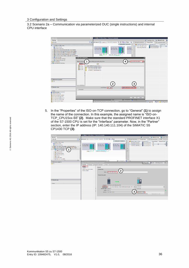
3. In the “Device configuration” (1) of the “PLC_Sz2..”, open the “Network view” (2). In the “Connections” tab (3), select your CPU and use the “Insert” menu item or right-click to add a new connection.
4. Now, under “Unspecified” (1), enter “105” as “Local ID” (2). Tick the “Establish active connection” option to enable this connection property. Under “Type” (4), select “ISO-on-TCP connection” and confirm your settings by clicking the “Close” button.
1
2 3
3 Configuration and Settings
3.2 Scenario 2a – Communication via parameterized OUC (single instructions) and internal CPU interface
Kommunikation S5 zu S7-1500 Entry ID: 109482475, V1.0, 08/2016 36
S
iem
en
s A
G 2
91
6 A
ll ri
gh
ts r
ese
rve
d
5. In the “Properties” of the ISO-on-TCP connection, go to “General” (1) to assign the name of the connection. In this example, the assigned name is “ISO-on-TCP_CPU15xx-S5” (2). Make sure that the standard PROFINET interface X1 of the S7-1500 CPU is set for the “Interface” parameter. Now, in the “Partner” section, enter the IP address (IP: 140.140.111.104) of the SIMATIC S5 CP1430 TCP (3).
1
2 3
4
1
2
3

3 Configuration and Settings
3.2 Scenario 2a – Communication via parameterized OUC (single instructions) and internal CPU interface
Kommunikation S5 zu S7-1500 Entry ID: 109482475, V1.0, 08/2016 37
S
iem
en
s A
G 2
91
6 A
ll ri
gh
ts r
ese
rve
d
6. Under “Address details”, enter the local (1) and remote (2) TSAPs for the ISO-on-TCP connection. The TSAPs have been taken from the configuration of the CP1430 TCP (see chapter 3.1.5) as follows. local TSAP: “CPU_150a” remote TSAP: “CPU_150a”
7. After having completed the settings for this ISO-on-TCP connection, the project has to be compiled again. To do this, select the S7 station, store it and thus compile this S7 station.
3.2.5 Connection configuration in the CP1430 TCP (SIMATIC S5)
Introduction
Make the following settings to establish a “passive” ISO-on-TCP DUPLEX
connection to a S7-1500 CPU with an integrated PROFINET interface.
Note The CP1430 TCP configuration file “TCP1430A.TCP” already contains the complete configurations for all 6 example scenarios. Thus, after loading the CP1430 file, all other connections are also available “offline” in the CP1430 TCP.
Configuration
The “passive” connection for scenario 2a in the CP1430 TCP is created using the “SINEC NCM COM 1430 TCP” configuration tool.
Note The "SINEC NCM COM 1430" configuration tool is an additional software that is integrated in STEP 5 to configure the CP1430 TCP. This software is not included in the standard STEP 5 package and must be installed additionally.
The connection configuration is largely identical to chapter 3.1.5 Connection configuration in the CP1430 TCP (SIMATIC S5)”. Follow the steps 1 to 8 described in that chapter and complete the configuration following the steps described below.
1 2

3 Configuration and Settings
3.2 Scenario 2a – Communication via parameterized OUC (single instructions) and internal CPU interface
Kommunikation S5 zu S7-1500 Entry ID: 109482475, V1.0, 08/2016 38
S
iem
en
s A
G 2
91
6 A
ll ri
gh
ts r
ese
rve
d
9. For this example (scenario 2a), two ISO-on-TCP connections (transport connections RFC 1006) are required. To set up the “passive” connection, the job “1 of 2” must be parameterized as a RECEIVE type. In the subsequent mask of the job, the TSAP “CPU_150a” is entered. The job “2 of 2” must be set up as a SEND job
type.
Enter
– for the passive ISO-on-TCP connection under (1) the job number ANR “33”,
– under (2) the job type: “RECEIVE”,
– under “Transport addresses” (3) the local TSAP “CPU_150a” and under (4) the remote TSAP “CPU_150a”,
– under “Number of jobs per TSAP” (5) “1 of 2”,
– under the “Active/passive” parameter (6) the connection establishment “P” (passive).
1 2
3 4
5
6

3 Configuration and Settings
3.2 Scenario 2a – Communication via parameterized OUC (single instructions) and internal CPU interface
Kommunikation S5 zu S7-1500 Entry ID: 109482475, V1.0, 08/2016 39
S
iem
en
s A
G 2
91
6 A
ll ri
gh
ts r
ese
rve
d
10. Now, create job 2 of 2 with “+1” (F1).
Enter
– under (1) the job number ANR with “133”,
– under (2) the job type: “SEND”.
– Click on “OK” (F7) to confirm the settings.
1 2
3 Configuration and Settings
3.3 Scenario 2b – Communication via programmed OUC (single instructions) and internal CPU interface
Kommunikation S5 zu S7-1500 Entry ID: 109482475, V1.0, 08/2016 40
S
iem
en
s A
G 2
91
6 A
ll ri
gh
ts r
ese
rve
d
3.3 Scenario 2b – Communication via programmed OUC (single instructions) and internal CPU interface
3.3.1 Mode of operation
Overview
In this scenario, the SIMATIC S5 actively establishes an ISO-on-TCP connection
to the S7-1500 CPU via the CP1430 TCP using the internal PROFINET interface.
On the S7-1500 CPU end, the programmed connection is set up passively via the OUC block TCON by the user program and is available for establishing the connection of the partner. The data then are sent and received via the blocks TSEND and TRCV.
For this connection, the SIMATIC S5 uses the standard handling blocks SYNCHRON/SEND/RECEIVE. In the CP1430 TCP, the ISO-on-TCP connection in the SIMATIC S5 is configured as an “active” duplex connection.
3 Configuration and Settings
3.3 Scenario 2b – Communication via programmed OUC (single instructions) and internal CPU interface
Kommunikation S5 zu S7-1500 Entry ID: 109482475, V1.0, 08/2016 41
S
iem
en
s A
G 2
91
6 A
ll ri
gh
ts r
ese
rve
d
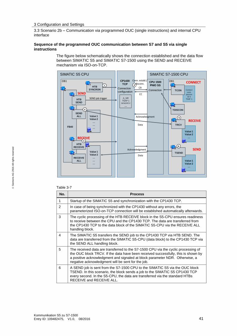
Sequence of the programmed OUC communication between S7 and S5 via single
instructions
The figure below schematically shows the connection established and the data flow between SIMATIC S5 and SIMATIC S7-1500 using the SEND and RECEIVE mechanism via ISO-on-TCP.
Flow chart
OB1
SIMATIC S5 CPU SIMATIC S7-1500 CPU
SEND job trigger
CP1430
TCP
SEND
RECEIVE
Data
Data
Acknowledgment
Value 1
Value 2
…
Value 1
Value 2
…
Value 1
Value 2
…
…
…
Value 1
Value 2
…
…
…
FB40
HTB
SEND
HTB
RECEIVE
RECEIVE
ALL
SEND
ALL
CPU 1500
PNIO SSConnection
configurationConnection
1 2
3
TRCV
TSEND
Conn. establ./disconn.
CR
CC
HTB
SYNCRON
Acknowledgment
A_NRTSAP 1
SEND/RCV
…
Connect
conn.
passive
ID 5
TSAP 1
TCON
4
5
SEND
RECEIVE
OB1 CONNECT
6
TDISCON
Table 3-7
No. Process
1 Startup of the SIMATIC S5 and synchronization with the CP1430 TCP.
2 In case of being synchronized with the CP1430 without any errors, the parameterized ISO-on-TCP connection will be established automatically afterwards.
3 The cyclic processing of the HTB RECEIVE block in the S5-CPU ensures readiness to receive between the CPU and the CP1430 TCP. The data are transferred from the CP1430 TCP to the data block of the SIMATIC S5-CPU via the RECEIVE ALL handling block.
4 The SIMATIC S5 transfers the SEND job to the CP1430 TCP via HTB SEND. The data are transferred from the SIMATIC S5-CPU (data block) to the CP1430 TCP via the SEND ALL handling block.
5 The received data are transferred to the S7-1500 CPU via the cyclic processing of the OUC block TRCV. If the data have been received successfully, this is shown by a positive acknowledgment and signaled at block parameter NDR. Otherwise, a negative acknowledgment will be sent for the job.
6 A SEND job is sent from the S7-1500 CPU to the SIMATIC S5 via the OUC block TSEND. In this scenario, the block sends a job to the SIMATIC S5 CP1430 TCP every second. In the S5-CPU, the data are transferred via the standard HTBs RECEIVE and RECEIVE ALL.

3 Configuration and Settings
3.3 Scenario 2b – Communication via programmed OUC (single instructions) and internal CPU interface
Kommunikation S5 zu S7-1500 Entry ID: 109482475, V1.0, 08/2016 42
S
iem
en
s A
G 2
91
6 A
ll ri
gh
ts r
ese
rve
d
3.3.2 Communication program in the SIMATIC S7-1500
Overview
The following blocks contain the communication program in the S7-1500 CPU.
RecvData
SendData
OB 1
Main
OB 100
Startup
FB 5
ConnManager
ParamID5
User
blocks
TCON
TSEND
TDISCON
TRCV
OUC system
blocks
Function
A programmed OUC communication is set up passively by calling the OUC communication block TCON. In this case, the connection is established actively from the SIMATIC S5. As soon as the connection is established, the data are exchanged via the OUC communication blocks TSEND and TRCV.
To detect the ongoing data communication in the S7-1500, a count value is received by the SIMATIC S5, mirrored and sent back. For visualization, the received count value is transferred to the output area AB0.
Description of the blocks
Table 3-8
Block Symbol Description
OB 100 Startup Startup OB
OB 1 Main Cyclic OB
FB 5 ConnManagerProgID5 Management of connection ID 5
DB 29 InstConnManagerProgID5 Instance DB of FB 4 (+send/receive data area)
DB 25 ConnectParamID5 Connect parameter ID5
DB 24 InstTCONID5 Instance DB TCON ID 5
DB 28 InstTDISCONID5 Instance DB TDISCON ID 5
DB 26 InstTSENDID5 Instance DB TSEND ID 5
DB 27 InstTRCVID5 Instance DB TRCV ID 5

3 Configuration and Settings
3.3 Scenario 2b – Communication via programmed OUC (single instructions) and internal CPU interface
Kommunikation S5 zu S7-1500 Entry ID: 109482475, V1.0, 08/2016 43
S
iem
en
s A
G 2
91
6 A
ll ri
gh
ts r
ese
rve
d
OB 100 (startup OB)
After having restarted the S7-1500 CPU, the connect enable bit “startConnID5” is reset. It has the effect that a passively programmed connection is set up in the cyclic program.
OB 1 (cyclic OB)
Via the enable input “E 0.2” (abortReq), the OB1 calls FB 5 which manages the OUC communication.
FB 5 (TSEND/TRCV management)
In FB 5, it is checked via the connect enable bit whether the CPU is restarted. If this is the case, the passive ISO-on-TCP connection is set up via the OUC block TCON.
If the connection has been established successfully, the data are received by the SIMATIC S5 via the cyclically called OUC communication block TRCV. To visualize the ongoing communication, a count value is copied to an output area (AB 0) of the S7-1500.
The count value received by the SIMATIC S5 is located in the instance data block of FB5 in the static tag “statRcvData” and is copied to the send area of the instance data block “statSendData” for sending.
Via a send enable “E0.1”, these data are mirrored and sent back to the SIMATIC S5 every 500 ms.
In addition, the received data are checked.
- The data are cyclically checked for a deletion identifier (“A1A1”) being available. In case of a match, the count value is reset.
- The ongoing communication of the OUC communication is visualized via the output area of the S7-1500.

3 Configuration and Settings
3.3 Scenario 2b – Communication via programmed OUC (single instructions) and internal CPU interface
Kommunikation S5 zu S7-1500 Entry ID: 109482475, V1.0, 08/2016 44
S
iem
en
s A
G 2
91
6 A
ll ri
gh
ts r
ese
rve
d
3.3.3 Communication program SIMATIC S5
Overview
The following blocks contain the communication program of the S5-CPU. In this scenario, the S5 sends and receives data via an active ISO-on-TCP connection.
The connection is established from the SIMATIC S5.
OB 1
Main
OB 21
Startup
FB34
HTB
SEND_ALL
HTB
RECV_ALL
SEND_DB
RECV_DB
User
blocks
Handling
blocks
Data blocks
OB 22
Startup HTB
SYNCHRON
HTB SEND
HTB RECV
Function
Via the connection actively established by the SIMATIC S5, data are sent bidirectionally with a count value to the S7-1500 every second. From there, this count value is mirrored and sent back. After the data have been received, this count value is increased by +1 and sent again.
In case of the SIMATIC S5 CPU being restarted, a deletion identifier is sent to the S7-1500 and the count value is reset.
Description of the blocks
The following blocks contain the communication program of the S5-CPU.
Table 3-9
Block Symbol Description
OB 21 Startup_OB21 Startup OB (restart/warm start)
OB 22 Startup_OB22 Startup OB (network/cold start)
OB 1 Main User program call of FB 34 and of the HTBs SEND/RECEIVE ALL
FB 34 ID5_S7 Time-triggered call of the send and receive
3 Configuration and Settings
3.3 Scenario 2b – Communication via programmed OUC (single instructions) and internal CPU interface
Kommunikation S5 zu S7-1500 Entry ID: 109482475, V1.0, 08/2016 45
S
iem
en
s A
G 2
91
6 A
ll ri
gh
ts r
ese
rve
d
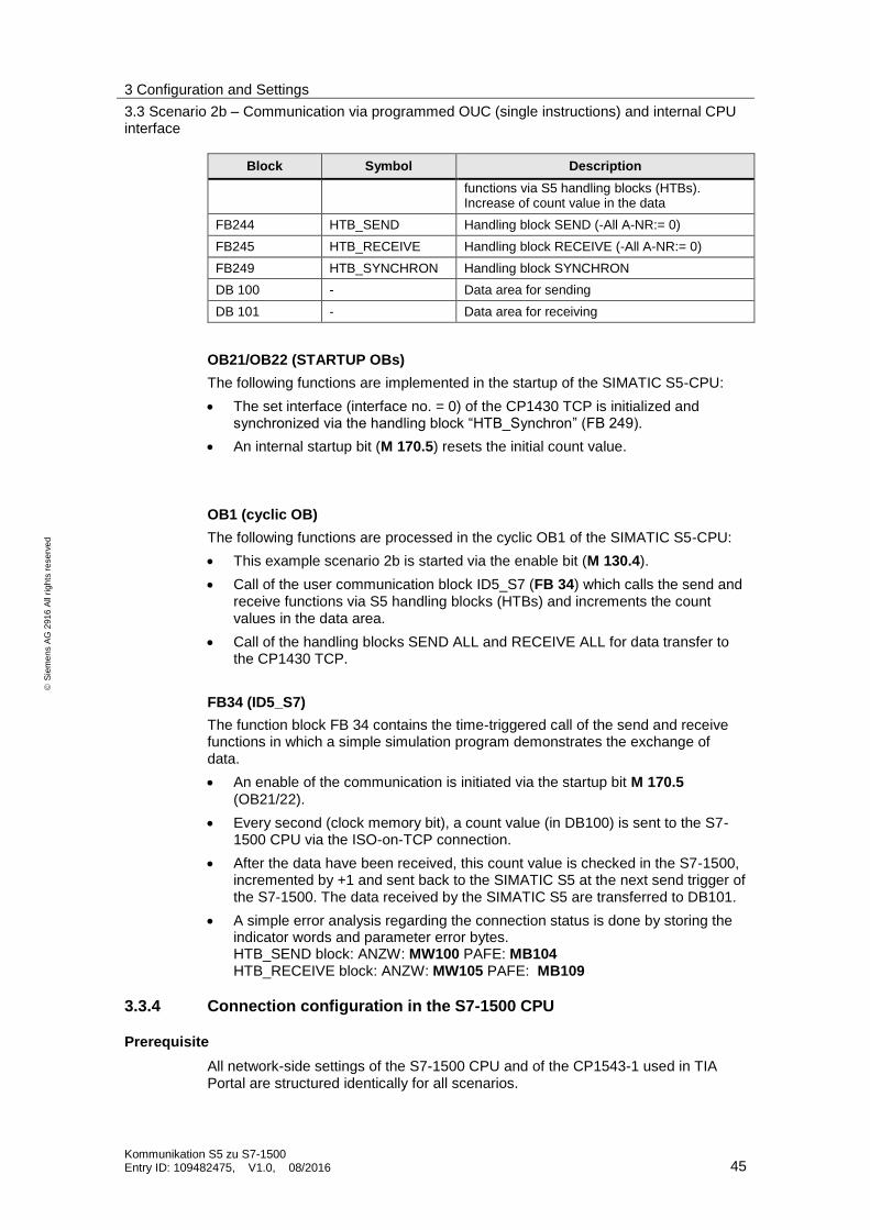
Block Symbol Description
functions via S5 handling blocks (HTBs). Increase of count value in the data
FB244 HTB_SEND Handling block SEND (-All A-NR:= 0)
FB245 HTB_RECEIVE Handling block RECEIVE (-All A-NR:= 0)
FB249 HTB_SYNCHRON Handling block SYNCHRON
DB 100 - Data area for sending
DB 101 - Data area for receiving
OB21/OB22 (STARTUP OBs)
The following functions are implemented in the startup of the SIMATIC S5-CPU:
The set interface (interface no. = 0) of the CP1430 TCP is initialized and synchronized via the handling block “HTB_Synchron” (FB 249).
An internal startup bit (M 170.5) resets the initial count value.
OB1 (cyclic OB)
The following functions are processed in the cyclic OB1 of the SIMATIC S5-CPU:
This example scenario 2b is started via the enable bit (M 130.4).
Call of the user communication block ID5_S7 (FB 34) which calls the send and receive functions via S5 handling blocks (HTBs) and increments the count values in the data area.
Call of the handling blocks SEND ALL and RECEIVE ALL for data transfer to the CP1430 TCP.
FB34 (ID5_S7)
The function block FB 34 contains the time-triggered call of the send and receive functions in which a simple simulation program demonstrates the exchange of data.
An enable of the communication is initiated via the startup bit M 170.5
(OB21/22).
Every second (clock memory bit), a count value (in DB100) is sent to the S7-1500 CPU via the ISO-on-TCP connection.
After the data have been received, this count value is checked in the S7-1500, incremented by +1 and sent back to the SIMATIC S5 at the next send trigger of the S7-1500. The data received by the SIMATIC S5 are transferred to DB101.
A simple error analysis regarding the connection status is done by storing the indicator words and parameter error bytes. HTB_SEND block: ANZW: MW100 PAFE: MB104 HTB_RECEIVE block: ANZW: MW105 PAFE: MB109
3.3.4 Connection configuration in the S7-1500 CPU
Prerequisite
All network-side settings of the S7-1500 CPU and of the CP1543-1 used in TIA Portal are structured identically for all scenarios.

3 Configuration and Settings
3.3 Scenario 2b – Communication via programmed OUC (single instructions) and internal CPU interface
Kommunikation S5 zu S7-1500 Entry ID: 109482475, V1.0, 08/2016 46
S
iem
en
s A
G 2
91
6 A
ll ri
gh
ts r
ese
rve
d
For the corresponding configuration steps, proceed as described in chapter “3.1.4– Connection configuration in the SIMATIC S7-1500” steps 1 and 2 of scenario 1 and complete the configuration following the steps described in the next section.
Configuration
In this scenario 2b, all required connection parameters of an ISO-on-TCP connection are pre-assigned and set up via the user program.
The CONNECT parameter of the OUC block TCON is used to configure the predefined structure (TCON_IP_RFC) of an ISO-on-TCP connection as follows.
3. Create a data block and add a tag of data type “TCON_IP_RFC”. The default settings for scenario 2b have to be parameterized as follows.
– Enter die module address of the S7-1500 CPU (in this case: 64) for the “InterfaceId” tag (1).
– Enter the connection number (in this case: 5) for the “ID” tag (2).
– The value “16#0C” of the “ConnectionType” tag (3) defines the connection
type “ISO-on-TCP”.
– Enter the value “false” for the “ActiveEstablished” tag (4) to define the
passive connection establishment of the S7-1500.
– Enter the IP address of the partner (in this case: of the CP1430 TCP) in the “RemoteAddress” field (5).
– Enter the remote TSAP (in this case: 43 50 31 35 34 33 2D 31 (hex) “CPU_150b” (ASC)) and the local TSAP (in this case: 43 50 55 5F 31 35 30 62 (hex) “CPU_150b” (ASC)) in the fields “RemoteTSelector” (6) and “LocalTSelector” (7), respectively.
1
2 3
4
5
6

3 Configuration and Settings
3.3 Scenario 2b – Communication via programmed OUC (single instructions) and internal CPU interface
Kommunikation S5 zu S7-1500 Entry ID: 109482475, V1.0, 08/2016 47
S
iem
en
s A
G 2
91
6 A
ll ri
gh
ts r
ese
rve
d
3.3.5 Connection configuration in the CP1430 TCP (SIMATIC S5)
Introduction
Make the following settings to establish an “active” ISO-on-TCP DUPLEX
connection to a S7-1500 CPU with an integrated PROFINET interface.
Note The CP1430 TCP configuration file “TCP1430A.TCP” already contains the complete configurations for all 6 example scenarios. Thus, after loading the CP1430 file, all other connections are also available “offline” in the CP1430 TCP.
Configuration
The “active” connection for scenario 2b in the CP1430 TCP is created using the “SINEC NCM COM 1430 TCP” configuration tool.
Note The "SINEC NCM COM 1430" configuration tool is an additional software that is integrated in STEP 5 to configure the CP1430 TCP. This software is not included in the standard STEP 5 package and must be installed additionally.
The connection configuration is largely identical to chapter 3.1.5 Connection configuration in the CP1430 TCP (SIMATIC S5)”. Follow the steps 1 to 8 described in that chapter and complete the configuration following the steps described below.
9. For this example (scenario 2b), two ISO-on-TCP connections (transport connections RFC 1006) are required. To set up the “active” connection, the job “1 of 2” must be parameterized as a SEND type. In the subsequent mask of the job, the TSAP “CPU_150b” has to be entered. The job “2 of 2” must be set up as a
RECEIVE job type.
7

3 Configuration and Settings
3.3 Scenario 2b – Communication via programmed OUC (single instructions) and internal CPU interface
Kommunikation S5 zu S7-1500 Entry ID: 109482475, V1.0, 08/2016 48
S
iem
en
s A
G 2
91
6 A
ll ri
gh
ts r
ese
rve
d
Enter
– for the passive ISO-on-TCP connection under (1) the job number ANR “43”,
– under (2) the job type: “SEND”,
– under “Transport addresses” (3) the local TSAP “CPU_150b” and under (4) the remote TSAP “CPU_150b”,
– under “Number of jobs per TSAP” (5) “1 of 2”,
– under the “Active/passive” parameter (6) the connection establishment “A” (active).
11. Now, create job 2 of 2 with “+1” (F1). Enter
– under (1) the job number ANR with “143”,
– under (2) the job type: “RECEIVE”.
– Click on “OK” (F7) to confirm the settings.
1 2
1
2
3 4
5
6
3 Configuration and Settings
3.4 Scenario 3 – Communication via programmed OUC (compact instruction) and CP1543-1 interface
Kommunikation S5 zu S7-1500 Entry ID: 109482475, V1.0, 08/2016 49
S
iem
en
s A
G 2
91
6 A
ll ri
gh
ts r
ese
rve
d
3.4 Scenario 3 – Communication via programmed OUC (compact instruction) and CP1543-1 interface
3.4.1 Mode of operation
Overview
This scenario presents a variant of the OUC communication, in which the S7-1500 CPU uses the compact OUC block “TRCV_C” to receive data from the SIMATIC
S5.
Via the CP1543-1, the SIMATIC S7-1500 CPU actively establishes an ISO-on-TCP connection to the SIMATIC S5 using the CP1430 TCP. The data are sent to the SIMATIC S5 via the standard OUC block TSEND.
For this connection, the SIMATIC S5 uses the standard handling blocks SYNCHRON/SEND/RECEIVE. In the CP1430 TCP, the ISO-on-TCP connection in the SIMATIC S5 is configured as a “passive” duplex connection.
Sequence of the programmed OUC communication between S7 and S5 via compact
instructions
The figure below schematically shows the connection established and the data flow between SIMATIC S5 and SIMATIC S7-1500 using the programmed SEND and RECEIVE mechanism via ISO-on-TCP.
Flow chart
OB1
SIMATIC S5 CPU SIMATIC S7-1500 CPU
SEND job trigger
CP1430
TCP
SEND
RECEIVE
Data
Acknowledgment
Value 1
Value 2
…
…
…
…
Value 1
Value 2
…
…
…
…
Value 1
Value 2
…
…
…
Value 1
Value 2
…
…
…
FB40
HTB
SEND
HTB
RECEIVE
RECEIVE
ALL
SEND
ALL
CP1543-1
Connection
configuration
Connection
1
2
3
TRCV_C
Conn.establ.
CR
CC
HTB
SYNCRON
Acknowledgment
A_NR
TSAP 1SEND/RCV
…
ID 7
TSAP 1SEND/RC
V
…
TSEND RECEIVE ready to receive
structure of connection
OB1
RECEIVE
SEND

3 Configuration and Settings
3.4 Scenario 3 – Communication via programmed OUC (compact instruction) and CP1543-1 interface
Kommunikation S5 zu S7-1500 Entry ID: 109482475, V1.0, 08/2016 50
S
iem
en
s A
G 2
91
6 A
ll ri
gh
ts r
ese
rve
d
Table 3-10
No. Process
1 Startup of the SIMATIC S5 and synchronization with the CP1430 TCP.
2 The cyclic processing of the HTB RECEIVE block in the S5-CPU ensures readiness to receive between the CPU and the CP1430 TCP. The data are transferred from the CP1430 TCP to the data block of the SIMATIC S5-CPU via the RECEIVE ALL handling block.
3 The SIMATIC S5 transfers the SEND job to the CP1430 TCP via HTB SEND. The data are transferred from the SIMATIC S5-CPU (data block) to the CP1430 TCP via the SEND ALL handling block.
4 The connection is established and the received data are transferred to the S7-1500 CPU via the cyclic processing of the OUC block TRCV_C. If the connection has been established successfully, the cyclic processing of the TRCV-C ensures that data can be received. If data are received, this is shown by a positive acknowledgment and signaled at block parameter NDR. Otherwise, a negative acknowledgment will be sent for the job.
5 A SEND job is sent from the S7-1500 CPU to the SIMATIC S5 via the OUC block TSEND. In this scenario, the block sends a job to the SIMATIC S5 CP1430 TCP every second. In the S5-CPU, the data are transferred via the standard HTBs RECEIVE and RECEIVE ALL.
3.4.2 Communication program in the SIMATIC S7-1500
Overview
The following blocks contain the communication program in the S7-1500 CPU.
OB 1
Main
OB 100
Startup
RecvData
SendData
FB 7
ConnManager
ParamID7
User
blocks
TSEND
TDISCON
TRCV_C
OUC system
blocks

3 Configuration and Settings
3.4 Scenario 3 – Communication via programmed OUC (compact instruction) and CP1543-1 interface
Kommunikation S5 zu S7-1500 Entry ID: 109482475, V1.0, 08/2016 51
S
iem
en
s A
G 2
91
6 A
ll ri
gh
ts r
ese
rve
d
Function
The OUC block TRCV_C is used to actively establish a connection via a CP1543-1 by calling the FB7 (ConnManagerParamID7). As soon as the connection is established, the data are exchanged via the communication blocks TSEND and TRCV_C.
Via the connection, data are sent bidirectionally with a count value from the SIMATIC S5 to the S7-1500 every second. From there, this count value is mirrored and sent back. After the data have been received, this count value is increased by +1 and sent again.
Note The mixed variant of the OUC blocks TRCV_C (compact instruction) and TSEND (single instruction) used in this example scenario is recommended, if only one connection ID shall be used for sending and receiving the data. Further details and information concerning this mixed operation are given in the following entry (109479564).
Description of the blocks
Block Symbol Description
OB 100 Startup Startup OB
OB 1 Main Cyclic OB
F B7 ConnManagerProgID7 Management TRCV_C ID 7
DB 35 InstConnManagerProgID7 Instance DB of FB 4
DB 25 ConnectParamID7 Connect parameter ID 7
DB 3 InstTRCV_CID7 Instance DB TRCV ID 7
DB 4 InstTSENDID7 Instance DB TSEND ID7
DB 100 ParaDbID7_TSEND Parameter DB TSEND
DB 200 ParaDbID7_TRCV_C Parameter DB TRCV
DB 110 DataTSEND Send data area
DB 210 DataTRCV_C Receive data area
OB 100 (startup OB)
After having restarted the S7-1500 CPU, a start identifier is set for automatically establishing a connection to the SIMATIC S5.
OB 1 (cyclic OB)
Via the enable input “E 0.1” (abortReq), the OB1 calls FB 7 which manages the OUC communication.
FB 7 (TSEND/TRCV_C management)
In FB7, the data are received by the SIMATIC S5 via the cyclically processed OUC block TRCV_C. To visualize the ongoing communication, a count value is copied to an output area (AB 0) of the S7-1500.
The count value received by the SIMATIC S5 is written into DB210 “DataTRCV_C” and copied into DB110 (DataTSEND) to be sent again. Via a send enable “E0.1”

3 Configuration and Settings
3.4 Scenario 3 – Communication via programmed OUC (compact instruction) and CP1543-1 interface
Kommunikation S5 zu S7-1500 Entry ID: 109482475, V1.0, 08/2016 52
S
iem
en
s A
G 2
91
6 A
ll ri
gh
ts r
ese
rve
d
(abortReq), these data are mirrored and sent back to the SIMATIC S5 every 500 ms.
In addition, the received data are checked.
- The data are cyclically checked for a deletion identifier (“A1A1”) being available. In case of a match, the count value is reset.
- The ongoing communication of the OUC communication is visualized via the output area of the S7-1500.
3.4.3 Communication program SIMATIC S5
The following blocks contain the communication program of the S5-CPU. In this scenario, the S5 sends and receives data via a passive ISO-on-TCP connection.
The connection is established from the S7-1500 via the CP1543-1.
Overview
OB 1
Main
OB 21
Startup
FB32
HTB
SEND_ALL
HTB
RECV_ALL
SEND_DB
RECV_DB
User
blocks
Handling
blocks
Data blocks
OB 22
Startup HTB
SYNCHRON
HTB SEND
HTB RECV
Function
Via the connection actively established by the CP1543-1 in the S7-1500 station, data are sent bidirectionally with a count value from the SIMATIC S5 to the S7-1500 every second. From there, this count value is mirrored and sent back. After the data have been received, this count value is increased by +1 and sent again.
In case of the SIMATIC S5 CPU being restarted, a deletion identifier is sent and the count value is reset.

3 Configuration and Settings
3.4 Scenario 3 – Communication via programmed OUC (compact instruction) and CP1543-1 interface
Kommunikation S5 zu S7-1500 Entry ID: 109482475, V1.0, 08/2016 53
S
iem
en
s A
G 2
91
6 A
ll ri
gh
ts r
ese
rve
d
Description of the blocks
The following blocks contain the communication program of the S5-CPU.
Table 3-11
Block Symbol Description
OB 21 Startup_OB21 Startup OB (restart/warm start)
OB 22 Startup_OB22 Startup OB (network/cold start)
OB 1 Main User program call of FB 33 and of the HTBs SEND/RECEIVE ALL
FB 32 ID7_S7 Time-triggered call of the send and receive functions via S5 handling blocks (HTBs). Increase of count value in the data
FB244 HTB_SEND Handling block SEND (-All A-NR:= 0)
FB245 HTB_RECEIVE Handling block RECEIVE (-All A-NR:= 0)
FB249 HTB_SYNCHRON Handling block SYNCHRON
DB 85 - Data area for sending
DB 80 - Data area for receiving
OB21/OB22 (STARTUP OBs)
The following functions are implemented in the startup of the SIMATIC S5-CPU:
The set interface (interface no. = 0) of the CP1430 TCP is initialized and synchronized via the handling block “HTB_Synchron” (FB 249).
An internal startup bit (M 191.5) resets the initial count value.
OB1 (cyclic OB)
The following functions are processed in the cyclic OB1 of the SIMATIC S5-CPU:
This example scenario 3 is started via the enable bit (M 130.2).
Call of the user communication block ID7_S7 (FB 32) which calls the send and receive functions via S5 handling blocks (HTBs) and increments the count values in the data area.
Call of the handling blocks SEND ALL and RECEIVE ALL for data transfer to the CP1430 TCP.
FB32 (ID7_S7)
The function block FB 32 contains the time-triggered call of the send and receive functions in which a simple simulation program demonstrates the exchange of data.
Communication is initiated via the startup bit M 191.5 (OB21/22) and the enable bit (M 130.2).
Every second (clock memory bit), a count value (DB85) is sent to the S7-1500 CP1543-1 via the ISO-on-TCP connection.
After the data have been received, this count value is checked in the S7-1500, incremented by +1 and sent back to the SIMATIC S5 at the next send trigger of the S7-1500. The data received by the SIMATIC S5 are transferred to DB101.
A simple error analysis regarding the connection status is done by storing the indicator words and parameter error bytes.

3 Configuration and Settings
3.4 Scenario 3 – Communication via programmed OUC (compact instruction) and CP1543-1 interface
Kommunikation S5 zu S7-1500 Entry ID: 109482475, V1.0, 08/2016 54
S
iem
en
s A
G 2
91
6 A
ll ri
gh
ts r
ese
rve
d
HTB_SEND block: ANZW: MW85 PAFE: MB89 HTB_RECEIVE block: ANZW: MW80 PAFE: MB84
3.4.4 Connection configuration in the S7-1500 CPU
Prerequisite
All network-side settings of the S7-1500 CPU and of the CP1543-1 used in TIA Portal are structured identically for all scenarios.
For the corresponding configuration steps, proceed as described in chapter “3.1.4– Connection configuration in the SIMATIC S7-1500” steps 1 and 2 of scenario 1 and complete the configuration following the steps described in the next section.
Configuration
In this scenario 3, all required connection parameters of an ISO-on-TCP connection are pre-assigned and set up via the user program.
The CONNECT parameter of the OUC block TRCV_C is used to configure the predefined structure (TCON_IP_RFC) of an ISO-on-TCP connection as follows.
3. Create a data block and add a tag of data type “TCON_IP_RFC”. The default settings for scenario 3 have to be parameterized as follows.
– Enter die module address of the CP1543-1 (in this case: 264) for the “InterfaceId” tag (1).
– Enter the connection number (in this case: 7) for the “ID” tag (2).
– The value “16#0C” of the “ConnectionType” tag (3) defines the connection
type “ISO-on-TCP”.
– Enter the value “true” for the “ActiveEstablished” tag (4) to define the active
connection establishment of the S7-1500 station.
– Enter the IP address of the partner (in this case: of the CP1430 TCP) in the “RemoteAddress” field (5).
– Enter the remote TSAP (in this case: 43 50 31 35 34 33 2D 32 (hex) “CP1543-2” (ASC)) and the local TSAP (in this case: 43 50 31 35 34 33 2D 32 (hex) “CP1543-2” (ASC)) in the fields “RemoteTSelector” (6) and “LocalTSelector” (7), respectively.
1
2 3
4
5

3 Configuration and Settings
3.4 Scenario 3 – Communication via programmed OUC (compact instruction) and CP1543-1 interface
Kommunikation S5 zu S7-1500 Entry ID: 109482475, V1.0, 08/2016 55
S
iem
en
s A
G 2
91
6 A
ll ri
gh
ts r
ese
rve
d
3.4.5 Connection configuration in the CP1430 TCP (SIMATIC S5)
Introduction
The following settings are used to establish a “passive” ISO-on-TCP DUPLEX connection to the CP1543-1.
Note The CP1430 TCP configuration file “TCP1430A.TCP” already contains the complete configurations for all 7 example scenarios. Thus, after loading the CP1430 file, all other connections are also available “offline” in the CP1430 TCP.
Configuration
The “passive” connection for scenario 3 in the CP1430 TCP is created using the
“SINEC NCM COM 1430 TCP” configuration tool.
Note The "SINEC NCM COM 1430" configuration tool is an additional software that is integrated in STEP 5 to configure the CP1430 TCP. This software is not included in the standard STEP 5 package and must be installed additionally.
The connection configuration is largely identical to chapter 3.1.5 Connection configuration in the CP1430 TCP (SIMATIC S5)”. Follow the steps 1 to 8 described in that chapter and complete the configuration following the steps described below.
9. For this example, two ISO-on-TCP connections (transport connections RFC 1006) are required. To set up the “passive” connection, the job “1 of 2” must be parameterized as a RECEIVE type. In the subsequent mask of the job, the TSAP “CP1543-2” has to be entered. The job “2 of 2” must be set up as a SEND job type.
6
7

3 Configuration and Settings
3.4 Scenario 3 – Communication via programmed OUC (compact instruction) and CP1543-1 interface
Kommunikation S5 zu S7-1500 Entry ID: 109482475, V1.0, 08/2016 56
S
iem
en
s A
G 2
91
6 A
ll ri
gh
ts r
ese
rve
d
Enter
– for the passive ISO-on-TCP connection under (1) the job number ANR “22”,
– under (2) the job type: “RECEIVE”,
– under “Transport addresses” (3) the local TSAP “CP1543-2” and under (4) the remote TSAP “CP1543-2”,
– under “Number of jobs per TSAP” (5) “1 of 2”,
– under the “Active/passive” parameter (6) the connection establishment “A” (active).
10. Now, create job 2 of 2 with “+1” (F1).
Enter
– under (1) the job number ANR with “122”,
– under (2) the job type: “SEND”.
– Click on “OK” (F7) to confirm the settings.
1
2
1
2
3 4
5

3 Configuration and Settings
3.5 Scenario 4a – Communication via parameterized OUC (single instructions) and CP1543-1
Kommunikation S5 zu S7-1500 Entry ID: 109482475, V1.0, 08/2016 57
S
iem
en
s A
G 2
91
6 A
ll ri
gh
ts r
ese
rve
d
3.5 Scenario 4a – Communication via parameterized OUC (single instructions) and CP1543-1
3.5.1 Mode of operation
Overview
In this scenario, the SIMATIC S7-1500 uses the CP1543-1 to actively establish a parameterized ISO-on-TCP connection to the SIMATIC S5 via the CP1430 TCP.
The data then are sent and received bidirectionally via the blocks TSEND and TRCV.
For this connection, the SIMATIC S5 uses the standard handling blocks (HTB) SYNCHRON/SEND/RECEIVE. In the CP1430 TCP, the ISO-on-TCP connection in the SIMATIC S5 is configured as a “passive” duplex connection.
Note This scenario 4a is almost identical to scenario 2a. For this reason, please refer to the corresponding sections of scenario 2 (chapter 3.2) in case of identical chapters.

3 Configuration and Settings
3.5 Scenario 4a – Communication via parameterized OUC (single instructions) and CP1543-1
Kommunikation S5 zu S7-1500 Entry ID: 109482475, V1.0, 08/2016 58
S
iem
en
s A
G 2
91
6 A
ll ri
gh
ts r
ese
rve
d
Sequence of the programmed OUC communication between S7 and S5 via single
instructions and CP1543-1
The figure below schematically shows the connection established and the data flow between SIMATIC S5 and SIMATIC S7-1500 using the programmed SEND and RECEIVE mechanism via ISO-on-TCP.
Flow chart
OB1
SIMATIC S5 CPU S7-1500 CPU
SEND job trigger
CP1430
TCP
SEND
RECEIVE
Value 1
Value 2
…
…
Value 1
Value 2
…
…
Value 1
Value 2
…
…
…
Value 1
Value 2
…
…
…
FB40
HTB
SEND
HTB
RECEIVE
RECEIVE
ALL
SEND
ALL
CP1543-1
Connection
configuration
Connection
configuration
1
2
3
TRCV
TSEND
Conn.establ.
CR
CC
HTB
SYNCRON
A_NR
TSAP 1SEND/RCV
…
ID 104
TSAP 1SEND/RCV
…
RECEIVE ready to receive
RECEIVE
SEND
4
5

3 Configuration and Settings
3.5 Scenario 4a – Communication via parameterized OUC (single instructions) and CP1543-1
Kommunikation S5 zu S7-1500 Entry ID: 109482475, V1.0, 08/2016 59
S
iem
en
s A
G 2
91
6 A
ll ri
gh
ts r
ese
rve
d
Table 3-12
No. Process
1 Startup of the SIMATIC S5 and synchronization with the CP1430 TCP.
2 The cyclic processing of the HTB RECEIVE block in the S5-CPU ensures readiness to receive between the CPU and the CP1430 TCP. The data are transferred from the CP1430 TCP to the data block of the SIMATIC S5-CPU via the RECEIVE ALL handling block.
3 The SIMATIC S5 transfers the SEND job to the CP1430 TCP via HTB SEND. The data are transferred from the SIMATIC S5-CPU (data block) to the CP1430 TCP via the SEND ALL handling block.
4 The received data are transferred to the S7-1500 CPU via the cyclic processing of the OUC block TRCV. If the data have been received successfully, this is shown by a positive acknowledgment and signaled at block parameter NDR. Otherwise, a negative acknowledgment will be sent for the job.
5 A SEND job is sent from the S7-1500 CPU to the SIMATIC S5 via the OUC block TSEND. In this scenario, the block sends a job to the SIMATIC S5 CP1430 TCP every second. In the S5-CPU, the data are transferred via the standard HTBs RECEIVE and RECEIVE ALL.
3.5.2 Communication program in the SIMATIC S7-1500
Overview
The following blocks contain the communication program in the S7-1500 CPU.
RecvData
SendData
OB 1
Main
OB 100
Startup
User
blocks
TSEND
TRCV
OUC system
blocks
FB4
ConnManager
ParamID104
Function
The function of the program is completely identical to scenario 2a (see page 31).
Description of the blocks
Table 3-13
Block Symbol Description
OB 100 Startup Startup OB

3 Configuration and Settings
3.5 Scenario 4a – Communication via parameterized OUC (single instructions) and CP1543-1
Kommunikation S5 zu S7-1500 Entry ID: 109482475, V1.0, 08/2016 60
S
iem
en
s A
G 2
91
6 A
ll ri
gh
ts r
ese
rve
d
Block Symbol Description
OB 1 Main Cyclic OB
FB 4 ConnManagerParamID104 Management of connection ID 104
DB 19 InstConnManagerParamID104 Instance DB of FB 4 (send/receive data area)
DB 16 InstTSENDParamID104 Instance DB TSEND ID 104
DB 17 InstTRCVID104 Instance DB TRCV ID 104
OB 100 (startup OB) OB 1 (cyclic OB) FB 4 (TSEND/TRCV management)
All these blocks of the program are structured identically to scenario 2a (see page 32).
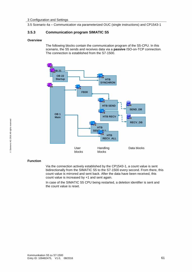
3 Configuration and Settings
3.5 Scenario 4a – Communication via parameterized OUC (single instructions) and CP1543-1
Kommunikation S5 zu S7-1500 Entry ID: 109482475, V1.0, 08/2016 61
S
iem
en
s A
G 2
91
6 A
ll ri
gh
ts r
ese
rve
d
3.5.3 Communication program SIMATIC S5
Overview
The following blocks contain the communication program of the S5-CPU. In this scenario, the S5 sends and receives data via a passive ISO-on-TCP connection.
The connection is established from the S7-1500.
OB 1
Main
OB 21
Startup
FB30
HTB
SEND_ALL
HTB
RECV_ALL
SEND_DB
RECV_DB
User
blocks
Handling
blocks
Data blocks
OB 22
Startup HTB
SYNCHRON
HTB SEND
HTB RECV
Function
Via the connection actively established by the CP1543-1, a count value is sent bidirectionally from the SIMATIC S5 to the S7-1500 every second. From there, this count value is mirrored and sent back. After the data have been received, this count value is increased by +1 and sent again.
In case of the SIMATIC S5 CPU being restarted, a deletion identifier is sent and the count value is reset.

3 Configuration and Settings
3.5 Scenario 4a – Communication via parameterized OUC (single instructions) and CP1543-1
Kommunikation S5 zu S7-1500 Entry ID: 109482475, V1.0, 08/2016 62
S
iem
en
s A
G 2
91
6 A
ll ri
gh
ts r
ese
rve
d
Description of the blocks
The following blocks contain the communication program of the S5-CPU.
Table 3-14
Block Symbol Description
OB 21 Startup_OB21 Startup OB (restart/warm start)
OB 22 Startup_OB22 Startup OB (network/cold start)
OB 1 Main User program call of FB 33 and of the HTBs SEND/RECEIVE ALL
FB 30 ID104_S7 Time-triggered call of the send and receive functions via S5 handling blocks (HTBs)
FB244 HTB_SEND Handling block SEND (-All A-NR:= 0)
FB245 HTB_RECEIVE Handling block RECEIVE (-All A-NR:= 0)
FB249 HTB_SYNCHRON Handling block SYNCHRON
DB 60 - Data area for sending
DB 50 - Data area for receiving
OB21/OB22 (STARTUP OBs)
The following functions are implemented in the startup of the SIMATIC S5-CPU:
The set interface (interface no. = 0) of the CP1430 TCP is initialized and synchronized via the handling block “HTB_Synchron” (FB 249).
An internal startup bit (M 180.5) and the initial count value are reset.
OB1 (cyclic OB)
The following functions are processed in the cyclic OB1 of the SIMATIC S5-CPU:
This example scenario 4a is started by setting an enable bit (M 130.0).
Call of the user communication block ID104_S7 (FB 30) which uses a time trigger to call the send and receive functions via S5 handling blocks (HTBs) and increments the count values in the data area.
Call of the handling blocks SEND ALL and RECEIVE ALL for data transfer to the CP1430 TCP.
FB30 (ID104_S7)
The function block FB 30 contains the time-triggered call of the send and receive functions in which a simple simulation program demonstrates the exchange of data.
An enable of the communication is initiated via the startup bit M 180.5 (OB21/22). Thus, this communication is enabled.
Every second (clock memory bit), a count value (DB60) is sent to the S7-1500 via the CP1543-1 using the ISO-on-TCP connection.
After the data have been received, this count value is checked in the S7-1500 and incremented by +1. At the next send trigger of the S7-1500, it is sent back to the SIMATIC S5. The data received by the SIMATIC S5 are transferred to DB50.
A simple error analysis regarding the connection status is done by storing the indicator words and parameter error bytes.

3 Configuration and Settings
3.5 Scenario 4a – Communication via parameterized OUC (single instructions) and CP1543-1
Kommunikation S5 zu S7-1500 Entry ID: 109482475, V1.0, 08/2016 63
S
iem
en
s A
G 2
91
6 A
ll ri
gh
ts r
ese
rve
d
HTB_SEND block: ANZW: MW60 PAFE: MB64 HTB_RECEIVE block: ANZW: MW50 PAFE: MB54
3.5.4 Connection configuration in the S7-1500 CPU
Prerequisite
All network-side settings of the S7-1500 CPU and of the CP1543-1 used in TIA Portal are structured identically for all scenarios.
For the corresponding configuration steps, proceed as described in chapter “3.1.4– Connection configuration in the SIMATIC S7-1500” steps 1 and 2 of scenario 1 and complete the configuration following the steps described in the next section.
Configuration
In this scenario 4a, the connection is parameterized via a dialog in TIA Portal. The required connection parameter are pre-assigned and set up via a connection table in the S7-1500 CPU.
3. In the “Device configuration” (1) of the “PLC_Sz4..”, open the “Network view” (2). In the “Connections” tab (3), select your CPU and use the “Insert” menu
item or right-click to add a new connection.
4. Now, under “Unspecified” (1), enter “104” as “Local ID” (2). Tick the “Establish active connection” option (3) to enable this connection property. Under “Type” (4), select “ISO-on-TCP connection” and confirm your settings by clicking the “Close” button.
1
2 3

3 Configuration and Settings
3.5 Scenario 4a – Communication via parameterized OUC (single instructions) and CP1543-1
Kommunikation S5 zu S7-1500 Entry ID: 109482475, V1.0, 08/2016 64
S
iem
en
s A
G 2
91
6 A
ll ri
gh
ts r
ese
rve
d
5. In the “Properties” of the ISO-on-TCP connection, go to “General” (1) to assign the name of the connection. In this example, “ISO-on-TCP_CP1543-S5” is set (2). Make sure that the CP1543-1 Ethernet interface E1 of the CP1543-1 is set for the “Interface” parameter (3). Now, in the “Partner” section (4), enter the IP address (IP: 140.140.111.104) of the SIMATIC S5 CP1430 TCP (5).
6. Under “Address details”, enter the local (1) and “remote” (2) TSAPs for the ISO-on-TCP connection. The TSAPs have been taken from the configuration of the CP1430 TCP (see chapter 3.1.5) as follows.
local TSAP : “CP1543-0” remote TSAP : “CP1543-0”
1
2 3
4
1 2
3 4

3 Configuration and Settings
3.5 Scenario 4a – Communication via parameterized OUC (single instructions) and CP1543-1
Kommunikation S5 zu S7-1500 Entry ID: 109482475, V1.0, 08/2016 65
S
iem
en
s A
G 2
91
6 A
ll ri
gh
ts r
ese
rve
d
After having completed the settings for this ISO-on-TCP connection, the project has to be compiled again. To do this, select the S7 station, store it and thus compile this S7 station.
3.5.5 Connection configuration in the CP1430 TCP (SIMATIC S5)
Introduction
The following settings are used to establish a “passive” ISO-on-TCP DUPLEX
connection to the CP1543-1.
Note The CP1430 TCP configuration file “TCP1430A.TCP” already contains the complete configurations for all 6 example scenarios. Thus, after loading the CP1430 file, all other connections are also available “offline” in the CP1430 TCP.
Configuration
The “passive” connection for scenario 2a in the CP1430 TCP is created using the “SINEC NCM COM 1430 TCP” configuration tool.
Note The "SINEC NCM COM 1430" configuration tool is an additional software that is integrated in STEP 5 to configure the CP1430 TCP. This software is not included in the standard STEP 5 package and must be installed additionally.
The connection configuration is largely identical to chapter 3.1.5 Connection configuration in the CP1430 TCP (SIMATIC S5)”. Follow the steps 1 to 8 described in that chapter and complete the configuration following the steps described below.
9. For this example (scenario 4a), two ISO-on-TCP connections (transport connections RFC 1006) are required. To set up the “passive” connection, the job “1 of 2” must be parameterized as a RECEIVE type. In the subsequent mask of the job, the TSAP “CPU1543-0” is entered. The job “2 of 2” must be set up as a SEND job type.

3 Configuration and Settings
3.5 Scenario 4a – Communication via parameterized OUC (single instructions) and CP1543-1
Kommunikation S5 zu S7-1500 Entry ID: 109482475, V1.0, 08/2016 66
S
iem
en
s A
G 2
91
6 A
ll ri
gh
ts r
ese
rve
d
Enter
– for the passive ISO-on-TCP connection under (1) the job number ANR “3”,
– under (2) the job type: “RECEIVE”,
– under “Transport addresses” (3) the local TSAP “CP1543-0” and under (4) the remote TSAP “CP1543-0”,
– under “Number of jobs per TSAP” (5) “1 of 2”.
7. Now, create job 2 of 2 with “+1” (F1). Enter
– under (1) the job number ANR with “103”,
– under (2) the job type: “SEND”.
– Click on “OK” (F7) to confirm the settings.
1
2
3 4
5
1 2

3 Configuration and Settings
3.6 Scenario 4b – Communication via programmed OUC (single instructions) and CP1543-1
Kommunikation S5 zu S7-1500 Entry ID: 109482475, V1.0, 08/2016 67
S
iem
en
s A
G 2
91
6 A
ll ri
gh
ts r
ese
rve
d
3.6 Scenario 4b – Communication via programmed OUC (single instructions) and CP1543-1
3.6.1 Mode of operation
Overview
In this scenario, the SIMATIC S5 actively establishes an ISO-on-TCP connection to the S7-1500 CPU via the CP1430 TCP using the CP1543-1.
On the S7-1500 CPU end, the programmed connection is set up passively via the OUC block TCON by the user program and is available for establishing the connection of the partner. The data then are sent and received via the blocks TSEND and TRCV.
For this connection, the SIMATIC S5 uses the standard handling blocks SYNCHRON/SEND/RECEIVE. In the CP1430 TCP, the ISO-on-TCP connection in the SIMATIC S5 is configured as an “active” duplex connection.
Note This scenario 4b is almost identical to scenario 2b. For this reason, please refer to the corresponding sections of scenario 2 (chapter 3.3) in case of identical chapters.

3 Configuration and Settings
3.6 Scenario 4b – Communication via programmed OUC (single instructions) and CP1543-1
Kommunikation S5 zu S7-1500 Entry ID: 109482475, V1.0, 08/2016 68
S
iem
en
s A
G 2
91
6 A
ll ri
gh
ts r
ese
rve
d
Sequence of the parameterized OUC communication between S7 and S5 via single
instructions and CP1543-1
The figure below schematically shows the connection established and the data flow between SIMATIC S5 and SIMATIC S7-1500 using the programmed SEND and RECEIVE mechanism via ISO-on-TCP.
Flow chart
OB1
SIMATIC S5 CPU SIMATIC S7-1500 CPU
SEND job trigger
CP1430
TCP
SEND
RECEIVE
Data
Data
Value 1
Value 2
…
…
…
Value 1
Value 2
…
…
…
FB40
HTB
SEND
HTB
RECEIVE
RECEIVE
ALL
SEND
ALL
CP1543-1
Conection
configuration Connection
1
2
3
Connect
conn.
passive
ID 4
TSAP 1
TCON
Conn.establ./disconn.
CR
CC
HTB
SYNCRON
Acknowledgment
Acknowledgment
A_NR
TSAP 1SEND/RCV
…
RECEIVE ready to receive
CONNECT
4
5
Value 1
Value 2
…
Value 1
Value 2
…
TRCV
TSEND
SEND
RECEIVE
TDISCON
Table 3-15
No. Process
1 Startup of the SIMATIC S5 and synchronization with the CP1430 TCP.
2 The cyclic processing of the HTB RECEIVE block in the S5-CPU ensures readiness to receive between the CPU and the CP1430 TCP. The data are transferred from the CP1430 TCP to the data block of the SIMATIC S5-CPU via the RECEIVE ALL handling block.
3 The SIMATIC S5 transfers the SEND job to the CP1430 TCP via HTB SEND. The data are transferred from the SIMATIC S5-CPU (data block) to the CP1430 TCP via the SEND ALL handling block.
4 The received data are transferred to the S7-1500 CPU via the cyclic processing of the OUC block TRCV. If the data have been received successfully, this is shown by a positive acknowledgment and signaled at block parameter NDR. Otherwise, a negative acknowledgment will be sent for the job.
5 A SEND job is sent from the S7-1500 CPU to the SIMATIC S5 via the OUC block TSEND. In this scenario, the block sends a job to the SIMATIC S5 CP1430 TCP every second. In the S5-CPU, the data are transferred via the standard HTBs RECEIVE and RECEIVE ALL.
3.6.2 Communication program in the SIMATIC S7-1500
Overview
The following blocks contain the communication program in the S7-1500 CPU.

3 Configuration and Settings
3.6 Scenario 4b – Communication via programmed OUC (single instructions) and CP1543-1
Kommunikation S5 zu S7-1500 Entry ID: 109482475, V1.0, 08/2016 69
S
iem
en
s A
G 2
91
6 A
ll ri
gh
ts r
ese
rve
d
RecvDataSendData
OB 1Main
OB 100Startup
FB 5 ConnManager
ParamID4
User
blocks
TCON
TSEND
TDISCON
TRCV
OUC system
blocks
Function
A programmed OUC communication is set up passively by calling the OUC communication block TCON. In this case, the connection is established actively from the SIMATIC S5. As soon as the connection is established, the data are exchanged via the OUC communication blocks TSEND and TRCV.
To detect the ongoing data communication in the S7-1500, a count value is received by the SIMATIC S5, mirrored and sent back. For visualization, the received count value is transferred to the output area AB0.
Description of the blocks
Table 3-16
Block Symbol Description
OB 100 Startup Startup OB
OB 1 Main Cyclic OB
FB 5 ConnManagerProgID4 Management of connection ID 4
DB 29 InstConnManagerProgID4 Instance DB of FB 4 (+send/receive data area)
DB 25 ConnectParamID4 Connect parameter ID4
DB 24 InstTCONID4 Instance DB TCON ID 4
DB 28 InstTDISCONID4 Instance DB TDISCON ID 4
DB 26 InstTSENDID4 Instance DB TSEND ID 4
DB 27 InstTRCVID4 Instance DB TRCV ID 4
OB 100 (startup OB)

3 Configuration and Settings
3.6 Scenario 4b – Communication via programmed OUC (single instructions) and CP1543-1
Kommunikation S5 zu S7-1500 Entry ID: 109482475, V1.0, 08/2016 70
S
iem
en
s A
G 2
91
6 A
ll ri
gh
ts r
ese
rve
d
After having restarted the S7-1500 CPU, the connect enable bit “statConnID4” is reset. It has the effect that a passively programmed connection is set up in the cyclic program.
OB 1 (cyclic OB)
Via the enable input “E 0.2” (abortReq), the OB1 calls FB 5 which manages the OUC communication.
FB 5 (TSEND/TRCV management)
In FB 5, it is checked via the connect enable bit whether the CPU is restarted. If this is the case, the passive ISO-on-TCP connection is set up via the OUC block TCON.
If the connection has been established successfully, the data are received by the SIMATIC S5 via the cyclically called OUC communication block TRCV. To visualize the ongoing communication, a count value is copied to an output area (AB 0) of the S7-1500.
The count value received by the SIMATIC S5 is located in the instance data block of FB5 in the static tag “statRcvData” and is copied to the send area of the instance data block “statSendData” for sending.
Via a send enable “E0.1”, these data are mirrored and sent back to the SIMATIC S5 every of 500 ms.
In addition, the received data are checked.
- The data are cyclically checked for a deletion identifier (“A1A1”) being available. In case of a match, the count value is reset.
- The ongoing communication of the OUC communication is visualized via the output area of the S7-1500.

3 Configuration and Settings
3.6 Scenario 4b – Communication via programmed OUC (single instructions) and CP1543-1
Kommunikation S5 zu S7-1500 Entry ID: 109482475, V1.0, 08/2016 71
S
iem
en
s A
G 2
91
6 A
ll ri
gh
ts r
ese
rve
d
3.6.3 Communication program SIMATIC S5
Overview
The following blocks contain the communication program of the S5-CPU. In this scenario, the S5 sends and receives data via an active ISO-on-TCP connection.
The connection is established from the SIMATIC S5.
OB 1
Main
OB 21
Startup
FB31
HTB
SEND_ALL
HTB
RECV_ALL
SEND_DB
RECV_DB
User
blocks
Handling
blocks
Data blocks
OB 22
Startup HTB
SYNCHRON
HTB SEND
HTB RECV
Function
Via the connection actively established by the SIMATIC S5, data are sent bidirectionally with a count value to the S7-1500 every second. From there, this count value is mirrored and sent back. After the data have been received, this count value is increased by +1 and sent again.
In case of the SIMATIC S5 CPU being restarted, a deletion identifier is sent to the S7-1500 and the count value is reset.
Description of the blocks
The following blocks contain the communication program of the S5-CPU.
Table 3-17
Block Symbol Description
OB 21 Startup_OB21 Startup OB (restart/warm start)
OB 22 Startup_OB22 Startup OB (network/cold start)
OB 1 Main User program call of FB 33 and of the HTBs

3 Configuration and Settings
3.6 Scenario 4b – Communication via programmed OUC (single instructions) and CP1543-1
Kommunikation S5 zu S7-1500 Entry ID: 109482475, V1.0, 08/2016 72
S
iem
en
s A
G 2
91
6 A
ll ri
gh
ts r
ese
rve
d
Block Symbol Description
SEND/RECEIVE ALL
FB 31 ID4_S7 Time-triggered call of the send and receive functions via S5 handling blocks (HTBs). Increase of count value in the data
FB244 HTB_SEND Handling block SEND (-All A-NR:= 0)
FB245 HTB_RECEIVE Handling block RECEIVE (-All A-NR:= 0)
FB249 HTB_SYNCHRON Handling block SYNCHRON
DB 61 - Data area for sending
DB 51 - Data area for receiving
OB21/OB22 (STARTUP OBs)
The following functions are implemented in the startup of the SIMATIC S5-CPU:
The set interface (interface no. = 0) of the CP1430 TCP is initialized and synchronized via the handling block “HTB_Synchron” (FB 249).
An internal startup bit (M 190.5) resets the initial count value.
OB1 (cyclic OB)
The following functions are processed in the cyclic OB1 of the SIMATIC S5-CPU:
This example scenario 4b is started via the enable bit (M 130.1).
Call of the user communication block ID4_S7 (FB 31) which calls the send and receive functions via S5 handling blocks (HTBs) and increments the count values in the data area.
Call of the handling blocks SEND ALL and RECEIVE ALL for data transfer to the CP1430 TCP.
FB31 (ID4_S7CP)
The function block FB 31 contains the time-triggered call of the send and receive functions in which a simple simulation program demonstrates the exchange of data.
An enable of the communication is initiated via the startup bit M 190.5 (OB21/22).
After the data have been received, this count value is checked in the S7-1500, incremented by +1 and sent back to the SIMATIC S5 at the next send trigger of the S7-1500. The data received by the SIMATIC S5 are transferred to DB101.
A simple error analysis regarding the connection status is done by storing the indicator words and parameter error bytes. HTB_SEND block: ANZW: MW65 PAFE: MB69 HTB_RECEIVE block: ANZW: MW55 PAFE: MB59

3 Configuration and Settings
3.6 Scenario 4b – Communication via programmed OUC (single instructions) and CP1543-1
Kommunikation S5 zu S7-1500 Entry ID: 109482475, V1.0, 08/2016 73
S
iem
en
s A
G 2
91
6 A
ll ri
gh
ts r
ese
rve
d
3.6.4 Connection configuration in the S7-1500 CPU
Prerequisite
All network-side settings of the S7-1500 CPU and of the CP1543-1 used in TIA Portal are structured identically for all scenarios.
For the corresponding configuration steps, proceed as described in chapter “3.1.4– Connection configuration in the SIMATIC S7-1500” steps 1 and 2 of scenario 1 and complete the configuration following the steps described in the next section.
Configuration
For configuring a “parameterized” ISO-on-TCP connection via a S7-1500 CPU, the following settings in TIA Portal are required. Make corresponding hardware and network settings as described in example scenario 1.
Create a data block and add a tag of data type “TCON_IP_RFC”. The default settings for scenario 4b have to be parameterized as follows.
– Enter die module address of the CP1543-1 (in this case: 264) for the “InterfaceId” tag (1).
– Enter the connection number (in this case: 4) for the “ID” tag (2).
– The value “16#0C” of the “ConnectionType” tag (3) defines the connection
type “ISO-on-TCP”.
– Enter the value “false” for the “ActiveEstablished” tag (4) to define the
passive connection establishment of the S7-1500 station.
– Enter the IP address of the partner (in this case: of the CP1430 TCP) in the “RemoteAddress” field (5).
– Enter the remote TSAP (in this case: 43 50 31 35 34 33 2D 31 (hex) “CP1543-1” (ASC)) and the local TSAP (in this case: 43 50 31 35 34 33 2D 31 (hex) “CP1543-1” (ASC)) in the fields “RemoteTSelector” (6) and “LocalTSelector” (7), respectively.
Figure 3-2
1
2 3
4 5

3 Configuration and Settings
3.6 Scenario 4b – Communication via programmed OUC (single instructions) and CP1543-1
Kommunikation S5 zu S7-1500 Entry ID: 109482475, V1.0, 08/2016 74
S
iem
en
s A
G 2
91
6 A
ll ri
gh
ts r
ese
rve
d
3.6.5 Connection configuration in the CP1430 TCP (SIMATIC S5)
Introduction
The following settings are used to establish an “active” ISO-on-TCP DUPLEX
connection to the CP1543-1.
Note The CP1430 TCP configuration file “TCP1430A.TCP” already contains the complete configurations for all 6 example scenarios. Thus, after loading the CP1430 file, all other connections are also available “offline” in the CP1430 TCP.
Configuration
The “active” connection for scenario 4b in the CP1430 TCP is created using the “SINEC NCM COM 1430 TCP” configuration tool.
Note The "SINEC NCM COM 1430" configuration tool is an additional software that is integrated in STEP 5 to configure the CP1430 TCP. This software is not included in the standard STEP 5 package and must be installed additionally.
The connection configuration is largely identical to chapter 3.1.5 Connection configuration in the CP1430 TCP (SIMATIC S5)”. Follow the steps 1 to 8 described in that chapter and complete the configuration following the steps described below.
9. For this example (scenario 4b), two ISO-on-TCP connections (transport connections RFC 1006) are required. To set up the “active” connection, the job “1 of 2” must be parameterized as a SEND type. In the subsequent mask of the job, the TSAP “CP1543-1”
has to be entered. The job “2 of 2” must be set up as a RECEIVE job type.
6
7

3 Configuration and Settings
3.6 Scenario 4b – Communication via programmed OUC (single instructions) and CP1543-1
Kommunikation S5 zu S7-1500 Entry ID: 109482475, V1.0, 08/2016 75
S
iem
en
s A
G 2
91
6 A
ll ri
gh
ts r
ese
rve
d
Enter
– for the passive ISO-on-TCP connection under (1) the job number ANR “102”,
– under (2) the job type: “SEND”,
– under “Transport addresses” (3) the local TSAP “CP1543-1” and under (4) the remote TSAP “CP1543-1”,
– under “Number of jobs per TSAP” (5) “1 of 2”.
– under the “Active/passive” parameter (6) the connection establishment “A”
(active).
8. Now, create job 2 of 2 with “+1” (F1). Enter
– under (1) the job number ANR with “2”,
– under (2) the job type: “RECEIVE”.
– Click on “OK” (F7) to confirm the settings.
1
2
3 4
5
1
2

3 Configuration and Settings
3.7 Scenario 5 – Communication via programmed OUC (compact instructions) and internal CPU interface
Kommunikation S5 zu S7-1500 Entry ID: 109482475, V1.0, 08/2016 76
S
iem
en
s A
G 2
91
6 A
ll ri
gh
ts r
ese
rve
d
3.7 Scenario 5 – Communication via programmed OUC (compact instructions) and internal CPU interface
3.7.1 Mode of operation
Overview
This scenario presents a variant of the OUC communication, in which the S7-1500 station uses the compact OUC block “TSEND_C” to send data to the SIMATIC S5. In this case, the receipt of the data is implemented via the standard OUC block TRCV.
Via the CP1430 TCP, the S7-1500 station actively establishes an ISO-on-TCP
connection to the SIMATIC S5 using its internal CPU interface.
For this connection, the SIMATIC S5 uses the standard handling blocks SYNCHRON/SEND/RECEIVE. In the CP1430 TCP, the ISO-on-TCP connection in the SIMATIC S5 is configured as a “passive” duplex connection.

3 Configuration and Settings
3.7 Scenario 5 – Communication via programmed OUC (compact instructions) and internal CPU interface
Kommunikation S5 zu S7-1500 Entry ID: 109482475, V1.0, 08/2016 77
S
iem
en
s A
G 2
91
6 A
ll ri
gh
ts r
ese
rve
d
Sequence of the programmed OUC communication between S7 and S5 via compact
instructions
The figure below schematically shows the connection established and the data flow between SIMATIC S5 and SIMATIC S7-1500 using the programmed SEND and RECEIVE mechanism via ISO-on-TCP.
Flow chart
OB1
SIMATIC S5 CPU SIMATIC S7-1500 CPU
SEND job trigger
CP1430 TCP
SEND
RECEIVE
Data
Acknowledgment
Value 1
Value 2
…
Value 1
Value 2
…
Value 1
Value 2
…
…
…
Value 1
Value 2
…
…
…
FB40
HTB
SEND
HTB
RECEIVE
RECEIVE
ALL
SEND
ALL
PNIO-SS
Connectionconfiguration Connection
1
2
3
TRCV
Conn.establ.
CR
CC
HTB
SYNCRON
Acknowledgment
A_NR
TSAP 1SEND/RCV
…
ID 6
TSAP 1SEND/RCV
…
TSEND_C RECEIVE ready to receive
structure ofconnection
RECEIVE
SEND
4
5
Table 3-18
No. Process
1 Startup of the SIMATIC S5 and synchronization with the CP1430 TCP.
2 The job trigger of the OUC block TSEND_C is performed every second. With the first triggering, the block establishes an active connection. If the connection has been established successfully, the data are sent to the SIMATIC S5. The connection remains established.
3 The SIMATIC S5 transfers the SEND job to the CP1430 TCP via HTB SEND. The data are transferred from the SIMATIC S5-CPU (data block) to the CP1430 TCP via the SEND ALL handling block.
4 The received data are transferred to the S7-1500 CPU via the cyclic processing of the OUC block TRCV. If the data have been received successfully, this is shown by a positive acknowledgment and signaled at block parameter NDR. Otherwise, a negative acknowledgment will be sent for the job.
5 The cyclic processing of the HTB RECEIVE block in the S5-CPU ensures readiness to receive between the CPU and the CP1430 TCP. The data are transferred from the CP1430 TCP to the data block of the SIMATIC S5-CPU via the RECEIVE ALL handling block.

3 Configuration and Settings
3.7 Scenario 5 – Communication via programmed OUC (compact instructions) and internal CPU interface
Kommunikation S5 zu S7-1500 Entry ID: 109482475, V1.0, 08/2016 78
S
iem
en
s A
G 2
91
6 A
ll ri
gh
ts r
ese
rve
d
3.7.2 Communication program in the SIMATIC S7-1500
The following blocks contain the communication program in the S7-1500 CPU.
Overview
OB 1
Main
OB 100
Startup
RecvData
SendData
FB 6
ConnManager
ParamID6
User
blocks
TSEND_C
TDISCON
TRCV
OUC system
blocks
Function
The OUC block TSEND_C is used to actively establish a connection via the integrated PNIO interface of the CPU by calling the FB 6 (ConnManagerParamID6). As soon as the connection is established, the data are exchanged via the communication blocks TSEND_C and TRCV.
Via the connection, data are sent bidirectionally with a count value from the SIMATIC S5 to the S7-1500 every second. From there, this count value is mirrored and sent back. After the data have been received, this count value is increased by +1 and sent again.
Note The mixed variant of the OUC blocks TSEND_C (compact instruction) and TRCV (single instruction) used in this example scenario is recommended, if only one connection ID shall be used for sending and receiving the data. Further details and information concerning this mixed operation are given in the following entry (109479564).
Block Symbol Description
OB 100 Startup Startup OB
OB 1 Main Cyclic OB

3 Configuration and Settings
3.7 Scenario 5 – Communication via programmed OUC (compact instructions) and internal CPU interface
Kommunikation S5 zu S7-1500 Entry ID: 109482475, V1.0, 08/2016 79
S
iem
en
s A
G 2
91
6 A
ll ri
gh
ts r
ese
rve
d
Block Symbol Description
FB 6 ConnManagerProgID6 Management TSEND_C ID 6
DB 35 InstConnManagerProgID6
DB 25 ConnectParamID6 Connect parameter ID 6
DB 4 InstTSEND_C_ID6 Instance DB TSEND_C ID 6
DB 3 InstTRCV_ID6 Instance DB TRCV ID 6
DB 100 ParaDbID6_TSEND_C Parameter DB TSEND_C
DB 200 ParaDbID6_TRCV Parameter DB TRCV
DB 110 DataTSEND_C Send data area
DB 210 DataTRCV Receive data area

3 Configuration and Settings
3.7 Scenario 5 – Communication via programmed OUC (compact instructions) and internal CPU interface
Kommunikation S5 zu S7-1500 Entry ID: 109482475, V1.0, 08/2016 80
S
iem
en
s A
G 2
91
6 A
ll ri
gh
ts r
ese
rve
d
3.7.3 Communication program SIMATIC S5
Overview
The following blocks contain the communication program of the S5-CPU. In this scenario, the S5 sends and receives data via a passive ISO-on-TCP connection.
The connection is established from the S7-1500 CPU.
OB 1
Main
OB 21
Startup
FB35
HTB
SEND_ALL
HTB
RECV_ALL
SEND_DB
RECV_DB
User
blocks
Handling
blocks
Data blocks
OB 22
Startup HTB
SYNCHRON
HTB SEND
HTB RECV
Function
Via the connection actively established by the S7-1500 CPU, data are sent bidirectionally with a count value from the SIMATIC S5 to the S7-1500 every second. From there, this count value is mirrored and sent back. After the data have been received, this count value is increased by +1 and sent again.
In case of the SIMATIC S5 CPU being restarted, a deletion identifier is sent and the count value is reset.
Description of the blocks
The following blocks contain the communication program of the S5-CPU.
Table 3-19
Block Symbol Description
OB 21 Startup_OB21 Startup OB (restart/warm start)
OB 22 Startup_OB22 Startup OB (network/cold start)
OB 1 Main User program call of FB 33 and of the HTBs SEND/RECEIVE ALL
FB 35 ID6_S7 Time-triggered call of the send and receive

3 Configuration and Settings
3.7 Scenario 5 – Communication via programmed OUC (compact instructions) and internal CPU interface
Kommunikation S5 zu S7-1500 Entry ID: 109482475, V1.0, 08/2016 81
S
iem
en
s A
G 2
91
6 A
ll ri
gh
ts r
ese
rve
d
Block Symbol Description
functions via S5 handling blocks (HTBs). Increase of count value in the data
FB244 HTB_SEND Handling block SEND (-All A-NR:= 0)
FB245 HTB_RECEIVE Handling block RECEIVE (-All A-NR:= 0)
FB249 HTB_SYNCHRON Handling block SYNCHRON
DB 110 - Data area for sending
DB 111 - Data area for receiving
OB21/OB22 (STARTUP OBs)
The following functions are implemented in the startup of the SIMATIC S5-CPU:
The set interface (interface no. = 0) of the CP1430 TCP is initialized and synchronized via the handling block “HTB_Synchron” (FB 249).
An internal startup bit (M 160.5) resets the initial count value.
OB1 (cyclic OB)
The following functions are processed in the cyclic OB1 of the SIMATIC S5-CPU:
This example scenario 5 is started via the enable bit (M 130.6).
Call of the user communication block ID6_S7 (FB 35) which calls the send and receive functions via S5 handling blocks (HTBs) and increments the count values in the data area.
Call of the handling blocks SEND ALL and RECEIVE ALL for data transfer to the CP1430 TCP.
FB35 (ID6_S7)
The function block FB 35 contains the time-triggered call of the send and receive functions in which a simple simulation program demonstrates the exchange of data.
Communication is initiated via the startup bit M 160.5 (OB21/22) and the enable bit (M 130.6).
Every second (clock memory bit), a count value (DB110) is sent to the S7-1500 CPU via the ISO-on-TCP connection.
After the data have been received, this count value is checked in the S7-1500, incremented by +1 and sent back to the SIMATIC S5 at the next send trigger of the S7-1500. The data received by the SIMATIC S5 are transferred to DB101.
A simple error analysis regarding the connection status is done by storing the indicator words and parameter error bytes. HTB_SEND block: ANZW: MW100 PAFE: MB104 HTB_RECEIVE block: ANZW: MW115 PAFE: MB119

3 Configuration and Settings
3.7 Scenario 5 – Communication via programmed OUC (compact instructions) and internal CPU interface
Kommunikation S5 zu S7-1500 Entry ID: 109482475, V1.0, 08/2016 82
S
iem
en
s A
G 2
91
6 A
ll ri
gh
ts r
ese
rve
d
3.7.4 Connection configuration in the S7-1500 CPU
Prerequisites
All network-side settings of the S7-1500 CPU and of the CP1543-1 used in TIA Portal are structured identically for all scenarios.
For the corresponding configuration steps, proceed as described in chapter “3.1.4– Connection configuration in the SIMATIC S7-1500” steps 1 and 2 of scenario 1 and complete the configuration following the steps described in the next section.
Configuration
In this scenario 5, all required connection parameters of an ISO-on-TCP connection are pre-assigned and set up via the user program.
The CONNECT parameter of the OUC block TSEND_C is used to configure the predefined structure (TCON_IP_RFC) of an ISO-on-TCP connection as follows.
3. Create a data block and add a tag of data type “TCON_IP_RFC”. The default settings for scenario 3 have to be parameterized as follows.
– Enter die module address of the S7-1500 CPU (in this case: 64) for the “InterfaceId” tag (1).
– Enter the connection number (in this case: 6) for the “ID” tag (2).
– The value “16#0C” of the “ConnectionType” tag (3) defines the connection
type “ISO-on-TCP”.
– Enter the value “true” for the “ActiveEstablished” tag (4) to define the active
connection establishment of the S7-1500 station.
– Enter the IP address of the partner (in this case: of the CP1430 TCP) in the “RemoteAddress” field (5).
– Enter the remote TSAP (in this case: 43 50 55 5F 31 35 30 63 (hex) “CPU_150c” (ASC)) and the local TSAP (in this case: 43 50 55 5F 31 35 30 63 (hex) “CPU_150c” (ASC)) in the fields “RemoteTSelector” (6) and “LocalTSelector” (7), respectively.
1
2
4
3
5
6

3 Configuration and Settings
3.7 Scenario 5 – Communication via programmed OUC (compact instructions) and internal CPU interface
Kommunikation S5 zu S7-1500 Entry ID: 109482475, V1.0, 08/2016 83
S
iem
en
s A
G 2
91
6 A
ll ri
gh
ts r
ese
rve
d
3.7.5 Connection configuration in the CP1430 TCP (SIMATIC S5)
Introduction
Make the following settings to establish a “passive” ISO-on-TCP DUPLEX
connection to a S7-1500 CPU with an integrated PROFINET interface.
Note The CP1430 TCP configuration file “TCP1430A.TCP” already contains the complete configurations for all 7 example scenarios. Thus, after loading the CP1430 file, all other connections are also available “offline” in the CP1430 TCP.
Configuration
The “passive” connection for scenario 5 in the CP1430 TCP is created using the “SINEC NCM COM 1430 TCP” configuration tool.
Note The "SINEC NCM COM 1430" configuration tool is an additional software that is integrated in STEP 5 to configure the CP1430 TCP. This software is not included in the standard STEP 5 package and must be installed additionally.
The connection configuration is largely identical to chapter 3.1.5 Connection configuration in the CP1430 TCP (SIMATIC S5)”. Follow the steps 1 to 8 described in that chapter and complete the configuration following the steps described below.
9. For this example, two ISO-on-TCP connections (transport connections RFC 1006) are required. To set up the “passive” connection, the job “1 of 2” must be parameterized as a RECEIVE type. In the subsequent mask of the job, the TSAP “CPU_150c” has to be entered. The job “2 of 2” must be set up as a SEND job type.
Enter
– for the passive ISO-on-TCP connection under (1) the job number ANR “53”,
– under (2) the job type: “RECEIVE”,
– under “Transport addresses” (3) the local TSAP “CPU_150c” and under (4) the remote TSAP “CPU_150c”,
– under “Number of jobs per TSAP” (5) “1 of 2”.
7
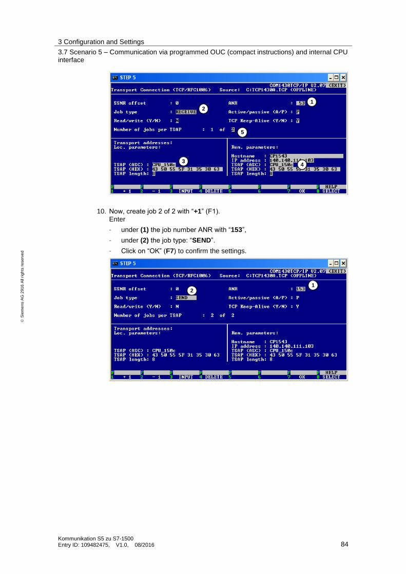
3 Configuration and Settings
3.7 Scenario 5 – Communication via programmed OUC (compact instructions) and internal CPU interface
Kommunikation S5 zu S7-1500 Entry ID: 109482475, V1.0, 08/2016 84
S
iem
en
s A
G 2
91
6 A
ll ri
gh
ts r
ese
rve
d
10. Now, create job 2 of 2 with “+1” (F1). Enter
– under (1) the job number ANR with “153”,
– under (2) the job type: “SEND”.
– Click on “OK” (F7) to confirm the settings.
1
2
3 4
5
1 2
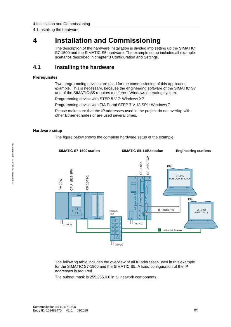
4 Installation and Commissioning
4.1 Installing the hardware
Kommunikation S5 zu S7-1500 Entry ID: 109482475, V1.0, 08/2016 85
S
iem
en
s A
G 2
91
6 A
ll ri
gh
ts r
ese
rve
d
4 Installation and Commissioning The description of the hardware installation is divided into setting up the SIMATIC S7-1500 and the SIMATIC S5 hardware. The example setup includes all example scenarios described in chapter 3 Configuration and Settings.
4.1 Installing the hardware
Prerequisites
Two programming devices are used for the commissioning of this application example. This is necessary, because the engineering software of the SIMATIC S7 and of the SIMATIC S5 requires a different Windows operating system.
Programming device with STEP 5 V 7: Windows XP
Programming device with TIA Portal STEP 7 V 13 SP1: Windows 7
Please make sure that the IP addresses used in the project do not overlap with other Ethernet nodes or are used several times.
Hardware setup
The figure below shows the complete hardware setup of the example.
SIMATIC S5-115U stationC
P 1
43
0 T
CP
SIMATIC S7-1500 station
CP
U 9
44
CP
15
43
-1
CP
U 1
51
6-3
PN
Industrial Ethernet
TIA Portal
STEP 7 V 13RS232/TTY
PG
Engineering stations
OUC: Open User Communication
PM
70
W
Scalance X208
230 V AC 230 V AC
STEP 5
NCM COM 1430TCP
PG
24 V DC
The following table includes the overview of all IP addresses used in this example for the SIMATIC S7-1500 and the SIMATIC S5. A fixed configuration of the IP addresses is required.
The subnet mask is 255.255.0.0 in all network components.

4 Installation and Commissioning
4.1 Installing the hardware
Kommunikation S5 zu S7-1500 Entry ID: 109482475, V1.0, 08/2016 86
S
iem
en
s A
G 2
91
6 A
ll ri
gh
ts r
ese
rve
d
Table 4-1
Device IP address Designation
SIMATIC S7
CPU1516 -3PN 140.140.111.102 (port X1) SIMATIC S7-1500 CPU
CP1543-1 140.140.111.103 (port X1) SIMATIC S7 CP1543-1
SIMATIC S5
CP1430 TCP 140.140.111.104 SIMATIC S5 CP1430 TCP
PG/PC
PG/PC (WinXP/STEP5) 140.140.111.100 Programming device with STEP5 and NCM COM 1430TCP
PG/PC (TIA Portal V 13 SP1)
140.140.111.101 Programming device with TIA Portal V 13 SP1
Note In general, the installation guidelines of all components have to be observed. Please observe the installation and connection guidelines from the corresponding manuals of the components used.
4.1.1 Installing the hardware for the S7-1500 station
For setting up the hardware, please proceed according to the following table:
No. Action Remark
1. PC/PG Connect the PC/PG to the SCALANCE switch via a standard Ethernet cable (RJ 45).
2. Install the S7-1500 power supply
Connect the power module to the power grid (220 / 230 V AC).
The SIMATIC S7 PM module supplies all modules required for the S7-1500 station.
3. S7 CPU1516-3 PN Expand the S7-1500 CPU 1516 with the PM module via backplane bus connectors.
Connect the Ethernet port X1 (RJ 45) to a port of the SCALANCE switch.
4. CPU 1543-1 Connect the CP1543-1 to the CPU 1516-3PN via a backplane bus connector.
Connect the Ethernet port X1 (RJ 45) of the CP to the SCALANCE switch via a standard Ethernet cable (RJ 45).
5. I/O modules Connect the I/O modules to the CP1543-1 via backplane bus connectors.
Use an external 24V DC power supply to supply the I/O modules with power.

4 Installation and Commissioning
4.2 Installing the application software
Kommunikation S5 zu S7-1500 Entry ID: 109482475, V1.0, 08/2016 87
S
iem
en
s A
G 2
91
6 A
ll ri
gh
ts r
ese
rve
d
4.1.2 Installing the hardware for the SIMATIC S5 station
For setting up the hardware, please proceed according to the following table:
Table 4-2
No. Action Remark
1. PC/PG Connect the PC/PG with STEP 5 being installed to the SIMATIC S5 (CPU 944 and/or CP1430TCP) via the serial interface and the PG-AG cable.
2. Power supply PS 7A/15A Plug the power supply PS 7A/15A into the backplane bus UR 1 of the SIMATIC S5 and connect it to the power grid (220 / 230 V AC).
3. S5-CPU944 Plug RAM modules into the CPU 944 and the CPU into the S5 backplane bus UR1 at the CPU slot.
4. S5 CP1430 TCP Plug the CP1430 TCP into the S5 backplane bus UR 1 via an adaptation capsule. Plug a RAM module into the CP1430 TCP.
Connect the 15-pin Ethernet connection of the CP1430 TCP to the SCALANCE switch via a TP cord cable (15-pin/RJ45).
4.2 Installing the application software
Prerequisites
SIMATIC S5 station:
Programming device with
STEP 5 V7.2
SINEC NCM COM 1430 TCP V 2.07
Operating system: Windows XP SP3
SIMATIC S7 station:
Programming device with TIA Portal V 13 SP1
Operating system: Windows 7
Note The required SIMATIC S5 software can only be installed with the Windows XP operating system.
The TIA Portal STEP 7 V 13 SP1 configuration software can only be installed with Windows 7 or higher.
4.2.1 S7-1500 application software
Overview of example scenarios in S7-1500 stations
The example project in the S7-1500 is structured in such a way that an own S7 station is available for all example scenarios described in chapter 3 – Configuration

4 Installation and Commissioning
4.3 Commissioning
Kommunikation S5 zu S7-1500 Entry ID: 109482475, V1.0, 08/2016 88
S
iem
en
s A
G 2
91
6 A
ll ri
gh
ts r
ese
rve
d
and Settings demonstrating only this communication variant in connection with the CP1430 TCP.
Table 4-3
Scen. Station name Description
1 PLC_Sz1_F-W_S5-CP1430TCP Communication via FETCH/WRITE and CP1543-1
2a PLC_Sz2_S-R_CPU_ID5_ID105 Communication via programmed Open User
Communication (single instructions) and internal CPU interface
2b Communication via parameterized Open User
Communication (single instructions) and internal CPU interface
3 PLC_Sz3_S-R_CP_TRCV_C_ID7 Communication via programmed Open User
Communication (compact instructions) and CP1543-1
4a PLC_Sz4_S-R_CP_ID4_ID104 Communication via programmed Open User
Communication (single instructions) and CP1543-1
4b Communication via parameterized Open User
Communication (single instructions) and CP1543-1
5 PLC_Sz5_SR_CPU_TSEND_C_ID6 Communication via programmed Open User
Communication (compact instructions) and internal CPU interface
4.2.2 SIMATIC S5 application software
STEP 5 project files
The example project for the SIMATIC S5 includes
the program for the CPU 944 ([email protected])
the configuration file for the CP1430 TCP (TCP1430A.TCP)
The configuration file TCP1430A.TCP for the CP1430 TCP is structured in such a way that all required connection information is completely configured and functionally available for all example scenarios listed in Table 4-3.
The example program for the SIMATIC S5-CPU contains all user programs for all scenarios. The example scenarios listed in Table 4-3 can be enabled individually in the S5-CPU via the corresponding enable bits.
4.3 Commissioning
4.3.1 Overview of the communication relations
The example programs are designed in such a way that all example scenarios are completely included in the S5 project. They can be enabled or disabled via enable bits. The following overview shows how all communication resources and the enable bits are assigned to the corresponding scenarios in the SIMATIC S5-CPU.

4 Installation and Commissioning
4.3 Commissioning
Kommunikation S5 zu S7-1500 Entry ID: 109482475, V1.0, 08/2016 89
S
iem
en
s A
G 2
91
6 A
ll ri
gh
ts r
ese
rve
d
Table 4-4
SIMATIC S5 SIMATIC S7
Sc
en
ari
o
S5
blo
ck
FB
S5
en
ab
le b
it
CP
14
30
TC
P A
-NR
Lo
ca
l / re
mo
te T
SA
Ps
OU
C i
nte
rfa
ce
Lo
ca
l c
on
nec
tio
n ID
1 FB 40 M 130.5 FETCH: 113
WRITE: 114
CP1543-F
CP1543-W
-
-
-
-
2a FB 33 M 130.3 SEND: 133
RECV: 33
CPU_150a
CPU_150a
TSEND/ TRCV
105
2b FB 34 M 130.4 SEND: 143
RECV: 43
CPU_150b
CPU_150b
TSEND/ TRCV
5
3 FB 32 M 130.2 SEND: 122
RECV: 22
CP1543-2
CP1543-2
TRCV_C/
TSEND
7
4a FB 30 M 130.0 SEND: 103
RECV: 3
CP1543-0
CP1543-0
TSEND/ TRCV
104
4b FB 31 M 130.1 SEND: 102
RECV: 2
CP1543-1
CP1543-1
TSEND/ TRCV
4
5 FB 35 M 130.6 SEND: 153
RECV: 53
CPU_150c
CPU_150c
TSEND_C/
TRCV
6

4 Installation and Commissioning
4.3 Commissioning
Kommunikation S5 zu S7-1500 Entry ID: 109482475, V1.0, 08/2016 90
S
iem
en
s A
G 2
91
6 A
ll ri
gh
ts r
ese
rve
d
4.3.2 Loading the S7-1500 programs
Prerequisites
The instructions for commissioning always refer to a fully reset S7-1500 station.
If another example scenario is already loaded in the S7-1500, some other loading status messages might occur in TIA Portal. These will not be described here. For details, refer to the “Help” of TIA Portal.
In SIMATIC S7-1500, the example scenarios are always assigned to a configured station. For an overview of the assignment of the scenarios to the station names, refer to Table 4-3 or Table 5-1.
This chapter exemplarily describes how to download the S7-1500 station “PLC_Sz1_F-W_S5-CP1430TCP” for testing scenario 1 “Communication via
FETCH/WRITE and CP1543-1”.
The procedure is completely identical for all other S7-1500 stations.
Commissioning the station
The table below shows how to commission the S7-1500 controller with the test project for scenario 1.
Table 4-5
No.
Action
1. Unzip the “109482475_Comm_S71500_PROJ_v10.zip” file into a directory of your choice. This folder contains the TIA project for all connection scenarios.
A programming device with the TIA Portal V 13 SP1 software or higher being installed is required.
2. Open the STEP 7 V13 project “T_COMM_S7-1500_S5org.ap13”.
3. In the overview of the TIA project, select the S7 station the connection scenario of which you want to use (for the overview see Table 4-3).

4 Installation and Commissioning
4.3 Commissioning
Kommunikation S5 zu S7-1500 Entry ID: 109482475, V1.0, 08/2016 91
S
iem
en
s A
G 2
91
6 A
ll ri
gh
ts r
ese
rve
d
No.
Action
4. Now, load the respective station into your hardware. Right-click to select (1) the selected S7 station. Select the “Download to device” menu item (2) and then “Hardware and software” (3) to get to the “Transfer” screen.
3
2
1

4 Installation and Commissioning
4.3 Commissioning
Kommunikation S5 zu S7-1500 Entry ID: 109482475, V1.0, 08/2016 92
S
iem
en
s A
G 2
91
6 A
ll ri
gh
ts r
ese
rve
d
No.
Action
5. (1) Set the “Type of the PG/PC interface” to “PNIE”.
(2) Select the network card of the local PG to which the S7-1500 is connected.
(3) Under “Connection to interface/subnet”, select the “PNIE_2” interface of the project.
(4) Then, start searching for nodes by clicking “Start search”.
(5) Select the matching S7-1500 CPU that has been found and load the project into the station by clicking “Load”.
4.3.3 Loading the SIMATIC S5 program
Prerequisite
The instructions for commissioning always refer to a fully reset S5 station.
A prerequisite for commissioning and loading the SIMATIC S5 is that the STEP 5 V7 software and NCM COM 1430 TCP are installed on the engineering station.
The engineering station has to be connected to the CPU 944 via the RS232 cable. The S5-CPU can be started after the program file has been loaded successfully to the S5-CPU and after the connection configuration of the CP1430 TCP has been made.
After startup of the SIMATIC S5-CPU and synchronization of the CP1430 TCP, the corresponding example scenarios can be enabled or disabled by setting enable signals via the corresponding memory bits (see Table 4-4).
1
2
3
4
5

4 Installation and Commissioning
4.3 Commissioning
Kommunikation S5 zu S7-1500 Entry ID: 109482475, V1.0, 08/2016 93
S
iem
en
s A
G 2
91
6 A
ll ri
gh
ts r
ese
rve
d
Note After having restarted the SIMATIC S5-CPU, the CPU and the CP1430 TCP should now change to the RUN mode (LED). If the CPU remains in the STOP mode, the corresponding S5-CPU error messages have to be output (via STEP 5 “online” diagnoses USTACK/BSTACK).
Commissioning the S5-CPU
The table below shows how to commission the S5 station.
Table 4-6
No. Action
1. Unzip the “109482475_Comm_S5_PROJ_v10.zip” file into a directory of your choice.
2. Start your STEP 5 package and select the “Bausteine” [”Blocks”] menu. Under “Programmdatei” [“Program file”] (1), double-click (2) to navigate to your unzipped S5 project folder.
Select your S5-CPU file “[email protected]”.
3. Now, go to the “AG” menu (1) and set your interface to “AS511”. Under “Parameter” (2), enter the interface you are using. In this case, the standard “COM 1” interface has been used. Then, click “Uebernehmen” [“Apply”] (3) to confirm your settings.
1
1
2
3
2

4 Installation and Commissioning
4.3 Commissioning
Kommunikation S5 zu S7-1500 Entry ID: 109482475, V1.0, 08/2016 94
S
iem
en
s A
G 2
91
6 A
ll ri
gh
ts r
ese
rve
d
No. Action
4. (1) In the STEP 5 main menu, double-click to select the menu items “Datei” [“File”] >
“Bausteine” [“Blocks”] > “Uebertragen” [“Transfer”] or press the function key “F5”.
5. (1) In the transfer screen, select the transfer mode from “Programmdatei” [program
file] to “AG”.
(2) Under “Auswahl” [“Selection”] > “Bausteinliste” [“Block list”], select type “B” (all blocks).
(3) Start transfer to the S5-CPU by clicking “Uebertragen” [“Transfer”].
Commissioning the CP1430 TCP
The table below shows how to commission the CP1430 TCP.
First, connect the engineering station with the installed NCM COM 1430 TCP software to the PG interface of the CP1430 TCP.
1
2
3
1
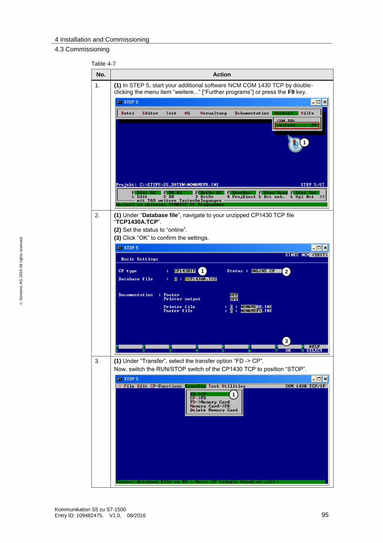
4 Installation and Commissioning
4.3 Commissioning
Kommunikation S5 zu S7-1500 Entry ID: 109482475, V1.0, 08/2016 95
S
iem
en
s A
G 2
91
6 A
ll ri
gh
ts r
ese
rve
d
Table 4-7
No. Action
1. (1) In STEP 5, start your additional software NCM COM 1430 TCP by double-clicking the menu item “weitere...” [“Further programs”] or press the F9 key.
2. (1) Under “Database file”, navigate to your unzipped CP1430 TCP file “TCP1430A.TCP”.
(2) Set the status to “online”.
(3) Click “OK” to confirm the settings.
3. (1) Under “Transfer”, select the transfer option “FD -> CP”.
Now, switch the RUN/STOP switch of the CP1430 TCP to position “STOP”.
1 2
3
1
1

4 Installation and Commissioning
4.3 Commissioning
Kommunikation S5 zu S7-1500 Entry ID: 109482475, V1.0, 08/2016 96
S
iem
en
s A
G 2
91
6 A
ll ri
gh
ts r
ese
rve
d
No. Action
4. (1) Check whether “TCP1430A.TCP” has been set for “Source file” and start transfer by clicking “Total” (2).
5. After having loaded the der CP1430 TCP, switch the RUN/STOP switch to position “RUN” again. The CP will change to the RUN mode (RUN LED) only, if synchronization occurs via a restart of the CPU.
After the CPU and the CP have been loaded, the SIMATIC S5 can be started via the RUN/STOP switch of the CPU. Error-free startup and synchronization of the CP1430 TCP can be recognized from the CPU and the CP1430 TCP being in RUN mode.
1
2

5 Operating the Application
5.1 Scenario 1 – Communication via FETCH/WRITE and CP1543-1
Kommunikation S5 zu S7-1500 Entry ID: 109482475, V1.0, 08/2016 97
S
iem
en
s A
G 2
91
6 A
ll ri
gh
ts r
ese
rve
d
5 Operating the Application The following chapter describes the operation as well as the test and diagnostic functions of the different scenarios.
Prerequisites
The SIMATIC S5-CPU program and the CP1430 TCP connection configuration include all example scenarios. The required S5 program blocks and the
corresponding functions are enabled via enable bits after loading the S5 program.
For successfully testing a scenario,
the corresponding enable bit in the SIMATIC S5-CPU must be set,
the corresponding SIMATIC S7-1500 station must be loaded,
the corresponding enable bit in the SIMATIC S7-CPU must be set where necessary.
Table 5-1
Scen. S5-CPU enable bit
S7-CPU Enable bit
S7 station name Description
1 M 130.5 - PLC_Sz1_F-W_S5-CP1430TCP
Communication via FETCH/WRITE and CP1543-1
2a M 130.3 E 0.1 PLC_Sz2_S-R_CPU_ID5_ID105
Communication via programmed Open User Communication (single instruction) and internal CPU interface
2b M 130.4 E 0.2 Communication via parameterized Open User Communication (single instruction) and internal CPU interface
3 M 130.2 E 0.1 PLC_Sz3_S-R_CP_TRCV_C_ID7
Communication via programmed Open User Communication (compact instruction) and CP1543-1
4a M 130.0 E 0.1 PLC_Sz4_S-R_CP_ID4_ID104
Communication via programmed Open User Communication (single instructions) and CP1543-1
4b M 130.1 E 0.2 Communication via parameterized Open User Communication (single instructions) and CP1543-1
5 M 130.6 E 0.1 PLC_Sz5_S-R_CPU_TSEND_C_ID6
Communication via programmed Open User Communication (compact instruction) and internal CPU interface
5.1 Scenario 1 – Communication via FETCH/WRITE and CP1543-1
Prerequisite
Table 5-2
Loaded S7-1500 station Activated enable bit in S5-CPU
PLC_Sz1_passive_F-W_S5-CP1430TCP M 130.5
Activate the corresponding enable bit in the SIMATIC S5-CPU via the “BB1” watch table.

5 Operating the Application
5.1 Scenario 1 – Communication via FETCH/WRITE and CP1543-1
Kommunikation S5 zu S7-1500 Entry ID: 109482475, V1.0, 08/2016 98
S
iem
en
s A
G 2
91
6 A
ll ri
gh
ts r
ese
rve
d
In this case, the SIMATIC S5 sets up the communication automatically. As, in this scenario, the SIMATIC S7-1500 station is absolutely passive, no explicit enable must be set there.
Test and diagnostics of communication in the SIMATIC S7-1500
To monitor the FETCH and WRITE functions in the SIMATIC S7-1500, call the watch table “BEO_Sz1_Fetch-Write” in TIA Portal.
The ongoing communication (continuous count value) can be monitored via the data areas of the FETCH (1) and WRITE areas (2) as well as via the output byte
(AB1) of the S7-1500.
Figure 5-1
Test and diagnostics of communication in the SIMATIC S5
To monitor the FETCH and WRITE functions in the SIMATIC S5-CPU, call the watch table “BB4” in STEP 5.
The count value (4) is cyclically written in the S7-1500 CPU every second and the mirrored incremented value is read back via the FETCH connection (1).
The communication and connection status of the FETCH (2) and WRITE functions (3) can be evaluated via the indicator words (ANZW) of the HTBs.
1
2

5 Operating the Application
5.2 Scenario 2a – Communication via parameterized OUC (single instructions) and internal CPU interface
Kommunikation S5 zu S7-1500 Entry ID: 109482475, V1.0, 08/2016 99
S
iem
en
s A
G 2
91
6 A
ll ri
gh
ts r
ese
rve
d
5.2 Scenario 2a – Communication via parameterized OUC (single instructions) and internal CPU interface
Prerequisite
Table 5-3
Loaded S7-1500 station
Enable bit S7-1500 CPU for scenario 2a
Activated enable bit (S5-CPU)
PLC_Sz2_S-R_CPU_ID5_ID105 E 0.1 M 130.3
Activate the corresponding enable bit in the SIMATIC S5-CPU via the “BB1” watch table.
As, in this case, the S7-1500 program contains the two example scenarios 2a and 2b, you can activate scenario 2a via the enable bit E 0.1.
Now, the connection will be established by the SIMATIC S7 station.
Test and diagnostics of communication in the SIMATIC S7-1500
The bidirectional data exchange (continuous count value) can be monitored via the output byte (AB1) of the S7-1500.
To monitor the ongoing communication and the status of the send and receive blocks in the SIMATIC S7-1500, call the watch table “BEO_Sz2_ID105” in TIA Portal.
1
2
3
4

5 Operating the Application
5.2 Scenario 2a – Communication via parameterized OUC (single instructions) and internal CPU interface
Kommunikation S5 zu S7-1500 Entry ID: 109482475, V1.0, 08/2016 100
S
iem
en
s A
G 2
91
6 A
ll ri
gh
ts r
ese
rve
d
Please refer to the “online” help for error states or status displays of the OUC blocks.
The status of the connection can also be checked in the S7-1500 station by means of the online functions of TIA Portal.
1. In TIA Portal of the station, call the “Device configuration” of this scenario.
2. Go to the station in “online” mode via the “Go online” option in the menu bar.
3. In the “Network view” (1), select the station “PLC_Sz2_S-R_CPU_ID105” (2) and go to the “Connections” tab (3).
4. In the “Connections” tab (3), select the parameterized ISO-on-TCP connection
with the local ID “105”.
5. In the “Diagnostics” tab, go to the “Connection information” (4).
6. Under “Connection details”, an established connection can be recognized from a green marking in the “Online status” (5). In this section, further details of the connection diagnostics are available.
1
2
4
3
5
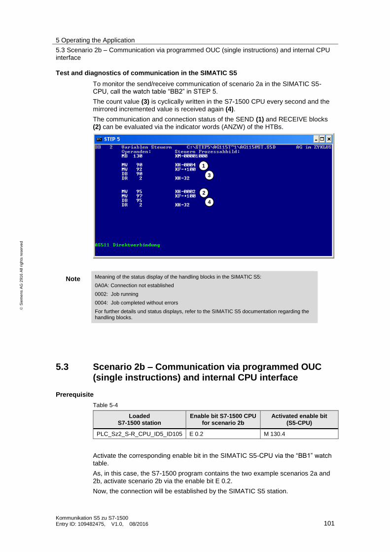
5 Operating the Application
5.3 Scenario 2b – Communication via programmed OUC (single instructions) and internal CPU interface
Kommunikation S5 zu S7-1500 Entry ID: 109482475, V1.0, 08/2016 101
S
iem
en
s A
G 2
91
6 A
ll ri
gh
ts r
ese
rve
d
Test and diagnostics of communication in the SIMATIC S5
To monitor the send/receive communication of scenario 2a in the SIMATIC S5-CPU, call the watch table “BB2” in STEP 5.
The count value (3) is cyclically written in the S7-1500 CPU every second and the mirrored incremented value is received again (4).
The communication and connection status of the SEND (1) and RECEIVE blocks (2) can be evaluated via the indicator words (ANZW) of the HTBs.
Note Meaning of the status display of the handling blocks in the SIMATIC S5:
0A0A: Connection not established
0002: Job running
0004: Job completed without errors
For further details und status displays, refer to the SIMATIC S5 documentation regarding the handling blocks.
5.3 Scenario 2b – Communication via programmed OUC (single instructions) and internal CPU interface
Prerequisite
Table 5-4
Loaded S7-1500 station
Enable bit S7-1500 CPU for scenario 2b
Activated enable bit (S5-CPU)
PLC_Sz2_S-R_CPU_ID5_ID105 E 0.2 M 130.4
Activate the corresponding enable bit in the SIMATIC S5-CPU via the “BB1” watch table.
As, in this case, the S7-1500 program contains the two example scenarios 2a and 2b, activate scenario 2b via the enable bit E 0.2.
Now, the connection will be established by the SIMATIC S5 station.
1
2
3
4
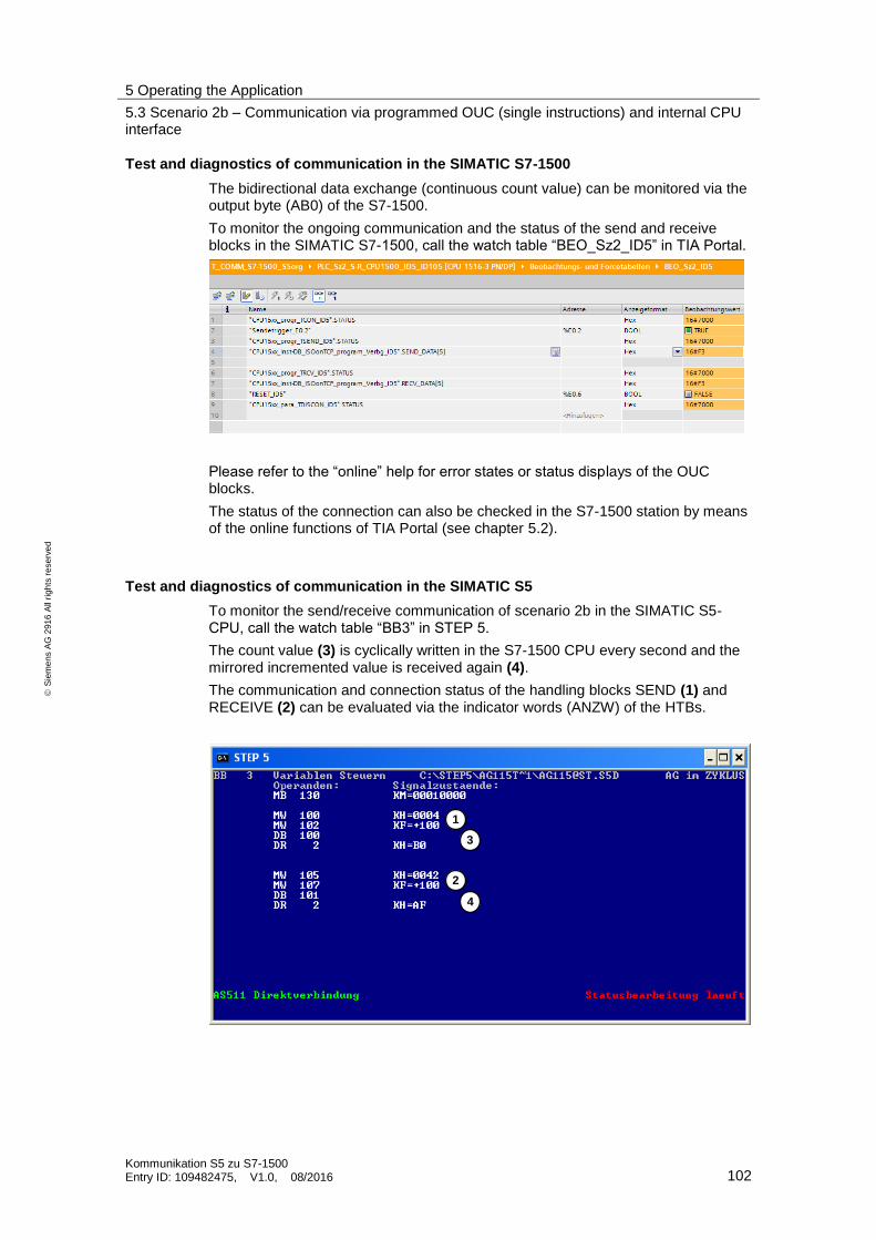
5 Operating the Application
5.3 Scenario 2b – Communication via programmed OUC (single instructions) and internal CPU interface
Kommunikation S5 zu S7-1500 Entry ID: 109482475, V1.0, 08/2016 102
S
iem
en
s A
G 2
91
6 A
ll ri
gh
ts r
ese
rve
d
Test and diagnostics of communication in the SIMATIC S7-1500
The bidirectional data exchange (continuous count value) can be monitored via the output byte (AB0) of the S7-1500.
To monitor the ongoing communication and the status of the send and receive blocks in the SIMATIC S7-1500, call the watch table “BEO_Sz2_ID5” in TIA Portal.
Please refer to the “online” help for error states or status displays of the OUC blocks.
The status of the connection can also be checked in the S7-1500 station by means of the online functions of TIA Portal (see chapter 5.2).
Test and diagnostics of communication in the SIMATIC S5
To monitor the send/receive communication of scenario 2b in the SIMATIC S5-CPU, call the watch table “BB3” in STEP 5.
The count value (3) is cyclically written in the S7-1500 CPU every second and the mirrored incremented value is received again (4).
The communication and connection status of the handling blocks SEND (1) and RECEIVE (2) can be evaluated via the indicator words (ANZW) of the HTBs.
1
2
3
4

5 Operating the Application
5.4 Scenario 3 – Communication via programmed OUC (compact instruction) and CP1543-1 interface
Kommunikation S5 zu S7-1500 Entry ID: 109482475, V1.0, 08/2016 103
S
iem
en
s A
G 2
91
6 A
ll ri
gh
ts r
ese
rve
d
5.4 Scenario 3 – Communication via programmed OUC (compact instruction) and CP1543-1 interface
Prerequisite
Loaded S7-1500 station
Enable bit S7-1500 CPU for scenario 3
Activated enable bit (S5-CPU)
PLC_Sz3_S-R_CP_TRCV_C_ID7 E 0.1 M 130.2
Activate the corresponding enable bit in the SIMATIC S5-CPU via the “BB1” watch table.
For scenario 3, the corresponding S7-1500 program can be activated via the enable bit E 0.1.
Now, the connection will be established by the SIMATIC S7 station.
Test and diagnostics of communication in the SIMATIC S7-1500
The bidirectional data exchange (continuous count value) can be monitored via the output byte (AB0) of the S7-1500.
To monitor the ongoing communication and the status of the send and receive blocks in the SIMATIC S7-1500, call the watch table “BEO_Sz3_ID7” in TIA Portal. There, you can monitor the last error status displays of the OUC blocks TSEND (1) and TRCV_C (2).
If the TRCV_C instruction has been executed successfully or with errors, the status of the TRCV_C instruction will be stored in the “DB_FC_RECV”.STATUS_SAVE variable. The status provides information on the reason why the data have not been received successfully.
Test and diagnostics of communication in the SIMATIC S5
To monitor the send/receive communication of scenario 3 in the SIMATIC S5-CPU, call the watch table “BB33” in STEP 5.
The count value (3) is cyclically written in the S7-1500 CPU every second and the mirrored incremented value is received again (4).
The communication and connection status of the handling blocks SEND (1) and RECEIVE (2) can be evaluated via the indicator words (ANZW) of the HTBs.
1
2

5 Operating the Application
5.4 Scenario 3 – Communication via programmed OUC (compact instruction) and CP1543-1 interface
Kommunikation S5 zu S7-1500 Entry ID: 109482475, V1.0, 08/2016 104
S
iem
en
s A
G 2
91
6 A
ll ri
gh
ts r
ese
rve
d
Note A programmed OUC communication (via compact instruction) means that the connection is established/disconnected and the data are received using the OUC block TRCV_C via the user program.
However, the data are sent via the standard OUC block TSEND.
1
2
3
4

5 Operating the Application
5.5 Scenario 4a – Communication via programmed OUC (single instructions) and CP1543-1
Kommunikation S5 zu S7-1500 Entry ID: 109482475, V1.0, 08/2016 105
S
iem
en
s A
G 2
91
6 A
ll ri
gh
ts r
ese
rve
d
5.5 Scenario 4a – Communication via programmed OUC (single instructions) and CP1543-1
Prerequisite
Loaded S7-1500 station
Enable bit S7-1500 CPU for scenario 4a
Activated enable bit (S5-CPU)
PLC_Sz4_S-R_CP_ID4_ID104 E 0.1 M 130.0
Activate the corresponding enable bit in the SIMATIC S5-CPU via the “BB1” watch table.
As, in this case, the S7-1500 program contains the two example scenarios 4a and 4b, activate scenario 4a via the enable bit E 0.1.
Now, the connection will be established by the SIMATIC S5 station.
Test and diagnostics of communication in the SIMATIC S7-1500
The bidirectional data exchange (continuous count value) can be monitored via the output byte (AB1) of the S7-1500.
To monitor the ongoing communication and the status of the send and receive blocks in the SIMATIC S7-1500, call the watch table “BEO_Sz2_ID104” in TIA Portal.
Please refer to the “online” help for error states or status displays of the OUC blocks.
Figure5-2
The status of the connection can also be checked in the S7-1500 station by means of the online functions of TIA Portal.
1. In TIA Portal of the station, call the “Device configuration” of this scenario.
2. Go to the station in “online” mode via the “Go online” option in the menu bar.
3. In the “Network view” (1), select the station “PLC_Sz4_S-R_CPU_ID104” (2) and go to the “Connections” tab (3).
4. In the “Connections” tab (3), select the parameterized ISO-on-TCP connection with the local ID “104”.
5. In the “Diagnostics” tab, go to the “Connection information” (4).

5 Operating the Application
5.5 Scenario 4a – Communication via programmed OUC (single instructions) and CP1543-1
Kommunikation S5 zu S7-1500 Entry ID: 109482475, V1.0, 08/2016 106
S
iem
en
s A
G 2
91
6 A
ll ri
gh
ts r
ese
rve
d
Under “Connection details”, an established connection via the CP1543-1 can be recognized from a green marking in the “Online status” (5). In this section, further details of the connection diagnostics are available.
Test and diagnostics of communication in the SIMATIC S5
To monitor the send/receive communication of scenario 2a in the SIMATIC S5-CPU, call the watch table “BB12” in STEP 5.
The count value (3) is cyclically written in the S7-1500 CPU every second and the mirrored incremented value is received again (4).
The communication and connection status of the SEND (1) and RECEIVE blocks (2) can be evaluated via the indicator words (ANZW) of the HTBs.
1
2
3
4
1
2
3
4
5

5 Operating the Application
5.6 Scenario 4b – Communication via parameterized OUC (single instructions) and CP1543-1
Kommunikation S5 zu S7-1500 Entry ID: 109482475, V1.0, 08/2016 107
S
iem
en
s A
G 2
91
6 A
ll ri
gh
ts r
ese
rve
d
5.6 Scenario 4b – Communication via parameterized OUC (single instructions) and CP1543-1
Prerequisite
Loaded S7-1500 station
Enable bit S7-1500 CPU for scenario 4b
Activated enable bit (S5-CPU)
PLC_Sz4_S-R_CP_ID4_ID104 E 0.2 M 130.1
Activate the corresponding enable bit in the SIMATIC S5-CPU via the “BB1” watch table.
As, in this case, the S7-1500 program contains the two example scenarios 4a and 4b, activate scenario 4b via the enable bit E 0.2.
Now, the connection will be established by the SIMATIC S5 station.
Test and diagnostics of communication in the SIMATIC S7-1500
The bidirectional data exchange (continuous count value) can be monitored via the output byte (AB0) of the S7-1500.
To monitor the ongoing communication and the status of the send and receive blocks in the SIMATIC S7-1500, call the watch table “BEO_Sz2_ID4” in TIA Portal.
Test and diagnostics of communication in the SIMATIC S5
To monitor the send/receive communication of scenario 2b in the SIMATIC S5-CPU, call the watch table “BB13” in STEP 5.
The count value (3) is cyclically written in the S7-1500 CPU every second and the mirrored incremented value is received again (4).
The communication and connection status of the handling blocks SEND (1) and RECEIVE (2) can be evaluated via the indicator words (ANZW) of the HTBs.

5 Operating the Application
5.7 Scenario 5 – Communication via programmed OUC (compact instructions) and internal CPU interface
Kommunikation S5 zu S7-1500 Entry ID: 109482475, V1.0, 08/2016 108
S
iem
en
s A
G 2
91
6 A
ll ri
gh
ts r
ese
rve
d
5.7 Scenario 5 – Communication via programmed OUC (compact instructions) and internal CPU interface
Prerequisite
Loaded S7-1500 station
Enable bit S7-1500 CPU for scenario 4b
Activated enable bit (S5-CPU)
PLC_Sz5_S-R_CPU_TSEND_C_ID6 E 0.1 M 130.6
Activate the corresponding enable bit in the SIMATIC S5-CPU via the “BB1” watch table.
For scenario 5, the corresponding S7-1500 program can be activated via the enable bit E 0.1.
Now, the connection will be established by the SIMATIC S7 station.
Test and diagnostics of communication in the SIMATIC S7-1500
The bidirectional data exchange (continuous count value) can be monitored via the output byte (AB0) of the S7-1500.
To monitor the ongoing communication and the status of the send and receive blocks in the SIMATIC S7-1500, call the watch table “BEO_Sz5_ID6” in TIA Portal. There, you can monitor the last error status displays of the OUC blocks TSEND_C (1) and TRCV (2).
If the TSEND_C instruction has been executed successfully or with errors, the status of the TSEND_C instruction will be stored in the “DB_FC_SEND”.STATUS_SAVE variable. The status provides information on the reason why the send job is not running.
1
2
3
4

5 Operating the Application
5.7 Scenario 5 – Communication via programmed OUC (compact instructions) and internal CPU interface
Kommunikation S5 zu S7-1500 Entry ID: 109482475, V1.0, 08/2016 109
S
iem
en
s A
G 2
91
6 A
ll ri
gh
ts r
ese
rve
d
Test and diagnostics of communication in the SIMATIC S5
To monitor the send/receive communication of scenario 3 in the SIMATIC S5-CPU, call the watch table “BB55” in STEP 5.
The count value (3) is cyclically written in the S7-1500 CPU every second and the mirrored incremented value is received again (4).
The communication and connection status of the handling blocks SEND (1) and RECEIVE (2) can be evaluated via the indicator words (ANZW) of the HTBs.
1
2
1
2
3
4

6 Links & Literature
Kommunikation S5 zu S7-1500 Entry ID: 109482475, V1.0, 08/2016 110
S
iem
en
s A
G 2
91
6 A
ll ri
gh
ts r
ese
rve
d
6 Links & Literature Table 6-1
Topic
\1\ Siemens Industry Online Support
https://support.industry.siemens.com
\2\ Download page of the entry https://support.industry.siemens.com/cs/ww/en/view/109482475
7 History
Table 7-1
Version Date Modifications
V1.0 07/2016 First version