application design patterns catalogue
TRANSCRIPT

Application Design Patterns CatalogueAUTOSAR CP R20-11
Document Title Application Design PatternsCatalogue
Document Owner AUTOSAR
Document Responsibility AUTOSAR
Document Identification No 672
Document Status published
Part of AUTOSAR Standard Classic Platform
Part of Standard Release R20-11
Document Change HistoryDate Release Changed by Description
2020-11-30 R20-11AUTOSARReleaseManagement
• Signal quality states introduction• Extension of definition of electrical
sensor interface
2019-11-28 R19-11AUTOSARReleaseManagement
• Subfunctions per layer defined• Capability information introduced• FAQ and known issues section
implemented• Separation of Sensor and Actuator in
namespace• Changed Document Status from
Final to published
2018-10-31 4.4.0AUTOSARReleaseManagement
• Editorial changes
2017-12-08 4.3.1AUTOSARReleaseManagement
• Editorial changes
2016-11-30 4.3.0AUTOSARReleaseManagement
• generalization of arbitration pattern,three examples: several setpointrequesters, several providers ofestimated values, several providersof consolidated values• minor changes
1 of 68 Document ID 672: AUTOSAR_TR_AIDesignPatternsCatalogue

Application Design Patterns CatalogueAUTOSAR CP R20-11
2015-07-31 4.2.2AUTOSARReleaseManagement
• reconsideration of signal definitionsand tailored pattern for smartactuators and actuators with nofeedback loop• specification items added• minor changes
2014-10-31 4.2.1AUTOSARReleaseManagement
• First Release of document. Patternscovered:
– Sensor and Actuator Pattern– Arbitration of Several Set-point
Requester Pattern• Previously published as part of
EXP_AIPowertrain
2 of 68 Document ID 672: AUTOSAR_TR_AIDesignPatternsCatalogue

Application Design Patterns CatalogueAUTOSAR CP R20-11
Disclaimer
This work (specification and/or software implementation) and the material contained init, as released by AUTOSAR, is for the purpose of information only. AUTOSAR and thecompanies that have contributed to it shall not be liable for any use of the work.
The material contained in this work is protected by copyright and other types of intel-lectual property rights. The commercial exploitation of the material contained in thiswork requires a license to such intellectual property rights.
This work may be utilized or reproduced without any modification, in any form or byany means, for informational purposes only. For any other purpose, no part of the workmay be utilized or reproduced, in any form or by any means, without permission inwriting from the publisher.
The work has been developed for automotive applications only. It has neither beendeveloped, nor tested for non-automotive applications.
The word AUTOSAR and the AUTOSAR logo are registered trademarks.
3 of 68 Document ID 672: AUTOSAR_TR_AIDesignPatternsCatalogue

Application Design Patterns CatalogueAUTOSAR CP R20-11
Table of Contents
1 Introduction 8
1.1 Document conventions . . . . . . . . . . . . . . . . . . . . . . . . . . . 81.2 Requirements Tracing . . . . . . . . . . . . . . . . . . . . . . . . . . . 10
2 About Patterns 11
2.1 Types of Pattern . . . . . . . . . . . . . . . . . . . . . . . . . . . . . . . 112.2 Describing Patterns . . . . . . . . . . . . . . . . . . . . . . . . . . . . . 11
3 Sensor and Actuator Pattern 13
3.1 Motivation . . . . . . . . . . . . . . . . . . . . . . . . . . . . . . . . . . 133.2 Also Known As . . . . . . . . . . . . . . . . . . . . . . . . . . . . . . . 133.3 Applicability . . . . . . . . . . . . . . . . . . . . . . . . . . . . . . . . . 133.4 Solution . . . . . . . . . . . . . . . . . . . . . . . . . . . . . . . . . . . 143.5 Naming . . . . . . . . . . . . . . . . . . . . . . . . . . . . . . . . . . . 183.6 Example . . . . . . . . . . . . . . . . . . . . . . . . . . . . . . . . . . . 23
3.6.1 Throttle Valve . . . . . . . . . . . . . . . . . . . . . . . . . . . 233.6.2 Turbo Charger . . . . . . . . . . . . . . . . . . . . . . . . . . 243.6.3 Turbo Charger with Stages and Banks . . . . . . . . . . . . . 253.6.4 Actuator without Feedback Loop . . . . . . . . . . . . . . . . 263.6.5 Standard Sensor . . . . . . . . . . . . . . . . . . . . . . . . . 273.6.6 Standard Sensor for Environment Temperature . . . . . . . . 283.6.7 Distributing Device Abstraction . . . . . . . . . . . . . . . . . 29
3.7 Sample Code and Model . . . . . . . . . . . . . . . . . . . . . . . . . . 313.8 Typical location of some common function within the specified layers . 33
3.8.1 Virtual Device Coordinator (DevCoorrVirt) . . . . . . . . . . . 333.8.1.1 Conversion and linearization of physical requested
value . . . . . . . . . . . . . . . . . . . . . . . . . . . 343.8.1.2 DCM service / Diagnostic tester interface for basic
function test . . . . . . . . . . . . . . . . . . . . . . . 343.8.1.3 Cleaning / Ice breaking . . . . . . . . . . . . . . . . . 353.8.1.4 Dither of setpoint . . . . . . . . . . . . . . . . . . . . 353.8.1.5 Release function of setpoint . . . . . . . . . . . . . . 353.8.1.6 Coordination of activation and deactivation of the ac-
tuator . . . . . . . . . . . . . . . . . . . . . . . . . . 353.8.2 Actuator Device Driver (DevDrvrActr) . . . . . . . . . . . . . 36
3.8.2.1 Dither of output value . . . . . . . . . . . . . . . . . . 363.8.2.2 Release function of output value . . . . . . . . . . . 363.8.2.3 Limitation . . . . . . . . . . . . . . . . . . . . . . . . 373.8.2.4 Feed forward controller . . . . . . . . . . . . . . . . . 373.8.2.5 Closed loop controller . . . . . . . . . . . . . . . . . 373.8.2.6 Set point limitation . . . . . . . . . . . . . . . . . . . 373.8.2.7 Set point gradient limitation . . . . . . . . . . . . . . 373.8.2.8 Control deviation monitoring . . . . . . . . . . . . . . 373.8.2.9 Capability . . . . . . . . . . . . . . . . . . . . . . . . 38
4 of 68 Document ID 672: AUTOSAR_TR_AIDesignPatternsCatalogue

Application Design Patterns CatalogueAUTOSAR CP R20-11
3.8.3 Electrical Actuator Driver (DrvrActrElec) . . . . . . . . . . . . 393.8.3.1 Power stage monitoring . . . . . . . . . . . . . . . . 40
3.8.4 Virtual Device Driver (DevSnsrVirt) . . . . . . . . . . . . . . . 403.8.4.1 Substitution . . . . . . . . . . . . . . . . . . . . . . . 403.8.4.2 Inertia compensation . . . . . . . . . . . . . . . . . . 413.8.4.3 Signal qualifier evaluation . . . . . . . . . . . . . . . 413.8.4.4 DCM service / Diagnostic tester interface for basic
function test . . . . . . . . . . . . . . . . . . . . . . . 413.8.4.5 Plausibilization . . . . . . . . . . . . . . . . . . . . . 41
3.8.5 Sensor Device Driver (DevDrvrSnsr) . . . . . . . . . . . . . . 423.8.5.1 High level filtering . . . . . . . . . . . . . . . . . . . . 423.8.5.2 Offset adaption . . . . . . . . . . . . . . . . . . . . . 423.8.5.3 Zero point adaption . . . . . . . . . . . . . . . . . . . 433.8.5.4 Drift detection . . . . . . . . . . . . . . . . . . . . . . 433.8.5.5 Conversion . . . . . . . . . . . . . . . . . . . . . . . 433.8.5.6 Physical signal gradient calculation . . . . . . . . . . 433.8.5.7 Physical signal gradient check . . . . . . . . . . . . . 433.8.5.8 Stuck check diagnosis . . . . . . . . . . . . . . . . . 433.8.5.9 Physical signal range check . . . . . . . . . . . . . . 44
3.8.6 Electrical Sensor Driver (DrvrSnsrElec) . . . . . . . . . . . . 443.8.6.1 Basic filter . . . . . . . . . . . . . . . . . . . . . . . . 443.8.6.2 Voltage compensation . . . . . . . . . . . . . . . . . 453.8.6.3 Electrical diagnosis . . . . . . . . . . . . . . . . . . . 45
3.9 Known Issues . . . . . . . . . . . . . . . . . . . . . . . . . . . . . . . . 453.10 FAQ . . . . . . . . . . . . . . . . . . . . . . . . . . . . . . . . . . . . . 453.11 Known Uses . . . . . . . . . . . . . . . . . . . . . . . . . . . . . . . . . 463.12 Related Patterns . . . . . . . . . . . . . . . . . . . . . . . . . . . . . . 463.13 Anti-Patterns One Should be Aware of . . . . . . . . . . . . . . . . . . 463.14 Further Readings . . . . . . . . . . . . . . . . . . . . . . . . . . . . . . 46
4 Arbitration between several requesters or providers 47
4.1 Problem . . . . . . . . . . . . . . . . . . . . . . . . . . . . . . . . . . . 474.2 Applicability . . . . . . . . . . . . . . . . . . . . . . . . . . . . . . . . . 474.3 Solution . . . . . . . . . . . . . . . . . . . . . . . . . . . . . . . . . . . 474.4 Examples . . . . . . . . . . . . . . . . . . . . . . . . . . . . . . . . . . 50
4.4.1 Several Setpoint Requesters . . . . . . . . . . . . . . . . . . 504.4.2 Several Providers of Consolidated Values . . . . . . . . . . . 514.4.3 Several Providers of Estimated Values . . . . . . . . . . . . . 53
4.5 Sample Code and Model . . . . . . . . . . . . . . . . . . . . . . . . . . 554.6 Known Uses . . . . . . . . . . . . . . . . . . . . . . . . . . . . . . . . . 554.7 Related Patterns . . . . . . . . . . . . . . . . . . . . . . . . . . . . . . 55
5 Signal Quality States 56
5.1 Problem . . . . . . . . . . . . . . . . . . . . . . . . . . . . . . . . . . . 565.2 Applicability . . . . . . . . . . . . . . . . . . . . . . . . . . . . . . . . . 565.3 Solution . . . . . . . . . . . . . . . . . . . . . . . . . . . . . . . . . . . 56
5 of 68 Document ID 672: AUTOSAR_TR_AIDesignPatternsCatalogue
Application Design Patterns CatalogueAUTOSAR CP R20-11
A Change History 58
A.1 Change History AUTOSAR R4.3.0 . . . . . . . . . . . . . . . . . . . . 58A.1.1 Added Constraints in R4.3.0 . . . . . . . . . . . . . . . . . . 58A.1.2 Changed Constraints in R4.3.0 . . . . . . . . . . . . . . . . . 58A.1.3 Deleted Constraints in R4.3.0 . . . . . . . . . . . . . . . . . . 58A.1.4 Added Specification Items in R4.3.0 . . . . . . . . . . . . . . 58A.1.5 Changed Specification Items in R4.3.0 . . . . . . . . . . . . 58A.1.6 Deleted Specification Items in R4.3.0 . . . . . . . . . . . . . 58
A.2 Change History AUTOSAR R4.2.2 . . . . . . . . . . . . . . . . . . . . 58A.2.1 Added Constraints in R4.2.2 . . . . . . . . . . . . . . . . . . 58A.2.2 Changed Constraints in R4.2.2 . . . . . . . . . . . . . . . . . 59A.2.3 Deleted Constraints in R4.2.2 . . . . . . . . . . . . . . . . . . 59A.2.4 Added Specification Items in R4.2.2 . . . . . . . . . . . . . . 59A.2.5 Changed Specification Items in R4.2.2 . . . . . . . . . . . . 59A.2.6 Deleted Specification Items in R4.2.2 . . . . . . . . . . . . . 59
A.3 Change History AUTOSAR R4.2.1 . . . . . . . . . . . . . . . . . . . . 59A.3.1 Added Constraints in R4.2.1 . . . . . . . . . . . . . . . . . . 59A.3.2 Added Specification Items in R4.2.1 . . . . . . . . . . . . . . 59
B Mentioned Class Tables 60
6 of 68 Document ID 672: AUTOSAR_TR_AIDesignPatternsCatalogue

Application Design Patterns CatalogueAUTOSAR CP R20-11
References
[1] ANTLR parser generator V3
[2] Standardization TemplateAUTOSAR_TPS_StandardizationTemplate
[3] SW-C and System Modeling GuideAUTOSAR_TR_SWCModelingGuide
[4] XML Specification of Application InterfacesAUTOSAR_MOD_AISpecification
[5] Main RequirementsAUTOSAR_RS_Main
[6] Architectural Patternhttp://en.wikipedia.org/wiki/Architectural_pattern
[7] Software Design Patternhttp://en.wikipedia.org/wiki/Software_design_pattern
[8] Design Patternhttp://en.wikipedia.org/wiki/Design_Pattern
[9] Anti Patternhttp://en.wikipedia.org/wiki/Anti-pattern
[10] Software Design Pattern Templatehttp://c2.com/cgi/wiki?DesignPatternTemplate
[11] Secure Design Patternshttp://www.sei.cmu.edu/reports/09tr010.pdf
[12] Software Component TemplateAUTOSAR_TPS_SoftwareComponentTemplate
[13] Layered Software ArchitectureAUTOSAR_EXP_LayeredSoftwareArchitecture
7 of 68 Document ID 672: AUTOSAR_TR_AIDesignPatternsCatalogue

Application Design Patterns CatalogueAUTOSAR CP R20-11
1 Introduction
1.1 Document conventions
Technical terms (Class Names) are typeset in mono spaced font, e.g. FrameTrig-gering.
When defining name patterns the syntax defined according to ANTLR is used [1]. Thegrammar for name patterns as defined in [2], [TPS_STDT_00055], is used. In thefollowing we just list the most important placeholders that are used throughout thedocument:
anyName This represents a string which is valid shortName according to Identi-fier
anyNamePart This represents a string (([a-zA-Z0-9]|_[a-zA-Z0-9])*_?) which is validpart of a shortName.
Hint: The place holder "anyNamePart" shall not be used at the beginning of ashortName pattern to avoid invalid shortNames.
blueprintName This represents the shortName / shortLabel / symbol of the ap-plied blueprint
componentName This represents the shortName of the BSW module resp.ASW SwComponentType / ASW component prototype related to the derived ob-ject. "Related" mainly could be both, aggregating or referencing.
The placeholder componentName in particular supports multiple derivation ofa PortPrototypeBlueprint in the context of different software componenttypes resp. modules [TPS_STDT_00036].
componentTypeName This represents the shortName of the dedicated SwCompo-nentType.
componentPrototypeName This represents the shortName of the dedicatedSwComponentPrototype.
index This represents a numerical index applicable for example to arrays.
keyword This represents the abbrName of a keyword acting as a name part of theshort name [TPS_STDT_00004].
For a complete description see [2], [TPS_STDT_00055]. Additionally we assume thatthe naming rules as defined in [3] are fulfilled. If applicable and available the keywordsused in names are those standardized in [4].
Additionally we extend the grammar using the following place holders:
anyLongName This represents a string which is a valid longName.
8 of 68 Document ID 672: AUTOSAR_TR_AIDesignPatternsCatalogue

Application Design Patterns CatalogueAUTOSAR CP R20-11
Additionally we assume that [TR_SWNR_0064] is fulfilled. This means that thelong name starts with a capital letter and that all words except articles (e.g. ”a”,”the”), prepositions (e.g. ”at”, ”by”, ”to”) and conjunctions (e.g. ”and”, ”or”) startwith a capital letter as well.
anyLongNamePart This represents a string which is a valid part of a longName.
9 of 68 Document ID 672: AUTOSAR_TR_AIDesignPatternsCatalogue
Application Design Patterns CatalogueAUTOSAR CP R20-11
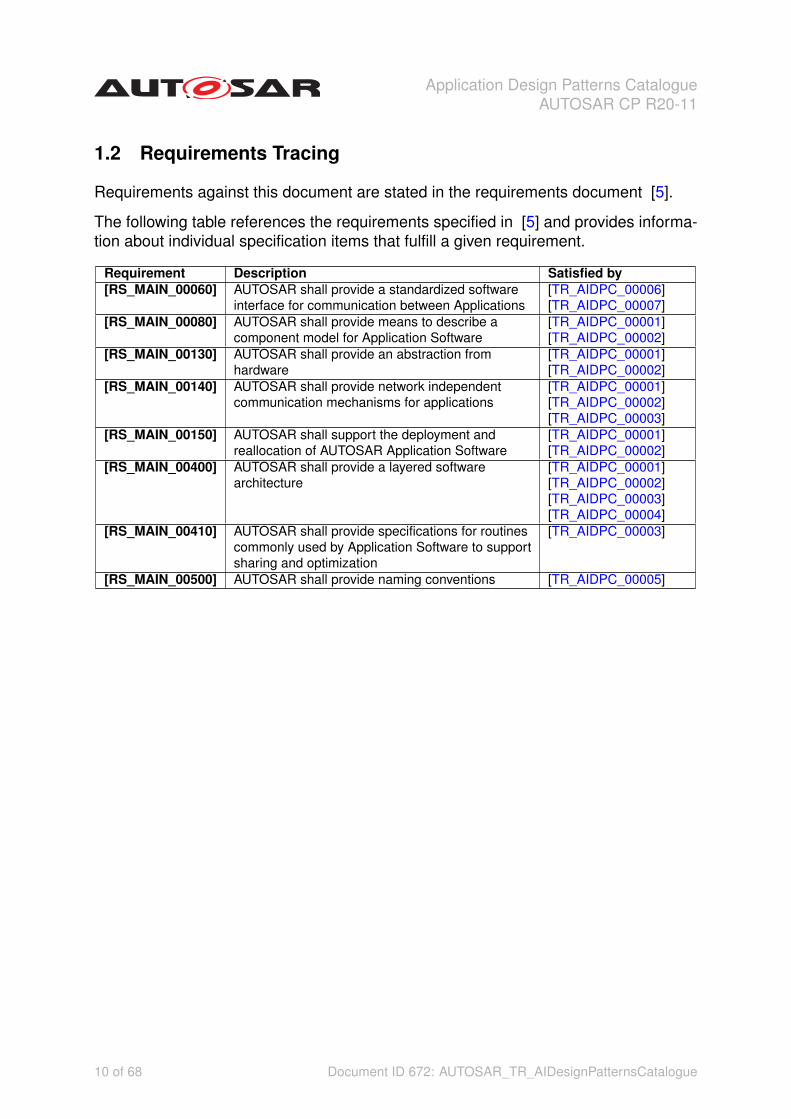
1.2 Requirements Tracing
Requirements against this document are stated in the requirements document [5].
The following table references the requirements specified in [5] and provides informa-tion about individual specification items that fulfill a given requirement.
Requirement Description Satisfied by[RS_MAIN_00060] AUTOSAR shall provide a standardized software
interface for communication between Applications[TR_AIDPC_00006][TR_AIDPC_00007]
[RS_MAIN_00080] AUTOSAR shall provide means to describe acomponent model for Application Software
[TR_AIDPC_00001][TR_AIDPC_00002]
[RS_MAIN_00130] AUTOSAR shall provide an abstraction fromhardware
[TR_AIDPC_00001][TR_AIDPC_00002]
[RS_MAIN_00140] AUTOSAR shall provide network independentcommunication mechanisms for applications
[TR_AIDPC_00001][TR_AIDPC_00002][TR_AIDPC_00003]
[RS_MAIN_00150] AUTOSAR shall support the deployment andreallocation of AUTOSAR Application Software
[TR_AIDPC_00001][TR_AIDPC_00002]
[RS_MAIN_00400] AUTOSAR shall provide a layered softwarearchitecture
[TR_AIDPC_00001][TR_AIDPC_00002][TR_AIDPC_00003][TR_AIDPC_00004]
[RS_MAIN_00410] AUTOSAR shall provide specifications for routinescommonly used by Application Software to supportsharing and optimization
[TR_AIDPC_00003]
[RS_MAIN_00500] AUTOSAR shall provide naming conventions [TR_AIDPC_00005]
10 of 68 Document ID 672: AUTOSAR_TR_AIDesignPatternsCatalogue

Application Design Patterns CatalogueAUTOSAR CP R20-11
2 About Patterns
This document gives an overview of the patterns defined in AUTOSAR for ease theusage of AUTOSAR architecture, AUTOSAR application interfaces and the AUTOSARmeta-model. The focus is on application software (ASW).
2.1 Types of Pattern
The following categories/classifications of patterns are distinguished:
Architectural Pattern An architectural pattern is a standard design in the field of soft-ware architecture. The concept of an architectural pattern has a broader scopethan the concept of design pattern. The architectural patterns address variousissues in software engineering, such as computer hardware performance limita-tions, high availability and minimization of a business risk [6].
Design Pattern In software engineering, a design pattern is a general reusable solu-tion to a commonly occurring problem within a given context in software design.A design pattern is not a finished design that can be transformed directly intosource or machine code. It is a description or template for how to solve a prob-lem that can be used in many different situations. Patterns are formalized bestpractices that the programmer must implement themselves in the application [7].
Solution Pattern A solution pattern describes a generic solution for a specific problemlike for example error handling or job scheduling [6].
An orthogonal classification of patterns is the following:
Design Patterns A design pattern in architecture and computer science is a formalway of documenting a solution to a design problem in a particular field of expertise[8].
Anti-Patterns In software engineering, an anti-pattern (or anti-pattern) is a patternused in social or business operations or software engineering that may be com-monly used but is ineffective and/or counterproductive in practice [9].
2.2 Describing Patterns
The description of the patterns in this document follow a predefined structure. Thisstructure was created based on the contents of the documents [7], [10], [11], [1], and[2].
A pattern is described in a separate section and the header of the particular patterncontains the name of the pattern and the pattern identification (standardized name):{pattern name} ({pattern identification})
11 of 68 Document ID 672: AUTOSAR_TR_AIDesignPatternsCatalogue

Application Design Patterns CatalogueAUTOSAR CP R20-11
At the very beginning of the section describing a specific pattern the classification isgiven as shown below:
Classification {type of pattern} Pattern
The type of the pattern is one of the categories described in section 2.1.
Section Mandatory Instruction Additional InformationProblem Yes The problem solved by the
design pattern and its gen-eral rationale and purpose.
None
Also Known As No Other names for the pattern,if any are known.
None
Applicability Yes A general description of thecharacteristics a systemmust have for the patternto be useful in the designor implementation of theprogram.
Indications: something you no-tice, hinting that this pattern maybe applicable Contraindications:something that would indicatethat this pattern would not be ap-plicable
Solution Yes A textual or graphical de-scription of the pattern. Thisprovides a detailed specifica-tion of the structural aspectsof the pattern, using appro-priate notations.
Also think about Overdose Ef-fect : what undesirable thinghappens if you keep applyingthe suggested action over andover and over and over.Also think about Side Effects:new problems that you might ex-pect to crop up upon applyingthe solution, or new issues thatcome to the fore.
Naming No Describes naming patternthat are usable or should beused in the context of the pat-tern.
Name pattern follow syntax de-fined according to ANTLR like itwas decided to use in [2], e.g. in[TPS_STDT_00055].
Example Yes Example how to apply thepattern.
None
Sample Code andModel
No Code or model providing anexample of how to implementthe pattern.
None
Known Uses No Examples of the use of thepattern, taken from existingsystems or literature.
None
Related Patterns No Other patterns that havesome relationship with thepattern; discussion of the dif-ferences between the patternand similar patterns.
Other patterns that relate, ei-ther superordinate, subordinate,competitor, or neighboring pat-terns, with references to wherethey can be found.
Anti-Patterns No Anti-Patterns you should beaware of.
None
Reading No Further material worthwhileto know.
None
Table 2.1: Pattern Description Template
12 of 68 Document ID 672: AUTOSAR_TR_AIDesignPatternsCatalogue

Application Design Patterns CatalogueAUTOSAR CP R20-11
3 Sensor and Actuator Pattern
Classification Design Pattern
3.1 Motivation
The Sensor/Actuator Design Pattern describes how to handle sensors or actuators thatare connected to an ECU in the context of an overall architecture.
The main intention of this pattern is standardizing application interfaces for SWC con-trolling sensors and actuators, it focuses on aspects of:
• Independence of application software from concrete sensors and actuators con-nected to a specific ECU.
• Reusable code between different sensors and actuators.
• Different code sharing cooperation models (software sharing), thus supportingdifferent business models.
• Deployment of functionality to different ECUs.
For standardizing interfaces it is useful to have an architectural design overview of asensor/actuator composition. Therefore it was decided to create an architectural de-sign pattern first and define the interface inside next. In a first step a layer modelcontaining the main interfaces between those layers is created. Then the most com-mon functions within the layers are defined and described for a common understandingin a second step. In the third step it is planned to describe also the interfaces in thesefunctions from step 2.
The pattern in general is a strong recommendation but is not mandatory to be followed.The interfaces which are standardized as a result from the pattern will be reservedexactly for the described usecase and shall not be used for other purpose even if thepattern is not followed.
3.2 Also Known As
This pattern is also known as Device Abstraction.
3.3 Applicability
[TR_AIDPC_00001] Access to Hardware by PSnsrAct d
The Device Abstraction is located above the RTE. It is a set of software componentsthat abstracts from the sensors and actuators connected to a specific ECU. It uses
13 of 68 Document ID 672: AUTOSAR_TR_AIDesignPatternsCatalogue

Application Design Patterns CatalogueAUTOSAR CP R20-11
sensor actuator software components, the only components above RTE that are al-lowed to access the ECU abstraction interface.c(RS_MAIN_00080, RS_MAIN_00130,RS_MAIN_00140, RS_MAIN_00150, RS_MAIN_00400)
In case direct access to the Micro controller is required because specific interruptsand/or complex Micro controller peripherals to fulfill the special functional and timingrequirements of the sensor evaluation or actuator control have to be implemented thispattern cannot be applied. Instead a complex driver implementation shall be used.
[TR_AIDPC_00002] Collaboration supported by PSnsrAct dThe Sensor/ActuatorDesign Pattern supports software sharing (=collaboration between various partners) ondifferent levels: Development partner one might deliver the sensors together with thebasic electrical driver software (DrvrSnsrElec), development partner two might deliverthe sensor device driver software (DevDrvrSnsr) and the third partner might develop thesubstitute models together with the virtual device drivers (DevSnsrVirt). There might bedifferent suppliers for the same Sensor/Actuator or there might be sensors/actuatorsfrom different vendors used within one and the same system.c(RS_MAIN_00080, RS_-MAIN_00130, RS_MAIN_00140, RS_MAIN_00150, RS_MAIN_00400)
In case software sharing shall not be supported it is also possible to just implementthe interfaces of the composition of a single sensor or actuator but not following theinternal three-level-architecture.
[TR_AIDPC_00003] Deployment/Relocation supported by PSnsrAct dTheSensor/Actuator-Pattern also supports different deployment scenarios to ECUs. OneECU might provide the measured value of a sensor whereas another ECU is imple-menting the model that calculates the estimated value that may substitute the mea-sured sensor value.c(RS_MAIN_00140, RS_MAIN_00400, RS_MAIN_00410)
Note: In general a pattern is not applied without any changes but with extension bycombining several patterns to one solution. For example:
• The composition pattern (splitting of component if they are getting too large andare not maintainable any longer) is combined with this pattern.
• The diagnosis pattern is combined with this pattern.
3.4 Solution
In Figure 3.1 that was taken from [12] an example of the signal flow for a lamp (actuator)and a velocity sensor is shown. This signal flow pattern is refined by this sensor/actu-ator pattern.
14 of 68 Document ID 672: AUTOSAR_TR_AIDesignPatternsCatalogue

Application Design Patterns CatalogueAUTOSAR CP R20-11
Figure 3.1: Sensor Actuator Signal Flow [12]
[TR_AIDPC_00004] Layers of PSnsrAct dThe solution is proposing a three-level lay-ering within a composition representing a sensor or actuator:
• electrical device driver layer,
• sensor/actuator device driver layer,
• virtual device driver layer.
c(RS_MAIN_00400)
In Figure 3.2 the overall structure of the pattern is shown. Recursive elements are op-tional. Closed loop controlled actuator and position feedback is included. The namingis simplified and will be explained in more detail later.
15 of 68 Document ID 672: AUTOSAR_TR_AIDesignPatternsCatalogue

Application Design Patterns CatalogueAUTOSAR CP R20-11
Figure 3.2: Sensor Actuator Pattern for Closed Loop
The application software can rely on the existence of the consolidated value. Theconsolidated value can be calculated from the
• estimated value,
• setpoint value,
• measured and/or raw value.
The calculation of the consolidated value via the setpoint or estimated value is usedin case of actuators without feedback loop. In Figure 3.8 an example of an actuatorwithout feedback loop calculating the consolidated value from the setpoint value isshown. Besides actuators with open loop control there are also smart actuators thatcan directly deal with the setpoint value itself. In this case the device driver actuatorSW-C and the electrical driver actuator SW-C are only routing the setpoint value since
16 of 68 Document ID 672: AUTOSAR_TR_AIDesignPatternsCatalogue

Application Design Patterns CatalogueAUTOSAR CP R20-11
the controlling of the actuator and thus the calculating of the output value etc. is realizedwithin the smart actuator itself. However, the two layers, electrical device layer anddevice driver layer, are additionally needed because of diagnosis etc.
The pattern can be tailored for a standard sensor. In this case the consolidated value(Consold) is provided and the estimated value (Estimd) is requested, see Figure 3.9.
The signal flow is shown in Figure 3.3: The electrical raw value is requested from theECU Abstraction. After basic filtering the signal is converted to a physical value repre-senting the measured value. If the measured value is not suitable for the application theestimated value might be chosen to be the consolidated value, i.e. the value that canbe used by the rest of the application software. Some applications request to explicitlyknow about the physical raw value. This is why this signal is also made available.
Figure 3.3: Signal Flow within Sensor and Actuator Pattern
Please be aware: SensorActuatorSwComponentTypes are the only componentsthat are allowed to access ECU Abstraction Software, namely EcuAbstraction-SwComponentType. This is shown in Figure 3.4 taken from [13]. Access is denotedby ”IO”.
17 of 68 Document ID 672: AUTOSAR_TR_AIDesignPatternsCatalogue

Application Design Patterns CatalogueAUTOSAR CP R20-11
Figure 3.4: Access to ECU Abstraction
3.5 Naming
[TR_AIDPC_00005] Naming within PSnsrAct dIn the following the semantic portprototype (blueprint) definition together with the name patterns are described.
The overall name pattern for port short names is described in grammar 3.1. In thefollowing these port (prototype blueprint) names are also referred to as signal names.In Table 3.1 additionally the pattern for the corresponding long names is given.c(RS_-MAIN_00500)
Listing 3.1: Name Pattern for Ports in Device Abstractiongrammar PSnsrActrPortNames;
portName: {’sensorActuatorSignal’} ;
sensorActuatorSignal: {anyName}{’sensorActuatorSignalType’} ;
sensorActuatorSignalType: ( ElecRaw | ElecBascFild | Raw | Measd | Consold | Estimd | Outp |
Sp | Reqd ) ;
18 of 68 Document ID 672: AUTOSAR_TR_AIDesignPatternsCatalogue

Application Design Patterns CatalogueAUTOSAR CP R20-11
anyName: (’keyword’)* ;
In case of a generic long name {anyLongNamePart} or {anyLongName}, resp., isempty.
Generic Signal Name Long Name Patternof Concrete Sen-sor/Actuator Signal(EN)
GenericLong Nameof Signal(EN)
AUTOSAR Definition
ElecRaw Electrical RawValue of {anyLong-NamePart}
ElectricalRaw Value
Electrical raw sensor value as provided by theECU Abstraction. Typically this value is unfil-tered. However, there are for example smartcomponents doing some filtering themselves.This signal can only be represented in volt-age, current, (period) time, binary value, fre-quency, dutycycle [12].
ElecBascFild Electrical Basic Fil-tered Value of {any-LongNamePart}
ElectricalBasic Fil-tered Value
Basic filtered electrical raw sensor value (e.g.maximum allowed phase shift is one schedul-ing raster or maximum 360 degree crankshaftrotation if exhaust gas pulsation dependent).Electrical representation of a technical signal[12]. This signal can only be represented involtage, current, (period) time, binary value,frequency, dutycycle.
Raw Raw Value of {any-LongNamePart}
Raw Value Physical raw/base sensor value. Sim-ple conversion of basic filtered electrical(ElecBascFild) to physical value.
Measd {anyLongName}(Measured)
MeasuredValue
Final filtered and offset corrected physicalsensor value. Physical sensor value/standardsensor value. The physical sensor value isthe linearized/filtered physical raw/base sen-sor value including offset. At this step a (sig-nificant) phase-shift could be possible.
Consold {anyLongName} Value Consolidated physical value, either a mea-sured value (Measd) or a modeled value(Estimd). Final filtered and offset correctedconsolidated actuator value/physical sensorvalue. Virtual physical sensor value/fusedsensor value that comes as close as possi-ble to the technical signal. In case of inabilityto provide a physical sensor value (e.g. fail-ure, implausibility or other reasons) a substi-tute value/default value or a frozen value isprovided.
Estimd {anyLongName}(Estimated)
EstimatedValue
Modelled value physical sensor value/stan-dard sensor value. Can be used as a replace-ment for final filtered and offset correctedphysical sensor value. The interface is op-tional.
19 of 68 Document ID 672: AUTOSAR_TR_AIDesignPatternsCatalogue

Application Design Patterns CatalogueAUTOSAR CP R20-11
Outp Output of {any-LongNamePart}
OutputValue
Final controller output (closed loop or openloop). It includes the necessary control ac-tions to reach the requested setpoint in thegiven system conditions.For example for realizing the requested ac-tuator position a precontrol impulse to over-come the static friction is needed. In case ofa smart actuator the output value might add adedicated initialization duty cycle to wakeupthe actuator.Typically expressed as percentage.
Sp Setpoint {anyLong-NamePart}
SetpointValue
Final actuator setpoint. Typically expressedas percentage.
Reqd Requested Set-point {anyLong-NamePart}
RequestedSetpoint
Final requested physical setpoint. Typicallyexpressed as percentage but could also beexpressed e.g. as factor.
Cpby Capability {any-LongNamePart}
Capability Provides the dynamic instant capability typi-cally based on output limitation but could alsocontain the limitation on rate of change of theconsolidated value. It is expressed as per-centage.
Table 3.1: Signal Names and Semantics
Some examples of short and long names for sensor/actuator signals or ports, resp.,are given in Table 3.2.
Short Name Class Long Name (EN)TrboChrgrReqd PortPrototype Requested Setpoint for Turbo ChargerConsold PortPrototype Consolidated ValueTrboChrgrStg3AtBnk2 FlatInstanceDescriptor Value of Turbo Charger at Third Stage
at Second BankTrboChrgr PortPrototype Value of Turbo Charger
Table 3.2: Port Names Examples
In grammar 3.2 the pattern for component types and component prototypes for theatomic components within a composition representing a sensor or an actuator is de-scribed.
In some cases there might be parts of the implementation that can be reused for dif-ferent sensors/actuators. Therefore the name pattern for the component type name ismore generic and does not necessarily contain the Sensor/Actuator name. In othercases the Sensor/Actuator names are not sufficient to make the component typenames unique so an additional identifier can be added to the component type name.
Listing 3.2: Name Pattern for Atomic Software Component Types in Device Abstractiongrammar PSnsrActrAtomicSwcShortName;
sensorActuatorComponentTypeName: sensorActuatorComponentName ;
20 of 68 Document ID 672: AUTOSAR_TR_AIDesignPatternsCatalogue

Application Design Patterns CatalogueAUTOSAR CP R20-11
sensorActuatorComponentPrototypeName: sensorActuatorComponentName ;
sensorActuatorComponentName: (Drvr{Device}Elec | DevDrvr{Device} | Dev{Device}Virt | DevCoorrVirt
)(’anyNamePart’) ;
Device: ( Snsr | Actr ) ;
anyNamePart: (’keyword’)* ;
In grammar 3.3 the pattern is more refined but still conforming to grammar 3.2 because”For” is a standardized keyword. Note: the refined grammar is following [TR_SWNR_-0034] that requests that field blocks are concatenated by adding an appropriate prepo-sition.
Listing 3.3: Refined Name Pattern for Atomic Software Component Types in Device Ab-stractiongrammar PSnsrActrAtomicSwcShortNameRefined;
sensorActuatorComponentTypeName: sensorActuatorComponentName ;
sensorActuatorComponentPrototypeName: sensorActuatorComponentName ;
sensorActuatorComponentName: (Drvr{deviceType}Elec | DevDrvr{deviceType} | Dev{deviceType}Virt |
DevCoorrVirt) ({device}) ;
deviceType: ( Snsr | Actr ) ;
device: ( For{sensor}(’anyNamePart’) | For{actuator}(’anyNamePart’) ) ;
sensor: ’anyName’ ;
actuator: ’anyName’ ;
anyName: (’keyword’)* ;
anyNamePart: (’keyword’)* ;
In grammar 3.4 the pattern for the corresponding English long names of the compo-nents is described.
21 of 68 Document ID 672: AUTOSAR_TR_AIDesignPatternsCatalogue
Application Design Patterns CatalogueAUTOSAR CP R20-11
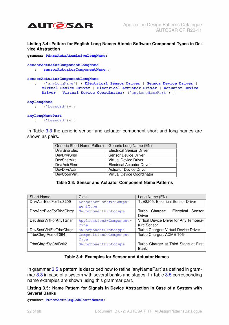
Listing 3.4: Pattern for English Long Names Atomic Software Component Types in De-vice Abstractiongrammar PSnsrActrAtomicSwcLongName;
sensorActuatorComponentLongName: sensorActuatorComponentName ;
sensorActuatorComponentLongName: (’anyLongName’) ( Electrical Sensor Driver | Sensor Device Driver |
Virtual Device Driver | Electrical Actuator Driver | Actuator DeviceDriver | Virtual Device Coordinator) (’anyLongNamePart’) ;
anyLongName: (’keyword’)* ;
anyLongNamePart: (’keyword’)* ;
In Table 3.3 the generic sensor and actuator component short and long names areshown as pairs.
Generic Short Name Pattern Generic Long Name (EN)DrvrSnsrElec Electrical Sensor DriverDevDrvrSnsr Sensor Device DriverDevSnsrVirt Virtual Device DriverDrvrActrElec Electrical Actuator DriverDevDrvrActr Actuator Device DriverDevCoorrVirt Virtual Device Coordinator
Table 3.3: Sensor and Actuator Component Name Patterns
Short Name Class Long Name (EN)DrvrActrElecForTle8209 SensorActuatorSwCompo-
nentTypeTLE8209: Electrical Sensor Driver
DrvrActrElecForTrboChrgr SwComponentPrototype Turbo Charger: Electrical SensorDriver
DevSnsrVirtForAnyTSnsr ApplicationSwComponent-Type
Virtual Device Driver for Any Tempera-ture Sensor
DevSnsrVirtForTrboChrgr SwComponentPrototype Turbo Charger: Virtual Device DriverTrboChrgrAcmeT064 CompositionSwComponent-
TypeTurbo Charger: ACME T064
TrboChrgrStg3AtBnk2 SwComponentPrototype Turbo Charger at Third Stage at FirstBank
Table 3.4: Examples for Sensor and Actuator Names
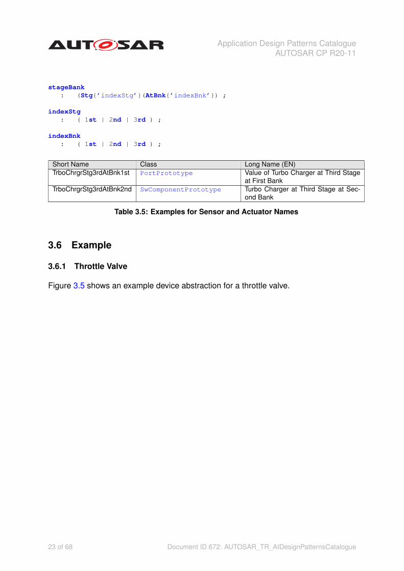
In grammar 3.5 a pattern is described how to refine ’anyNamePart’ as defined in gram-mar 3.3 in case of a system with several banks and stages. In Table 3.5 correspondingname examples are shown using this grammar part.
Listing 3.5: Name Pattern for Signals in Device Abstraction in Case of a System withSeveral Banksgrammar PSnsrActrStgBnkShortNames;
22 of 68 Document ID 672: AUTOSAR_TR_AIDesignPatternsCatalogue
Application Design Patterns CatalogueAUTOSAR CP R20-11
stageBank: (Stg{’indexStg’}(AtBnk{’indexBnk’}) ;
indexStg: ( 1st | 2nd | 3rd ) ;
indexBnk: ( 1st | 2nd | 3rd ) ;
Short Name Class Long Name (EN)TrboChrgrStg3rdAtBnk1st PortPrototype Value of Turbo Charger at Third Stage
at First BankTrboChrgrStg3rdAtBnk2nd SwComponentPrototype Turbo Charger at Third Stage at Sec-
ond Bank
Table 3.5: Examples for Sensor and Actuator Names
3.6 Example
3.6.1 Throttle Valve
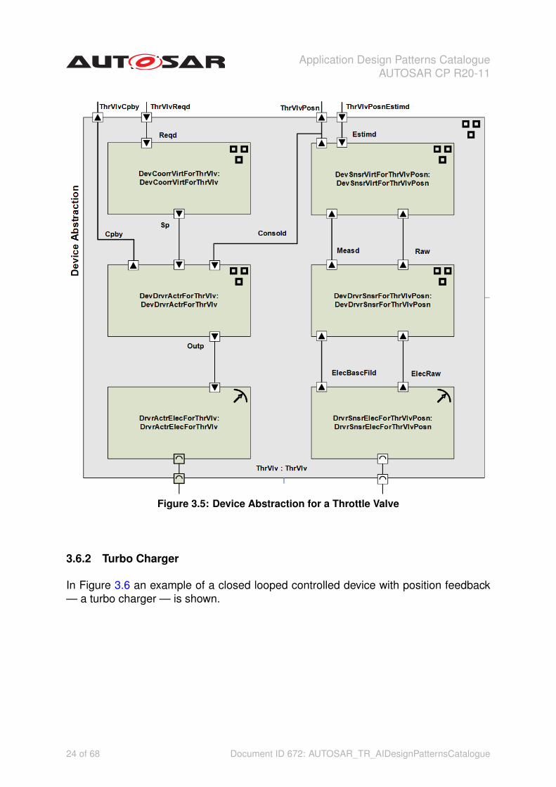
Figure 3.5 shows an example device abstraction for a throttle valve.
23 of 68 Document ID 672: AUTOSAR_TR_AIDesignPatternsCatalogue
Application Design Patterns CatalogueAUTOSAR CP R20-11
Figure 3.5: Device Abstraction for a Throttle Valve
3.6.2 Turbo Charger
In Figure 3.6 an example of a closed looped controlled device with position feedback— a turbo charger — is shown.
24 of 68 Document ID 672: AUTOSAR_TR_AIDesignPatternsCatalogue

Application Design Patterns CatalogueAUTOSAR CP R20-11
Figure 3.6: Device Abstraction for a Turbo Charger
Hint: In most cases it is not recommended to use company names in model names(like "AcmeXYZ" used in the Figures). Company names etc. are only used in theexamples to show the difference between type and prototype and what is the reasonfor the difference. For general rules and recommendations how to deal with variantsin models, as for example expressed by the company names in the examples, pleaserefer to the modeling guides and templates.
3.6.3 Turbo Charger with Stages and Banks
In Figure 3.7 a project system configuration for turbo charger with several stages andbanks is shown.
25 of 68 Document ID 672: AUTOSAR_TR_AIDesignPatternsCatalogue

Application Design Patterns CatalogueAUTOSAR CP R20-11
Figure 3.7: Device Abstraction for a Turbo Charger with Banks and Stages
3.6.4 Actuator without Feedback Loop
In Figure 3.8 an open loop controlled actuator is shown that calculates the consolidatedvalue using the setpoint input as input. As described before there are alternativeshow to calculate the consolidated value. No estimated value (Estimd) is used in thisexample.
26 of 68 Document ID 672: AUTOSAR_TR_AIDesignPatternsCatalogue

Application Design Patterns CatalogueAUTOSAR CP R20-11
Figure 3.8: Example Actuator without Feedback Loop (Setpoint Alternative)
3.6.5 Standard Sensor
In Figure 3.9 a design pattern of blueprint components for a standard sensor is shown.
27 of 68 Document ID 672: AUTOSAR_TR_AIDesignPatternsCatalogue

Application Design Patterns CatalogueAUTOSAR CP R20-11
Figure 3.9: Device Abstraction for Standard Sensor
3.6.6 Standard Sensor for Environment Temperature
In Figure 3.10 a standard sensor for environment temperature is shown.
28 of 68 Document ID 672: AUTOSAR_TR_AIDesignPatternsCatalogue

Application Design Patterns CatalogueAUTOSAR CP R20-11
Figure 3.10: Device Abstraction for a Sensor measuring the Environment Temperature
3.6.7 Distributing Device Abstraction
In Figure 3.12 the ECU view derived from the VFB view of a temperature sensor asshown in Figure 3.11 is shown. Finally it is shown that it is possible to also deploy thedifferent SW-C to different ECUs. Of course timing constraints have to be consideredbefore distributing components to different ECUs.
29 of 68 Document ID 672: AUTOSAR_TR_AIDesignPatternsCatalogue

Application Design Patterns CatalogueAUTOSAR CP R20-11
Figure 3.11: VFB View of Temperature Sensor Example
Figure 3.12: ECU Views after Distribution of SW-Cs of Temperature Sensor to two ECUs
30 of 68 Document ID 672: AUTOSAR_TR_AIDesignPatternsCatalogue

Application Design Patterns CatalogueAUTOSAR CP R20-11
3.7 Sample Code and Model
In Listing 3.6 a blueprint for the components used in the Sensor/Actuator pattern isprovided. The blueprint code is not complete but just gives an idea how it is realized.The composition component is not shown.
Please note that the AUTOSAR meta model requests that a sensor actuator componenttype references a corresponding sensor or actuator, resp., using a HwDescriptio-nEntity, [12]. In this case a HwElement is needed to be used. Since there is astandardized HwCategory for sensors and actuators also a HwType is defined that isreferenced by the HwElement.
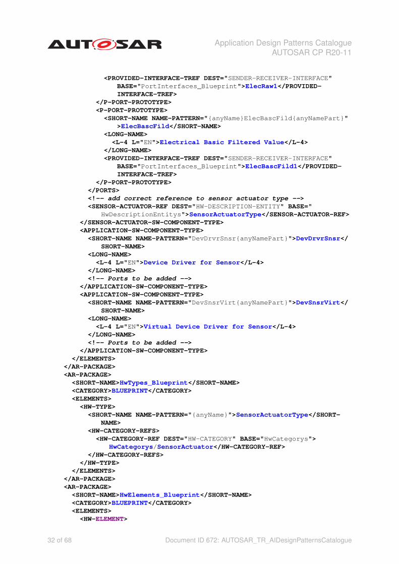
Listing 3.6: Sensor/Actuator Pattern<AR-PACKAGE>
<SHORT-NAME>SwComponentTypes_Blueprint</SHORT-NAME><CATEGORY>BLUEPRINT</CATEGORY><REFERENCE-BASES>
<REFERENCE-BASE><SHORT-LABEL NAME-PATTERN="{anyName}">HwDescriptionEntitys</SHORT
-LABEL><IS-DEFAULT>false</IS-DEFAULT><IS-GLOBAL>false</IS-GLOBAL><BASE-IS-THIS-PACKAGE>false</BASE-IS-THIS-PACKAGE><PACKAGE-REF DEST="AR-PACKAGE"><?xm-replace_text {PACKAGE-REF}?><
/PACKAGE-REF><!--addpackage path -->
</REFERENCE-BASE><REFERENCE-BASE>
<SHORT-LABEL NAME-PATTERN="{anyName}">PortInterfaces_Blueprint</SHORT-LABEL>
<IS-DEFAULT>false</IS-DEFAULT><IS-GLOBAL>false</IS-GLOBAL><BASE-IS-THIS-PACKAGE>false</BASE-IS-THIS-PACKAGE><PACKAGE-REF DEST="AR-PACKAGE"><?xm-replace_text {PACKAGE-REF}?><
/PACKAGE-REF><!--addpackage path -->
</REFERENCE-BASE></REFERENCE-BASES><ELEMENTS>
<SENSOR-ACTUATOR-SW-COMPONENT-TYPE><SHORT-NAME NAME-PATTERN="{anyName}DrvrSnsrElec{anyNamePart}">
DrvrSnsrElec</SHORT-NAME><LONG-NAME>
<L-4 L="EN">Driver for Electrical Signals of Sensor</L-4></LONG-NAME><INTRODUCTION><!-- optional: add documentation --></INTRODUCTION><PORTS>
<P-PORT-PROTOTYPE><SHORT-NAME NAME-PATTERN="{anyName}ElecRaw{anyNamePart}">
ElecRaw</SHORT-NAME><LONG-NAME>
<L-4 L="EN">Electrical Raw Value</L-4></LONG-NAME>
31 of 68 Document ID 672: AUTOSAR_TR_AIDesignPatternsCatalogue
Application Design Patterns CatalogueAUTOSAR CP R20-11
<PROVIDED-INTERFACE-TREF DEST="SENDER-RECEIVER-INTERFACE"BASE="PortInterfaces_Blueprint">ElecRaw1</PROVIDED-INTERFACE-TREF>
</P-PORT-PROTOTYPE><P-PORT-PROTOTYPE>
<SHORT-NAME NAME-PATTERN="{anyName}ElecBascFild{anyNamePart}">ElecBascFild</SHORT-NAME>
<LONG-NAME><L-4 L="EN">Electrical Basic Filtered Value</L-4>
</LONG-NAME><PROVIDED-INTERFACE-TREF DEST="SENDER-RECEIVER-INTERFACE"
BASE="PortInterfaces_Blueprint">ElecBascFild1</PROVIDED-INTERFACE-TREF>
</P-PORT-PROTOTYPE></PORTS><!-- add correct reference to sensor actuator type --><SENSOR-ACTUATOR-REF DEST="HW-DESCRIPTION-ENTITY" BASE="
HwDescriptionEntitys">SensorActuatorType</SENSOR-ACTUATOR-REF></SENSOR-ACTUATOR-SW-COMPONENT-TYPE><APPLICATION-SW-COMPONENT-TYPE>
<SHORT-NAME NAME-PATTERN="DevDrvrSnsr{anyNamePart}">DevDrvrSnsr</SHORT-NAME>
<LONG-NAME><L-4 L="EN">Device Driver for Sensor</L-4>
</LONG-NAME><!-- Ports to be added -->
</APPLICATION-SW-COMPONENT-TYPE><APPLICATION-SW-COMPONENT-TYPE>
<SHORT-NAME NAME-PATTERN="DevSnsrVirt{anyNamePart}">DevSnsrVirt</SHORT-NAME>
<LONG-NAME><L-4 L="EN">Virtual Device Driver for Sensor</L-4>
</LONG-NAME><!-- Ports to be added -->
</APPLICATION-SW-COMPONENT-TYPE></ELEMENTS>
</AR-PACKAGE><AR-PACKAGE>
<SHORT-NAME>HwTypes_Blueprint</SHORT-NAME><CATEGORY>BLUEPRINT</CATEGORY><ELEMENTS>
<HW-TYPE><SHORT-NAME NAME-PATTERN="{anyName}">SensorActuatorType</SHORT-
NAME><HW-CATEGORY-REFS>
<HW-CATEGORY-REF DEST="HW-CATEGORY" BASE="HwCategorys">HwCategorys/SensorActuator</HW-CATEGORY-REF>
</HW-CATEGORY-REFS></HW-TYPE>
</ELEMENTS></AR-PACKAGE><AR-PACKAGE>
<SHORT-NAME>HwElements_Blueprint</SHORT-NAME><CATEGORY>BLUEPRINT</CATEGORY><ELEMENTS>
<HW-ELEMENT>
32 of 68 Document ID 672: AUTOSAR_TR_AIDesignPatternsCatalogue
Application Design Patterns CatalogueAUTOSAR CP R20-11
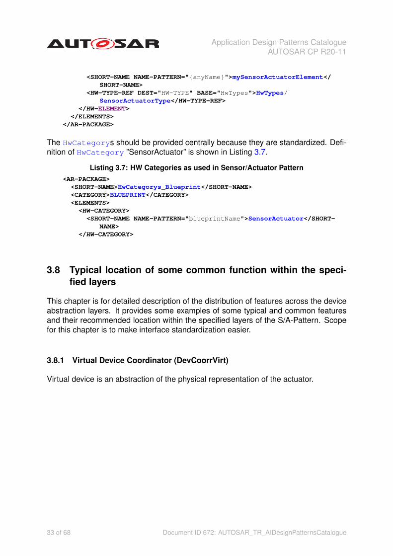
<SHORT-NAME NAME-PATTERN="{anyName}">mySensorActuatorElement</SHORT-NAME>
<HW-TYPE-REF DEST="HW-TYPE" BASE="HwTypes">HwTypes/SensorActuatorType</HW-TYPE-REF>
</HW-ELEMENT></ELEMENTS>
</AR-PACKAGE>
The HwCategorys should be provided centrally because they are standardized. Defi-nition of HwCategory ”SensorActuator” is shown in Listing 3.7.
Listing 3.7: HW Categories as used in Sensor/Actuator Pattern<AR-PACKAGE>
<SHORT-NAME>HwCategorys_Blueprint</SHORT-NAME><CATEGORY>BLUEPRINT</CATEGORY><ELEMENTS>
<HW-CATEGORY><SHORT-NAME NAME-PATTERN="blueprintName">SensorActuator</SHORT-
NAME></HW-CATEGORY>
3.8 Typical location of some common function within the speci-fied layers
This chapter is for detailed description of the distribution of features across the deviceabstraction layers. It provides some examples of some typical and common featuresand their recommended location within the specified layers of the S/A-Pattern. Scopefor this chapter is to make interface standardization easier.
3.8.1 Virtual Device Coordinator (DevCoorrVirt)
Virtual device is an abstraction of the physical representation of the actuator.
33 of 68 Document ID 672: AUTOSAR_TR_AIDesignPatternsCatalogue

Application Design Patterns CatalogueAUTOSAR CP R20-11
Figure 3.13: Typical functions in layer DevCoorrVirt
3.8.1.1 Conversion and linearization of physical requested value
Typically there is a delta between the mechanical endstops and the position where thephysical effects are influenced due to the movement of the actuator. This gap could becompensated via offset compensation algorithm of the position sensor or via lineariza-tion of the requested setpoint value. The transfer function is used to compensate theactuator HW design/physics.
3.8.1.2 DCM service / Diagnostic tester interface for basic function test
The DCM service interface is typically used as a tester interface and can overwrite therequested value to perform a basic function test of the actuator.
34 of 68 Document ID 672: AUTOSAR_TR_AIDesignPatternsCatalogue
Application Design Patterns CatalogueAUTOSAR CP R20-11
3.8.1.3 Cleaning / Ice breaking
Overwrite/Ignore the requested value, in order to prepare the actuator for proper actu-ation. The function switches between two different setpoint values for a specific timeto either
1. condition the actuator for offset learning
2. clean particles/compounds from actuator
3. break up from ice
3.8.1.4 Dither of setpoint
Continous overlayed/modulated signal on setpoint value to overcome static friction ofactuator.
3.8.1.5 Release function of setpoint
The release function is manipulating the requested setpoint value. This could beneeded in case of a blocked actuator, i.e. the actuator got stuck at its position.
3.8.1.6 Coordination of activation and deactivation of the actuator
Activation: The actuator shall be activated as soon as actuation is requested.Deactivation: To ensure safe operation, the actuator shall be shut off under certainconditions (incl. monitoring e.g. open hood) and shall be shut off to fail safe beforevoltage supply is switched off.
35 of 68 Document ID 672: AUTOSAR_TR_AIDesignPatternsCatalogue

Application Design Patterns CatalogueAUTOSAR CP R20-11
3.8.2 Actuator Device Driver (DevDrvrActr)
Figure 3.14: Typical functions in layer DevDrvrActr
3.8.2.1 Dither of output value
Continous overlayed/modulated signal on output value to overcome static friction ofactuator.
3.8.2.2 Release function of output value
The release function is manipulating the output value. This could be needed in case ofa blocked actuator, i.e. the actuator got stuck at its position.
36 of 68 Document ID 672: AUTOSAR_TR_AIDesignPatternsCatalogue

Application Design Patterns CatalogueAUTOSAR CP R20-11
3.8.2.3 Limitation
3.8.2.3.1 Static limitation
The output value is limited to protect the actuator from any mechanical or thermaldamage at a static position. It is a static limitation of the output value.Example: Limitation of dutycycle at the mechanical endstops, e.g. to avoid overheating.
3.8.2.3.2 Dynamic limitation for overheating protection
Effective current monitoring + housing/motor temperature monitoring is used as over-heating protection. To protect the actuator of overheating, the energy input to theactuator or the temperature inside the actuator is observed. It is a dynamic limitationof the output value.Hint: The temperature information could also come as a consolidated value from anabstracted sensor SW component.
3.8.2.4 Feed forward controller
The Feed Forward Controller compensatex the influcence of the known disturbancesin the controlled system. It calculates the pre-controlled output value.
3.8.2.5 Closed loop controller
The Closed Loop Controller uses feedback to control output of a dynamic system, i.e.the output value is adapted according to the consolidated value.
3.8.2.6 Set point limitation
Set point limitation given by plant used as closed loop controller input.
3.8.2.7 Set point gradient limitation
Protection of the actuator by limiting the set point gradient, e.g. in position close to theendstops.
3.8.2.8 Control deviation monitoring
Monitoring of the permanent deviation between setpoint and consolidated value.
37 of 68 Document ID 672: AUTOSAR_TR_AIDesignPatternsCatalogue

Application Design Patterns CatalogueAUTOSAR CP R20-11
3.8.2.9 Capability
Providing a Capability is a way of summarizing all active limitations on an actuator.The Capability is related to the requested set point, providing the dynamic boundariesof possible usage.For example, an electric machine actuator SW composition will report its capability tothe coordinator functionality in the application software. If the capability is reduced, thecoordinator functionality in the application software may use this capability informationto redistribute the requested set points differently between the actuators of the systemto obtain the overall system control objective.
Generic Sig-nal Name
Long Name Pattern ofConcrete Sensor/Actua-tor Signal (EN)
Generic Long Name ofSignal (EN)
AUTOSAR Definition
Cpby Capability {anyLong-NamePart}
Capability Provides the dynamic instant ca-pability typically based on outputlimitation but could also containthe limitation on rate of changeof the consolidated value. It isexpressed as percentage.
Table 3.6: Signal Names and Semantics of function Capability
This following section presents examples of capability.The capability can be described as the temporary dynamic bounds of actuation. Thesebounds could depend on current working point of operation or some consolidatedvalue. The capability is provided as percentage of maximum defined actuator limi-tations.For example, if the capability is provided as neutral (see figure 3.15), the capability isset to 100%. Consequently, neutral capability does not reflect the current effectivenessof the actuator.
Figure 3.15: Example for providing neutral Capability information
In another example (see figure 3.16), the capability is provided as a function of the setpoint and output limitations. The dynamic set point and output limitations may then alsobe a function of the consolidated value.
38 of 68 Document ID 672: AUTOSAR_TR_AIDesignPatternsCatalogue

Application Design Patterns CatalogueAUTOSAR CP R20-11
Figure 3.16: Example for simple Capability calculation
3.8.3 Electrical Actuator Driver (DrvrActrElec)
Figure 3.17: Typical functions in layer DrvrActrElec
39 of 68 Document ID 672: AUTOSAR_TR_AIDesignPatternsCatalogue

Application Design Patterns CatalogueAUTOSAR CP R20-11
3.8.3.1 Power stage monitoring
An ECU might contain various power stages for driving different electrical loads.Common electrical faults at power stages are Short Circuit to Battery (SCB), ShortCircuit to Ground (SCG), and Open Load (OL). These faults can occur during eitheron-state or off-state of the power stage output.
3.8.4 Virtual Device Driver (DevSnsrVirt)
Figure 3.18: Typical functions in layer DevSnsrVirt
3.8.4.1 Substitution
The function switches between the measured and a replacement value. The replace-ment value could be the estimated value.Example: The switching can happen based on:
1. Sensor diagnostic information
40 of 68 Document ID 672: AUTOSAR_TR_AIDesignPatternsCatalogue

Application Design Patterns CatalogueAUTOSAR CP R20-11
2. Sensor signal quality
3. Sensor availabilty
3.8.4.2 Inertia compensation
The function provides a predicted sensor value (forecast) to compensate the inertia ofthe sensor.Examples: thermal inertia, mechanical inertia
3.8.4.3 Signal qualifier evaluation
The quality of the consolidated value is provided by that function. It is determined bychecking consolidated value and all sensor related diagnosis information.
3.8.4.4 DCM service / Diagnostic tester interface for basic function test
The DCM service interface is typically used to overwrite and stimulate the consolidatedsensor value.
3.8.4.5 Plausibilization
3.8.4.5.1 Continous plausibilization
The measured value is checked continously against another redundant sensor infor-mation. This redundant sensor information can be provided by any other sensor or bythe estimated value.Example: Offset diagnosis, in case difference (measured value vs. redundant value)exceeds certain threshold, e.g. tolerance threshold.
3.8.4.5.2 Conditional plausibilization
The measured value is checked at specific points in time (e.g. once in a driving cycleor at specific driving modes) against another redundant sensor information. This re-dundant sensor information can be provided by any other sensor or by the estimatedvalue.Hint: The conditional plausibilization can be used to compensate or just identify sensorindividual tolerances.
41 of 68 Document ID 672: AUTOSAR_TR_AIDesignPatternsCatalogue

Application Design Patterns CatalogueAUTOSAR CP R20-11
3.8.5 Sensor Device Driver (DevDrvrSnsr)
Figure 3.19: Typical functions in layer DevDrvrSnsr
3.8.5.1 High level filtering
This function block contains every kind of filter which might lead to a significant phaseshift of the sensor value in order to provide a physical sensor value, fitting to require-ments from user functions (regarding timing, accuracy).Hint: Therefore a good trade-off between phase shift and accuracy has to be found.
3.8.5.2 Offset adaption
The result of conditional plausibilization can be used to do an offset adaption of mea-sured value to compensate individual tolerances of the sensor. The determined offsetinformation is used to adapt the sensor signal to show values closer to the actual phys-ical signal.Hint: The conditional plausibilization can be used to compensate or just identify sensorindividual tolerances.
42 of 68 Document ID 672: AUTOSAR_TR_AIDesignPatternsCatalogue

Application Design Patterns CatalogueAUTOSAR CP R20-11
3.8.5.3 Zero point adaption
The zero point adaption is used to adjust the transfer function in the conversion to thephysical zero point.Hint: The adaption of this zero point is done within the conversion block.Example 1: Sensors measuring relative values (differential pressure) shall show 0 ifthere is equalized pressure.Example 2: The sensor value is adapted to the mechanical endstop position of anclosed loop operated actuator.
3.8.5.4 Drift detection
Sensor values are monitored throughout the driving cycle and used to derive a sensordeviation compared to the first and last learned value.Hint: Can be used for offset adaption, to improve sensor information or it can be usedfor diagnosis purpose only.
3.8.5.5 Conversion
The electrical signal is converted into physical representation by transfer function. Incase of nonlinear signal, linearization will be part of transfer function as well.
3.8.5.6 Physical signal gradient calculation
In order to get information about the current dynamic of the sensed system, a gradientis calculated based on current and previous sensor information.
3.8.5.7 Physical signal gradient check
The gradient of the physical signal is checked against a maximum. For certain sensorsa maximum gradient should not be exceeded. In case the sensor shows a highergradient, it could be indicated as defect.
3.8.5.8 Stuck check diagnosis
Identify a "frozen" sensor information, in case the sensor signal does not change. Apermanent "frozen" sensor information could be indicated as a defect.
43 of 68 Document ID 672: AUTOSAR_TR_AIDesignPatternsCatalogue

Application Design Patterns CatalogueAUTOSAR CP R20-11
3.8.5.9 Physical signal range check
Comparison of physical sensor signal against minimum and maximum thresholds forcontinuous diagnosis of physical limits.
3.8.6 Electrical Sensor Driver (DrvrSnsrElec)
Figure 3.20: Typical functions in layer DrvrSnsrElec
3.8.6.1 Basic filter
A basic filter is needed to mitigate electric noise. The timing behavior shall not give anysignificant phase shift to signal.Example: The definition of a significant phase shift is that it does not have any impacton the physical behaviour of the system. For signals influenced by the combustion thephase shift should not exceed the time given by a 360deg camshaft rotation.Hint: Possible filter types for this use case could be FIR (finite impulse response) filteror PLL (phase locked loop).Reason: The DevDrvrSnsr transfers electrical value to physical value. In case the sig-
44 of 68 Document ID 672: AUTOSAR_TR_AIDesignPatternsCatalogue
Application Design Patterns CatalogueAUTOSAR CP R20-11
nal already has a phase shift, the timing within the upper layers cannot be compensatedanymore.
3.8.6.2 Voltage compensation
Required for sensors with power supply from outside ECU. The seperate power supplycreates a potential difference in reference voltage which needs to be compensated inSW.Hint: This functionality can be realized in hardware alternatively.
3.8.6.3 Electrical diagnosis
It is needed to diagnose electrical faults on the sensor.Examples: Short Circuit to Battery (SCB), Short Circuit to Ground (SCG), Open Circuit,Loose Contact.
3.9 Known Issues
Sensor abstraction of sensors with typical digital interfaces (e.g. SENT, FAS) or whichare connected via bus (e.g. CAN, LIN) is part of this pattern as well. Description ofrequired extensions is in progress.
3.10 FAQ
• Why is the estimated value in Example "Actuator without Feedback Loop (Set-point Alternative)" not used?An estimated value does not exist for every sensor. So there is no need for itto be used. In this example, the consolidated value is calculated based on thesetpoint.
• Is there a signal quality considered in the pattern?The topic "signal qualifier" is not yet considered. At the moment (R19-11) thereis no activity known for standardizing such a signal quality.
• How are the names for the layers derived (e.g. DevCoorrVirt)? Can they bechanged?The AUTOSAR abbreviations are given by strict rules [3]. Even the concatena-tion of the abbreviations is defined. The names should not be changed due tobackward compatibility reasons.
45 of 68 Document ID 672: AUTOSAR_TR_AIDesignPatternsCatalogue

Application Design Patterns CatalogueAUTOSAR CP R20-11
3.11 Known Uses
None.
3.12 Related Patterns
Pattern DescriptionArbitration Pattern(see Chapter 4)
The sensor/actuator pattern is typically combined with the arbitration patternto allow several set point requesters, several providers of consolidated valuesor several providers of estimated values. This is, arbitration is not done withinthe sensor/actuator pattern but outside the device abstraction.
Table 3.7: Related Patterns
3.13 Anti-Patterns One Should be Aware of
None.
3.14 Further Readings
More information could be found in [12] and [13].
46 of 68 Document ID 672: AUTOSAR_TR_AIDesignPatternsCatalogue

Application Design Patterns CatalogueAUTOSAR CP R20-11
4 Arbitration between several requesters or providers
Classification Design Pattern
4.1 Problem
Arbitration between several different providers or requesters.
4.2 Applicability
The number of requesters or providers, resp., has to be known at pre-compile time.The number of requesters or providers, resp., has to be known at implementation orgeneration time of the arbiter component.
This pattern can be applied in the context of Sensor/Actuator Design Pattern, e.g.for modeling several setpoint requesters, several providers of consolidated values orseveral providers of estimated values.
4.3 Solution
A new component for managing all requests from different requesters or providers,resp., is introduced. In Figure 4.1 the overall pattern for requesters is shown in casesender receiver interfaces are used. In Figure 4.2 the overall pattern for providers isshown in case sender receiver interfaces are used.
When using sender/receiver interfaces the arbitration component, also called ”arbiter”,needs to have unique names for the different requests or providers. This is realized bydifferent request or provide ports, one per requester or provider, resp. The port inter-face or at least the application data type is typically the same for all of these requestersor providers, resp., and the resulting request or arbitrated value.
47 of 68 Document ID 672: AUTOSAR_TR_AIDesignPatternsCatalogue

Application Design Patterns CatalogueAUTOSAR CP R20-11
Figure 4.1: Pattern ”Arbitration between Several Requesters”
48 of 68 Document ID 672: AUTOSAR_TR_AIDesignPatternsCatalogue

Application Design Patterns CatalogueAUTOSAR CP R20-11
Figure 4.2: Pattern ”Arbitration between Several Providers”
[TR_AIDPC_00006] Arbitration of requesters dAn arbitration component is intro-duced to support several requesters of the same action but not necessarily of the samevalue.c(RS_MAIN_00060)
[TR_AIDPC_00007] Arbitration of providers dAn arbitration component is introducedto support several providers of the same signal.c(RS_MAIN_00060)
49 of 68 Document ID 672: AUTOSAR_TR_AIDesignPatternsCatalogue
Application Design Patterns CatalogueAUTOSAR CP R20-11
4.4 Examples
4.4.1 Several Setpoint Requesters
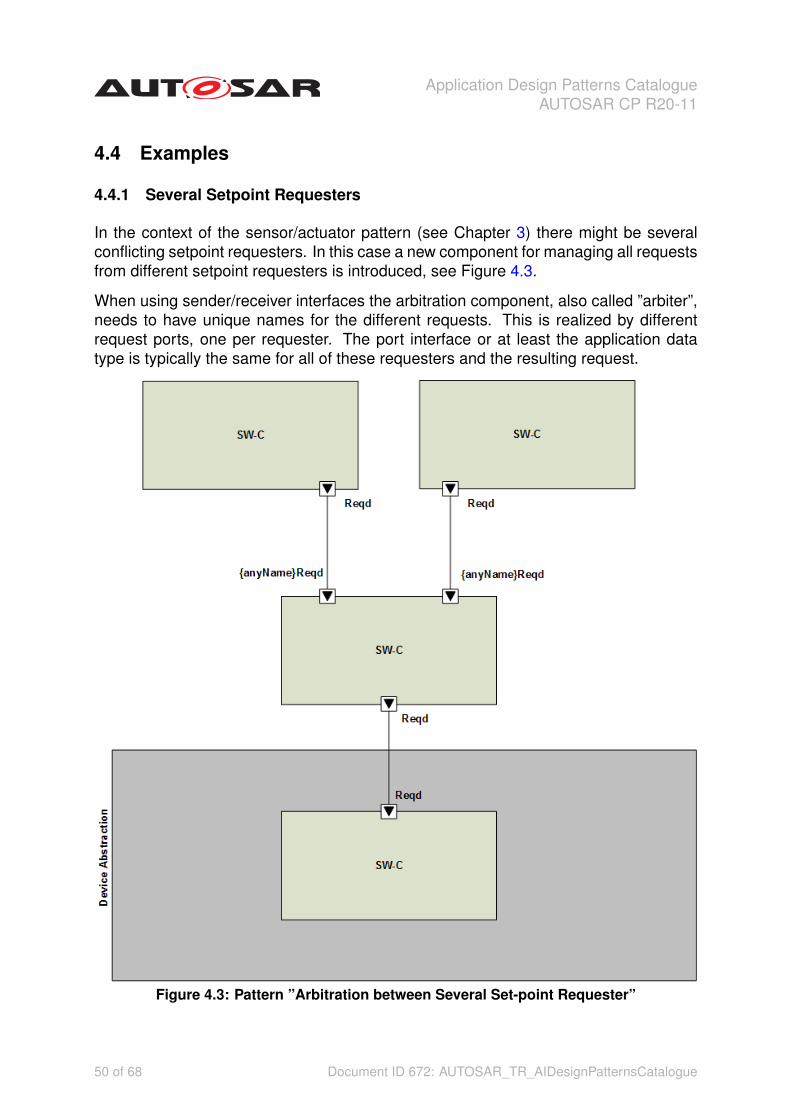
In the context of the sensor/actuator pattern (see Chapter 3) there might be severalconflicting setpoint requesters. In this case a new component for managing all requestsfrom different setpoint requesters is introduced, see Figure 4.3.
When using sender/receiver interfaces the arbitration component, also called ”arbiter”,needs to have unique names for the different requests. This is realized by differentrequest ports, one per requester. The port interface or at least the application datatype is typically the same for all of these requesters and the resulting request.
Figure 4.3: Pattern ”Arbitration between Several Set-point Requester”
50 of 68 Document ID 672: AUTOSAR_TR_AIDesignPatternsCatalogue

Application Design Patterns CatalogueAUTOSAR CP R20-11
In grammar 4.1 it is described how the provide ports of the requesters as well asthe request ports of the arbiter should be named: they all have the suffix ”Reqd” for”Required”. So terms like ”desired”, ”wished” etc. should not be used to avoid that toomany terms with similar meanings are used without being able to distinguish them.
Listing 4.1: Name Pattern for Ports of Arbiter and Requestersgrammar PArbSpReqPortNames;
portName: ({anyName}){’Reqd’} ;
anyName: (’keyword’)* ;
Figure 4.4 shows the pattern in the context of the RTE. The Device Abstraction isdesigned as one large composition but this is not requested by the Sensor/Actuatorpattern.
Figure 4.4: Arbitration between Several Requesters via RTE
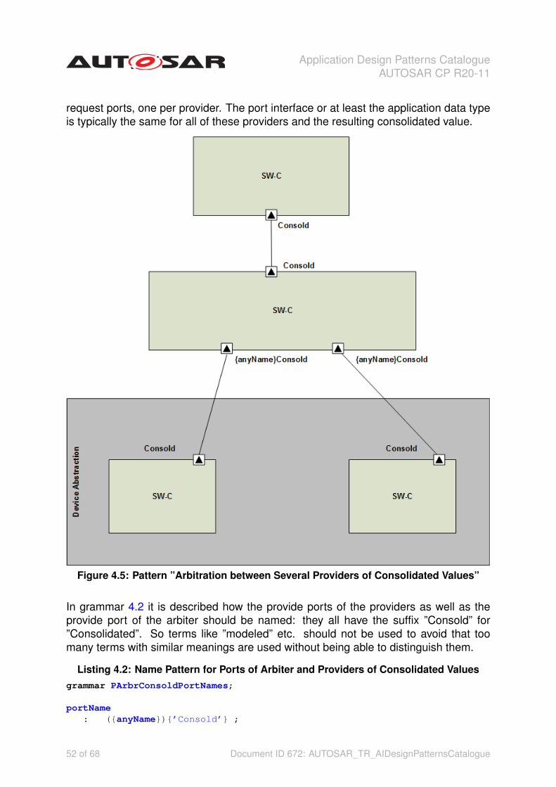
4.4.2 Several Providers of Consolidated Values
In the context of the sensor/actuator pattern (3) there might be several sensors provid-ing the same physical information. This is, there are several component all providing aconsolidated values for a specific physical signal.
A new component for managing all consolidated values from different providers is in-troduced, see Figure 4.5.
When using sender/receiver interfaces the arbitration component, also called ”arbiter”,needs to have unique names for the different providers. This is realized by different
51 of 68 Document ID 672: AUTOSAR_TR_AIDesignPatternsCatalogue
Application Design Patterns CatalogueAUTOSAR CP R20-11
request ports, one per provider. The port interface or at least the application data typeis typically the same for all of these providers and the resulting consolidated value.
Figure 4.5: Pattern ”Arbitration between Several Providers of Consolidated Values”
In grammar 4.2 it is described how the provide ports of the providers as well as theprovide port of the arbiter should be named: they all have the suffix ”Consold” for”Consolidated”. So terms like ”modeled” etc. should not be used to avoid that toomany terms with similar meanings are used without being able to distinguish them.
Listing 4.2: Name Pattern for Ports of Arbiter and Providers of Consolidated Valuesgrammar PArbrConsoldPortNames;
portName: ({anyName}){’Consold’} ;
52 of 68 Document ID 672: AUTOSAR_TR_AIDesignPatternsCatalogue

Application Design Patterns CatalogueAUTOSAR CP R20-11
anyName: (’keyword’)* ;
4.4.3 Several Providers of Estimated Values
In the context of the sensor/actuator pattern (3) there might be several model for calcu-lating an estimation value. However, in the end only one of the estimated values shouldbe input to the sensor/actuator pattern. Therefore, a new component for managing allestimated values from different providers is introduced, see Figure 4.6.
When using sender/receiver interfaces the arbitration component, also called ”arbiter”,needs to have unique names for the different providers. This is realized by differentrequest ports, one per provider. The port interface or at least the application data typeis typically the same for all of these providers and the resulting estimated value.
53 of 68 Document ID 672: AUTOSAR_TR_AIDesignPatternsCatalogue

Application Design Patterns CatalogueAUTOSAR CP R20-11
Figure 4.6: Pattern ”Arbitration between Several Providers of Estimated Values”
In grammar 4.3 it is described how the provide ports of the providers as well as theprovide port of the arbiter should be named: they all have the suffix ”Estimd” for ”Esti-mated”. So terms like ”modeled” etc. should not be used to avoid that too many termswith similar meanings are used without being able to distinguish them.
Listing 4.3: Name Pattern for Ports of Arbiter and Providers of Estimated Valuesgrammar PArbEstimdPortNames;
portName: ({anyName}){’Estimd’} ;
anyName: (’keyword’)* ;
54 of 68 Document ID 672: AUTOSAR_TR_AIDesignPatternsCatalogue

Application Design Patterns CatalogueAUTOSAR CP R20-11
4.5 Sample Code and Model
None.
4.6 Known Uses
This pattern is typically applied in the context of usage of the Sensor/Actuator DesignPattern.
4.7 Related Patterns
Pattern DescriptionSensor Actua-tor Pattern (seeChapter 3)
The sensor/actuator pattern is typically combined with the arbitration patternto allow several set point requesters, several providers of consolidated valuesor several providers of estimated values. This is, arbitration is not done withinthe sensor/actuator pattern but outside the device abstraction.
Table 4.1: Related Patterns
55 of 68 Document ID 672: AUTOSAR_TR_AIDesignPatternsCatalogue

Application Design Patterns CatalogueAUTOSAR CP R20-11
5 Signal Quality States
Classification Design Pattern
5.1 Problem
For each (sensor) signal / value the corresponding quality information is also neededto be transferred along with the signal value.
The main intention is to have a common understanding of signal quality and to stan-dardize the states a signal quality can have.
5.2 Applicability
This scope of this pattern is the definition of signal quality states (e.g. the content ofthe signal quality interfaces). The implementation of such a signal quality interface isnot in scope of this document as there are several implementations possible.
The signal quality states defined in this document are a minimum set of recommendedsignal quality states.
5.3 Solution
Signal quality State of related sig-nal value
Meaning
UNDEFINED Undefined value No information about quality at all. It means that signalquality is not defined and the signal value is not initialized/ calculated yet or is not calculated any more (e.g. desireddeactivation of functionality)
VALID Valid value Trustworthy value from main signal sourceREPLACEMENT Replacement value
with reduced valid-ity
Modelled value or even defined constant value (mostlydone by calibration). There is no information about thevalidity of the signal value, i.e. there is no additional infor-mation how "‘good"’ the replacement value represents theoriginal value.
FROZEN Frozen value Frozen value. A valid value must have been calculatedbefore. There is no information about since how long thesignal value is frozen
INVALID Invalid value Value is not trustworthy and must not be used
Table 5.1: Signal Quality States
Additional information to table 5.1:
• Transitions from UNDEFINED to FROZEN is not allowed, because the previousvalue was not a valid value
56 of 68 Document ID 672: AUTOSAR_TR_AIDesignPatternsCatalogue

Application Design Patterns CatalogueAUTOSAR CP R20-11
• UNDEFINED level is default value of signal quality interfaces
57 of 68 Document ID 672: AUTOSAR_TR_AIDesignPatternsCatalogue

Application Design Patterns CatalogueAUTOSAR CP R20-11
A Change History
A.1 Change History AUTOSAR R4.3.0
A.1.1 Added Constraints in R4.3.0
No constraints were added in this release.
A.1.2 Changed Constraints in R4.3.0
No constraints were changed in this release.
A.1.3 Deleted Constraints in R4.3.0
No constraints were deleted in this release.
A.1.4 Added Specification Items in R4.3.0
Number Heading[TR_AIDPC_00006] Arbitration of requesters[TR_AIDPC_00007] Arbitration of providers
Table A.1: Added Specification Items in 4.3.0
A.1.5 Changed Specification Items in R4.3.0
No specification items were changed in this release.
A.1.6 Deleted Specification Items in R4.3.0
No specification items were deleted in this release.
A.2 Change History AUTOSAR R4.2.2
A.2.1 Added Constraints in R4.2.2
No constraints were added in this release.
58 of 68 Document ID 672: AUTOSAR_TR_AIDesignPatternsCatalogue

Application Design Patterns CatalogueAUTOSAR CP R20-11
A.2.2 Changed Constraints in R4.2.2
No constraints were changed in this release.
A.2.3 Deleted Constraints in R4.2.2
No constraints were deleted in this release.
A.2.4 Added Specification Items in R4.2.2
Number Heading[TR_AIDPC_00001] Access to Hardware by PSnsrAct[TR_AIDPC_00002] Collaboration supported by PSnsrAct[TR_AIDPC_00003] Deployment/Relocation supported by PSnsrAct[TR_AIDPC_00004] Layers of PSnsrAct[TR_AIDPC_00005] Naming within PSnsrAct
Table A.2: Added Specification Items in 4.2.2
A.2.5 Changed Specification Items in R4.2.2
No specification items were changed in this release.
A.2.6 Deleted Specification Items in R4.2.2
No specification items were deleted in this release.
A.3 Change History AUTOSAR R4.2.1
A.3.1 Added Constraints in R4.2.1
No constraints were added in this initial release.
A.3.2 Added Specification Items in R4.2.1
No specification items were added in this initial release.
59 of 68 Document ID 672: AUTOSAR_TR_AIDesignPatternsCatalogue

Application Design Patterns CatalogueAUTOSAR CP R20-11
B Mentioned Class Tables
For the sake of completeness, this chapter contains a set of class tables representingmeta-classes mentioned in the context of this document but which are not containeddirectly in the scope of describing specific meta-model semantics.
Class ApplicationSwComponentType
Package M2::AUTOSARTemplates::SWComponentTemplate::Components
Note The ApplicationSwComponentType is used to represent the application software.
Tags:atp.recommendedPackage=SwComponentTypes
Base ARElement , ARObject , AtomicSwComponentType, AtpBlueprint , AtpBlueprintable, AtpClassifier , AtpType, CollectableElement , Identifiable, MultilanguageReferrable, PackageableElement , Referrable, SwComponentType
Attribute Type Mult. Kind Note
– – – – –
Table B.1: ApplicationSwComponentType
Class CompositionSwComponentType
Package M2::AUTOSARTemplates::SWComponentTemplate::Composition
Note A CompositionSwComponentType aggregates SwComponentPrototypes (that in turn are typed by SwComponentTypes) as well as SwConnectors for primarily connecting SwComponentPrototypes amongeach others and towards the surface of the CompositionSwComponentType. By this means hierarchicalstructures of software-components can be created.
Tags:atp.recommendedPackage=SwComponentTypes
Base ARElement , ARObject , AtpBlueprint , AtpBlueprintable, AtpClassifier , AtpType, CollectableElement ,Identifiable, MultilanguageReferrable, PackageableElement , Referrable, SwComponentType
Attribute Type Mult. Kind Note
component SwComponentPrototype
* aggr The instantiated components that are part of thiscomposition. The aggregation of SwComponentPrototypeis subject to variability with the purpose to support theconditional existence of a SwComponentPrototype.Please be aware: if the conditional existence of SwComponentPrototypes is resolved post-build thedeselected SwComponentPrototypes are still contained inthe ECUs build but the instances are inactive in in thatthey are not scheduled by the RTE.
The aggregation is marked as atpSplitable in order toallow the addition of service components to the ECUextract during the ECU integration.
The use case for having 0 components owned by theCompositionSwComponentType could be to deliver anempty CompositionSwComponentType to e.g. a supplierfor filling the internal structure.
Stereotypes: atpSplitable; atpVariationTags:atp.Splitkey=component.shortName, component.variationPoint.shortLabelvh.latestBindingTime=postBuild
5
60 of 68 Document ID 672: AUTOSAR_TR_AIDesignPatternsCatalogue

Application Design Patterns CatalogueAUTOSAR CP R20-11
4Class CompositionSwComponentType
connector SwConnector * aggr SwConnectors have the principal ability to establish aconnection among PortPrototypes. They can have manyroles in the context of a CompositionSwComponentType.Details are refined by subclasses.
The aggregation of SwConnectors is subject to variabilitywith the purpose to support variant data flow.
The aggregation is marked as atpSplitable in order toallow the extension of the ECU extract with AssemblySwConnectors between ApplicationSwComponentTypes andServiceSwComponentTypes during the ECU integration.
Stereotypes: atpSplitable; atpVariationTags:atp.Splitkey=connector.shortName, connector.variationPoint.shortLabelvh.latestBindingTime=postBuild
constantValueMapping
ConstantSpecificationMappingSet
* ref Reference to the ConstantSpecificationMapping to beapplied for initValues of PPortComSpecs and RPortComSpec.
Stereotypes: atpSplitableTags:atp.Splitkey=constantValueMapping
dataTypeMapping
DataTypeMappingSet * ref Reference to the DataTypeMapping to be applied for theused ApplicationDataTypes in PortInterfaces.
Background: when developing subsystems it may happenthat ApplicationDataTypes are used on the surface ofCompositionSwComponentTypes. In this case it would bereasonable to be able to also provide the intendedmapping to the ImplementationDataTypes. However, thismapping shall be informal and not technically binding forthe implementors mainly because the RTE generator isnot concerned about the CompositionSwComponentTypes.
Rationale: if the mapping of ApplicationDataTypes on thedelegated and inner PortPrototype matches then themapping to ImplementationDataTypes is not impactingcompatibility.
Stereotypes: atpSplitableTags:atp.Splitkey=dataTypeMapping
instantiationRTEEventProps
InstantiationRTEEventProps
* aggr This allows to define instantiation specific properties forRTE Events, in particular for instance specific scheduling.
Stereotypes: atpSplitable; atpVariationTags:atp.Splitkey=instantiationRTEEventProps.shortLabel,instantiationRTEEventProps.variationPoint.shortLabelvh.latestBindingTime=codeGenerationTime
Table B.2: CompositionSwComponentType
Class EcuAbstractionSwComponentType
Package M2::AUTOSARTemplates::SWComponentTemplate::Components
5
61 of 68 Document ID 672: AUTOSAR_TR_AIDesignPatternsCatalogue

Application Design Patterns CatalogueAUTOSAR CP R20-11
4Class EcuAbstractionSwComponentType
Note The ECUAbstraction is a special AtomicSwComponentType that resides between a software-componentthat wants to access ECU periphery and the Microcontroller Abstraction. The EcuAbstractionSwComponentType introduces the possibility to link from the software representation to its hardwaredescription provided by the ECU Resource Template.
Tags:atp.recommendedPackage=SwComponentTypes
Base ARElement , ARObject , AtomicSwComponentType, AtpBlueprint , AtpBlueprintable, AtpClassifier , AtpType, CollectableElement , Identifiable, MultilanguageReferrable, PackageableElement , Referrable, SwComponentType
Attribute Type Mult. Kind Note
hardwareElement
HwDescriptionEntity * ref Reference from the EcuAbstractionComponentType to thedescription of the used HwElements.
Table B.3: EcuAbstractionSwComponentType
Class FlatInstanceDescriptor
Package M2::AUTOSARTemplates::CommonStructure::FlatMap
Note Represents exactly one node (e.g. a component instance or data element) of the instance tree of asoftware system. The purpose of this element is to map the various nested representations of thisinstance to a flat representation and assign a unique name (shortName) to it.
Use cases:
• Specify unique names of measurable data to be used by MCD tools
• Specify unique names of calibration data to be used by MCD tool
• Specify a unique name for an instance of a component prototype in the ECU extract of thesystem description
Note that in addition it is possible to assign alias names via AliasNameAssignment.
Base ARObject , Identifiable, MultilanguageReferrable, Referrable
Attribute Type Mult. Kind Note
ecuExtractReference
AtpFeature 0..1 iref Refers to the instance in the ECU extract. This is validonly, if the FlatMap is used in the context of an ECUextract.
The reference shall be such that it uniquely defines theobject instance. For example, if a data prototype isdeclared as a role within an SwcInternalBehavior, it is notenough to state the SwcInternalBehavior as context andthe aggregated data prototype as target. In addition, thereference shall also include the complete path identifyinginstance of the component prototype and the AtomicSoftwareComponentType, which is refered by theparticular SwcInternalBehavior.
Tags:xml.sequenceOffset=40InstanceRef implemented by:AnyInstanceRef
role Identifier 0..1 attr The role denotes the particular role of the downstreammemory location described by this FlatInstanceDescriptor.
It applies to use case where one upstream object resultsin multiple downstream objects, e.g. ModeDeclarationGroupPrototypes which are measurable. In this case theRTE will provide locations for current mode, previousmode and next mode.
5
62 of 68 Document ID 672: AUTOSAR_TR_AIDesignPatternsCatalogue

Application Design Patterns CatalogueAUTOSAR CP R20-11
4Class FlatInstanceDescriptor
rtePluginProps RtePluginProps 0..1 aggr The properties of a communication graph with respect tothe utilization of RTE Implementation Plug-in.
Stereotypes: atpSplitableTags:atp.Splitkey=rtePluginProps
swDataDefProps
SwDataDefProps 0..1 aggr The properties of this FlatInstanceDescriptor.
upstreamReference
AtpFeature 0..1 iref Refers to the instance in the context of an "upstream"descriptions, wich could be the system or system extractdescription, the basic software module description or (if aflat map is used in preliminary context) a description of anatomic component or composition. This reference isoptional in case the flat map is used in ECU context.
The reference shall be such that it uniquely defines theobject instance in the given context. For example, if adata prototype is declared as a role within an SwcInternalBehavior, it is not enough to state the SwcInternalBehavior as context and the aggregated data prototypeas target. In addition, the reference shall also include thecomplete path identifying the instance of the componentprototype that contains the particular instance of SwcInternalBehavior.
Tags:xml.sequenceOffset=20InstanceRef implemented by:AnyInstanceRef
Table B.4: FlatInstanceDescriptor
Class HwCategory
Package M2::AUTOSARTemplates::EcuResourceTemplate::HwElementCategory
Note This metaclass represents the ability to declare hardware categories and its particular attributes.
Tags:atp.recommendedPackage=HwCategorys
Base ARElement , ARObject , AtpDefinition, CollectableElement , Identifiable, MultilanguageReferrable,PackageableElement , Referrable
Attribute Type Mult. Kind Note
hwAttributeDef HwAttributeDef * aggr This aggregation describes particular hardware attributedefinition.
Table B.5: HwCategory
Class HwDescriptionEntity (abstract)
Package M2::AUTOSARTemplates::EcuResourceTemplate
Note This meta-class represents the ability to describe a hardware entity.
Base ARObject , Referrable
Subclasses HwElement, HwPin, HwPinGroup, HwType
Attribute Type Mult. Kind Note
hwAttributeValue
HwAttributeValue * aggr This aggregation represents a particular hardwareattribute value.
Stereotypes: atpVariationTags:vh.latestBindingTime=systemDesignTimexml.sequenceOffset=50
5
63 of 68 Document ID 672: AUTOSAR_TR_AIDesignPatternsCatalogue

Application Design Patterns CatalogueAUTOSAR CP R20-11
4Class HwDescriptionEntity (abstract)
hwCategory HwCategory * ref One of the associations representing one particularcategory of the hardware entity.
Tags:xml.sequenceOffset=30
hwType HwType 0..1 ref This association is used to assign an optional HwTypewhich contains the common attribute values for alloccurences of this HwDescriptionEntity. Note that HwTypes can not be redefined and therefore shall not have ahwType reference.
Table B.6: HwDescriptionEntity
Class HwElementPackage M2::AUTOSARTemplates::EcuResourceTemplate
Note This represents the ability to describe Hardware Elements on an instance level. The particular types ofhardware are distinguished by the category. This category determines the applicable attributes. Thepossible categories and attributes are defined in HwCategory.
Tags:atp.recommendedPackage=HwElements
Base ARElement , ARObject , CollectableElement , HwDescriptionEntity , Identifiable, MultilanguageReferrable,PackageableElement , Referrable
Attribute Type Mult. Kind Note
hwElementConnection
HwElementConnector * aggr This represents one particular connection between twohardware elements.
Stereotypes: atpVariationTags:vh.latestBindingTime=systemDesignTimexml.sequenceOffset=110
hwPinGroup HwPinGroup * aggr This aggregation is used to describe the connectionfacilities of a hardware element. Note that hardwareelement has no pins but only pingroups.
Stereotypes: atpVariationTags:vh.latestBindingTime=systemDesignTimexml.sequenceOffset=90
nestedElement HwElement * ref This association is used to establish hierarchies of hwelements. Note that one particular HwElement can betarget of this association only once. I.e. multipleinstantiation of the same HwElement is not supported (atany hierarchy level).
Stereotypes: atpVariationTags:vh.latestBindingTime=systemDesignTimexml.sequenceOffset=70
Table B.7: HwElement
Class HwType
Package M2::AUTOSARTemplates::EcuResourceTemplate::HwElementCategory
Note This represents the ability to describe Hardware types on an abstract level. The particular types ofhardware are distinguished by the category. This category determines the applicable attributes. Thepossible categories and attributes are defined in HwCategory.
Tags:atp.recommendedPackage=HwTypes
5
64 of 68 Document ID 672: AUTOSAR_TR_AIDesignPatternsCatalogue

Application Design Patterns CatalogueAUTOSAR CP R20-11
4Class HwType
Base ARElement , ARObject , CollectableElement , HwDescriptionEntity , Identifiable, MultilanguageReferrable,PackageableElement , Referrable
Attribute Type Mult. Kind Note
– – – – –
Table B.8: HwType
Primitive IdentifierPackage M2::AUTOSARTemplates::GenericStructure::GeneralTemplateClasses::PrimitiveTypes
Note An Identifier is a string with a number of constraints on its appearance, satisfying the requirements typicalprogramming languages define for their Identifiers.
This datatype represents a string, that can be used as a c-Identifier.
It shall start with a letter, may consist of letters, digits and underscores.
Tags:xml.xsd.customType=IDENTIFIERxml.xsd.maxLength=128xml.xsd.pattern=[a-zA-Z][a-zA-Z0-9_]*xml.xsd.type=string
Attribute Type Mult. Kind Note
blueprintValue String 0..1 attr This represents a description that documents how thevalue shall be defined when deriving objects from theblueprint.
Tags:atp.Status=draftxml.attribute=true
namePattern String 0..1 attr This attribute represents a pattern which shall be used todefine the value of the identifier if the identifier in questionis part of a blueprint.
For more details refer to TPS_StandardizationTemplate.
Tags:xml.attribute=true
Table B.9: Identifier
Class Keyword
Package M2::AUTOSARTemplates::CommonStructure::StandardizationTemplate::Keyword
Note This meta-class represents the ability to predefine keywords which may subsequently be used toconstruct names following a given naming convention, e.g. the AUTOSAR naming conventions.
Note that such names is not only shortName. It could be symbol, or even longName. Application ofkeywords is not limited to particular names.
Base ARObject , Identifiable, MultilanguageReferrable, Referrable
Attribute Type Mult. Kind Note
abbrName NameToken 1 attr This attribute specifies an abbreviated name of akeyword. This abbreviation may e.g. be used forconstructing valid shortNames according to theAUTOSAR naming conventions.
Unlike shortName, it may contain any name token. E.g. itmay consist of digits only.
5
65 of 68 Document ID 672: AUTOSAR_TR_AIDesignPatternsCatalogue

Application Design Patterns CatalogueAUTOSAR CP R20-11
4Class Keyword
classification NameToken * attr This attribute allows to attach classification to theKeyword such as MEAN, ACTION, CONDITION, INDEX,PREPOSITION
Table B.10: Keyword
Class PortPrototype (abstract)
Package M2::AUTOSARTemplates::SWComponentTemplate::Components
Note Base class for the ports of an AUTOSAR software component.
The aggregation of PortPrototypes is subject to variability with the purpose to support the conditionalexistence of ports.
Base ARObject , AtpBlueprintable, AtpFeature, AtpPrototype, Identifiable, MultilanguageReferrable, Referrable
Subclasses AbstractProvidedPortPrototype, AbstractRequiredPortPrototype
Attribute Type Mult. Kind Note
clientServerAnnotation
ClientServerAnnotation * aggr Annotation of this PortPrototype with respect to client/server communication.
delegatedPortAnnotation
DelegatedPortAnnotation
0..1 aggr Annotations on this delegated port.
ioHwAbstractionServerAnnotation
IoHwAbstractionServerAnnotation
* aggr Annotations on this IO Hardware Abstraction port.
modePortAnnotation
ModePortAnnotation * aggr Annotations on this mode port.
nvDataPortAnnotation
NvDataPortAnnotation * aggr Annotations on this non voilatile data port.
parameterPortAnnotation
ParameterPortAnnotation
* aggr Annotations on this parameter port.
senderReceiverAnnotation
SenderReceiverAnnotation
* aggr Collection of annotations of this ports sender/receivercommunication.
triggerPortAnnotation
TriggerPortAnnotation * aggr Annotations on this trigger port.
Table B.11: PortPrototype
Class PortPrototypeBlueprint
Package M2::AUTOSARTemplates::CommonStructure::StandardizationTemplate::BlueprintDedicated::PortProtoypeBlueprint
Note This meta-class represents the ability to express a blueprint of a PortPrototype by referring to a particularPortInterface. This blueprint can then be used as a guidance to create particular PortPrototypes whichare defined according to this blueprint. By this it is possible to standardize application interfaces withoutthe need to also standardize software-components with PortPrototypes typed by the standardized PortInterfaces.
Tags:atp.recommendedPackage=PortPrototypeBlueprints
Base ARElement , ARObject , AtpBlueprint , AtpClassifier , AtpFeature, AtpStructureElement , CollectableElement , Identifiable, MultilanguageReferrable, PackageableElement , Referrable
Attribute Type Mult. Kind Note
initValue PortPrototypeBlueprintInitValue
* aggr This specifies the init values for the dataElements in theparticular PortPrototypeBlueprint.
interface PortInterface 1 ref This is the interface for which the blueprint is defined. Itmay be a blueprint itself or a standardized PortInterface
5
66 of 68 Document ID 672: AUTOSAR_TR_AIDesignPatternsCatalogue

Application Design Patterns CatalogueAUTOSAR CP R20-11
4Class PortPrototypeBlueprint
providedComSpec
PPortComSpec * aggr Provided communication attributes per interface element(data element or operation).
requiredComSpec
RPortComSpec * aggr Required communication attributes, one for eachinterface element.
Table B.12: PortPrototypeBlueprint
Class SensorActuatorSwComponentType
Package M2::AUTOSARTemplates::SWComponentTemplate::Components
Note The SensorActuatorSwComponentType introduces the possibility to link from the software representationof a sensor/actuator to its hardware description provided by the ECU Resource Template.
Tags:atp.recommendedPackage=SwComponentTypes
Base ARElement , ARObject , AtomicSwComponentType, AtpBlueprint , AtpBlueprintable, AtpClassifier , AtpType, CollectableElement , Identifiable, MultilanguageReferrable, PackageableElement , Referrable, SwComponentType
Attribute Type Mult. Kind Note
sensorActuator HwDescriptionEntity 0..1 ref Reference from the Sensor Actuator Software ComponentType to the description of the actual hardware.
Table B.13: SensorActuatorSwComponentType
Class SwComponentPrototype
Package M2::AUTOSARTemplates::SWComponentTemplate::Composition
Note Role of a software component within a composition.
Base ARObject , AtpFeature, AtpPrototype, Identifiable, MultilanguageReferrable, Referrable
Attribute Type Mult. Kind Note
type SwComponentType 0..1 tref Type of the instance.
Stereotypes: isOfType
Table B.14: SwComponentPrototype
Class SwComponentType (abstract)
Package M2::AUTOSARTemplates::SWComponentTemplate::Components
Note Base class for AUTOSAR software components.
Base ARElement , ARObject , AtpBlueprint , AtpBlueprintable, AtpClassifier , AtpType, CollectableElement ,Identifiable, MultilanguageReferrable, PackageableElement , Referrable
Subclasses AtomicSwComponentType, CompositionSwComponentType, ParameterSwComponentType
Attribute Type Mult. Kind Note
consistencyNeeds
ConsistencyNeeds * aggr This represents the collection of ConsistencyNeedsowned by the enclosing SwComponentType.
Stereotypes: atpSplitable; atpVariationTags:atp.Splitkey=consistencyNeeds.shortName, consistencyNeeds.variationPoint.shortLabelvh.latestBindingTime=preCompileTime
5
67 of 68 Document ID 672: AUTOSAR_TR_AIDesignPatternsCatalogue

Application Design Patterns CatalogueAUTOSAR CP R20-11
4Class SwComponentType (abstract)
port PortPrototype * aggr The PortPrototypes through which this SwComponentType can communicate.
The aggregation of PortPrototype is subject to variabilitywith the purpose to support the conditional existence ofPortPrototypes.
Stereotypes: atpSplitable; atpVariationTags:atp.Splitkey=port.shortName, port.variationPoint.shortLabelvh.latestBindingTime=preCompileTime
portGroup PortGroup * aggr A port group being part of this component.
Stereotypes: atpVariationTags:vh.latestBindingTime=preCompileTime
swComponentDocumentation
SwComponentDocumentation
0..1 aggr This adds a documentation to the SwComponentType.
Stereotypes: atpSplitable; atpVariationTags:atp.Splitkey=swComponentDocumentation, swComponentDocumentation.variationPoint.shortLabelvh.latestBindingTime=preCompileTimexml.sequenceOffset=-10
unitGroup UnitGroup * ref This allows for the specification of which UnitGroups arerelevant in the context of referencing SwComponentType.
Table B.15: SwComponentType
68 of 68 Document ID 672: AUTOSAR_TR_AIDesignPatternsCatalogue