application considerations for protecting transformers...
TRANSCRIPT

1
Application Considerations for Protecting Transformers With Dual Breaker Terminals
Shahab Uddin and Abu Bapary, American Electric Power Michael Thompson, Ryan McDaniel, and Kunal Salunkhe, Schweitzer Engineering Laboratories, Inc.
Abstract—Substations with dual breaker terminals are common. When the circuit is a power transformer, a bus zone and a transformer zone are formed. These two zones have very different performance requirements. Bus zones require tolerance for high through faults and relatively low sensitivity. Transformer zones require high sensitivity, but tolerance for through faults is not as challenging. This paper discusses methods for designing transformer protection schemes for transformers with dual breaker terminals. It also provides practical setting guidelines for setting restrained and unrestrained differential elements for transformers with dual breaker terminals.
I. INTRODUCTION Substations with dual breaker terminals are common. Bus
layouts where each network element (transmission line, bulk power transformer, distribution transformer, etc.) has at least two connections to the substation have greater inherent resiliency to outages and contingencies than single breaker layouts. Dual breaker terminal arrangements are popular because they generally have less complexity than reconfigurable arrangements where a breaker connecting a network element can be connected to one of several buses.
When the network element is a power transformer, functionally, a bus zone, 87B, and a transformer zone, 87T, are formed, as illustrated in Fig. 1. These two zones have very different performance requirements. Performance measures consist of sensitivity, speed, and selectivity. Reliability measures consist of security and dependability. Reliability and performance are related such that efforts to improve performance have the effect of improving dependability, and reducing security. It is necessary to balance these often-conflicting requirements.
Fig. 1 Functional subzones of a transformer dual breaker zone
Bus zones require tolerance for high through faults and relatively low sensitivity. The bus zone is typically made up of high-capacity conductors mounted on insulators on steel
structures with close spacing and a low-impedance ground grid, where many sources come together to supply fault current. Faults that occur very close to, or in, the bus section generally produce very high currents so that security is of greater concern than sensitivity.
On the other hand, transformer zones require very high sensitivity. Transformers can have extremely damaging partial-winding faults that require high sensitivity to detect and must be cleared quickly to prevent tank rupture and core damage [1]. Security for through faults is not as challenging because the maximum through-fault magnitude is limited by the impedance of the transformer.
In both zones, high-speed relaying is important as equipment damage due to faults is reduced. In a bus-zone fault, fast clearing times can improve system stability. In a transformer-zone fault, fast clearing times can possibly prevent tank rupture and significantly reduce repair costs.
Reliable protection systems must be both highly dependable and highly secure for both zones. Regarding security, we want security for all faults outside the zone of protection. One exception to this is when the loss of security does not lead to a loss in selectivity. In transformer dual breaker arrangements, a loss of security in either subzone for a fault in the other subzone can still be tolerated as the tripping zone is the same for both protection zones, as illustrated in Fig. 1. Regarding dependability under a relay failure condition, a bus fault is likely to be seen and then cleared by remote relays. But a dependability failure of transformer protection can be catastrophic because remote backup is unreliable for the low-grade faults that can occur. A dependability failure often causes extreme damage before it can be detected and cleared. Redundant relaying is important in each zone, but possibly more so in a transformer differential zone.
This paper discusses methods for designing protection schemes for transformers with dual breaker terminals. It also provides practical guidelines for selecting current transformer ratios (CTRs), current normalization factors, and settings for restrained and unrestrained differential elements for transformers with dual breaker terminals. A case study in Appendix B illustrates the concepts.
II. REVIEW OF BASIC PRINCIPLES Before discussing the specific challenges with transformer
differential protection, or with dual breaker terminals, we will review different bus arrangements. We need to understand how current transformers (CTs) work and what causes CT

2
saturation. We will also review differential protection and the application considerations for bus and transformer protection.
A. Bus Arrangements Arrangement of the switching devices in the substation is a
major factor affecting reliability, maintenance, and operational flexibility. The bus scheme design can further be biased by the need for future expansion and cost [2].
1) Single Breaker Schemes Single breaker bus arrangements have one breaker per
network element. Increased reliability and flexibility in such schemes come at the cost of more equipment, space, and complexity.
The single breaker schemes like straight bus (Fig. 2-a) and sectionalized bus (Fig. 2-b) are simple. The main and transfer bus configuration (Fig. 2-c) provides flexibility to maintain service to the network element from the transfer bus during breaker maintenance. However, a breaker failure or bus fault results in a service outage of a complete bus and an interruption of the network path for all connected network elements.
The double bus, single breaker configuration (Fig. 2-d) provides flexibility to quickly transfer the circuits to a healthy bus or maintain a bus or breaker without extended outage at the cost of additional equipment and space.
Fig. 2 Single breaker configurations
2) Dual Breaker Schemes Higher reliability is extremely important at an extra-high-
voltage or ultra-high-voltage transmission substation. A substation should be designed for all normal and maintenance operations with highest availability. For more reliable operation and maintenance flexibility, dual breakers per circuit are included. These configurations tend to be more expensive and need more space. To address space and cost concerns, the breaker-and-a-half configuration shares a breaker between the circuits.
One breaker or either bus can be removed from service for maintenance or fault without an outage on the network element and interruption of the network paths (except in the case of a ring bus with more than three network elements).
Fig. 3-a shows a double bus, double breaker scheme. This is the ultimate configuration for flexibility and resiliency. But this configuration has the highest relative cost.
In the ring bus scheme (Fig. 3-b), a fault is isolated by tripping both breakers connected to the faulted network element. With any additional fault, a ring of four or more network elements is split and interruption of some network paths may occur. Judicious connection of the source and load circuits or a ring restoration scheme reduces the impact of a trip when the ring is already open. This scheme has good operational flexibility and reliability for a small number of circuits. Careful planning should be used to avoid difficulties with future expansion.
When substation expansion is required, the ring bus scheme can be converted to the breaker-and-a-half scheme shown in Fig. 3-c. If a shared breaker fails, the bus breakers are tripped to interrupt both circuits. If a bus breaker fails, only the respective circuit is lost. The breaker-and-a-half scheme is very flexible, highly reliable, and more economical than the double bus, double breaker scheme.
Fig. 3 Dual breaker configurations
B. CT Basics The magnetic domains in the CT core line up dynamically
with the alternating magnetic field intensity. When all the domains are aligned in the same direction, the maximum flux density is reached and the CT core is said to be saturated [3].

3
The primary cause of CT saturation is the dc transient offset during a fault as shown in Fig. 4. The heavy solid line in this figure shows an example of the secondary current in a saturated CT that is no longer a turns-ratio multiple of the primary current.
Fig. 4 CT Saturation
A breaker trip before the dc component dissipation may leave remanence in the CT core and affect the CT’s behavior when it is next energized. Once remanent flux is established, it can only be removed by demagnetization [4].
Although many existing protection algorithms account for some degree of CT saturation, this is no substitute for properly selecting CTs for the application. See [4, 5, 6] for how to evaluate CTs. Reference [6] provides practical guidance on using the theoretical equations provided in [5].
1) CTR Selection Criteria for Differential Application The CTRs used for differential protection must be selected
based on three criteria: 1. The CTR must be high enough to not limit the circuit
loadability based on its nominal rating times its thermal rating factor (TRF).
2. The CTR must be low enough to meet the minimum sensitivity requirement for the protected circuit.
3. The CTR must be high enough to not saturate excessively for the maximum external through fault.
Appendix B includes a detailed case study. These three application limits are calculated for CTs defining the boundaries for several different differential zones. Once these application limits are found, CTRs are selected. In cases where the upper and lower limits defined by these criteria are mutually exclusive, the engineer must use judgement to determine which limit must be sacrificed. The case study shows one such compromise.
2) CT Performance Considerations One fundamental relationship that should be understood
when selecting CTRs is that there is a squared relationship between performance (ability to drive the burden without saturating) and the number of turns selected. The core of a given CT has enough cross-sectional area in its iron core to support its accuracy class voltage at full ratio. The area of the core
determines the number of volts/turn it can support. For example, a 400T, C800 CT can produce 2 volts/turn (V/T) and a 240T C800 CT must have enough iron to support 3.33 V/T.
If we select a ratio of 200T to obtain better sensitivity from a C800, 400T CT, the CT can only produce 200T • 2 V/T = 400 V. Its capacity to produce voltage at its tapped terminals is cut in half. However, for a given maximum current in the primary circuit, half the turns causes twice the secondary current in the burden circuit. Twice the secondary current for a given burden requires twice the voltage to drive it. Because the CT can only develop half of the full accuracy class voltage, the result is that the ability of the CT to drive the burden circuit is reduced by a factor of 4 when the number of turns is reduced by a factor of 2.
With dual breaker terminals, the worst-case through-fault conditions and fault current distribution around the bus may not be obvious. Let’s look at a series of scenarios to understand what magnitude and X/R ratio to use when evaluating CTs for through-fault performance in a complex bus arrangement such as a breaker-and-a-half.
Fig. 5 shows a substation with six network elements and a maximum bus fault magnitude of 7,000 A. The contributions from each network element are also shown. It is not possible to determine current flowing through the CTs on the autotransformer circuit with any precision because small differences in the impedance of the buswork, breaker closed contact resistance, and bus connection joints will become significant in the division of currents through the bus.
Fig. 5 Determining the maximum through fault for evaluating CT performance
Two external fault locations right outside the autotransformer differential zone would be a fault on Bus S or a fault on Line F as shown in Fig. 6. We consider a fault on Line F that has been cleared by Breakers 3 and 2. After successfully clearing the fault, the operators decide to try the line by closing Breaker 2. If the fault is permanent, the current in the Breaker 2 CT is going to be the sum of all contributions into the bus except that from Line F. An alternative credible scenario is that Breaker 3 is a newer two cycle breaker and Breaker 2 is an older five cycle breaker. When Breaker 3 opens first for the fault on Line F, the current redistributes such that the full current flows through Breaker 2 prior to it opening. In each case, the through-fault current for the autotransformer differential zone is 5,500 A as shown in Fig. 6.

4
Fig. 6 Scenario of closing a breaker into a permanent fault on an adjacent branch circuit
But is this the worst-case boundary condition? It is certainly possible that the Bus S has faulted and its breakers are open. The operators decide to try the bus by closing Breaker 1. If there is a permanent fault, the current in Breaker 1 CT is the full 7,000 A as shown in Fig. 7. The scenario that Breaker 1 is slower than the other breakers on the bus is a credible possibility in this case as well.
Fig. 7 Scenario of closing a breaker into a permanent fault on an adjacent bus
The most conservative assumption is to determine the maximum bus fault level at the substation and use it as the maximum through fault in evaluating the performance of the CTs on the autotransformer differential circuit. This is the guideline that AEP uses when doing differential relay settings.
C. Differential Protection Basics Differential protection uses the principle of Kirchhoff’s
Current Law (KCL) that the primary currents entering and leaving the protection zone must be equal. So the difference current for the protection zone should be zero for normal load and external faults under ideal conditions. For most power equipment except for transformers, boundary currents are galvanically linked, making the KCL-based differential principle easy to understand and apply.
The situation with transformer differential protection is quite different. The iron core in a transformer equally couples the magnetic flux to the windings such that the ampere-turns balance (ATB) around the three loops of the iron core. The boundary currents of the transformer protection zone are thus coupled magnetically on the core. Because of the different number of turns and connections on each winding, the currents entering and leaving the transformer are different in magnitude and sometimes different in phase. Hence, the KCL-based differential principle cannot be used for transformer protection.
The transformer differential protection is accomplished using equations that emulate the ATB equations of the transformer. This monitors both the electric and magnetic circuits of the transformers [7].
The differential protection principle is inherently the most selective protection for any equipment on power systems [8]. The zone of protection is precisely defined by the placement of the CTs. It is important to properly balance the inherent dependability of differential relays with security. For external faults, CT saturation poses the highest risk. The saturated CT output will not be an exact turns-ratio multiple of the fault current, as can be seen in Fig. 4. This will result in a spurious differential signal. The relay operation should be secured for such conditions by adding an intentional time delay, using percentage restraint, or using sophisticated external fault detection algorithms with adaptive restraining techniques.
Due to high selectivity, differential protection does not usually need a time delay to coordinate with protection in adjacent zones. Thus, differential protection provides relatively high speed [6]. Transformer differentials are slightly slower than bus differentials because they must rule out inrush before tripping.
There are many different types of differential relays. This paper focuses on only two.
1) Differentially Connected Overcurrent Relay CT secondaries are connected in parallel in a junction
cabinet in the switchyard and brought into the control house. The differentially connected overcurrent schemes can be difficult to set. Annex C of [9] provides guidelines for applying this protection. AEP often uses this scheme for buses with relatively low short-circuit capacity and X/R ratios. A variation of this scheme is partial differential protection with at least some unmonitored branch circuits off of the bus. Section VI.A shows how partial differential protection may be useful.
2) Percentage Restrained Differential Protection The challenge to differential element security from CT
saturation during external faults is mitigated with percentage restraint characteristics. False differential current caused by CT saturation is addressed by adaptively requiring higher operating current as the through current increases.
The differential current is compared with a restraint current that reflects the level of current flowing in the differential zone [9]. If the differential current or operating signal is higher than a certain portion (percentage) of the restraining signal, an internal fault is declared. This percentage is usually a set point in the relay. The actual percentage depends on how the relay develops the restraint quantity and the relay’s slope characteristic.
AEP uses relays from two manufacturers. One manufacturer uses the magnitude of the highest current measured in any of the restraint inputs (MAX restraint). The other manufacturer uses the sum of the magnitudes of currents measured in all of the restraint inputs multiplied by restraint factor (k) = 1.0. Another common technique uses k = 0.5, which is commonly called average restraint because dividing by two takes the

5
average of all currents entering and exiting the zone of protection [10].
The percentage restrained characteristic that relates operate and restraint to define tripping also varies from relay to relay. Fig. 8 shows several common characteristics. Relays from the two manufacturers that AEP uses have different restraint characteristics. One uses the adaptive slope switched by the external fault detector (EFD) characteristic (c). The EFD can dynamically raise slope or even block certain elements when an external fault is detected [1]. The other uses the static dual slope with two breakpoints characteristic (b). Dual slope or variable percentage slope characteristics such as curve (a) and (b) in Fig. 8 provide a low slope for lower current levels and a high slope for higher current levels, giving a better compromise between security and sensitivity [10]. All characteristics include a minimum pickup.
Fig. 8 Various percentage restraint characteristics
3) Transformer Differential (87T) Relay Requirements Transformer faults are not frequent, but the consequences
are very expensive as discussed in [11] and in the following section. The percentage restraint differential protection that emulates ATB in a transformer is used.
a) 87T Speed Fast transformer protection is the best way to limit the short-
circuit energy and prevent tank rupture that can result in an oil fire. Tank ruptures lead to the destruction of the transformer, possible damage to surrounding equipment, and environmental damage if the oil containment system fails. All this results in high costs of replacement or repair of the transformer, cleanup, and lost revenue.
In the case of 87T protection, the need to rule out inrush during internal faults is the key factor that impacts the speed of protection [1].
b) 87T Sensitivity High sensitivity is needed for power transformers to detect
partial-winding faults. When a few turns are shorted on a transformer winding, the winding acts as an autotransformer and a very high current may flow in the shorted turns, potentially burning the core steel and causing rapid pressure buildup. However, the high current in the shorted turns is stepped down by the ratio of shorted turns to full-winding turns so that the fault current and 87T operating current, seen at the terminals of the transformer, are small.
Phase 87T sensitivity to partial-winding faults is a function of the transformer load. The negative-sequence 87T element provides much higher sensitivity for partial-winding faults [12]. Sudden pressure and restricted earth fault protection also improve detection of partial-winding faults [13].
The minimum pickup of 87T protection does not have to be set above load current levels. It can typically operate for differential currents as low as 20% to 30% of the transformer rated current.
Measurement errors, on-load tap changer positions, and station service loads, inside the zone may create a standing differential signal that negatively impacts how sensitive the 87T element can be set. Transient differential current for in-zone surge arresters or short circuits on the secondary of in-zone voltage transformers (VTs) or station service transformers can also impact minimum sensitivity limits.
c) 87T Dependability A complete failure to trip and a delayed trip for an in-zone
fault are both examples of a reduction in dependability. In the case of a power transformer, a trip delayed until a tank ruptures and oil ignites is no different than a failure to trip [1].
The following security section explains the unrestrained differential (87U) element that helps improve the dependability for heavy internal faults.
d) 87T Security In addition to CT saturation for external faults in which
security is accomplished through the use of the percentage restraint characteristic, inrush current that upsets the ATB is generally the biggest security challenge.
Harmonic restraint or blocking methods and waveshape-based blocking methods are usually employed to provide security during excessive magnetizing currents. However, these methods lead to lower performance during internal faults compared with a KCL differential element that does not need to be secured from inrush. Reference [1] provides details.
To improve the speed of transformer protection for heavy internal faults, the 87U, with no percentage restraint and no harmonic restraint or blocking, is used. It trips unconditionally based on the magnitude of the differential current alone. With no security features, the 87U element must be set carefully to obtain security. The 87U element must be set higher than both the inrush current and the maximum spurious differential current from CT saturation during a through fault.
4) Bus Differential (87B) Relay Requirements Bus differential protection is relatively simpler than
transformer differential protection. With no magnetic core in the zone, a simpler KCL-based differential principle can be

6
used. Therefore, harmonic methods are not needed for security. There is no need for an 87U element. For the scope of this paper, high-impedance bus differential schemes are not discussed.
a) 87B Speed The short-circuit energy of the bus fault may be very
significant because of concentrations of short-circuit sources. High-speed bus protection is required to limit the damage on equipment, system instability, and/or power quality issues on adjacent circuits [9].
b) 87B Sensitivity For bus protection, high sensitivity is generally not critical
because of large available short-circuit current magnitudes. The only exception may be buses on impedance grounded systems where minimum fault levels may be relatively low.
The pickup threshold is set above the maximum current leaking from the differential zone. This includes VTs, loads not included in the differential measurements, station service transformers, etc. The pickup settings need to account for the inrush behavior, short circuits on the secondary of VTs and station service transformers, and/or steady-state currents from loads. If no CT monitoring function is available, one may elect to increase the pickup setting above the maximum load level to prevent a trip due to loss of a CT signal.
c) 87B Dependability A complete failure to trip and delayed tripping for an in-zone
fault are both examples of a reduction in dependability. The protection will generally trip for internal faults even with CT saturation. Because the bus represents no additional impedance, remote backup can easily see an uncleared bus fault. However, there will be a complete loss of selectivity, and even the most resilient substation design will see a loss of most, if not all, network paths.
d) 87B Security The failure to restrain the bus differential trip for external
faults can lead to loss of many network paths unless one of the resilient bus arrangements, such as any of the dual breaker configurations, is used. In certain applications, it may lead to system instability and/or loss of many loads. The selection of bus arrangements as discussed in the previous section may help improve reliability with design. For example, in a breaker-and-a-half design, all the circuits can be maintained in service from the other bus in the case of an unfaulted bus trip.
For differentially connected overcurrent bus differential applications, fast fault clearing times for close-in external faults coupled with inverse-time characteristics contribute to security.
In percentage restrained differential applications, false differential current caused by CT saturation is addressed by requiring higher differential current as the through current increases.
The slope characteristics provide a low slope for lower current levels and a high slope for higher current levels, giving a better compromise between security and sensitivity. Slope 1 as shown in Fig. 8 is set to accommodate steady-state and proportional sources of mismatch in the differential current [10]. Slope 2 is set to accommodate transient differential current caused by CT saturation [10]. In the static dual slope
characteristics, the method of quantifying restraint and the selection of breakpoints, as well as the base used for normalizing the currents, are critical in determining the effective restraint as a function of through current in the zone.
III. PER UNIT OF TAP – BLESSING OR CURSE? This section discusses various methods to scale mismatched
currents within the differential zone, including the widely used per unit of TAP scaling method. For the following discussion, we consider the following:
• A differential zone that is bound by two CT inputs for the sake of simplicity.
• Wye-connected CTs, but recognizing that any formulas presented can be adapted to a delta CT connection by dividing the CTR by √3.
• Percentage restrained differentials.
A. Bus Differential Current Scaling To properly sum currents in a differential zone to an
87 relay, all the currents must be on the same current base. In a bus differential, there is no voltage base change within the zone of protection. Therefore, if all the CTs have the same ratio, the secondary current base is the same and there is no need for scaling. The relay can simply vectorially add all the secondary currents together to get the correct operate current. However, if the CTRs differ, the secondary current is different and scaling is required. In electromechanical (EM) relays, scaling was done with either auxiliary CTs, a TAP setting, or simply raised minimum operate levels.
The overall performance of the CT circuit will be limited by the use of an auxiliary CT. Auxiliary CTs do not generally use toroidal cores of significant cross section and have a higher leakage flux than bushing CTs, which leads to a low relative performance of the overall CT circuit.
To get away from using auxiliary CTs, many EM relays use TAPs to scale currents in lieu of auxiliary CTs. The TAP selected represents the continuous current carrying capacity of the internal relay winding coil. Therefore, picking TAPs that are equal to or greater than the secondary current during maximum load conditions is required to prevent relay damage. The relay then uses a multiple-tap internal CT to scale all connected currents to the same secondary current base.
In a bus zone, if all the CTs have the same turns ratio, the TAP on each input to the relay must be the same. However, in an example of a 3,000 A bus with CTR1 = 3000:5 that connects to a restraint input on the differential relay and another CTR2 = 2000:5 that connects to another restraint on the differential relay, then the relay must internally scale current. Without regarding thermal limitations of the relay or sensitivity concerns regarding protection, any TAP combination in which TAP2 is 1.5 times greater than TAP1 will scale the current correctly. Many users construct TAP tables to show the ratios between TAPs that are available for EM relays.
In a numerical percentage restrained bus differential relay, the continuous rating of a current input is not related to the TAP setting selected. However, the concept of TAPs is still used. One manufacturer selects TAP settings such that all TAP

7
settings are scaled to the maximum CTR at the relay nominal secondary current as shown in (1). We note that this relay uses an adaptive slope characteristic.
Max Nomn
n
CTR • ITAP
CTR= (1)
In our example, CTR1 is the highest CTR with a 5 A nominal output. Therefore, TAP2 is 7.5 A and TAP1 is 5 A. The current measured on each winding is divided by that winding’s TAP setting to properly scale the current. For example, under a full load condition (3,000 A), the result of scaling is that each current is at 1 pu TAP (restraint input 1 – 5 A/5 A, restraint input 2 – 7.5 A/7.5 A). In this case, the per unit of TAP current value represents per-unit bus loading. However, the only correlation between TAP and the loading of the bus is the selected CTR. As we will see in the transformer TAP selection, the MVA loading capacity of the transformer can directly be used to select the TAP settings.
B. Transformer Differential Current Scaling Scaling currents in a transformer differential is inherently
more involved as there is a voltage base change in the zone of protection. While it is possible to select CTRs that come close to the scaling needed for differential protection, additional scaling via TAP settings is generally needed. For example, we have a 30/40/50 MVA 138 kV delta to 13.8 kV wye-grounded transformer with an 8.3% impedance at the base rating of 30 MVA. To determine the proper CTR to use on each transformer winding, we need to determine the current for a fully loaded transformer. Because the transformer has three ratings 30, 40, or 50 MVA that correspond to no fans on, one bank of fans on, or two banks of fans on, respectively, it makes sense to size the CTs such that they can carry the highest rating with no worries of thermal damage. We calculate the full load amperes (FLA) line current of the transformer at each voltage base using (2), noting that (2) is the same formula used to define base current in the per-unit system.
Base
MVA •1,000 FLA I3 • kV
= = (2)
From (2), we arrive at an FLA at 138 kV to be 209.18 A and an FLA at 13.8 kV to be 2,091.8 A at 50 MVA. To meet a CT TRF of 1, we want the CT primary rating for the 138 kV winding to be higher than 209.18 A and the CT primary rating for the 13.8 kV winding to be higher than 2091.8 A. Later we discuss why we want to select the highest CTR available that still allows for the desired sensitivity.
After the CTRs have been selected (CTR1 = 250:5 and CTR2 = 2200:5 would likely be available), we simply convert (2) to secondary amperes as shown in (3). The TAP setting is simply the secondary base current of the transformer at the MVA selected. In this case, selecting a 30 MVA base gives us TAP1 = 2.51 and TAP2 = 2.85. Selecting a 50 MVA base gives us TAP1 = 4.18 and TAP2 = 4.75.
nn
n n n
FLA MVA •1,000 TAPCTR 3 • kV • CTR
= = (3)
Numerical relays generally have a defined maximum TAP spread (MTS) as defined by (4).
Max
Min
TAPMTS
TAP< (4)
This can alternately be defined as shown in (5) during the CTR selection process to ensure that the MTS of the relay is not exceeded.
( )( )
1 1
2 2
kV • CTR1 MTSMTS kV • CTR
< < (5)
where: kV1 is the terminal voltage related to CT1. kV2 is the terminal voltage related to CT2.
The measured currents on each winding are divided by the TAP setting for that winding, creating a per unit of TAP value that is on the same secondary current base on all windings. The advantage of this system is that the per unit of TAP values generated are directly related to the MVA capacity of the transformer. This allows users to set certain key differential element settings in terms of per unit of capacity.
1) Which MVA Should Be Used for TAP Scaling? With EM relays, the TAP setting necessarily was set based
on the maximum MVA of the transformer to prevent thermal damage of the relay. In numerical relays, the continuous rating of the current input has no bearing on the TAP selected as scaling is done mathematically, not with an auxiliary CT (either external or internal to the relay). Should the maximum MVA rating of the transformer be used, or is there a better option?
As discussed in Section II.C, there are many settings related to differential protection. The following key settings are set in per unit of TAP, so they are directly influenced by the MVA value chosen to define the TAPs:
1. O87P – Restrained differential minimum operate pickup with a typical setting 0.2 pu to 0.3 pu.
a) Settings – Range of 0.1 pu to 4.0 pu. O87P • TAPMin should be greater than a reasonable IMin. Going forward, we select a reasonable IMin as 0.1 • INom where INom is the nominal rating of the relay current inputs.
b) Guidelines – Generally set such that O87P • TAPMin > IMin. It is ideal to keep the O87P setting low for good sensitivity for partial winding faults. This can be accomplished by selecting a CTR based on a desired O87P setting and CT loadability in (6). Choosing low O87P settings or high IMin values forces us to select a lower CTR, thus gaining sensitivity (we note the relay may have a lower limit that it will accept for IMin). However, it is important to recognize that too few turns in the CT will also compromise CT performance and loadability. Keep in mind that the maximum primary load is likely not the load of the transformer in dual breaker applications. In these applications, the loadability of the bus will begin to constrict transformer relaying

8
sensitivity. In general, selecting an O87P = 0.3 and an IMin = 0.5 A gives very good sensitivity while allowing a high number of CT turns.
Base Pri Max Pri
Min Sec Nom Sec
O87P • I A I ACTR
I A CT A • TRF> > (6)
where: IMax is the FLA at maximum MVA. IBase is the FLA at base MVA. CTNom is the CT nominal secondary ampere rating.
2. U87P – Unrestrained differential pickup setting with typical setting 8 pu to10 pu.
a) Settings – Range of 1 pu to 20 pu. b) Guidelines – Must be set above transformer inrush
and maximum expected spurious differential current for maximum through fault. i) The amplitude of transformer inrush current is
generally accepted to be up to 10 times higher than amplitude of the base MVA rating of the transformer [14]. However, after filtering, the fundamental component magnitude of inrush current can be smaller. Additionally, in weak systems, the maximum possible inrush current is reduced by the system impedance and U87P can be adjusted lower accordingly.
ii) Through faults are of concern in dual breaker transformer installations. In these cases, the per-unit TAP value of the through-fault current may greatly exceed the per unit of TAP value of transformer inrush and the 87U must be raised or disabled. We discuss this in Section III.B.2.
3. IRS1 – Restraint level at which Slope 2 begins in a static dual slope percentage restraint characteristic, curve (a) in Fig. 8. Typical setting is 3 pu when a restraint factor k of 0.5 is used, 6 pu when a k of 1 is used. This setting is not available in a relay in which only one slope is active at a time, i.e., adaptive slope switched by EFD, curve (c) in Fig. 8.
a) Settings – Range of 1 pu to 20 pu. b) Guidelines – Set in a manner that balances sensitivity
and security for the percentage restrained element. A higher number provides less security but allows Slope 1 to be enabled for higher levels of restraint current that will increase sensitivity. A lower number provides more security, but it increases the effective percentage restraint above Slope 1 for lower levels of restraint current, which will reduce sensitivity.
The IRS1 (Break 1 in Fig. 8) setting is related to CT performance, which can only be evaluated by examining secondary or primary amperes for through faults. There is no direct correlation between IRS1 and the MVA rating of the transformer. The O87P setting is based on the minimum secondary amperes the relay can accurately measure. To gain the highest sensitivity, the CTR should be selected such that IMin correlates the smallest primary fault current we want to trip for. Equation (6) uses MVA and the O87P setting to “force” us to select reasonably low CTRs, so O87P can be forced into a relationship with the MVA rating of the transformer. U87P is also directly related to the base MVA rating of the transformer when considering security from inrush. Inrush currents amplitudes and through-fault values are typically defined in multiples of the base nominal current of the transformer. Fans and cooling systems have no effect on the magnitude of inrush current or maximum through-fault values.
Standard transformer ratings for three-phase transformers larger than 10 MVA follow a 3/4/5 MVA convention [15], meaning that the highest MVA rating is 1.67 times larger than the base rating. Therefore, if we choose the maximum MVA value, TAP evaluates to 1.67 times larger than a TAP using the base MVA value. This in turn leads to the effective O87P, IRS1, and U87P being raised by a factor of 1.67. On the surface, using the maximum MVA may seem more secure as all settings are increased by a factor of 1.67. However, plotting the characteristic for each MVA selection shows a flaw in this thinking when using a static dual slope relay.
The static dual slope characteristic we review in the following discussion is curve (a) in Fig. 8. Increased effective slope of the static dual slope with one breakpoint characteristic is accomplished by having Slope 2 start at the breakpoint setting (IRS1), which means its y-axis (IOP) intercept point is negative. This method for defining the characteristic is appealing because higher effective slope values are used at higher IRST values. Another common method for a static dual slope relay is to have Slope 2 intercept the origin, but only allow it to be active after the transition area defined by two breakpoint settings, curve (b) in Fig. 8. Curve (b) is similarly affected by the choice of the MVA base, but to a lesser degree.

9
Fig. 9 shows results for using a base MVA to derive TAPs (blue), compared to using the maximum MVA to derive TAPs (red) for the static dual slope characteristic with average restraint (k = 0.5). To achieve this comparison, the x-axis and y-axis are scaled to the base MVA rating and the blue line follows the key settings of O87P = 0.3, U87P = 10, and IRS1 = 3. The red line follows the key settings scaled by a factor of 1.67 such that the red line follows O87P = 0.5, U87P = 16.67, and IRS1 = 5. For the blue and red line, Slope 1 = 30% and Slope 2 = 60%. The maximum through fault for this transformer is also plotted at 1/0.083 = 12.05 pu assuming an infinite bus and an 8.3% transformer impedance.
Fig. 9 Comparison between 30 MVA and 50 MVA base TAP for full percent restraint characteristic
From Fig. 9, we see that security is gained using the maximum MVA for the U87P pickup (green shading). However, this additional security greatly exceeds the transformer impedance limited through-fault current expected to be seen by the differential element. In a dual breaker transformer application, however, the maximum though-fault current can be much larger than the transformer impedance-limited through fault, so a very high U87P can provide some needed security. In a single breaker bus arrangement, the only real security benefit is inrush security, assuming the fundamental component of the inrush currents can exceed 10 pu of the base rating of the transformer (green portion of the 200% slope line).
From Fig. 9, we also see that using the maximum MVA has two negative effects. The first negative effect is that the minimum operate sensitivity has been reduced (orange shading). The second negative effect is that security has been decreased for a wide IRST range because Slope 2 begins at a higher per unit of base TAP value (yellow shading). Because Slope 2 has a negative y-intercept, the effective slope from the origin changes as we increase the restraint current. To
determine the effective slope at IRST values greater than IRS1, (7) can be used, where R is the ratio of TAP MVA to Base MVA (R is 1.0 for TAP at Base MVA and R is 1.67 for TAP at maximum MVA). The 1/IRST term can be replaced with the Zpu of the transformer to find the effective slope at the maximum through fault in per unit of TAP at Base MVA.
( )EffRST
1SLP SLP2 SLP2 SLP1 • IRS1• • RI
= − − (7)
Fig. 10 shows the effective slope obtained using TAP at base MVA (Blue) and TAP at maximum MVA (Orange) for the same settings used in Fig. 9.
Fig. 10 Effective slope ratio for TAP at base MVA and TAP at maximum MVA
For dual breaker applications where the maximum through fault is not limited by the impedance of the transformer, the graphs have been extended to a little more than two times the maximum through fault limited by the impedance of the transformer. Of course, the maximum through fault could be much higher than that in the case of a small capacity transformer on a bus with much higher short-circuit capacity. We note that the curves asymptotically approach Slope 2 for high multiples of TAP.
Selecting an arbitrarily high MVA rating hurts relay performance. With EM relays, a common practice was to select TAPs that exceed the maximum MVA rating of the transformer to allow for contingency loading of the transformer. While this practice has some merit in protecting the thermal rating of an EM relay under contingency conditions, carrying this practice over to numerical relays unnecessarily reduces security and sensitivity.
Based on these observations, using the base MVA can provide better security for certain faults while also providing better sensitivity. In fact, relays that use through-fault monitoring may require that a base MVA rating is used to size TAPs for proper calculation of I2t damage curves. If additional security is needed for inrush, we can raise U87P. Equivalent inrush security when using base MVA compared to maximum MVA requires raising the U87P setting by a factor of R (1.67).

10
2) Additional Consideration for a Dual Breaker Scheme Transformer Differential
In a breaker-and-a-half or ring bus configuration, the transformer inrush current is not generally the boundary condition for security of the 87U element. The through fault on the bus becomes the new worst case for U87P. For example, Fig. 11 shows a ring bus configuration with a wye-delta transformer in which the through-fault contribution was not considered when the settings were developed for a static dual slope relay that uses a k of 0.5 for the IRST calculation.
Fig. 11 Transformer in a ring bus application
The 2000:5 CTs were tapped down to 500:5 on the W1 and W2 inputs to the relay to get a setting that the relay would accept. At 100T, TAP1 and TAP2 were 0.5 A—the relay minimum setting. And the O87P setting was 1 times TAP—the relay maximum setting. Because the CTs had to be tapped down to be in the range of the relay, the effective C rating of the CT was reduced, thus making CT performance poor. In this case, only 1/4 of the turns were used so the performance of the CT is reduce by (1/4)2 = 1/16 of what it would be at full ratio as explained in Section II.B.2. Even with the low CTR, the sensitivity of the differential protection is much worse than the desired O87P settings of 0.2 pu to 0.3 pu of TAP.
With a small MVA rating at a high terminal voltage, setting a low O87P can be a challenge. In a standard 2000:5 CTR, the smallest CTR is 60T. Rearranging (6), the smallest O87P setting obtainable is 0.6 pu for a relay with a 0.5 A minimum sensitivity. A 30T ratio is required to get down to 0.3 pu O87P setting, which is not available on the breaker CTs.
The 60T CTR is more than adequate for full load of the transformer at 50 A, but the load carrying capacity of the bus is reduced to only 300 A (or 600 A considering a TRF of 2). The selection of 100T does allow up to 500 A/1,000 A, which is an improvement in loadability of the bus, although it sacrifices the sensitivity of the transformer relaying.
The U87P setting was left at the default settings of 10 pu. For this application, 10 times TAP is only 5 A secondary. The
fault current through the bus portion of the zone was 2,400 A primary (24 A secondary). So a spurious differential current of only a little over 20% (5/24 • 100) is required to trip the 87U element.
Fig. 12 shows that after winding compensation and TAP adjustment, the operate current did exceed the unrestrained pickup (trace 87UB in Fig. 12) for this through fault. Close inspection of IBW1 and IBW2 indicates that the CT supplying IBW2 went into saturation and later the CT supplying IBW1 also saturated.
Fig. 12 Misoperation of 87U
In this example, not only do we restrict bus loadability, we have poor sensitivity for internal transformer faults and also have poor security for through bus faults. While the lack of sensitivity is apparent based on the O87P setting of 1 pu of TAP, the lack of security is NOT apparent until we look at the secondary current level of the U87P setting.
a) 87U Discussion In this application, the 87U element is equivalent to
implementing bus protection with a 50 element set at 5 A in which each CT input of the bus is connected in parallel. How high do we need to set U87P to be secure for a through fault? A possible criterion for setting the U87P in dual breakers applications is to take the maximum bus fault current and convert it to multiples of TAP. Assuming one CT saturates 50%, the spurious operate current in the differential results in one half the maximum bus fault. Setting the U87P above this value provides security for 50% CT saturation. This margin should be adequate for a reasonably rated CT. Additionally, because the internal bus fault produces an operate current equal to the maximum bus fault, there is 2 times pickup for an internal fault. This criterion for setting 87U in a dual breaker application is stated formally in (8), with allowance for any selectable %CTRErr.
( )1 Errpu1 1
IFLT CTR %CTR •TAP 100U87P Max , Inrush• >
(8)
where: IFLTn is the maximum bus fault on terminal n.

11
Assuming little to no CTRErr for a through fault, Inrushpu again becomes the boundary condition for the U87P settings.
In this example, assuming 2,400 A was the maximum bus fault and assuming a 50% CTRErr, U87P evaluates to 24 pu. This exceeds 20, which is a typical maximum allowable U87P setting. At this point, we have two choices:
1. Turn off the U87P, which removes the speed and dependability benefit of the U87P for internal faults not limited by the impedance of the transformer, but increases security.
2. Raise the MVA used in selecting TAPs artificially by multiplying MVA by a factor of U87PDesired/U87PMax and divide the existing O87P and IRS1 settings by a factor of U87PDesired/U87PMax. This keeps sensitivity the same and allows U87P to be used with a setting the relay allows (20 pu), in this case, to meet 50% CTRErr, a factor of U87PDesired/U87PMax = 24/20 = 1.2. b) Slope 2 Discussion
In Fig. 12, the IOP and IRST are plotted and the values at the most unfavorable moment for differential security are IOP = 10.7 and IRST = 19.2. The ratio of IOP/IRST for this worst case is 55.7%. The Slope 2 setting in this relay is 50%. The only reason the 87R bit did not assert in addition to the 87U is because harmonic blocking asserted, trace 2HB in Fig. 12, because of the distortion of the waveform from CT saturation. In addition, harmonic cross blocking was selected, which may have aided in additional security for this event because the second harmonic exceeded on any one phase blocks all phases. It is not a good idea to rely on harmonic blocking to provide security for through faults as it is difficult to correlate false operate current to second harmonic percentage. To set U87P on an assumed CT error as defined by (8), we should do the same for Slope 2. Under the assumptions stated earlier, the IRST is related to CTRErr as shown in (9), where k is typically either 1 or 0.5.
1 Err
1 1
IFLT 100 %CTRIRST 1 • k
CTR •TAP 100•
− = +
(9)
From our example, assuming a 50% CT error, (9) evaluates to IRST = 36. From (8), we know this is for an IOP of 24, which means we need an effective Slope 2 of 66.67% at an IRST = 36. We rearrange (7) to find the correct Slope 2 settings based on the given constraints as shown in (10). Slope 1 = 25% and IRS1 = 3 for this application.
Eff
1Slope Slope 1• IRS1•IRSTSlope 2
11 IRS1•IRST
−=
− (10)
Using IRST = 36 and SlopeEff = 66.67%, Slope 2 must be set to 70.5%. This ensures the best possible security and sensitivity for this example.
C. TAP Summary TAPs are used to scale currents in bus differential and
transformer differential relays. In the past, TAP selection was constrained based on thermal limits of the relay, which generally meant maximum load current was used to select TAPs to prevent overheating any restraint windings in the operating element in the relay. Present day microprocessor-based relays have a continuous current rating that is unrelated to the TAP setting selected, so more flexibility is available to select TAPs.
The TAP selection directly affects the sensitivity and security of the differential element as the O87P, breakpoint(s), and U87P settings are set in per-unit TAP. In both an adaptive slope relay and a static dual slope relay, using arbitrarily high TAPs increases security with a raised U87P threshold but reduces sensitivity with a raised O87P threshold. There is no loss of security in an adaptive slope relay with arbitrarily high selected TAPs. However, in a static dual slope relay, some security is lost as a result of arbitrarily high-set TAPs from transitioning to Slope 2 at a higher IRST value (higher effective IRS1).
For bus differential relays, TAPs are based on the CT nominal input rating. If CTRs vary, TAPs can be used to scale the current. Because there typically is not an MVA rating for bus differential relays, the most straightforward way to scale the currents is based on the maximum CTR nominal current, as shown in (1). More discussion on bus differential relaying with transformer differential relays is available [6]. Reference [1] provides additional discussion on the speed penalty incurred by using harmonic functions.
For transformer differential relays, the base rating MVA better relates TAPs to 87 protection as inrush, and through-fault current levels are related to the base MVA rating. In dual breaker installations, inrush current may not be the worst-case scenario for 87U protection. In a dual breaker application, the TAP settings can obfuscate security concerns for through faults not limited by the impedance of the transformer. Careful consideration needs to be given to external bus faults and the performance of the CTs.
Using TAPs to scale transformer differential current based on transformer capacity is a very good way to ensure sensitivity and security requirements are met. If the same CT sizing guidelines are followed for each transformer, a 100 MVA transformer or a 20 MVA transformer will have the same relative sensitivity and security if the O87P, IRS1, and U87P settings are the same. Using TAPs to set a transformer differential relay offers superior convenience.
D. Alternative to Per Unit of TAP – Per Unit of CT Nominal While scaling differential current in terms of per unit of TAP
is convenient, there are other ways to scale current in numerical relays.

12
Another common method is to select a reference winding; then scale all current in terms of that reference winding using (11).
n nn
Ref Ref
FLA • kVM
FLA • kV= (11)
where: Mn is the scaling multiplier for CT input n. FLAn is the FLA of input n at MVABase. FLARef is the FLA of the reference input at MVABase. kVn is the voltage of input n. kVRef is the voltage of the reference input.
The reference winding is selected as the CT that has the lowest margin for the rated current. Stated another way, this is the CT that has the highest secondary current under a full load condition (assuming all CTs have the same nominal rating). To find the lowest margin CT, we divide the selected CTR by the rated load current and compare the results from all windings. The lowest resultant number is the CT with the lowest margin. The M1 multiplier is used to scale Input 1 current so that it is equivalent to Input 2 current if Winding 2 is the reference winding.
This value is further scaled so that it is in per unit of CT nominal secondary current. In relays using this method, all settings are based on per unit of CT nominal current of the lowest margin CT. A side effect of this method is that selected CTRs that provide less that nominal current to the relay under full load need differential settings lowered to maintain the same sensitivity as a CTR that provides nominal current at full load. In contrast, a relay using the per unit of TAP method does not require altering differential settings to gain sensitivity based on a selected CTR. Appendix B has a comparison of the two methods.
IV. DUAL BREAKER TERMINALS FOR TRANSFORMERS In bus arrangements in which a transformer is connected to
two breakers, there are two distinct zones of protection with different CT requirements, sensitivity requirements, and security requirements. In Fig. 1, the bus zone is bounded by the ring breaker CBs and the H terminals of the transformer. The transformer zone is bounded by the H terminal and the low-side breaker. Ideally, the bus zone is protected by a bus differential (87B) relay and the transformer zone is protected by a transformer differential (87T) relay. An overall differential (87O) relay can also be used, but sacrifices in transformer differential sensitivity will possibly need to be made for the 87O to be secure for bus faults.
A. Load Carrying Capacity of Bus and Transformer The load carrying capacity of each piece of equipment may
vary significantly. Fig. 11 shows an example where the transformer was rated for 14 MVA and the bus was rated for 558 MVA. As such, the transformer only draws about 50 A load current at 161 kV, whereas the bus can support up to 2,000 A of full load current. In this case, the ideal CTR for the 161 kV bus differential is 40 times greater than the ideal CTR
for the transformer based on load carrying capacity alone. Because the CT is generally sized for the load carrying capacity of the equipment it is attached to, we may need to specify the bushing CTs of the transformer to be much larger than the rating of the transformer for use in an 87B application. This is especially of concern if a high-impedance differential relay is used for the bus zone of protection as the CTR of all CTs in the zone should match. A percentage restrained bus differential is more forgiving and generally allows a difference in CTR. However, even the example in Section III.B.2, with an ideal 30T ratio (to get 0.3 O87P) for the transformer bushing CT and a 400T turn ratio for the breaker CTs (to get maximum bus differential security), the TAP spread (TAPMax/TAPMin) will be 13.3. This is greater than the maximum allowable TAP spread of some percentage restrained bus differential relays. In this case, different CTs, if available, on the H bushings could be used for the two differential relays.
B. 87T, 87B, and 87O Selectivity and Sensitivity In a dual breaker transformer application, there are two
zones of protection, 87T and 87B, but there is only one tripping zone as shown in Fig. 1. In this discussion, we assume that the CT forming the boundary between the two zones is shared by the two relays. As mentioned in the previous section, different CTs could be used—if available. The CT that shares both 87B and 87T zones will have conflicting selection criteria. Ideally, the turns on the transformer terminal CTs should be set low to gain the best sensitivity for the 87T zone, but the turns should be set high to maintain the best security for the 87B zone.
While we could decide that security is paramount to sensitivity and set the turns high, setting the turns low to maintain the sensitivity of the 87T is likely a better course of action. In fact, to summarize, the most important lesson of this paper is to help identify when bus loadability and CT performance criteria cause an unacceptable reduction in protecting the transformer—the most expensive asset in the substation.
If the CT saturates severely for an internal transformer fault not limited by the impedance of the transformer and the 87B operates (loss of security), there is still no loss of selectivity as the same breakers trip for 87B and 87T operations (tripping Zone in Fig. 1). The real security concern is for faults external to the tripping zone which, for the CT separating the dual breaker bus zone from the transformer zone, is limited by the impedance of the transformer. Because the impedance of the transformer will limit fault contribution through the CT in question, it is likely that it will perform well enough to maintain security for faults outside the tripping zone when sized to meet transformer sensitivity requirements.
C. Options for Protecting a Transformer in a Dual Breaker Application
There are various protection schemes that can be chosen to protect a transformer in a dual breaker application. While it is possible to provide primary protection with an 87O and a 51 relay for backup, it makes little sense with the low cost of modern multifunction relays. Additionally, the NERC TPL-001

13
standard, which defines system performance following the loss of a single bulk electric system element, is making dual primary protection more common [16]. For these reasons, we assume dual primary type protection (only 87 relays).
There are three conventional ways to protect the bus and transformer section with dual primary relaying, and we will discuss the benefits and drawbacks of each:
1. Two relays – System A = 87O, System B = 87O. 2. Three relays – System A = 87O, System B = 87B and
87T (AEP’s standard). 3. Four relays – System A = 87B and 87T, System
B = 87B and 87T.
1) Two-Relay Scheme The two-relay scheme shown in Fig. 13 forgoes an attempt
at protecting the 87B and 87T zones separately for either System A or System B. In this scheme, both relays must be a transformer differential relay with harmonic functions for inrush stability.
The benefits of this scheme are: • Low cost – only two relays are used. • Moderate setting complexity – both relays can be set
identically. • Least amount of panel space used. • Least amount of wiring of the three schemes. The drawbacks of this scheme are: • Reduction in the sensitivity of the 87T zone – This is
due to a conflict between CT sizing of the 87B and 87T zones. In an 87O scheme, the breaker CTs will need to be tapped to maintain the 87B zone loadability and security, which will very likely sacrifice the 87T zone sensitivity. From this reasoning, we conclude that 87O and 87B sensitivity will be similar.
• Reduction in tripping speed of the 87B and 87T zone – The 87B zone will no longer benefit from the speed of a percentage slope element that ignores harmonic content, so faults on the bus will trip more slowly. In the 87T zone, the spurious differential current from the maximum external bus fault, not transformer inrush, may become the boundary condition for setting the 87U and slope. When the 87U is raised, a smaller range of faults in the transformer will be seen by this element and, therefore, fewer faults will trip quickly.
• Ambiguous fault location – When the 87O does trip, where is the fault? If a temporary bus fault occurred but there is no visual evidence, an unnecessary investigation of the transformer may take place. This can be costly in effort and time to return the transformer to service.
If the transformer capacity is comparable to the bus load and short-circuit capacity, such that CTRs can be selected that do not compromise transformer sensitivity requirements, this scheme may be acceptable.
2) Three-Relay Scheme The three-relay scheme shown in Fig. 14 uses one relay
(87O) for System A, and two relays (87T and 87B) for System B.
Fig. 13 Two-relay scheme
Fig. 14 Three-relay scheme

14
The benefits of this scheme are: • There is a good balance between cost and overall
performance. • System B can be set for ideal 87B security and 87T
sensitivity. For overlapping protection of the 87T and 87B zones, the transformer can be equipped with two sets of bushing CTs (one set for 87T and one set for 87B). However, as discussed in Section IV.B, if one CT is available on the transformer bushing that is correctly sized for the transformer, we can select a CTR to maintain 87T sensitivity and allow the 87B relay to adjust for the ratio difference between the bus breaker CTs and the transformer bushing CT.
• As long as two of the three relays are in service, there is accurate fault location (either bus or transformer).
• Moderate panel space is used. • Moderate additional wiring is used. The drawbacks of this scheme are: • It has the most complex settings. For the three
schemes under consideration, the three-relay scheme requires three separate settings (87B, 87T, and 87O) to be developed.
• If System B is out of service, System A will have the same drawbacks as outlined in the two-relay scheme.
3) Four-Relay Scheme The four-relay scheme shown in Fig. 15 uses two relays
(87T and 87B) for both System A and System B. The benefits of this scheme are: • Best performance – There are no compromises on
87T sensitivity or speed, even if one system is out of service.
• The lowest setting complexity – Although there are four relays to set, there are only two zones to set (87B and 87T). The 87U/Slope 2 of the 87T relay does not need to be set with consideration of a through fault not limited by the impedance of the transformer.
The drawbacks of this scheme are: • Most expensive (mitigated by lower setting cost). • Most panel space. • Most wiring.
Fig. 15 Four-relay scheme
D. Summary of Schemes Table I provides a summary of each scheme with a non-
weighted rating for each factor (higher numbers are better). TABLE I
SCHEME SUMMARY
Factor Two-Relay Scheme
Three-Relay Scheme
Four-Relay Scheme
Cost 3 2 1
Setting Complexity 2 1 3
Panel Space 3 2 1
Wiring 3 2 1
Fault Location 1 3 3
87T Sensitivity 1 87T 87T OOS*
3 3 1
87T Speed 1 87T 87T OOS*
3 3 1
87B Speed 1 87B 87B OOS*
3 3 1
* Out of service (OOS)

15
If one relay fails in the two-relay or four-relay scheme or if the 87O relay fails in the three-relay scheme, there is no change in 87T or 87B performance. If the 87B relay fails in the three-relay scheme, there is only loss of speed in the 87B zone. If the 87T relay fails in the three-relay scheme, then transformer sensitivity is reduced. If one relay fails in a three-relay scheme, performance is still better than a two-relay scheme. If the 87O fails, performance of the three-relay scheme is equivalent to the four-relay scheme.
We can improve the sensitivity of transformer differential zones by using an 87Q element. This element can help gain back some of the sensitivity lost because of the CT sizing compromises in the 87O zone. Ideally, the 87O zone relay will have an 87Q element. However, the 87Q element typically uses a short time delay for security purposes. Therefore, it will not gain any loss of speed in the 87O zone caused by the higher effective 87U pickup. Additionally, it is important to acknowledge the sensitivity that the 63SP relay provides for partial-winding faults.
V. AEP’S STANDARDS FOR TRANSFORMERS WITH DUAL BREAKER TERMINALS
AEP protection standards for autotransformers use relays from two manufacturers to accomplish protection redundancy and hardware diversity. AEP has autotransformer protection standards that provide guidance on through-path loadability and automatic restoration of a high-side bus when applied to dual breaker configurations (i.e., ring or breaker-and-a-half stations). The standard also provides guidance to ensure that the autotransformer overall protection relays are set sensitive enough to detect autotransformer faults. In doing so, the application considers: (1) security and loadability aspects for the high-side bus or transmission through path and (2) sensitivity requirements for autotransformer faults.
Fig. 16 and Fig. 17 show two frequently used autotransformer protection configurations. The configuration requirements are driven by the need for high-side bus restoration, feasibility of setting the bus differential relays securely, and ensuring that the autotransformer differential relays are set sensitive to detect faults. Even though the settings criteria are the same in both configurations as mentioned, the protection engineers have more flexibility in the configuration shown in Fig. 17 in setting the bus and/or lead differential relay(s) more securely and not limiting the through-path loadability in dual breaker configurations. The autotransformer differential relays (87TI in Fig. 16 and 87TO and 87TI in Fig. 17) can be set more sensitive as the relay wraps the high-side CT of the autotransformer and not the high-side circuit breakers.
For the purpose of this section, the following relay designations are used:
• 87TO, transformer overall differential • 87TI, transformer internal differential • 87THL, transformer high-side lead bus differential • 87TLL, transformer low-side lead bus differential • 87B1, bus differential for System A • 87B2, bus differential for System B
Fig. 16 Transmission autotransformer protection standard at AEP
Fig. 17 Transmission autotransformer protection with high-side bus restoration

16
Fig. 16 shows a typical application at AEP. The standard accommodates dual breaker terminals on both the high side and low side of the transformer. If the application has a single breaker on either side, the same relays would be used with the inputs and outputs (I/O) for the missing second breaker not connected. The standard also accommodates CTs on the tertiary terminals for applications with station service or reactive compensation installed on the tertiary bus.
System A (red) of the dual primary protection scheme uses an 87TO relay to provide full protection for the complete lead bus and transformer zone.
System B (blue) is made up of three separate subzones. In addition to the autotransformer overall differential relay protecting the high-side and low-side buses, AEP uses two approaches for high-side, 87THL, and low-side, 87TLL, lead bus protection. The approach selected depends on the design vintage—a single bus differential relay with designated high-side and low-side restraints or a design with two separate bus differential relays for high-side and low-side lead protection. AEP standard for autotransformer protection with numerical relays includes an internal differential relay 87TI encompassing autotransformer high-side, low-side, and tertiary bushing CTs.
In certain applications that have a high system reliability requirement, a high-side bus restoration application is applied. This is accomplished by creating a separate bus differential zone on the high side as shown in Fig. 17. The high-side lead zone is protected by redundant 87B1 and 87B2 relays. At the same time, the protection zone of the autotransformer overall differential scheme is pulled back from the high-side breaker CTs to the autotransformer high-side bushing CTs. In this application the lead differential zone, 87THL, is disabled. In its place, the separate bus differential protection just described is applied to the autotransformer high-side lead with its own separate lockout relays.
The autotransformer lockout relays trip the high-side breakers and open the high-side motor-operated switch. Once the motor-operated switch opens, the autotransformer lockout trips are removed from the high-side breakers, allowing them to automatically reclose. The automatic restoration scheme is controlled by logic in the 87TI relay as shown by the dotted line between the 87TI relay and the motor-operated switch.
In either protection configuration mentioned previously, protection considerations and internal differential relay settings criteria are the same. The relay settings criteria require pickup settings to meet minimum operating threshold of each of the differential relays.
For the autotransformer differential relays, the percentage differential pickup is set to at least provide 3 times pickup for tertiary phase-to-phase faults. AEP uses dual slope percent restraint and sets it uniquely for the two manufacturers’ relays, as each relay has different methods for computing the restraint current. Standard slope settings typically applied are:
• Slope 1 of 35% and Slope 2 of 75% in the 87TO relay which uses MAX restraint.
• Slope 1 of 22% and Slope 2 of 48% in 87TI relay which uses sum of magnitudes restraint.
The first slope provides coverage for high-impedance faults and the second slope provides security against CT saturation for heavy through faults. AEP uses other phase and TOC backup elements in addition to the autotransformer differential elements, which are not discussed as part of this paper.
The protection of the high-side and low-side autotransformer leads when applied to dual breaker configurations requires meeting different performance requirements. Bus zones require tolerance for high through faults and relatively low sensitivity. It is important for the bus protection to mitigate CT saturation issues.
There are three methods that have been used at AEP to protect substation buses: a low-impedance individual scheme (percentage restrained differential), a current summation scheme (differentially connected overcurrent), and a high-impedance differential scheme. Currently AEP standards require the autotransformer leads be protected with a low-impedance individual scheme and the CTR for each source to be at its maximum. This scheme accommodates different CTRs. Selecting the highest possible CTRs mitigates the limitation of through-path loadability in a dual breaker configuration.
The 87B pickup setting determines the 87B sensitivity. The fault current should be at least 5 times pickup for three-lines-to-ground (3LG) solid and single-line-to-ground (SLG) bus faults. For numerical relays, a minimum of 4 times pickup is acceptable if 5 times pickup cannot be achieved. The legacy settings requirements were 5 times pickup for system normal conditions. AEP has since allowed for lower pickup criteria with numerical relays as are more likely to pick up on the tap setting, whereas EM relays need some amount of current above the tap to overcome inertia. This protection scheme has a dual slope percentage restraint characteristic. The first slope provides coverage for high-impedance faults and low-grade internal faults. The second slope provides security against CT saturation for heavy through faults. The low slope is set above the maximum possible steady-state and proportional CT errors. To balance the security and sensitivity, the two slopes are typically set as follows:
• Low slope = 35% and high slope = 75% for relays that use MAX restraint.
• Low slope = 22% and high slope = 50% for relays that use the summation of magnitudes restraint.
The breakpoint setting controls the threshold where the curve changes from Slope 1 to Slope 2. The setting is based on maximum through-fault current (in secondary amperes) that each CT can deliver before saturation. The maximum through-fault current that the CT can handle without losing linearity is based on data from the worst saturating CT.
VI. ALTERNATIVE SOLUTIONS Many installations may be in service with a single or
redundant differential protection configured in an overall differential (i.e., one differential zone covering both the bus section and the transformer). We hope that our readers use the information contained in this paper to go back and evaluate the

17
protection in these applications. The evaluation may reveal that the protection has unacceptable compromises such as:
• Inadequate security for through faults not limited by the impedance of the transformer.
• Inadequate loadability of the bus. • Inadequate sensitivity for transformer faults. If unacceptable compromises are found, are there options for
improving the situation without the expense of changing out the existing panel? This section offers some ideas.
Fig. 18 shows a typical example. The multifunction differential relay is assumed to have at least four restraint inputs. The alternate relay may be a second differential. Or, as was historical practice, it may be an overcurrent relay supplemented by the 63SPR to provide sensitive detection of partial-winding faults. To illustrate, we labeled the current inputs S, T, U, W, and Y. These could have been labeled W1, W2, etc. or some other scheme depending on the relay manufacturer’s practice.
Fig. 18 Transformer differential in 87O configuration
A. Dual 87O With Partial Differential for Bus Zone Generally, the transformer provides a relatively high
impedance between the bus and an external fault on the bus on the opposite side of the transformer (BUS X in Fig. 18). Selectivity for faults in the 87T bus zone can often be easily obtained using a simple overcurrent element configured in a partial differential. The partial differential overcurrent element operating quantity is the sum of the currents in the two bus breakers. The transformer impedance prevents the element from responding to through faults on BUS X.
Fig. 19 shows a modification to the scheme to bring the H bushing CTs into a spare input on the relay. The 87T zone is now reconfigured to use the U and W restraint inputs. The CTRs and element settings can be modified to provide optimum protection to the transformer.
Fig. 19 Modifying the existing protection to add the H bushing CTs to the scheme
The bus zone (BUS THL) is protected by the partial differential elements (87PD). Most numerical differential relays include the ability to internally sum two adjacent current signals for overcurrent applications in dual breaker configurations. If an instantaneous overcurrent element, 50P, is used, these elements must be set with the same criteria as an 87U element:
1. Above inrush. 2. Above a fault on BUS X. 3. Above maximum estimated spurious differential
current for a through fault not limited by the impedance of the transformer on BUS H1 or H2.
4. Below minimum internal bus fault with margin. If criteria 3 and 4 are mutually exclusive, a 51P element set
with a short inverse curve can be used to provide some time delay to ride through spurious differential current. Annex C of [9] provides guidelines for setting a differentially connected overcurrent element for bus differential protection. The short inverse characteristic provides relatively fast operation for an internal fault on BUS THL where the multiple of pickup should be high. The characteristic with a relatively lower multiple of pickup under conditions of transient spurious differential current from CT saturation provides ride-through time allowing the CTs to recover for a fault on bus H1 or H2 before a trip can occur.
Because practical considerations such as lack of space to add a test switch for the H bushing CT circuits may preclude modifying the scheme per Fig. 19, Fig. 20 provides another solution for achieving the desired protection. In this configuration, the breaker CTs used for partial differential protection are summed outside the relay and connected to the S restraint input. The T input is then repurposed for the H bushing CTs. This configuration might also be used if only

18
three three-phase restraint inputs are available in the existing transformer differential relay.
Fig. 20 Modifying existing protection to add the H bushing CTs by summing the breaker CTs outside the relay
B. Dual 87O with 87B Element in Protection Logic In some applications, it may not be possible to set a partial
differential and meet the four settings criteria listed in the previous section (e.g., if the partial differential cannot be set low enough for minimum fault conditions and high enough for inrush or maximum spurious differential for a through fault not limited by the impedance of the transformer). Another case would be when an application requires using a short inverse 51 element for security of the partial differential from spurious differential current and the slightly slower operation caused by this compromise is not acceptable.
In such cases, it would be preferable to make the protection for the bus zone a full percentage restrained differential and subtract the H bushing currents from the 87B zone. If this were a new installation, of course we can design in a separate bus differential relay. But if the existing multi-restraint differential relay has programmable logic capable of performing mathematical calculations at protection speeds, it is possible to accomplish this protection without adding a relay.
Again, we bring the H bushing CTs into the differential relay to separate the bus zone from the transformer zone per Fig. 19. The compromise connection shown in Fig. 20 is not suitable for this application. We can write simple KCL differential operate and restraint calculations and compare the calculated values to a dual slope percentage restraint characteristic. Then we pull the 87T element back to the H bushing CTs and apply the new elements for the bus zone. Appendix A provides details on this solution.
VII. CONCLUSION Substation arrangements with dual breakers on each network
element are very popular. When the network element is a power transformer, a bus zone and a transformer zone are formed. These two zones have very different performance and protection reliability requirements. Performance measures consist of sensitivity and speed. Reliability measures consist of security and dependability.
Transformers are expensive and difficult to replace in the power system; they are critical to the reliable operation of the bulk electric system. Even though buses are generally relatively inexpensive and fast to repair, buses are even more critical to the reliable operation of the bulk electric system. Protection of these critical assets should not be compromised. Each deserves and requires the best protection system that can be provided.
Using a single differential relay to cover both zones often results in significant compromises in protection. If the protection is biased towards security for through faults in the bus zone, often sensitivity for faults in the transformer zone suffer. If the loadability requirement for the bus is significantly greater than the loadability requirement for the transformer, often sensitivity for faults in the transformer zone suffer. The speed of protection for internal faults in the bus zone suffers because transformer differential elements must be secured from tripping on inrush, which makes a transformer differential with harmonic or waveshape inrush restraint inherently slower. A separate bus differential relay covering the bus zone that does not have to be secured from inrush can improve protection speed.
A guideline to determine if a single differential zone is plausible for protection is to evaluate (12).
Base Full
Min Nom
O87P • I CTRCTR
I I TRF> >
• (12)
where: CTRFull is the full ratio of the CT. TRF is the thermal rating factor of the breaker CTs.
The left side of the equation defines the maximum desired turns for transformer sensitivity and the right side of the equation defines the minimum turns to maintain maximum bus loadability. Awareness of a higher TRF (or lower assumed bus load) allows us to gain sensitivity in the 87T zone by using fewer turns; however, the 87U element may need to be set higher to allow for security during external bus faults. Raising 87U compromises speed for bus faults.
The recommended protection is to use separate differential subzones with the boundary between zones at the transformer bushing CTs. The CTRs in the dual breaker, bus-zone boundary can be selected for appropriate loadability and good performance for through faults not limited by the impedance of the transformer. The bus differential relay can provide better security and speed. The CTRs in the transformer zone boundaries can be sized appropriately for the transformer capacity and performance for through faults limited by the impedance of the transformer. This allows the transformer differential relay to be set for high sensitivity for partial-

19
winding faults in the transformer. Additionally, it prevents bus load flow from over restraining the transformer protection, further reducing the sensitivity to partial-winding faults.
We recommend two configurations when the difference in transformer capacity and bus capacity require unacceptable compromises and when using a single differential relay in the combined bus and transformer zone:
• 87O and 63SP for System A and separate 87B and 87T for System B (three-relay solution).
• 87B, 87T, and 63SP for System A and 87B and 87T for System B (four-relay solution).
AEP uses the three-relay solution with a bus relay that provides separate high-side and low-side bus zones. Using optimal protection in System B with an overall differential for System A is an economical approach with minor compromises.
In applications where existing relaying only includes one or two 87O relays and where significant compromises exist in the existing settings and CTRs, we propose two solutions. Both modify the transformer protection panel to provide improved bus and transformer protection using a combination of partial differential for the bus zone and transformer differential for the transformer zone. In cases where the transformer panel has a relay with advanced programmable logic, we show how to implement separate bus and transformer differential elements in the existing relay.
The paper shows how choices in current normalization factors affect security and sensitivity of differential protection. Basing transformer settings on per unit of base MVA instead of maximum MVA is recommended because the electrical and physical attributes of the transformer such as impedance, through-fault withstand, and inrush are not affected by the installation of fans or pumps.
Using the maximum expected MVA to select the CTRs and TAP settings was important in EM relays because it affected the thermal capacity of the coils in the differential relay. This limitation is no longer an issue with numerical relays because these relays have a continuous current range of typically three times nominal. The current normalization factors are only numbers in an equation.
Furthermore, the superior sensitivity of modern relays allows the selection of higher CTRs to obtain better CT performance. The old advice to select CTRs that give maximum continuous current to the relay at near nominal is obsolete. The target current for selecting CTRs can be half that with modern relays. This means twice as many turns can be used. For a multiratio CT being tapped, twice as many turns means four times better CT performance during internal and through faults because the relationship of performance to turns for a given iron core size is a squared function.
VIII. APPENDIX A, BUS DIFFERENTIAL LOGIC EXAMPLE This appendix shows programmable logic code to
implement three Kirchhoff’s Current Law (KCL) bus differential elements for the lead bus such that the transformer differential element zone can be pulled back to the H bushing CTs. Fig. 21 shows the connections of the example application. For purposes of this illustration, we have labeled the current
inputs S, T, U, W, X, and Y. We note the S current input is wired polarity into the transformer zone and thus polarity out of the bus zone. This explains why the S current signals have a minus sign in the logic code for summing the differential current in the bus zone.
Fig. 21 Example application of separate bus and transformer differential protection zones in one relay
The logic variables used in the code are labeled as follows: • # designates a comment or annotation. • PSVnn is a Boolean variable number nn. • PMVnn is a math variable number nn. • AMVnnn is a setting parameter number nnn. • IpcFR is the real component of the filtered phasor
current for phase p from input c. • IpcFI is the imaginary component of the filtered
phasor current for phase p from input c. • IpcFM is the magnitude of the filtered phasor current
for phase p from input c. This logic provides the dual slope differential characteristic
shown in Fig. 22. The differential element uses the sum of the magnitudes of the differential zone boundary currents for restraint (k = 1). The Boolean logic variable PSV60 is used to trip the transformer zone.
Fig. 22 Differential slope characteristic

20
A. Setting Parameters Code # SETTING PARAMETERS FOR 87B ELEMENTS # 87B TAP SETTINGS AMV011 := 5.000000 # TAPW, 230 SIDE RING BREAKER NORMALIZATION FACTOR AMV012 := 5.000000 # TAPX, 230 SIDE RING BREAKER NORMALIZATION FACTOR AMV013 := 25.000000 # TAPS, 230 H BUSHING NORMALIZATION FACTOR # # 87B ELEMENT SETTINGS AMV015 := 0.670000 # MIN PU IN PER UNIT AMV016 := 0.150000 # SLOPE 1 IN PER UNIT AMV017 := 4.000000 # IRS1 IN PER UNIT AMV018 := 0.500000 # SLOPE 2 IN PER UNIT AMV019 := 0.125000 # SECURITY COUNT DELAY IN CYCLES
B. Protection Element Logic Code # 87B KCL DIFFERENTIAL FOR LEAD BUS # 87BA ELEMENT PMV35 := IAWFR / AMV011 + IAXFR / AMV012 - IASFR / AMV013 # IA REAL, PER UNIT OF TAP PMV36 := IAWFI / AMV011 + IAXFI / AMV012 - IASFI / AMV013 # IA IMAGINARY, PER UNIT OF TAP PMV37 := SQRT(PMV35 * PMV35 + PMV36 * PMV36) # IA OP, PER UNIT OF TAP PMV38 := IAWFM / AMV011 + IAXFM / AMV012 + IASFM / AMV013 # IA RST, PER UNIT OF TAP PMV39 := PMV37 / PMV38 # IA OP/RST RATIO # 87A SLOPE CHARACTERISTIC EQUATION PSV39 := (PMV37 > AMV015) AND ((PMV39 > AMV016) AND (PMV38 < AMV017) OR (PMV39 > AMV018)) PCT30PU := AMV019 # SECURITY COUNT DELAY PCT30DO := 0.000000 PCT30IN := PSV39 # 87B PHA TRIP # 87PB PMV45 := IBWFR / AMV011 + IBXFR / AMV012 - IBSFR / AMV013 # IB REAL, PER UNIT OF TAP PMV46 := IBWFI / AMV011 + IBXFI / AMV012 - IBSFI / AMV013 # IB IMAGINARY, PER UNIT OF TAP PMV47 := SQRT(PMV45 * PMV45 + PMV46 * PMV46) # IB OP, PER UNIT OF TAP PMV48 := IBWFM / AMV011 + IBXFM / AMV012 + IBSFM / AMV013 # IB RST, PER UNIT OF TAP PMV49 := PMV47 / PMV48 # IB OP/RST RATIO # 87B SLOPE CHARACTERISTIC EQUATION PSV49 := (PMV47 > AMV015) AND ((PMV49 > AMV016) AND (PMV48 < AMV017) OR (PMV49 > AMV018)) PCT31PU := AMV019 # SECURITY COUNT DELAY PCT31DO := 0.000000 PCT31IN := PSV49 # 87B PHB TRIP # 87PC PMV55 := ICWFR / AMV011 + ICXFR / AMV012 - ICSFR / AMV013 # IC REAL, PER UNIT OF TAP PMV56 := ICWFI / AMV011 + ICXFI / AMV012 - ICSFI / AMV013 # IC IMAGINARY, PER UNIT OF TAP PMV57 := SQRT(PMV55 * PMV55 + PMV56 * PMV56) # IC OP, PER UNIT OF TAP PMV58 := ICWFM / AMV011 + ICXFM / AMV012 + ICSFM / AMV013 # IC RST, PER UNIT OF TAP PMV59 := PMV57 / PMV58 # IC OP/RST RATIO # 87C SLOPE CHARACTERISTIC EQUATION PSV59 := (PMV57 > AMV015) AND ((PMV59 > AMV016) AND (PMV58 < AMV017) OR (PMV59 > AMV018)) PCT32PU := AMV019 # SECURITY COUNT DELAY PCT32DO := 0.000000 PCT32IN := PSV59 # 87B PHC TRIP # 87B BUS DIFFERENTIAL ZONE TRIP PSV60 := PCT30Q OR PCT31Q OR PCT32Q #

21
C. Performance Tests The logic was tested using a Real Time Digital Simulator
(RTDS). All ten possible fault types were applied at four points on wave. Fig. 23 shows a graph of the tripping times for faults in the bus differential zone (F1 in Fig. 21) and Fig. 24 shows a graph of the tripping times for faults in the transformer differential zone (F2 in Fig. 21). The simple percentage restrained bus differential element without harmonic supervision is about a half cycle faster than the transformer harmonic and waveshape restrained differential element.
Fig. 23 Tripping times for fault location F1
Fig. 24 Tripping times for fault location F2
IX. APPENDIX B, CASE STUDY This appendix provides an example application of the
transformer protection installation shown in Fig. 25. The example uses the three-relay solution to illustrate the calculations for the 87TO, 87TI, 87BHL, and 87BLL relays. Both 87B zones are included in one bus relay. The 230 kV bus is rated at 3,000 A. The 115 kV bus is rated at 1,200 A. All CTs are C800. The MVA capacity for the transformer used in the calculations are the ratings at 65°C.
We recommend starting with evaluating and selecting the CTRs. So often, a protection engineer does not become aware that the CTRs are not optimal until the settings calculations are underway. When an issue with the CTR, such as inadequate sensitivity or inadequate performance for through faults, is discovered, the protection engineer may have to select a different CTR and start all over with settings calculations.
Fig. 25 230/115 kV autotransformer application example
A. CTR Selection The CTRs are selected based on balancing three main
criteria: 1. Not limiting the loadability of the ring bus terminals. 2. Providing adequate sensitivity to the transformer. 3. Providing adequate performance for through faults.
1) CT Loadability Table II gives loadability limits on each CT application
based on load capacity of the circuit and the thermal rating factor (TRF).
TABLE II RATIO LIMITS FOR CT LOADABILITY
CT TRF LoadMax CTRMax CTRMin
1, 2, 3, 4 2.0 3000 A 600T 300T
5, 6, 7, 8 2.0 1200 A 240T 120T
9 1.0 515 A (205 MVA@230 kV) 240T 103T
10 1.0 1030 A (205 MVA@115 kV) 240T 206T
2) Sensitivity for Zone Table III gives sensitivity limits on each CT application
based on the needs of the equipment in the zone. The bus zones assume a three times margin on minimum fault. The transformer zone assumes a 0.3 pu of base MVA. The target secondary amperes for maximum CTR is around 0.5 A to the relay per (6). For the bus zones, this calculation almost always gives a number above the maximum turns available. Table III shows the minimum calculated number and the maximum turns available.
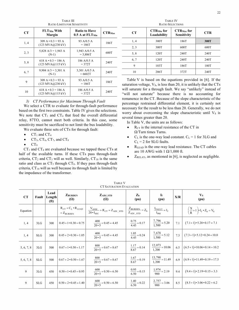
22
TABLE III RATIO LIMITS FOR SENSITIVITY
CT FLTMin With Margin
Ratio to Have 0.5 A at FLTMin CTRMax
1, 4 309 A • 0.3 = 93 A (123 MVA@230 kV)
93 A/0.5 A = 186T 186T
2, 3 5,828 A/3 = 1,943 A (N-1)
1,943 A/0.5 A = 3,886T 600T
5, 8 618 A • 0.3 = 186 A (123 MVA@115 kV)
186 A/0.5 A = 372T 240T
6, 7 9,904 A/3 = 3,301 A (N-1)
3,301 A/0.5 A = 6602T 240T
9 309 A • 0.3 = 93 A (123 MVA@230 kV)
93 A/0.5 A = 186T 186T
10 618 A • 0.3 = 186 A (123 MVA@115 kV)
186 A/0.5 A = 372T 240T
3) CT Performance for Maximum Through Fault We select a CTR to evaluate for through-fault performance
based on the first two constraints. Table IV gives the selections. We note that CT1 and CT4 that feed the overall differential relay, 87TO, cannot meet both criteria. In this case, some sensitivity must be sacrificed to not limit the bus loadability.
We evaluate three sets of CTs for through fault: • CT1 and CT4 • CT5, CT6, CT7, and CT8 • CT9 CT1 and CT4 are evaluated because we tapped these CTs at
half of the available turns. If these CTs pass through-fault criteria, CT2 and CT3 will as well. Similarly, CT10 is the same ratio and class as CT5 through CT8. If they pass through-fault criteria, CT10 will as well because its through fault is limited by the impedance of the transformer.
TABLE IV RATIO SELECTIONS
CT CTRMin for Loadability
CTRMax for Sensitivity CTR
1, 4 300T 186T 300T
2, 3 300T 600T 600T
5, 8 120T 240T 240T
6, 7 120T 240T 240T
9 103T 186T 180T
10 206T 372T 240T
Table V is based on the equations provided in [6]. If the saturation voltage, VS, is less than 20, it is unlikely that the CTs will saturate for a through fault. We say “unlikely” instead of “will not saturate” because there is no accounting for remanence in the CT. Because of the slope characteristic of the percentage restrained differential element, it is certainly not necessary for the result to be less than 20. Generally, we do not worry about overcoming the slope characteristic until VS is several times greater than 20.
In Table V, the units are as follows: • RCT is the internal resistance of the CT in
Ω/Turn times Turns. • CL is the one-way lead constant. CL = 1 for 3LG and
CL = 2 for SLG faults. • RLEAD is the one-way lead resistance. The CT cables
are 10 AWG with 1 Ω/1,000 ft. • ZRELAY, as mentioned in [6], is neglected as negligible.
TABLE V CT SATURATION EVALUATION
CT Fault Lead
Length (ft)
ZBURDEN (Ω)
ZADJ_STD (Ω)
Zb (pu)
If (pu) X/R VS
(pu)
Equation CT L LEAD
BURDEN
R C • RZ
+
= ANSI
CT ADJ _ STDSEC
V R Z20 • I
+ = BURDENb
ADJ _ STD
Z ZZ
= FAULTf
PRI
I II
= f b SX 1 • I • Z VR
+ =
1, 4 3LG 300 0.45 1• 0.30 0.75+ = 400 0.45 4.4520 • 5
+ = 0.75 0.174.45
= 7,796 5.201,500
= 7.1 ( )7.1 1 • 5.20 • 0.17 7.1+ =
1, 4 SLG 300 0.45 2 • 0.30 1.05+ = 400 0.45 4.4520 • 5
+ = 1.05 0.244.45
= 7,678 5.121,500
= 7.3 ( )7.3 1 • 5.12 • 0.24 10.0+ =
5, 6, 7, 8 3LG 500 0.67 1• 0.50 1.17+ = 800 0.67 8.6720 • 5
+ = 1.17 0.148.67
= 12,073 10.061,200
= 6.5 ( )6.5 1 •10.06 • 0.14 10.2+ =
5, 6, 7, 8 SLG 500 0.67 2 • 0.50 1.67+ = 800 0.67 8.6720 • 5
+ = 1.67 0.198.67
= 13,790 11.491,200
= 6.9 ( )6.9 1 •11.49 • 0.19 17.5+ =
9 3LG 450 0.50 1• 0.45 0.95+ = 600 0.50 6.5020 • 5
+ = 0.95 0.156.50
= 1,974 2.19900
= 9.4 ( )9.4 1 • 2.19 • 0.15 3.3+ =
9 SLG 450 0.50 2 • 0.45 1.40+ = 600 0.50 6.5020 • 5
+ = 1.40 0.226.50
= 2,757 3.06900
= 8.5 ( )8.5 1 • 3.06 • 0.22 6.2+ =
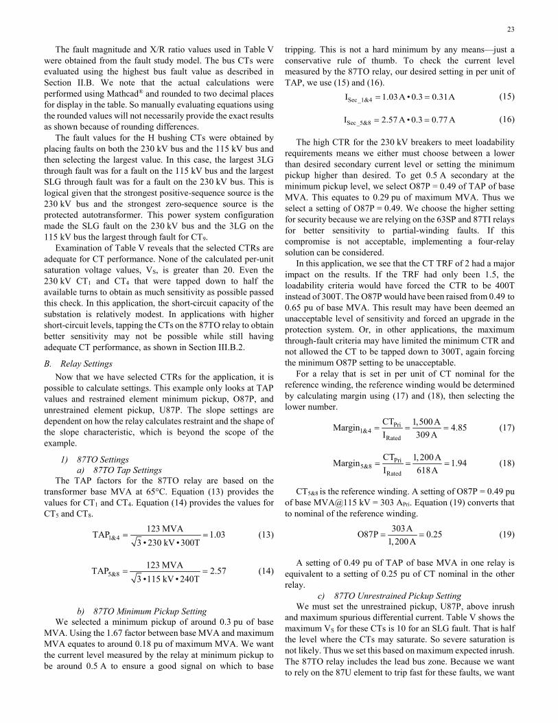
23
The fault magnitude and X/R ratio values used in Table V were obtained from the fault study model. The bus CTs were evaluated using the highest bus fault value as described in Section II.B. We note that the actual calculations were performed using Mathcad® and rounded to two decimal places for display in the table. So manually evaluating equations using the rounded values will not necessarily provide the exact results as shown because of rounding differences.
The fault values for the H bushing CTs were obtained by placing faults on both the 230 kV bus and the 115 kV bus and then selecting the largest value. In this case, the largest 3LG through fault was for a fault on the 115 kV bus and the largest SLG through fault was for a fault on the 230 kV bus. This is logical given that the strongest positive-sequence source is the 230 kV bus and the strongest zero-sequence source is the protected autotransformer. This power system configuration made the SLG fault on the 230 kV bus and the 3LG on the 115 kV bus the largest through fault for CT9.
Examination of Table V reveals that the selected CTRs are adequate for CT performance. None of the calculated per-unit saturation voltage values, VS, is greater than 20. Even the 230 kV CT1 and CT4 that were tapped down to half the available turns to obtain as much sensitivity as possible passed this check. In this application, the short-circuit capacity of the substation is relatively modest. In applications with higher short-circuit levels, tapping the CTs on the 87TO relay to obtain better sensitivity may not be possible while still having adequate CT performance, as shown in Section III.B.2.
B. Relay Settings Now that we have selected CTRs for the application, it is
possible to calculate settings. This example only looks at TAP values and restrained element minimum pickup, O87P, and unrestrained element pickup, U87P. The slope settings are dependent on how the relay calculates restraint and the shape of the slope characteristic, which is beyond the scope of the example.
1) 87TO Settings a) 87TO Tap Settings
The TAP factors for the 87TO relay are based on the transformer base MVA at 65°C. Equation (13) provides the values for CT1 and CT4. Equation (14) provides the values for CT5 and CT8.
1&4123 MVATAP 1.03
3 • 230 kV •300T= = (13)
5&8123 MVATAP 2.57
3 •115 kV • 240T= = (14)
b) 87TO Minimum Pickup Setting
We selected a minimum pickup of around 0.3 pu of base MVA. Using the 1.67 factor between base MVA and maximum MVA equates to around 0.18 pu of maximum MVA. We want the current level measured by the relay at minimum pickup to be around 0.5 A to ensure a good signal on which to base
tripping. This is not a hard minimum by any means—just a conservative rule of thumb. To check the current level measured by the 87TO relay, our desired setting in per unit of TAP, we use (15) and (16). Sec_1&4I 1.03A • 0.3 0.31A= = (15)
Sec_5&8I 2.57 A • 0.3 0.77 A= = (16)
The high CTR for the 230 kV breakers to meet loadability requirements means we either must choose between a lower than desired secondary current level or setting the minimum pickup higher than desired. To get 0.5 A secondary at the minimum pickup level, we select O87P = 0.49 of TAP of base MVA. This equates to 0.29 pu of maximum MVA. Thus we select a setting of O87P = 0.49. We choose the higher setting for security because we are relying on the 63SP and 87TI relays for better sensitivity to partial-winding faults. If this compromise is not acceptable, implementing a four-relay solution can be considered.
In this application, we see that the CT TRF of 2 had a major impact on the results. If the TRF had only been 1.5, the loadability criteria would have forced the CTR to be 400T instead of 300T. The O87P would have been raised from 0.49 to 0.65 pu of base MVA. This result may have been deemed an unacceptable level of sensitivity and forced an upgrade in the protection system. Or, in other applications, the maximum through-fault criteria may have limited the minimum CTR and not allowed the CT to be tapped down to 300T, again forcing the minimum O87P setting to be unacceptable.
For a relay that is set in per unit of CT nominal for the reference winding, the reference winding would be determined by calculating margin using (17) and (18), then selecting the lower number.
Pri1&4
Rated
CT 1,500AMargin 4.85I 309A
= = = (17)
Pri5&8
Rated
CT 1,200AMargin 1.94I 618A
= = = (18)
CT5&8 is the reference winding. A setting of O87P = 0.49 pu of base MVA@115 kV = 303 APri. Equation (19) converts that to nominal of the reference winding.
303AO87P 0.251,200A
= = (19)
A setting of 0.49 pu of TAP of base MVA in one relay is equivalent to a setting of 0.25 pu of CT nominal in the other relay.
c) 87TO Unrestrained Pickup Setting We must set the unrestrained pickup, U87P, above inrush
and maximum spurious differential current. Table V shows the maximum VS for these CTs is 10 for an SLG fault. That is half the level where the CTs may saturate. So severe saturation is not likely. Thus we set this based on maximum expected inrush. The 87TO relay includes the lead bus zone. Because we want to rely on the 87U element to trip fast for these faults, we want

24
a multiple of pickup of 2, if possible. If VS had been significantly over 20, as would have been the case for the example shown in Fig. 11, we might apply this margin factor of 2 to the maximum fault to allow up to 50% spurious differential current for a maximum through fault.
Table III shows the minimum fault on the 230 kV side is 5,820 A and the minimum fault on the 115 kV side is 9,904 A. Equations (20) and (21) show settings that meet these criteria.
1&2
5,820 A2U87P 9.4 pu
300T •1.03= = (20)
1&2
9,904 A2U87P 8.0pu
240T • 2.57= = (21)
For inrush, a conservative estimate is 8 pu of base MVA. So we select a setting of 8 times TAP that should be secure for inrush and operate fast for a fault on the high-side or low-side lead bus, allowing for a reasonable amount of spurious differential current.
Again, to convert this setting to an equivalent setting for a relay that is set in per unit of CT nominal, we convert the setting to primary amperes for the reference input. As shown in the previous section, CT5&8 is the reference winding. A setting of U87P = 8 pu = 4,944 APri. Equation (22) converts this value to nominal of the reference winding.
4,944AU87P 4.121,200A
= = (22)
A setting of 8 in per unit of TAP of base MVA in one relay is equivalent to a setting of 4.12 pu of CT nominal in the other relay.
2) 87TI Settings a) 87TI TAP Settings
The TAP factors for the 87TI relay are based on the transformer base MVA at 65°C. Equation (23) provides the values for CT9. TAP10 will be 2.57—same as TAP5&8.
9123 MVATAP 1.72
3 • 230 kV •180T= = (23)
b) 87TI Minimum Pickup Setting The criterion for the 87TI relay O87P setting is the same as
used for 87TO. To check the current level measured by the 87TI relay, our desired setting in per unit of TAP, we use (24) for CT9. Equation (16) gives the value for CT10, 0.77 A, the same as CT5&8. Sec_9I 1.72 A • 0.3 0.51 A= = (24)
We see that our desired sensitivity in per unit of base MVA is easily achieved with a good secondary current level measured by the 87TI relay. Separating the transformer zone from the bus zone paid off in this application.
c) 87TI Unrestrained Pickup Setting Again, we must set the unrestrained pickup, U87P, above
inrush. But this time, we are not concerned with maximum
spurious differential current because a through fault for this relay is limited by the impedance of the transformer. Table V shows that maximum VS for CT9 is only 6. Thus, we set the pickup based on maximum expected inrush. We would still like to obtain a multiple of pickup of 2 for fast operation for a bolted internal fault.
Equation (25) gives the U87P setting that meets this criterion for CT9. Equation (21) gives the value for CT10, 8.0, the same as CT1&4.
9
5,820 A2U87P 9.4 pu
180T •1.72= = (25)
Not surprisingly, we see that (20) for 87TO and (25) for 87TI evaluate to the same value because they are both in per unit of base MVA and CT saturation for external faults is not a concern. Again, we select a setting of U87P = 8 times TAP that should be secure for inrush and operate fast for a bolted internal fault, allowing for a reasonable amount of spurious differential current.
3) 87BHL Settings a) 87BHL TAP Settings
The TAP factors for the 87BHL relay are based on the bus rating of 3,000 A. Thus, TAP2 and TAP4 are 5.00. We use (1) to calculate TAP9. Equation (26) provides the value.
93,000 ATAP 16.67
180T= = (26)
b) 87BHL Minimum Pickup Setting The criterion for 87BHL relay O87P setting is below the
minimum bus fault with margin. A margin of 3 was used in developing Table III. We can use a greater sensitivity margin (Margin = 3) for this element over what was used for the unrestrained element (Margin = 2) because of the security provided by the percentage restraint characteristic. If possible, a setting above maximum load can provide security for accidental opening of a CT test switch. But the dependability limit is more important. Equation (27) provides the setting based on minimum fault current with margin.
5,828 A
3O87P 0.64 pu600T •5.00
= = (27)
With a margin factor of 3, our desired sensitivity in per unit of bus rating is below the maximum load current (1 pu). Because the dependability limit is most important, we set O87P = 0.64 pu.
There is no U87P setting for this relay because the bus-zone relay would have its harmonic functions turned off (if the feature is present).
4) 87BLL Settings a) 87BLL TAP Settings
The TAP factors for the 87BLL relay are based on the bus rating of 1,200 A. Because all CTs have the same primary rating, TAP6, TAP7, and TAP10 are set to 5.00.

25
b) 87BLL Minimum Pickup Setting The criterion for 87BLL relay O87P setting is below the
minimum bus fault with margin. A margin of 3 was used in developing Table III. If possible, a setting above maximum load can provide security for accidental opening of a CT test switch. Equation (28) provides the setting based on minimum fault current with margin.
9,904 A
3O87P 2.72 pu240T •5.00
= = (28)
With a margin factor of 3, our desired sensitivity in per unit of bus rating is much higher than the maximum load current. Because there is no reason to set it higher than the maximum load current, we set O87P = 1.00 pu.
X. ACKNOWLEDGMENT The authors would like to thank Jordan Bell of SEL
Engineering Services, Inc. for validating the bus differential element logic code detailed in Appendix A and performing testing using a real-time digital simulator to obtain the performance graphs presented in the paper.
XI. REFERENCES [1] B. Kasztenny, M. J. Thompson, and D. Taylor, “Time-Domain Elements
Optimize the Security and Performance of Transformer Protection,” proceedings of the 71st Annual Conference for Protective Relay Engineers, College Station, TX, March 2018.
[2] J. D. McDonald, Electric Power Substations Engineering, 3rd ed. CRC Press, Boca Raton, FL, 2012.
[3] A. Hargrave, M. J. Thompson, B. Heilman, “Beyond the Knee Point: A Practical Guide to CT Saturation,” proceedings of the 71st Annual Conference for Protective Relay Engineers, College Station, TX, March 2018.
[4] IEEE C37.110-2007, IEEE Guide for the Application of Current Transformers Used for Protective Relaying Purposes.
[5] S. E. Zocholl, “Rating CTs for Low Impedance Bus and Machine Differential Applications,” proceedings of the 54th Annual Conference for Protective Relay Engineers, College Station, TX, April 2001.
[6] M. Thompson, R. Folkers, and A. Sinclair, “Secure Application of Transformer Differential Relays for Bus Protection,” proceedings of the 58th Annual Conference for Protective Relay Engineers, College Station, TX, April 2005.
[7] B. Kasztenny, M. Thompson, and N. Fischer, “Fundamentals of Short-Circuit Protection for Transformers,” proceedings of the 63rd Annual Conference for Protective Relay Engineers, College Station, TX, March 2010.
[8] J. L. Blackburn, Protective Relaying: Principles and Applications, 1st ed. Marcel Dekker, Inc., New York, NY, 1987.
[9] IEEE C37.234-2009, IEEE Guide for Protective Relay Applications to Power System Buses.
[10] M. J. Thompson, “Percentage Restrained Differential, Percentage of What?,” proceedings of the 64th Annual Conference for Protective Relay Engineers, College Station, TX, April 2011.
[11] IEEE C37.91-2008, IEEE Guide for Protecting Power Transformers. [12] B. Kasztenny, N. Fischer, and H. J. Altuve, “Negative-Sequence
Differential Protection – Principles, Sensitivity, and Security,” proceedings of the 68th Annual Conference for Protective Relay Engineers, College Station, TX, April 2015.
[13] M. Thompson, F. K. Basha, and C. Holt, “Modern Protection of Three-Phase and Spare Transformer Banks,” proceedings of the 69th Annual Conference for Protective Relay Engineers, College Station, TX, April 2016.
[14] Central Station Engineers of the Westinghouse Electric Corporation, Electrical Transmission and Distribution Reference Book, 4th ed., Pittsburgh: Westinghouse, 1964, pp. 172.
[15] IEEE C57.12.10-2010, IEEE Standard Requirements for Liquid-Immersed Power Transformers.
[16] NERC Standard TPL-001-4 — Transmission System Planning Performance Requirements.
XII. BIOGRAPHIES Shahab Uddin received his bachelor’s degree in electrical engineering from Jamia Millia Islamia, India, in 1999, M.S. in electric power engineering from Rensselaer Polytechnic Institute in 2003, and M.B.A. from University of New Hampshire in 2010. Upon graduating, he served eight years at Northeast Utilities (now Eversource Energy) in various departments such as Transmission Protection and Control, Transmission Operations, and Sub-Transmission Planning and Strategy. Since 2011, he has been with American Electric Power in the Transmission Protection and Control department. Shahab is presently a supervisor and is responsible for electrical service in the Oklahoma area.
Abu Sayeed Bapary received his B.S. in electrical and electronic engineering from Bangladesh University of Engineering and Technology in 1992. Upon graduating, he served nearly nine years in various capacities in Bangladesh in electrical substation design, protection, and control engineering. After earning his M.S. in electrical and computer engineering from Concordia University, Montreal, Canada, in 2006, he joined American Electric Power as a protection and control engineer and presently works as a principal engineer in the Protection and Control Engineering department. He is a member of the IEEE and is an active member of the IEEE PES Power System Relaying and Control Committee. Abu is a registered professional engineer in the state of Oklahoma.
Michael Thompson received his B.S., magna cum laude, from Bradley University in 1981 and M.B.A. from Eastern Illinois University in 1991. Upon graduating, he served nearly fifteen years at Central Illinois Public Service (now AMEREN). Prior to joining Schweitzer Engineering Laboratories, Inc. (SEL) in 2001, he was involved in the development of several numerical protective relays while working at Basler Electric. He is presently a fellow engineer at SEL Engineering Services, Inc. He is a senior member of the IEEE, member of the IEEE PES Power System Relaying and Control Committee (PSRCC), past chairman of the Substation Protection Subcommittee of the PSRCC, and recipient of the Standards Medallion from the IEEE Standards Association in 2016. Michael is a registered professional engineer in six jurisdictions, was a contributor to the reference book Modern Solutions for the Protection Control and Monitoring of Electric Power Systems, has published numerous technical papers and magazine articles, and holds three patents associated with power system protection and control.
Ryan McDaniel earned his B.S. in computer engineering from Ohio Northern University in 2002. In 1999, he was hired by American Electric Power (AEP) as a relay technician, where he commissioned protective systems. In 2002, he began working in the Station Projects Engineering group as a protection and control engineer. His responsibilities in this position included protection and control design for substation, distribution, and transmission equipment as well as coordination studies for the AEP system. In 2005, he joined Schweitzer Engineering Laboratories, Inc. and is currently a senior field application engineer. His responsibilities include providing application support and technical training for protective relay users. Ryan is a registered professional engineer in the state of Illinois and a member of the IEEE.
Kunal Salunkhe received his B.E. in Electrical Engineering from University of Pune, India, in 2006, and M.S. in Electrical Engineering from University of Houston in 2011. Upon graduation, he joined Schweitzer Engineering Laboratories, Inc. His responsibilities include protection and control system design for distribution, and transmission substations. He also provides power system studies for utility and industrial customers. Kunal is a registered professional engineer in the state of Texas and a member of the IEEE.
© 2018 by American Electric Power and Schweitzer Engineering Laboratories, Inc.
All rights reserved. 20181207 • TP6877-01