application and network layers design for
TRANSCRIPT

International Journal of Computer Science, Engineering and Applications (IJCSEA) Vol.4, No.6, December 2014
DOI : 10.5121/ijcsea.2014.4605 53
APPLICATION AND NETWORK LAYERS DESIGN FORWIRELESS SENSOR NETWORK TO SUPERVISECHEMICAL ACTIVE PRODUCT WAREHOUSE
Ahmed Zouinkhi, Kais Mekki, Mohamed Naceur Abdelkrim
Research unit of Modeling, Analysis and Control of Systems (MACS)National Engineering School of Gabes, rue Omar Ibn Elkhattab, 6029 Gabes, Tunisia.
ABSTRACT
Wireless sensor networks have profound effects on many application fields like security management whichneed an immediate and fast system reaction. Indeed, the monitoring of a dangerous product warehouse is amajor issue in chemical industry field. This paper describes the design of chemical warehouse securitysystem using the concept of active products and wireless sensor networks. A security application layer isdeveloped to supervise and exchange messages between nodes and the control center to prevent industrialaccident. Different security rules are proposed on this layer to monitor the internal state and incompatibleproducts distance. If a critical event is detected, the application generates alert message which need a shortend to end delay and low packet loss rate constraints by network layer. Thus, a QoS routing protocol isalso developed in the network layer. The proposed solution is implemented in Castalia/OMNeT++simulator. Simulation results show that the system reacts perfectly for critical event and can meet the QoSconstraints of alert message.
KEYWORDS
Security System, Active Product, Wireless Sensor Networks, Routing protocol, Quality of Service, CastaliaSimulation
1. INTRODUCTION
In recent years, the rapid technological advances in low power and highly integrated digitalelectronics, small scale energy supplies, and low power radio technologies have created low costand multifunctional intelligent devices. These devices are equipped with small battery, a tinymicroprocessor, a radio transceiver and a set of sensor modules that used to acquire informationof their surrounding environment. These technological advances lead to different new researchfield such as Internet of Things [1] and Active Product [2].
The active intelligent product had large expansion on the industry. Through this concept, theindustrial product is not simply a physics entity but it is an active object which is able tocommunicate and exchange information with the systems. These capacities were made with theRFID identification technology (Radio Frequency Identification) [3] and the Wireless SensorsNetworks (WSN). However unlike RFID, WSN allows going beyond the information exchange tothe sensing of ambient environment parameters (e.g. temperature, pressure, humidity…) [4].
International Journal of Computer Science, Engineering and Applications (IJCSEA) Vol.4, No.6, December 2014
54
This concept attracted the interest of several research projects. As example, COBIS project(Collaborative Business Items) [5,6] has developed a new approach for business processesinvolving physical entities such as goods and tools in enterprise. COBIS improved the networkedsystems to create cooperative products named particles, used for various applications particularlyfor monitoring the industrial products. TecOlab from Karlsruhe University and MIT [7] hasannounces the concept of active physical documents for the integrity management of written filesto restrict accesses and keep the track of the document changes. It introduces the DigiClip systemthat provides a solution to convert passive paper documents to active physical entities. Moreover,CHAOS project [8] also employs the intelligent object approach to secure the exchange ofinformation in distributed systems.
The security of industrial chemical products is an important issue. So, the using of active producttechnology may facilitate its supervising process. The security of such product involves theinternal reaction against the ambient values changes (e.g. temperature) and the incompatibility ofchemical substances during the storage and transport phases.
This paper proposes a security system of chemicals products warehouse. Such storage productsmay cause critical danger if security rules are not respected. The container of chemical substancesis transformed into a communicating entity (i.e. active product) by embedding a wireless sensornode. Thus, the container could supervise its internal state and the external changes of itsenvironment (e.g. temperature, brightness, and humidity). Moreover, the containers could controlthe distance between them by periodic message exchange (RSSI method [9]) to prevent thecloseness of the incompatible chemical substance. If there are critical and alert events (e.g. hightemperature, incompatible products are very close), the node is able to make decisions and sendsalert messages to the control center (sink node).
The developed system uses a centralized approach and point-to-point connection for the controlcenter to communicate with nodes using a specific security application layer of WSN (i.e. the sinkcommunicates directly with the nodes in the warehouse). However, the supervised nodes use amulti-hops connection to communicate and send messages to the control center (i.e. the messagespasses from one node to another until it reaches the sink). This last case requires a routingprotocol development in the network layer of sensor nodes. Indeed, the security application layergenerates two classes of message: alert message and routine message (i.e. daily exchangedmessage). An alert message should be encapsulated in high priority packet in the network layerand routed across the WSN toward the sink node. Such packet requires strict constraints on bothdelay and loss ratio in order to report the message to the control center within certain time limitswithout loss. These performance metrics (delay and loss ratio) are usually referred to as Qualityof Service (QoS) requirements [10]. Thus, enabling high priority packet in the network layerrequires QoS based routing protocol. Many QoS based routing protocols specifically designed forWSN have been proposed in the literature, for example, SPEED [11], AODV [12], RPAR [13],THVR [14], RRR [15], EQSR [16], and MARP [17]. For our chemical security system, we haddeveloped routing strategies for each classe of messages. Disjoint multi-paths routing is proposedfor alert message. However, the routing algorithm employs neighborhood gathering informationand next node selection phase for routine message.
These developed application and network layers have been implemented and simulated usingCastalia/OMNeT++ tools. The security system is then evaluated by studying the message deliveryratio, end to end delay, and alert detection validation.
The rest of paper is organized as follows. In the next section, the communication topology of thesecurity system is presented. In section 3, the security rules are detailed. And, section 4 and 5
International Journal of Computer Science, Engineering and Applications (IJCSEA) Vol.4, No.6, December 2014
55
present the application and network layers design, respectively. Then in section 6, theperformance of the proposed solution is analyzed. Finally, section 7 concludes the paper.
2. COMMUNICATION TOPOLOGY OF THE ACTIVE CHEMICALPRODUCT SECURITY SYSTEM
2.1. The active chemical product
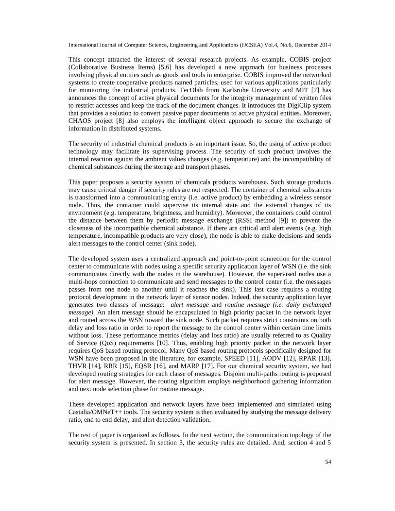
The concept of active product consists in endowing a product with the capacities ofcommunicating, informing, acquiring, deciding, and reacting to the changes of its ambientenvironment [18,19]. This concept is used in our security system by integrating wireless sensornode in every chemical container as shown in figure 1. Thus, each container is upgraded withsensing, computation, interaction, and communication capacities.
Figure 1. Transformation of the chemical container into active product
2.2. The network communication topology
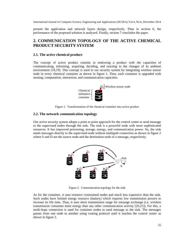
Our active security system adopts a point to point approach for the control center to send messageto the supervised nodes through the sink. The sink is a powerful node with more sophisticatedresources. It has improved processing, storage, energy, and communication power. So, the sinksends messages directly to the supervised node without multipath connection as shown in figure 2where S and D are the source node and the destination node of a message, respectively.
Figure 2. Communication topology for the sink
As for the container, it uses resource constrained nodes and much less expensive than the sink.Such nodes have limited energy resource (battery) which requires low transmission powers toincrease its life time. Thus, it uses short transmission range for message exchange (i.e. wirelesstransmission consumes more energy than any other communication activity [20,21]). For this, amulti-hops connection is used for container nodes to send message to the sink. The messagespasses from one node to another using routing protocol until it reaches the control center asshown in figure 3.
Wireless sensor nodeChemicalsubstancecontainer
Sink
S
D
D
D D

International Journal of Computer Science, Engineering and Applications (IJCSEA) Vol.4, No.6, December 2014
56
Figure 3. Communication topology for the container
3. SYSTEM SECURITY RULES
The system security rules define the chemical substance state of each supervised container. Thevariation of certain ambient environment such as the temperature could lead to critical industrialaccident. Moreover, different chemical substances are stored in the same warehouse and somesubstances could be incompatible with others. For this reasons, the following critical chemicalfactors are considered:
- The ambient temperature: some chemical substances could lead to dangerous explosionor flame. So through temperature thresholds (min and max), the internal state of thecontainer could be supervised.
- The product incompatibility: the distance between containers is supervised to prevent allpossible dangerous reaction of the incompatible chemical substances.
To control these factors, the following security rules are developed: static, dynamics, community,and global rules.
3.1. Static rules
The container node employs temperature sensor. In order to avoid critical reactions, the static rulerequires that the ambient temperature value didn’t exceed a threshold values (min and max). Thisthreshold is defined according to the chemical substance characteristics.
So, each sensed temperature value Vsr is characterized by two critical values Vsrmin and Vsrmax
associated with a safety margin ΔVsr. For each node i, the security level Ssr of the static rules isevaluated as follow:
- G: if the value of the sensor i defines a good state.- B: if the value announces a bad state.- D: if the value indicates a dangerous state.
The statics rules Ssr are presented by the equation 1.
(1)

International Journal of Computer Science, Engineering and Applications (IJCSEA) Vol.4, No.6, December 2014
57
3.2. Dynamic rules
The purpose of these rules is to supervise the temporal variation of the static rules. If a bad statepersists for period of time, a dangerous state is announced. Moreover, a counter is implemented togather the switch between good and bad states. If the counter exceeds a threshold value nc, adanger state is announced. The dynamic rules Sdr are presented by the equation 2.
With:
- Tcr: is a critical period of time. It is fixed according to the chemical product that notovercomes when a bad state is reached.
- nc: is the number of authorized Ssr switch between states G and B.- Occur(x): is a function initialized to zero and incremented when Ssr switch from state G to
B.
3.3. Community rules
Some products could have incompatibility constraints according to their chemical characteristics.Such constraint is proportional to the distance between chemical products (container). Forexample, the chemical symbols H2SO4 and HF are incompatible and represent a danger if thedistance between them is under a predefined threshold value [19]. The community rules Scr couldlead to one of the three states as described in equations 3, 4, and 5.
With:
- Fcomp(x,y): is a function which studies the compatibility between the chemical symbols oftwo products Pi and Pj.
- D(x, y): is the distance between two products Pi and Pj..- Dmin: is a critical distance (threshold) that must be respected between incompatible
products.- ∆D: is a distance margin fixed according to the chemical characteristic of the product.
(2)
(3)
(4)
(5)
International Journal of Computer Science, Engineering and Applications (IJCSEA) Vol.4, No.6, December 2014
58
3.4. Global rules
After calculate the state of each rule (static, dynamic, and community), it is necessary to get theglobal security state Sgr. Sgr describes the global state of the product as described in equations 6.Sgr= f (Ssr, Sdr, Scr)
With: α={sr, dr, cr}
4. APPLICATION LAYER PROTOCOL
This section describes the active product behavior. And, it presents the control_center/productand product/product messages exchange to achieve permanent supervising of the warehouse. Thechemical product is active using the following parts: registration, configuration, internalsurveillance, and alert announcement.
4.1. Registration part
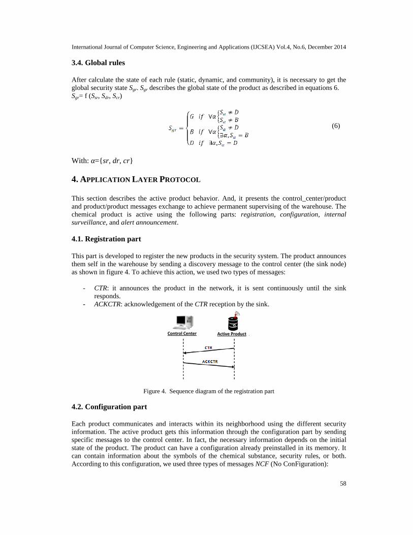
This part is developed to register the new products in the security system. The product announcesthem self in the warehouse by sending a discovery message to the control center (the sink node)as shown in figure 4. To achieve this action, we used two types of messages:
- CTR: it announces the product in the network, it is sent continuously until the sinkresponds.
- ACKCTR: acknowledgement of the CTR reception by the sink.
Figure 4. Sequence diagram of the registration part
4.2. Configuration part
Each product communicates and interacts within its neighborhood using the different securityinformation. The active product gets this information through the configuration part by sendingspecific messages to the control center. In fact, the necessary information depends on the initialstate of the product. The product can have a configuration already preinstalled in its memory. Itcan contain information about the symbols of the chemical substance, security rules, or both.According to this configuration, we used three types of messages NCF (No ConFiguration):
(6)
Control Center Active Product

International Journal of Computer Science, Engineering and Applications (IJCSEA) Vol.4, No.6, December 2014
59
- NCF0: if the product has neither the security symbol nor its security rules.- NCF1: if the product has only the security symbols.- NCF2: if the product has only the configuration of its security rules.
These previous messages are sent continuously until the sink responds as shown in figure 5. In theother side, the control center responds with the following messages:
- CMD1: it contains the configuration of the product security symbols.- CMD3: it contains the configuration of the different security rules.-
Figure 5. Sequence diagram of the configuration part
4.3. Internal supervising part
Once the product is correctly configured, it becomes able to supervise its internal state andneighborhood. Any change of its environment or approximation of incompatible neighbor productmust be detected using the safety rules. This supervising process is developed using the followingmessages:
- GRE: it is a greeting message periodically exchanged between neighbor products in thewarehouse. It carries the product information (name, security symbols) and its currentsecurity level. It is used also to calculate the distance between two active products.
- RSI: it contains the received signal strength indicator (RSSI). This information is used toestimate the distance between neighbor products, and calculate the community rules. Infact, we used an equivalence-based solution between the received RSSI and the realdistance value that separating two products. This equivalence is presented in figure 6.When the active product receives RSI message, the node calculates the RSSI value. Then,it determines the equivalent distance and verifies if this distance exceeded the thresholdDmin.
Figure 6. Distance between products versus RSSI values
Control Center Active Product

International Journal of Computer Science, Engineering and Applications (IJCSEA) Vol.4, No.6, December 2014
60
To achieve the internal supervising of chemical product, we used the following messages asshown in figure 7:
- CMD2: it is a request of the control center which requires the configuration of an activeproduct.
- CMD4: it is a request of the control center to get the security rules of an active product.- CMD5: it is a request of the control center to get specific ambient information of an
active product.- CFG: it contains the configuration of the product. It is sent after CMD2 reception.- SER: it contains the product security rules. It is sent after CMD4 reception.- INA: it carries the ambient sensed values of the product. It is sent after CMD5 reception.
Figure 7. Sequence diagram of the internal supervising part
4.4. Alert announcement part
This part employs an alert message named ALE (ALErt) which announces a dangerous state to thecontrol center and requires an immediate intervention as shown in figure 8.
- ALE: it announces the security alert to the control center. It contains the measurementsthat caused the alert. It is sent when the calculated security rules is considered dangerous(D) or Bad (B).
- ACKALE: acknowledgement of the ALE reception by the control center.
Figure 8. Sequence diagram of the alert announcement part
Control Center Active Product Active Product
Control Center Active Product

International Journal of Computer Science, Engineering and Applications (IJCSEA) Vol.4, No.6, December 2014
61
5. NETWORK LAYER PROTOCOL
GRE and RSI are broadcast messages (i.e. neighborhood exchanged messages) which don’t needrouting function toward the sink (control center). However, the product_node/sinkcommunication needs routing protocol to deliver message and allow communication betweenthem. In the following, the routing protocol is presented.
5.1. Gradient setup phase
The network layer protocol employs a gradient setup phase to construct the necessary informationfor routing path selection: neighborhood table and hop count. This phase is executed periodicallysince the control center begins supervising the warehouse. It works as follow: the sink broadcastsa HELLO packet only to its neighbors using low transmission range (the same transmission rangeof the supervised nodes), the HELLO packet contains: the hop count HC (initial value = 0) andthe sender address SA. HC is used to setup the gradient to the sink (i.e. HC is the distancebetween a supervised node and the sink), and SA is used to build the neighborhood table of eachnode. After broadcasting HELLO by the sink, all its neighbors nodes receive this packet and eachone executes the following steps:
If the node doesn’t have a gradient:1) Saves SA and HC of the sender node in its neighbors table.2) Increments HC by 1.3) Registers HC in its memory.4) The HC field is then replaced in the HELLO packet with the new one.5) Broadcasts HELLO to farther nodes (neighbors nodes).
If the node has a gradient:
1) Gets SA and HC of the sender node. If SA doesn’t exist in its neighbors table, SA andHC information are saved to the table. Else, the corresponding HC is replaced withthe new one.
2) Increments HC by 1.3) Compares its gradient to HC. If the latter is smaller, the node replaces its gradient
with HC, puts HC in the HELLO packet and broadcasts it. However, if its gradient issmaller than or equal to the HC, the node discards the packet. As a result, thegradient will memorize the short path toward the sink.
This process will continue until all the supervised nodes receive the HELLO packet. At that time,the gradient setup phase will be completed. As result, each node knows its distance HC (numberof hops) to the sink, its entire neighbours and their gradient (neighbors table). Then, the nodes canstarts routing packets to the control center (sink node) through the routing phase.
5.2. Routing phase
Our security application layer has two types of product/control_center exchanged messages: alertmessage (ALE) which requires high quality of service (e.g. short delay, low packet loss, faulttolerance), and routine messages (CTR, NCF, CMD,…). Thus, we had to use different strategy forthe routing of such information. Moreover, in industrial environments, several faults could lead tofailures of nodes in WSN. So, our routing solution has to be fault-tolerant to resist to failed nodes.The routing protocol of our security system has to take in consideration all this constraint, keeps a

International Journal of Computer Science, Engineering and Applications (IJCSEA) Vol.4, No.6, December 2014
62
low communication overhead, and reduces the energy consumption as much as possible. In thefollowing, the different strategies for routing alert message and routine message are presented.
5.2.1. Routing of alert message
For ALE message, the multi-paths routing is chosen to enhance the reliability and the faulttolerance of our security system. The ALE source node starts multi-paths routing and creates a setof neighbors that able to forward the message towards the sink. The constructed multi-paths arenode-disjoint (i.e. the multi-paths have no common nodes except the ALE source and the sink).Node-disjoint are usually preferred in multi-paths routing because they utilize the most availableWSN resources, and hence are the most fault-tolerant [16]. If an intermediate node in a set ofnode-disjoint paths fails, only the path containing that node is affected. In the following, ourmulti-paths construction is detailed:
- Primary path routing: Through the neighbor table, the source selects the node which has thelowest gradient HC to the sink as next hop, and sends the ALE packet to this selected node.Similarly through its neighbor table, the next hop node of the source choose the closest nodeas next hop in the direction of the sink and sends out the ALE packet. The operationcontinues until sink node receives the packet as shown in figure 9.
- Alternative path routing: For the second alternate path, the source node sends ALE packet toits next most preferred neighbor (the second closest neighbor to the sink). To avoid havingpaths with shared nodes, each node is limited to accept only one ALE packet. For thosenodes that receive more than one ALE packet, only accept the first one and reject the others.In the example of figure 9, node 9 computes it’s next preferred neighbor and finds it node 7.Node 9 forwards the packet to node 7, but node 7 has been included in the primary path,then node 7 simply responds to node 9 with an INUSE packet [16] indicating that node 7 isalready selected in a routing path. Immediately node 9 searches its neighboring table andselects the next preferred neighbor which will be node 5, and sends out the packet to it.Node 5 accepts the packet and continues the procedure in the direction of the sink.
Figure 9. Node-disjoint paths routing
5.2.2. Routing of routine message
For routine message (CTR, NCF, CMD…), another routing strategy is developed which allowsalso a continuous neighbor table updating. The protocol consists of two steps for sending themessage to the sink, first information gathering and then routing.
- Information gathering: When node needs to send routine packet to the sink, it broadcasts arequest to acquire the information from the neighboring nodes in its transmission range. Thenodes that received the request packet send their information to the source, the response
1
9 52
8 7 3SD
Sink
Alternative path
Primary path

International Journal of Computer Science, Engineering and Applications (IJCSEA) Vol.4, No.6, December 2014
63
contains the residual energy of the neighboring node. Indeed, this step is used to update theneighbor table of nodes which are involved in the route toward the sink. The source nodegets the ID of all current neighboring nodes from the received response packets, andcompare between the old neighbor table and the new one. The node from the old tablewhich is absent in the new one, are removed and the new detected nodes are added to thetable.
- Routing: After the information gathering finishes, the routing starts. The source choosesfrom its neighbor table two nodes that have the lowest gradient HC towards the sink asshown in figure 10(a). Then, the source compare between these two nodes according to theresidual energy, the nodes that had the highest residual energy level will be the next hop asshown in figure 10(b). If two nodes have the same residual energy level, the nodes that havea lower HC to the sink will be taken. After that, the source node sends the packet to theselected node. Upon receiving the packet, the node as next hop repeats the informationgathering and routing steps to transmit the packet to another node as shown in figure 10(c).The process continues until the packet reaches the sink (control center).
(a) (b) (c)
Source nodeNode with lowest gradient HCNode with highest residual energy level
Figure 10. Routing of routine packet
6. SIMULATION AND PERFORMANCE EVALUATION
In the following, the performance of the proposed security system is evaluated and discussed. Thesimulation settings are firstly detailed. Second, the performance results of the network layerprotocol are presented and discussed. Then, different cases of application layer message exchangeare studied.
6.1. Simulation setup
The security application and network layers were implemented with Castalia/OMNeT++ Tools.Currently, many wireless sensor network simulators are available as NS2 and SENSE but Castaliaprovides realistic wireless channel and radio models, and realistic node behavior especiallyrelating to access of the radio [22].
The Crossbow’s TelosB sensor node [23] is simulated which is one of the most used nodes in theindustry and research. Table 1 and figure 11 show the characteristic of TelosB node.

International Journal of Computer Science, Engineering and Applications (IJCSEA) Vol.4, No.6, December 2014
64
Table 1. TelosB node characteristics
Chipcon wirelesstransceiver
Data rate 250 kbpsFrequency
bands2.4 to 2.4835 GHZ
Protocol IEEE 802.15.4/ZigBee
Microprocessor MSP430Flash 48 Kb
RAM 10 Kb
EEPROM 1 Mb
ADC 12 bit
Serial Com UART
Currentdraw
Active 1.8 mASleep 5.1 µA
RF power -24 dBm to 0 dBmOutdoor Range 75 m to 100 mIndoor Range 20 m to 30 m
Battery 2 X AA batteries
Size 65 X 31 X 6 mm
Weight 23 Grams
Figure 11. TelosB node
The node positions of the simulated networks (warehouse) are all uniformly distributed within a300mx300m square (m=meters). All the nodes are stationary and the sink is located at the bottomof the square as shown in figure 12. IEEE 802.15.4 [24], a contention-based medium accesscontrol, is used as MAC protocol. The wireless radio channel characteristics such as the signalnoise, interference ratio, and average path loss, are chosen to simulate the realistic modeled radiowireless channel in Castalia based on the lognormal shadowing and the additive interferencemodels. The parameters used in this simulation study are summarized in table 2.
Table 2. Simulation parameters
Warehouse area 300m X 300mNodes distribution Uniform random
Location of Sink (control center) Bottom of the warehouse
MAC layer IEEE 802.15.4
Radio CC2420
Sigma channel parameter 4
Real radio wirelesschannel in Castalia
Bidirectional Sigma channel parameter 1
Radio Collision Model2 (additive interference
model)
Initial energy 18720 JSimulation time 1000 sNumber of trials 60

International Journal of Computer Science, Engineering and Applications (IJCSEA) Vol.4, No.6, December 2014
65
Figure 12. Nodes (active products) deployment
6.2. Studying the network layer performances
To study the routing protocol performances, we simulate the network under two state of traffic:
- Not congested traffic: the routine data packet rate is 0.2 pkt/s for each node, while the alerttraffic rate is 1 pkt/s at 2 nodes.
- Congested traffic: the routine data packet rate is 1 pkt/s for each node, while the alert trafficrate is 5 pkt/s at 4 nodes. The network load becomes higher now as there are more sourcesof alert packet with higher rate.
To evaluate the performance of our routing solution, we compared its performance with RandomRe-Routing protocol (RRR) [15,25] which uses also different strategy for routing of alert data androutine data. High priority packets of unusual events are routed along the preferred path (i.e. theshortest path), while the routine data packets are randomly shunted to slower and possibly longersecondary paths. In RRR, the sensor nodes change their routing policy adaptively according to thecurrent traffic level. When the overall total traffic level is low, the preferred path will be sharedby all packets. However, when the total traffic exceeds a given threshold (3 pkt/s of alert packets),the preferred path will be reserved for forwarding only the alert packets and secondary paths willbe used for the routine data packets. This mechanism provides significantly better QoS (i.e. lowdelay and high packet delivery ratio) to alert data.
In the following, the developed QoS-based routing protocol and RRR are compared in term of:average end to end delay and the packet loss ratio.
6.2.1. Average end to end delay
End to end delay is an important metric in evaluating the routing protocols [10]. Figures 13, 14,15, and 16 show the average end to end delay for each protocol and each type of packet for fourlevels of network density (200, 400, 600, and 800 nodes).
300
m
300 m

International Journal of Computer Science, Engineering and Applications (IJCSEA) Vol.4, No.6, December 2014
66
Before analyzing the performance of our routing solution, we present the result of RRR protocol.In congested traffic, the alert traffic rate at the intermediate nodes exceeds the threshold of RRRand then the alert packets are routed along the shortest path whereas the routine data packets areforwarded via random alternative paths. So as shown in figures 13 and 14, the alert data achieveslower packet delay than the routine data. Figures 15 and 16 show that the delay made for bothtypes of data for RRR are close, because this protocol does not differentiate between types ofpackets in not congested traffic (similar treatment for both packets).
For our network layer, the developed protocol successfully differentiates routing services as RRRprotocol. It is able to meet the time constraints for alert packets in both congested and notcongested traffic as shown in figures 13 and 15, the alert packet delay is the lowest even with theincreasing of the network density. RRR outperforms our protocol in the case of routing of routinedata packet as presented in figures 14 and 16. Furthermore, the average delay of routine data ishigher when density increases for our protocol because it suffers from a lost time on informationgathering phase. In this phase and for each received routine packet, the protocol broadcasts arequest and waits for responses from all the neighboring nodes to determine the next hop. So,when the number of neighboring nodes increases, the source node have to wait more time whichcauses more queuing and treatment delay for routine data packets despite it always chooses thepaths that have the minimum number of hops to the sink. Despite this, the information gatheringphase is necessary for our network layer to enhance security and fault tolerance.
In conclusion, our network layer performs better than RRR protocol in the end to end delay ofalert packets but not for routine data packets.
6.2.2. Packet Loss Ratio
Another important metric in evaluating routing protocols is the packet loss ratio [10]. Figures 17,18, 19, and 20 show the packet loss ratio for each protocol and each type of packet for four levelsof network density (200, 400, 600, and 800 nodes).
Figure 13. End to end delay in congestedtraffic, alert packet
Figure 14. End to end delay in congestedtraffic, routine packet
Figure 15. End to end delay in not congestedtraffic, alert packet
Figure 16. End to end delay in not congestedtraffic, routine packet

International Journal of Computer Science, Engineering and Applications (IJCSEA) Vol.4, No.6, December 2014
67
As expected, figures 17 and 19 show that our network layer guarantees a very low packet loss ratefor the ALE message in the two classes of traffic due to multipath routing. Discovering andmaintaining multiple paths between the source and the sink node improves the routingperformance by providing alternative paths. Primary and alternative paths are usedsimultaneously for data routing by sending multiple copies of alert packet across each path.Simultaneous multipath routing improves reliability. As long as, one of the multiple paths doesnot fail, the sink node will receive the alert packet.
RRR outperforms our protocol in the case of routine data packet because of the informationgathering phase as delay performance. In not congested traffic, the routine data have an averagepacket loss rate as shown in figure 20. Lost packets increase in the case of congested traffic asshown in figure 18, the analysis of trace files of Castalia simulator showed that the majority ofpackets are lost due to:
- Overloading of nodes causing saturation of the queues.- Interference because we have many transfers, so there is more concurrent access to the
radio channel.
Reasoning according to the density of the network, figures 17 and 19 show that our network layerwas able to maintain a low packet loss rate for alert packets due to multipath routing. For routinedata, the number of lost packets increases because this protocol uses broadcast in the informationgathering phase which causes many interference in case of high density.
In conclusion, our network layer is more efficient than RRR protocol because it ensures a verylow packet loss rate for alert packets in both congested and not congested traffic but not forroutine data packets.
Figure 17. Loss ratio in congested traffic,alert packet
Figure 19. Loss ratio in not congestedtraffic, alert packet
Figure 18. Loss ratio in congested traffic,routine packet
Figure 20. Loss ratio in not congested traffic,routine packet

International Journal of Computer Science, Engineering and Applications (IJCSEA) Vol.4, No.6, December 2014
68
6.3. Studying cases of application layer message exchange
6.3.1. Registration and configuration scenarios
Each node should be configured before starting supervising its internal state and environment.First, node sends the CTR message to the control center and waits to be acquitted. After receivingthe ACKCTR message, it requests the control center to be configured by sending the NCFmessage and waits until it receives the CMD1 or the CMD3 messages (it depends on the type ofNCF message NFC0, NFC1, or NFC2). Then, the node is considered as configured and beginssupervising its internal state and its environment.
Figure 21 shows that node1 exchanges message with node0 (the sink) to be configured. Node1started at 0.050996s when it has received the APP_NODE_STARTUP message of Castaliasimulator, then it is configured at 0.414901s after receiving the NCF2 message from the controlcenter.
Figure 21. Castalia trace file of registration and configuration scenarios
6.3.2. Supervising scenarios
After registration and configuration, the node is able to supervise and react to possibleenvironment and internal chemical changes. And, it starts periodically broadcasting the GREmessage within its neighborhood. In the following, the system behavior and messages exchangein case of alert are presented.
• Supervising scenario of high temperature alert:
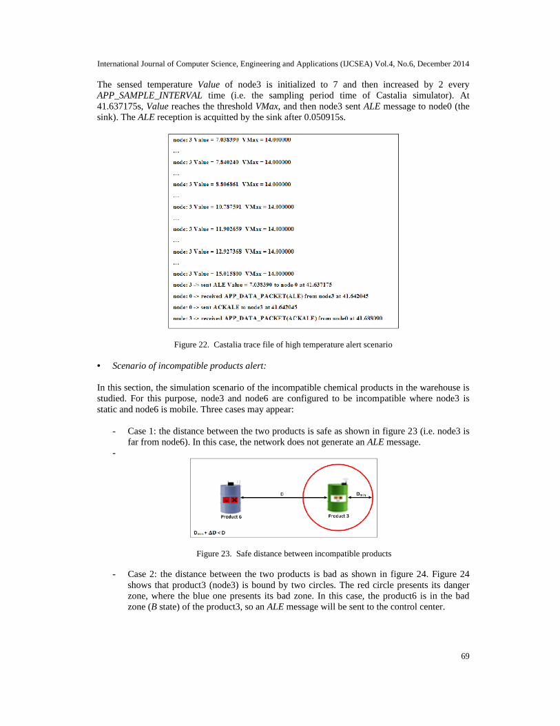
Figure 22 shows the simulation scenario when the internal temperature of some nodes exceeds athreshold called VMax. VMax is fixed to 14 and the node3 is configured in order to exceed thisvalue.
International Journal of Computer Science, Engineering and Applications (IJCSEA) Vol.4, No.6, December 2014
69
The sensed temperature Value of node3 is initialized to 7 and then increased by 2 everyAPP_SAMPLE_INTERVAL time (i.e. the sampling period time of Castalia simulator). At41.637175s, Value reaches the threshold VMax, and then node3 sent ALE message to node0 (thesink). The ALE reception is acquitted by the sink after 0.050915s.
Figure 22. Castalia trace file of high temperature alert scenario
• Scenario of incompatible products alert:
In this section, the simulation scenario of the incompatible chemical products in the warehouse isstudied. For this purpose, node3 and node6 are configured to be incompatible where node3 isstatic and node6 is mobile. Three cases may appear:
- Case 1: the distance between the two products is safe as shown in figure 23 (i.e. node3 isfar from node6). In this case, the network does not generate an ALE message.
-
Figure 23. Safe distance between incompatible products
- Case 2: the distance between the two products is bad as shown in figure 24. Figure 24shows that product3 (node3) is bound by two circles. The red circle presents its dangerzone, where the blue one presents its bad zone. In this case, the product6 is in the badzone (B state) of the product3, so an ALE message will be sent to the control center.

International Journal of Computer Science, Engineering and Applications (IJCSEA) Vol.4, No.6, December 2014
70
Figure 24. Bad distance between incompatible products
- Case 3: the distance between the two products exceeds the threshold Dmin as shown in figure25.
Figure 25. Dangerous distance between incompatible products
Product3 and product6 are very close (the red circle is the dangerous zone of the product3), theirdistance exceeds the threshold Dmin. Thus, ALE message is sent by node3 to the control center(node0). The message exchange for this case is presented in figure 26.
Figure 26. Castalia trace file of incompatible distance alert scenario

International Journal of Computer Science, Engineering and Applications (IJCSEA) Vol.4, No.6, December 2014
71
Upon receiving the GRE message of node3 at 38.853704s, node6 verifies the incompatibilitysecurity level and sends RSI message to node3. Node3 detect danger incompatible state in theinstant t1=38.858001s. Thus, ALE message is sent to node0 (the sink). Node0 received ALE at38.89755 within a delay of 0.043846s.
7. CONCLUSIONS
In this paper, an application and network layers for wireless sensor networks are developed tosupervise dangerous chemical products warehouse using the concept of active product. Twocritical factors are considered, the ambient temperature of chemical product and theirincompatibility. The distance between the incompatible products is supervised to prevent allpossible dangerous reaction. Four security rules are proposed to monitor these factors: static,dynamics, community, and global rules. Then, a supervising application layer is developed toexchange messages between the active product and the control center using differentcommunications step: registration, configuration, internal surveillance, and alert announcement.Finally, network layer is developed for routing the different application message. Differentrouting strategies are proposed for each message class. Node-disjoint multipath routing is used foralert message to provide fault-tolerant and high quality of service. And, information gathering-based routing is used to route the routine messages. Through computer simulation usingCastalia/OMNeT++ tools, the performance of our solution is evaluated and studied. Simulationresults showed that the network layer can achieve short average end to end delay and very lowpacket loss rate for alert messages. In addition, the application layer reacted perfectly for criticalevent (high temperature, incompatible products very close).
REFERENCES
[1] N. Bari, G. Mani, S. Berkovich, (2013) "Internet of Things as a Methodological Concept", 4th IEEEInternational Conference on Computing for Geospatial Research and Application, San Jose CA USA,pp. 48-55.
[2] C. Seitz, T. Runkler, J. Neidig, (2011) "Autonomous product memories for industrial applications",9th IEEE International Conference on Industrial Informatics, Caparica Lisbon Portugal, pp. 175-180.
[3] E. Bajic, (2009) “A Service-Based Methodology for RFID-Smart Objects Interactions in SupplyChain”, International Journal of Multimedia and Ubiquitous Engineering, Vol. 4, No. 3, pp. 37-56.
[4] K. Mekki, W. Derigent, A. Zouinkhi, E. Rondeau, M. N. Abdelkrim, (2013) “Multi-hop CounterBased Data Dissemination Protocol for Communicating Materials”, 9th IEEE InternationalConference on Wireless and Mobile Computing, Networking, and Communications, Lyon France, pp.45-52.
[5] M. Strohbach, G. Kortuem, and H. Gellersen, (2005) “Cooperative artefacts - A framework forembedding knowledge in real world objects”, International Workshop on Smart Object Systems,Tokyo Japan, pp. 91-99.
[6] M. Strohbach, G. Kortuem, H. Gellersen, C. Kray, (2004) “Cooperative artefacts - Assessing realworld situations with embedded technology”, 6th International Conference on Ubiquitous Computing,Nottingham, pp. 250-267.
[7] C. Decker, M. Beigl, A. Eames, U. Kubach, (2004) “Digiclip : Activating physical documents”, 24thInternational Conference on Distributed Computing Systems, Tokyo Japan, pp. 388-393.
[8] D. Liu, K. Law, G. Wiederhold, (2000) “Chaos : An active security mediation system”, InternationalConference on Advanced Information Systems Engineering, Stockholm.
[9] M.S. Hossen, M.K.B. Kamal, M.S. Rahman, (2012) "Consistency analysis of RSSI measurement fordistance estimation of Wireless Sensor nodes", 15th International Conference on Computer andInformation Technology, Chittagong Bangladesh, pp. 290-294.
[10] J. Chen, M. Diaz, L. Llopis, B. Rubio, J.M. Troya, (2011) “A survey on quality of service support inwireless sensor and actor networks: Requirements and challenges in the context of criticalinfrastructure protection”, Journal of Network and Computer Applications, Vol. 34, No. 4, pp. 1225-1239.

International Journal of Computer Science, Engineering and Applications (IJCSEA) Vol.4, No.6, December 2014
72
[11] T. He, J. Stankovic, C. Lu, T. Abdelzaher, (2003) “SPEED: A stateless protocol for real-timecommunication in sensor networks", 23rd International Conference on Distributed ComputingSystems, pp. 46-55.
[12] Z. Che-aron, W. Al-Khateeb, F. Anwar, (2010) “An Enhancement of AODV routing protocol formore robust wireless sensor network”. International Journal of Computer and Network Security, Vol.2, No. 7, pp. 18-26.
[13] O. Chipara, Z. He, G. Xing, Q. Chen, X. Wang, C. Lu, J. Stankovic, T. Abdelzaher, (2006) “Real-time power-aware routing in sensor network”, 14th IEEE International Workshop on Quality ofService, pp. 83-92.
[14] Y. Li, C.S. Chen, Y. Song, Z. Wang, Y. Sun, (2009) “Enhancing Real-Time Delivery in WirelessSensor Networks with Two-Hop Information”, IEEE Transactions on Industrial Informatics, Vol. 5,No. 2, pp. 113-122.
[15] E. Gelenbe, E. Ngai, (2008) “Adaptive QoS Routing for Significant Events in Wireless SensorNetworks”, 5th IEEE International Conference on Mobile AdHoc and Sensor Systems, pp. 410-415.
[16] J. B. Othman, B. Yahya, (2010) “Energy efficient and QoS based routing protocol for wireless sensornetworks”, Journal of Parallel and Distributed Computing, Vol. 70, No. 8, pp. 849-857.
[17] J. Sen, A. Ukil, (2009) “An Adaptable and QoS-Aware Routing Protocol for Wireless SensorNetworks”, 1st International Conference on Wireless Communication, Vehicular Technology,Information Theory and Aerospace & Electronic Systems Technology, Aalborg Denmark, pp. 767-771.
[18] D. Dobre, E. Bajic, (2007) “Smart object design for active security management of hazardousproducts”, 1st International Workshop on Design and Integration Principles for Smart Objects,Innsbruck Austria.
[19] D. Dobre, E. Bajic, (2008) “Active product modeling for chemical security management based onsmart object concept”, 7th International Conference on Modeling and Simulation, Paris France.
[20] K. Mekki, W. Derigent, A. Zouinkhi, E. Rondeau, M.N. Abdelkrim, (2014) “Data DisseminationAlgorithms for Communicating Materials using Wireless Sensor Networks”, The 2nd IEEEInternational Conference on Future Internet of Things and Cloud, Barcelona Spain, pp. 230-237.
[21] A. Nechibvute, A. Chawanda, P. Luhanga, (2012) “Piezoelectric Energy Harvesting Devices: AnAlternative Energy Source for Wireless Sensors”, Journal of Smart Materials Research, pp. 1-13.
[22] B. Musznicki, P. Zwierzykowski, (2012) "Survey of Simulators for Wireless Sensor Networks”,International Journal of Grid and Distributed Computing, Vol. 5, No. 3, pp. 23-50.
[23] T.R. Sheltami, E.M. Shakshuki, H.T. Mouftah, (2009) "Performance evaluation of TELOSB sensornetwork", 7th International Conference on Advances in Mobile Computing and Multimedia, KualaLumpur Malaysia, pp. 584-588.
[24] J.T. Adams, (2006) "An Introduction to IEEE STD 802.15.4", IEEE Aerospace Conference, Big SkyMontana USA.
[25] L. Hey, E. Gelenbe, (2009) “Adaptive Packet Prioritisation for Wireless Sensor Networks”, 5th Euro-NGI Conference on Next Generation Internet Networks, Aveiro, pp. 1-7.