applicat lon of a wireless sensing and control system to ...jerlynch/papers/spie... · applicat lon...
TRANSCRIPT

Application of a wireless sensing and control system to control a torsion-coupling building with MR-dampers
Sung-Chieh Hsua, Kung-Chun Lua, Pei-Yang Linb, Chin-Hsiung Loha, Jerome P. Lynchc
aDepartment of Civil Engineering, National Taiwan University, Taipei, 10617, Taiwan bNational Center for Research on Earthquake Engineering, Taipei, Taiwan
cDept. of Civil & Environmental Eng., University of Michigan, Ann Arbor, MI 48109, USA
ABSTRACT
This study examines the potential use of wireless communication and embedded computing technologies (WiSSCon) within real-time structural control applications. Based on the implementation of the prototype WiSSCon system in a three story steel test structure with significant eccentricity, a centralized control architecture is implemented to mitigate the lateral and torsional response of the test structure using two MR dampers installed in the first story. During the test, a large earthquake time history is applied (El Centro) at the structure base using a shaking table. Three major performance attributes of the wireless control system were examined: (1) validation of the reliability of wireless communications for real-time structural control applications, (2) validation of a modified exponential damper model embedded in the wireless sensors to operate the MR dampers, and (3) exploration of control effectiveness when using WiSSCon in a centralized architectural configuration.
Keywords: Wireless active sensing system, H2-LQG control algorithm, MR-damper
1. INTRODUCTION Active structural control has been successfully applied in many buildings and bridges. Yet, there are a number of challenges that remain. These challenges include: (1) the need to reduce cost and maintenance, (2) reliance on external power, (3) system reliability and robustness, and (4) acceptance by the profession [Dyke et al. 1996]. Semi-active control strategies appear to be particularly promising. For the installation of semi-active control devices in structures, extensive lengths of wires are often needed to connect sensors (to provide real-time state feedback) with a controller where control forces are calculated. To improve the disadvantage of the wired control system, a wireless sensing and control system needs to be developed. With regards to the sensing system, a wireless system could decrease the trouble encountered when monitoring large-scale structures with wired systems [Straser and Kiremidjian, 1998]. Recently, Lynch et al. [2004] extended the wireless monitoring system to include embedded damage identification algorithms. Lynch et al. [2006a] also proposed a closed-loop control strategy with MR dampers using wireless sensor networks. The work opens up the possibility of applying wireless sensor networks to real-time structural control problems. Recently, work on the experimental verification of wireless sensing and control system to control a 3-story symmetric structure using MR-dampers subjected to 1-D earthquake excitation had been conducted by Loh et al. [2007]. The advantages of using wireless sensors for structural sensing and control had been verified using a symmetric building structure in the laboratory. In order to understand the applicability of a wireless control system to control a more complicated dynamic structural response to earthquake excitation, a torsion-coupling building structure has been designed. The potential use of the wireless sensing and control system to control this torsion-coupling building structure is verified herein.
Various semi-active devices have been proposed to generate control forces using viscoelastic-plastic fluids that can dissipate vibration energy in a structural system. For example magnetorheological (MR) dampers are a new class of semi-active control device that uses MR fluids to provide controllable dampers that are quite promising for civil engineering applications [Spencer et al. 1997; Li et al. 2000; Jansen et al. 2000; Jalili et al. 2002]. This paper presents the potential use of wireless communication and embedded computing technologies within real-time structural control applications to control a torsion-coupling steel structure using two MR-dampers installed in the first floor. Then the H2-LQG acceleration feedback control strategy is proposed for controlling the MR-damper. The effectiveness of the
Sensors and Smart Structures Technologies for Civil, Mechanical, and Aerospace Systems 2007,edited by Masayoshi Tomizuka, Chung-Bang Yun, Victor Giurgiutiu, Proc. of SPIE Vol. 6529,
652944, (2007) · 0277-786X/07/$18 · doi: 10.1117/12.711628
Proc. of SPIE Vol. 6529 652944-1

10
10
10
10
10
10
10
3rd Floor - Acceleration)Torsion)
Frequency (Hz)
proposed wireless control algorithms and the usefulness of MR-dampers for the structural response reduction (including torsion-coupling) are demonstrated.
2. EXPERIMENTAL HARDWARE PLACEMENT
2.1 Test Structure
A three-story three dimensional steel-frame structure was designed and constructed at the National Center for Research on Earthquake Engineering (NCREE) in Taipei, Taiwan. The building, as shown in Fig. 1a, consisted of only one bay with a floor area of 3m by 2m and an inter-story height of 3 m. Each column and girder of the structure is selected as a H150×150×7×10 steel I-beam; the beam–column joint consists of a bolted connection. To emulate a real building system, additional mass (a total of 2500 kg per floor) was placed eccentrically on each floor. The structural response under the selected ground excitation (El Centro 1940 NS scaled to 100 gal PGA) was recorded to identify the relative damping and stiffness matrices used to assemble a reduced-order equation of motion. System identification techniques were applied to the seismic response data of the shaking table tests. The reduced-order mathematical model considered, in total, six degrees of freedom (at each floor, there is one translational and one torsional DOF) with the structural’s natural frequencies being 1.30, 2.76, 3.60 (torsion), 6.10, 7.37, and 12.89 Hz (torsion), respectively. Comparison of the 3rd floor frequency response function between the system’s model and experiment are shown in Fig. 1b, indicating good coherence between then two (the numerical model and the actual test structure). The numerical model will be used to calculate the control gain need for closed-loop structural control.
Fig. 1: (a) Schematic diagram of a 3-story frame structure with eccentric mass (2.5 ton of eccentric mass added to each floor); (b) comparison of the 3rd floor frequency response function between experimental and numerical results.
2.2 Control Devices
Two MR dampers were installed within the first level on each side of the frame (along the structural’s weak direction, x-axis). The maximum resisting force capacity of these two dampers are about ± 20 kN and ± 7 kN, respectively. The 7kN damper was placed on the side of the eccentric mass. The bounds of stroke and velocity for the 20 kN damper are approximately equal to 4 cm and 45 cm/sec, respectively, while for the 7kN damper they are approximately 1.5 cm and 15 cm/sec respectively. For simulation purposes, a mathematical model for the MR damper is needed to evaluate the control force. In this study, the mathematical form of the MR-damper is expressed as follows:
xxaaf a && ])([exp 321 −= (1)
where a1, a2 and a3 are voltage dependent parameters, and x& is the shaft velocity of the damper. A series of tests are conducted on both dampers to determine the model parameters. Validation of the MR damper models (20kN and 7kN,
Θ 2
Θ 1x1
x2
Θ 3 x3
Θ 2
Θ 1x1
Θ 1x1
x2x2
Θ 3 x3Θ 3 x3
(a) (b)
Direction ofexcitation
x
y
Proc. of SPIE Vol. 6529 652944-2

Fig. 2: Comparison of the force-displacement and force-velocity relationship of MR-dampers between the performance test data and the numerical simulation: (a) for the case of random displacement and random voltage (20kN MR-damper); (b) for the case of random displacement and random voltage (7kN MR-damper).
respectively) are shown in Fig. 2 for the case of a random displacement applied to the dampers while random voltage values are applied; good agreement is observed in the damper’s force-velocity relationship obtained during testing and simulation. All coefficients of this model (in Eq. 1) depend on the MR-damper’s voltage level, with the driving voltage in this experiment ranging from 0 to 1.2 V.
2.3 Sensing System
Two stand-along sensing systems are included in the structure for this experiment. The first group of sensors are intended to measure the structural responses at each floor which are fed to controllers to calculate the control forces (i.e. acceleration response from each floor). The second group of sensors are installed to measure relative velocity between the ends of each MR-damper. These relative responses (e.g. velocity between two floors) are used to calculate the voltage to be applied to the MR-damper. A prototype system, WiSSCon (Wireless Structural Sensing and Control System), designed for real-time wireless structural sensing and feedback control [Wang et al. 2005 and Lynch et al. 2006] is implemented to control the structure. In the WiSSCon system, wireless communication is used for the feedback of structural response data to wireless sensors serving as the control kernel (i.e. to calculate control solutions based on received data). The wireless sensing unit is responsible for recording the dynamic response of the structure while the wireless control unit receives responses and calculates a control action to be accomplished by the actuators. For the calculation of control forces at each time-step, the wireless sensing unit designated as the control kernel (termed the wireless control unit) utilizes its local embedded computing resources to quickly process sensor data, generate control signals, and apply control commands to structural actuators within the designated time-step duration.
2.4 Experimental setup
The 3-story steel frame structure previously described is selected for testing on the shaking table of NCREE. Two MR dampers are installed in the first floor using invert V-type braces. The stiffness of the bracing was designed with stiffness much larger than the stiffness of each floor. As shown in Fig. 3a, a 7 kN MR-damper is installed close to the side where the eccentric masses are located while a 20 kN MR-damper is installed away from the location of the eccentric masses. As shown in Fig. 3b, sensing units U1 to U3 are in charge of monitoring the acceleration of each floor and broadcasting response data to the sensing and control units U1a and U1b at the base of the building. Actuation boards are connected to both U1a and U1b to allow each wireless sensor to output voltage signals. They wirelessly receive response data from all sensing units to conduct the calculation of control voltages to be applied to the MR-dampers; U1a will control the 20kN MR-damper and U1b unit will control the 7kN MR-damper. To evaluate the performance of the wireless control systems, the El Centro earthquake ground motion, normalized to PGA=200 gal, is the desired input ground motion to be applied by the shaking table. In the microcontroller of wireless sensors U1a and U1b, software is needed: one software
(a) 20kN- Random displacement and voltage (b) 7kN – Random displacement and voltage
Proc. of SPIE Vol. 6529 652944-3

module is the Kalman estimator (to estimate the full state response based on the measured acceleration data) and the other is to calculate the command voltage applied by the actuation unit. On the first floor, the two wireless sensors acting as controller are installed and connected to the two MR-dampers (20kN and 7kN, respectively) via VCCS (voltage to current converter).
The operation of the WiSSCon system can be explained in 5 steps as follows: (Step 1) boot-up the system from both a PC server and the wireless sensors. (Step 2) the server checks all the wireless sensing and control units in the network through the wireless transceiver and reset the clock once the synchronization process is verified. (Step 3) from the embedded code, each wireless control unit broadcasts a beacon to all other units in the network sequentially announcing that a new time step begins. For centralized control, the clock is set at 20 milliseconds for each sensing unit to receive the signal from other units in this study. For centralized control, a total of 60 milliseconds are needed for all units that receive all the signals from other units. An additional 35 milliseconds is reserved for calculating the control force and hence, a total of 95 milliseconds is required to conduct control at each time-setup. This is the reason to set the sampling rate at 10Hz for centralized control. (Step 4 and Step 5) feedback the results to the PC server and exit the control program. Fig. 4a shows the photo of the test structure in NCREE. A close-up picture of the MR-damper in the first floor is also shown in Fig. 4b.
Fig. 3: Schematic diagram detailing the sensing and control system employed in the 3-story structure: (a) installation locations and (b) relationship between U1~U3 (sensors) and U1a and U1b are (controller).
3. CONTROL ALGORITHM Numerous control algorithms, generally based on state-space formulation ( BuAzz +=& ), are used to generate a time-independent control gain with respect to the system’s full state response. Furthermore, the Kalman estimator will be required to estimate the full state response if only limited measurements are provided. In this study, three control approaches (H2-LQG, passive-on and passive-off) are examined and modified from centralized forms into decentralized ones.
3.1 Centralized control of structural system
In developing the fully centralized control algorithm, every control force is dependent on each element of the state vector. Since full-state measurement is impossible and not implementable for realistic structural control, a Kalman estimator is
Direction of excitation
Proc. of SPIE Vol. 6529 652944-4

rM
I tikIITh
Fig. 4: Photo of the test structure; (a) 3-story steel frame on NCREE shaking table, and (b) a close-up view of the damper installation in the first floor.
used to estimate the full state response from the measurement vector. After estimation, the control force is calculated using the time-invariant gain matrix and the state estimate. The objective function of the H2 control algorithm is defined by:
∑=
×× +=1
0kk22
T1212
T ]}[][][][{k
kkkk uRuzQzJ (2)
where Q is a weighting matrix related to the structural system response and R is another weighting matrix related to the control force. z[k] is the state vector defined as { }321321321321 θθθθθθ &&&&&& xxxxxxz = . Through minimization of the objective function, J, the control force can be obtained:
][][)2(][ 122dTd
1d
Td kkk zGzPABPBBRu ×
− =+−= (3)
where G is the control gain matrix. Eq. 3 shows that the control force, u[k], is associated with the full-state vector z[k]. Considering the limited number of sensors installed in the structure, a Kalman estimator transforms response measurements into an estimate of the full-state vector.
To minimize computation time, a voltage-velocity-command force relationship is pre-embedded in the microcontroller of the wireless sensors interfaced to the MR-dampers. To embed the control surface into the microcontroller, as shown in Fig. 5, it is necessary to discretize the control surface so that the control voltage can be obtained from the measured damper velocity and the desired control force (also calculated by the microcontroller). Thirteen levels of voltage (between 0 and 1.2 V) are pre-assigned; based on the measured velocity and the calculated command force, the voltage for the MR-damper can be roughly estimated and sent to the VCCS to convert the voltage into an equivalent current used to attain the MR-damper damping coefficient. Fig.6 shows the computation embedded in the WiSSCon system. In this study three different control strategies are considered: (1) Passive-off case: the voltage of the two MR-dampers are both set to 0 V;
Proc. of SPIE Vol. 6529 652944-5

Fig. 5: Embedded control force-damper velocity-command voltage relationship in the wireless sensing and control unit
for: (a) 20kN MR-damper, and (b) 7kN MR-damper
Fig. 6: Embedded computation algorithm in the microcontroller of the WiSSCon systems and control kernel.
Fig. 7: Comparison of the command voltage between the recorded wired system (NCREE data acquisition system) and wireless monitoring and sensing system.
(a) (b)
For 20kN MR-damper For 7kN MR-damper
to VCCS then feed the current
to MR-damper From response Measurements
From the measurement of the damper stroke velocity
U[k]
V[k] Y[k]
Y[k]
Z[k]
Proc. of SPIE Vol. 6529 652944-6
UI, II]
10 20 30 flO 50 60 ZOrI(s.)
10 20 30 flO 50 60Thime(Sec.)
(2) Passive-on case: the voltage of the two MR-dampers are both set to 1.2 V; (3) H2-LQG centralized control using the WiSSCon system.
Due to the limitation of the wireless communication in the WiSSCon system the sampling rate for applying voltage command signals to the MR dampers is set at 10 Hz.
3.2 Validation on wireless communication
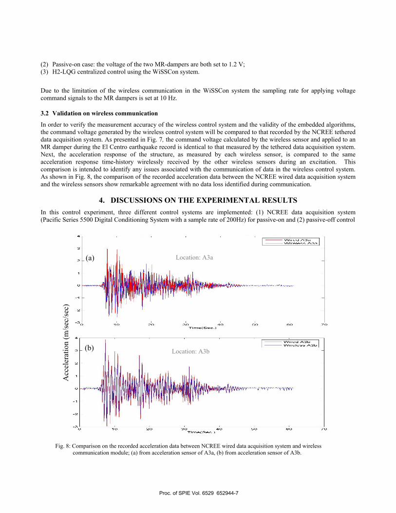
In order to verify the measurement accuracy of the wireless control system and the validity of the embedded algorithms, the command voltage generated by the wireless control system will be compared to that recorded by the NCREE tethered data acquisition system. As presented in Fig. 7, the command voltage calculated by the wireless sensor and applied to an MR damper during the El Centro earthquake record is identical to that measured by the tethered data acquisition system. Next, the acceleration response of the structure, as measured by each wireless sensor, is compared to the same acceleration response time-history wirelessly received by the other wireless sensors during an excitation. This comparison is intended to identify any issues associated with the communication of data in the wireless control system. As shown in Fig. 8, the comparison of the recorded acceleration data between the NCREE wired data acquisition system and the wireless sensors show remarkable agreement with no data loss identified during communication.
4. DISCUSSIONS ON THE EXPERIMENTAL RESULTS In this control experiment, three different control systems are implemented: (1) NCREE data acquisition system (Pacific Series 5500 Digital Conditioning System with a sample rate of 200Hz) for passive-on and (2) passive-off control
Fig. 8: Comparison on the recorded acceleration data between NCREE wired data acquisition system and wireless communication module; (a) from acceleration sensor of A3a, (b) from acceleration sensor of A3b.
Location: A3a (a)
Location: A3b
Acc
eler
atio
n (m
/sec
/sec
)
(b)
Proc. of SPIE Vol. 6529 652944-7
2:
Time(sec)
W1CenH2-EL-200
W1CenH2-EL-200
>
>0.5
cvi
I I II0 15 2 5 40 45
Time(sec)
WiCenH2-EL-200
Fdl
5 10 15 20 25 30 35 40 45 50Time (sec)
WiCenH2-EL-200
Fd2
5 10 15 20 25 30 35 40 45 50Time (sec)
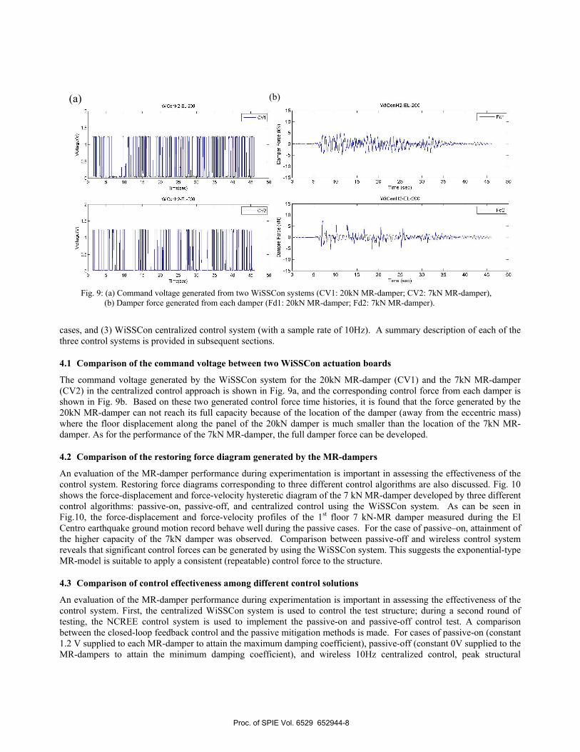
Fig. 9: (a) Command voltage generated from two WiSSCon systems (CV1: 20kN MR-damper; CV2: 7kN MR-damper), (b) Damper force generated from each damper (Fd1: 20kN MR-damper; Fd2: 7kN MR-damper).
cases, and (3) WiSSCon centralized control system (with a sample rate of 10Hz). A summary description of each of the three control systems is provided in subsequent sections.
4.1 Comparison of the command voltage between two WiSSCon actuation boards
The command voltage generated by the WiSSCon system for the 20kN MR-damper (CV1) and the 7kN MR-damper (CV2) in the centralized control approach is shown in Fig. 9a, and the corresponding control force from each damper is shown in Fig. 9b. Based on these two generated control force time histories, it is found that the force generated by the 20kN MR-damper can not reach its full capacity because of the location of the damper (away from the eccentric mass) where the floor displacement along the panel of the 20kN damper is much smaller than the location of the 7kN MR-damper. As for the performance of the 7kN MR-damper, the full damper force can be developed.
4.2 Comparison of the restoring force diagram generated by the MR-dampers
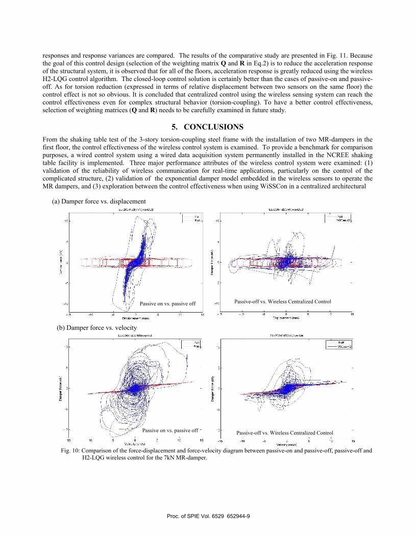
An evaluation of the MR-damper performance during experimentation is important in assessing the effectiveness of the control system. Restoring force diagrams corresponding to three different control algorithms are also discussed. Fig. 10 shows the force-displacement and force-velocity hysteretic diagram of the 7 kN MR-damper developed by three different control algorithms: passive-on, passive-off, and centralized control using the WiSSCon system. As can be seen in Fig.10, the force-displacement and force-velocity profiles of the 1st floor 7 kN-MR damper measured during the El Centro earthquake ground motion record behave well during the passive cases. For the case of passive–on, attainment of the higher capacity of the 7kN damper was observed. Comparison between passive-off and wireless control system reveals that significant control forces can be generated by using the WiSSCon system. This suggests the exponential-type MR-model is suitable to apply a consistent (repeatable) control force to the structure.
4.3 Comparison of control effectiveness among different control solutions
An evaluation of the MR-damper performance during experimentation is important in assessing the effectiveness of the control system. First, the centralized WiSSCon system is used to control the test structure; during a second round of testing, the NCREE control system is used to implement the passive-on and passive-off control test. A comparison between the closed-loop feedback control and the passive mitigation methods is made. For cases of passive-on (constant 1.2 V supplied to each MR-damper to attain the maximum damping coefficient), passive-off (constant 0V supplied to the MR-dampers to attain the minimum damping coefficient), and wireless 10Hz centralized control, peak structural
(a) (b)
Proc. of SPIE Vol. 6529 652944-8
P000
EL-200-Fd2)7kN)-vs-Dd2
-15 -10 -5Displaceroent (roro)
10 15
EL-200-Fd2(7kN)-vs-Dd2
-15 -10 -5 0Displaceroeot (ooo)
PollW1CeoH2
10 15
Dam
per
For
ce (
kN)
EL-200-Fd2)7kN)-vs-Vel
PoffWiCenH2
-15 -10 -5 0 5 10 15Velocity (crc/c)
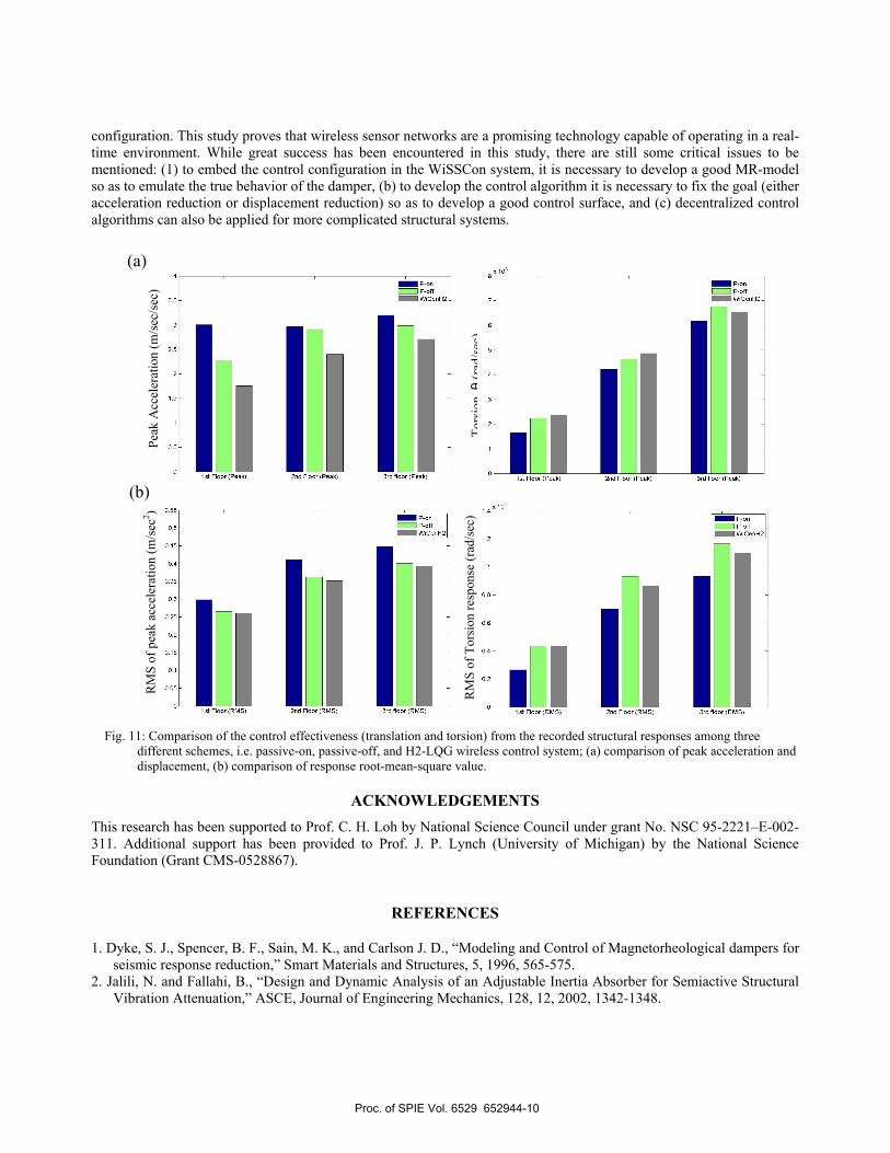
responses and response variances are compared. The results of the comparative study are presented in Fig. 11. Because the goal of this control design (selection of the weighting matrix Q and R in Eq.2) is to reduce the acceleration response of the structural system, it is observed that for all of the floors, acceleration response is greatly reduced using the wireless H2-LQG control algorithm. The closed-loop control solution is certainly better than the cases of passive-on and passive-off. As for torsion reduction (expressed in terms of relative displacement between two sensors on the same floor) the control effect is not so obvious. It is concluded that centralized control using the wireless sensing system can reach the control effectiveness even for complex structural behavior (torsion-coupling). To have a better control effectiveness, selection of weighting matrices (Q and R) needs to be carefully examined in future study.
5. CONCLUSIONS From the shaking table test of the 3-story torsion-coupling steel frame with the installation of two MR-dampers in the first floor, the control effectiveness of the wireless control system is examined. To provide a benchmark for comparison purposes, a wired control system using a wired data acquisition system permanently installed in the NCREE shaking table facility is implemented. Three major performance attributes of the wireless control system were examined: (1) validation of the reliability of wireless communication for real-time applications, particularly on the control of the complicated structure, (2) validation of the exponential damper model embedded in the wireless sensors to operate the MR dampers, and (3) exploration between the control effectiveness when using WiSSCon in a centralized architectural
Fig. 10: Comparison of the force-displacement and force-velocity diagram between passive-on and passive-off, passive-off and H2-LQG wireless control for the 7kN MR-damper.
(a) Damper force vs. displacement
(b) Damper force vs. velocity
Passive-off vs. Wireless Centralized Control
Passive-off vs. Wireless Centralized Control
Passive on vs. passive off
Passive on vs. passive off
Proc. of SPIE Vol. 6529 652944-9
3.5
2.5
— P-onP-offW1CenH2
1st Floor (Peak) 2nd Floor (Peak) 3rd floor (Peak).n I I
— P-onP-off
JW1CenH2
1st Floor (Peak) 2nd Floor (Peak) 3rd floor (Peak)
— P-onP-offW1CenH2
0.55
0.5
0.45
0.4
0.35
0.3
0.25
0.2
— P-orP-off
WiCerH2
lot Floor (RMS) 2nd Floor (RMS) 3rd floor (RMS)
configuration. This study proves that wireless sensor networks are a promising technology capable of operating in a real-time environment. While great success has been encountered in this study, there are still some critical issues to be mentioned: (1) to embed the control configuration in the WiSSCon system, it is necessary to develop a good MR-model so as to emulate the true behavior of the damper, (b) to develop the control algorithm it is necessary to fix the goal (either acceleration reduction or displacement reduction) so as to develop a good control surface, and (c) decentralized control algorithms can also be applied for more complicated structural systems.
Fig. 11: Comparison of the control effectiveness (translation and torsion) from the recorded structural responses among three different schemes, i.e. passive-on, passive-off, and H2-LQG wireless control system; (a) comparison of peak acceleration and displacement, (b) comparison of response root-mean-square value.
ACKNOWLEDGEMENTS This research has been supported to Prof. C. H. Loh by National Science Council under grant No. NSC 95-2221–E-002-311. Additional support has been provided to Prof. J. P. Lynch (University of Michigan) by the National Science Foundation (Grant CMS-0528867).
REFERENCES
1. Dyke, S. J., Spencer, B. F., Sain, M. K., and Carlson J. D., “Modeling and Control of Magnetorheological dampers for seismic response reduction,” Smart Materials and Structures, 5, 1996, 565-575.
2. Jalili, N. and Fallahi, B., “Design and Dynamic Analysis of an Adjustable Inertia Absorber for Semiactive Structural Vibration Attenuation,” ASCE, Journal of Engineering Mechanics, 128, 12, 2002, 1342-1348.
(a)
Peak
Acc
eler
atio
n (m
/sec
/sec
)
Tors
ionθ
(rad
/sec
)(b)
RM
S of
pea
k ac
cele
ratio
n (m
/sec
2 )
RM
S of
Tor
sion
resp
onse
(rad
/sec
)
Proc. of SPIE Vol. 6529 652944-10
3. Jansen, L. M. and Dyke, S. J., “Semi-active control strategies for MR dampers: a comparative study,” ASCE, Journal of Engineering Mechanics, 126, 8, 2000, 795-803.
4. Li, W. H., Yao, G. Z., Chen, G., Yeo, S. H., and Yap, F. F.,” Testing and steady state modeling of a linear MR damper under sinusoidal loading,” Smart Materials and Structures, 9, 2000, 95-102.
5. Loh, C.H., Lynch, J.P., Lu, K.C., Wang, Y., Chang, C.M., Lin, P.Y., and Yeh, T. H., “Experimental verification of wireless sensing and control system for structural control using MR-dampers,” Earthquake Engineering and Structural Dynamics, (in printing) 2007.
6. Lynch, J. P. and Law, K. H., “Decentralized control techniques for large-scale civil structural systems,” Proceedings of the 20th International Modal Analysis Conference, 2002.
7. Lynch, J. P., Wang, Y., Lu, K. C., Hou, T. C., and Loh, C. H., “Post-seismic Damage Assessment of Steel Structures Instrumented with Self-interrogating Wireless Sensors,” Proceedings of the 8th National Conference on Earthquake Engineering, San Francisco, CA, USA, April 18-22, 2006a.
8. Lynch, J. P., Wang, Y., Swartz, R. A., Lu, K. C., and Loh, C. H., “Implementation of a close-loop structural control system using wireless sensor networks,” submitted to J. of Structural Control and Health Monitoring, 2006b.
9. Schurter, K. C. and Roschke, P. N., “Neuro-fuzzy control of structures using acceleration feedback,” Smart Materials and Structures, 10, 2001, 770-779
10. Spencer, B. F., Dyke, S. J., Sain, M. K., and Carlson, J. D., “Phenomenological Model for Magnetorheological Dampers,” ASCE, Journal of Engineering Mechanics, 123, 3, 1997, 230-238.
11. Straser, E. G. and Kiremidjian, A. S., “A modular, wireless damage monitoring system for structures,” Report No. 129, John A. Blume Earthquake Engineering Research Center, Department of Civil and Environmental Engineering, Stanford University, CA 1998.
12. Wang, Y., Lynch, L. P., Law, K. H., “Design of a low-power wireless structural monitoring system for collaborative computational algorithms,” Proceedings of SPIE 10th annual Int. Symposium on Nondestructive Evaluation for Health Monitoring and Diagnostics, San Diego, CA, March 6-10, 2005.
Proc. of SPIE Vol. 6529 652944-11