applicability of composite charpy impact … · strain hardening textile reinforced ... of an ipc...
TRANSCRIPT

Page 0
APPLICABILITY OF COMPOSITE CHARPY IMPACT METHOD FORSTRAIN HARDENING TEXTILE REINFORCED CEMENTITIOUSCOMPOSITES
J. Van Ackeren (1), J. Blom (1), D. Kakogiannis (1), J. Wastiels (1), D. Van Hemelrijck (1), S.Palanivelu (2), W. Van Paepegem (2), J. Vantomme (3)
(1) Vrije Universiteit Brussel, Mechanics of Materials and Constructions, Brussels, Belgium
(2) Universiteit Gent, Dept. of Materials Science and Engineering, Gent, Belgium
(3) Royal Military Academy, Civil and Materials Engineering Department, Brussels, Belgium
Abstract ID Number: 20
Author contacts
Authors E-Mail Fax Postal address
J. Van Ackeren [email protected]+3226292928
Pleinlaan 2, B-1050Brussels
J. Blom [email protected] 2, B-1050Brussels
D.Kakogiannis
[email protected] 2, B-1050Brussels
J. Wastiels [email protected] 2, B-1050Brussels
D. VanHemelrijck
[email protected] 2, B-1050Brussels
S. Palanivelu [email protected] 419000 Gent, Belgium
W. VanPaepegem
[email protected] 419000 Gent, Belgium
J. Vantomme [email protected] av. de la RenaissanceB-1000 Brussels, Belgium
Contact person for the paper: J. Van Ackeren
Presenter of the paper during the Conference: J. Van Ackeren
9
Total number of pages of the paper (this one excluded): 8

Page 1
APPLICABILITY OF COMPOSITE CHARPY IMPACT METHOD FORSTRAIN HARDENING TEXTILE REINFORCED CEMENTITIOUSCOMPOSITES
J. Van Ackeren (1), J. Blom (1), D. Kakogiannis (1), J. Wastiels (1), D. Van Hemelrijck (1), S.Palanivelu (2), W. Van Paepegem (2), J. Vantomme (3)
(1) Vrije Universiteit Brussel, Mechanics of Materials and Constructions, Brussels, Belgium
(2) Universiteit Gent, Dept. of Materials Science and Engineering, Gent, Belgium
(3) Royal Military Academy, Civil and Materials Engineering Department, Brussels, Belgium
AbstractSince most test methods, used for strain hardening cementitious composites, are adopted
from polymer composites test standards, this paper investigates the applicability of a standardimpact test (ISO 179-1:2000), which is used in the polymer composites world, on a specifictextile reinforced cementitious composite using an inorganic phosphate cement (IPC) as amatrix material. The aim is to provide a test method to investigate the local impact behaviourof textile reinforced cementitious composites. It was found within this work that this methodis applicable to cementitious composites provided some adaptations to the specimens’dimensions. The Charpy impact strength of an IPC matrix reinforced with different kinds offibre types is successfully investigated. This test method can be used to qualitatively rankdifferent cementitious composite materials.
1. INTRODUCTIONIn the last few decades, many new cementitious materials were developed in order to reach
thinner and stronger construction elements. The evolution started with the introduction ofloose steel or polymeric fibres into the fresh concrete mixture, leading to fibre reinforcedconcrete (FRC): the addition of fibres into concrete provides toughness or energy absorptioncapacity to the inherently brittle concrete. A new generation of FRC’s are the so called textilereinforced concretes (TRC) in which mainly fibre textiles (glass, polymers …) are applied asreinforcement: they can provide also a strain hardening capacity when a sufficiently highquantity of fibres is used. In a recently held conference on these kinds of materials [1], thepotential of these new composites was again demonstrated. In an attempt to better define highperformance fibre reinforced cementitious composites (HPFRCC), Naaman and Reinhardt [2]proposed a clear classification of these materials according to their possibility to exhibit strainhardening under bending or in tension. Within this classification a distinction is madebetween the four following categories: (1) crack control, (2) deflection hardening, (3) strainhardening and (4) high energy absorption.

Page 2
Strain hardening cementitious composites (SHCC) not only show strain hardening undertensile loading, but also can absorb a large amount of energy. The cementitious materialstudied in this paper can most certainly be classified in the fourth category. It exists of aninorganic phosphate cement (IPC) matrix with different kinds of textile reinforcements. IPCwas developed at the Vrije Universiteit Brussel and consists of a liquid component based onphosphoric acid solution containing inorganic metal oxides and a calcium silicate powdercomponent. Next to the advantages of being incombustible (EN13501-1), this material alsopossesses a neutral pH after hardening, which allows cheap E-glass fibres to be used asreinforcement. It is however also possible to process other types of fibres, such as polymericfibres or carbon fibres, into this cementitious matrix. Figure 1 shows typical tensile stress-strain behaviour of IPC composites with different kinds of fibre reinforcements. The fibrevolume fraction is kept constant for all materials at about 20 %. It is clear from this figure thatindeed all tested composite specimens can absorb a significant amount of energy due to theirpronounced strain hardening behaviour after multiple matrix cracking. Note that depending onthe used fibre reinforcement one can obtain a completely different composite material. Forinstance the curve of PE-reinforced IPC shows stiff and strong (up to 400 MPa) behaviour,while on the right side of the graph the PVA reinforced IPC shows ductile (maximum strainmore than 5 %) but less strong behaviour.
0
50
100
150
200
250
300
350
400
450
0 1 2 3 4 5 6
strain [%]
stre
ss[M
Pa]
Carbon
PE
basalt
E-glass (1)
E-glass (2)
PVA
Figure 1: tensile stress-strain behaviour of IPC reinforced with different UD-fibres
This composite material has been investigated in a project that studied the possibility ofproducing sandwich structures that are able to absorb a significant amount of energy underblast or impact loading. The textile reinforced IPC was meant to protect the energy absorbingcore against fire and to distribute the load from the explosion to the sandwich core [3].Apparently, the material itself is able to absorb energy under blast and impact loading withoutfailing. Under impact loading only local damage can cause failure of the material. Globally,there will be matrix cracking reducing the stiffness, but the material keeps its load bearingcapacity. In this paper, the local impact damage and the corresponding energy absorption areinvestigated by means of impact tests.

Page 3
2. CHARPY IMPACT TESTMany test methods for SHCC – like tensile testing - are adopted from, or inspired by the
polymer composites world, rather than the concrete world. Another example is the bendingtest: the scale of the specimen dimensions of a bending test for SHCC is much smaller thanthat for concrete or FRC beams. In order to study the local impact behaviour and thecorresponding energy that can be absorbed, a suitable test method needs to be selected. Themost common test methods concerning impact on composites are either drop weight tests orpendulum tests. In drop weight tests global and local impact behaviour can be investigated ina quantitative way. The Charpy pendulum impact test was initially designed to test the localenergy absorption capacity of metals under three point bending. Adaptations of the machine’scapacity and the specimen dimensions have led to the development of Charpy impact tests forother materials. In the 1980’s and 1990’s Charpy impact tests were developed for FRCcomposites [4]. The specified specimen dimensions are however not applicable for thin TRCmaterials. For plastics and polymer composite materials a standard test method has also beendeveloped (ISO 179-1: Plastics – Determination of Charpy impact properties – Part 1: Non-instrumented test) [5]. It is clearly stated in this standard that the method should not be used toobtain design data. The purpose of the Charpy test is to provide a comparative test to evaluatethe local impact energy absorption of different materials. The principle of the test is illustratedin figure 2 on the left. A specimen is simply supported on both sides and is impacted by asingle blow of a pendulum striker. The absorbed energy is determined by calculating thedifference in potential energy of the pendulum before and after impact. The reported Charpyimpact strength is defined as this energy divided by the mid section area. There are differentpossible testing directions: the specimen can be tested flatwise or edgewise (see figure 2,right) and normal or parallel to the lamina. All specimens tested in this work are tested innormal flatwise direction. Furthermore a distinction is made between materials exhibitinginterlaminar shear (ILS) and those not exhibiting this fracture mode. Similar to fracturemechanics theory the specimens can be notched. In case of cementitious composites it ishowever not necessary to notch the specimens since the material already contains microscopicflaws that will initiate failure. Moreover the fibres inside the material will be severelydamaged by the notch.
Figure 2: left: Charpy impact test; right: different test configurations [5]
The Charpy impact strength can be compared to typical values for toughness that is definedin fracture mechanics as being the energy that is necessary for the growth of a crack.
edgewise flatwise
Page 4
Toughness (Gc) is a material parameter, typical value for different materials can be found inAshby and Jones [6]. For metals, values between 100 and 1000 kJ/m² are given while for mostplastics the toughness is less than 10 kJ/m². Typical values for composites start at 5 kJ/m² andcan reach more than 100 kJ/m².
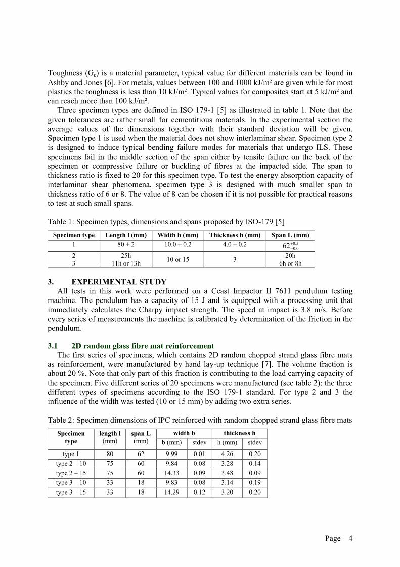
Three specimen types are defined in ISO 179-1 [5] as illustrated in table 1. Note that thegiven tolerances are rather small for cementitious materials. In the experimental section theaverage values of the dimensions together with their standard deviation will be given.Specimen type 1 is used when the material does not show interlaminar shear. Specimen type 2is designed to induce typical bending failure modes for materials that undergo ILS. Thesespecimens fail in the middle section of the span either by tensile failure on the back of thespecimen or compressive failure or buckling of fibres at the impacted side. The span tothickness ratio is fixed to 20 for this specimen type. To test the energy absorption capacity ofinterlaminar shear phenomena, specimen type 3 is designed with much smaller span tothickness ratio of 6 or 8. The value of 8 can be chosen if it is not possible for practical reasonsto test at such small spans.
Table 1: Specimen types, dimensions and spans proposed by ISO-179 [5]
Specimen type Length l (mm) Width b (mm) Thickness h (mm) Span L (mm)
1 80 ± 2 10.0 ± 0.2 4.0 ± 0.2
23
25h11h or 13h
10 or 15 320h
6h or 8h
3. EXPERIMENTAL STUDYAll tests in this work were performed on a Ceast Impactor II 7611 pendulum testing
machine. The pendulum has a capacity of 15 J and is equipped with a processing unit thatimmediately calculates the Charpy impact strength. The speed at impact is 3.8 m/s. Beforeevery series of measurements the machine is calibrated by determination of the friction in thependulum.
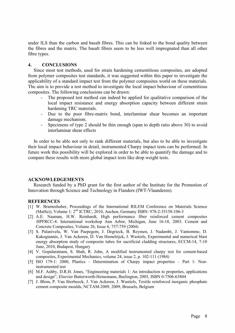
3.1 2D random glass fibre mat reinforcementThe first series of specimens, which contains 2D random chopped strand glass fibre mats
as reinforcement, were manufactured by hand lay-up technique [7]. The volume fraction isabout 20 %. Note that only part of this fraction is contributing to the load carrying capacity ofthe specimen. Five different series of 20 specimens were manufactured (see table 2): the threedifferent types of specimens according to the ISO 179-1 standard. For type 2 and 3 theinfluence of the width was tested (10 or 15 mm) by adding two extra series.
Table 2: Specimen dimensions of IPC reinforced with random chopped strand glass fibre mats
width b thickness hSpecimentype
length l(mm)
span L(mm) b (mm) stdev h (mm) stdev
type 1 80 62 9.99 0.01 4.26 0.20
type 2 – 10 75 60 9.84 0.08 3.28 0.14
type 2 – 15 75 60 14.33 0.09 3.48 0.09
type 3 – 10 33 18 9.83 0.08 3.14 0.19
type 3 – 15 33 18 14.29 0.12 3.20 0.20
5.00.062

Page 5
The results of these tests are made visible in figure 3 in form of boxplots. The the bold linein the middle of the grey box represents the median. Next to the boxplots, a figure shows thetested specimens and their failure modes.
In figure 3 (right) it is clear that indeed the different specimen types cause different failuretypes and consequently variant Charpy impact strength results. Type 1 and 2 specimensmainly fail through compression and tension (in a minor way) in the middle section. Thisbending failure mode is however combined with a small area of interlaminar shear for aspecimen of type 1 (see figure 3), which explains the higher absorbed energy for thesespecimens (43.5 kJ/m²) compared to type 2 specimens (27 kJ/m²). Interlaminar shear is afailure phenomenon which absorbs more energy compared to a pure bending type of failuredue to the larger free surface area that is created. Although these specimens all fail under ILSor multiple shear, there is a lot of scatter on the results of type 3 specimens. Values of almost50 kJ/m² up to 120 kJ/m² were observed. This specimen type might therefore not beapplicable for this kind of random fibre reinforced cementitious material. A possibleexplanation for this is that the specimen dimensions exceed the longitudinal dimension of thefibre bundles. This means that fibre bundles were cut and thus damaged during production.Finally the effect of the specimen width was investigated: mean values of specimens with awidth of 15 mm seem to be slightly higher, but due to the large scatter these differences arenot significant (figure 3, left).
Figure 3: left: boxplots of test results, right: tested specimens, different failure types
For comparison with these results two other matrix materials are impregnated in therandom fibre reinforcements. The applied matrices are a very fine grained cement mortar witha maximum grain size of 0.6 mm and an epoxy resin used in laminating applications for windenergy and boat building (EPIKOTE Resin L 135 and EPIKURE Curing Agent H 134 fromHexion). The cement mortar consists of quartz (713.6 g), quartz powder (499.5 g), cement(490.0 g), water (245.0 g), fly ash (175.0 g), silica-fume (70.0 g) and super plastifier (10.5 g).
Only results of specimens of type 1 are given, since it was found that both materials do notshow interlaminar shear failure. The specimens containing mortar are too brittle causing acomplete break of their middle section (figure 4, left). The average Charpy impact strength often impacted specimens was found to be 9.67 kJ/m² with a standard deviation of 1.84 kJ/m².The epoxy specimens on the other hand show a much larger energy absorption capacity. The
ILS

Page 6
average of ten tests is 93.54 kJ/m² with a standard deviation of 13.8 kJ/m². All specimensseem to fail on the tensile side of the specimens (see figure 4, right). There are two reasons forthis much higher energy absorption capacity: epoxy resin has a much better bond with thefibres and shows a large strain to failure. For comparison: the elongation at break is around0.02 % for mortar and IPC while it is 7 to 10 % for the epoxy resin. Tensile failure will occurat the back of the specimens and thus larger strain energy levels are reached. The secondcause for higher energy absorption is the high flexural strength of the epoxy resin compared tothe mortar or the IPC. The flexural strength of the mortar and the IPC is about 10 MPa whilethat of the epoxy resin is 110 to 130 MPa. Although the energy absorption of the IPCspecimen is smaller than that of polymer composite materials, it absorbs more energy than canbe derived from the properties of the matrix material itself.
Figure 4: impacted specimens with mortar matrix (left) and epoxy matrix (right)
3.2 Unidirectional reinforcementThe aim of this section is to validate this standard test method for IPC specimens with
different kinds of fibre types as reinforcement. In order to be comparable the specimensshould contain the same amount of fibres. The fibre volume fraction (approximately 20 %)could be well controlled by using a self-made pultrusion set-up to impregnate the fibrebundles. Once impregnated, the bundles were put straight in a mould which is pressedtogether. Specimens are then cured for 24h at room temperature and post-cured for another24h at 60°C. The different fibre types with their properties can be found in table 3. Glass fibrerovings are manufactured by Owens Corning, basalt fibres are from Basaltex, carbon fromTOHO, PVA from Nordifa and PE from DSM.
Table 3: different fibre types with their properties
fibre type density (kg/m³) tex (g/km) strength (MPa) stiffness (GPa)glass SE-12001 2600 600 950 75glass SE-15002 2600 600 950 75basalt 2700 1600 1100 78carbon 1800 250 1275 170PVA 1300 250 1000 33PE 975 176 1870 105
1 straight fibre bundles, 2 twisted fibre bundles
Since specimens made with IPC and UD glass fibres, all showed ILS, it was decided to testboth specimen types 2 and 3 for all fibre types. The first series of tests are type 2 tests withnominal dimensions of 10mm x 3mm x 75mm with a span of 60 mm. Specimens werehowever, due to manufacturing, averagely 3.3 mm thick, which lowered the span to thickness

Page 7
ratio to 18 in stead of 20. In more than 65 % of the tested specimens, interlaminar shear wasobserved (figure 5). This is probably due to the relative weak bond between fibres and matrix.
Figure 5: observed ILS failure in type 2 specimens
To tackle this problem the following solution was found: to encourage a bending type offailure, the ratio span to thickness should be increased. This was obtained by decreasing thenominal thickness of the specimens to 2 mm, while the span is kept constant at 60 mm. Thetheoretical span to thickness ratio now becomes 60/2 = 30. The manufactured specimens forthis series had an average thickness of 2.2 mm, which lowers this ratio to 27.3. These adaptedspecimens all failed in the middle section under bending. The obtained values for the Charpyimpact strength are shown in Figure 6 (left). Due to scatter, the differences between themedian values are not significant except for the glass fibres SE-1200. This could be expectedfrom visual inspection of the tested specimens. All specimens failed under bending at thecompressive side of the specimen, which is more related to the matrix material than to theused fibre reinforcement. In order to increase the energy absorption of these materials thebond between fibres and matrix should be increased. Local reinforcement at the impact pointcan also improve the performance of these materials.
Figure 6: results of adapted specimens of type 2 (left) and specimens of type 3 (right)
The last series of tests are performed on type 3 specimens. The average thickness of thespecimens is around 3.3 mm with a standard deviation of 0.1 mm. This results in a specimenlength of 43 mm and a span of 26.4 mm according to table 1. The results are shown in theright hand graph of figure 6. The specimens all failed under ILS as can be seen in the examplein figure 6 (right). In this study the specific used polymer and glass fibres absorb more energy
Page 8
under ILS than the carbon and basalt fibres. This can be linked to the bond quality betweenthe fibres and the matrix. The basalt fibres seem to be less well impregnated than all otherfibre types.
4. CONCLUSIONSSince most test methods, used for strain hardening cementitious composites, are adopted
from polymer composites test standards, it was suggested within this paper to investigate theapplicability of a standard impact test from the polymer composites world on these materials.The aim is to provide a test method to investigate the local impact behaviour of cementitiouscomposites. The following conclusions can be drawn:
- The proposed test method can indeed be applied for qualitative comparison of thelocal impact resistance and energy absorption capacity between different strainhardening TRC materials.
- Due to the poor fibre-matrix bond, interlaminar shear becomes an importantdamage mechanism.
- Specimens of type 2 should be thin enough (span to depth ratio above 30) to avoidinterlaminar shear effects
In order to be able not only to rank different materials, but also to be able to investigatetheir local impact behaviour in detail, instrumented Charpy impact tests can be performed. Infuture work this possibility will be explored in order to be able to quantify the damage and tocompare these results with more global impact tests like drop weight tests.
ACKNOWLEDGEMENTSResearch funded by a PhD grant for the first author of the Institute for the Promotion of
Innovation through Science and Technology in Flanders (IWT-Vlaanderen).
REFERENCES[1] W. Brameshuber, Proceedings of the International RILEM Conference on Materials Science
(MatSci), Volume 1: 2nd ICTRC, 2010, Aachen, Germany ISBN: 978-2-35158-106-3[2] A.E. Naaman, H.W. Reinhardt, High performance fiber reinforced cement composites
HPFRCC-4: International workshop Ann Arbor, Michigan, June 16-18, 2003. Cement andConcrete Composites, Volume 26, Issue 6, 757-759 (2004)
[3] S. Palanivelu, W. Van Paepegem, J. Degrieck, B. Reymen, J. Nadambi, J. Vantomme, D.Kakogiannis, J. Van Ackeren, D. Van Hemelrijck, J. Wastiels, Experimental and numerical blastenergy absorption study of composite tubes for sacrificial cladding structures, ECCM-14, 7-10June, 2010, Budapest, Hungary
[4] V. Gopalaratnam, S. Shah, R. John, A modified instrumented charpy test for cement-basedcomposites, Experimental Mechanics, volume 24, issue 2, p. 102-111 (1984)
[5] ISO 179-1: 2000, Plastics – Determination of Charpy impact properties – Part 1: Non-instrumented test
[6] M.F. Ashby, D.R.H. Jones, “Engineering materials 1: An introduction to properties, applicationsand design”, Elsevier Butterworth-Heinemann, Burlington, 2005, ISBN 0-7506-63804
[7] J. Blom, P. Van Itterbeeck, J. Van Ackeren, J. Wastiels, Textile reinforced inorganic phosphatecement composite moulds, NCTAM-2009, 2009, Brussels, Belgium