applicability & effectivity effective for all systems
TRANSCRIPT

Driver Version: 1.03 Document Revision: 1
A Sierra Monitor Company
APPLICABILITY & EFFECTIVITY
Effective for all systems manufactured after December 2012
Driver Manual (Supplement to the FieldServer Instruction Manual)
FS-8700-138 DNP3 Serial

FS-8700-138 DNP3 Serial Manual Table of Contents
FieldServer Technologies 1991 Tarob Court Milpitas, California 95035 USA Web: www.fieldserver.com Tel: (408) 262 2299 Fax: (408) 262 2269 Toll Free: (888) 509 1970 email: [email protected]
TABLE OF CONTENTS
DNP3 Serial Description ................................................................................................................................. 3 1
Driver Scope of Supply ................................................................................................................................... 4 2
2.1 Supplied by FieldServer Technologies for this driver ..................................................................................... 4 2.2 Provided by the Supplier of 3
rd Party Equipment .......................................................................................... 4
2.2.1 Required 3rd
Party Configuration ........................................................................................................... 4
Hardware Connections ................................................................................................................................... 5 3
3.1 Connection Notes .......................................................................................................................................... 5
Data Array Parameters ................................................................................................................................... 6 4
Configuring the FieldServer as a DNP3 Serial Client ........................................................................................ 7 5
5.1 Client Side Connection Parameters ............................................................................................................... 7 5.2 Client Side Node Parameters ......................................................................................................................... 8 5.3 Client Side Map Descriptor Parameters ......................................................................................................... 9
5.3.1 FieldServer Related Map Descriptor Parameters ................................................................................... 9 5.3.2 Driver Related Map Descriptor Parameters ........................................................................................... 9 5.3.3 Timing Parameters ............................................................................................................................... 10
5.4 Map Descriptor Example. READ ................................................................................................................... 11
5.4.1 Binary Output (DNP3Group 10) ........................................................................................................... 11 5.4.2 Binary Input (DNP3Group 1) ................................................................................................................ 11 5.4.3 Analog Input (DNP3Group 30) ............................................................................................................. 11 5.4.4 Analog Output (DNP3Group 40) .......................................................................................................... 12 5.4.5 Counter (DNP3Group 20) ..................................................................................................................... 12 5.4.6 Frozen Counter (DNP3Group 21) ......................................................................................................... 12
5.5 Map Descriptor Example. Command Analog Output (DNP3Group 41) ....................................................... 13 5.6 Map Descriptor Example. Command Binary Output (DNP3 Group 12) ....................................................... 13 5.7 Map Descriptor Example. Freeze Counters ................................................................................................. 14
Configuring the FieldServer as a DNP3 Serial Server ..................................................................................... 15 6
6.1 Server Side Connection Parameters ............................................................................................................ 15 6.2 Server Side Node Parameters ...................................................................................................................... 16 6.3 Server Side Map Descriptor Parameters ...................................................................................................... 17
6.3.1 FieldServer Specific Map Descriptor Parameters ................................................................................. 17 6.3.2 Driver Specific Map Descriptor Parameters ......................................................................................... 17 6.3.3 Map Descriptor Example. ..................................................................................................................... 19 6.3.4 Binary Ouput (DNP3Group 10) ............................................................................................................. 20
Appendix A. Useful Features ................................................................................................................................ 21
Appendix A.1. Map Descriptor Example. Device Attribute Read ............................................................................. 21 Appendix A.2. Map Descriptor Example. Event Read .............................................................................................. 22
Appendix A.2.1. Binary Input Event (DNP3Group 2) ............................................................................................ 22 Appendix A.2.2. Analog Input Event (DNP3Group 32) ......................................................................................... 23 Appendix A.2.3. Counter Event (DNP3Group 22) ................................................................................................. 23
Appendix A.3. Map Descriptor Example. Class Data Read ...................................................................................... 23 Appendix A.4. Map Descriptor Example. Cold Restart Server ................................................................................. 24
Appendix B. Reference ........................................................................................................................................ 25
Appendix B.1. Legal Values for FieldServer as a Master .......................................................................................... 25 Appendix B.2. Legal values for FieldServer as a Remote Outstation ....................................................................... 26
FS-8700-138 DNP3 Serial Manual Page 3 of 27
FieldServer Technologies 1991 Tarob Court Milpitas, California 95035 USA Web: www.fieldserver.com Tel: (408) 262 2299 Fax: (408) 262 2269 Toll Free: (888) 509 1970 email: [email protected]
DNP3 SERIAL DESCRIPTION 1
The DNP3 Serial driver allows the FieldServer to transfer data to and from devices over RS-232 or RS-485 using DNP3 protocol. The FieldServer can emulate either a Server or Client.
The following information was copied from the DNP3 User Group Internet site
The development of DNP3 was a comprehensive effort to achieve open, standards-based Interoperability between substation computers, RTUs, IEDs (Intelligent Electronic Devices) and master stations (except inter-master station communications) for the electric utility industry. Also important was the time frame; the need for a solution to meet today's requirements. As ambitious an undertaking as this was, we reached this objective. And since the inception of DNP, the protocol has also become widely utilized in adjacent industries such as water / waste water, transportation and the oil and gas industry.
DNP3 is based on the standards of the International Electrotechnical Commission (IEC) Technical Committee 57, Working Group 03 who have been working on an OSI 3 layer "Enhanced Performance Architecture" (EPA) protocol standard for telecontrol applications. DNP3 has been designed to be as close to compliant as possible to the standards as they existed at time of development with the addition of functionality not identified in Europe but needed for current and future North American applications (e.g. limited transport layer functions to support 2K block transfers for IEDs, RF and fiber support). DNP3 has been selected as a Recommended Practice by the IEEE C.2 Task Force; RTU to IED Communications Protocol.
DNP3 is an open and public protocol. In order to ensure interoperability, longevity and upgradeability of, protocol the DNP3 Users Group has taken ownership of the protocol and assumes responsibility for its evolution. The DNP3 Users Group Technical Committee evaluates suggested modifications or additions to the protocol and then amends the protocol description as directed by the Users Group members.
DNP3 Features: DNP3 offers flexibility and functionality that go far beyond conventional communications protocols. Among its robust and flexible features DNP3 includes:
Output options
Secure configuration/file transfers
Addressing for over 65,000 devices on a single link
Time synchronization and time-stamped events
Broadcast messages
Data link and application layer confirmation
DNP3 was originally designed based on three layers of the OSI seven-layer model: application layer, data link layer and physical layer. The application layer is object-based with objects provided for most generic data formats. The data link layer provides for several methods of retrieving data such as polling for classes and object variations. The physical layer defines most commonly a simple RS-232 or RS-485 interface.
DNP3 is very efficient for a layered protocol while ensuring high data integrity
DNP3 Benefits: Because DNP3 is based on the IEC 870-5 requirements, DNP3 is suitable for application in the entire SCADA environment. This includes RTU to IED communications, master to remote communications, and even peer-to-peer instances and network applications.
Being an object-based application layer protocol, DNP3 has the flexibility to support multiple operating modes such as poll-response, polled report-by-exception, unsolicited responses and peer-to-peer. It permits multiple masters and encourages distributed intelligence.
Users can expect many benefits from using DNP3. In the short term:
Interoperability between multi-vendor devices
Fewer protocols to support in the field

FS-8700-138 DNP3 Serial Manual Page 4 of 27
FieldServer Technologies 1991 Tarob Court Milpitas, California 95035 USA Web: www.fieldserver.com Tel: (408) 262 2299 Fax: (408) 262 2269 Toll Free: (888) 509 1970 email: [email protected]
Reduced software costs
No protocol translators needed
Shorter delivery schedules
Less testing, maintenance and training
Improved documentation
Independent conformance testing
Support by independent users group and third-party sources (e.g. test sets, source code)
Nodes Supported
FieldServer Mode Nodes Comments
Client 1-65519 The FieldServer as a client can communicate to multiple Servers (Outstations)
Server (Outstation) 1 The FieldServer can emulate as 1 single Server (Outstation) per port
DRIVER SCOPE OF SUPPLY 2
2.1 Supplied by FieldServer Technologies for this driver
FieldServer Technologies PART # Description
FS-8915-10 UTP cable (7 foot) for RS-232 use
FS-8917-16 Pigtail cable for RJ45 Port
2.2 Provided by the Supplier of 3 rd Party Equipment
2.2.1 Required 3 r d Party Configuration
Configure the device to use DNP3 protocol on the port connected to the FieldServer.
FS-8700-138 DNP3 Serial Manual Page 5 of 27
FieldServer Technologies 1991 Tarob Court Milpitas, California 95035 USA Web: www.fieldserver.com Tel: (408) 262 2299 Fax: (408) 262 2269 Toll Free: (888) 509 1970 email: [email protected]
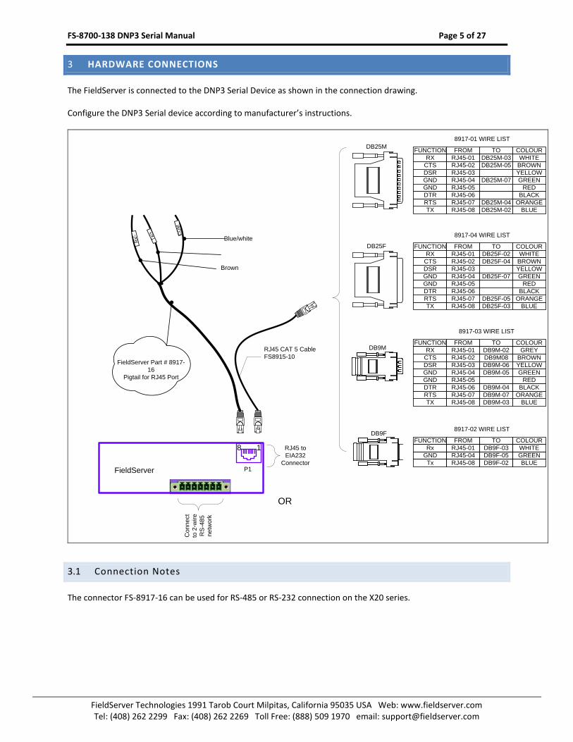
HARDWARE CONNECTIONS 3
The FieldServer is connected to the DNP3 Serial Device as shown in the connection drawing.
Configure the DNP3 Serial device according to manufacturer’s instructions.
FieldServer P1
18
RJ45 CAT 5 Cable
FS8915-10
Rx/-
Tx/
+
FieldServer Part # 8917-
16
Pigtail for RJ45 Port
Brown
Blue/white
OR
CO
M
Co
nn
ect
to 2
-wire
RS
-48
5
ne
two
rk
DB25M
FUNCTION FROM TO COLOUR
Rx RJ45-01 DB9F-03 WHITE
GND RJ45-04 DB9F-05 GREEN
Tx RJ45-08 DB9F-02 BLUE
FUNCTION FROM TO COLOUR
RX RJ45-01 DB25M-03 WHITE
CTS RJ45-02 DB25M-05 BROWN
DSR RJ45-03 YELLOW
GND RJ45-04 DB25M-07 GREEN
GND RJ45-05 RED
TX RJ45-08 DB25M-02 BLUE
RTS RJ45-07 DB25M-04 ORANGE
DTR RJ45-06 BLACK
8917-01 WIRE LIST
FUNCTION FROM TO COLOUR
RX RJ45-01 DB25F-02 WHITE
CTS RJ45-02 DB25F-04 BROWN
DSR RJ45-03 YELLOW
GND RJ45-04 DB25F-07 GREEN
GND RJ45-05 RED
TX RJ45-08 DB25F-03 BLUE
RTS RJ45-07 DB25F-05 ORANGE
DTR RJ45-06 BLACK
8917-04 WIRE LIST
DB25F
DB9MFUNCTION FROM TO COLOUR
RX RJ45-01 DB9M-02 GREY
CTS RJ45-02 DB9M08 BROWN
DSR RJ45-03 DB9M-06 YELLOW
GND RJ45-04 DB9M-05 GREEN
GND RJ45-05 RED
TX RJ45-08 DB9M-03 BLUE
RTS RJ45-07 DB9M-07 ORANGE
DTR RJ45-06 DB9M-04 BLACK
8917-03 WIRE LIST
DB9F8917-02 WIRE LIST
RJ45 to
EIA232
Connector
3.1 Connection Notes
The connector FS-8917-16 can be used for RS-485 or RS-232 connection on the X20 series.

FS-8700-138 DNP3 Serial Manual Page 6 of 27
FieldServer Technologies 1991 Tarob Court Milpitas, California 95035 USA Web: www.fieldserver.com Tel: (408) 262 2299 Fax: (408) 262 2269 Toll Free: (888) 509 1970 email: [email protected]
DATA ARRAY PARAMETERS 4
Data Arrays are “protocol neutral” data buffers for storage of data to be passed between protocols. It is necessary to declare the data format of each of the Data Arrays to facilitate correct storage of the relevant data.
Section Title
Data_Arrays
Column Title Function Legal Values
Data_Array_Name Provide name for Data Array Up to 15 alphanumeric characters
Data_Array_Format Provide data format. Each Data Array can only take on one format.
Float, Bit, UInt16, SInt16, Byte, UInt32, SInt32
Data_Array_Length Number of Data Objects. Must be larger than the data storage area required by the Map Descriptors for the data being placed in this array.
1-10, 000
Example
// Data Arrays Data_Arrays Data_Array_Name , Data_Array_Format , Data_Array_Length DA_BO , Bit , 50 DA_BI , Bit , 50 DA_AI , SInt32 , 50 DA_AOS , SInt16 , 50 DA_CNT , UInt32 , 50 DA_BO_Status , Byte , 50 DA_BI_Status , Byte , 50 DA_AI_Status , Byte , 50 DA_AO_Status , Byte , 50 DA_CNT_Status , Byte , 50 DA_CNTF_Status , Byte , 50 DA_Crob_Parms , UINt32 , 200 DA_Softver , Byte , 8 DA_Hardver , Byte , 80 DA_Userid , Byte , 80 DA_Serial , Byte , 80 DA_Prodname , Byte , 80 DA_Manufname , Byte , 80 DA_Allattrib , Byte , 80 DA_Listattrib , Byte , 80 DA_BI_E_TIME , Byte , 300

FS-8700-138 DNP3 Serial Manual Page 7 of 27
FieldServer Technologies 1991 Tarob Court Milpitas, California 95035 USA Web: www.fieldserver.com Tel: (408) 262 2299 Fax: (408) 262 2269 Toll Free: (888) 509 1970 email: [email protected]
CONFIGURING THE FIELDSERVER AS A DNP3 SERIAL CLIENT 5
For a detailed discussion on FieldServer configuration, please refer to the FieldServer Configuration Manual. The information that follows describes how to expand upon the factory defaults provided in the configuration files included with the FieldServer (See “.csv” sample files provided with the FieldServer).
This section documents and describes the parameters necessary for configuring the FieldServer as Client (Master) to communicate with a DNP3 Serial Server (Remote Outstation).
The configuration file tells the FieldServer about its interfaces, and the routing of data required. In order to enable the FieldServer for DNP3 Serial communications, the driver independent FieldServer buffers need to be declared in the “Data Arrays” section, the destination device addresses need to be declared in the “Client Side Nodes” section, and the data required from the servers needs to be mapped in the “Client Side Map Descriptors” section. Details on how to do this can be found below.
Note that in the tables, * indicates an optional parameter, with the bold legal value being the default.
5.1 Client Side Connection Parameters
Section Title
Connections
Column Title Function Legal Values
Port Specify which port the device is connected to the FieldServer
P1-P8, R1-R21
Protocol Specify protocol used Dnp3Ser, DNP3_Ser
Baud* Specify baud rate 300, 600, 1200, 2400, 4800, 9600, 19200, 38400, 76800, 115200
Parity* Specify parity None , Even, Odd
Data_Bits* Specify data bits 8 , 7
Stop_Bits* Specify stop bits 1 , 2
Poll_Delay* Time between internal polls 0- 65.535s , 0.050s
DNP3_Master_Address* Specify Master data link address 0 – 65519,
DNP3_Broadcast_Address*
Specify the Broadcast destination address. The driver uses this as the destination address when sending the following commands
a) Direct operate no ack (0x06) b) Freeze and no ack (0x08) c) Freeze, clear and no ack (0x0A)
65533, 65534, 65535
DNP3_UTC_Correction* Specify the correction required to set the time to UTC time. Ensure that the local time is set on the FieldServer (using Ruinet)
0, -2147483648 to 2147483647 (ms)
DNP3_Generate_Profile* Specify if it is required to generate dnp3 xml profile file from FieldServer configuration file.
NO, YES
Example
// Client Side Connections Connections Port , Protocol , Baud , Parity , DNP3_Master_Address , Poll_Delay P1 , Dnp3Ser , 9600 , None , 100 , 0
1 Not all ports shown are necessarily supported by the hardware. Consult the appropriate Instruction manual for details of the ports available on specific hardware.
FS-8700-138 DNP3 Serial Manual Page 8 of 27
FieldServer Technologies 1991 Tarob Court Milpitas, California 95035 USA Web: www.fieldserver.com Tel: (408) 262 2299 Fax: (408) 262 2269 Toll Free: (888) 509 1970 email: [email protected]
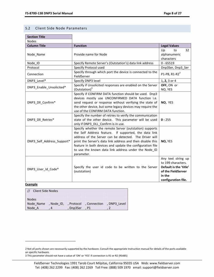
5.2 Client Side Node Parameters
Section Title
Nodes
Column Title Function Legal Values
Node_Name Provide name for Node Up to 32 alphanumeric characters
Node_ID Specify Remote Server’s (Outstation’s) data link address 0 - 65519
Protocol Specify Protocol used Dnp3Ser, Dnp3_Ser
Connection Specify through which port the device is connected to the FieldServer
P1-P8, R1-R22
DNP3_Level* Specify DNP3 level 1, 2, 3 or 4
DNP3_Enable_Unsolicited* Specify if Unsolicited responses are enabled on the Server (Outstation)
3
OFF, ON or NO, YES
DNP3_Dll_Confirm*
Specify if CONFIRM DATA function should be used. Dnp3 devices mostly use UNCONFIRMED DATA function i.e. send request or response without verifying the state of the other device, but some legacy devices may require the use of the CONFIRM DATA function.
NO, YES
DNP3_Dll_Retries* Specify the number of retries to verify the communication state of the other device. This parameter will be used only if DNP3_DLL_Confirm is in use.
0 - 255
DNP3_Self_Address_Support*
Specify whether the remote Server (outstation) supports the Self Address feature. If supported, the data link address of the Server can be detected. The Driver will print the Server’s data link address and then disable this feature in both devices and update the configuration file to use the known data link address under the Node_ID parameter.
NO, YES
DNP3_User_Id_Code* Specify the user id code to be written to the Server (outstation)
Any text string up to 199 characters. Default is the ‘title’ of the FieldServer in the configuration file.
Example
// Client Side Nodes Nodes Node_Name , Node_ID, , Protocol , Connection , DNP3_Level Node_A , 4 , Dnp3Ser , P1 , 2
2 Not all ports shown are necessarily supported by the hardware. Consult the appropriate Instruction manual for details of the ports available on specific hardware. 3 This parameter should not have a value of ‘ON’ or ‘YES’ if connection is R1 or R2 (RS485)

FS-8700-138 DNP3 Serial Manual Page 9 of 27
FieldServer Technologies 1991 Tarob Court Milpitas, California 95035 USA Web: www.fieldserver.com Tel: (408) 262 2299 Fax: (408) 262 2269 Toll Free: (888) 509 1970 email: [email protected]
5.3 Client Side Map Descriptor Parameters
5.3.1 FieldServer Related Map Descriptor Parameters
Column Title Function Legal Values
Map_Descriptor_Name Name of this Map Descriptor Up to 32 alphanumeric characters
Data_Array_Name Name of Data Array where data is to be stored in the FieldServer
One of the Data Array names from Section 4.
Data_Array_Offset Starting location in Data Array 0 to (Data_Array_Length-1) as specified in Section 4.
Function Function of Client Map Descriptor Rdbc, Wrbc, Wrbx, Passive
5.3.2 Driver Related Map Descriptor Parameters
Column Title Function Legal Values
Node_Name Name of Node to fetch data from One of the Node names specified in Section 5.2
Length Length of Map Descriptor. (The number of object instances)
1,2,3 etc
Address Specify object’s index number 0, 1, 2, etc
DNP3Group* Specify DNP3 Group number. This is a numeric representation of the Object Data Type. Refer to Appendix B.1
0, Refer to Appendix B.1
DNP3Variation* Specify format or additional information relevant to DNP3Group.
0, Refer to Appendix B.1
DNP3Function*
Specify function as read, write, operate etc 1 read 2 write 3, 4 select & operate 5 direct operate 6 direct operate and no ack 7 Freeze 8 Freeze no ack 9 Freeze clear 10 Freeze, clear and no ack 13 cold restart
Refer to Appendix B.1 for default values and all options.
DNP3Qualifier*
Specify the way driver encodes object index and length in DNP3 request. For example 0 start-stop ; driver will encode the range (address to address+length-1 ) as start and stop address and it will use 1 byte to encode start and 1 byte to encode stop 0 (start-stop 1 byte each) 1 (start-stop 2 bytes each) 6 (no range or all) 7 (limited quantity, 1 byte indicates length) 8 (limited quantity, 2 bytes indicate length) 23 (each index encoded - use 1 byte ) 40 ( each index encoded - use 2 bytes )
Refer to Appendix B.1 for default values and all options.
FS-8700-138 DNP3 Serial Manual Page 10 of 27
FieldServer Technologies 1991 Tarob Court Milpitas, California 95035 USA Web: www.fieldserver.com Tel: (408) 262 2299 Fax: (408) 262 2269 Toll Free: (888) 509 1970 email: [email protected]
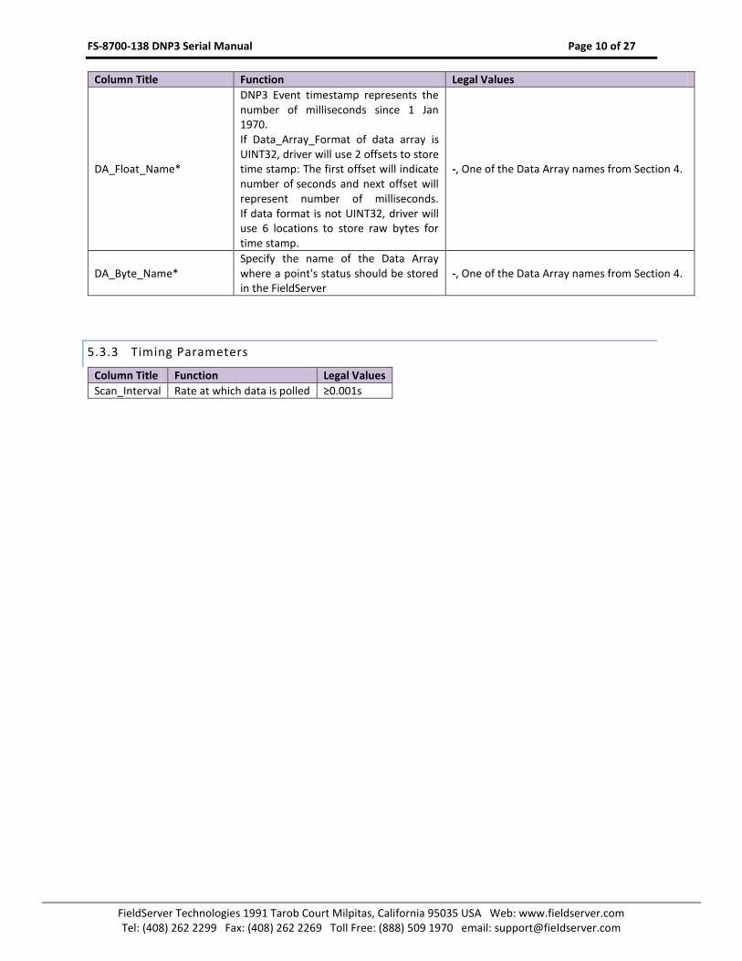
Column Title Function Legal Values
DA_Float_Name*
DNP3 Event timestamp represents the number of milliseconds since 1 Jan 1970. If Data_Array_Format of data array is UINT32, driver will use 2 offsets to store time stamp: The first offset will indicate number of seconds and next offset will represent number of milliseconds. If data format is not UINT32, driver will use 6 locations to store raw bytes for time stamp.
-, One of the Data Array names from Section 4.
DA_Byte_Name* Specify the name of the Data Array where a point's status should be stored in the FieldServer
-, One of the Data Array names from Section 4.
5.3.3 Timing Parameters
Column Title Function Legal Values
Scan_Interval Rate at which data is polled ≥0.001s

FS-8700-138 DNP3 Serial Manual Page 11 of 27
FieldServer Technologies 1991 Tarob Court Milpitas, California 95035 USA Web: www.fieldserver.com Tel: (408) 262 2299 Fax: (408) 262 2269 Toll Free: (888) 509 1970 email: [email protected]
5.4 Map Descriptor Example. READ
5.4.1 Binary Output (DNP3Group 10)
Map_Descriptors
Map_Descriptor_Name , Scan_Interval , Data_Array_Name , Data_Array_Offset , Function , Node_Name , DNP3Group , Address , Length , DA_BYTE_NAME
ReadBO1 , 5s , DA_BO , 0 , Rdbc , Node_A , 10 , 0 , 25 , DA_BO_Status
5.4.2 Binary Input (DNP3Group 1)
Events read by the Master or sent by the Server in unsolicited responses will also be stored by this Map Descriptor.
Map_Descriptors
Map_Descriptor_Name , Scan_Interval , Data_Array_Name , Data_Array_Offset , Function , Node_Name , DNP3Group , Address , Length , DA_Float_Name , DA_BYTE_NAME
ReadBI1 , 5s , DA_BI , 0 , Rdbc , Node_A , 1 , 0 , 25 , DA_BI_E_Time , DA_BI_Status
5.4.3 Analog Input (DNP3Group 30)
Events read by the Master or sent by the Server in unsolicited responses will also be stored by this Map Descriptor.
Map_Descriptors
Map_Descriptor_Name , Scan_Interval , Data_Array_Name , Data_Array_Offset , Function , Node_Name , DNP3Group , Address , Length , DA_BYTE_NAME
ReadAI1 , 5s , DA_AI , 0 , Rdbc , Node_A , 30 , 0 , 25 , DA_AI_Status
Only Index 0-24 will be stored. If more Binary outputs exist at the Server, increase length or add additional Passive Map Descriptors.
Binary output value will be stored here.
Status flags will be stored here.
All Binary outputs will be read every 5s
Only Index 0-24 will be stored. If more Binary Inputs exist at the Server, increase length or add additional Passive Map Descriptors.
Binary input value will be stored here. Status flags will
be stored here.
All Binary inputs will be read every 5s
Event Time will be stored here if provided by Server.
Only Index 0-24 will be stored. If more Analog Inputs exist at the Server, increase length or add additional Passive Map Descriptors.
Analog Input value will be stored here.
Status flags will be stored here.
All Analog Inputs will be read every 5s
FS-8700-138 DNP3 Serial Manual Page 12 of 27
FieldServer Technologies 1991 Tarob Court Milpitas, California 95035 USA Web: www.fieldserver.com Tel: (408) 262 2299 Fax: (408) 262 2269 Toll Free: (888) 509 1970 email: [email protected]
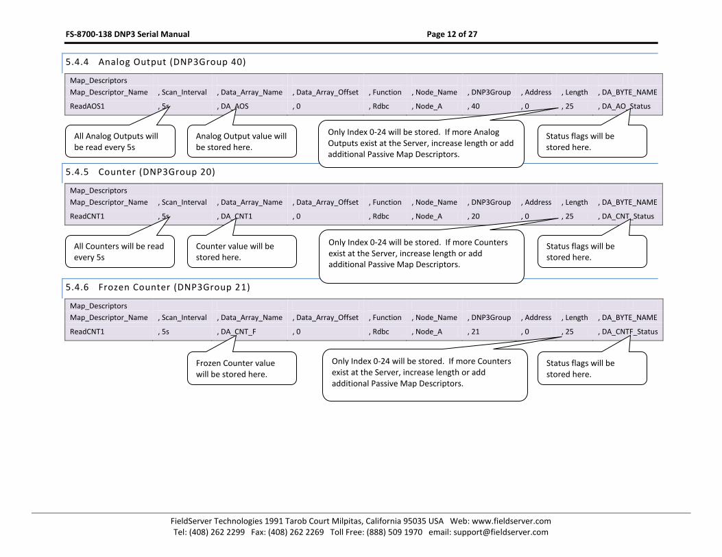
5.4.4 Analog Output (DNP3Group 40)
Map_Descriptors
Map_Descriptor_Name , Scan_Interval , Data_Array_Name , Data_Array_Offset , Function , Node_Name , DNP3Group , Address , Length , DA_BYTE_NAME
ReadAOS1 , 5s , DA_AOS , 0 , Rdbc , Node_A , 40 , 0 , 25 , DA_AO_Status
5.4.5 Counter (DNP3Group 20)
Map_Descriptors
Map_Descriptor_Name , Scan_Interval , Data_Array_Name , Data_Array_Offset , Function , Node_Name , DNP3Group , Address , Length , DA_BYTE_NAME
ReadCNT1 , 5s , DA_CNT1 , 0 , Rdbc , Node_A , 20 , 0 , 25 , DA_CNT_Status
5.4.6 Frozen Counter (DNP3Group 21)
Map_Descriptors
Map_Descriptor_Name , Scan_Interval , Data_Array_Name , Data_Array_Offset , Function , Node_Name , DNP3Group , Address , Length , DA_BYTE_NAME
ReadCNT1 , 5s , DA_CNT_F , 0 , Rdbc , Node_A , 21 , 0 , 25 , DA_CNTF_Status
Only Index 0-24 will be stored. If more Analog Outputs exist at the Server, increase length or add additional Passive Map Descriptors.
Analog Output value will be stored here.
Status flags will be stored here.
All Analog Outputs will be read every 5s
Only Index 0-24 will be stored. If more Counters exist at the Server, increase length or add additional Passive Map Descriptors.
Counter value will be stored here.
Status flags will be stored here.
All Counters will be read every 5s
Status flags will be stored here.
Frozen Counter value will be stored here.
Only Index 0-24 will be stored. If more Counters exist at the Server, increase length or add additional Passive Map Descriptors.
FS-8700-138 DNP3 Serial Manual Page 13 of 27
FieldServer Technologies 1991 Tarob Court Milpitas, California 95035 USA Web: www.fieldserver.com Tel: (408) 262 2299 Fax: (408) 262 2269 Toll Free: (888) 509 1970 email: [email protected]
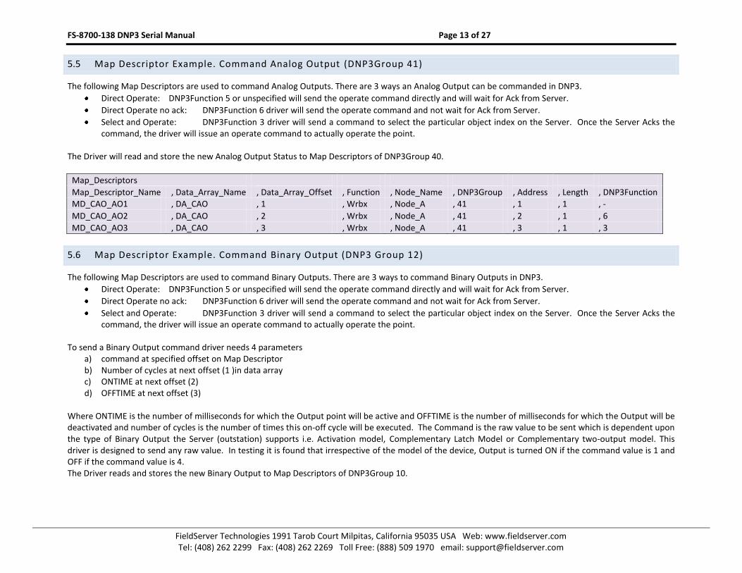
5.5 Map Descriptor Example. Command Analog Output (DNP3Group 41)
The following Map Descriptors are used to command Analog Outputs. There are 3 ways an Analog Output can be commanded in DNP3.
Direct Operate: DNP3Function 5 or unspecified will send the operate command directly and will wait for Ack from Server.
Direct Operate no ack: DNP3Function 6 driver will send the operate command and not wait for Ack from Server.
Select and Operate: DNP3Function 3 driver will send a command to select the particular object index on the Server. Once the Server Acks the command, the driver will issue an operate command to actually operate the point.
The Driver will read and store the new Analog Output Status to Map Descriptors of DNP3Group 40.
Map_Descriptors
Map_Descriptor_Name , Data_Array_Name , Data_Array_Offset , Function , Node_Name , DNP3Group , Address , Length , DNP3Function
MD_CAO_AO1 , DA_CAO , 1 , Wrbx , Node_A , 41 , 1 , 1 , -
MD_CAO_AO2 , DA_CAO , 2 , Wrbx , Node_A , 41 , 2 , 1 , 6
MD_CAO_AO3 , DA_CAO , 3 , Wrbx , Node_A , 41 , 3 , 1 , 3
5.6 Map Descriptor Example. Command Binary Output (DNP3 Group 12)
The following Map Descriptors are used to command Binary Outputs. There are 3 ways to command Binary Outputs in DNP3.
Direct Operate: DNP3Function 5 or unspecified will send the operate command directly and will wait for Ack from Server.
Direct Operate no ack: DNP3Function 6 driver will send the operate command and not wait for Ack from Server.
Select and Operate: DNP3Function 3 driver will send a command to select the particular object index on the Server. Once the Server Acks the command, the driver will issue an operate command to actually operate the point.
To send a Binary Output command driver needs 4 parameters
a) command at specified offset on Map Descriptor b) Number of cycles at next offset (1 )in data array c) ONTIME at next offset (2) d) OFFTIME at next offset (3)
Where ONTIME is the number of milliseconds for which the Output point will be active and OFFTIME is the number of milliseconds for which the Output will be deactivated and number of cycles is the number of times this on-off cycle will be executed. The Command is the raw value to be sent which is dependent upon the type of Binary Output the Server (outstation) supports i.e. Activation model, Complementary Latch Model or Complementary two-output model. This driver is designed to send any raw value. In testing it is found that irrespective of the model of the device, Output is turned ON if the command value is 1 and OFF if the command value is 4. The Driver reads and stores the new Binary Output to Map Descriptors of DNP3Group 10.

FS-8700-138 DNP3 Serial Manual Page 14 of 27
FieldServer Technologies 1991 Tarob Court Milpitas, California 95035 USA Web: www.fieldserver.com Tel: (408) 262 2299 Fax: (408) 262 2269 Toll Free: (888) 509 1970 email: [email protected]
Map_Descriptors
Map_Descriptor_Name , Data_Array_Name , Data_Array_Offset , Function , Node_Name , DNP3Group , Address , Length , DNP3Function
MD_CROB1 , DA_CROB0 , 0 , Wrbx , Node_A , 12 , 1 , 1 , -
MD_CROB2 , DA_CROB1 , 0 , Wrbx , Node_A , 12 , 2 , 1 , 6
MD_CROB3 , DA_CROB2 , 0 , Wrbx , Node_A , 12 , 3 , 1 , 3
5.7 Map Descriptor Example. Freeze Counters
The following Map Descriptor will issue the command to freeze counter objects. Whenever the value at the specified offset is updated, the driver will trigger this Map Descriptor. Refer to the description of the DNP3Function for counters in Section 0.
Map_Descriptors
Map_Descriptor_Name , Data_Array_Name , Data_Array_Offset , Function , Node_Name , DNP3Group , Length , DNP3Function
FreezeCNT1 , DA_CNT_FR , 0 , Wrbc , Node_A , 20 , 1 , 7
DNP3Function Actions
7 Freeze Server will copy the counter values to the frozen counters
8 Freeze no ack As 7 but Server will not send a response to the Client
9 Freeze clear Server will copy the counter values to the frozen counters and clear the counters
10 Freeze, clear and no ack As 10 but Server will not send a response to the Client
The following Map Descriptor will issue the command to freeze counter objects every 50s.
Descriptors
Map_Descriptor_Name , Data_Array_Name , Data_Array_Offset , Function , Node_Name , DNP3Group , Length , DNP3Function , Scan_Interval
FreezeCNT1 , DA_CNT_FR , 0 , Wrbc , Node_A , 20 , 1 , 7 , 50s

FS-8700-138 DNP3 Serial Manual Page 15 of 27
FieldServer Technologies 1991 Tarob Court Milpitas, California 95035 USA Web: www.fieldserver.com Tel: (408) 262 2299 Fax: (408) 262 2269 Toll Free: (888) 509 1970 email: [email protected]
CONFIGURING THE FIELDSERVER AS A DNP3 SERIAL SERVER 6
For a detailed discussion on FieldServer configuration, please refer to the FieldServer Configuration Manual. The information that follows describes how to expand upon the factory defaults provided in the configuration files included with the FieldServer (See “.csv” sample files provided with the FieldServer).
This section documents and describes the parameters necessary for configuring the FieldServer to communicate with a DNP3 Serial Client (Master).
The configuration file tells the FieldServer about its interfaces, and the routing of data required. In order to enable the FieldServer for DNP3 Serial communications, the driver independent FieldServer buffers need to be declared in the “Data Arrays” section, the FieldServer virtual node(s) needs to be declared in the “Server Side Nodes” section, and the data to be provided to the client needs to be mapped in the “Server Side Map Descriptors” section. Details on how to do this can be found below.
Note that in the tables, * indicates an optional parameter, with the bold legal value being the default.
6.1 Server Side Connection Parameters
Section Title
Connections
Column Title Function Legal Values
Baud* Specify baud rate
300, 600, 1200, 2400, 4800, 9600, 19200, 38400, 76800, 115200
Parity* Specify parity None , Even, Odd
Data_Bits* Specify data bits 8 , 7
Stop_Bits* Specify stop bits 1 , 2
Server_Hold_Timeout* Specifies time FieldServer will reserve the Server side connection while waiting for the Client side to update data in the Data_Array
>1.0s, 5s
DNP3_Master_Address*
Specify Remote Master’s data link address. If unspecified, the driver will default to 0, but will dynamically update it as soon it gets any message from the Master. If specified, and it gets a different Master address in a message, the driver will print the message with Master’s data link address, and then update the configuration file.
0 – 65519.
Protocol Specify protocol used Dnp3Ser, DNP3_Ser
DNP3_Generate_Profile* Specify if it is required to generate dnp3 xml profile file from FieldServer configuration file.
NO, YES
Example
// Server Side Connections Connections Port , Protocol , Baud , Parity DNP3_Master_Address P1 , Dnp3Ser , 9600 , None , -

FS-8700-138 DNP3 Serial Manual Page 16 of 27
FieldServer Technologies 1991 Tarob Court Milpitas, California 95035 USA Web: www.fieldserver.com Tel: (408) 262 2299 Fax: (408) 262 2269 Toll Free: (888) 509 1970 email: [email protected]
6.2 Server Side Node Parameters
Section Title
Nodes
Column Title Function Legal Values
Node_Name Provide name for Node Up to 32 alphanumeric characters
Node_ID Specify this Server’s (Outstation’s) data link address 0 - 65519
Protocol Specify Protocol used Dnp3Ser, Dnp3_Ser
Timeout* Specify timeout in seconds. This timeout is used for various timeouts. For example confirmation timeout, ‘select’ timeout etc
0-65.534, 2
DNP3_Level* Specify DNP3 level 1, 2, 3 or 4
DNP3_Enable_Unsolicited* Specify if Unsolicited responses are enabled or not.4
OFF, ON or NO, YES
DNP3_Unsol_Retries* Specify the number of times the driver should re-transmit unsolicited responses if it does not get confirmation from Master. 4294967295 is considered infinite.
0 - 4294967295
DNP3_Dll_Confirm*
Specify if CONFIRM DATA function should be used or not. Dnp3 devices mostly use UNCONFIRMED DATA function i.e. send request or response without verifying the state of the other device, but some legacy devices may require the use of the CONFIRM DATA function.
NO, YES
DNP3_Dll_Retries* Specify the number of retries to verify the communication state of the other device. This parameter will be used only if DNP3_DLL_Confirm is in use.
0 - 255
DNP3_User_Id_Code* Specify the custom user id code text
Any text string up to 199 characters. Default is the ‘title’ of the FieldServer in the configuration file.
DNP3_Max_Events*
Specify the event queue length. This is the maximum, number of unconfirmed events that driver can keep in queue. If the master remains unable to confirm the events, the new events will be discarded. The driver will keep the Bit set in every response from the Master to indicate event queue overflow.
0 – 65535, 50
DNP3_Self_Address_Support*
Enable/disable Self Address support feature. This feature is normally used to discover the data link address of the Server (outstation) if it is unknown during installation and the Outstation supports this feature. This is redundant in explicitly configurable FieldServers because the correct data link address (Node_ID) is required in the configuration file to enable/disable this feature.
NO, YES
DNP3_Time_Sync_Expire* Specify the time in minutes after which the driver will set the ‘Need Time’ bit to indicate to the Master to set the
2-28800 , 60 (minutes)
4 This parameter should not have a value of ‘ON’ or ‘YES’ if connection is R1 or R2 (RS485)
FS-8700-138 DNP3 Serial Manual Page 17 of 27
FieldServer Technologies 1991 Tarob Court Milpitas, California 95035 USA Web: www.fieldserver.com Tel: (408) 262 2299 Fax: (408) 262 2269 Toll Free: (888) 509 1970 email: [email protected]
Section Title
Nodes
Column Title Function Legal Values
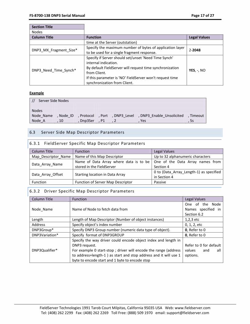
time at the Server (outstation)
DNP3_MX_Fragment_Size* Specify the maximum number of bytes of application layer to be used for a single fragment response.
2-2048
DNP3_Need_Time_Synch*
Specify if Server should set/unset 'Need Time Synch' internal indication. By default FieldServer will request time synchronization from Client. If this parameter is 'NO' FieldServer won't request time synchronization from Client.
YES, -, NO
Example
// Server Side Nodes Nodes Node_Name , Node_ID , Protocol , Port , DNP3_Level , DNP3_Enable_Unsolicited , Timeout Node_A , 10 , Dnp3Ser , P1 , 2 , Yes , 5s
6.3 Server Side Map Descriptor Parameters
6.3.1 FieldServer Specific Map Descriptor Parameters
Column Title Function Legal Values
Map_Descriptor_Name Name of this Map Descriptor Up to 32 alphanumeric characters
Data_Array_Name Name of Data Array where data is to be stored in the FieldServer
One of the Data Array names from Section 4
Data_Array_Offset Starting location in Data Array 0 to (Data_Array_Length-1) as specified in Section 4
Function Function of Server Map Descriptor Passive
6.3.2 Driver Specific Map Descriptor Parameters
Column Title Function Legal Values
Node_Name Name of Node to fetch data from One of the Node Names specified in Section 6.2
Length Length of Map Descriptor (Number of object instances) 1,2,3 etc
Address Specify object’s index number 0, 1, 2, etc
DNP3Group* Specify DNP3 Group number (numeric data type of object). 0, Refer to 0
DNP3Variation* Specify format of DNP3GROUP 0, Refer to 0
DNP3Qualifier*
Specify the way driver could encode object index and length in DNP3 request. For example 0 start-stop ; driver will encode the range (address to address+length-1 ) as start and stop address and it will use 1 byte to encode start and 1 byte to encode stop
Refer to 0 for default values and all options.

FS-8700-138 DNP3 Serial Manual Page 18 of 27
FieldServer Technologies 1991 Tarob Court Milpitas, California 95035 USA Web: www.fieldserver.com Tel: (408) 262 2299 Fax: (408) 262 2269 Toll Free: (888) 509 1970 email: [email protected]
Column Title Function Legal Values
DNP3DataClass*
Specify the data class of the object. 0 – Static data (current value), no events will be generated for this data 1, 2, 3 – Event classes, events will be generated for this data. 255 – Class None. When class0 data is requested, driver will provide static data from class0, class1, class2 and class3. There isn’t any special consideration or priority for various event classes like Class1, class2 or class3, but normally applications assign Binary Input as class1, Analog Input as class2 and Counter as class3 data.
0, 1, 2, 3, 255
DNP3EventVariation* Similar to DNP3Variation, but applicable only for Event objects. Default event variation will be used when sending events in unsolicited response or when the parameter is not specified.
Refer to 0 for default values and all options.
DNP3EventQualifier* Similar to DNP3Qualifier, but applicable only for Event objects.
Event_Deadband* Specify the deadband. If value changes in this band, event will not be generated. This is applicable to Analog Input and Counter objects
0, -2147483648 to 2147483647
DA_Float_Name* Specify the name of the Data Array to configure the FieldServer to accept commands on Binary Output objects
-, One of the Data Array names from Section 4.
DNP3TimeDA*
Used to store the event time reported from the remote device. If this parameter is not defined, the FieldServer calculates the event time as per its own clock. To override the default event time, specify the name of a Data Array to hold the event time.
One of the Data Array names from Section 4.
DNP3StatusDA*
Used to store status flags for the objects from the remote device. If this parameter is not defined, the FieldServer uses the status of the data array objects. To override the default status, specify the name of a Data Array which holds the objects status.
One of the Data Array names from Section 4
FS-8700-138 DNP3 Serial Manual Page 19 of 27
FieldServer Technologies 1991 Tarob Court Milpitas, California 95035 USA Web: www.fieldserver.com Tel: (408) 262 2299 Fax: (408) 262 2269 Toll Free: (888) 509 1970 email: [email protected]
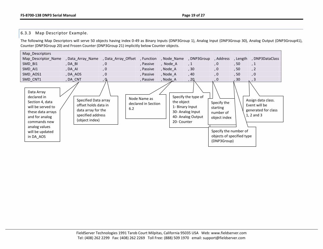
6.3.3 Map Descriptor Example.
The following Map Descriptors will serve 50 objects having index 0-49 as Binary Inputs (DNP3Group 1), Analog Input (DNP3Group 30), Analog Output (DNP3Group41), Counter (DNP3Group 20) and Frozen Counter (DNP3Group 21) implicitly below Counter objects.
Map_Descriptors
Map_Descriptor_Name , Data_Array_Name , Data_Array_Offset , Function , Node_Name , DNP3Group , Address , Length , DNP3DataClass
SMD_BI1 , DA_BI , 0 , Passive , Node_A , 1 , 0 , 50 , 1
SMD_AI1 , DA_AI , 0 , Passive , Node_A , 30 , 0 , 50 , 2
SMD_AOS1 , DA_AOS , 0 , Passive , Node_A , 40 , 0 , 50 , 0
SMD_CNT1 , DA_CNT , 0 , Passive , Node_A , 20 , 0 , 30 , 3
Data Array declared in Section 4, data will be served to these data arrays and for analog commands new analog values will be updated in DA_AOS
Specify the type of the object 1- Binary Input 30- Analog Input 40- Analog Output 20- Counter
Node Name as declared in Section 6.2
Assign data class. Event will be generated for class 1, 2 and 3
Specify the starting number of object index
Specified Data array offset holds data in data array for the specified address (object index)
Specify the number of objects of specified type (DNP3Group)
FS-8700-138 DNP3 Serial Manual Page 20 of 27
FieldServer Technologies 1991 Tarob Court Milpitas, California 95035 USA Web: www.fieldserver.com Tel: (408) 262 2299 Fax: (408) 262 2269 Toll Free: (888) 509 1970 email: [email protected]
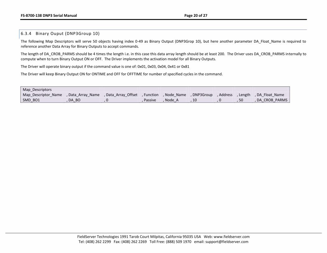
6.3.4 Binary Ouput (DNP3Group 10)
The following Map Descriptors will serve 50 objects having index 0-49 as Binary Output (DNP3Grop 10), but here another parameter DA_Float_Name is required to reference another Data Array for Binary Outputs to accept commands.
The length of DA_CROB_PARMS should be 4 times the length i.e. in this case this data array length should be at least 200. The Driver uses DA_CROB_PARMS internally to compute when to turn Binary Output ON or OFF. The Driver implements the activation model for all Binary Outputs.
The Driver will operate binary output if the command value is one of: 0x01, 0x03, 0x04, 0x41 or 0x81
The Driver will keep Binary Output ON for ONTIME and OFF for OFFTIME for number of specified cycles in the command.
Map_Descriptors
Map_Descriptor_Name , Data_Array_Name , Data_Array_Offset , Function , Node_Name , DNP3Group , Address , Length , DA_Float_Name
SMD_BO1 , DA_BO , 0 , Passive , Node_A , 10 , 0 , 50 , DA_CROB_PARMS

FS-8700-138 DNP3 Serial Manual Page 21 of 27
FieldServer Technologies 1991 Tarob Court Milpitas, California 95035 USA Web: www.fieldserver.com Tel: (408) 262 2299 Fax: (408) 262 2269 Toll Free: (888) 509 1970 email: [email protected]
Appendix A. USEFUL FEATURES
Appendix A.1. Map Descriptor Example. Device Attribute Read
The following set of Map Descriptors are required to read/write Server device attributes.
Map Descriptor AllAttriRqst attribute 254 sends a request to read all device attributes, but nothing is stored in associated Data Array DA_ALLATTRIB because the data is parsed and will be stored on other Map Descriptors depending upon the data type (DNP3Variation). For example software version (variation 242) will be stored in DA_SOFTVER; User ID Code (variation 246) will be stored in DA_USERID and so on.
List Map Descriptor ListAttrVar attribute 255 sends a request to read available attributes at the Server and their read/write nature, but not the actual values of attributes. The Attribute variation number and its read/write flag will be stored as a pair in DA_LISTATTRIB. E.g. offset 0 holds variation number and offset 1 its read/write flag, offset 2 will hold next variation number and offset 3 its read/write flag and so on.
Attribute variation 246 is optionally writable. Use the function Wrbx and update DA_USERID to write new user id code attribute 246 to Server.
To read each attribute individually, change the functions from Passive to Rdbc.
Map_Descriptors
Map_Descriptor_Name , Scan_Interval , Data_Array_Name , Data_Array_Offset , Function , Node_Name , DNP3Group , DNP3Variation , Length , DNP3Function
ManfSoftVer , 100s , DA_SOFTVER , 0 , Passive , Node_A , 0 , 242 , 8 , -
ManfHardVer , 100s , DA_HARDVER , 0 , Passive , Node_A , 0 , 243 , 80 , -
UserIDcodenum , 100s , DA_USERID , 0 , Wrbx , Node_A , 0 , 246 , 80 , 2
SerialNum , 100s , DA_SERIAL , 0 , Passive , Node_A , 0 , 248 , 80 , -
ProdNameModel , 100s , DA_PRODNAME , 0 , Passive , Node_A , 0 , 250 , 80 , -
ManfName , 100s , DA_MANUFNAME , 0 , Passive , Node_A , 0 , 252 , 80 , -
AllAttriRqst , 100s , DA_ALLATTRIB , 0 , Rdbc , Node_A , 0 , 254 , 80 , -
ListAttriVar , 100s , DA_LISTATTRIB , 0 , Rdbc , Node_A , 0 , 255 , 80 , -

FS-8700-138 DNP3 Serial Manual Page 22 of 27
FieldServer Technologies 1991 Tarob Court Milpitas, California 95035 USA Web: www.fieldserver.com Tel: (408) 262 2299 Fax: (408) 262 2269 Toll Free: (888) 509 1970 email: [email protected]
Appendix A.2. Map Descriptor Example. Event Read
Appendix A.2.1. Binary Input Event (DNP3Group 2)
The Map Descriptor Poller_BI_Events will read all Binary Input events every 3s. (Qualifier is not specified). The Map Descriptor Poller_BI_Events10 and 10b will read up to 10 Binary Input events every 3s. Qualifier 7 will cause the length to be encoded in 1 byte, while Qualifier 8 will cause the length to be encoded in 2 bytes. The response data from these requests will be stored on other Map Descriptors described with DNP3Group 1 (Binary Inputs)
Map_Descriptors
Map_Descriptor_Name , Scan_Interval , Data_Array_Name , Data_Array_Offset , Function , Node_Name , DNP3Group , Length , DNP3Qualifier
Poller_BI_Events , 3s , DA_BI_E_Poller , 0 , Rdbc , Node_A , 2 , 1 , -
Poller_BI_Events10 , 3s , DA_BI_E_Poller7 , 0 , Rdbc , Node_A , 2 , 10 , 7
Poller_BI_Events 10b , 3s , DA_BI_E_Poller8 , 0 , Rdbc , Node_A , 2 , 10 , 8
The following Map Descriptors will read all Binary Input events for the variation specified if the qualifier is not specified or is specified as 6 every 3s. If the qualifier is specified as 7 or 8 it will request only a limited number of events as per specified length. The response data from these requests will be stored on other Map Descriptors described with DNP3Group 1 (Binary Inputs)
Variation 1 – Without Time Variation 2 – With Absolute Time Variation 3 – With Relative Time
Map_Descriptors
Map_Descriptor_Name , Scan_Interval , Data_Array_Name , Data_Array_Offset , Function , Node_Name , DNP3Group , Length , DNP3Variation , DNP3Qualifier
Poller_BI_Events1 , 3s , DA_BI_E_Poller1 , 0 , Rdbc , Node_A , 2 , 1 , 1 , -
Poller_BI_Events2 , 3s , DA_BI_E_Poller2 , 0 , Rdbc , Node_A , 2 , 10 , 2 , 7
Poller_BI_Events3 , 3s , DA_BI_E_Poller3 , 0 , Rdbc , Node_A , 2 , 10 , 3 , 8
FS-8700-138 DNP3 Serial Manual Page 23 of 27
FieldServer Technologies 1991 Tarob Court Milpitas, California 95035 USA Web: www.fieldserver.com Tel: (408) 262 2299 Fax: (408) 262 2269 Toll Free: (888) 509 1970 email: [email protected]
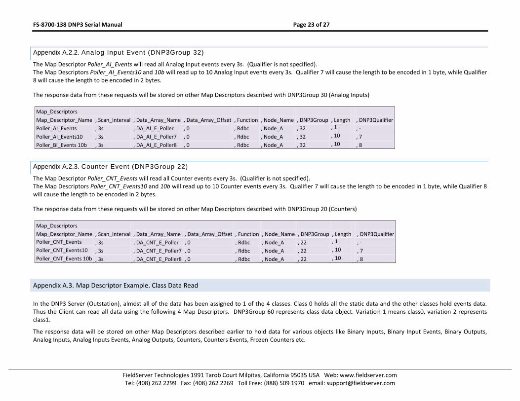
Appendix A.2.2. Analog Input Event (DNP3Group 32)
The Map Descriptor Poller_AI_Events will read all Analog Input events every 3s. (Qualifier is not specified). The Map Descriptors Poller_AI_Events10 and 10b will read up to 10 Analog Input events every 3s. Qualifier 7 will cause the length to be encoded in 1 byte, while Qualifier 8 will cause the length to be encoded in 2 bytes.
The response data from these requests will be stored on other Map Descriptors described with DNP3Group 30 (Analog Inputs)
Map_Descriptors
Map_Descriptor_Name , Scan_Interval , Data_Array_Name , Data_Array_Offset , Function , Node_Name , DNP3Group , Length , DNP3Qualifier
Poller_AI_Events , 3s , DA_AI_E_Poller , 0 , Rdbc , Node_A , 32 , 1 , -
Poller_AI_Events10 , 3s , DA_AI_E_Poller7 , 0 , Rdbc , Node_A , 32 , 10 , 7
Poller_BI_Events 10b , 3s , DA_AI_E_Poller8 , 0 , Rdbc , Node_A , 32 , 10 , 8
Appendix A.2.3. Counter Event (DNP3Group 22)
The Map Descriptor Poller_CNT_Events will read all Counter events every 3s. (Qualifier is not specified). The Map Descriptors Poller_CNT_Events10 and 10b will read up to 10 Counter events every 3s. Qualifier 7 will cause the length to be encoded in 1 byte, while Qualifier 8 will cause the length to be encoded in 2 bytes.
The response data from these requests will be stored on other Map Descriptors described with DNP3Group 20 (Counters)
Map_Descriptors
Map_Descriptor_Name , Scan_Interval , Data_Array_Name , Data_Array_Offset , Function , Node_Name , DNP3Group , Length , DNP3Qualifier
Poller_CNT_Events , 3s , DA_CNT_E_Poller , 0 , Rdbc , Node_A , 22 , 1 , -
Poller_CNT_Events10 , 3s , DA_CNT_E_Poller7 , 0 , Rdbc , Node_A , 22 , 10 , 7
Poller_CNT_Events 10b , 3s , DA_CNT_E_Poller8 , 0 , Rdbc , Node_A , 22 , 10 , 8
Appendix A.3. Map Descriptor Example. Class Data Read
In the DNP3 Server (Outstation), almost all of the data has been assigned to 1 of the 4 classes. Class 0 holds all the static data and the other classes hold events data. Thus the Client can read all data using the following 4 Map Descriptors. DNP3Group 60 represents class data object. Variation 1 means class0, variation 2 represents class1.
The response data will be stored on other Map Descriptors described earlier to hold data for various objects like Binary Inputs, Binary Input Events, Binary Outputs, Analog Inputs, Analog Inputs Events, Analog Outputs, Counters, Counters Events, Frozen Counters etc.
FS-8700-138 DNP3 Serial Manual Page 24 of 27
FieldServer Technologies 1991 Tarob Court Milpitas, California 95035 USA Web: www.fieldserver.com Tel: (408) 262 2299 Fax: (408) 262 2269 Toll Free: (888) 509 1970 email: [email protected]
Map_Descriptors
Map_Descriptor_Name , Scan_Interval , Data_Array_Name , Data_Array_Offset , Function , Node_Name , DNP3Group , DNP3Variation , Length
CMD_Class0_Poller , 16s , DA_Poller0 , 0 , Rdbc , Node_A , 60 , 1 , 1
CMD_Class1_Poller , 16s , DA_Poller1 , 0 , Rdbc , Node_A , 60 , 2 , 1
CMD_Class2_Poller , 16s , DA_Poller2 , 0 , Rdbc , Node_A , 60 , 3 , 1
CMD_Class3_Poller , 16s , DA_Poller3 , 0 , Rdbc , Node_A , 60 , 4 , 1
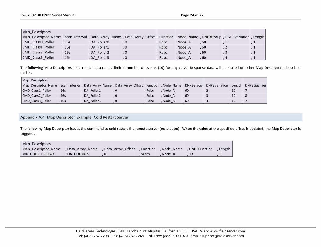
The following Map Descriptors send requests to read a limited number of events (10) for any class. Response data will be stored on other Map Descriptors described earlier.
Map_Descriptors
Map_Descriptor_Name , Scan_Interval , Data_Array_Name , Data_Array_Offset , Function , Node_Name , DNP3Group , DNP3Variation , Length , DNP3Qualifier
CMD_Class1_Poller , 16s , DA_Poller1 , 0 , Rdbc , Node_A , 60 , 2 , 10 , 7
CMD_Class2_Poller , 16s , DA_Poller2 , 0 , Rdbc , Node_A , 60 , 3 , 10 , 8
CMD_Class3_Poller , 16s , DA_Poller3 , 0 , Rdbc , Node_A , 60 , 4 , 10 , 7
Appendix A.4. Map Descriptor Example. Cold Restart Server
The following Map Descriptor issues the command to cold restart the remote server (outstation). When the value at the specified offset is updated, the Map Descriptor is triggered.
Map_Descriptors
Map_Descriptor_Name , Data_Array_Name , Data_Array_Offset , Function , Node_Name , DNP3Function , Length
MD_COLD_RESTART , DA_COLDRES , 0 , Wrbx , Node_A , 13 , 1

FS-8700-138 DNP3 Serial Manual Page 25 of 27
FieldServer Technologies 1991 Tarob Court Milpitas, California 95035 USA Web: www.fieldserver.com Tel: (408) 262 2299 Fax: (408) 262 2269 Toll Free: (888) 509 1970 email: [email protected]
Appendix B. REFERENCE
Appendix B.1. Legal Values for FieldServer as a Master
Note that in the tables, default values are indicated using bold type.
Object Data Type DNP3Functions DNP3Group DNP3Variation DNP3Qualifier
Device Attributes
0
242 (Software version) 243 (Hardware version) 246 (User assigned ID code/number) 248 (Serial number) 250 (Product name and model) 252 (Manufacturer’s name) 254 (Non-specific all attribute read request) 255 (List of attribute variations) 0 (invalid)
1 for DNP3Variation 242, 243, 246 ,248, 250 , 252 , 254 , 255 2 Also available for 246
Binary Input
1 0 (Any) 1 (Packed Format) 2 (With flags)
0, 1, 6
Binary Input Event
2
0 (Any) 1 (Without time) 2 (With Absolute time) 3 (With Relative time)
6, 7, 8
Binary Output 10 0 (Any ) 6
Binary command- Control Relay Output block CROB
3, 4, 5, 6 12 1 (Control Relay Output block CROB) 23, 40
Counter 20 0 (Any) 6
Frozen Counter 21 0 (Any) 1
Counter Event 22 0 (Any) 6, 7, 8
Analog Input
30
0 (Any) 1 (32bit with flag) 2 (16bit with flag) 3 (32bit without flag) 4 (16bit without flag) 5 (single precision floating point with flag)
6, 0, 1

FS-8700-138 DNP3 Serial Manual Page 26 of 27
FieldServer Technologies 1991 Tarob Court Milpitas, California 95035 USA Web: www.fieldserver.com Tel: (408) 262 2299 Fax: (408) 262 2269 Toll Free: (888) 509 1970 email: [email protected]
Object Data Type DNP3Functions DNP3Group DNP3Variation DNP3Qualifier
Analog Input Event
32
0 (Any) 1 (32bit without flag) 2 (16bit without flag) 3 (32bit with flag) 4 (16bit with flag) 5 (single precision floating point without flag) 7 (single precision floating point with flag)
6, 7, 8
Analog Output Status 40 0 (Any) 6
Analog Output 3, 4, 5, 6 41 2 (16 bit) 5, 3, 6
Time & Date –Absolute Time 50
Class Object 60
Internal Indications 80
Appendix B.2. Legal values for FieldServer as a Remote Outstation
Note that in the tables, default values are indicated using bold type.
Object Data Type DNP3Group DNP3Variation DNP3Qualifier DNP3EventVariation DNP3EventQualifier
Device Attributes 0 0 (1Byte start-stop)
Binary Input 1 1 – Bit Packed 2 – Bit with flag
0 (1Byte start-stop) 1 (2Byte start-stop)
Binary Input Events 2
1 – Without Time 2 – With Absolute time 3 – With Relative time
40 – (each index will be encoded and each will use 2 bytes) 23 – (each index will be encoded and each will use 1 byte)
Binary Output 10 2 – Output Status with flags
0 (1Byte start-stop) 1 (2Byte start-stop)
Counter Frozen Counter
20 21
1 – 32 Bit with Flag 2- 16 Bit with Flag 5– 32 Bit without flag 6– 16 Bit without flag
0 (1Byte start-stop) 1 (2Byte start-stop)
Counter Event 22
1 –32-bit for 32-bit Counter (i.e. if variation is 1 or 5) 2 –16-bit for 16-bit Counter (i.e. if variation is 2 or 6)
40 – (each index will be encoded and each will use 2 bytes) 23 – (each index will be encoded and each will use 1 byte)

FS-8700-138 DNP3 Serial Manual Page 27 of 27
FieldServer Technologies 1991 Tarob Court Milpitas, California 95035 USA Web: www.fieldserver.com Tel: (408) 262 2299 Fax: (408) 262 2269 Toll Free: (888) 509 1970 email: [email protected]
Object Data Type DNP3Group DNP3Variation DNP3Qualifier DNP3EventVariation DNP3EventQualifier
Analog Input 30
1 – 32 Bit with Flag 2- 16 Bit with Flag 3– 32 Bit without flag 4– 16 Bit without flag 5 (Single precision floating point with flag)
0 (1Byte start-stop) 1 (2Byte start-stop)
Analog Input Events 32
1 (32bit without time) (default if variation is 1 or 3) 2 (16bit without time) 3 (32bit with time) (default if variation is 2 or 4) 4 (16bit with time) 5 (single precision floating point without time) (default if variation is 5) 7 (single precision floating point with time)
40 – (each index will be encoded and each will use 2 bytes) 23 – (each index will be encoded and each will use 1 byte)
Analog Output Status 40 2- 16 Bit with Flag 0 (1Byte start-stop) 1 (2Byte start-stop)
Time & Date CTO (Common Time Object)
51 7 (limited quantity 1 Byte)
Time Delay 52 7 (limited quantity 1 Byte)