appl.guide adaptive program for acs 600/800 system
TRANSCRIPT

ABB Drives
Application Guide Adaptive Program for ACS 600/ACS800 System Application Program 7.x


Adaptive Program for ACS 600/ACS800 System Application Program 7.x
Application Guide
Code: 3AFE68420075 Rev A EN
EFFECTIVE: 05.11.2004
2004 ABB Oy. All rights reserved.


5
Table of contents
Table of contents...............................................................................................................................5
Introduction to the guide ..................................................................................................................7 Chapter overview ................................................................................................................................7 Use......................................................................................................................................................7 Related publications ............................................................................................................................8
Adaptive program..............................................................................................................................9 Chapter overview ................................................................................................................................9 What is the Adaptive Program.............................................................................................................9 How to build the program ..................................................................................................................10 How to connect the program to the drive application ........................................................................11 How to control the execution of the program.....................................................................................11
Application blocks ..........................................................................................................................13 Overview ...........................................................................................................................................13 General rules.....................................................................................................................................13 Block inputs .......................................................................................................................................13 User parameters................................................................................................................................13 How to read and control I/O into application .....................................................................................14 Function blocks .................................................................................................................................15 ABS ...................................................................................................................................................15 ADD...................................................................................................................................................15 AND...................................................................................................................................................16 BSET.................................................................................................................................................16 COMPARE ........................................................................................................................................17 COUNT..............................................................................................................................................18 DPOT ................................................................................................................................................18 EVENT ..............................................................................................................................................19 FILTER..............................................................................................................................................19 MAX...................................................................................................................................................20 MIN....................................................................................................................................................20 MULDIV.............................................................................................................................................20 OR.....................................................................................................................................................21 PI .......................................................................................................................................................21 PI-BAL...............................................................................................................................................22 RAMP................................................................................................................................................22 SR .....................................................................................................................................................23 SWITCH-B.........................................................................................................................................24 SWITCH-I ..........................................................................................................................................24 TOFF.................................................................................................................................................25
Introduction to the guide

6
TON...................................................................................................................................................26 TRIGG ...............................................................................................................................................27 WR-I ..................................................................................................................................................28 WR-PB ..............................................................................................................................................29 XOR...................................................................................................................................................30 I/O and communication blocks ..........................................................................................................31 AI1 .....................................................................................................................................................31 AI2 .....................................................................................................................................................31 AI3 .....................................................................................................................................................32 DI1�DI6, DI IL ..................................................................................................................................32 EXT1 DI�DI3....................................................................................................................................33 EXT2 DI�DI3....................................................................................................................................33 EXT2 AI1�AI2 ..................................................................................................................................34 EXT2 AO1�AO2...............................................................................................................................35 SPEED ..............................................................................................................................................35 START...............................................................................................................................................36 SUB ...................................................................................................................................................36
Introduction to the guide

7
Introduction to the guide
Chapter overview The chapter gives general information on the guide.
Compatibility The guide complies with the drive application programs in which the Adaptive Programming features are included.
Safety instructions Follow all safety instructions delivered with the drive. Read the complete safety instructions before you install, commission or use the drive. The complete safety instructions are given at the beginning of the Hardware Manual.
Read the software function specific warnings and notes before changing the default settings of the function. For each function, the warnings and notes are given in the Firmware Manual in the subsection describing the related user-adjustable parameters.
Reader The reader of the manual is expected to:
• know the standard electrical wiring practices, electronic components and electrical schematic symbols.
• have no experience or training in installing, operating or servicing of ABB drives.
Use The guide is to be used together with the firmware manual of the drive application program. The firmware manual contains the basic information on the drive parameters including the parameters of the Adaptive Program. The guide gives more detailed information on the Adaptive Program:
• what the Adaptive Program is
• how to build a program
• how the function blocks operate
• how to document the program.
Introduction to the guide

8
Related publications The user documentation of the drive also includes:
• Firmware manual (the appropriate manual is delivered with the unit)
• Hardware manual (the appropriate manual is delivered with the unit)
• Guides/supplements for the optional equipment and programs (appropriate manuals are included in the delivery).
Introduction to the guide
9
Adaptive program
Chapter overview The chapter describes the basics of the Adaptive Program and instructs in building a program.
What is the Adaptive Program Conventionally, the user can control the operation of the drive by parameters. Each parameter has a fixed set of choices or a setting range. The parameters make the programming easy, but the choices are limited: you cannot customise the operation any further. The Adaptive Program makes freer customising possible without the need of a special programming tool or language:
• The program is built of function blocks.
• DriveAP 2.x or CDP 312R Control Panel are the programming tools.
• The user can document the program by drawing it on block diagram template sheets.
The maximum size of the Adaptive Program is 26 function blocks and 21 I/O function blocks. The program may consist of several separate functions, running on either 10 ms or 100 ms time level.
Adaptive program

10
How to build the program The programmer connects a function block to other blocks through a Block Parameter Set. The sets are also used for reading values from the drive application program and transferring data to the drive application program. Each Block Parameter Set consists of five parameters.
The figure shows the use of Block Parameter Set 1 in the ACS800 System Application Program (parameters 55.05 to 55.09):
• Parameter 55.05 selects the function block type. • Parameter 55.06 selects the source that input I1 of the function block is connected to. • Parameter 55.07 selects the source that input I2 of the function block is connected to. • Parameter 55.08 selects the source that input I3 of the function block is connected to. • Parameter 55.09 stores the value of the function block output. The user cannot edit the parameter value.
Adaptive program

11
How to connect the program to the drive application The output of the Adaptive Program needs to be connected to the drive application program. For that purpose the user needs:
• WR-I block for parameters that need a numerical value.
• WR-PB for packed Boolean types of parameters where bits of word are set.
How to control the execution of the program The Adaptive Program executes the function blocks in numerical order. The execution order of the blocks can be changed by DriveAP 2.x. The user can:
• select the time level, either 10 ms or 100 ms
• select the operating mode of the program (stop, start, editing)
• delete or add blocks
• add comments (only with DriveAP 2.x)
• add symbolic names for block output (only with DriveAP 2.x).
Example:
How to control par. 22.01 ACCELER TIME using WR-I block.
Example:
How to control relay output EXT2 DO2.
Adaptive program

12
Adaptive program

13
Application blocks
Overview The chapter describes the available function blocks in the System Application.
General rules The use of first input is compulsory (it must not be left unconnected). Use of second and third input is voluntary for most blocks. As a rule of thumb, an unconnected input does not affect the output of the blocks.
Block inputs The blocks use three input formats:
• integer
• Boolean
• text string.
The used format varies depending on the block. For example, the ADD block uses integer inputs and the OR block Boolean inputs. Text string format is used only by EVENT blocks.
Note: The inputs of the blocks are read when the execution of the block starts, not simultaneously for all blocks.
Note: If blocks are programmed with CDP 312R Control Panel or DriveWindow, DriveAP 2.x cannot form a graphic block diagram. Use only DriveAP for programming, if documentation of blocks is needed.
User parameters There are 10 user parameters available for application purposes. See parameters 53.01 NUMERIC 1�53.10 NUMERIC 10. Also group 19 parameters can be used.
Application blocks

14
How to read and control I/O into application There are 21 I/O blocks available for application programming. Following table describes how to read and write I/O signals in the adaptive programme.
I/O Device I/O Function Block
Function Block / Signal
Digital inputs RMIO board DI1�DI6, DI7
Digital inputs Extension modules RDIO-01
EXT1 DI1�DI3 EXT2 DI1�DI3
Relay Outputs RMIO board BITSETs and WR-PB to control 7.02 ACW bits 13�15
Relay Outputs Extensions RDIO-01
BITSETs and WR-PB to control 7.03 ACW bits 0�3
Analogue Inputs RMIO board AI1, AI2 and AI3
Analogue Input Extension 1 module
Read signals: - 1.16 MOTOR 1 TEMP - 1.17 MOTOR 2 TEMP
Analogue Input Extension 2 module
EXT2 AI1 EXT2 AI2
Analogue Output RMIO board EXT2 AO1EXT2 AO2
Analogue Output Extension 1 Set parameter 15.11 ANALOGUE OUTPUT 3 and 15.16 ANALOGUE OUTPUT 4. Use WR-I, if necessary.
Analogue Output Extension 2 EXT2 AO1EXT2 AO2
Measured Speed SPEED
Application blocks

15
Function blocks
ABS Type Summary
Arithmetic function ABS (ABSolute value) is used to obtain the absolute value of an integer number.
Illustration BLOCK x ABS
INPUTMULDIV
OUT
Operation The output is the absolute value of INPUT multiplied by input MUL and divided by input DIV. OUT = INPUT MUL / DIV Inputs INPUT, MUL and DIV: 24 bit integer values (23 bits + sign) Connections Output (OUT): 24 bit integer (23 bits + sign)
ADD Type Summary
Arithmetic function ADDer is used to calculate the sum of integers.
Illustration BLOCK x ADD
ADD1ADD2ADD3
OUT
Operation The output is the sum of the inputs. OUT = ADD1 + ADD2 + ADD3 This block is also used for subtraction. See SUB function.
Input ADD1, ADD2 and ADD3: 24 bit integer values (23 bits + sign) Connections Output (OUT): 24 bit integer (23 bits + sign)
Application blocks

16
AND Type Summary
Logical function. AND is used to form a logical AND function of Boolean input variables.
Illustration BLOCK x
AND
I1I2I3
OUT
Operation The output is true if all connected inputs are true. Otherwise the output is false. Truth table:
I1 I2 I3 OUT (binary) OUT (value on display) 0 0 0 False (all bits 0) 0 0 0 1 False (all bits 0) 0 0 1 0 False (all bits 0) 0 0 1 1 False (all bits 0) 0 1 0 0 False (all bits 0) 0 1 0 1 False (all bits 0) 0 1 1 0 False (all bits 0) 0 1 1 1 True (all bits 1) 0
Input I1, I2 and I3: Boolean values Connections Output (OUT): 24 bit integer value (packed Boolean)
BSET Type Summary
A bit setting of an integer word. Bit SET is used to change the state of one selected bit of an integer value. The integer usually contains packed Boolean data.
Illustration BLOCK x BITSET
ENABLEBITNRINPUT
OUT
If the input I1 is active (=1), the function sets the bit defined by the input I2 (0 = bit 0, 1 = bit 1,�), and if not active (=0), the function resets the bit defined by the input I2. VALUE: Boolean value, set bit = 1, reset bit = 0 BITNR: Bit number (0 = bit nr 0�15 = bit nr 15)
Operation
INPUT: Input word for chaining several blocks or for masking bit pattern Input ENABLE: Boolean value Inputs BITNR and INPUT: 24 bit integer values (23 bits + sign)
Connections
Output (OUT): 24 bit integer (23 bits + sign)
Application blocks

17
COMPARE Type Summary
Comparative function. Comparator is used to COMPARE two integers.
Illustration BLOCK x COMPARE
I1I2HYS
OUT
Operation Output bits 0, 1 and 2: If I1 > I2, O = �001 (Output bit 0 is set.), If I1 = I2, O = �010 (Output bit 1 is set.), If I1 < I2, O = �100 (Output bit 2 is set.) Output bit 3: If I1 > I2, O = �1xxx (Output bit 3 is set and remains set until I1 < I2 - I3, after which bit 3 is reset.) Output bit 4: If I1 - I2 - I3 ≥ 0 ⇒ O4 = 1, If I1 - I2 + I3 < 0 ⇒ O4 = 0 Output bit 5: If I3 ≥ I1 - I2 ⇒ O5 = 1, NB! I3 must be ≥ 0, If I3 < I1 - I2 ⇒ O5 = 0 When this output is connected to a logic input, it is true if any bit is true.
I1
I2
I3
I3
O4 (hysteresis)
O5 (window) Output bits (if many conditions come true, several bits are set):
Bit 0 Bit 1 Bit 2 Bit 3 Bit 4 Bit 5 OUT (value on display) 0 0 0 0 0 0 0 1 0 0 0 0 1 1 0 1 0 0 0 0 2 0 0 1 0 0 0 4 0 0 0 0 0 0 8 0 0 0 0 1 0 16 0 0 0 0 0 1 32
Input I1, I2 and HYS: 24 bit integer values (23 bits + sign) Connections Output (OUT): 24 bit integer (packed Boolean)
Application blocks
18
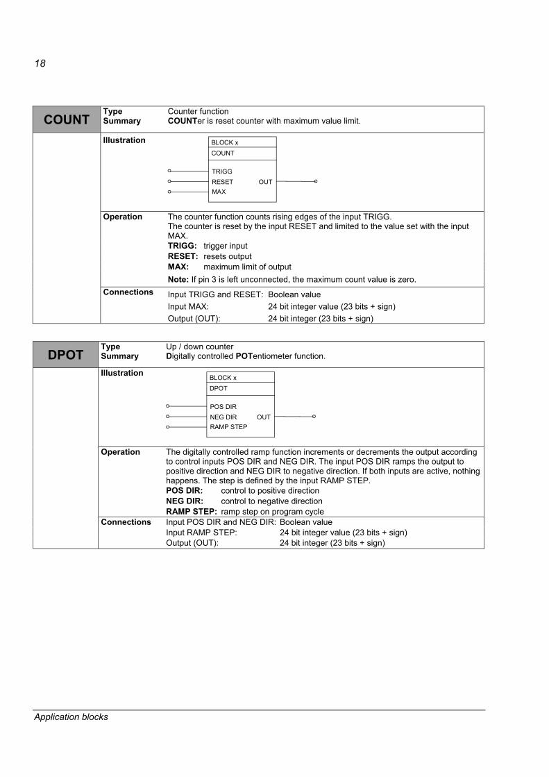
COUNT Type Summary
Counter function COUNTer is reset counter with maximum value limit.
Illustration BLOCK x COUNT
TRIGGRESETMAX
OUT
The counter function counts rising edges of the input TRIGG. The counter is reset by the input RESET and limited to the value set with the input MAX. TRIGG: trigger input RESET: resets output MAX: maximum limit of output
Operation
Note: If pin 3 is left unconnected, the maximum count value is zero.
Input TRIGG and RESET: Boolean value Input MAX: 24 bit integer value (23 bits + sign)
Connections
Output (OUT): 24 bit integer (23 bits + sign)
DPOT Type Summary
Up / down counter Digitally controlled POTentiometer function.
Illustration BLOCK x DPOT
POS DIRNEG DIRRAMP STEP
OUT
The digitally controlled ramp function increments or decrements the output according to control inputs POS DIR and NEG DIR. The input POS DIR ramps the output to positive direction and NEG DIR to negative direction. If both inputs are active, nothing happens. The step is defined by the input RAMP STEP. POS DIR: control to positive direction NEG DIR: control to negative direction
Operation
RAMP STEP: ramp step on program cycle Input POS DIR and NEG DIR: Boolean value Input RAMP STEP: 24 bit integer value (23 bits + sign)
Connections
Output (OUT): 24 bit integer (23 bits + sign)
Application blocks

19
EVENT Type Summary
Event function Application based alarm or fault EVENT
Illustration BLOCK x EVENT
INPUTTEXT PARTYPE
OUT
Operation The EVENT block is used to write an event to the alarm or fault logger. A fault event will trig a drive fault and trip the drive. Alarm events are reflected in the drive status word alarm bit. INPUT triggers the event. Input TEXT PAR selects the parameter index from which the event message (text string) is read. Selects the parameter index from which the event message (text string) is read. Use text parameters 53.11�53.24 for user's application specific texts. Type the respective text by clicking the pin with shift pressed. Input TYPE selects the type of the event (warning or fault). Maximum number of EVENT blocks is 7. See string type of parameters 53.11 STRING 1�53.17 STRING 7.
INPUT TEXT PAR TYPE Cause 0 -> 1 Block activates the event 0 Block deactivates the event TEXT PAR Contents of the event message 0 Type of event: warning 1 Type of event: fault
Inputs INPUT, TEXT PAR: 24 bit integer values (23 bits + sign) Connections Input TYPE: String (compulsory)
FILTER Type Summary
Filtering function. The FILTER block is used as a first order low pass filter for integer values.
Illustration BLOCK x FILTER
INPUT
TIMEOUT
Operation The output is the filtered value of INPUT. Input TIME is the filtering time constant. OUT = INPUT * (1 - e-t/TIME) Note: The internal calculation uses 48 bits accuracy to avoid offset errors. Input: 24 bit integer value (23 bits + sign) Time: 24 bit integer value (23 bits + sign). One corresponds to 1 ms.
Connections
Output (OUT): 24 bit integer (23 bits + sign)
Application blocks

20
MAX Type Summary
Comparative function: maximum selector MAX (MAXimum selector) is used to select the highest value of inputs to the output.
Illustration BLOCK x MAX
I1I2I3
OUT
Operation The values at the inputs I1, I2 and I3 are compared and the highest value is written to the output OUT. OUT = MAX (I1, I2, I3) Input I1, I2 and I3: 24 bit integer values (23 bits + sign) Connections Output (OUT): 24 bit integer (23 bits + sign)
MIN Type Summary
Comparative function: minimum selector MIN (MINimum selector) is used to select the lowest value of inputs to the output.
Illustration BLOCK x MIN
I1I2I3
OUT
Operation The values at the inputs I1, I2 and I3 are compared and the lowest value is written to the output OUT. OUT = MIN (I1, I2, I3) Input I1, I2 and I3: 24 bit integer (23 bits + sign) Connections Output (OUT): 24 bit integer (23 bits + sign)
MULDIV Type Summary
Arithmetic function MULtiplayer DIVider element is used to scale an integer value by dividing the product of two integers with third value.
Illustration BLOCK x MULDIV
INPUTMULDIV
OUT
Operation The output is the product of INPUT multiplied by MUL and divided by DIV. OUT = (INPUT * MUL) / DIV Inputs INPUT, MUL and DIV: 24 bit integer values (23 bits + sign) Connections Output (OUT): 24 bit integer (23 bits + sign)
Application blocks

21
OR Type Summary
Logical function OR is used to form general combinatory expressions with Boolean variables.
Illustration BLOCK x OR
I1I2I3
OUT
Operation The output is true if any of the inputs is true. Truth table:
I1 I2 I3 OUT (binary) OUT (value on display) 0 0 0 False (all bits 0) 0 0 0 1 True (all bits 1) -1 0 1 0 True (all bits 1) -1 0 1 1 True (all bits 1) -1 1 0 0 True (all bits 1) -1 1 1 0 True (all bits 1) -1 1 1 1 True (all bits 1) -1
Input I1, I2 and I3: Boolean values Connections Output (OUT): 24 bit integer value (packed Boolean)
PI Type Summary
PI controller Proportional Integrating block is used as a standard PI-regulator for serial compensation in closed loop systems.
Illustration BLOCK x PI
INPUTKI
OUT
Operation The output is INPUT multiplied by input K/100 plus integrated INPUT multiplied by input I/100.
OUT = INPUT * K / 100 + ( I / 100 ) * INPUT Note: The internal calculation uses 48 bits accuracy to avoid offset errors. Input: 24 bit integer value (23 bit + sign) Input K:
24 bit integer value (23 bit + sign) Gain factor 100 correspond to 1. 10 000 corresponds to 100.
Input I:
Integrator coefficient. 100 correspond to 1. 10 000 corresponds to 100.
Connections
Output (OUT):24 bit integer (23 bits + sign). The range is limited to �10000�10000.
Application blocks

22
PI-BAL Type
Initialisation block for the PI controller.
Illustration BLOCK x PI-BAL
BAL
BAL REF
Operation The block initialises the PI block first. When input BAL is true, the block writes the value of BAL REF to the output of the PI block. When input BAL becomes false, the block releases the output of the PI controller block which continues normal operation from the set output. Note: The block may be used only with the PI block. The execution of block must be after the PI block. Input BAL: Boolean value Connections Input BAL REF: 24 bit integer value (23 bits + sign)
RAMP Type Summary
Ramp function The ramp (RAMP generator) function is used to limit the rate of change of a signal.
Illustration BLOCK x RAMP
INPUTSTEP+STEP-
OUT
Operation The step value is added every program cycle to the OUT value as long as: INPUT - OUT > = STEP+ (positive direction) INPUT - OUT < = -STEP- (negative direction) The ramp step is defined: Input STEP+: positive direction (INPUT + STEP+) Input STEP-: negative direction (INPUT � STEP-) Inputs INPUT, STEP+ and STEP-: 24 bit integer value (23 bits + sign) Connections Output (OUT): 24 bit integer (23 bits + sign)
Application blocks

23
SR Type Summary
Logical function The memory block SR (Set Reset memory) is used as a memory for Boolean variables.
Illustration BLOCK x SR
SETRESETRESET
OUT
Operation Input SET sets and RESET inputs reset the output. If input SET and both RESET inputs are false, the current value remains at the output. If input SET is true and both RESET inputs are false, the output is true. If one or both of the RESET inputs is true, the output is false.
SET RESET RESET OUT (binary) OUT (value on display) 0 0 0 Output Output 0 0 1 False (all bits 0) 0 0 1 0 False (all bits 0) 0 0 1 1 False (all bits 0) 0 1 0 0 True (all bits 1) -1 1 0 1 False (all bits 0) 0 1 1 0 False (all bits 0) 0 1 1 1 False (all bits 0) 0
Inputs SET and both RESET: Boolean values Connections Output (OUT): 24 bit integer value (23 bits + sign)
Application blocks

24
SWITCH-B Type Summary
Logical function Changeover SWITCH for Boolean type of data.
Illustration BLOCK x SW-CB
ACTNONC
OUT
Operation The OUT is equal to input NO (Normally Open) if input ACT is true and equal to input NC (Normally Closed) if input ACT is false.
ACT NO NC OUT OUT (value on display) 0 I2 I3 I3 True = -1 1 I2 I3 I2 False = 0
NO = normally open, NC = normally closed Input ACT, NO and NC: Boolean values Connections Output (OUT): 24 bit integer value (packed Boolean)
SWITCH-I Type Summary
Logical function Changeover SWITCH for Integer type of data.
Illustration BLOCK x SW-IL
ACTNONC
OUT
Operation The OUT is equal to input NO if input ACT is true and equal to input NC if input ACT is false.
ACT NO NC OUT 0 NO NC NC 1 NO NC NO
NO = normally open, NC = normally closed Input ACT: Boolean value Input NO and NC: 24 bit integer values (23 bits + sign)
Connections
Output (OUT): 24 bit integer value (23 bits + sign)
Application blocks

25
TOFF Type Summary
Timing function Time delay OFF (TOFF) is used for Boolean off state delay.
Illustration BLOCK x TOFF
INPUT
TDOUT
Operation The output OUT is true when INPUT is true. The output is false when INPUT has been false for a time equal or longer than input TD.
INPUT
t
1
0Input TD
OUT
t
All bits 1
All bits 0
Input TD
Values on display: True = -1, false = 0.
INPUT: Boolean value Input TD: 24 bit integer value (23 bits + sign). One corresponds to 1 ms.
Connections
Output (OUT): 24 bit integer value (packed Boolean)
Application blocks

26
TON Type Summary
Timing function Time delay ON (TON) is used for Boolean on state delay.
Illustration BLOCK x TON
INPUT
TDOUT
Operation The output OUT is true when INPUT has been true for a time equal or longer than input TD. The output is false when the INPUT is false.
INPUT
time
1
0 Input TD Input TD
OUT
time
All bit s 1 All bit s 0
Values on display: True = -1, false = 0.
INPUT: Boolean value Input TD: 24 bit integer value (23 bits + sign). 1 corresponds to 1 ms.
Connections
Output (OUT): 24 bit integer value (packed Boolean)
Application blocks

27
TRIGG Type Summary
Timing function This block is used for reducing impulse times at the start of automatic procedures and for calculating functions.
Illustration BLOCK x TRIGG
I1I2I3
OUT
Operation The rising edge of input I1 sets the output bit 0 for one program cycle. The rising edge of input I2 sets the output bit 1 for one program cycle. The rising edge of input I3 sets the output bit 2 for one program cycle.
Input I1
t
1
0Output, Bit 0
t
1
0Tc
Example
Tc
Tc = Programcycle time
Input I1, I2 and I3: Boolean values Connections Output (OUT): 24 bit integer value (23 bits + sign)
Application blocks

28
WR-I Type Summary
Write integer value to the parameter in the RAM memory of the control board.
Illustration BLOCK x WR-I
GROUPINDEXIN
OUT
Operation This function writes an integer value to the integer type of AMC table index. Note: The function does not take care if another device e.g. field bus is writing to the same place. This causes oscillation of signal. It is not possible to write into the middle of the reference chain. Check the parameter type (I or PB) from the Firmware manual. Inputs GROUP, INDEX and IN: 24 bit integer value (23 bits + sign) Connections Input GROUP: Parameter group number
Input INDEX: Parameter index number Input IN: Data input pin to read new value for the parameter Output (OUT): Error code (24 bit integer value) Error codes:
0 successful write 131073 group protected 131074 index protected 131075 illegal group 131076 undefined group 131077 illegal index 131078 undefined index 131079 illegal format 131080 min max limitation 131088 illegal selection
For example parameter 20.04 MAXIMUM CURRENT - group is 20 - index is 04
Application blocks

29
WR-PB Type Summary
Write packed Boolean value to the parameter in the RAM memory of the control board.
Illustration BLOCK x WR-PB
GROUPINDEXIN
OUT
Operation Writes a packed Boolean value to the packed Boolean type of AMC table index e.g. command word. Note: The function does not take care if another device e.g. field bus is writing to the same place. This causes oscillation of signal. Check the parameter type (I or PB) from the Firmware manual. Inputs GROUP, INDEX and IN: 24 bit integer value (23 bits + sign) Connections Input GROUP: Parameter group number
Input INDEX: Parameter index number Input IN: Data input pin to read new value for the parameter Output (OUT): Error code (24 bit integer value) Error codes:
0 successful write 131073 group protected 131074 index protected 131075 illegal group 131076 undefined group 131077 illegal index 131078 undefined index 131079 illegal format 131080 min max limitation 131088 illegal selection
For example parameter 20.04 MAXIMUM CURRENT - group is 20 - index is 04
Application blocks

30
XOR Type Summary
Logical function XOR (eXclusive OR) is used to generate combinatory expressions with Boolean variables.
Illustration BLOCK x XOR
I1I2I3
OUT
Operation The output is true if only one or all connected inputs are true. Otherwise the output is false. Truth table:
I1 I2 I3 OUT (binary) OUT (value on display) 0 0 0 False (all bits 0) 0 0 0 1 True (all bits 1) -1 0 1 0 True (all bits 1) -1 0 1 1 False (all bits 0) 0 1 0 0 True (all bits 1) -1 1 0 1 False (all bits 0) 0 1 1 0 False (all bits 0) 0 1 1 1 True (all bits 1) -1
Input I1, I2 and I3: Boolean values Connections Output (OUT): 24 bit integer value (packed Boolean)
Application blocks

31
I/O and communication blocks Execution time interval of these blocks has not relation with execution time of Function blocks.
AI1 Type Summary
Analogue input 1 This block is used to read analogue input 1 (AI1) of RMIO motor control- and I/O board. Resolution is 10 bits + sign, voltage type of input.
Execution interval is 10 ms.
Illustration AI1
MIN
FILT
X21:3-4
13.12
13.03
1.19
Operation FILT: See parameter 13.03 AI1 FILTER ms. A filtering time constant for AI1. OUT: See signal 1.19 AI1 [V] 10 V == 10000
Note: Parameters 13.01 and 13.02 have no effect at the output. Input FILT: Real value 0�30000 ms Connections Output OUT: Real value on range �20000�20000
AI2 Type Summary
Analogue input AI2 This block is used to read analogue input 2 (AI2) of RMIO motor control and I/O board. Resolution is 10 bits + sign, current type of input 0(4)...20 mA.
Execution interval is 10 ms.
Illustration AI2
MIN
FILT
X21:5-6
13.06
13.07
1.20
MIN: See parameter 13.06 MINIMUM AI2. 1 = 0 mA / 0 V 2 = 4 mA / 2 V 3 = -20 mA / -10 V
FILT: A filtering time constant [ms] for AI2. OUT: See signal 1.20 AI2
20000 == 20 mA, 2 V or 10 V
Note: Parameters 13.04 and 13.05 have no effect at the output. Input MIN: Integer value 1�3 Input FILTER ms: Integer value 0�30000
Connections
Output (OUT): Integer value on range �20000�20000
Application blocks
32
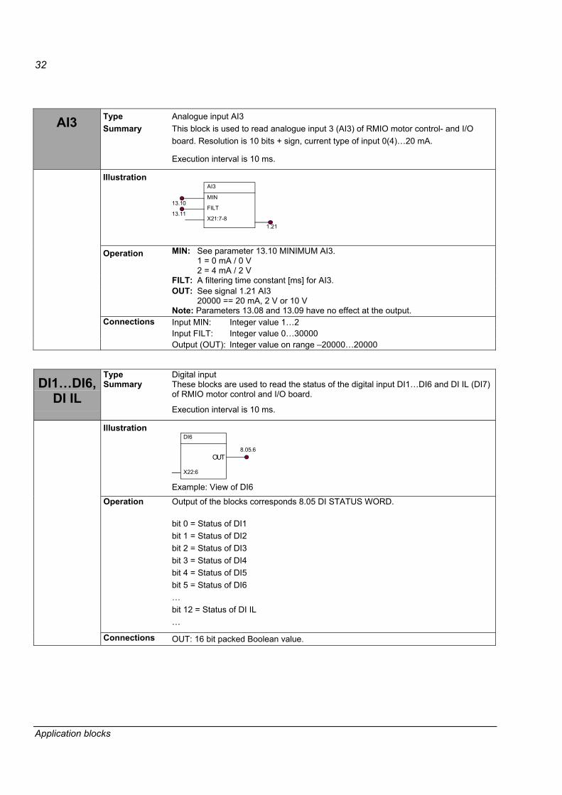
AI3 Type Summary
Analogue input AI3 This block is used to read analogue input 3 (AI3) of RMIO motor control- and I/O board. Resolution is 10 bits + sign, current type of input 0(4)�20 mA.
Execution interval is 10 ms.
Illustration AI3
MIN
FILT
X21:7-8
13.10
13.11
1.21
MIN: See parameter 13.10 MINIMUM AI3. 1 = 0 mA / 0 V 2 = 4 mA / 2 V
FILT: A filtering time constant [ms] for AI3. OUT: See signal 1.21 AI3
20000 == 20 mA, 2 V or 10 V
Operation
Note: Parameters 13.08 and 13.09 have no effect at the output. Input MIN: Integer value 1�2 Input FILT: Integer value 0�30000
Connections
Output (OUT): Integer value on range �20000�20000
DI1�DI6, DI IL
Type Summary
Digital input These blocks are used to read the status of the digital input DI1�DI6 and DI IL (DI7) of RMIO motor control and I/O board.
Execution interval is 10 ms.
Illustration DI6
X22:6
OUT8.05.6
Example: View of DI6
Operation Output of the blocks corresponds 8.05 DI STATUS WORD. bit 0 = Status of DI1 bit 1 = Status of DI2 bit 2 = Status of DI3 bit 3 = Status of DI4 bit 4 = Status of DI5 bit 5 = Status of DI6 � bit 12 = Status of DI IL �
Connections OUT: 16 bit packed Boolean value.
Application blocks

33
EXT1 DI�DI3
Type Summary
Extension module 1 digital inputs This block is used to read status of the digital inputs DI1�DI3 of digital extension module 1 (DI/O EXT1).
Execution interval is 10 ms.
Illustration EXT1 DI1
X11:1-2
OUT8.05.6
EXT1 DI2
X12:1-2
OUT8.05.7
EXT1 DI3
X11:3-4
OUT8.05.8
Operation Output is same as 8.05 DI STATUS WORD bits 6�8. � bit 6 = Status of EXT1 DI/O DI1 bit 7 = Status of EXT1 DI/O DI2 bit 8 = Status of EXT1 DI/O DI3 �
Connections OUT: 16 bit packed Boolean value.
EXT2 DI�DI3
Type Summary
Extension module 2 digital inputs: EXT2 DI1, EXT2 DI2 and EXT2 DI3. This block is used to read status of the digital inputs DI1�DI3 of digital extension module 2 (DI/O EXT2).
Execution interval is 10 ms.
Illustration EXT2 DI1
X11:1-2
OUT8.05.9
EXT2 DI2
X12:1-2
OUT8.05.10
EXT2 DI3
X11:3-4
OUT8.05.11
Operation Output is same as 8.05 DI STATUS WORD bits 9�11. � bit 9 = Status of EXT2 DI/O DI1 bit 10 = Status of EXT2 DI/O DI2 bit 11 = Status of EXT2 DI/O DI3 �
Connections OUT: 16 bit packed Boolean value.
Application blocks

34
EXT2 AI1�AI2
Type Summary
Extension analogue inputs This block is used to read analogue input 1 and 2 (AI1, AI2) of analogue extension module (AI/O EXT2).
Execution interval is 10 ms.
Illustration EXT2 AI1
MODE
CONV
X1:1-2
13.13
98.13
1.41FILT
13.14
EXT2 AI2
MODE
CONV
X1:3-4
13.15
98.14
1.425FILT
13.16
MODE: 1 = UNIPOLAR 2 = BIPOLAR
See parameter 98.13 AI1 EXT2 MODE and 98.14 AI2 EXT2 MODE in the Firmware manual of System Application program. unipolar input mode bipolar input mode
CONV: See parameter 13.13 EXT2 AI1 CONV MODE and 13.14 EXT2 AI2 CONV MODE, the conversion mode for the analogue input EXT2 AI1 and EXT2 AI2.
The modes are: 1 = NORMAL scale �20 mA, -2 V, -10 V�0�+10 V, +2 V, -20 mA =
-2000�+20000 2 = 4 mA scale 4�20 mA = 0�20000 3 = Pt-100 supply from any AO, scale 200 C = 20000
1xPt-100: supply 10 mA 2xPt-100: supply 5 mA 3xPt-100: supply 3.3 mA
FILTER ms: See parameter 13.14 EXT2 AI1 FILTER and 13.16 EXT2 AI2 FILTER. A filtering time constant for AIx.
Operation
OUT: See signal 1.41 EXT2 AI1 and 1.42 EXT2 AI2. Input MODE: Integer value 1�2 Input CONV: Integer value 1�3 Input FILT: Integer value 0�30000 Output (OUT): Integer value on range �20000�20000
Connections
HW settings: See Analogue I/O Extension User�s Manual RAIO-0 (3AFE64484567 [English]).
Application blocks
35
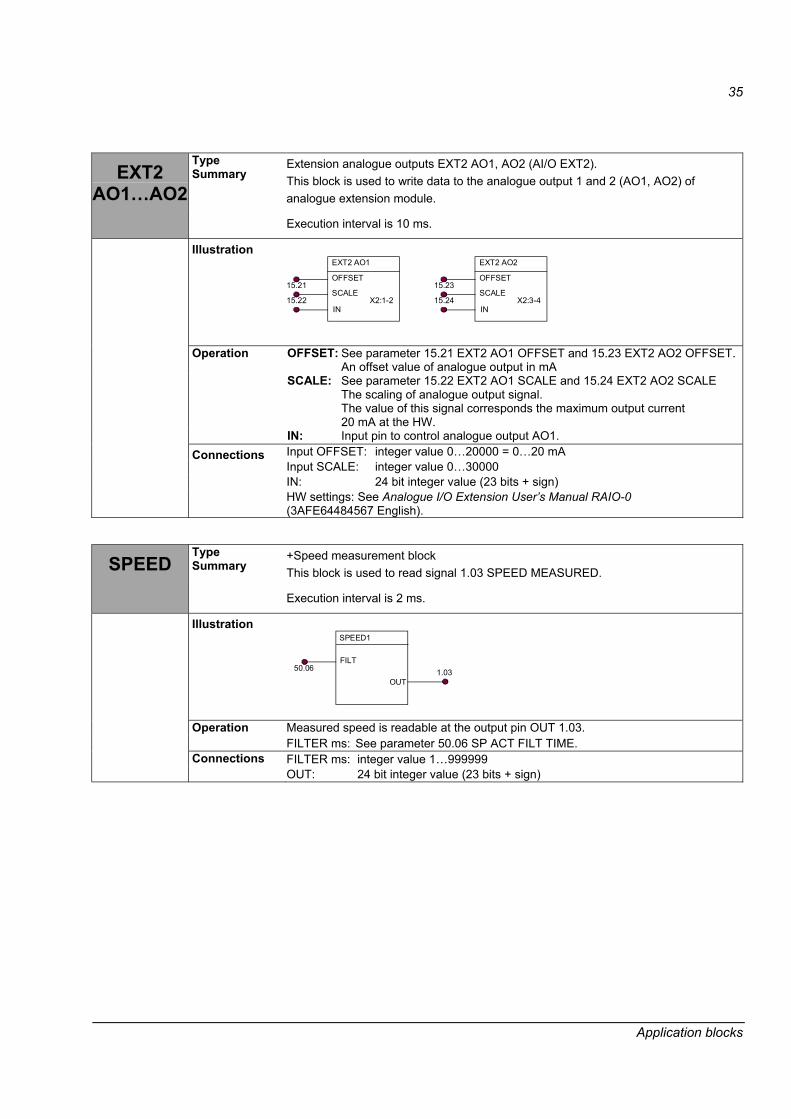
EXT2 AO1�AO2
Type Summary
Extension analogue outputs EXT2 AO1, AO2 (AI/O EXT2). This block is used to write data to the analogue output 1 and 2 (AO1, AO2) of analogue extension module.
Execution interval is 10 ms.
Illustration EXT2 AO1
15.22
15.21OFFSET
SCALE
IN
EXT2 AO2
15.24
15.23OFFSET
SCALE
INX2:1-2 X2:3-4
OFFSET: See parameter 15.21 EXT2 AO1 OFFSET and 15.23 EXT2 AO2 OFFSET.An offset value of analogue output in mA
SCALE: See parameter 15.22 EXT2 AO1 SCALE and 15.24 EXT2 AO2 SCALE The scaling of analogue output signal. The value of this signal corresponds the maximum output current 20 mA at the HW.
Operation
IN: Input pin to control analogue output AO1. Input OFFSET: integer value 0�20000 = 0�20 mA Input SCALE: integer value 0�30000 IN: 24 bit integer value (23 bits + sign)
Connections
HW settings: See Analogue I/O Extension User�s Manual RAIO-0 (3AFE64484567 English).
SPEED Type Summary
+Speed measurement block This block is used to read signal 1.03 SPEED MEASURED.
Execution interval is 2 ms.
Illustration SPEED1
FILT
OUT1.0350.06
Measured speed is readable at the output pin OUT 1.03. Operation FILTER ms: See parameter 50.06 SP ACT FILT TIME. FILTER ms: integer value 1�999999 Connections OUT: 24 bit integer value (23 bits + sign)
Application blocks

36
START Type Summary
Start block This block is used to start / stop the drive in I/O control mode (par. 98.02 = NO).
Execution interval is 10 ms.
Illustration START
IN
This start command is connected parallel (OR) with IO-start command by parameter 10.01 START/STOP.
Operation
Input IN: TRUE = start, FALSE = stop Connections IN: Boolean value
SUB Type Summary
Arithmetic subtraction function.
Illustration BLOCK x ADD
ADD1ADD2ADD3
OUT
Subtraction can be implemented by using ADD block in which the subtracter input is inverted (multiplied by -1). OUT = ADD1 + (-ADD2) + (-ADD3) Example: ADD1 = 3000 ADD2 = 1000 (inverted in Connect Pin window of DriveAP) ADD3 = 0 (inverted in Connect Pin window of DriveAP) OUT = ADD1 + (-ADD2) + (-ADD3)
Operation
2000 = 3000 + (- 1000) + (-0) Input ADD1, ADD2 and ADD3: 24 bit integer values (23 bits + sign) Connections Output (OUT): 24 bit integer (23 bits + sign)
Application blocks

37
Application blocks

3AFE
6842
0075
Rev
A /
EN
EFFE
CTI
VE: 0
5.11
.200
4
ABB Oy AC Drives P.O.Box 184 FI-00381 HELSINKI FINLAND Telephone + 358 10 22 11 Fax + 358 10 22 23380 Internet http://www.abb.com