appendix: forest road measurements in the tropics978-3-540-46393-1/1.pdf · appendix: forest road...
TRANSCRIPT

Appendix: Forest Road Measurements in the Tropics
A variety of analog and digital tools are available for road and landscapemeasurements in forested road environments. Tropical forested climates indeveloping countries, however, pose unique challenges to collecting field meas-urements. Climate conditions are often humid and may be subject to short orlong periods of intense rain. Humidity and exposure to rainy conditions maydamage sensitive optical equipment and periods of intense rain may shortenthe number of daylight hours in which measurements can be efficiently col-lected. Vegetation may greatly reduce lines of sight on the ground. As a result,brushing may be needed and can require significant amounts of time. Whenlines of sight are limited, the ability to take measurements over long distancesis also typically reduced and more, shorter-distance measurements will berequired in comparison with traverses in open landscapes. Additional meas-urements will require more frequent moving and repositioning of equipment.For optically based devices, leveling of the instrument at every new position isusually required and requires operator time. Regardless of the type of meas-urement device, the opportunity for measurement errors or blunders increasesas the number of movements and equipment setups increase.
An additional challenge in tropical areas is access to electrical power. Manyforms of modern digital equipment require that power be available in order tooperate. The power may be supplied by an internal or removable battery thatwill provide enough electrical current for equipment to operate over a shortperiod. Many equipment manufactures provide internal and external batter-ies that are designed to operate for a typical work day (8 h) before expiring orrequiring a recharge. In the case of rechargeable batteries, access to electricalcurrent will be necessary in order to recharge the battery. In some cases inwhich access to electrical current is limited and the voltage of the battery isrelatively low, it is possible to use a solar-powered device to recharge a battery.Digital equipment that use an internal (nonremovable) battery may poseadditional constraints on measurement activities as exchanging of batteries isdifficult or not possible.
A.1Analog Location Measurement Tools
Analog forest measurement tools are still in prevalent use throughout theworld owing to their ability to operate in almost any setting and also for theirnonreliance on power sources. Analog devices for measuring directions(azimuths or bearings) or angles between objects include the hand compass,staff compass, transit, and theodolite. The hand compass and staff compass areboth capable of establishing a direction between objects and rely on the Earth’smagnetic field for measurements. Although the hand compass is accurate toabout 2˚, the staff compass can likely determine direction to about 1˚ whenused properly but is considerably more expensive (about US $450 for a qualitystaff compass compared with US $75 for a hand compass). Both the hand com-pass and the staff compass will measure the magnetic azimuth or bearing of adirection unless the user adjusts the compass dial to account for magnetic vari-ation. Magnetic variation is the angular distance at any location on the Earthbetween true north and the orientation of the Earth’s magnetic field. Magneticvariation can range from 0˚ to well over 20˚ in tropical areas. In addition, thesemanual compasses will be subject to local attraction. Local attraction occurswhen a compass needle is directed toward or away from an object that inter-feres with the magnetic field. Local attraction can be caused by a mineraldeposit, a vehicle, or a mechanical pencil in a nearby shirt pocket. The risk ofrecording directions influenced by local attraction can be minimized by takingfore azimuths and back azimuths and comparing the two measurements. Afteraccounting for a 180˚ difference, the measurements should be approximatelyequal. If not, local attraction may be occurring.
Transits and theodolites are predecessors of the modern-day digital total station (discussed later) and rely on the user establishing a starting azimuth orbearing through an initial back sight. Directions between subsequent objects canbe derived by forming a continuous traverse such that all objects are connectedto each other through a series of back sights and fore sights. The angular resolu-tion of a typical transit is approximately 20–30′, while some theodolites have resolutions as fine as 0.1′. Theodolites can be thought of as a high-precision transit and have evolved into digital measurement equipment. Both transits andtheodolites require mounting on a fixed tripod or other firm surface that can beleveled and operator skill. A transit costs about US $1,200, while an opticaltheodolite would cost about US $1,600.
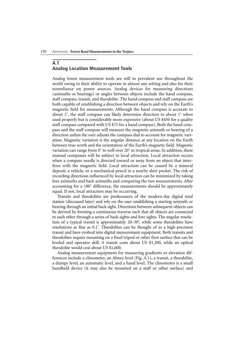
Analog measurement equipment for measuring gradients or elevation dif-ferences include a clinometer, an Abney level (Fig. A.1), a transit, a theodolite,a dumpy level, an automatic level, and a hand level. The clinomoter is a smallhandheld device (it may also be mounted on a staff or other surface) and
150 APPENDIX: Forest Road Measurements in the Tropics

provides a convenient method of measuring gradients from the user’s eyeto any object. Typical angular resolution of a clinometer is about 1–2˚ and thepurchase price would be about US $100. The Abney level, similarly to theclinometer, is a handheld instrument, but is capable of greater precision inmeasuring angles, with resolutions reaching 10′ and has a slightly higher pur-chase price of about US $130. Transits and theodolites are also capable of meas-uring gradients with a precision of 1′ and 0.1′, respectively. The automatic levelis used to determine elevation differences between objects and requires mount-ing on a tripod. The process of using an automatic level to determine elevationdifference is known as differential leveling. Although an operator can start froma known or an assumed elevation benchmark, it is the elevation differencesbetween features that determine their height relationships to one another. Theautomatic level requires two people to operate it efficiently; one person uses thelevel instrument to sight on a level rod, while the other person holds the rodvertically. Level rods contain graduated readings of typically 0.01 m on them –these markings determine the precision at which the automatic level can deter-mine elevation differences. A hand level can be used in a similar manner to anautomatic level but typically is attached at a fixed height to a staff. The hand-level operator reads elevations from a level rod placed on an object; differencesbetween the fixed height of the hand level and level rod determine elevations.
Analog approaches for measuring distances include measurement tapes andpacing. Coiled steel tapes may provide the most reliable method of measuringdistances without digital tools. These tapes are sometimes referred to asengineer’s or surveyor’s tapes and are also available in fiberglass. Metric steel
A.1 Analog Location Measurement Tools 151
MAIN CAPSTAN BOLT
LIMB
PERCENT TEMPLATE
LOCK NUT SCREW
LIMB CAPSTAN NUT
FRONT VIEW
VIAL BRACKET
LEVEL VIAL
TELESCOPE TUBESLIDE TUBE
REAR VIEW
Fig. A.1. The Abney level (From Waldbridge 1990)

tapes come in size increments of 15, 30, or 50 m and are typically graduated inmeters and decimeters, occasionally in millimeters. Using an engineer’s tapetypically involves two people and team coordination to ensure that the ends ofthe tape are positioned precisely between or over objects (with assistance fromplumb bobs) from which distances are desired. The tape must be held level andstraight to capture accurate distances, and it is relatively easy to snap or breaka tape should a kink develop. Steel tapes are subject to rust and should be wipedclean following use. String boxes are a low-cost method for measuring distanceby measuring the length of string that passes around a measuring wheel.The string is tied to a bush and the slope distance is displayed on the counter onthe device as the person walks. They can be used to for a variety of tasks, includ-ing curve layout. It is a simple, rugged tool that will allow individuals to meas-ure distance by themselves. Pacing is a less reliable than taping for measuringdistances but offers the advantage of convenience. A person’s average pacelength can be estimated by establishing a measurement course through topog-raphy that is similar to that in which measurements are to be taken. The personwalks the course several times using a pace that is relaxed and can be maintainedthrough an entire day. The total length walked is divided by the total number ofpaces to derive an average distance per pace. This average can then be used toapproximate distance measurements in the field.
A.2Digital Location Measurement Tools
There are many types of digital measurement tools that are available for roadoperations in forested environments. These tools range from handheld devicessuch as digital range finders, to aerial-based platforms such as LiDAR, to space-based systems that are capable of taking imagery of the Earth’s surface.Choosing the appropriate digital tool for road-related measurements willinvolve many considerations, including cost, time constraints, accuracyrequirements, topography, and access to power sources. Digital measurementtools are capable of great time savings in taking and recording measurements;many digital measurement tools are capable of automatically saving meas-urements to a personal digital device or data collector. This capability removesthe need for transferring measurements from a field notebook to a computerfollowing data collection, a process that has a high likelihood of introducingerrors. Conversely, digital measurement tools are often fragile and require ahigh level of expertise to operate comfortably. Should a device stop working inthe field or in the air if it is based on an aerial platform, owing to power loss,damage, or other reason, measurement work must often cease unless a backupdevice exists or the difficulty can be resolved. In addition, should a digital
152 APPENDIX: Forest Road Measurements in the Tropics
instrument that is recording measurement data stop functioning, there is alsothe question of whether collected data can be retrieved from the device.Nonetheless, technological advancements continue to result in the developmentof digital tools and techniques for forest measurements, leading to greatereconomy, reliability, and performance for consumers.
Digital range finders have become a widely used tool in forest measurementapplications. Most digital range finders operate by emitting a laser pulse from ahandheld device and measuring the amount of time it takes the pulse to return.The elapsed time is then used with the speed of light to determine a distance.Some range finders use sound waves rather than light pulses. Many digital rangefinders do not require a reflective surface for the emitted laser but a reflective tapemay help in areas that are densely forested. Range finders are capable of distancemeasurements within several millimeters of actual distances but there are consid-erable performance issues between types. In addition, many range finders are alsocapable of deriving slope distances, vertical angles, tree heights, and distancesbetween two objects that are within visible range. Some range finders can work intandem with a data collector to automatically download measurements to a data-base. Digital compasses have also been developed to provide a directional meas-urement device for use in tandem with digital range finders. The advantage ofsuch a combined system would be that users could measure both directions anddistances between objects through traverses. Digital compass technology, however,appears to not be reliable for directional measurements but improvements willlikely occur in the near future.
Global Positioning System (GPS) measurement applications have been asource of frustration for those wishing to apply this technology for forestoperations but there is recent evidence that some GPS receivers are capable ofreliably collecting measurements under canopy in certain conditions. The lim-iting factor for GPS applications in forestry has been that lines of sight betweenGPS receivers on the ground and space-based satellite systems are often limitedby canopy conditions, topographic barriers, or some combination thereof.A GPS receiver calculates a position by being able to receive signals from at leastfour satellites, with more satellites leading to better data collection opportuni-ties. The GPS receiver can use information included in the signals to calculatethe range (distance) between the receiver and each satellite it communicateswith. These ranges are used to estimate a position through trilateration.
Satellite signal quality and reliability for measurement determination isreliant on satellite availability and the geometry of the available satellites inrelation to the GPS receiver. Potential satellite signal quality can be estimatedas a position dilution of precision (PDOP) statistic. Mission planning softwarefor GPS is used to calculate an expected PDOP value for a field site andcan identify preferred times for collecting data. Larger values of PDOP inferdiminished satellite geometry and measurement reliability.
A.2 Digital Location Measurement Tools 153

Potential sources of variability and error for GPS measurements includeatmospheric interference of satellite signals, timing errors between satellitesand the GPS receiver, the rotation of the Earth, and orbital satellite patterns.A portion of these errors, in some cases considerable, can be estimated andremoved through the process of differential correction. Differential correctioninvolves having a fixed GPS base station at a known location that continuouslycompares GPS-derived positions to its known position. GPS base stations arelocated using very accurate and precise measurements. The difference betweenthe known location and the GPS-derived locations is a correction factor thatcan also be applied to other GPS receivers that are collecting measurementsnearby.
Another way in which to reduce errors is to collect multiple measurementsat single locations. Given the number of potential errors, a coordinate deter-mination based on the average of multiple measurements should be morestatistically reliable than that based on one measurement.
In addition to the difficulty in receiving satellite signals in forested moun-tainous terrain, there was only one satellite system available to users worldwideuntil recently. The primary satellite system for GPS measurements is the NAVSTAR (Navigation Satellite Tracking and Ranging) system operated by the US Department of Defense. NAVSTAR became available in the early 1980sand has 24 operational satellites with satellite signals freely and continu-ously available to GPS users worldwide. NAVSTAR satellite signals wereintentionally scrambled, under a procedure known as selective availability, inthis system until 2001 and could lead to measurement errors of 100 m or more.Since 2001, selective availability has been removed and several new satellitesyztems have become operational. There is no guarantee however, that selectiveavailability will remain off in the future.
In addition to NAVSTAR, there are now space-based augmentation systems(SBAS) that are capable of providing conventional real-time differential cor-rections to GPS receivers as they collect data. Conventional real-time differen-tial uses the more accessible coarse/acquisition (C/A) satellite signals ratherthan phase code signals. Although phase code signals possess greater potentialfor accurate GPS measurements, continuous and uninterrupted satellite signalsare necessary, a condition that is not always available under forest canopy. SBASderives measurement correction factors for several potential GPS error sources,including atmospheric interference of signals, time sequences for satellite sig-nal range (distance) estimates, and satellite orbital patterns. The primary SBASfor many users is the US Federal Aviation Administration’s Wide AreaAugmentation System (WAAS), which has three operational satellites as of2006 and more satellites are expected in the near future. A single WAAS satel-lite signal is required for a GPS receiver to apply real-time correction factorsbut reception from additional WAAS satellite signals is preferred as they
154 APPENDIX: Forest Road Measurements in the Tropics

provide a backup should reception from one satellite become unavailable.There are also other SBAS, including the European Geostationary NavigationOverlay System (EGNOS) and the Japanese MTSAT satellite-based augmenta-tion system (MSAS). Some GPS can operate with all SBAS.
Other GPS systems include GLONASS (Global Navigation Satellite System),which was developed by the Russian military. GLONASS was made fully oper-ational with 24 satellites in 1996 but has been subject to irregularity in thenumber of operational satellites. A system under the guidance of the EuropeanSpace Agency called Galileo is expected to be operational in 2008.
GPS receivers can be partitioned by measurement accuracy and price intothree broad grades or categories: survey, mapping, and consumer. Measurementaccuracy can be thought of as the difference between a GPS-collected measure-ment and the true location of the GPS receiver when it collects a measurement.The most accurate and expensive GPS receivers are called survey grade and canestimate positions within 1 cm of true location when used properly. Survey-grade GPS receivers are full-featured and allow users to differentially correct col-lected data and to work with various satellite systems. Beyond the relatively highcost of survey-grade GPS receivers (typically greater than US $10,000), operatorproficiency is required with hardware and software applications. The use of sur-vey-grade GPS receivers in forested landscapes is ill-advised owing to the deli-cate nature of the equipment and a requirement for continuous adequatesatellite reception in order to derive measurements efficiently. Beyond theseconcerns, the accuracies of survey-grade GPS receivers, even if achievable,are probably greater than those required for most forest road operations.
Mapping-grade or resource-grade GPS receivers represent the second cate-gory of the three GPS receiver categories and can be purchased for between US$2,000 and US $10,000 depending on the features and the manufacturer. Thesetypes of GPS receivers are also sometimes called GIS-grade GPS receivers.Many mapping-grade GPS receivers come with software for differential correc-tion. Manufacturer estimates of positional accuracy are 2–5 m depending onthe receiver and the application for mapping-grade GPS receivers. These esti-mates often reflect best-case data collection scenarios and may not be possiblein forested environments, but several studies have been reported. Positionalaccuracies between 12.3 and 25.6 m during leaf-on conditions and between 3.8and 8.8 m during leaf-off conditions have been reported in a mixed-hardwoodforest during selective availability. Some studies have examined several map-ping-grade receivers under dense hardwood canopy and determined averagepositional errors of 4.0 m. Positional errors have been reported between 0.5and 5.6 m that were influenced by basal area density and data collection timesin Sitka spruce (Picea sitchensis). A nondifferentially corrected mapping-gradeGPS receiver below a partial hardwood forest canopy was used and reportedaccuracies of 20–30 m. Other studies have tested a variety of mapping-grade
A.2 Digital Location Measurement Tools 155
GPS receivers and configurations and reported accuracies between 2.4 and 4.5 munder forest canopy with at least 70% obstruction of the sky in deciduousand red-pine forests.
Consumer-grade GPS receivers are the least accurate and most affordable ofthe GPS grades, with many receivers in this category costing between US $100and US $500. Although the price range is attractive for most budgets, there areseveral disadvantages that must be considered. Consumer-grade GPS receiversusually do not allow operators to set minimum thresholds for satellite signalquality before measurements can be calculated and stored digitally. The major-ity of consumer-grade GPS receivers do not allow a minimum PDOP level tobe set as a quality control for data collection and do not include mission plan-ning software. Some consumer-grade GPS receivers do not enable users to con-duct point averaging to determine a single position. In addition, while mostconsumer-grade GPS receivers afford users the ability to store measurementsindividually, the common storage limit of 500 points for receivers in the severalhundred dollar range makes point averaging impractical. Differential correc-tion capabilities are limited in consumer-grade GPS receivers and must beaccessed through third-party software.
Consumer-grade GPS receiver accuracy in forested settings has beenreported in previous studies. One study investigated the positional accuraciesand reliability of six consumer-grade GPS receivers within several different for-est types and reported measurement accuracies within 10 m of true positionunder dense conifer canopy and within 5 m under partial canopy dependingon the type of consumer-grade GPS receiver. Average accuracies of consumer-grade GPS receivers between 6.5 and 7.1 m under dense primarily hardwoodcanopies have been reported. Although the typical average accuracies reportedby these studies (5–10 m) may be acceptable for some forestry applications, thelimitations of consumer-grade GPS receivers must be considered. These limi-tations include the ability to set minimum satellite quality standards, whetherpoint averaging is possible, and access to differential correction procedures.
A digital total station is capable of highly accurate and precise measurementsof forested features to less than 1 cm from actual locations. Measurement capa-bilities include distances and angles in both horizontal and vertical dimensions,with horizontal angles being the least reliable of the possible measurements. Thetotal station still has few equals for reliable measurements in the forest butrequires a clear line of sight to a reflective surface for distance measurements.The total station is similar to a handheld laser range finder in that a beam oflight is emitted from the instrument, reflects off of a target, and is sensed by areceiving lens. Distances are computed through the amount of time that elapsesduring the light beam’s travel. A reflective prism composed of mirrors and/orglass is often users to provide a reflective target. Some digital total stations canoperate without the use of a reflective target but questions remain as to the
156 APPENDIX: Forest Road Measurements in the Tropics

accuracy of such measurements. Digital total stations can be purchased forapproximately US $6,000–12,000 for manually operated instruments. Robotictotal stations are available for approximately US $30,000. Robotic total stationsallow for remote control of targeting and measurement operations and requireonly one operator (a typical total station crew will involve an instrument oper-ator and someone to position and move the rod upon which the prism isplaced). Consequently, robotic total stations can greatly increase the efficiencyof measurements when only one operator is available.
Considerable care must be taken when using a total station to ensure thatthe instrument is level, that its starting position is known or at an assumedlocation, and that accurate measurement and recording of instrument andprism heights is made. The instrument and prism heights must also beinvolved in any calculations that involve gradients or elevations. Proper totalstation use typically requires an investment of time beyond that required byhandheld range finders and handheld GPS receivers. In comparison, theseother tools are somewhat forgiving and user-friendly, while proper total stationuse requires that operators be well versed in instrument use and data collec-tion, transfer, and data processing routines. Despite these concerns, a totalstation remains perhaps the most reliable instrument for gathering accurateand precise measurement data in forested settings.
Measurements related to forest road operations can also be capturedthrough remote-sensing techniques from aerial-based or space-based plat-forms. Georeferenced color aerial photography can now be collected at resolu-tions finer than 1 m. Aerial platforms for this purpose combine an inertialguidance system with a digital camera system and can provide georeferencedimagery within several hours of a flight.
LiDAR systems can be operated from both aerial platforms and ground-basedlocations. The aerial platform combines a laser emitting–receiving scanningunit, a differential GPS receiver on the ground and on the aerial platform, andan inertial guidance unit to measure various terrain characteristics. Individualtree attributes, forest structure, and detailed topographic measurements can allbe derived from lidar data. One of the most promising products for road oper-ations is the ability of lidar to support the creation of detailed (1-m resolution)digital terrain models. Digital terrain models at this resolution could providevaluable information in road design and planning activities.
Space-based remote-sensing platforms include Landsat Thematic Mapper(TM), IKONOS-2, and SPOT (Système Pour l’Observation de la Terre). LandsatTM represents a system of satellites with the ability to image wide swaths (185 km)of the Earth’s surface in a single orbital pass. Landsat-1 was the first satellite in aseries and was launched in 1972. The most recent, Landsat7, was launched in 1999and can capture imagery in 15-m panchromatic resolution and 30-m multispec-tral resolution. IKONOS-2 is a single satellite and is capable of 1-m resolution for
A.2 Digital Location Measurement Tools 157

panchromatic imagery and 4-m resolution in multispectral imagery. IKONOS ishighly maneuverable and can be redirected to image specific objects on the Earth’ssurface. SPOT was initiated by the French government in 1978 but also had assistance from Sweden and Belgium. SPOT-5 is the latest realization of this effortand captures a 120-km swath of the Earth and is capable of 2.5-m panchromaticresolution and 10-m multispectral resolution. Although the orbits of the SPOTsatellites have regular patterns, the optical system can be directed toward featuresof interest.
A.3Soil Measurement Tools
Several inexpensive tools are available to measure various aspects of soilstrength. The sand cone (Fig. A.2) allows the user to determine the wet and dryunit weight of the soil. A hole is dug in the road subgrade and the soil is collected and weighed to determine the wet unit weight, or it can be dried todetermine the dry unit weight. The volume of the hole is determined by meas-uring the change in weight of the sand-cone device. It is a low-cost reliablemethod used to determine wet and dry unit weights for road subgrades.
The Clegg hammer (Fig. A.3) consists of a tube with a weight that is allowedto freefall inside the tube. The weight contains an accelerometer that resides atthe base of the handle with a triaxial cable that connects the handle to a digitalreadout device. The weight is lifted to the top of the tube and allowed tofreefall, with the accelerometer recording the maximum deceleration rate.Typically, the value after the fourth drop is recorded as the measure of soilstrength.
Dynamic and static cone penetrometers measure the resistance that occursfrom driving a cone into the soil with a fixed forced from a dropping weight orby applying a steady force manually. The resistance measured is displayed on adigital device or a circular dial. Care must be used to keep the device verticaland to not use a jerking motion when applying force to the penetrometer.Correlations between the dynamic cone penetrometer and the Californiabearing ratio and other strength values have been developed for cohesive andnoncohesive soils.
158 APPENDIX: Forest Road Measurements in the Tropics

A.3 Soil Measurement Tools 159
Jar
Cone
Plate
Hole
Fig. A.2. The sand cone
Digital display
Accelerometer
Hammer
Guide tube with wheels
Fig. A.3. The Clegg hammer

References
Burch D (2000) Estimating excavation. Craftsman Book Company, CarlsbadByrne J, Nelson R, Googins P (1960) Logging road handbook: the effect of road design
on hauling costs. USDA Forest Service agricultural handbook 183. USDA ForestService, Washington
Caterpillar (2003) Caterpillar performance handbook CD-ROM, 33rd edn. Caterpillar,Peoria
Dykstra D (1996) FAO model code of forest harvesting practice. FAO, RomeFaiz A, Staffini E (1979) Engineering economics of the maintenance of earth and gravel
roads. Transportation record 702, Transportation Research Board, pp 260–268FAO (1964) Road construction in the tropics. Unasylva 17:(2–3)FAO (1977) Planning forest roads and harvesting. FAO forestry paper 2. FAO, RomeFAO (1999a) Code of practice for forest harvesting in Asia-Pacific. RAP publication
1999/12. FAO and Asia-Pacific Forestry Commission. http://www.fao.org/docrep/004/ac142e/ac142e00.htm
FAO (1999b) Environmentally sound road construction in mountainous terrain. FAOforest harvesting case-study 10. FAO, Rome
FAO (2005) Regional code of practice for reduced-impact forest harvesting in tropicalmoist forests of west and central Africa. FAO, Rome
Garland J (1983) Road construction on forest properties. Oregon State Universityextension circular 1135. Oregon State University, Corvallis
Heinrich R (1975) Problems of forest road construction in tropical high forests.Technical Report of FAO/Austria training course on forest roads and harvesting inmountainous forests. FAO, Rome
Kantola M, Harstella P (1988) Handbook on appropriate technology for forestryoperations in developing countries. Part 2. Wood transport and road construction.Forestry training programme publication no 19. National Board of VocationalEducation of the Government of Finland, Helsinki
Karlsson LS, de Veen JJ (1981) Guide to the training of supervisors for labour-basedroad construction and maintenance. ILO, Geneva
Keller G, Sherar J (2003) Low-volume road engineering. USAID, WashingtonLarcombe, G (1999) Forest roading manual. LIRO Forestry Solutions, RotoruaSedlak O (1982) Types of roads and road network under difficult mountainous condi-
tions and its relation to operation of cable systems. ECE/FAO/ILO joint committeeon forest working techniques and training of forest workers/IUFRO, division III.Norwegian Forest Research Institute, Oslo
Sessions J (1992) Cost control in forest harvesting and road construction. FAO forestrypaper 99. FAO, Rome

USDA Forest Service (1966) Transportation engineering handbook. Region 6. USDAForest Service, Portland
Walbridge TA Jr (1990). The direct location of forest roads. Virginia PolytechnicInstitute and State University, Blacksburg
Walbridge TA Jr (1991). The paper location of forest roads. Virginia PolytechnicInstitute and State University, Blacksburg
World Bank (2004) Highway development and management (HDM-4). World Bank,Washington
Zaremba W (1976) Logging reference manual. Volume 3. Logging roads. Bulletin 52.Department of Forestry, Pretoria
162 REFERENCES
Further Reading
Akay AE, Sessions J (2004). Forest operations: roading and transport operations. In:Burley J, Evans J, Youngquist JA (eds) Encyclopedia of forest sciences. Elsevier,Oxford, pp 259–269
Al-Amoudi O, Asi I, Wahhab H, Khan Z (2002). Clegg hammer-California-bearingratio correlations. J Mater Civ Eng 14(6):512–523
Allal A, Edmonds G (1977) Manual on the planning of labour-intensive roadconstruction. ILO, Geneva
Amini F (2003) Potential applications of dynamic and static cone pentrometer inMDOT pavement design and construction. MS-DOT-RD-03-162. Jackson StateUniversity Department of Civil Engineering
Antola A (1979) Techniques in forest road construction. Research notes 39. Departmentof Logging and Utilization of Forest Products. University of Helsinki (in Finnish)
Balcom J (1988). Construction costs for forest roads. Research bulletin 64. ForestResearch Laboratory, Oregon State University, Corvallis
Brown C, Sessions J (1999) Variable tire pressures for tropical forests? A synthesis ofconcepts and applications. J Trop For Sci 11(2):380–400
Cornell J, Mills K (eds) (1999) Forest road management guidebook. Maintenance andrepairs to protect fish habitat and water quality. Oregon Department of Forestry,Oregon State University, Corvallis
de Veen JJ (1980) The rural access roads programme, 3rd impression. ILO, GenevaDouglas R (1999). Forest roads/resource access roads, delivery. The transportation
of raw natural resource products for roadside to mill. University of New BrunswickFAO (1979) Mountain forest roads and harvesting. FAO forestry paper 14. FAO, RomeGray D, Leiser A (1982) Biotechnical slope protection and erosion control. Van
Nostrand Reinhold, New YorkHindson J (1983) Earth roads. Intermediate Technology Publications, LondonHolmes D (1982) Manual for roads and transportation, vol 2. British Columbia
Institute of Technology, BurnabyILO (1981) Guide to tools and equipment for labour-based road construction. ILO,
GenevaKhedr S, Kraft D, Jenkins J (1985) Automated cone penetrometer: a nondestructive
field test for subgrade evaluation. Transportation Research record N1022, analysisand testing of granular bases and subbases. Transportation Research Board,Washington, pp 108–115
Kramer B (1993) A road design process for low volume recreation and resource devel-opment roads. Oregon State University Bookstore, Corvallis
Kramer B (1994) Forest road surveying field handbook. Oregon State University BookStore, Corvallis
Megahan WF (1976) Tables of geometry for low-standard roads for watershed man-agement considerations, slope staking and end areas. USDA Forest Service generaltechnical teport INT-32. USDA Forest Service, Ogden
Mitchell K, Villet W (1987) Reinforcement of earth slopes and embankments. NationalCooperative Highway Research Report 290. Transportation Research Board
Nagy MM, Trebett JT, Wellburn GV (1980) Log bridge construction handbook. ForestEngineering Research Institute of Canada, Vancouver-Pointe Blaire
Sedlak O (1985) Forest road planning location and construction techniques in steepterrain. FAO forestry paper 14, revision 1. FAO, Rome
Sedlak O (1986) General principles of forest road net; general introduction to forestroad construction methods; costs and production in forest road construction; main-tenance of forest roads. FAO/Finland training course on appropriate wood harvest-ing operations. Mutare, Zimbabwe, 9–26 June 1986. FAO: AWHO/86/LP/12-15
Sedlak O (1996). Forest harvesting and environment in Austria. In: Forest codes ofpractice. Contributing to environmentally sound forest operations. FAO forestrypaper 133. FAO, Rome
Sessions J (1986) Cost control in logging and road construction. FAO.FO:AWHO/86/LP5. FAO, Rome
Sessions J, Heinrich R (1993) Forest roads in the tropics. In: Pancel L (ed). Tropicalforestry handbook. Springer, Berlin Heidelberg New York, pp 1269–1324
Sessions J, Boston K, Thoreson R, Mills K (2006) Optimal policies for managing aggre-gate resources on temporary roads. West J Appl For 21:207–216
Steward J, Williamson R, J Mohney J. Guidelines for use of fabrics in construction andmaintenance of low-volume roads. Report no FHWA-TS-78-205. US Department ofTransportation.
USDA Forest Service (1996) Earth and aggregate surfacing design guide for low volumeroads. Publication EM-7170-16, USDA Forest Service
USDA Forest Service (2004) Portable bridges as a best management practice in forestmanagement. Report NA-TP-04-04, USDA Forest Service, Morgantown
Yeap Y, Sessions J (1989) Optimizing spacing and standards of logging roads onuniform terrain. J Trop For Sci 1:215–228
164 FURTHER READING

Index
AAbney 57, 151Aggregate design
aggregate strength 78Army Corps of Engineers method 77axle loads 78CBR 78field measurements 78, 79rut depth 78repetitions 78recycling 81subgrade strength 78tire inflation pressure 43, 78
BBest Management Practices (BMP)
FAO 8ILO 8regional codes 8
Bridgesabutments 117, 118approach 118capacity 121clearance 118decay 132decks 117, 122–123life 132location 118loading 121, 122–123maintenance 132permanent 116portable 123reinforcing 133sills 119stringers 120, 121submersible 116, 118surfacing 122
CCapillarity 77California Bearing Ratio
(CBR)dry season 78measurement 78wet season 78
Clearing and grubbingclearing width 83cost 29equipment 84explosives 84methods 83, 84stumps 84
Compactionlayers 90measurements 158shrinkage 82, 158
Cone penetrometerrelationship to CBR 78
Construction stakingcost 28method 62
Constructioncost 27-33methods 83-100staking 28, 70-72
Corduroydesign 107function 107
Costsroad construction 27road maintenance 137
Cross slope 23Culverts
closed-top 98inlet control 112

166 Index
Culverts (Continued)installation 97maintenance 98, 113, 126open-top 98protection 127relief dips 113spacing 96stacked-log 98types 97trash racks 113
Curvesdesign speed 12horizontal 13inside curves 58layout – chord offset 68layout – deflection angle 69middle ordinate 14outside curves 57radius 13, 15, 20terminology 13vertical 20widening 15
DDesign objectives 7Design speed
dust 12, 15overturning 12, 15roughness 12, 15sliding 12, 15stopping sight distance 12, 14
Dipsconstruction staking 99design 76gradient 99location 99versus culverts 99
Ditchescatchwater 93, 94cross section 93construction 94depth 92gradient 93
Drop hammersrelationship to CBR 79types 78
Drainage
catchwater ditches 93, 94cost estimating 33culverts 92, 95drainage outlets 94outlet spacing 96rainfall intensity 96road crown 23, 127rolling dips 99side ditches 92water bars 99
EEarthwork
balanced 64-66bulldozer vs excavator 87compaction 90cost 30earthmoving equipment 85embankments 90fill foundations 86final shaping 31, 89flat ground 86methods 85pioneer 85rock excavation 89shrink factors 82sidecasting 87steep ground 88swamps 91, 107
Environmental protectionbridges and culverts 145during construction 144during design 143road maintenance 146
Equipment Selectionconsiderations 139criteria 140types 141
Examples (see Numerical Examples)
FFactor of Safety
corduroy design 109retaining wall design 100
Finish gradingcosts 31productivity 31

Fords (drifts)advantages 115disadvantages 115types 114
GGeographic Information System (GIS) 48Geotextiles
aggregate recycling 81cost 107functions 107installation 107use in retaining walls 106
Geometric design 11Global Positioning System (GPS)
48, 153Gradeability
around curves 19, 20assist vehicles 19maximum 18, 20surface type 18tire inflation pressure 43weight distribution 19
HHorizontal curves 12Hydraulic excavators 87
compared to bulldozer 88road building method
IInternational Roughness Index
(IRI) 136
LLane width
off-tracking 15road standard 12
Lateriteimproved layer 75locating 80road maintenance 135use on bridge decks 122
MManning’s Formula 111Maps
aerial reconnaissance 48contour 48LANDSAT 48LiDAR 48quadrangle 48radar 48SPOT 48thematic 48
Measurement toolsabney 57, 151analog 150digital 152GPS 153-156
NNumerical Examples
aggregate road design 78balanced earthwork 66corduroy design 108economical road standard 42grade projection 55grade through curves 58, 59gravity retaining wall design 103off-tracking 17optimal road spacing 37, 38optimal road density 39road construction costs 28-34stream flow calculation 112, 113
OOff-tracking
B-train 17equation 16jeep 17lowboy 17stinger-steered trailer 16truck with trailer 16
Optimal road spacingone-way 37relationship to road density 39sensitivity 38two-way 37
PPreliminary logging plan
control points 53, 54junction points 51
Index 167

Preliminary logging plan (Continued)landings 51roads 51switchbacks 51topography 51, 52
RReduced Tire Inflation
advantages 43definitions 44relationship to aggregate design 78
Road classificationaccess roads 10main roads 10secondary roads 11skid roads 11terrain truck roads 11
Road costsconstruction 28-34engineer’s method 28
Road designalignment 12balanced earthwork 64-66cross slope (camber) 23cut and fill slopes 22design speed 12, 15geometry 13-20horizontal curves 13in-field 64lane width 12vertical curves 20
Road gradientaround curves 20grade control 56maximum 12, 15projecting 55-58
Road planning (see also route selection)classification 10standards 12
Route selectioncontrol points 53examination of documents 47final alignment 61grade projection 56in-field design 63, 64negative control points 49, 53plotting grade control 55
positive control points 49, 53preliminary alignment 50preliminary logging plan 51road location 50staking out alignment 62stream crossings 49, 52
Road spacing 34-39Road standards (see also Road classification)
choice of standard 39high standard 40low standard 40
Retaining wallsdesign 101gravity walls 101mechanically stabilized earth 105
Road building materials 73Road construction
costs 12, 28-34equipment, 140-142methods 83-100
Road cross section 10Road design
environmental impacts 7, 143, 144geometry 12-22objectives 7standards 9terminology 9vehicle 6
Road geometrydesign speeds 12-15horizontal 13gradient 12, 20lane width 12off-tracking 15sight distance 14, 21vertical
Road maintenancebridges 132costs 27cross slope (camber) 127cut and fill slopes 130deterioration 135ditch 126dust abatement 130frequency 134, 137gullies 131mudholes 129
168 Index

pot holes 129road roughness 136slumps and slides 131supervision 133vehicle operating costs 135washboards 128wheel ruts 129
Road Spacingcost 38patterns 35optimal density 38optimal spacing 37
Road standardsbest management practices (BMP) 8economical 39lane width 12permanent roads 10relative cost 12season of operation 43speed 12temporary roads 40terminology 9typical 12volume per day 6, 12
Road structurebase layer 77earth 74sub-base layer 77surface layer 73
Road surfacechemically stabilized 129earth 74gradation 76gravel 75
SSoil
angle of internal friction 101bearing capacity 101compaction 80gradation 75, 76measurements 79, 108, 158particle size 75shear strength 108shrink factors 82types 74
Stream crossing
culverts 112fords (drifts) 114low water 113open box 16sediment reduction 145, 146
Stream flowhigh-water marks 111Manning’s formula 111rainfall intensity 111rational formula 111run off coefficient 111watershed area 111
Surfacingaggregate 77cost estimating 31design 77improving local materials 75, 76laterite 80locating materials 79operation 91recycling 81types 75
Swampsburied corduroy 107mats 109plank roads 110
TTerrain trucks 23Tires
radial 44reduced tire inflation 43
Tropicschallenges for roads 5characteristics 4distribution 4issues 1sustainable development 1UNCED 1
Trucksbraking 7, 12configurations 7, 16-18gradeability 12, 19, 20, 23off-tracking 15operation during rains 43operating cost 25power 7
Index 169

Trucks (Continued)seasonal use 43, 133speed 27terrain 23tire inflation 44, 45travel time 27
VVehicle operating costs 26, 135Vertical curves 20
WWater bars
design 99function 99gradient 99
170 Index