appendix f: sample design calculations & worksheetsedisp/cnt...appendix f: sample design...
TRANSCRIPT


Appendix F: Sample Design Calculations & Worksheets
DEVELOPMENT BEST MANAGEMENT PRACTICES HANDBOOK – Part B: PLANNING ACTIVITIES, 5TH ED.
Intentionally Left Blank
Appendix F: Sample Design Calculations & Worksheets
DEVELOPMENT BEST MANAGEMENT PRACTICES HANDBOOK – Part B: PLANNING ACTIVITIES, 5TH ED.
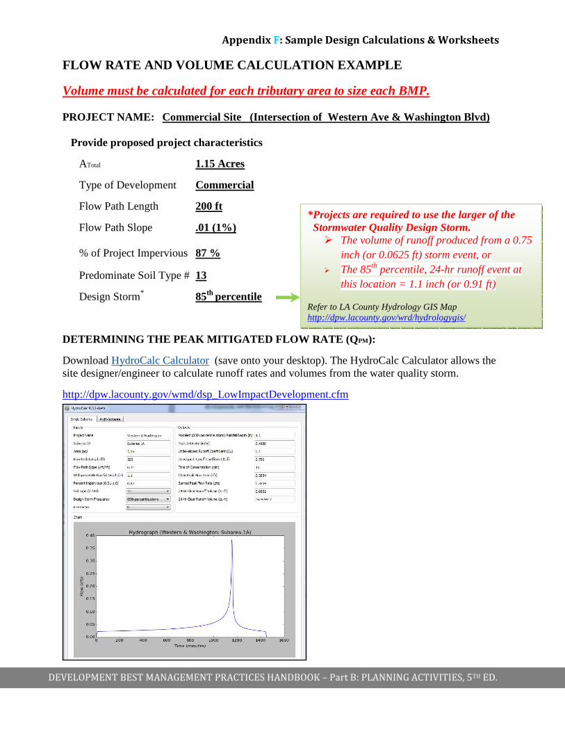
FLOW RATE AND VOLUME CALCULATION EXAMPLE
Volume must be calculated for each tributary area to size each BMP. PROJECT NAME: Commercial Site (Intersection of Western Ave & Washington Blvd)
Provide proposed project characteristics
ATotal 1.15 Acres
Type of Development Commercial
Flow Path Length 200 ft
Flow Path Slope .01 (1%) % of Project Impervious 87 %
Predominate Soil Type # 13
Design Storm* 85th percentile
DETERMINING THE PEAK MITIGATED FLOW RATE (Q PM):
Download HydroCalc Calculator (save onto your desktop). The HydroCalc Calculator allows the site designer/engineer to calculate runoff rates and volumes from the water quality storm.
http://dpw.lacounty.gov/wmd/dsp_LowImpactDevelopment.cfm
*Projects are required to use the larger of the Stormwater Quality Design Storm.
� The volume of runoff produced from a 0.75 inch (or 0.0625 ft) storm event, or
� The 85th percentile, 24-hr runoff event at this location = 1.1 inch (or 0.91 ft)
Refer to LA County Hydrology GIS Map http://dpw.lacounty.gov/wrd/hydrologygis/

Appendix F: Sample Design Calculations & Worksheets
DEVELOPMENT BEST MANAGEMENT PRACTICES HANDBOOK – Part B: PLANNING ACTIVITIES, 5TH ED.
DETERMINING THE VOLUME (V M)
In order to determine the volume (VM) of stormwater runoff to be mitigated from the new development, use the larger storm volume from the following equation(s):
0.75 in Design Storm: VM (ft3) = ( 0.625 Ft ) • Catchment Area (Sq. Ft)
85th Percentile Design Storm: VM (ft3) = (Storm Depth (Ft ) ) • Catchment Area (Sq. Ft)
From Example, 1.1 inch > 0.75 inch, use 1.1 inch (0.91)Design Storm:
A I = 1.0 acres
AP = 0.15 acres VM (ft3) = ( 0.091 ft ) • Catchment Area (in ft
2)
( ) ( )[ ]1.09.0)( 2 •++•= areadundevelopeareaperviousareaimperviousftareaCatchment
( ) ( )[ ][ ]222 4.857,391.015.09.01560,43)( ftacacftftareaCatchment =•+••=
VM (ft3) = ( 0.091 ft ) • 39,857.4 ft2
VM = 3,627 ft3 (verify results with Hydrocalc results)
BMP TYPE AND SIZE 10. List the BMP Type(s) to be used in managing the calculated Vm, and size it per the design criteria listen in Section 4.
The following examples have been provided as a reference:
Infiltration BMPs: • Infiltration Trench • Dry Well • Infiltration Basin
Capture and Use
• Rain Tanks • Above / Below Grade Cisterns
Biofiltration
• Vegetated Swale • Planter Box • Biofiltration with underdrain
Refer to LA County Hydrology GIS Map http://dpw.lacounty.gov/wrd/hydrologygis/
and
http://ladpw.org/wrd/publication/engineering/Final_Report-Probability_Analysis_of_85th_Percentile_24-hr_Rainfall1.pdf

Appendix F: Sample Design Calculations & Worksheets
DEVELOPMENT BEST MANAGEMENT PRACTICES HANDBOOK – Part B: PLANNING ACTIVITIES, 5TH ED.
Infiltration BMP - Design for At Grade Infiltration Trench Givens:
• Vm = 3,627 ft3 (from previous step) • KSat, Measured = 2 in/hr (Do not apply LA County reduction factor) • T = 48 hrs (from Table 4.4) • FS = 3 (from Table 4.4) • Gravel void ratio = 40%
i. Determine KSat, Design
hrinhr
in
FS
KK MeasuredSat
DesignSat 667.03
2,
, ===
ii. Determine Minimum Bottom Infiltration, Amin:
TK
ftinVm
ADesignSat •
•=
,
min
12
2
3
min 359,148/667.0
12627,3ft
hrhrinft
inftA =
•
•=
iii. Determine 3-hr infiltration volume, V3-hr:
32,min3 2263
12
667.0359,13
12fthrs
ftin
hrin
fthrs
ftin
KAV DesignSat
hr =••=•
•=−
iv. Determine the volume stored within the trench, VTrench Storage:
33
067,94.0
627,3ft
ft
ratioVoid
VV m
StorageTrench===
v. Determine remaining volume of storage required:
3333 841,8226067,9 ftftftVVV hrStorageTrenchStorage =−=−= −
vi. Determine Design Depth:
ftft
ft
A
VD Storage
Design 5.6359,1841,8
2
3
min
===

Appendix F: Sample Design Calculations & Worksheets
DEVELOPMENT BEST MANAGEMENT PRACTICES HANDBOOK – Part B: PLANNING ACTIVITIES, 5TH ED.
Infiltration BMP – Design for Below Grade Dry Well
Givens: • Vm = 3,627 ft3 (from previous step) • KSat, Measured = 2 in/hr (Do not apply LA County reduction factor) • Gravel void ratio = 40% • Factor of Safety = 3 (per table 4.4) • Amin = 934 ft2 • D = 6 ft (r = 3 ft)
i. Required dry well depth for the infiltration zone, h:
r
rAh
ππ
2
2min −=
*4884.18
26.28934 22
ftft
ftfth =−=
* Multiple dry wells may be used to achieve the equivalent infiltration zone.
ii. Determine the dry well storage volume, VStorage: (assuming entirely filled with gravel)
RatioVoidVV DryWellWellDryStorage•=
[ ] 4.02 •= hrπ 4.0]48)3([ 2 •••= ftftπ 3543ft=
iii. Determine 3-hr infiltration volume, V3-hr:
32,min3 1563
12
667.09343
12fthrs
ftin
hrin
fthrs
ftin
KAV DesignSat
hr =••=•
•=−
iv. Determine the additional required storage volume, VAdditional Storage:
( ) ( ) 33333 928,2156543627,3 ftftftftVVVV hrWellDrwStoragemStorageAdditional
=+−=+−= −
2,928 ft3 of additional storage is required. In order to satisfy the additional storage requirement, an upstream cistern or additional dry well chambers can be used. Some proprietary systems may provide additional storage capacity. Coordinate with manufactures.

Appendix F: Sample Design Calculations & Worksheets
DEVELOPMENT BEST MANAGEMENT PRACTICES HANDBOOK – Part B: PLANNING ACTIVITIES, 5TH ED.
Infiltration BMP – Design for Below Grade Infiltrat ion Basin
Givens:
• Vm = 3,627 ft3 (from previous step) • KSat, Measured = 2 in/hr (Do not apply LA County reduction factor) • T = 96 hrs (Table 4.4)
i. Determine the design infiltration rate, KSat,Design:
hrinhr
in
FS
KK MeasuredSat
DesignSat 667.03
2,
, ===
ii. Determine Minimum Bottom Infiltration, Amin:
TK
ftinVm
ADesignsat •
•=
,
min
12
2
3
min 68096/667.0
12627,3ft
hrhrinft
inftA =
•
•=
iii. Determine the Basin Design, DBasin:
ftft
ft
A
VD Storage
Ba 3.5680627,3
2
3
minsin ===

Appendix F: Sample Design Calculations & Worksheets
DEVELOPMENT BEST MANAGEMENT PRACTICES HANDBOOK – Part B: PLANNING ACTIVITIES, 5TH ED.
Design for: Capture & Use Givens: • V Design = 3,627 ft3 (from previous step) • 0.15 acres of pervious area • Medium Planting Type → Planting Factor = 0.4
i. Determine the design volume in gallons:
galft
galftgalVDesign 130,2748.7627,3)( 33 =•=
ii. Determine planting area (ft2) within project limits:
22
2 534,6560,4315.0)( ftacftacftAreaPlanting =•=
iii. Determine Planter Factor, PF, (ft2): (Planting factor may vary based on landscape design and plant types. Coordinate with Landscape Architect.)
222 614,2534,64.0)( ftftftFactorPlanter =•=
iv. Determine the 7- month (Oct 1 – April 30) Estimated Total Water Use (ETWU):
PFETETWU month ••=− 62.07)7(
galftETWU month 163,35614,262.07.21 2)7( =••=−
v. Verify ETWU (7-month) is greater than or equal to the VDesigned:
( ) galgalVgalETWU Designmonth 627,3)(163,35)7 =≥=−
∴∴∴∴ CAPTURE & USE IS FEASIABLE

Appendix F: Sample Design Calculations & Worksheets
DEVELOPMENT BEST MANAGEMENT PRACTICES HANDBOOK – Part B: PLANNING ACTIVITIES, 5TH ED.
Biofiltration BMP – Design for Vegetated Swale* Givens: • base of swale = 5 ft • Slope = 3%
i. Determine the swale base width and corresponding unit length:
• Per Table 4.6 → Select swale base of 5 ft with corresponding unit length of 470 ft/ac.
ii. Determine the total swale length:
( )acreftareacatchmentperlenghtSwaleft
acreftareaCatchmentL ftSwale /
560,431
)(5.1 22
)( •
••=
( ) ( )[ ]1.09.0)( 2 •++•= areadundevelopeareaperviousareaimperviousftareaCatchment
( ) ( )[ ][ ]1.0015.09.01560,43)( 22 •++••= ftftareaCatchment
22 4.857,39)( ftftareaCatchment =
acreftft
acreftL ftSwale /470
560,43
14.857,395.1
22
)( •
••=
ftL ftSwale 645)( =
iii. Determine the distance between check dams:
• Per Table 4.7 → At a 3% slope, the distance between check dams is 33 ft.
iv. Determine total number of check dams:
205.1933
645# usedamsofTotal →==
* Depending on the location of the swale, a geotechnical report may need to be submitted and approval from LADBS may be required.
Appendix F: Sample Design Calculations & Worksheets
DEVELOPMENT BEST MANAGEMENT PRACTICES HANDBOOK – Part B: PLANNING ACTIVITIES, 5TH ED.
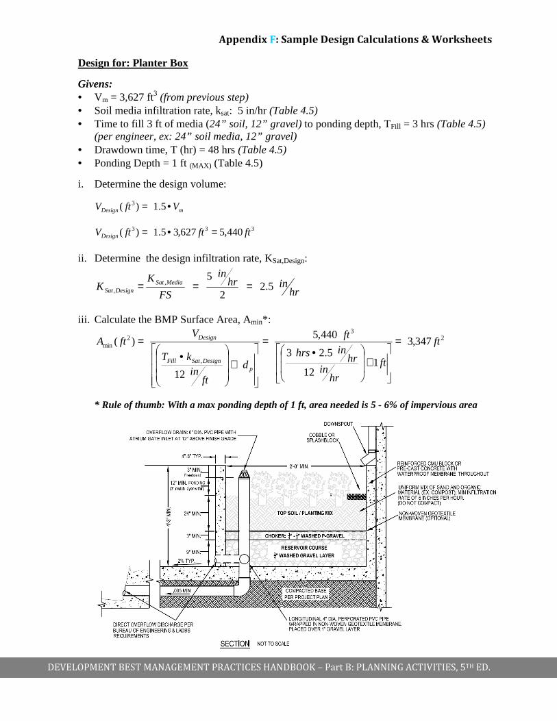
Design for: Planter Box
Givens: • Vm = 3,627 ft3 (from previous step) • Soil media infiltration rate, ksat: 5 in/hr (Table 4.5) • Time to fill 3 ft of media (24” soil, 12” gravel) to ponding depth, TFill = 3 hrs (Table 4.5)
(per engineer, ex: 24” soil media, 12” gravel) • Drawdown time, T (hr) = 48 hrs (Table 4.5) • Ponding Depth = 1 ft (MAX) (Table 4.5)
i. Determine the design volume:
mDesign VftV •= 5.1)( 3
333 440,5627,35.1)( ftftftVDesign =•=
ii. Determine the design infiltration rate, KSat,Design:
hrinhr
in
FS
KK MediaSat
DesignSat 5.22
5,
, ===
iii. Calculate the BMP Surface Area, Amin*:
23
,
2min 347,3
112
5.23
440,5
12
)( ft
ft
hrin
hrinhrs
ft
d
ftin
kT
VftA
pDesignSatFill
Design =
+
•=
+
•=
* Rule of thumb: With a max ponding depth of 1 ft, area needed is 5 - 6% of impervious area

Appendix F: Sample Design Calculations & Worksheets
DEVELOPMENT BEST MANAGEMENT PRACTICES HANDBOOK – Part B: PLANNING ACTIVITIES, 5TH ED.
Alternative Design I
If ponding depth is reduced to 6” (0.50 ft), and the planting media is maintained at 24” and 12” of washed gravel, the minimum planter surface area would then be as follows:
Givens: • Vm = 3,627 ft3 (from previous step) • Soil media infiltration rate, ksat: 5 in/hr (Table 4.5) • Time to fill 3 ft of media (24” soil, 12” gravel) to ponding depth, TFill = 3 hrs (Table 4.5)
(per engineer, ex: 24” soil media, 12” gravel) • Drawdown time, T (hr) = 48 hrs (Table 4.5) • Ponding Depth, dp (ft) = 6” = 0.50ft (Table 4.5)
i. Determine the design volume:
mDesign VftV •= 5.1)( 3
333 440,5627,35.1)( ftftftVDesign =•=
ii. Determine the design infiltration rate, KSat,Design:
hrinhr
in
FS
KK MediaSat
DesignSat 5.22
5,
, ===
iii. Calculate the BMP Surface Area, Amin:
23
,
2min 835,4
50.012
5.23
440,5
12
)( ft
ft
ftin
hrinhr
ft
d
ftin
kT
VftA
pDesignSatFill
Design =
+
•=
+
•=

Appendix F: Sample Design Calculations & Worksheets
DEVELOPMENT BEST MANAGEMENT PRACTICES HANDBOOK – Part B: PLANNING ACTIVITIES, 5TH ED.
Alternative Design II
If ponding depth is reduced to 3” (0.25 ft) and planting media and gravel section total height are proposed to be 24” (2 ft), the minimum planter surface area would then be as follows:
Givens: • Vm = 3,627 ft3 (from previous step) • Soil media infiltration rate, ksat: 5 in/hr (Table 4.5) • Time to fill 2 ft media (18” soil, 6” gravel) to ponding depth, TFill = 2 hrs (Table 4.5)
(per engineer: 18” soil media, 6” gravel) • Drawdown time, T (hr) = 48 hrs (Table 4.5) • Ponding Depth, dp (ft) = 3” (MIN) = 0.25 ft (Table 4.5)
i. Determine the design volume:
333 440,5627,35.1)( ftftftVDesign =•=
ii. Determine the design infiltration rate, KSat,Design:
hrinhr
in
FS
KK MediaSat
DesignSat 5.22
5,
, ===
iii. Calculate the BMP Surface Area, Amin:
23
,
2min 160,8
25.012
5.22
440,5
12
)( ft
ft
ftin
hrinhr
ft
d
ftin
kT
VftA
pDesignSatFill
Design =
+
•=
+
•=
mDesign VftV •= 5.1)( 3
Appendix F: Sample Design Calculations & Worksheets
DEVELOPMENT BEST MANAGEMENT PRACTICES HANDBOOK – Part B: PLANNING ACTIVITIES, 5TH ED.
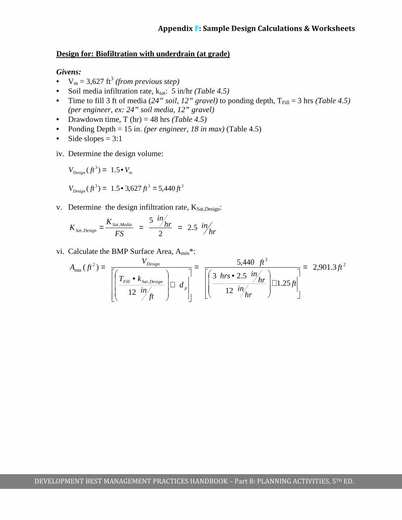
Design for: Biofiltration with underdrain (at grade ) Givens: • Vm = 3,627 ft3 (from previous step) • Soil media infiltration rate, ksat: 5 in/hr (Table 4.5) • Time to fill 3 ft of media (24” soil, 12” gravel) to ponding depth, TFill = 3 hrs (Table 4.5)
(per engineer, ex: 24” soil media, 12” gravel) • Drawdown time, T (hr) = 48 hrs (Table 4.5) • Ponding Depth = 15 in. (per engineer, 18 in max) (Table 4.5) • Side slopes = 3:1
iv. Determine the design volume:
mDesign VftV •= 5.1)( 3
333 440,5627,35.1)( ftftftVDesign =•=
v. Determine the design infiltration rate, KSat,Design:
hrinhr
in
FS
KK MediaSat
DesignSat 5.22
5,
, ===
vi. Calculate the BMP Surface Area, Amin*:
23
,
2min 3.901,2
25.112
5.23
440,5
12
)( ft
ft
hrin
hrinhrs
ft
d
ftin
kT
VftA
pDesignSatFill
Design =
+
•=
+
•=