appendix e—d791 and t791 head and valve holddown … · 34. 1418-2b valve gasket 35. 2439-x...
TRANSCRIPT
19
10
11
2
3
4
5
6
7
8
12
13
15
16
19
18
20
21
23
24
12
17
22
See�gure A
25
13
15
16
17
18
29
23
24
17
25
13
15
16
18
19
26
24
27
16
15
See�gure A
13
12
28
29
30
31
33
34
32
27
28
29
33
34
16
15
13
25
27
16
15
13
25
28
29
35
34
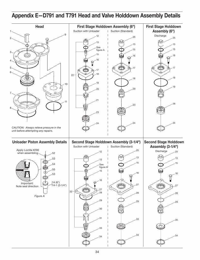
CAUTION: Always relieve pressure in the unit before attempting any repairs.
52
Important:Note seal direction
Apply Loctite #290when assembling
53
54
55
53
14 (6")14-1 (3-1/4")
first stage holddown Assembly (6")
Discharge
first stage holddown Assembly (6") Suction with Unloader Suction (Standard)
second stage holddown Assembly (3-1/4")
Discharge
second stage holddown Assembly (3-1/4") Suction with Unloader Suction (Standard)
unloader piston Assembly details
Figure A
head
Appendix e—d791 and t791 head and valve holddown Assembly details
e. Assembly details
34

36
37
40
3839
42
41
42
37
40
3839
36
41
49
48
47
46
45
44
43
37
51
48
47
46
45
50
43
O-ring CodeA Buna-NB Neoprene®f
D Viton®f
E PTFEK Kalrez®f
ref no. part no. description
1. 3665 Adjusting screw nut2. 2-127 a O-ring3. 3867 Cylinder cap4. 2-250 a O-ring5. 3663 Adjusting cup6. 2-248 a O-ring7. 3876 Cylinder head (6")8. 2-258 O-ring
9. 7001-050-NC150A Bolt (1/2–13x1-1/2" hex hd gr 5)(Torque to 65 ft•lbs)
10. 3877 Cylinder head (3-1/4")11. 2-236 a O-ring12. 2598-1c Unloader cap13. 2-031 a O-ring14. 3696c Unloader piston (6")
14-1. 2618c Unloader piston (3-1/4")15. 2715 Holddown screw
16. 7001-043-NC150A Bolt (7/16–14x1-1/2" hex hd)(Torque to 37 ft•lbs)
17. 1764 Valve cover plate18. 2-235 a O-ring19. 3570-1 Valve cage20. 3694c Actuator21. 3695c Spring22. 3694-X Unloader assembly (6")23. 3732-X Suction valve assembly (6")24. 2114b Valve gasket25. 2714-1 Valve cap26. 3733-X Discharge valve assembly (6")27. 2205 Valve cover plate28. 2-143 a O-ring29. 3569 Valve cage30. 3689c Actuator
ref no. part no. description
31. 3690c Spring32. 3689-X Unloader assembly (3-1/4")33. 2438-X Suction valve assembly (3-1/4")34. 1418-2b Valve gasket35. 2439-X Discharge valve assembly (3-1/4")36. 3827 Valve seat (6")37. 3828 Stud38. 3830d Outer valve plate39. 3831d Inner valve plate40. 3829d Spring41. 3805-X1 Valve repair kit42. 3826 Valve bumper (6")43. 2446 Bolt44. 2438 Suction valve seat (3-1/4")45. 2442 Valve plate46. 2445e Spacer (two per valve)47. 3355 Washer48. 1407 Spring49. 2440 Suction valve bumper (3-1/4")50. 2441 Discharge valve bumper (3-1/4")51. 2439 Discharge valve seat (3-1/4")52. 1910c Bolt53. 2619-Xc Unloader piston seal assembly54. 2857c Unloader piston cap55. 2858c Gasket
a _ denotes O-ring code. See O-ring chart for details.
b Included with valve assembly.c Included with unloader assembly.d Included with valve repair kit.e Install spacers back to back.f Registered trademark of the DuPont company.
first stage valve Assembly (6") Suction Discharge
second stage valve Assembly (3-1/4") Suction Discharge
Appendix e—d791 and t791 head and valve holddown Assembly details
35
1
2
32
3
4
28
Important:Note seal direction
Apply Loctite #290when assembling
29
30
31
29
7
5
15
6
See�gure A
8
9
12
11
13
14
16
17
12
10
18
6
8
9
10
11
19
16
17
10
18
6
8
9
11
12
20
17
21
22
2324
25
26
27
26
22
2324
25
21
27
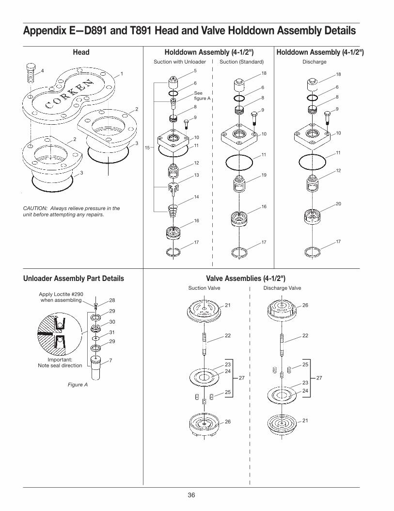
Appendix e—d891 and t891 head and valve holddown Assembly details
head holddown Assembly (4-1/2") Suction with Unloader Suction (Standard)
CAUTION: Always relieve pressure in the unit before attempting any repairs.
valve Assemblies (4-1/2") Suction Valve Discharge Valve
unloader Assembly part details
Figure A
holddown Assembly (4-1/2") Discharge
36
Appendix e—d891 and t891 head and valve holddown Assembly detailsCompressor head and valve bill of materials
ref no.
part no. description
1. 3923 Cylinder cap2. 3924 Cylinder head (4-1/2")3. 2-246 a O-ring
4. 7001-050 NC150ABolt (1/2 - 13 x 1-1/2" hex head Gr 5) (Torque to 65 ft•lbs)
5. 2598-1c Unloader cap6. 2-031 a O-ring7. 3696c Unloader piston8. 2715 Holddown screw
9. 7001-043 NC150ABolt (7/16 - 14 x 1-1/2" hex head)(Torque to 37 ft•lbs)
10. 1764 Valve cover plate11. 2-235 a O-ring12. 3570-1 Valve cage13. 3694c Actuator14. 3695c Spring15. 3694-X Unloader assembly (4-1/2")16. 3732-X Suction valve assembly (4-1/2")17. 2114b Valve gasket
a _ denotes O-ring code. See O-ring chart below for details.b Included with valve assemblyc Included with unloader assemblyd Included with valve repair kit.e Registered trademark of the DuPont company.
ref no.
part no. description
18. 2714-1 Valve cap19. 3569 Valve cage20. 3733-X Discharge valve assembly (4-1/2")21. 3827 Valve seat (4-1/2")22. 3828 Stud23. 3830d Valve plate (outer)24. 3831d Valve plate (inner)25. 3829d Spring26. 3826 Valve bumper (4-1/2")27. 3805-X1 Valve repair kit28. 1910c Bolt29. 2619-Xc Unloader piston seal assembly30. 2857c Unloader piston cap31. 2858c Gasket
O-ring Code
A Buna-N
B Neoprene®e
D Viton®e
E PTFE
K Kalrez®e
37
1
2
3
4
5
4
5
4
5
4
5
6
7
8
9
PistonRod
9
Piston bottom dead center
Piston Piston
(Y) (Y)
Piston top dead center
Piston Piston
(X) (X)
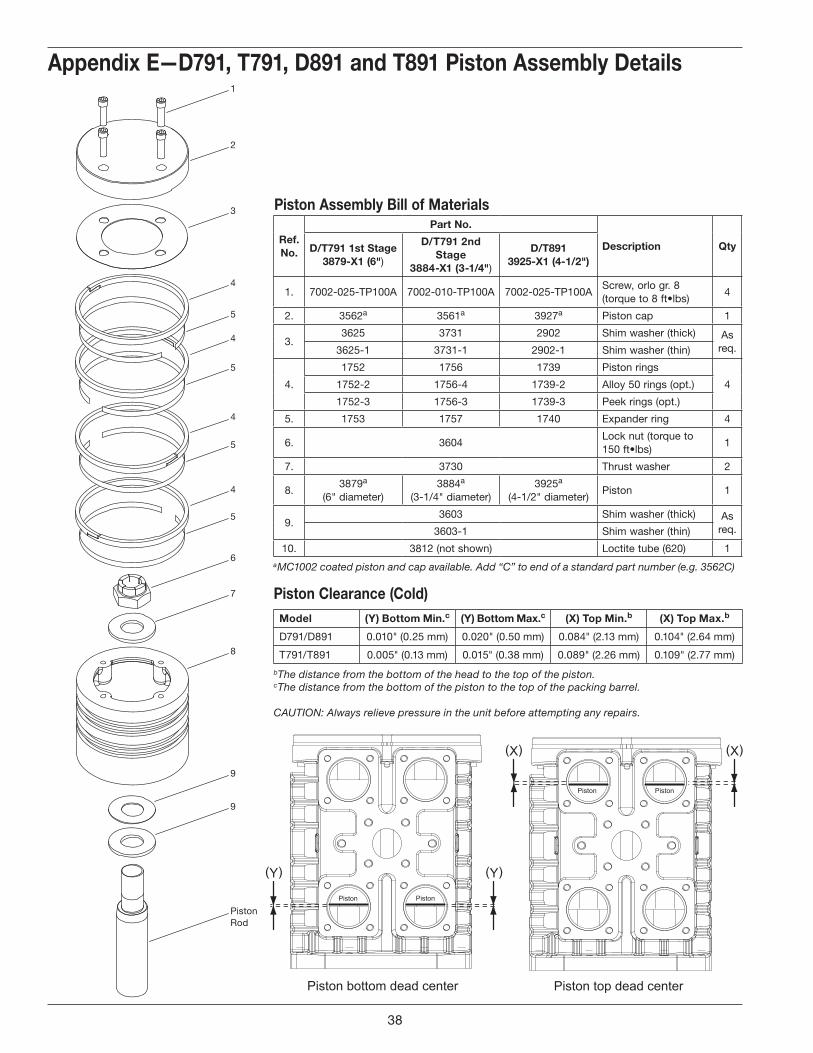
piston Assembly bill of materials
Appendix e—d791, t791, d891 and t891 piston Assembly details
ref. no.
part no.
description Qtyd/t791 1st stage 3879-x1 (6")
d/t791 2nd stage
3884-x1 (3-1/4")
d/t891 3925-x1 (4-1/2")
1. 7002-025-TP100A 7002-010-TP100A 7002-025-TP100AScrew, orlo gr. 8 (torque to 8 ft•lbs)
4
2. 3562a 3561a 3927a Piston cap 1
3.3625 3731 2902 Shim washer (thick) As
req.3625-1 3731-1 2902-1 Shim washer (thin)
4.
1752 1756 1739 Piston rings
41752-2 1756-4 1739-2 Alloy 50 rings (opt.)
1752-3 1756-3 1739-3 Peek rings (opt.)
5. 1753 1757 1740 Expander ring 4
6. 3604Lock nut (torque to 150 ft•lbs)
1
7. 3730 Thrust washer 2
8.3879a
(6" diameter)3884a
(3-1/4" diameter)3925a
(4-1/2" diameter)Piston 1
9.3603 Shim washer (thick) As
req.3603-1 Shim washer (thin)
10. 3812 (not shown) Loctite tube (620) 1
model (Y) bottom min.c (Y) bottom max.c (x) top min.b (x) top max.b
D791/D891 0.010" (0.25 mm) 0.020" (0.50 mm) 0.084" (2.13 mm) 0.104" (2.64 mm)
T791/T891 0.005" (0.13 mm) 0.015" (0.38 mm) 0.089" (2.26 mm) 0.109" (2.77 mm)
piston Clearance (Cold)
b The distance from the bottom of the head to the top of the piston.c The distance from the bottom of the piston to the top of the packing barrel.
CAUTION: Always relieve pressure in the unit before attempting any repairs.
a MC1002 coated piston and cap available. Add “C” to end of a standard part number (e.g. 3562C)
38
1
2
3
7
6
3
8
5
4
Notealignment
marks
5
2
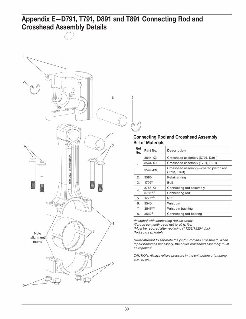
Appendix E—D791, T791, D891 and T891 Connecting Rod and Crosshead Assembly Details
Ref No.
Part No. Description
1.
3544-X3 Crosshead assembly (D791, D891)
3544-X9 Crosshead assembly (T791, T891)
3544-X10Crosshead assembly—coated piston rod (T791, T891)
2. 3590 Retainer ring
3. 1726b Bolt
4.3785-X1 Connecting rod assembly
3785a,d Connecting rod
5. 1727a,b Nut
6. 3540 Wrist pin
7. 3541a,c Wrist pin bushing
8. 3542a Connecting rod bearing
Connecting Rod and Crosshead Assembly Bill of Materials
a Included with connecting rod assemblyb Torque connecting rod nut to 40 ft. lbs. c Must be rebored after replacing (1.1258/1.1254 dia.)d Not sold separately
Never attempt to separate the piston rod and crosshead. When repair becomes necessary, the entire crosshead assembly must be replaced.
CAUTION: Always relieve pressure in the unit before attempting any repairs.
39

1
2
34
5
6
34
5
6
34
5
6
34
5.1
6
7
8
10
11
12
11
13
14
15
11
10
17
16
V-ring Packing Direction
Lower PackingSpecification
“J”
Lower PackingSpecification
“K”
13
14
15
15
14
13
To Crankcase To Crankcase
10
11
12
11
13
14
15
11
10
17
RadialTangent
RadialTangent
RadialTangent
TangentTangent
UpperSegmented
PackingSet
LowerV-ring
PackingSet
LowerV-ring
PackingSet
1
2
34
5
6
34
5
6
34
5
6
34
5.1
6
7
8
16
RadialTangent
RadialTangent
RadialTangent
TangentTangent
UpperSegmented
PackingSet
9 9
Appendix e—d791 and d891 packing Assembly detailsspecification “k”specification “J”
40

V-ringPackingDirection
Lower PackingSpecification
“R”
13
14
15
To Crankcase
16Upper
SegmentedPacking
Set
5.1
1
2
34
6
34
6
34
6
34
5.1
6
9
7
8
5.1
5.1 TangentTangent
TangentTangent
TangentTangent
TangentTangent
10
11
12
11
13
14
15
11
10
17LowerV-ring
PackingSet
packing Assembly bill of materialsref no.
part no. description
1.3886 Packing barrel (3-1/4")(791 second stage)3887 Packing barrel (6")(791 first stage)3926 Packing barrel (4-1/2")(891 only)
2. 3906 Crush gasket
3. 3817Packing cup (Not included in 3810-X1 packing set)
4. 2-036_a,c,d Cup O-ring
5. 3810Segmented packing (radial—tangent) pair
5.1. 3814Segmented packing (tangent—tangent) pair
6. 3811 Back-up ring7. 7002-025OC100A Screw (1/4-20 x 1" socket head)8. 3885 Cartridge9. 1732b Oil deflector ring10. 5000-175 Retainer ring11. 1728 Washer12. 1731 Spring13. 1724 Male packing ring14. 1725 V-ring packing15. 1723 Female packing ring16. 3810-X1d Segmented packing set17. 1725-2X V-ring packing set
identification of packing specification
Example: Model Number D891 K M4FBA Packing Spec.
IMPORTANT: Identify and line up the rings before installing. Be sure they face the way shown here and that the pin and hole are aligned when assembled.
a _ denotes O-ring code. See O-ring chart for details.b Deflector ring is loose within the packing cartridge until fitted on the piston rod. Must be put in from the bottom of the cartridge.
c Starting with S.N. NN51397. d Packing cup O-ring not included in packing set.e Registered trademark of the DuPont company.
Appendix e—d791 and d891 packing Assembly details
To Crankcase
Piston (Pressure) Side
Radial Cut(without pin)
Segmented Packing forSpecification “J” & “K”
Tangent Cut(with pin)
Back-upring
To Crankcase
Piston (Pressure) Side
Tangent Cut(without pin)
Segmented packing forSpecification “J”, “K”, & “R”
Tangent Cut(with pin)
Back-upring
Align pinwith hole
Align pinwith hole
specification “r”
O-ring CodeA Buna-NB Neoprene®e
D Viton®e
E PTFEK Kalrez®e
41

V-ring Packing Direction
Middle PackingSpecification
“G”
Middle PackingSpecification
“H”
13
14
15
15
14
13
To Crankcase To Crankcase
13
14
15
To Crankcase
13
14
15
To Crankcase
Lower PackingSpecification
“G”
Lower PackingSpecification
“H”
RadialTangent
RadialTangent
RadialTangent
TangentTangent
UpperSegmented
PackingSet
11
14
12
15
1620
11
17
11
12
1
2
3
8
18
9
10
13
14
19
15
13
4
56
5
34
5
6
6
76
34
11
10
10
11
LowerV-ring
PackingSet
19MiddleV-ring
PackingSet
UpperSegmented
PackingSet
11
11
15
12
16
14
17
11
12
1
2
3
8
18
9
10
13
1419
15
13
4
56
5
34
5
6
6
76
34
1110
10
11
LowerV-ring
PackingSet
19MiddleV-ring
PackingSet
RadialTangent
RadialTangent
RadialTangent
TangentTangent
34
34
20
PTFE Locking Device PTFE Locking Device
Appendix e—t791 and t891 packing Assembly detailsspecification “h”specification “g”
42

V-ringPackingDirection
Middle PackingSpecification
“F”
13
14
15
To Crankcase
13
14
15
To Crankcase
Lower PackingSpecification
“F”
TangentTangent
TangentTangent
TangentTangent
TangentTangent
UpperSegmented
PackingSet
11
14
12
15
16
11
17
11
12
1
2
3
8
18
9
10
13
14
19
15
13
4
76
7
34
7
6
6
76
34
1110
10
11
LowerV-ring
PackingSet
19MiddleV-ring
PackingSet
PTFE Locking Device
34
20
Appendix e—t791 and t891 packing Assembly detailspacking Assembly bill of materials
ref no.
part no. description
1.3886 Packing barrel (3-1/4")(791 second stage)3887 Packing barrel (6")(791 first stage)3926 Packing barrel (4-1/2")(891 only)
2. 3906 Crush gasket
3. 3817Packing cup (Not included in 3810-X1 packing set)
4. 2-036_a,c,d Cup O-ring
5. 3810Segmented packing (radial—tangent) pair
6. 3811 Back-up ring
7. 3814Segmented packing (tangent—tangent) pair
8. 4748 Packing adapter9. 7002-025OC100A Screw (1/4-20 x 1" socket head)10. 5000-175 Retainer ring11. 1728 Washer12. 1731 Spring13. 1724 Male packing ring14. 1725 V-ring packing15. 1723 Female packing ring16. 4746 Cartridge17. 1722-X Adjusting screw18. 3810-X1d Segmented packing set19. 1725-2X V-ring packing set20. 1732 Oil deflector ring
identification of packing specification
Example: Model Number T891 G L4FBDNSNC Packing Spec.
IMPORTANT: Identify and line up the rings before installing. Be sure they face the way shown here and that the pin and hole are aligned when assembled.
a _ denotes O-ring code. See O-ring chart for details.b Deflector ring is loose within the packing cartridge until fitted on the piston rod. Must be put in from the bottom of the cartridge.
c Starting with S.N. NN51397. d Packing cup O-ring not included in packing set.e Registered trademark of the DuPont company.
To Crankcase
Piston (Pressure) Side
Radial Cut(without pin)
Segmented Packing forSpecification “F” & “G”
Tangent Cut(with pin)
Back-upring
To Crankcase
Piston (Pressure) Side
Tangent Cut(without pin)
Segmented packing forSpecification “F”, “G”, & “H”
Tangent Cut(with pin)
Back-upring
Align pinwith hole
Align pinwith hole
specification “f”
O-ring CodeA Buna-NB Neoprene®e
D Viton®e
E PTFEK Kalrez®e
43

17
17
12
12
13
14
15
16
Packing barrels and cartridges(For parts details, see D791 packing on previous pages).
ref no.
part no. description Qty
1. 3866 Cylinder 1
2. 3442 Pipe plug (1/4" NPT) 10
3. 1054 Drain valve (lubricated models) 1
4. 1071 Nipple (1/4" x close) 1
5. 2-258_a O-ring for cylinder (1st stage) 1
5-1. 2-236_a O-ring for cylinder (2nd stage) 1
6. 7001-050NC175ABolt (1/2" - 13 x 1-3/4" hex head gr 5)
16
7. 3793-2S Flange (inlet/outlet) 4
8. 2-231_a O-ring for flange 4
9. 3253 Roll pin 1
10. 2405-1 Crosshead guide 1
11. 1064 Elbow (1/4" NPT) 1
12. 7005-050175A Bolt (1/2" 13 x 1-3/4" ferry head) 16
13. 1761 Gasket (crankcase) 1
14. 1760 Gasket (inspection cover) 1
15. 1721 Inspection cover 1
16. 7012-010NC025B Bolt (10 - 24 x 1/4" Phillips hd.) 10
17. 2-231_a O-ring 2
Crosshead guide bill of materials
Appendix e—d791 Crosshead guide Assembly details
a _ denotes O-ring code. See O-ring chart above for details.b Registered trademark of the DuPont company.
CAUTION: Always relieve pressure in the unit before attempting any repairs.
NOTE: Packing barrel installation: 1. Use packing installation cone #3905 on the piston rod.2. Insert small barrel first, use finger holes to align slinger ring on to
the rod. Slip the packing barrel into place.3. Align pin with slot in large packing barrel.4. Slip large packing barrel in place.
O-ring Code
A Buna-N
B Neoprene®b
D Viton®b
E PTFE
K Kalrez®b
44

17
17
12
12
13
1415
16
Packing barrels and cartridges(For parts details, see D891 packing on previous pages).
O-ring Code
A Buna-N
B Neoprene®b
D Viton®b
E PTFE
K Kalrez®b
ref no.
part no. description Qty
1. 3922 Cylinder 1
2. 3442 Pipe plug (1/4" NPT) 6
3. 1054 Drain valve (lubricated models) 1
4. 1071 Nipple (1/4" x close) 1
5. 2-246_a O-ring for cylinder 2
6. 7001-050NC175ABolt (1/2"- 13 x 1-3/4" hex head gr 5)
8
7. 3793-2S Flange (inlet/outlet) 2
8. 2-231_a O-ring for flange 2
9. 3253 Roll pin 1
10. 2405-1 Crosshead guide 1
11. 1064 Elbow (1/4" NPT) 1
12. 7005-050175A Bolt (1/2" 13 x 1-3/4" ferry head) 16
13. 1761 Gasket (crankcase) 1
14. 1760 Gasket (inspection cover) 1
15. 1721 Inspection cover 1
16. 7012-010NC025B Screw (10 - 24 x 1/4" Phillips hd.) 10
17. 2-231_a O-ring 2
Crosshead guide bill of materials
Appendix e—d891 Crosshead guide Assembly details
a _ denotes O-ring code. See O-ring chart above for details.b Registered trademark of the DuPont company.
CAUTION: Always relieve pressure in the unit before attempting any repairs.
NOTE: Packing barrel installation: 1. Use packing installation cone #3905 on the piston rod.2. Insert small barrel first, use finger holes to align slinger ring on to
the rod. Slip the packing barrel into place.3. Align pin with slot in large packing barrel.4. Slip large packing barrel in place.
45

18
5-1
1819
19
2020
21
11
11
1213
14
1312
15 1617
21
21 21
2222
Packing barrels and cartridges(For parts details, see T791 packing on previous pages).
ref no.
part no. description Qty
1. 3866 Cylinder 1
2. 3442 Pipe plug (1/4" NPT) 16
3. 1054 Drain valve (lubricated models) 1
4. 1071 Nipple (1/4" x close) 1
5. 2-258_a O-ring for cylinder (1st stage) 1
5-1. 2-236_a O-ring for cylinder (2nd stage) 1
6. 7001-050NC175ABolt (1/2" 13 x 1-3/4" hex head gr 5)
16
7. 3793-2S Flange (inlet/outlet) 4
8. 2-231_a O-ring for flange 4
9. 3253 Roll pin 1
10. 1716-4 Crosshead guide 1
11. 7005-050175A Bolt (1/2" 13 x 1-3/4" ferry head) 16
12. 1748 Cartridge plate 2
13. 5000-350 Retainer ring 2
14. 1761 Gasket (crankcase) 1
15. 1760 Gasket (inspection cover) 1
16. 1721 Inspection cover 1
17. 7012-010NC025B Bolt (10 - 24 x 1/4" Phillips hd.) 10
18. 2-238_a O-ring 2
19. 1749 Cartridge holddown screw 2
20. 4747 Cage 2
21. 2-233_a O-ring 2
22. 1732 Oil deflector ring 2
Crosshead guide bill of materials
Appendix e—t791 Crosshead guide Assembly details
a _ denotes O-ring code. See O-ring chart above for details.b Registered trademark of the DuPont company.
CAUTION: Always relieve pressure in the unit before attempting any repairs.
NOTE: Packing barrel installation: 1. Use packing installation cone #3905 on the piston rod.2. Insert small barrel first, use finger holes to align slinger ring on to
the rod. Slip the packing barrel into place.3. Align pin with slot in large packing barrel.4. Slip large packing barrel in place.
O-ring Code
A Buna-N
B Neoprene®b
D Viton®b
E PTFE
K Kalrez®b
46
18
1819
19
2020
21
11
2
11
1213
14
21
21 21
22
22
1312
15 1617
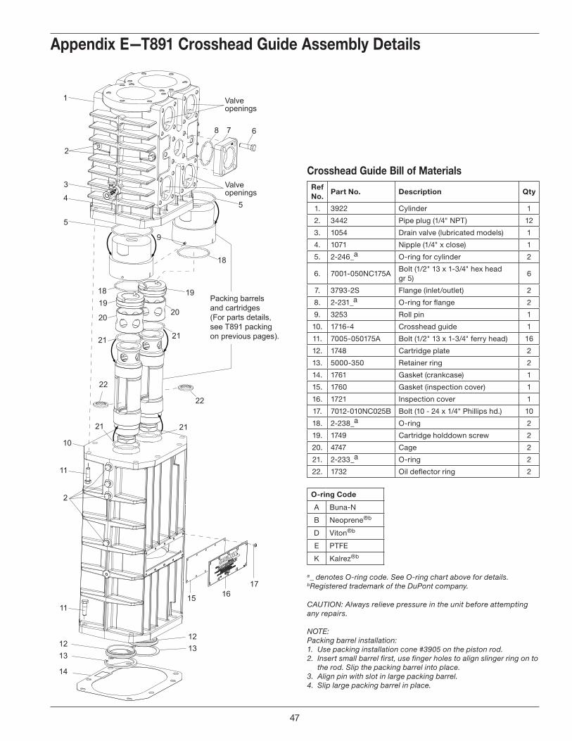
Packing barrels and cartridges(For parts details, see T891 packing on previous pages).
ref no.
part no. description Qty
1. 3922 Cylinder 1
2. 3442 Pipe plug (1/4" NPT) 12
3. 1054 Drain valve (lubricated models) 1
4. 1071 Nipple (1/4" x close) 1
5. 2-246_a O-ring for cylinder 2
6. 7001-050NC175ABolt (1/2" 13 x 1-3/4" hex head gr 5)
6
7. 3793-2S Flange (inlet/outlet) 2
8. 2-231_a O-ring for flange 2
9. 3253 Roll pin 1
10. 1716-4 Crosshead guide 1
11. 7005-050175A Bolt (1/2" 13 x 1-3/4" ferry head) 16
12. 1748 Cartridge plate 2
13. 5000-350 Retainer ring 2
14. 1761 Gasket (crankcase) 1
15. 1760 Gasket (inspection cover) 1
16. 1721 Inspection cover 1
17. 7012-010NC025B Bolt (10 - 24 x 1/4" Phillips hd.) 10
18. 2-238_a O-ring 2
19. 1749 Cartridge holddown screw 2
20. 4747 Cage 2
21. 2-233_a O-ring 2
22. 1732 Oil deflector ring 2
Crosshead guide bill of materials
Appendix e—t891 Crosshead guide Assembly details
a _ denotes O-ring code. See O-ring chart above for details.b Registered trademark of the DuPont company.
CAUTION: Always relieve pressure in the unit before attempting any repairs.
NOTE: Packing barrel installation: 1. Use packing installation cone #3905 on the piston rod.2. Insert small barrel first, use finger holes to align slinger ring on to
the rod. Slip the packing barrel into place.3. Align pin with slot in large packing barrel.4. Slip large packing barrel in place.
O-ring Code
A Buna-N
B Neoprene®b
D Viton®b
E PTFE
K Kalrez®b
47

12
34
5
6
710
4
30
54
2931
52
53
27
63 (Pipe plug on under side ofcrankcase is not shown)
8
21
17
16
3738
394140
15
54
14
1819
20
22232425
26
9
11
12
135
33
34
35
43
4445
46
4748
42
51
4956
50
3632
59
5533
606242
28
55
61(Includes all parts shown
except #52 and #53)
50
58
Inside ofBearing Carrier
Pump Cover Oil/Filter Adapter
Oil Passage HoleImportant! Line up hole in
gasket with oil passage hole.
Pumpside of adapter shown forproper orientation of cover and
location of pump cover pin.
57
55
60
28
Appendix e—Crankcase Assembly details
48

Appendix e—Crankcase Assembly details
ref no. part no. description
1. 1737 Bearing cone
2. 3638 Spacer
3. 3635 Drive sprocket
4. 1284 Crankshaft orifice
5. 2135 Drive pin
6. 2933 Link pin
7. 3786 Crankshaft
8. 3503 Flywheel key
9. 3580 Bearing cone
10. 3786-X1 Crankshaft assembly
11. 7001-031NC075A Bolt (5/16 - 18 x 3/4" hex head)
12. 2122 Inspection cover
13. 2123 Gasket, inspection cover
14. 2-112_c O-ring
15. 3225-X1 Oil bayonet assembly (w/O-ring)
16. 2126 Breather ball
17. 3579 Bearing cup
18.
3589 Bearing adjustment shim (.005")
3589-1 Bearing adjustment shim (.007")
3589-2 Bearing adjustment shim (.020")
19. 3539 Bearing cover
20. 3526 Oil seal
21. 1280 Filter screw
22. 1281 Gasket, filter
23. 2-116_c O-ring
24. 1276 Washer
25. 1275 Oil filter screen
26. 3443 Pipe plug (1/2" NPT steel)
27. 3221 Crankcase
28. 7001-037NC100A Bolt (3/8 - 16 x 1" hex head Gr. 5)
29. 3875 Access cover
30. 7003-025NC037E Screw (1/4 - 20 x 3/8")
31. 3874 Gasket (access cover)
32. 1515-X Closure cap assembly
33. 7001-025NC050A Bolt (1/4 - 20 x 1/2" hex head)
34. 1515 Closure cap
35. 1516 Closure body
36. 2-118_c O-ring
37. 1290 Relief valve adjusting screw
38. 2-011_c O-ring
39. 1291 Adjusting screw locknut
40. 1292 Relief valve spring
41. 1293 Relief valve ball
42. 4222-Xb Oil filter adapter assembly (w/pin)
43. 2-228_c O-ring
44. 2849-1Xb Oil pump assembly
45. 2851 Spring guide
46. 2852 Oil pump spring
Crankcase Assembly bill of materials
Assembly number Assembly name
3221-X1 Crankcase assembly (M, 4, 8, 9) without lubricator
3221-X2 Crankcase assembly (M7, 78) without lubricator
3221-X3 Crankcase assembly (L, 4, 8, 9) with lubricator
3221-X4 Crankcase assembly (L7, 78) with lubricator
a Must be rebored and honed after replacing (0.876"/0.875" diameter)b Caution: To avoid damage during assembly, refer to installation Instruction Manual IE400.
c _ denotes O-ring code. See O-ring chart above for details.d Registered trademark of the DuPont company. CAUTION: Always relieve pressure in the unit before attempting any repairs.
ref no. part no. description
47. 3219 Pump shaft adapter
48. 2-112_c O-ring
49. 2805-Xa Pump shaft bushing
50. 1629 Pipe plug (1/16 NPT fl. seal)
51. 1736 Bearing cup
52. 1302 Oil pressure gauge
53. 1044 Bushing (1/8 x 1/4 NPT)
54. 3220-2 Bearing carrier
55. 3289 Pipe plug (1/4 NPT fl. seal)
56. 2131 Bearing carrier gasket
57. 2961-X Air release valve assembly
58. 2590 Pipe plug (1/8 NPT fl. seal)
59. 4225 Filter
60. 2798 Pump cover pin (included w/4222-X)
61. 3220-2X Bearing carrier assembly
62. 4222 Oil filter adapter
63. 3289 Pipe plug (1/4" x 18 NPTF x 7/8")
O-ring Code
A Buna-N
B Neoprene®b
D Viton®b
E PTFE
K Kalrez®b
49

Back Side Front Side
Assembly Number Assembly Name
3852-X Flywheel assembly (flywheel, hub, and three bolts)
3852 Flywheel: 21.2" O.D., 5 groove
H J-2.125 Hub with three bolts and lockwashers
flywheel Assembly bill of materials
Appendix e—flywheel Assembly details
50