appendix e fct document cover sheet - us … · appendix e fct document cover sheet...
TRANSCRIPT
Page E-1 FCRD-TIO-2011-000050, Rev. 0
FCT Quality Assurance Program Document
Appendix E FCT Document Cover Sheet
(Name/Signature) (Date) *Note: In some cases there may be a milestone where an item is being fabricated, maintenance is being performed on a facility, or a document is being issued through a formal document control process where it specifically calls out a formal review of the document. In these cases, documentation (e.g., inspection report, maintenance request, work planning package documentation, or the documented review of the issued document through the document control process) of the completion of the activity along with the Document Cover Sheet is sufficient to demonstrate achieving the milestone. QRL for such milestones may also be marked N/A in the work package provided the work package clearly specifies the requirement to use the Document Cover Sheet and provide supporting documentation.
Name/Title of Deliverable/Milestone Hydride Rim Formation in Unirradiated Zircaloy Work Package Title and Number FT-13PN080505 – ST Storage and Transportation Experiments - PNNL Work Package WBS Number 1.02.08.22 Milestone Number M2FT-13PN0805051
Responsible Work Package Manager
Brady Hanson 30-Apr-2013 (Name/Signature) (Date Submitted)
Quality Rigor Level for Deliverable/Milestone
QRL-3 QRL-2 QRL-1 Nuclear Data
N/A*
This deliverable was prepared in accordance with Pacific Northwest National Laboratory (Participant/National Laboratory Name) QA program which meets the requirements of
DOE Order 414.1 NQA-1-2000 Other: This Deliverable was subjected to:
Technical Review Peer Review
Technical Review (TR) Peer Review (PR) Review Documentation Provided Review Documentation Provided
Signed TR Report, or Signed PR Report, or TR Report No.: PR Report No.:
Signed TR Concurrence Sheet (attached), or Signed PR Concurrence Sheet (attached), or Signature of TR Reviewer(s) below Signature of PR Reviewers below
Name and Signature of Reviewers Carl Beyer 4/29/2013
USED FUEL DISPOSITION CAMPAIGN
Hydride Rim Formation in Unirradiated Zircaloy
Prepared for U.S. Department of Energy
Used Fuel Disposition Campaign
Brady Hanson
Rick Shimskey Curt Lavender
Paul MacFarlan Paul Eslinger
April 30, 2013
FCRD-USED-2013-000151
PNNL-22438

USED FUEL DISPOSITION CAMPAIGN Hydride Rim Formation in Unirradiated Zircaloy
ii April 30, 2013
Disclaimer
This information was prepared as an account of work sponsored by an agency of the U.S. Government. Neither the U.S. Government nor any agency thereof, nor any of their employees, makes any warranty, expressed or implied, or assumes any legal liability or responsibility for the accuracy, completeness, or usefulness, of any information, apparatus, product, or process disclosed or represents that its use would not infringe privately owned rights. References herein to any specific commercial product, process, or service by trade name, trade mark, manufacturer, or otherwise, does not necessarily constitute or imply its endorsement, recommendation, or favoring by the U.S. Government or any agency thereof. The views and opinions of the authors expressed herein do not necessarily state or reflect those of the U.S. Government or any agency thereof.

USED FUEL DISPOSITION CAMPAIGN Hydride Rim Formation in Unirradiated Zircaloy April 30, 2013 iii
Peer Review: Signature on File __________________________________________ Carl E. Beyer Pacific Northwest National Laboratory Concurrence:
__________________________________________ Ken B. Sorenson (Sandia National Laboratories) Storage and Transportation Control Account Manager Submitted by:
Signature on File __________________________________________ Brady D. Hanson Lab Lead ST Experiments

USED FUEL DISPOSITION CAMPAIGN Hydride Rim Formation in Unirradiated Zircaloy
iv April 30, 2013

USED FUEL DISPOSITION CAMPAIGN Hydride Rim Formation in Unirradiated Zircaloy April 30, 2013 v
EXECUTIVE SUMMARY
This report fulfills the M2 milestone M2FT-13PN0805051, “Data Report on Hydrogen Doping/Distribution Tests,” under Work Package Number FT-13PN080505.
The purpose of this work is to develop the means of pre-hydriding unirradiated Zircaloy cladding such that a high concentration, or rim, of hydrides is formed at the cladding outside diameter as is found in cladding for high burnup fuels. Samples prepared by this method will then be used in separate effects tests to determine the effect of hydrides and hydride reorientation on mechanical properties of cladding. Specifically, it is necessary to determine the contribution the lack of hydride rim in the pre-hydrided samples tested by Billone et al. (2008, 2013) had on the ductile-to-brittle transition temperature when compared to irradiated cladding. Results of these tests will also help inform the models being developed for hydride behavior by identifying those parameters of importance.
The initial work performed at Pacific Northwest National Laboratory demonstrated that:
it is possible to pre-hydride samples at low temperatures (<400°C) in pure H2
it appears possible to form the desired hydride rim using this technique
surface conditions of the cladding, and especially the presence or growth of an oxide layer during hydrogen loading, are controlling factors in this process
hydrogen/hydride redistribution is not as well understood as has been reported in literature.
Work will continue and will examine:
Kinetics and effects of variable H2 gas compositions (i.e., < 100%)
Better control of gas impurities such as oxygen or water vapor either through
- Installation of getters on the gas lines or
- Wrapping samples in high purity Al foil to getter oxygen, as is done by Billone (Billone et al. 2013)
Better control of clad surface conditions either through
- More controlled surface blasting or
- Treatment in HF to thoroughly remove the oxide layer
Better control of important parameters such as local temperature, gas flow rate, and sample cooling rate
Testing of cladding alloys other than just Zircaloy-4 to determine the effect of chemical composition as well as texture on the ability to form the hydride rim
Hydrogen redistribution at the longer times suggested by the model of Sawatzky (Sawatzky 1960).


USED FUEL DISPOSITION CAMPAIGN Hydride Rim Formation in Unirradiated Zircaloy April 30, 2013 vii
ACKNOWLEDGMENTS
The authors thank Monty Telander, Monty Elmore, Mike Dahl, and Karl Mattlin for their assistance with experimental setup and operations.
We thank Colleen Winters and Susan Tackett, scientific and technical communications specialists, for editing assistance.

USED FUEL DISPOSITION CAMPAIGN Hydride Rim Formation in Unirradiated Zircaloy
viii April 30, 2013
CONTENTS
EXECUTIVE SUMMARY .......................................................................................................................... v
ACKNOWLEDGMENTS .......................................................................................................................... vii
ACRONYMS ............................................................................................................................................. xiii
1. INTRODUCTION .............................................................................................................................. 1
2. BACKGROUND ................................................................................................................................ 3
2.1 Cladding Manufacture .............................................................................................................. 6
2.2 Hydrogen Uptake ................................................................................................................... 13
2.3 Hydrogen Redistribution ........................................................................................................ 14
3. EXPERIMENTAL SETUP .............................................................................................................. 17
3.1 Hydrogen Loading Tests ........................................................................................................ 17
3.2 Hydride Redistribution Tests ................................................................................................. 19
3.3 Post-test Examinations ........................................................................................................... 21
4. RESULTS ......................................................................................................................................... 25
4.1 Hydrogen Loading Tests ........................................................................................................ 25 4.1.1 Initial Low Temperature Hydriding .......................................................................... 25 4.1.2 TI-1: Confirm 300°C Results with Elevated Temperature Heat Soak and
Controlled Cooling in Argon .................................................................................... 28 4.1.3 TI-2: Repeat of Test TI-1 without Elevated Heat Soak ........................................... 31 4.1.4 TI-3: Varying of Surface Finish of Cladding ........................................................... 34 4.1.5 TI-4: Effects on Performing Multiple Cycles on Hydrogen Adsorption .................. 39
4.2 Hydride Redistribution Tests ................................................................................................. 41 4.2.1 Convection Furnace Method ..................................................................................... 41 4.2.2 Autoclave Method ..................................................................................................... 43
5. LESSONS LEARNED AND FUTURE WORK .............................................................................. 47
6. REFERENCES ................................................................................................................................. 49
USED FUEL DISPOSITION CAMPAIGN Hydride Rim Formation in Unirradiated Zircaloy April 30, 2013 ix
FIGURES
Figure 2.1. The compacted sponge (a) is assembled, by welding, to produce the first melt electrode (b). .................................................................................................................... 6
Figure 2.2. The first melt electrode is consolidated by melting in a VAR (a) and re-melted once or twice to produce larger ingots (b). .......................................................... 7
Figure 2.3. Typical forged log from a VAR ingot. ........................................................................ 7
Figure 2.4. Extrusion billets (a) machined for extrusion to seamless tubes (b). ............................ 8
Figure 2.5. Pilger mill and tooling used to cold reduce extrusions to final hollow (a). On a periodic basis the pilgered tubes are vacuum annealed to restore formability (b). .................................................................................................................................... 8
Figure 2.6. Examples of final pilger reductions and mills used for commercial fuel cladding production. ........................................................................................................ 9
Figure 2.7. Example pilger dies showing the wide variation in design used in commercial zirconium cladding tube production. ............................................................................. 10
Figure 2.8. Typical recovery curves for zirconium based alloys. ................................................ 11
Figure 2.9. Illustration of two reductions used to produce the same tube (bottom) where the one on the left produces a radial texture and the one on the right produces a circumferential texture. .................................................................................................. 11
Figure 2.10. The tube on the left (a) was produced using a high Q reduction and resulted in the desirable circumferential orientation of hydride, as shown by the dark lines in the white zirconium matrix. The tube on the right (b) is an example of what the hydrides would look like if a tube were produced with a very low Q final reduction. ............................................................................................................... 12
Figure 3.1. Tube furnace for pre-hydriding unirradiated Zircaloy. ............................................. 18
Figure 3.2. CAMCo Hydrogen/Inert gas furnace. ....................................................................... 19
Figure 3.3. Cooling block method. .............................................................................................. 20
Figure 3.4. Autoclave method. ..................................................................................................... 20
Figure 3.5. Metallographic sample saw and radial cut specimen. ............................................... 21
Figure 3.6. LECO Series 400 inert gas fusion analyzer. .............................................................. 22
USED FUEL DISPOSITION CAMPAIGN Hydride Rim Formation in Unirradiated Zircaloy
x April 30, 2013
Figure 3.7. Metallographic polishing equipment used. ................................................................ 23
Figure 3.8. Metallographic images of hydrided Zircaloy (a) polished with SiC 400-1200 grit paper and (b) followed by a 0.5 wt% HF – 30 wt% HNO3 etch while polishing with cotton swab and rinsed in DI water. ....................................................... 23
Figure 4.1. Comparison of hydrogen uptake in 100% hydrogen after 24 hours as function of temperature. ............................................................................................................... 27
Figure 4.2. Metallographic images of 275°C sample after 24 hours. .......................................... 28
Figure 4.3. Metallographic images of 300°C sample after 24 hours. .......................................... 28
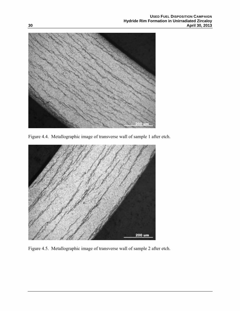
Figure 4.4. Metallographic image of transverse wall of sample 1 after etch. .............................. 30
Figure 4.5. Metallographic image of transverse wall of sample 2 after etch. .............................. 30
Figure 4.6. Metallographic image of transverse wall of sample 4 after etch. .............................. 32
Figure 4.7. Metallographic image of transverse wall of sample 5 after etch. .............................. 32
Figure 4.8. Metallographic image of transverse wall of sample 6 after etch. .............................. 33
Figure 4.9. Significant hydride formation near surface defect on OD. ........................................ 33
Figure 4.10. Blasted OD/chemical etched ID condition for sample 7. ........................................ 36
Figure 4.11. Chemical etched OD and ID for sample 7. .............................................................. 36
Figure 4.12. As-received finish: belt ground OD/etched ID for sample 7. ................................. 37
Figure 4.13. Blasted OD/Chemical etched ID condition for sample 8. ....................................... 37
Figure 4.14. Chemical etched OD and ID for sample 8. .............................................................. 38
Figure 4.15. As-received finish: belt ground OD/etched ID for sample 8. ................................. 38
Figure 4.16. Sample 9 after one 8 hour cycle at 300°C in 100% hydrogen. ............................... 40
Figure 4.17. Sample 9 after two 8 hour cycles at 300°C in 100% hydrogen. .............................. 41
Figure 4.18. Metallographic images of the traverse section of pre-loaded samples containing ~400 ppm hydrogen. .................................................................................... 42
Figure 4.19. Metallographic examination of sample post thermal treatment. ............................. 43

USED FUEL DISPOSITION CAMPAIGN Hydride Rim Formation in Unirradiated Zircaloy April 30, 2013 xi
Figure 4.20. Metallographic image of transverse section of middle of sample tube from second autoclave test (200 hours). ................................................................................. 44
Figure 4.21. Metallographic image of transverse section of the end of sample tube near the Swagelok seal from second autoclave test (200 hours). .......................................... 45
TABLES
Table 2.1. Nominal compositions of Zirconium based nuclear fuel clad alloys. ........................... 4
Table 2.2. Hydrogen diffusion distances in Zr-4 in 1 hour. ......................................................... 15
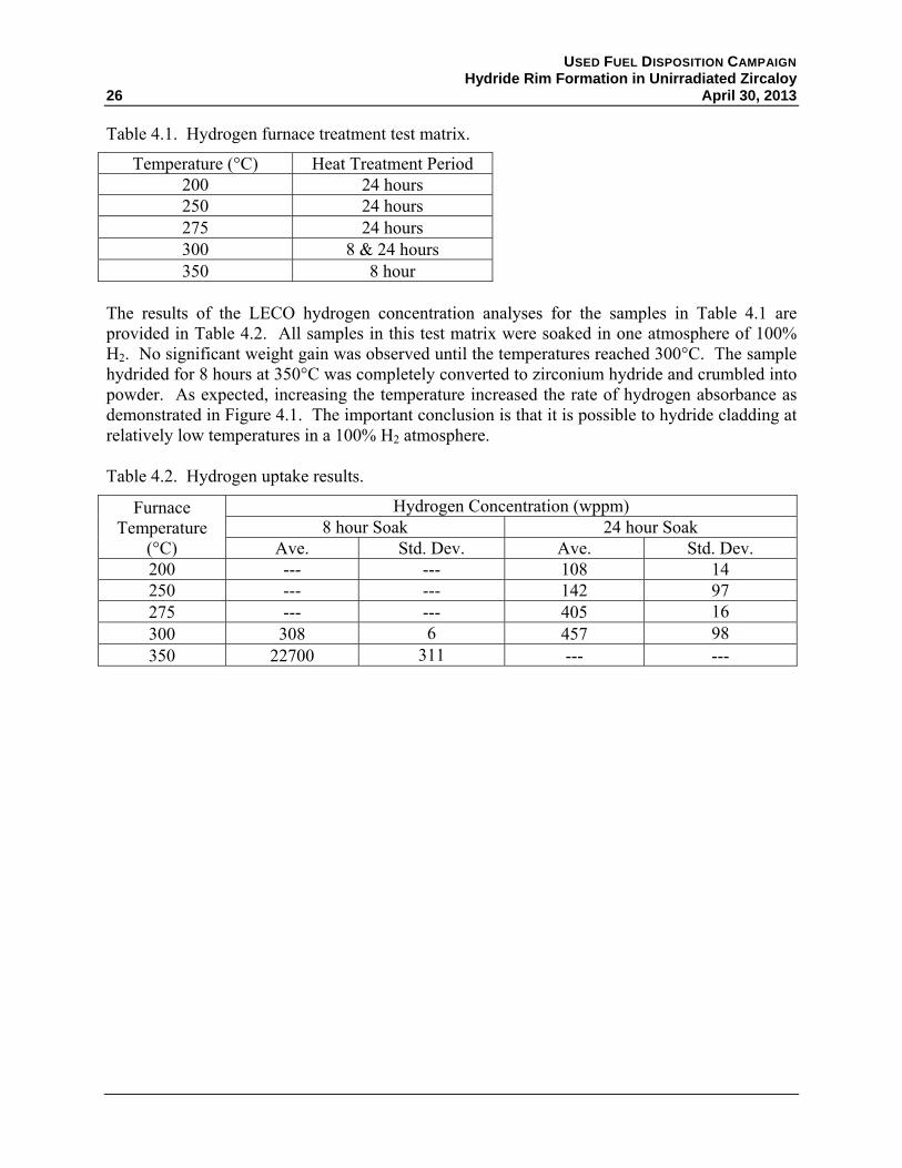
Table 4.1. Hydrogen furnace treatment test matrix. .................................................................... 26
Table 4.2. Hydrogen uptake results. ............................................................................................ 26
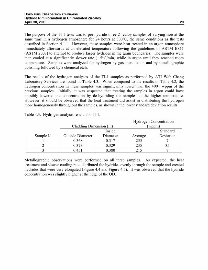
Table 4.3. Hydrogen analysis results for TI-1. ............................................................................ 29
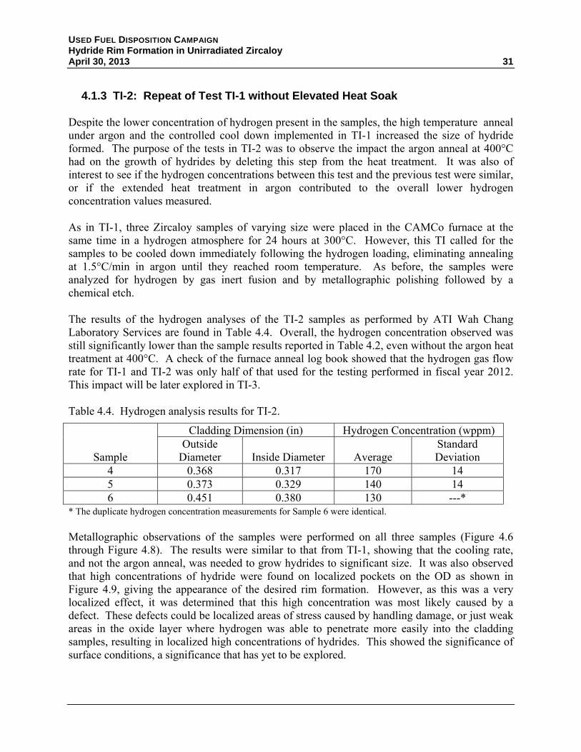
Table 4.4. Hydrogen analysis results for TI-2. ............................................................................ 31
Table 4.5. Hydrogen analysis results for TI-3. ............................................................................ 35
Table 4.6. Hydrogen analysis results for TI-4. ............................................................................ 39


USED FUEL DISPOSITION CAMPAIGN Hydride Rim Formation in Unirradiated Zircaloy April 30, 2013 xiii
ACRONYMS
ASTM ASTM International BWR boiling water reactor CFR Code of Federal Regulations CWSR cold work stress relief anneal DI deionized HF hydrogen flouride ID inside diameter NRC U.S. Nuclear Regulatory Commission NUREG publication prepared by staff of the U.S. Nuclear Regulatory Commission OD outside diameter PH pre-hydrided (cladding) PNNL Pacific Northwest National Laboratory PWR pressurized water reactor PRXA partial recrystallization anneal RXA full recrystallization anneal SiC silicon carbide TI test instruction UFDC Used Fuel Disposition Campaign UNF used nuclear fuel U.S. United States (adjective) VAR vacuum arc remelt (furnace) wppm parts per million by weight Zr-2 Zircaloy-2 Zr-4 Zircaloy-4


USED FUEL DISPOSITION CAMPAIGN Hydride Rim Formation in Unirradiated Zircaloy April 30, 2013 1
USED FUEL DISPOSITION CAMPAIGN Hydride Rim Formation in Unirradiated Zircaloy
1. INTRODUCTION
The U.S. Department of Energy Office of Nuclear Energy, Office of Fuel Cycle Technology has established the Used Fuel Disposition Campaign (UFDC) to conduct the research and development activities related to storage, transportation, and disposal of used nuclear fuel (UNF) and high-level radioactive waste. Within the UFDC, the storage and transportation task has been created to address issues of extended or long-term storage and transportation. The near-term objectives of the storage and transportation task are to use a science-based, engineering-driven approach to
develop the technical bases to support the continued safe and secure storage of UNF for extended periods
develop the technical bases for retrieval of UNF after extended storage
develop the technical bases for transport of high burnup fuel, as well as low and high burnup fuel after dry storage.
Current regulations of the U.S. Nuclear Regulatory Commission (NRC) require (10 CFR 72.122(h)) that “spent fuel cladding must be protected during storage against degradation that leads to gross ruptures or the fuel must be otherwise confined such that degradation of the fuel during storage will not pose operational safety problems with respect to its removal from storage.” Gross ruptures or breaches are defined in NUREG-1536 (NRC 2010) as any cladding breach greater than 1 mm. Thus, even though NRC does not explicitly consider cladding as a confinement barrier, as evidenced by failed fuel assemblies being allowed into dry cask storage systems as long as they are in a damaged fuel can, the state and material properties of the cladding currently are still important to licensing.
For the purposes of the UFDC program, retrievability and operational safety concerns also apply to the fuel after transportation so that, if necessary, the fuel can be transloaded into waste packages for disposal or handled in a reprocessing facility. In January 2013, NRC formally solicited public comment (Federal Register, Volume 78, Issue 12) for potential rulemaking changes that could affect retrievability, cladding integrity, and safe handling of spent fuel. The UFDC continues to pursue alternatives to individual fuel assembly retrievability (e.g., canning individual or small numbers of assemblies or direct disposal of canisters). Such alternatives may facilitate the demonstration of subcriticality in the case of cladding damage and fuel relocation or minimize the need to maintain cladding integrity. However, until regulations change and it can be demonstrated that for future waste management needs it is no longer necessary, fuel assembly retrievability remains a key feature for the UFDC.
The Gap Analysis to Support Extended Storage of Used Nuclear Fuel (Hanson et al. 2012a, also known as the UFDC Gap Analysis) was prepared to document the methodology for determining

USED FUEL DISPOSITION CAMPAIGN Hydride Rim Formation in Unirradiated Zircaloy
2 April 30, 2013
the data gaps and to assign an initial priority (Low, Medium, High) of importance for additional research and development to close the data gaps. The analysis was based on normal conditions of extended storage and informed by subsequent transportation needs. An update of the UFDC Gap Analysis report is planned for fiscal year 2013 to fully evaluate data gaps associated with transportation as well as design-basis phenomena (e.g., design-basis seismic events) and specific accident conditions (e.g., cask tipover). UFDC performed a second, more quantitative prioritization of the research to address the High and Medium priority gaps in the draft report Used Nuclear Fuel Storage and Transportation Data Gap Prioritization (Hanson et al. 2012b, also known as the UFDC Gap Prioritization). This prioritization report also considered anticipated high- and medium priority gaps associated with transportation and the design-basis phenomena and accident conditions during extended storage.
One of the gaps identified as a high priority is Hydrogen Effects: Embrittlement and Reorientation. The work of Billone et al. (2008, 2013) in support of NRC and the UFDC has shown that at high temperatures and stress, the normally circumferential hydrides found in high burnup (i.e., >45 gigawatt-days per metric ton uranium) cladding can reorient in the radial direction and result in brittle mechanical properties. Cladding that has cooled below this ductile-to-brittle transition temperature may be susceptible to breach when subjected to outside stresses such as during handling or normal conditions of transport.
Billone et al. (2013) compared the results of ring compression tests on unirradiated, pre-hydrided (PH) cladding with the cladding of high burnup fuel. They found that the PH samples had significantly higher ductility than the high burnup cladding. Two significant differences exist between the PH and high burnup cladding: 1) the PH cladding had a relatively uniform distribution of hydrides across the cladding radius whereas the high burnup cladding of approximately equal total hydrogen content exhibited a non-uniform distribution across the radius with a high concentration of hydrides at the outer diameter (i.e., a rim) and 2) the PH cladding had no irradiation damage whereas the radiation damage in high burnup cladding is known to significantly decrease ductility and increase hardness.
Multiple laboratories within the UFDC are performing separate effects tests to determine the role various parameters (hydride content and distribution, radiation damage, oxide thickness, etc.) play in determining the mechanical properties of irradiated cladding and how they change over time in extended storage. Billone et al. (2013) concluded that the difference in hydride distribution between PH and irradiated cladding was significant. Separate effects tests at Pacific Northwest National Laboratory (PNNL) were initiated to develop a means for pre-hydriding cladding such that the concentration, distribution, and morphology are the same as in high burnup cladding.
This report outlines the factors that are important in the initial hydriding of unirradiated cladding and how the manufacturing steps of Zircaloy cladding influence the hydride behavior. A brief review of hydrogen uptake and redistribution is presented. The results of the initial attempts at forming the hydride rim are shown and recommendations for future work given. Note that while reorientation of the hydrides (from circumferential to radial) is ultimately the goal of this work, the factors that affect reorientation will be examined later after the procedure for pre-hydriding cladding is established.

USED FUEL DISPOSITION CAMPAIGN Hydride Rim Formation in Unirradiated Zircaloy April 30, 2013 3
2. BACKGROUND
Alloys of zirconium (i.e., Zircaloy) have been used as cladding for nuclear fuel because of its low thermal neutron absorption cross section and their relatively good corrosion resistance and resistance to radiation damage. The typical alloying elements are tin (Sn), iron (Fe), chromium (Cr), niobium (Nb), nickel (Ni), and oxygen (O). The elements Sn and O are interstitial strengtheners whereas Fe, Cr, Ni and Nb tend to form intermetallics and are found as discrete second phases in the zirconium (Zr) matrix. The alloying elements and composition are varied to provide the proper corrosion resistance while maintaining strength and ductility to prevent failures during reactor operations.
For example, it was discovered that the presence of Ni in Zircaloy-2 (Zr-2) promoted absorption of hydrogen. Since Pressurized Water Reactors (PWRs) use an overpressure of hydrogen in the reactor coolant, Zircaloy-4 (Zr-4) was developed where the Ni was replaced with additional Fe to maintain corrosion resistance. Thus, most cladding in Boiling Water Reactors (BWRs) is Zr-2 whereas PWRs have used Zr-4. Recently, newer alloys such as ZIRLO™ and M5® have been developed to further reduce corrosion as the trend is to go to higher burnups and thus longer residence time of the fuel in the reactor core. These newer alloys use Nb to improve corrosion resistance. The common Zircaloy alloys used for commercial fuel cladding production are given in Table 2.1.

USED FUEL DISPOSITION CAMPAIGN Hydride Rim Formation in Unirradiated Zircaloy
4 April 30, 2013
Allo
yS
n (
wt%
)F
e (w
t%)
Cr
(wt%
)N
b (w
t%)
Ni (
wt%
)O
(w
t%)
C (
wt%
)S
i (w
t%)
Zr
(wt%
)
Zr-
2 (
BW
R)
1.5
0.12
0.1
0.05
0.13
Bal
ance
Zr-
2 (
BW
R)
Impr
oved
1.3
0.17
0.1
0.06
0.13
Bal
ance
Zr
-4 (
PW
R)
Hig
h T
in1.
550.
220.
120.
120.
015
0.01
Bal
ance
Zr
-4 (
PW
R)
Im
prov
ed1.
30.
220.
120.
120.
012
0.01
Bal
ance
M5
®0.
041
0.14
Bal
ance
ZIR
LO™
10.
11
0.12
Bal
ance
Opt
imiz
ed
ZIR
LO ™
0.7
0.1
10.
12B
alan
ce
UN
S R
6090
1 (Z
r 2.
5Nb)
A
TS
M B
353
2.6
0.13
Bal
ance
Zirc
alo
y 2
Spe
cific
atio
n A
ST
M B
811
1.2
- 1
.70
.07
- 0
.20
0.0
5 -
0.1
50.
03
- 0.
08
0.0
9 -
0.1
60.
027
m
ax
0.01
2
ma
xB
alan
ceZ
iracl
oy 4
Spe
cific
atio
n A
ST
M B
811
1.2
- 1
.70
.18
- 0
.24
0.0
7 -
0.1
30
.09
- 0
.16
0.02
7
ma
x0.
012
m
ax
Bal
ance
Tab
le 2
.1.
Nom
inal
com
posi
tion
s of
Zir
coni
um b
ased
nuc
lear
fue
l cla
d al
loys
.

USED FUEL DISPOSITION CAMPAIGN Hydride Rim Formation in Unirradiated Zircaloy April 30, 2013 5
These alloying elements influence corrosion behavior, including hydrogen uptake, as well as mechanical properties. Other factors that influence these behaviors are grain size, stress, texture, and cold work. An overview of the manufacturing process, literature review of hydrogen uptake, diffusion, redistribution, and reorientation are presented to help direct modelers and experimentalists determine which factors are important and the role they play.
USED FUEL DISPOSITION CAMPAIGN Hydride Rim Formation in Unirradiated Zircaloy
6 April 30, 2013
2.1 Cladding Manufacture
Commercial Zr fuel cladding is produced by relatively conventional seamless tube metalworking practices that are controlled to develop certain characteristics for in-reactor performance. The major steps for fuel production are to 1) produce an alloyed ingot from pure sponge by vacuum arc remelt, 2) forge the ingot to produce a wrought homogeneous microstructure, 3) extrude to produce a seamless starting tube, 4) perform intermediate cold pilger and anneal to produce final hollow, 5) perform final pilgering and final anneal, and 6) surface finishing.
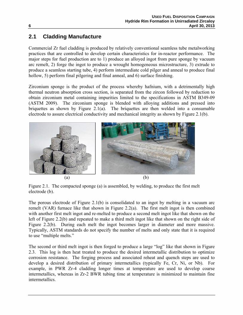
Zirconium sponge is the product of the process whereby hafnium, with a detrimentally high thermal neutron absorption cross section, is separated from the zircon followed by reduction to obtain zirconium metal containing impurities limited to the specifications in ASTM B349-09 (ASTM 2009). The zirconium sponge is blended with alloying additions and pressed into briquettes as shown by Figure 2.1(a). The briquettes are then welded into a consumable electrode to assure electrical conductivity and mechanical integrity as shown by Figure 2.1(b).
(a) (b)
Figure 2.1. The compacted sponge (a) is assembled, by welding, to produce the first melt electrode (b).
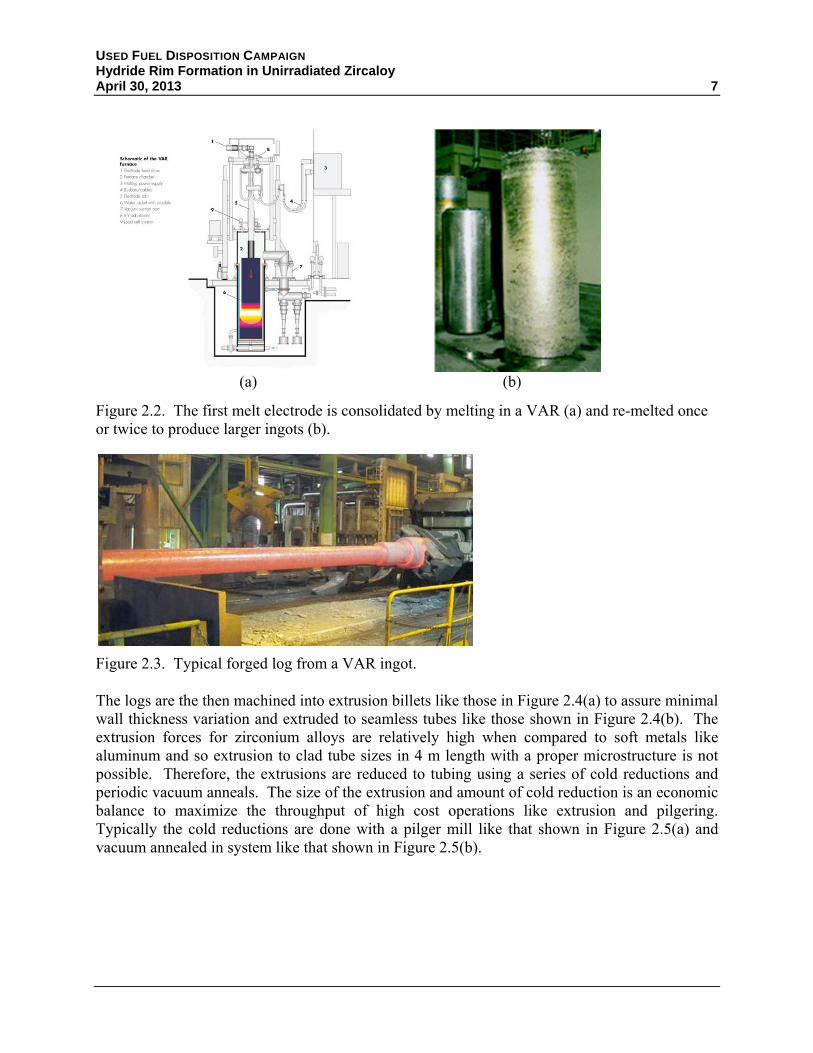
The porous electrode of Figure 2.1(b) is consolidated to an ingot by melting in a vacuum arc remelt (VAR) furnace like that shown in Figure 2.2(a). The first melt ingot is then combined with another first melt ingot and re-melted to produce a second melt ingot like that shown on the left of Figure 2.2(b) and repeated to make a third melt ingot like that shown on the right side of Figure 2.2(b). During each melt the ingot becomes larger in diameter and more massive. Typically, ASTM standards do not specify the number of melts and only state that it is required to use “multiple melts.”
The second or third melt ingot is then forged to produce a large “log” like that shown in Figure 2.3. This log is then heat treated to produce the desired intermetallic distribution to optimize corrosion resistance. The forging process and associated reheat and quench steps are used to develop a desired distribution of primary intermetallics (typically Fe, Cr, Ni, or Nb). For example, in PWR Zr-4 cladding longer times at temperature are used to develop coarse intermetallics, whereas in Zr-2 BWR tubing time at temperature is minimized to maintain fine intermetallics.
USED FUEL DISPOSITION CAMPAIGN Hydride Rim Formation in Unirradiated Zircaloy April 30, 2013 7
(a) (b)
Figure 2.2. The first melt electrode is consolidated by melting in a VAR (a) and re-melted once or twice to produce larger ingots (b).
Figure 2.3. Typical forged log from a VAR ingot.
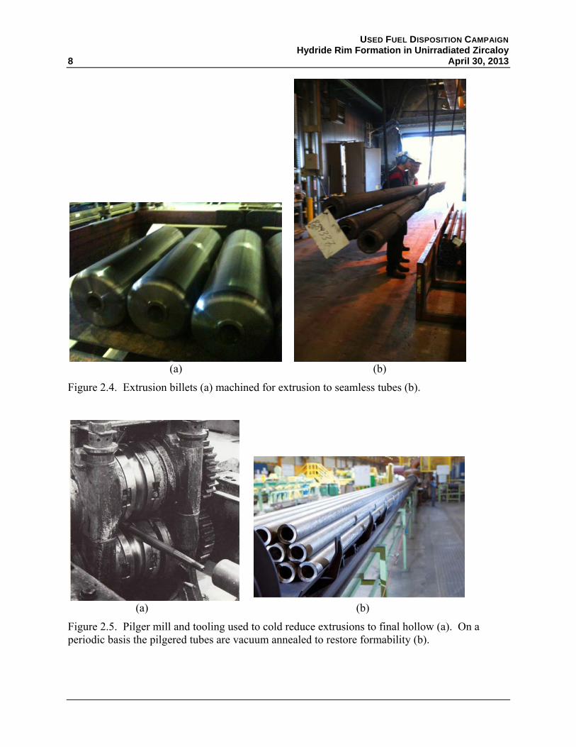
The logs are the then machined into extrusion billets like those in Figure 2.4(a) to assure minimal wall thickness variation and extruded to seamless tubes like those shown in Figure 2.4(b). The extrusion forces for zirconium alloys are relatively high when compared to soft metals like aluminum and so extrusion to clad tube sizes in 4 m length with a proper microstructure is not possible. Therefore, the extrusions are reduced to tubing using a series of cold reductions and periodic vacuum anneals. The size of the extrusion and amount of cold reduction is an economic balance to maximize the throughput of high cost operations like extrusion and pilgering. Typically the cold reductions are done with a pilger mill like that shown in Figure 2.5(a) and vacuum annealed in system like that shown in Figure 2.5(b).
USED FUEL DISPOSITION CAMPAIGN Hydride Rim Formation in Unirradiated Zircaloy
8 April 30, 2013
(a) (b)
Figure 2.4. Extrusion billets (a) machined for extrusion to seamless tubes (b).
(a) (b)
Figure 2.5. Pilger mill and tooling used to cold reduce extrusions to final hollow (a). On a periodic basis the pilgered tubes are vacuum annealed to restore formability (b).

USED FUEL DISPOSITION CAMPAIGN Hydride Rim Formation in Unirradiated Zircaloy April 30, 2013 9
Pilger tools are designed to develop a hydrostatic state of stress and allow high reduction of areas between anneals. Area reductions as high as 95 have been reported for Zr based alloys. Vacuum anneals are used to recover the formability between pilger reductions and can impact corrosion behavior. For cladding tubes, tight controls over the accumulated temperature and time are maintained and recorded as a term called “anneal parameter.” For PWR Zr-4, the ideal “anneal parameter” is much greater than the ideal parameter for BWR Zr-2. Even though the two alloys recover cold work under nearly the same conditions, the two cannot be annealed together due to “anneal parameter” constraints. The product of the intermediate pilger and anneals is a relatively thick-walled tube called a final hollow.
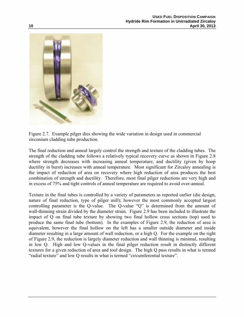
The final hollow dimensions and the final pilger process are critical steps in developing the cladding properties. Typically, a relationship based on the reduction of area and the amount of wall thinning strain is used to predict the final tube texture and strength. The final reduction is normally a proprietary step in the process and is defined by reduction of area, ratio of wall thinning to reduction of area, type of pilger mill, and the tool design. Examples of two final tube reductions and mills are given in Figure 2.6, although many variants of this process exist in commercial cladding production. As shown in Figure 2.7, tooling design can vary from ring dies (left) to multi-piece dies (right).
Figure 2.6. Examples of final pilger reductions and mills used for commercial fuel cladding production.
USED FUEL DISPOSITION CAMPAIGN Hydride Rim Formation in Unirradiated Zircaloy
10 April 30, 2013
Figure 2.7. Example pilger dies showing the wide variation in design used in commercial zirconium cladding tube production.
The final reduction and anneal largely control the strength and texture of the cladding tubes. The strength of the cladding tube follows a relatively typical recovery curve as shown in Figure 2.8 where strength decreases with increasing anneal temperature, and ductility (given by hoop ductility in burst) increases with anneal temperature. Most significant for Zircaloy annealing is the impact of reduction of area on recovery where high reduction of area produces the best combination of strength and ductility. Therefore, most final pilger reductions are very high and in excess of 75% and tight controls of anneal temperature are required to avoid over-anneal.
Texture in the final tubes is controlled by a variety of parameters as reported earlier (die design, nature of final reduction, type of pilger mill); however the most commonly accepted largest controlling parameter is the Q-value. The Q-value “Q” is determined from the amount of wall-thinning strain divided by the diameter strain. Figure 2.9 has been included to illustrate the impact of Q on final tube texture by showing two final hollow cross sections (top) used to produce the same final tube (bottom). In the examples of Figure 2.9, the reduction of area is equivalent, however the final hollow on the left has a smaller outside diameter and inside diameter resulting in a large amount of wall reduction, or a high Q. For the example on the right of Figure 2.9, the reduction is largely diameter reduction and wall thinning is minimal, resulting in low Q. High and low Q-values in the final pilger reduction result in distinctly different textures for a given reduction of area and tool design. The high Q pass results in what is termed “radial texture” and low Q results in what is termed “circumferential texture”.

USED FUEL DISPOSITION CAMPAIGN Hydride Rim Formation in Unirradiated Zircaloy April 30, 2013 11
Figure 2.8. Typical recovery curves for zirconium based alloys.
Figure 2.9. Illustration of two reductions used to produce the same tube (bottom) where the one on the left produces a radial texture and the one on the right produces a circumferential texture.
USED FUEL DISPOSITION CAMPAIGN Hydride Rim Formation in Unirradiated Zircaloy
12 April 30, 2013
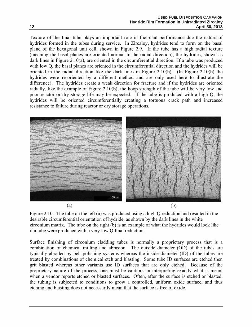
Texture of the final tube plays an important role in fuel-clad performance due the nature of hydrides formed in the tubes during service. In Zircaloy, hydrides tend to form on the basal plane of the hexagonal unit cell, shown in Figure 2.9. If the tube has a high radial texture (meaning the basal planes are oriented normal to the radial direction), the hydrides, shown as dark lines in Figure 2.10(a), are oriented in the circumferential direction. If a tube was produced with low Q, the basal planes are oriented in the circumferential direction and the hydrides will be oriented in the radial direction like the dark lines in Figure 2.10(b). (In Figure 2.10(b) the hydrides were re-oriented by a different method and are only used here to illustrate the difference). The hydrides create a weak direction for fracture and if the hydrides are oriented radially, like the example of Figure 2.10(b), the hoop strength of the tube will be very low and poor reactor or dry storage life may be expected. If the tube is produced with a high Q, the hydrides will be oriented circumferentially creating a tortuous crack path and increased resistance to failure during reactor or dry storage operations.
(a) (b)
Figure 2.10. The tube on the left (a) was produced using a high Q reduction and resulted in the desirable circumferential orientation of hydride, as shown by the dark lines in the white zirconium matrix. The tube on the right (b) is an example of what the hydrides would look like if a tube were produced with a very low Q final reduction.
Surface finishing of zirconium cladding tubes is normally a proprietary process that is a combination of chemical milling and abrasion. The outside diameter (OD) of the tubes are typically abraded by belt polishing systems whereas the inside diameter (ID) of the tubes are treated by combinations of chemical etch and blasting. Some tube ID surfaces are etched then grit blasted whereas other variants use ID surfaces that are only etched. Because of the proprietary nature of the process, one must be cautious in interpreting exactly what is meant when a vendor reports etched or blasted surfaces. Often, after the surface is etched or blasted, the tubing is subjected to conditions to grow a controlled, uniform oxide surface, and thus etching and blasting does not necessarily mean that the surface is free of oxide.

USED FUEL DISPOSITION CAMPAIGN Hydride Rim Formation in Unirradiated Zircaloy April 30, 2013 13
Over many years of development and optimization, fuel cladding tubes have been produced in a wide variety of strength and ductility levels. This is done by controlling the final tube anneal to produce three different levels of “anneal” called 1) cold work stress relief anneal (CWSR), 2) partial recrystallization anneal (PRXA), and 3) full recrystallization anneal (RXA). The CWSR and PRXA are normally higher strength conditions used in PWR cladding while RXA is typically used for Zr-2 in BWRs.
The state or level of anneal is determined from a recovery curve as shown in Figure 2.8. As the yield strength is tracked with anneal temperature (in Figure 2.8), the curve initially starts with a relatively shallow slope up to about 930°F. This flat initial slope is known as “recovery and reorder” of dislocation structures or “stress relief.” Tubes produced to CWSR are annealed in the initial region of the recovery curve and are typically annealed to the highest temperature possible to maximize ductility without lowering the strength. For the 80% cold work curve in Figure 2.8, the CWSR anneal temperature would be 930°F or less. The PRXA anneal occurs in the steep region of the recovery curve (about 930 to 1067°F in Figure 2.8). During the PRXA portion of the curve, the recovered microstructure begins to recrystallize into new grains. At low temperatures (930+°F), there is a small fraction of recrystallized grains and as the temperature is increased (up to 1067°F) the number of recrystallized grain increases; between 930°F and 1067°F the annealed tube would be considered PRXA. Above 1067°F in Figure 2.8, 100% of the microstructure would be recrystallized and the tube would be considered to be RXA.
It is important to note that small alloy chemistry and level of cold work differences change the recovery curve, as shown in Figure 2.8 for tubes cold worked 80% and 53%. Therefore, temperatures are not specified for the CWSR, PRXA, and RXA condition and level of anneal is determined from mechanical properties (strength and ductility) or microstructural sampling (or both).
2.2 Hydrogen Uptake
During reactor operations, the Zircaloy cladding is in contact with the high temperature reactor and pressure coolant (water and/or steam) and corrodes according to the reaction
2 → 2
Some fraction, called the hydrogen uptake ratio, of the hydrogen is absorbed in the cladding. The chemical composition of the alloy is a primary factor affecting the rate of corrosion and thus hydrogen generation. Newer alloys such as ZIRLO™ and M5® have been developed specifically to reduce the corrosion rate of the cladding. However, in PWRs, a hydrogen overpressure is applied to limit corrosion and, combined with radiolytically-generated hydrogen, can still supply a source of hydrogen for the cladding to uptake.
It is reported (Colas 2012) that for Zr-4, 10-20% of the hydrogen liberated from corrosion is typically absorbed into the cladding. While the newer alloys with the addition of Nb significantly reduce the corrosion rate, they do not necessarily reduce the hydrogen uptake ratio. In fact, Kim (Kim and Kim 1999) showed that cladding pickled to remove much of the surface

USED FUEL DISPOSITION CAMPAIGN Hydride Rim Formation in Unirradiated Zircaloy
14 April 30, 2013
oxide and then exposed to flowing hydrogen gas at 300°C exhibited weight gain in the order ZIRLO™ > Zr-2 >Zr-4. The hydrogen taken up will precipitate circumferentially or radially depending on the cladding texture as discussed in Section 2.1.
In addition to the alloy composition and microstructure, the presence and characteristics of an oxide film on the cladding surface will have a large influence on the hydrogen uptake (Sawatzky 1960). Colas (Colas 2012) reported that the diffusion coefficient of hydrogen is 108 times slower in oxide than in the zirconium matrix. This is demonstrated by Chen (Chen et al. 2009) when they noted that a protective oxide layer acted as a very effective diffusion barrier in their attempts to desorb hydrogen from zirconium hydride. It is important to remember that once the oxide exceeds a critical thickness, it begins to fracture, and it is hypothesized that increased hydriding occurs via hydrogen transport through these flaws as opposed to diffusion through a thick oxide layer (Cox 1999). Oxide build-up during the pre-hydriding process is possible if the hydrogen contains even traces of oxygen or water vapor. Bruni (Bruni et al. 2011) modeled that a partial pressure of 8.2 × 10⁻⁹ atm is required to hydride pure zirconium at 300°C, whereas even minute quantities of water vapor increase the required partial pressure to 6.2 × 10⁻² atm. The diffusion of hydrogen through zirconium hydride is a factor of 100 times slower than in the zirconium matrix.
Other factors such as residual stress, the ratio of the area-to-volume exposed to corrosion, and water chemistry will affect hydrogen uptake and precipitation. However, for the purposes of this study where empty cladding is to be loaded with hydrogen in a gas atmosphere, those factors should have little or no influence.
2.3 Hydrogen Redistribution
Sawatzky (Sawatzky 1960) performed experiments with Zr-2 cylinders 1.2 cm in diameter and 2.5 cm in length. The samples were hydrided by heating the samples at 900°C and exposing them to the desired amount of hydrogen gas. A homogeneous hydrogen distribution was obtained by annealing for six hours. One end of the cylinder was then heated to 500°C and the other end was held at 300°C and held for 44 days to arrive at the steady-state hydrogen distribution predicted by his model.
Similar tests were run with larger temperature gradients (130°C - 477°C and 157°C - 454°C for 34 and 41 days, respectively. The first sample had an initial uniform hydrogen concentration of 130 wppm (parts per million by weight). After the 34-day anneal, the portion of the sample where the local temperature exceeded 250°C showed hydrogen concentrations of approximately 50 wppm and decreasing as the temperature increased. Similarly, the cooler portions of the sample had local hydrogen concentrations in excess of 200 wppm and as high as approximately 550 wppm. Similar redistribution was observed in the 41-day annealed sample containing an initial hydrogen concentration of 64 wppm. These samples had not yet reached steady-state hydrogen distributions, but redistribution was clearly evident, with the expected result that hydrogen in solution diffuses down a thermal gradient and concentrates in cold regions. Hong (Hong et al. 1998) questions the applicability of the Sawatzky model and results under the

USED FUEL DISPOSITION CAMPAIGN Hydride Rim Formation in Unirradiated Zircaloy April 30, 2013 15
conditions cladding is expected to experience under normal reactor operations where the temperature gradients are more of the order 300°C - 340°C.
Redistribution of hydrogen is actually a very complex process since the redistribution is affected not only by thermal gradients, but also by concentration and stress gradients, which in turn are affected by factors such as radiation damage, hydride precipitates, etc. Similarly, the various models proposed and interpretation of data has resulted in significant differences in calculation of the diffusion coefficient of hydrogen in Zircaloy. Kammenzind (Kammenzind et al. 1996) calculated the diffusion coefficient in Zr-4 as
D = 0.8 × 10⁻³ exp (-7955/RT)
where D = diffusion coefficient (cm2/sec) R = ideal gas constant T = temperature (K)
Colas (Colas 2012) used this temperature-dependent diffusion coefficient to calculate the distance that hydrogen could diffuse in one hour in Zr-4. These results are presented in Table 2.2. It is seen that for the temperatures of interest not only to drying applications, but the majority of experiments involving PH cladding that hydrogen can readily diffuse the entire thickness of the cladding in one hour. However, based on the results of Sawatzky (Sawatky 1960) and Hong (Hong et al. 1998), it is important to stress that the times to achieve true steady-state distributions are much longer or require much higher temperatures.
Table 2.2. Hydrogen diffusion distances in Zr-4 in 1 hour.
Temperature (°C)
Solubility (wppm)
Diffusion Coefficient (cm2/s)
Diffusion Distance
100 2-5 10-8 60 µm 200 15-30 2×10⁻⁷ 270 µm 300 80-90 10-6 600 µm 400 250 3×10⁻⁶ 1 mm

USED FUEL DISPOSITION CAMPAIGN Hydride Rim Formation in Unirradiated Zircaloy April 30, 2013 17
3. EXPERIMENTAL SETUP
The work thus far has focused on developing the means to obtain the hydride rim in unirradiated cladding to match the observations of hydride distribution in high burnup cladding. Two distinct efforts were undertaken, one to pre-hydride samples at low temperature to obtain the rim directly and the other to pre-hydride samples in “typical” means (i.e., uniform distribution) and attempt to redistribute the hydrides by applying a thermal gradient. Efforts have concentrated on using low (≤350°C) temperature methods so that this process could be used to hydride cladding that is pre-irradiated at Oak Ridge National Laboratory without annealing out the induced radiation damage that is annealed out in relatively short times at temperatures above 400°C.
3.1 Hydrogen Loading Tests
Unirradiated Zircaloy samples were pre-hydrided using two methods:
1. A tube furnace heated to 500°C using a known volume/pressure of hydrogen gas to pre-load with hydrogen uniformly into the samples (e.g., following ASTM B11-02 [ASTM 2007] methods).
2. A cold wall hydrogen gas furnace capable of running both argon and hydrogen continuously into the furnace to maintain a constant gas concentration to heterogeneously load samples with hydrogen at temperatures up to 350°C.
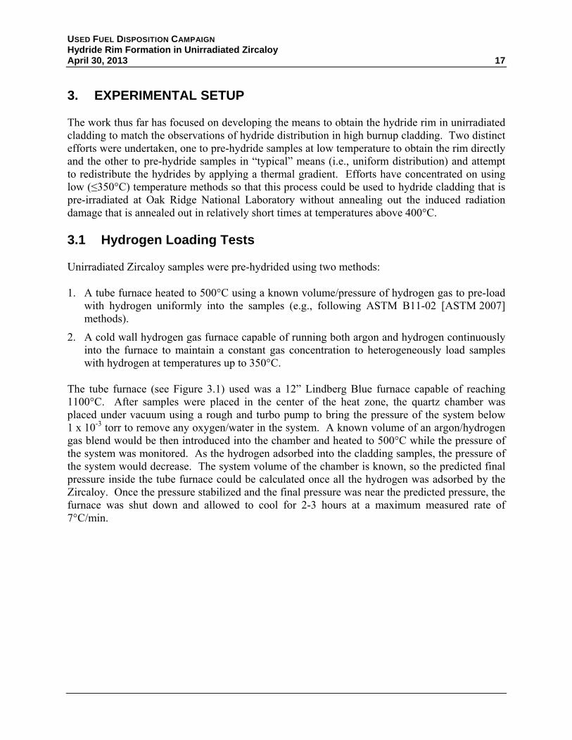
The tube furnace (see Figure 3.1) used was a 12” Lindberg Blue furnace capable of reaching 1100°C. After samples were placed in the center of the heat zone, the quartz chamber was placed under vacuum using a rough and turbo pump to bring the pressure of the system below 1 x 10⁻³ torr to remove any oxygen/water in the system. A known volume of an argon/hydrogen gas blend would be then introduced into the chamber and heated to 500°C while the pressure of the system was monitored. As the hydrogen adsorbed into the cladding samples, the pressure of the system would decrease. The system volume of the chamber is known, so the predicted final pressure inside the tube furnace could be calculated once all the hydrogen was adsorbed by the Zircaloy. Once the pressure stabilized and the final pressure was near the predicted pressure, the furnace was shut down and allowed to cool for 2-3 hours at a maximum measured rate of 7°C/min.
USED FUEL DISPOSITION CAMPAIGN Hydride Rim Formation in Unirradiated Zircaloy
18 April 30, 2013
(a) Lindberg Blue Furnace (b) Quartz Tube Inside Furnace
Figure 3.1. Tube furnace for pre-hydriding unirradiated Zircaloy.
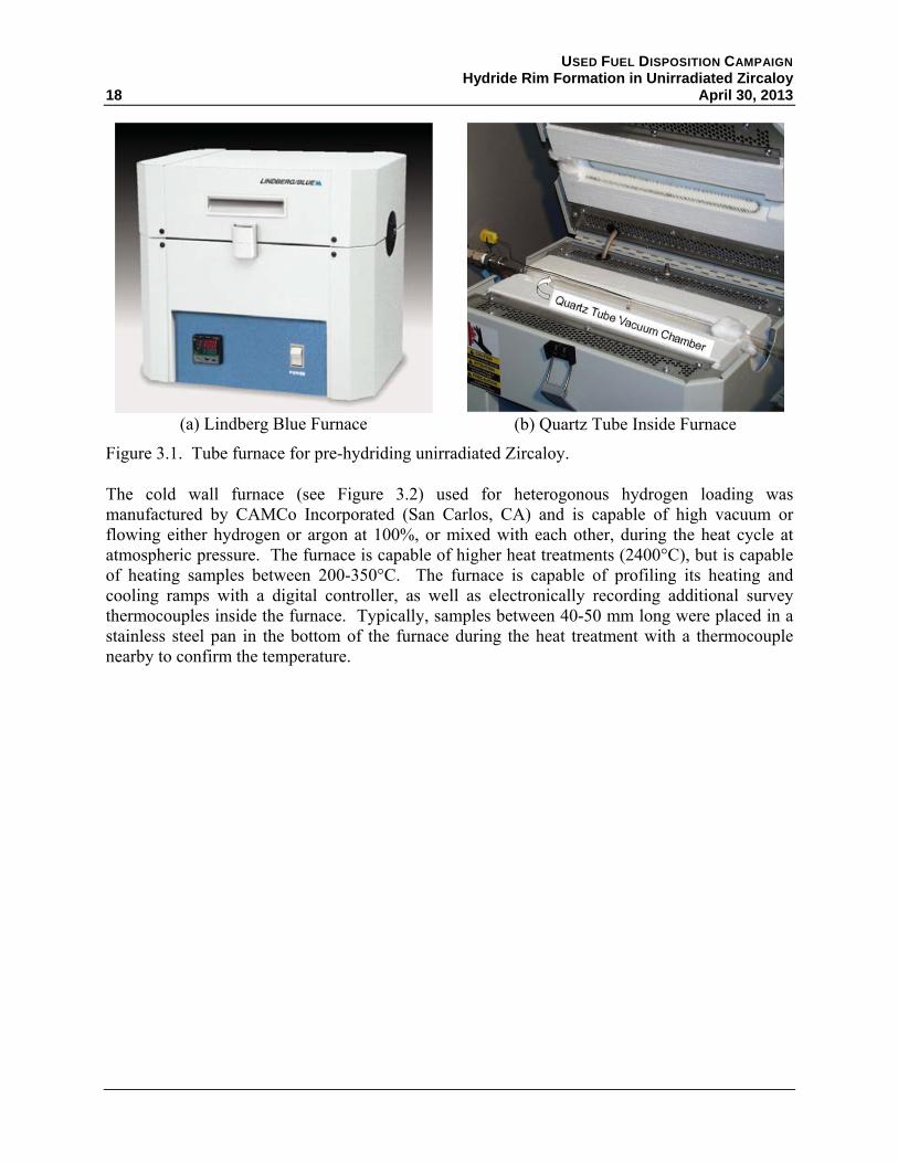
The cold wall furnace (see Figure 3.2) used for heterogonous hydrogen loading was manufactured by CAMCo Incorporated (San Carlos, CA) and is capable of high vacuum or flowing either hydrogen or argon at 100%, or mixed with each other, during the heat cycle at atmospheric pressure. The furnace is capable of higher heat treatments (2400°C), but is capable of heating samples between 200-350°C. The furnace is capable of profiling its heating and cooling ramps with a digital controller, as well as electronically recording additional survey thermocouples inside the furnace. Typically, samples between 40-50 mm long were placed in a stainless steel pan in the bottom of the furnace during the heat treatment with a thermocouple nearby to confirm the temperature.
USED FUEL DISPOSITION CAMPAIGN Hydride Rim Formation in Unirradiated Zircaloy April 30, 2013 19
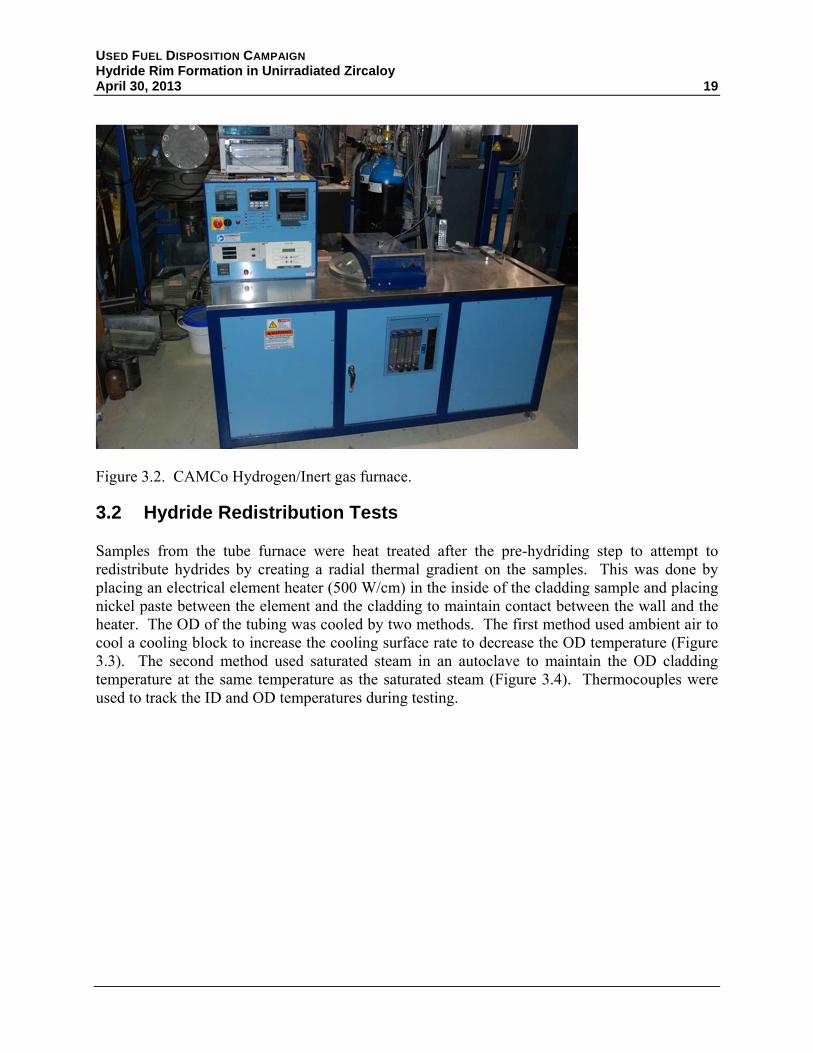
Figure 3.2. CAMCo Hydrogen/Inert gas furnace.
3.2 Hydride Redistribution Tests
Samples from the tube furnace were heat treated after the pre-hydriding step to attempt to redistribute hydrides by creating a radial thermal gradient on the samples. This was done by placing an electrical element heater (500 W/cm) in the inside of the cladding sample and placing nickel paste between the element and the cladding to maintain contact between the wall and the heater. The OD of the tubing was cooled by two methods. The first method used ambient air to cool a cooling block to increase the cooling surface rate to decrease the OD temperature (Figure 3.3). The second method used saturated steam in an autoclave to maintain the OD cladding temperature at the same temperature as the saturated steam (Figure 3.4). Thermocouples were used to track the ID and OD temperatures during testing.

USED FUEL DISPOSITION CAMPAIGN Hydride Rim Formation in Unirradiated Zircaloy
20 April 30, 2013
Figure 3.3. Cooling block method.
Figure 3.4. Autoclave method.
Heater (390-420°C)
Saturated Steam (300-330°C)
Cladding
Autoclave
Swagelok

USED FUEL DISPOSITION CAMPAIGN Hydride Rim Formation in Unirradiated Zircaloy April 30, 2013 21
3.3 Post-test Examinations
Radial cut tubing samples approximately 8 mm in length were taken from the test specimens for destructive and optical examination. A metallographic saw (Figure 3.5) wet-cut subsamples with a diamond-impregnated copper blade using deionized (DI) water as the blade coolant.
(a) Buehler Isomet® Sample Cutter (b) Typical 8 mm long radial cut tubing sample
Figure 3.5. Metallographic sample saw and radial cut specimen.
Cut radial samples were destructively analyzed for the total hydrogen content in the Zircaloy samples by inert gas fusion, using an analyzer (Figure 3.6) made by the LECO Corporation (St. Joseph, MI). Analyses were performed both at PNNL and at ATI Wah Chang Analytical Services (Albany, OR). Instruments were calibrated prior to each analysis using manufacturer-supplied standards. Cut samples were divided again either into 2 or 4 additional samples to produce analytical duplicates or to verify the uniformity of the hydrogen concentration around the circumference.

USED FUEL DISPOSITION CAMPAIGN Hydride Rim Formation in Unirradiated Zircaloy
22 April 30, 2013
Figure 3.6. LECO Series 400 inert gas fusion analyzer.
Samples were also examined in the radial direction by metallographic optical microscopy to confirm the results of the gas fusion analysis and qualitatively assess how the hydrides were deposited on the samples. Samples were placed in epoxy circular mounts and wet-polished using a metallographic polisher (Figure 3.7). Silicon carbide (SiC) grit paper with DI water was used, starting with 400 grit and repeating with ever finer grit sizes up to 1200. The number of polishes required varied depending on how scratches were removed during polishing. In some cases, a vibratory polisher was used instead. After polishing, hydrides should be visible but can be difficult to discern from the metal (Figure 3.8). After polishing was completed, a hydrofluoric-nitric acid etch polish was used to preferentially etch the hydrides over the metal. The hydrides appear as dark crevices in the metal surface in an etched sample. This metallographic etch is typically performed while rubbing the mount onto a cotton swab that contains the etchant and is quickly rinsed afterwards. Most of the literature discusses using higher concentrations of hydrofluoric than what was used on this task (4-5 wt%). However, samples were easily over-etched at this concentration making discerning the hydride present difficult. It was discovered that lowering the hydrofluoric concentration to between 0.5 – 1 wt% was a more robust etching solution and minimized over-etching of samples afterwards.

USED FUEL DISPOSITION CAMPAIGN Hydride Rim Formation in Unirradiated Zircaloy April 30, 2013 23
(a) Buehler MicroMet® 1000 Polisher
(b) Buehler Vibratory Polisher
Figure 3.7. Metallographic polishing equipment used.
(a) Polished with SiC up to 1200 Grit
(b) Followed with HF/HNO3 Etch
Figure 3.8. Metallographic images of hydrided Zircaloy (a) polished with SiC 400-1200 grit paper and (b) followed by a 0.5 wt% HF – 30 wt% HNO3 etch while polishing with cotton swab and rinsed in DI water.


USED FUEL DISPOSITION CAMPAIGN Hydride Rim Formation in Unirradiated Zircaloy April 30, 2013 25
4. RESULTS
This section describes the results of both the pre-hydriding (hydrogen loading) tests and the few tests run to examine hydride redistribution.
4.1 Hydrogen Loading Tests
The purpose of these initial tests was to determine if hydrogen could be added to Zr-4 cladding samples at temperatures below 400°C. This may be necessary if it is determined that it is better to first irradiate cladding to obtain the radiation damage and then hydride the cladding. ASTM International Standard B811-02 Appendix A2 (ASTM 2007) states that hydrogen is introduced by methods such as autoclaving in steam or lithium hydroxide, electrolytic deposition, or absorption of hydrogen gas. The temperatures shall not exceed 414°C and “the method of hydriding shall not result in excessive hydride concentration on the surface.” At these high temperatures, radiation damage could be annealed and would thus defeat the purpose of the irradiation.
Samples 40-50 mm long were cut from an archived cladding sample and heat treated in a hydrogen furnace capable of using up to 100% hydrogen gas to vent the heat zone and prevent oxidation. The samples were treated at temperatures between 200°C-350°C; well below the short-term anneal temperature of the cladding. Hydrogen absorbance was measured directly by a LECO hydrogen analyzer at PNNL or at ATI Wah Chang (Albany, Oregon) and by metallographic examination for hydrogen platelet structure.
The results are grouped by the test instruction (TI) written to govern the conditions the samples were tested under and the purpose of that specific test is identified.
4.1.1 Initial Low Temperature Hydriding
The use of H2 gas to pre-hydride unirradiated Zircaloy has been used for decades. However, most applications are performed at high temperatures (400°C or higher) in order to obtain the desired loading within very short times. Similarly, most pre-hydriding is either done under temperature cycling or is followed by a high temperature anneal to facilitate a homogeneous distribution. The purpose of these initial tests was to determine how long samples would need to be treated at lower temperatures to obtain the desired hydrogen loading.
Single Zircaloy samples were treated at temperatures between 200°C-350°C for either 8 or 24 hours as shown in Table 4.1. Hydrogen absorbance was measured directly by a LECO hydrogen analyzer at PNNL or at ATI Wah Chang (Albany, Oregon) and by metallographic examination for hydrogen platelet structure.
USED FUEL DISPOSITION CAMPAIGN Hydride Rim Formation in Unirradiated Zircaloy
26 April 30, 2013
Table 4.1. Hydrogen furnace treatment test matrix.
Temperature (°C) Heat Treatment Period 200 24 hours 250 24 hours 275 24 hours 300 8 & 24 hours 350 8 hour
The results of the LECO hydrogen concentration analyses for the samples in Table 4.1 are provided in Table 4.2. All samples in this test matrix were soaked in one atmosphere of 100% H2. No significant weight gain was observed until the temperatures reached 300°C. The sample hydrided for 8 hours at 350°C was completely converted to zirconium hydride and crumbled into powder. As expected, increasing the temperature increased the rate of hydrogen absorbance as demonstrated in Figure 4.1. The important conclusion is that it is possible to hydride cladding at relatively low temperatures in a 100% H2 atmosphere.
Table 4.2. Hydrogen uptake results.
Furnace Temperature
(°C)
Hydrogen Concentration (wppm) 8 hour Soak 24 hour Soak
Ave. Std. Dev. Ave. Std. Dev. 200 --- --- 108 14 250 --- --- 142 97 275 --- --- 405 16 300 308 6 457 98 350 22700 311 --- ---

USED FUEL DISPOSITION CAMPAIGN Hydride Rim Formation in Unirradiated Zircaloy April 30, 2013 27
Figure 4.1. Comparison of hydrogen uptake in 100% hydrogen after 24 hours as function of temperature.
Metallography of the samples was performed on samples treated at 275°C and 300°C at 24 hours to confirm the presence of hydrides. Initial examination of the samples failed to show any hydrides present and it was thought that the relatively rapid cool down following the heat treatment did not allow for hydride platelets to coalesce. However, after subsequent test results indicated that this treatment should have formed observable hydrides, the samples were repolished and etched with a less aggressive etchant. Hydrides were identified (Figure 4.2 and Figure 4.3), but not as clearly as would be expected for samples containing greater than 400 wppm hydrogen. The hydrides observed were not very elongated and would have been difficult to observe in samples that were over-etched. Cooling rate can significantly impact the size of hydrides formed. For these tests, the cooling rate was not controlled and likely occurred at a rate > 10°C/min. Cooling rate became a significant parameter for subsequent tests.

USED FUEL DISPOSITION CAMPAIGN Hydride Rim Formation in Unirradiated Zircaloy
28 April 30, 2013
(a) Entire Wall
(b) Near Outside Wall
Figure 4.2. Metallographic images of 275°C sample after 24 hours.
(a) Near Outside Wall
(b) Near Inside Wall
Figure 4.3. Metallographic images of 300°C sample after 24 hours.
4.1.2 TI-1: Confirm 300°C Results with Elevated Temperature Heat Soak and Controlled Cooling in Argon
As shown in Table 4.2, hydrogen analysis showed significant hydrogen adsorption in samples pre-hydrided at 300°C for 24 hours in a 1 atm hydrogen gas environment. However, the hydrides were not the typical, large platelets observed and reported for other PH or irradiated cladding tests (Billone et al. 2008, 2013). ASTM B811 (ASTM 2007) discusses the need to heat treat samples at 399°C ± 14°C for 5 ± 1 hours and cool samples afterwards at a rate not to exceed 14°C/min. These treatment steps are necessary to:
1. Allow migration of hydrogen from the outside surface into the inner material
2. Cool at a rate slow enough to allow hydride formation to grow in the grain boundaries and not quench them within the grains themselves.
USED FUEL DISPOSITION CAMPAIGN Hydride Rim Formation in Unirradiated Zircaloy April 30, 2013 29
The purpose of the TI-1 tests was to pre-hydride three Zircaloy samples of varying size at the same time in a hydrogen atmosphere for 24 hours at 300°C, the same conditions as the tests described in Section 4.1.1. However, these samples were heat treated in an argon atmosphere immediately afterwards at an elevated temperature following the guidelines of ASTM B811 (ASTM 2007) to attempt to produce larger hydrides in the grain boundaries. The samples were then cooled at a significantly slower rate (1.5°C/min) while in argon until they reached room temperature. Samples were analyzed for hydrogen by gas inert fusion and by metallographic polishing followed by a chemical etch.
The results of the hydrogen analyses of the TI-1 samples as performed by ATI Wah Chang Laboratory Services are found in Table 4.3. When compared to the results in Table 4.2, the hydrogen concentration in these samples was significantly lower than the 400+ wppm of the previous samples. Initially, it was suspected that treating the samples in argon could have possibly lowered the concentration by de-hydriding the samples at the higher temperature. However, it should be observed that the heat treatment did assist in distributing the hydrogen more homogenously throughout the samples, as shown in the lower standard deviation results.
Table 4.3. Hydrogen analysis results for TI-1.
Sample Id
Cladding Dimension (in) Hydrogen Concentration
(wppm)
Outside Diameter Inside
Diameter Average Standard Deviation
1 0.368 0.317 255 7 2 0.373 0.329 235 35 3 0.451 0.380 215 7
Metallographic observations were performed on all three samples. As expected, the heat treatment and slower cooling rate distributed the hydrides evenly through the sample and created hydrides that were very elongated (Figure 4.4 and Figure 4.5). It was observed that the hydride concentration was slightly higher at the edge of the OD.
USED FUEL DISPOSITION CAMPAIGN Hydride Rim Formation in Unirradiated Zircaloy
30 April 30, 2013
Figure 4.4. Metallographic image of transverse wall of sample 1 after etch.
Figure 4.5. Metallographic image of transverse wall of sample 2 after etch.
USED FUEL DISPOSITION CAMPAIGN Hydride Rim Formation in Unirradiated Zircaloy April 30, 2013 31
4.1.3 TI-2: Repeat of Test TI-1 without Elevated Heat Soak
Despite the lower concentration of hydrogen present in the samples, the high temperature anneal under argon and the controlled cool down implemented in TI-1 increased the size of hydride formed. The purpose of the tests in TI-2 was to observe the impact the argon anneal at 400°C had on the growth of hydrides by deleting this step from the heat treatment. It was also of interest to see if the hydrogen concentrations between this test and the previous test were similar, or if the extended heat treatment in argon contributed to the overall lower hydrogen concentration values measured.
As in TI-1, three Zircaloy samples of varying size were placed in the CAMCo furnace at the same time in a hydrogen atmosphere for 24 hours at 300°C. However, this TI called for the samples to be cooled down immediately following the hydrogen loading, eliminating annealing at 1.5°C/min in argon until they reached room temperature. As before, the samples were analyzed for hydrogen by gas inert fusion and by metallographic polishing followed by a chemical etch.
The results of the hydrogen analyses of the TI-2 samples as performed by ATI Wah Chang Laboratory Services are found in Table 4.4. Overall, the hydrogen concentration observed was still significantly lower than the sample results reported in Table 4.2, even without the argon heat treatment at 400°C. A check of the furnace anneal log book showed that the hydrogen gas flow rate for TI-1 and TI-2 was only half of that used for the testing performed in fiscal year 2012. This impact will be later explored in TI-3.
Table 4.4. Hydrogen analysis results for TI-2.
Sample
Cladding Dimension (in) Hydrogen Concentration (wppm) Outside
Diameter Inside Diameter Average Standard Deviation
4 0.368 0.317 170 14 5 0.373 0.329 140 14 6 0.451 0.380 130 ---*
* The duplicate hydrogen concentration measurements for Sample 6 were identical.
Metallographic observations of the samples were performed on all three samples (Figure 4.6 through Figure 4.8). The results were similar to that from TI-1, showing that the cooling rate, and not the argon anneal, was needed to grow hydrides to significant size. It was also observed that high concentrations of hydride were found on localized pockets on the OD as shown in Figure 4.9, giving the appearance of the desired rim formation. However, as this was a very localized effect, it was determined that this high concentration was most likely caused by a defect. These defects could be localized areas of stress caused by handling damage, or just weak areas in the oxide layer where hydrogen was able to penetrate more easily into the cladding samples, resulting in localized high concentrations of hydrides. This showed the significance of surface conditions, a significance that has yet to be explored.
USED FUEL DISPOSITION CAMPAIGN Hydride Rim Formation in Unirradiated Zircaloy
32 April 30, 2013
Figure 4.6. Metallographic image of transverse wall of sample 4 after etch.
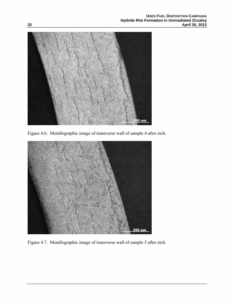
Figure 4.7. Metallographic image of transverse wall of sample 5 after etch.

USED FUEL DISPOSITION CAMPAIGN Hydride Rim Formation in Unirradiated Zircaloy April 30, 2013 33
Figure 4.8. Metallographic image of transverse wall of sample 6 after etch.
Figure 4.9. Significant hydride formation near surface defect on OD.

USED FUEL DISPOSITION CAMPAIGN Hydride Rim Formation in Unirradiated Zircaloy
34 April 30, 2013
4.1.4 TI-3: Varying of Surface Finish of Cladding
The purpose of this TI was to understand how surface finishes impact hydrogen adsorption and how a rapid cooling rate may impact the creation of the large hydrides seen in TI-1 and TI-2. The hydrogen gas flow rate was increased to the original rates used in the initial tests (Section 4.1.1) to verify that flow rate was affecting the hydrogen adsorption.
For this test, two sets of three Zircaloy tubing samples of similar size used in TI-1 and TI-2 were heated in 100% of hydrogen at 300°C for 24 hr. Each set of samples had a different surface condition:
a. Grit blasted surface condition for the OD, while maintaining the as-fabricated chemical etch polish (meaning controlled oxide layer) on the ID
b. Chemical etched surface condition for the OD and ID, followed by an hour soak in hot deionized water (to grow controlled oxide layers)
c. Standard manufactured surface condition, which has
i. a ground polished OD using SiC belts
ii. a chemically etched ID polish
At the end of 24 hours, hydrogen gas continued to flow while the samples were rapidly cooled as done for the samples in Section 4.1.1.
The results of the hydrogen analyses of the TI-3 samples as performed by ATI Wah Chang Laboratory Services are found in Table 4.5. The following observations from the results were made:
1. Increasing the hydrogen flow rate into the furnace significantly increased the hydrogen concentration in the samples. This implied the system in the furnace was more dynamic than believed.
2. Chemical etching the material in 4 wt% HF and 30 wt% HNO3, followed by a soak in deionized water at elevated temperatures (60-100°C) creates a significant barrier to hydrogen gas at the temperature range being examined (300-350°C). The etched samples show little hydrogen adsorption during the test. This implies that almost all hydrogen uptake in our samples has been through the OD since all samples have chemical etched IDs from the manufacturer.
3. The blasted finish on the OD improved hydrogen gas adsorption compared to the manufactured finish. However, the variation also increases as well, implying that more control is required on the blasting process if this method is selected to improve hydrogen adsorption.

USED FUEL DISPOSITION CAMPAIGN Hydride Rim Formation in Unirradiated Zircaloy April 30, 2013 35
Table 4.5. Hydrogen analysis results for TI-3.
Sample Surface
Condition
Cladding Dimension (in) Hydrogen Concentration
(wppm) Outside
Diameter Inside
Diameter Average Standard Deviation
7a Blasted OD 0.368 0.317 375 92 7b Etched 0.368 0.317 14 1 7c As-Is 0.368 0.317 320 42 8a Blasted OD 0.451 0.380 220 42 8b Etched 0.451 0.380 15 1 8c As-Is 0.451 0.380 180 28
Metallographic examination was performed on all six samples (Figure 4.10 through Figure 4.15). The results were similar to those for the samples in Section 4.1.1, showing that hydrides within the interior were not as elongated as those with a slower cooling rate. However, the concentration of hydrides along the OD surface for the blasted samples was not expected. While the hydrogen adsorption was expected to increase, the concentration on the OD implied something suspected from the etching samples results.
1. By stripping the oxide layer off the OD surface, the gas flow into the metal increased, but at a rate that exceeded the solubility of the metal and began to precipitate hydrides.
2. The diffusion of hydrogen into these samples appears to be one-way, with the etched ID preventing hydrogen adsorption through at the temperature range of interest.
3. The ground finished shows some hydride concentration near the OD surface, but not to the extent as the blasted surface does. This likely is due to the fact that grinding of Zircaloy is performed wet and stored in DI water afterwards, allowing an oxide layer to form.
This shows that surface condition plays a significant role in the adsorption of hydrogen and that a consistent method for treating the surface prior to adsorption needs to be developed. It should be noted that not all manufacturers chemically etch their tubing and the manufacturers likely have different methods of cleaning tubing after grinding and blasting. Understanding the finishing of received sample material will be critical for all future testing.

USED FUEL DISPOSITION CAMPAIGN Hydride Rim Formation in Unirradiated Zircaloy
36 April 30, 2013
Figure 4.10. Blasted OD/chemical etched ID condition for sample 7.
Figure 4.11. Chemical etched OD and ID for sample 7.

USED FUEL DISPOSITION CAMPAIGN Hydride Rim Formation in Unirradiated Zircaloy April 30, 2013 37
Figure 4.12. As-received finish: belt ground OD/etched ID for sample 7.
Figure 4.13. Blasted OD/Chemical etched ID condition for sample 8.
USED FUEL DISPOSITION CAMPAIGN Hydride Rim Formation in Unirradiated Zircaloy
38 April 30, 2013
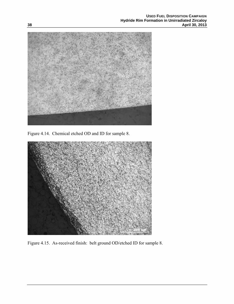
Figure 4.14. Chemical etched OD and ID for sample 8.
Figure 4.15. As-received finish: belt ground OD/etched ID for sample 8.

USED FUEL DISPOSITION CAMPAIGN Hydride Rim Formation in Unirradiated Zircaloy April 30, 2013 39
4.1.5 TI-4: Effects on Performing Multiple Cycles on Hydrogen Adsorption
The purpose of this TI was to understand the impact of multiple heat treating steps to promote hydrogen adsorption on the OD of tubing samples with grit blasted OD and etched polished ID. The results from TI-3 indicate that ground/blasted finishes preferentially adsorbed hydrogen over tubing with an etched polish finish. The samples with ground/grit polishes, but etched IDs, had a high concentration of hydrides on the OD, but a lower concentration in the rest of the wall. The theory of the TI-4 testing was to allow hydrogen to enter the material on the OD and to quench the hydrides at the OD before the hydrogen could diffuse throughout the wall. By repeating the cycles, it is believed that the OD would continue to grow a hydride rim while minimizing the hydrides in the rest of the sample. One major concern, however, is that this cycling process could essentially shut down the hydrogen pickup over time from build-up of an oxide layer occurring from running multiple cycles with impurities present in the hydrogen gas or by exposing the samples to air between cycles. The TI plan had the following steps:
1. Two sets of three Zircaloy tubing samples of similar size were OD grit blasted to remove the existing OD finish, while maintaining the etch polish ID. Samples were cleaned afterwards with acetone and handled with cotton gloves.
2. The samples were heated and cooled in 100% hydrogen at 300°C for 8 hour periods for multiple cycles. One tube from each set was heat treated once (i.e., removed after 8 hours), another sample twice, and the final sample a third time.
3. Optical examination and hydrogen measurement by inert gas fusion were performed on the pre-hydrided samples.
The results of the hydrogen analyses of the TI-4 samples as performed by ATI Wah Chang Laboratory Services are found in Table 4.6. While hydrogen increased significantly between the first and second cycle, hydrogen pickup stopped after the second cycle. The growth of an oxide layer from the cycling appears to have negated the benefits of having a blasted surface. It is not clear if this is due to the quality of the hydrogen gas or due to opening the furnace and exposing the samples to air. Either way, this implies that a strategy to minimize the re-growth of the oxide layer during this process needs to be developed.
Table 4.6. Hydrogen analysis results for TI-4.
Sample Cycle #
Cladding Dimension (in) Hydrogen Concentration (wppm) Outside
Diameter Inside
Diameter Average Standard Deviation
9a 1 0.373 0.329 78 16 9b 2 0.373 0.329 260 151 9c 3 0.373 0.329 240 98 10a 1 0.451 0.380 93 39 10b 2 0.451 0.380 175 77 10c 3 0.451 0.380 140 51

USED FUEL DISPOSITION CAMPAIGN Hydride Rim Formation in Unirradiated Zircaloy
40 April 30, 2013
Metallographic observations of the samples were performed (Figure 4.16 through Figure 4.17). The results were similar to that from TI-3, with hydrides within the interior not as elongated as those with a slower cooling rate for the first cycle. The hydrides did grow after the first cycle and spots of a thicker hydride region began to appear as well. However, no difference was seen between the second and third cycle samples. The difference between cycle 1 and 2 may simply be due to the increase in hydrogen concentration. Therefore, the suspected benefits from multiple cycling are likely offset from the significant reduction in hydrogen adsorption from re-growth of the oxide layer.
One other area of concern is the relatively large variability observed in the total hydrogen content of the samples. Each sample tube had a thin ring cut away from the ends to be used for analysis. Each ring was sectioned into four pieces and each of the four pieces analyzed. For each of the six samples, three of the four pieces had hydrogen concentrations that agreed fairly well within a large experimental uncertainty. The fourth piece from each of the samples had a hydrogen concentration approximately a factor of two different from the other three samples. While others (e.g., Sawatzky 1960, Kammenzind et al. 1996) have reported similarly large variability for samples treated under identical conditions, such variability will make it difficult to prepare samples for future testing. However, it is important to stress that such large variability is to be expected for actual irradiated cladding because of local variations in rod and coolant temperatures. Additionally, such variability most certainly exists in other PH work, but would only be observed if sufficient samples are tested. Unless treated under conditions where true steady-state conditions are to be expected (high temperatures and very long times as discussed in Section 2.3), the assumption of a homogeneous distribution may not be valid.
Figure 4.16. Sample 9 after one 8 hour cycle at 300°C in 100% hydrogen.
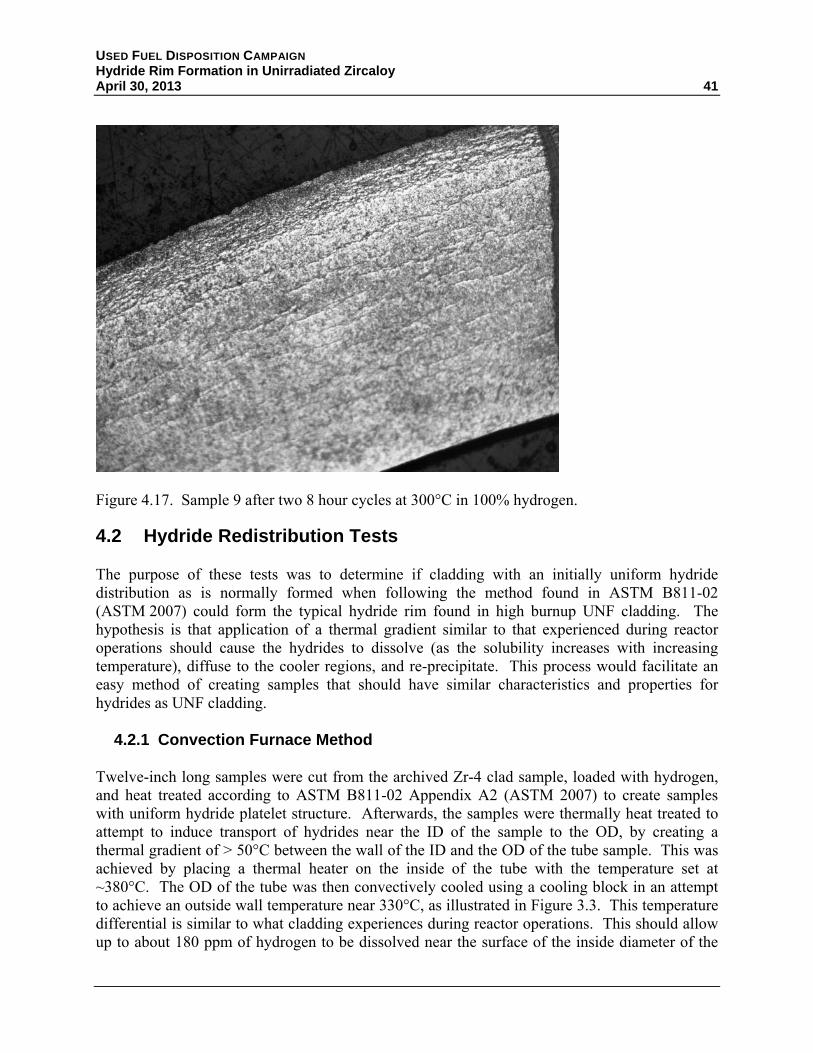
USED FUEL DISPOSITION CAMPAIGN Hydride Rim Formation in Unirradiated Zircaloy April 30, 2013 41
Figure 4.17. Sample 9 after two 8 hour cycles at 300°C in 100% hydrogen.
4.2 Hydride Redistribution Tests
The purpose of these tests was to determine if cladding with an initially uniform hydride distribution as is normally formed when following the method found in ASTM B811-02 (ASTM 2007) could form the typical hydride rim found in high burnup UNF cladding. The hypothesis is that application of a thermal gradient similar to that experienced during reactor operations should cause the hydrides to dissolve (as the solubility increases with increasing temperature), diffuse to the cooler regions, and re-precipitate. This process would facilitate an easy method of creating samples that should have similar characteristics and properties for hydrides as UNF cladding.
4.2.1 Convection Furnace Method
Twelve-inch long samples were cut from the archived Zr-4 clad sample, loaded with hydrogen, and heat treated according to ASTM B811-02 Appendix A2 (ASTM 2007) to create samples with uniform hydride platelet structure. Afterwards, the samples were thermally heat treated to attempt to induce transport of hydrides near the ID of the sample to the OD, by creating a thermal gradient of > 50°C between the wall of the ID and the OD of the tube sample. This was achieved by placing a thermal heater on the inside of the tube with the temperature set at ~380°C. The OD of the tube was then convectively cooled using a cooling block in an attempt to achieve an outside wall temperature near 330°C, as illustrated in Figure 3.3. This temperature differential is similar to what cladding experiences during reactor operations. This should allow up to about 180 ppm of hydrogen to be dissolved near the surface of the inside diameter of the

USED FUEL DISPOSITION CAMPAIGN Hydride Rim Formation in Unirradiated Zircaloy
42 April 30, 2013
cladding sample. If the re-dissolved hydrogen is transported to the outer surface, it should all then precipitate as hydrides, in addition to the hydrides already there, thus forming the desired rim.
All samples used for this study were pre-loaded with hydrogen to approximately 400 ppm H2 by placing the samples in a quartz tube vacuum chamber, enclosed in a small tube furnace. The vacuum chamber was evacuated by turbo pump to ~0.001 torr. The sample was moved into the heated zone of the furnace (500°C). Once the sample was at temperature the valve to the vacuum pump was closed and hydrogen flowed into the chamber for a time determined by the target loading. Loading was confirmed by hydrogen analysis performed by ATI Wah Chang Laboratory Services. Results of actual loading were in reasonable agreement with target values and as loaded metallographic images are shown in Figure 4.18. Thus, about half of the hydrogen near the cladding inner surface should dissolve and potentially be transported to and precipitate at the cooler outer surface.
(a). Outer diameter. As loaded. No heat treatment. Appears to be uniform distribution.
(b). Inner diameter side. As loaded. No heat treatment. Appears to be uniform loading.
Figure 4.18. Metallographic images of the traverse section of pre-loaded samples containing ~400 ppm hydrogen.
A small electrical cartridge heater was then placed inside the cladding and the assembly supported inside a convection furnace (air flow but no heating to provide even air cooling to the outside of the cladding). Samples were heat treated for times ranging from 6 hours up to ~24 hours. Metallography of cross sections of these samples showed little if any hydride concentration gradient with this method. Upon further investigation, it was found that the temperature gradient was less than originally thought (only about 28°C), but was at the limit that could be produced by the convection furnace.
Subsequent attempts to heat treat samples were done by inserting the cartridge heaters into the cladding samples, and placing the assemblies into a larger tube and blowing compressed air over the outside of the cladding samples. This method produced a higher temperature gradient of approximately 55°C, although possibly less uniform temperature over the outer surface.

USED FUEL DISPOSITION CAMPAIGN Hydride Rim Formation in Unirradiated Zircaloy April 30, 2013 43
However, metallography of a cross section (Figure 4.19) did not clearly show the desired hydride gradient. Hydrogen analysis showed no appreciable hydrogen loss to the air during heat treatment.
Figure 4.19. Metallographic examination of sample post thermal treatment.
4.2.2 Autoclave Method
When efforts with the cooling block were not successful, it was believed that by improving control of the OD temperature and extending the testing periods to between 100-200 hours the desired redistribution could be achieved. The testing that followed replaced the OD cooling block with an autoclave that contained saturated steam which maintained the OD at the saturation temperature of the water vapor inside the vessel extremely well and could be adjusted by changing the pressure of the system. Cladding samples were still pre-loaded to 400-500 ppm using the same methods and the same thermal element was used in the ID.
Two tests were performed by this method:
Test1: 100 hours with the OD at 330°C and the ID at 390°C.
Test 2: 100 hours with the OD at 330°C and the ID at 390°C, followed by 100 hours with the OD at 300°C and the ID at 420°C
After each test, the middle section of the tube was subsampled and analyzed for hydrogen gas concentration and examined via metallography. In both cases, the hydrogen concentration was found to be in the expected sample range, but the distribution of hydrides was as before in both cases. Figure 4.20 shows the cross section from the middle of the sample tube from test 2, which
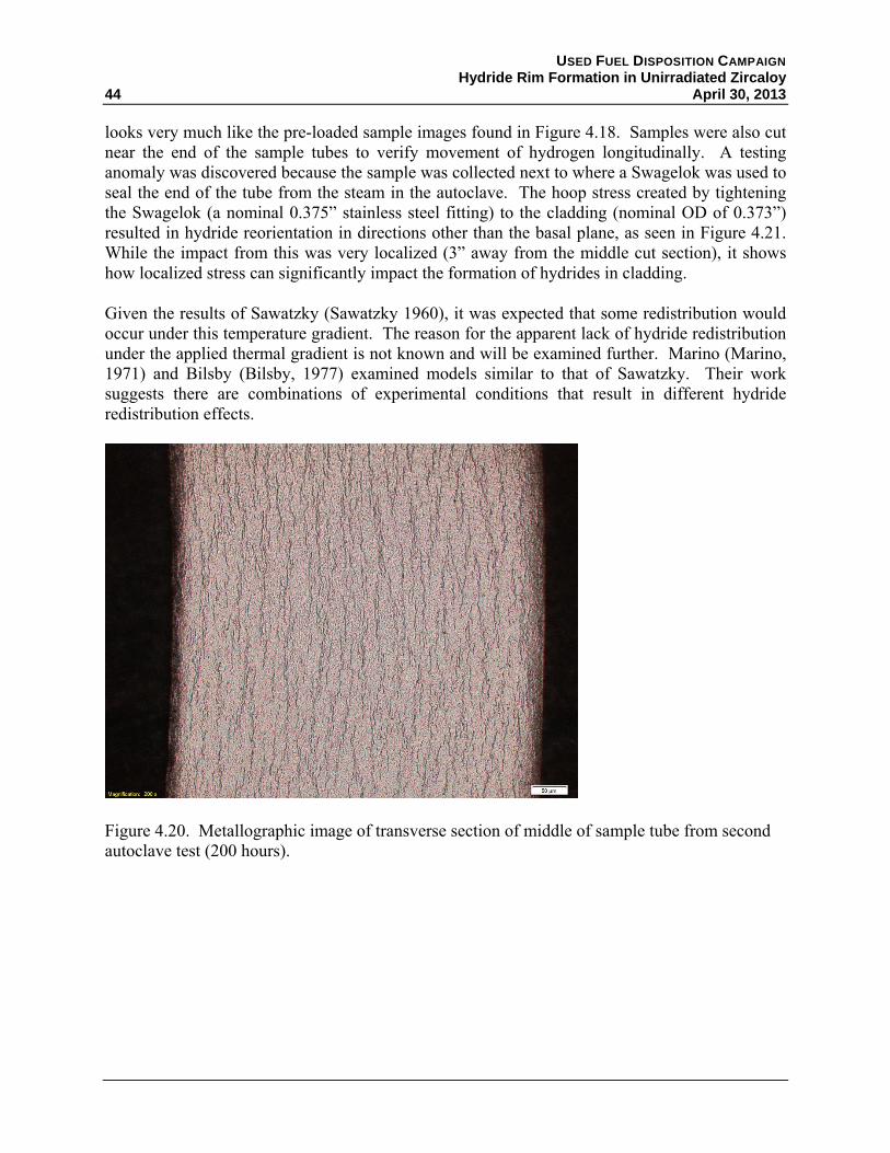
USED FUEL DISPOSITION CAMPAIGN Hydride Rim Formation in Unirradiated Zircaloy
44 April 30, 2013
looks very much like the pre-loaded sample images found in Figure 4.18. Samples were also cut near the end of the sample tubes to verify movement of hydrogen longitudinally. A testing anomaly was discovered because the sample was collected next to where a Swagelok was used to seal the end of the tube from the steam in the autoclave. The hoop stress created by tightening the Swagelok (a nominal 0.375” stainless steel fitting) to the cladding (nominal OD of 0.373”) resulted in hydride reorientation in directions other than the basal plane, as seen in Figure 4.21. While the impact from this was very localized (3” away from the middle cut section), it shows how localized stress can significantly impact the formation of hydrides in cladding.
Given the results of Sawatzky (Sawatzky 1960), it was expected that some redistribution would occur under this temperature gradient. The reason for the apparent lack of hydride redistribution under the applied thermal gradient is not known and will be examined further. Marino (Marino, 1971) and Bilsby (Bilsby, 1977) examined models similar to that of Sawatzky. Their work suggests there are combinations of experimental conditions that result in different hydride redistribution effects.
Figure 4.20. Metallographic image of transverse section of middle of sample tube from second autoclave test (200 hours).
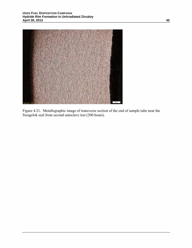
USED FUEL DISPOSITION CAMPAIGN Hydride Rim Formation in Unirradiated Zircaloy April 30, 2013 45
Figure 4.21. Metallographic image of transverse section of the end of sample tube near the Swagelok seal from second autoclave test (200 hours).


USED FUEL DISPOSITION CAMPAIGN Hydride Rim Formation in Unirradiated Zircaloy April 30, 2013 47
5. LESSONS LEARNED AND FUTURE WORK
The purpose of this work is to develop the means of pre-hydriding unirradiated Zircaloy cladding such that a high concentration, or rim, of hydrides is formed at the cladding outside diameter as is found in cladding for high burnup fuels. Samples prepared by this method will then be used in separate effects tests to determine the effect of hydrides and hydride reorientation on the mechanical properties of cladding. Specifically, it is necessary to determine the contribution the lack of hydride rim in the pre-hydrided samples tested by Billone et al. (2008, 2013) had on the ductile-to-brittle transition temperature when compared to irradiated cladding. Results of these tests will also help inform the models being developed for hydride behavior by identifying those parameters of importance.
The initial work performed at PNNL demonstrated that:
It is possible to pre-hydride samples at low temperatures (<400°C) in pure H2
It appears possible to form the desired hydride rim using this technique
Surface conditions of the cladding, and especially the presence or growth of an oxide layer during hydrogen loading, are controlling factors in this process
Hydrogen/hydride redistribution is not as well understood as has been reported in literature.
Work will continue and will examine:
Kinetics and effects of variable H2 gas compositions (i.e., < 100%)
Better control of gas impurities such as oxygen or water vapor either through
- Installation of getters on the gas lines or
- Wrapping samples in high purity Al foil to getter oxygen, as is done by Billone (Billone et al. 2013)
Better control of clad surface conditions either through
- More controlled surface blasting or
- Treatment in HF to thoroughly remove the oxide layer
Better control of important parameters such as local temperature, gas flow rate, and sample cooling rate
Testing of cladding alloys other than just Zr-4 to determine the effect of chemical composition as well as texture on the ability to form the hydride rim
Hydrogen redistribution at the longer times suggested by the model of Sawatzky (Sawatzky 1960).


USED FUEL DISPOSITION CAMPAIGN Hydride Rim Formation in Unirradiated Zircaloy April 30, 2013 49
6. REFERENCES
10 CFR Part 72. Licensing Requirements for the Independent Storage of Spent Nuclear Fuel and High-Level Radioactive Waste. U.S. Nuclear Regulatory Commission, Washington, D.C.
ASTM B349-09. 2009. Standard Specification for Zirconium Sponge and Other Forms of Virgin Metal for Nuclear Application. ASTM International, West Conshohocken, Pennsylvania.
ASTM B811-02. 2007. Standard Specification for Wrought Zirconium Alloy Seamless Tubes for Nuclear Reactor Fuel Cladding. ASTM International, West Conshohocken, Pennsylvania.
Billone M, Y Yan, T Burtseva, and R Daum. 2008. Cladding Embrittlement during Postulated Loss-of-Coolant Accidents. NUREG/CR-6967, U.S. Nuclear Regulatory Commission, Washington, D.C. ML082130389 at http://www.nrc.gov/reading-rm/adams.html.
Billone MC, TA Burtseva, and RE Einziger. 2013. “Ductile-to-brittle transition temperatures for high-burnup cladding alloys exposed to simulated drying-storage conditions.” Journal of Nuclear Materials 433:431-448.
Bilsby, CF. 1977. "A Calculation of the Effect of Supercharging on Hydrogen and Hydride Distribution in a Thermal Gradient in Zircaloy." Journal of Nuclear Materials 68(1):1-8, DOI:http://dx.doi.org/10.1016/0022-3115(77)90209-4.
Bruni G, BJ Lewis, and WT Thompson. 2011. “Framework model for hydrogen redistribution in zircaloy sheathing.” Journal of Nuclear Materials 409(1):33-39.
Chen W, L Wang, and S Lu. 2009. “Influence of Oxide Layer on Hydrogen Desorption from Zirconium Hydride.” Journal of Alloys and Compounds 469(1–2):142-145.
Colas KB. 2012. Fundamental Experiments on Hydride Reorientation in Zircaloy. Ph.D. Dissertation in the Department of Mechanical and Nuclear Engineering, The Pennsylvania State University, University Park, Pennsylvania.
Cox B. 1999. “A mechanism for the hydrogen uptake process in zirconium alloys.” Journal of Nuclear Materials 264(3):283-294.
Hanson B, H Alsaed, C Stockman, D Enos, R Meyer, and K Sorenson. 2012a. Gap Analysis to Support Extended Storage of Used Nuclear Fuel. FCRD-USED-2011-000136 Rev. 0, PNNL-20509, July 31, 2012. Prepared for the U.S. Department of Energy Used Fuel Disposition Campaign, Washington, D.C.

USED FUEL DISPOSITION CAMPAIGN Hydride Rim Formation in Unirradiated Zircaloy
50 April 30, 2013
Hanson B, H Alsaed, and C Stockman. 2012b. Used Nuclear Fuel Storage and Transportation Data Gap Prioritization. FCRD-USED-2012-000109 Draft, PNNL-21360, April 30, 2012. Prepared for the U.S. Department of Energy Used Fuel Disposition Campaign, Washington, D.C.
Hong HS, SJ Kim, and KS Lee. 1998. “Thermotransport of hydrogen in zircaloy-4 and modified zircaloy-4.” Journal of Nuclear Materials 257(1):15-20.
Kammenzind BF, DG Franklin, WJ Duffin, and HR Peters. 1996. “Hydrogen Pickup and Redistribution in Alpha-Annealed Zircaloy-4.” Presented at Conference: 11. international symposium on zirconium in the nuclear industry, Garmisch-Partenkirchen (Germany), 11-14 Sep 1995
Kim YS, and SK Kim. 1999. “Kinetic studies on massive hydriding of commercial zirconium alloy tubing.” Journal of Nuclear Materials 270:147-153.
Marino, GP. 1971. "Hydrogen Supercharging in Zircaloy." Materials Science and Engineering 7(6):335-341, DOI:http://dx.doi.org/10.1016/0025-5416(71)90016-4.
NRC. 2010. Standard Review Plan for Spent Fuel Dry Storage Systems at a General License Facility. NUREG-1536, Rev. 1, U.S. Nuclear Regulatory Commission, Washington, D.C.
Sawatzky A. 1960. “Hydrogen in zircaloy-2: Its distribution and heat of transport.” Journal of Nuclear Materials 2(4):321-328.