appendix e - maine · appendix e-13 driveway drainage strip ... the island can serve the same traf...
TRANSCRIPT

Volume III: BMPs Technical Design Manual Appendix E
Appendix EExample LID Measures
Contents
APPENDIX E-1 Infiltration Dividers
APPENDIX E-2 Infiltration Islands
APPENDIX E-3 Bio-Islands & Bio-Cells
APPENDIX E-4 Grassed Infiltration Strips
APPENDIX E-5 Dry Stream Infiltration Bed
APPENDIX E-6 Alley Infiltration
APPENDIX E-7 Decorative Planters
APPENDIX E-8 Curbside Treatment
APPENDIX E-9 Dry Wells
APPENDIX E-10 Pocket Raingarden
APPENDIX E-11 Raingarden Planter
APPENDIX E-12 Raingarden Strip
APPENDIX E-13 Driveway Drainage Strip
APPENDIX E-14 Containment Swale
Volume III: BMPs Technical Design Manual
Page E-2
Appendix E
Appendix E-1: Infiltration Divider
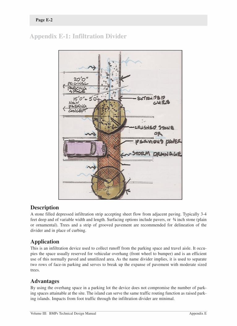
DescriptionA stone filled depressed infiltration strip accepting sheet flow from adjacent paving. Typically 3-4
feet deep and of variable width and length. Surfacing options include pavers, or ¾ inch stone (plain
or ornamental). Trees and a strip of grooved pavement are recommended for delineation of the
divider and in place of curbing.
ApplicationThis is an infiltration device used to collect runoff from the parking space and travel aisle. It occu-
pies the space usually reserved for vehicular overhang (front wheel to bumper) and is an efficient
use of this normally paved and unutilized area. As the name divider implies, it is used to separate
two rows of face-in parking and serves to break up the expanse of pavement with moderate sized
trees.
AdvantagesBy using the overhang space in a parking lot the device does not compromise the number of park-
ing spaces attainable at the site. The island can serve the same traffic routing function as raised park-
ing islands. Impacts from foot traffic through the infiltration divider are minimal.

Volume III: BMPs Technical Design Manual
Page E-3
Cost is mainly affected by surface treatment. The plain stone surface treatment is not as costly and
performs as well as the more expensive pavers which can be used by those who wish to add more
distinction and aesthetic appeal to their parking lot.
DisadvantagesPlanting choices may be limited by drought tolerance and width of island (shrubs may be too wide
at the car bumper level and become deformed/injured).
The low organic content within the island unit may not provide optimal treatment of organic pollu-
tants if it is located in rapidly draining sandy soils. Some augmentation with coarse peat at the bot-
tom of the stone reservoir (6" thick) area may be warranted in these cases.
Design ConsiderationsDesigns are optimized at 8-10 feet in width which is the normal distance between front axles of vehi-
cles parked nose to nose. The divider handles runoff from the centerline of a typical 20 foot wide
travel aisle and the 15 foot parking space. This width also protects trees and cars from butting up to
each other. When used as a true divider to separate two rows of parking, widths should not be less
than 6 feet.
Depths can vary, but the floor of the structure should be at least two feet from the seasonal high
water table. Depths from the inlet surface elevation to the floor of the structure of 2 feet or less are
only appropriate if infiltrating the first ½-inch of runoff.
A deeper surface depression can maximize the volume retained within the structure as no stone occu-
pies this space and all of it can be used for retention. Curbing or wheel stops could be used in this
application to prevent cars from entering the depression. In some cases, curbing would prevent an
even distribution of water to the surface of the structure and the gaps between wheel stops may
become blocked and glazed over from snow plowing operations. Alternately, grooves should be cut
in the pavement 6" from the edge, around the perimeter of the structure. The grooves will provide a
reasonable assurance that cars will come to a stop as they pull forward in the parking space and will
provide no restriction for water entering the structure.
Surface treatment materials must be highly porous and durable. They can range from ¾ inch stone
(ornamental or plain) to pervious pavers. Cost will play a large part in the choice of surface materi-
als since pavers are more expensive than stone.
Treatment of stormwater in this device is accomplished by the stormwater passing first though the
filter fabric and then through the native soil surrounding the main chamber. The main distinction of
the Infiltration Divider is its ability to rapidly accept stormwater below grade. Organic material and
the associated decomposition matter can hinder the ability of the surface to accept runoff.
Shade trees are recommended, to assist in delineating the Infiltration Divider from the traveled por-
tions of the parking lot. This RPM offers a balance between rapid infiltration and aesthetic and traf-
fic control objectives.
Appendix E

Volume III: BMPs Technical Design Manual
Page E-4
Appendix E
MaintenanceThe frequency of surface rehabilitation can vary from 1-5+ years based on sand application rates and
sweeping of the parking lot. Rehabilitation involves use of a vacuum truck or manual labor to
remove the top 6 inches of material and replacement of the filter fabric pre-filter zone. Although
stone may be screened from the accumulated sand and sediment and reused, it may be more practi-
cal and cost effective to send the removed material to a gravel facility for reprocessing and replace
it with a new 6 inch stone layer after each cleaning.

Volume III: BMPs Technical Design Manual
Page E-5
DescriptionA medium sized surface infiltration structure with a durable surface that can withstand occasional
vehicle traffic. Plantings are sparse and infiltration capacity at the surface is high.
ApplicationThese islands are meant to be used in parking lots at the end of parking rows or in areas where vehi-
cles and pedestrians are likely to cut corners. The limited low-growing vegetation aids in providing
sufficient line of sight for vehicular turning movements. Durable surface elements provide pedestri-
ans space while waiting to cross from the parking lot to building entrance.
AdvantagesDurable with the use of pavers so that it can withstand occasional traffic with little to no damage.
Selection and variation of colors and style of pavers can help delineate parking for one store vs.
another in a large parking lot.
Clear line of site for vehicle turning movements and pedestrian crossing.
With slight modifications to flatten side slopes, islands may provide additional adjacent space for
access in and out of vehicles by handicapped persons.
DisadvantagesPlanting choices may be limited by line of sight considerations and drought tolerance.
Pavers are more costly than a simple crushed stone surfacing.
Appendix E
Appendix E-2: Infiltration Islands

Volume III: BMPs Technical Design Manual
Page E-6
Design ConsiderationsAlthough compaction of material is generally discouraged with RPMs, it may be warranted in the
areas likely to be trafficked by vehicles.
If used at the downgradient end of a row of parking spaces and attached to another RPM such as the
Infiltration Divider, the design should be graded such that each RPM provides the maximum amount
of storage and infiltration. If both RPMs are sloped in one direction, placing one RPM downgradi-
ent from the other, the downgradient RPM could become overwhelmed with water, leading to fre-
quent use of the overflow and underutilization of the available storage space in the upgradient struc-
ture.
The low organic content within the structure may not provide optimal treatment of organic pollutants
if the structure is sited in rapidly draining sandy soils. Some augmentation with coarse peat at the
bottom of the stone reservoir (6" thick) area may be warranted in these cases.
MaintenancePaver surfaces located in traffic areas will require periodic inspection for deflection (raised or
uneven surfaces) to ensure that they will not be pulled up during winter plowing activities. This is
best inspected in the Fall, before snowfall. If deflection approaches half of the paver thickness, the
affected paver(s) will need to be re-leveled flush to the others.
Sand deposits that have accumulated on the surface of the RPM will need to be removed periodical-
ly. A wet/dry vacuum is ideal for this and will prolong the life expectancy of the surface of the struc-
ture before the pavers, bedding material, and filter fabric must be completely removed and replaced
and/or reassembled. The use of a push broom to remove deposits may be quicker in the short run,
however may result in redistribution of much of the accumulated sediments and debris over the sur-
face. If sediment removal maintenance is not conducted, the surface may require rehabilitation on a
more frequent basis.
It is advisable to occasionally monitor the RPM during a rainstorm to determine if "preferential flow
paths" have developed and/or if water seems to make its way to the overflow before using up the
capacity of the reservoir/depression area. Forty-eight hours after the storm has stopped1 the reser-
voir/depression area should have completely drained. Surface ponding conditions that exceed 48
hours are undesirable as nuisance conditions can develop soon thereafter. Prolonged surface pond-
ing (over 48 hours) indicates that the surface area needs to be rehabilitated by removing and clean-
ing or replacing the surface material down to and including the first filter fabric barrier encountered.
An observation well can be installed in the structure to determine whether the infiltration media
below the filter fabric has clogged.
Appendix E
1This is a storm of normal duration during the growing season and would not include prolonged periods of rainfall, or
spring thaw conditions for example.

Volume III: BMPs Technical Design Manual Appendix E
Page E-7
Appendix E-3: Bio-Islands & Bio-Cells
DescriptionAn installation of varying proportions (Bio-Cell being small to medium in size and Bio-Island being
a larger more centralized treatment and landscaping feature) that may be designed to support a wide
variety of plantings and provides a beneficial "habitat" for pollutant removal.
ApplicationOther than scale, both Bio-RPMs may be used at a variety of sites. Their high organic component
means that it can be used as a landscape focal point in a prominent location on the site, however
infiltration rates may be compromised for the same reason. These systems (particularly the smaller
Bio-cell) are better adapted to handling drainage from smaller, flatter, less "flashy" drainage areas.
AdvantagesThese systems provide a more complete habitat for beneficial microorganisms and thus excellent
stormwater treatment can be expected. The high organic content and free form nature of the Bio-
Island lends it to a wealth of colors and textures in the plantings. Separate planting zones within
these structures can be created to support plants of complementing treatment efficiency and appear-
ance.

Volume III: BMPs Technical Design Manual
Page E-8
Appendix E
DisadvantagesThe trade off for having a higher organic content with greater planting choices is that the ability of
the device to accept and quickly infiltrate water may be compromised.
Design ConsiderationsCare must be taken in estimating the proper storage volume within the reservoir area. Different
blends of planting media (which occupy a substantial portion of the subsurface area) will yield con-
siderably different available storage space.
When bark mulch is used for the surfacing material, fresh mulch is preferable to aged for nutrient
assimilation. If shredded wood chips are used as a substitute, hardwood varieties are known to be
less likely to float when the structure has surface ponding.
In the larger Bio-Island application, designers should note that two treatment areas are intended. The
outer layer is meant to settle out and assimilate reasonable amounts of sand and the coarse grass is
meant to act as a living leaf/debris rack. This enables the inner area to receive water that is relative-
ly free of debris and particulates, and thus preserves the surface infiltration rate and prolongs the
time needed between clean up.
MaintenanceThe leaves that fall onto the surface of these structures can quickly form a surface barrier to incom-
ing water and so a Spring and Fall clean-up is recommended. The higher maintenance frequency in
these structures relative to other RPMs is a function of their landscaping requirements. Owners want
these structures well maintained to preserve and support their planting investment for a number of
years.

Volume III: BMPs Technical Design Manual
Page E-9
Appendix E
DescriptionA grassed area located at the edge of pavement to filter contaminants by flowing through vegetation
and through infiltration. A typical strip size is 10 feet wide with a minimum depth of 6 inches to
allow for temporary ponding of water. Grassed Infiltration Strips are aesthetically pleasing and per-
form a similar function to filter strips along a river.
ApplicationThis infiltration device is used primarily for filtering overland stormwater flow from an impervious
surface. It also incorporates infiltration into its treatment mechanism. It is ideally used when there
is sufficient space around a parking lot or impervious drive.
AdvantagesGrass is easily mowed and therefore is a low maintenance surfacing. The area used for this device
is typically unused space around parking lots or along the edge of a road and can therefore easily
conform to this treatment option. It has a sufficient storage capacity even though it is easily mistak-
en for a normal lawn. Occasional nonvehicular traffic is permitted by the surfacing.
DisadvantagesInfiltration rates through the planting media may not be as rapid as through other surfacing options.
Should not be used in areas where perimeters of parking lots and drives slope towards the parking
lot or drive, unless an overflow device is implemented.
Design ConsiderationsParking lots and drives with perimeters sloping into them are not feasible for this device. Water must
be able to flow across the device and away from the parking lot. Runoff flows with high concentra-
tions of sediment will cause the depression to fill in. This will necessitate frequent maintenance for
Appendix E-4: Grassed Infiltration Strips

Volume III: BMPs Technical Design Manual
Page E-10
the strip and should be avoided. These strips should be located where they are not frequently crossed
or a small walking bridge could be placed to allow crossing after periods of high rainfall. The down-
hill side of the crushed stone area should be a minimum of 6 feet from any steep slopes.
High traffic areas should be avoided because of compaction and the potential for water to pond in
the depression. If many people were to walk over the strip, the infiltration capacity will be greatly
reduced. This compaction could also kill the vegetation and destroy the overall treatment effective-
ness of the RPM.
MaintenanceThe grass is a low maintenance surface which should be maintained at typical height. Occasional
high flows may carry a lot of sediment into the depression. Upon removal of this sediment care must
be taken to not dig up the current vegetative layer. The 1 foot planting media filter layer and the fil-
ter fabric will prevent silt from entering the crushed stone. When infiltration rates are greatly
reduced from this silt, the planting media may be removed along with the filter fabric and new mate-
rials put in place. Maintenance costs are relatively cheap until the filter layer is excavated.
Appendix E

Volume III: BMPs Technical Design Manual Appendix E
Page E-11
DescriptionA large structure designed to contain and infiltrate large volumes of stormwater. A dry riverbed
theme has been chosen, and certain landscape elements added (boulders, etc.) to showcase what
might otherwise be a large stark infiltration strip. Other elements such as ornamental bridges and
picnic tables allow the area to be used as an informal outdoor lunch area during good weather.
ApplicationThis RPM is intended to handle large volumes and rates of stormwater typical of a commercial park-
ing lot. Providing a picnic area can make the installation have even greater utility on the typical
tightly constrained office parking lot.
AdvantagesThis RPM has the ability to handle large volumes of stormwater. The "themeing" of the structure can
allow it to be used as an amenity and add character which may differentiate the property from oth-
ers. Perhaps a good selling point to prospective buyers.
DisadvantagesThe limited use of vegetation will provide little shade or cooling effects to the parking lot as a whole.
As a large centralized device, this structure provides a greater vehicle restriction. The abundance of
ornamental features (such as boulders and picnic tables) can add cost with no gain in capacity.
Appendix E-5: Dry Stream Infiltration Bed

Volume III: BMPs Technical Design Manual
Page E-12
Appendix E
Design ConsiderationsVolume calculations should account for ornamental features that are proposed to be located below
the invert of the overflow.
When bark mulch is used for the surfacing material, fresh mulch is preferable to aged for nutrient
assimilation. If shredded wood chips are used as a substitute, hardwood varieties are known to be
less likely to float when the structure has surface ponding.
Because of its size, a significant slope throughout the length of the structure (when installed paral-
lel to the slope) can cause ponding, and associated overflows at the downgradient end and underuti-
lized storage volume at the upper end. Installing the structure perpendicular to the slope is the pre-
ferred orientation, but in cases where it must be installed parallel, impervious walls should be
installed down to the floor of the leaching area. These barriers serve as grade checks and should
extend through the surface (and perhaps hidden by a footbridge) with sufficient reveal to compart-
mentalize the structure so that lateral movement is minimized.
If picnic tables and other pedestrian attractive features are used, localized compaction may occur
resulting in less stormwater infiltration in these areas. Stepping stone walkways or seating areas can
be added and are one way to concentrate use within the structure. These impervious features should
always be surrounded by pervious materials.
MaintenanceBecause the mulched areas serve as pretreatment zones they must be managed as such. The mulched
planting area will require periodic inspection for sediment buildup. Sediments collected in specific
areas that are not retained by the planting bed will require periodic removal. The RPM should also
be inspected occasionally during a storm event to ensure that the RPM is not short-circuiting (creat-
ing preferential flow paths for the runoff) which minimizes the pretreatment effects of the mulched
planting area.

Volume III: BMPs Technical Design Manual Appendix E
Page E-13
Appendix E-6: Alley Infiltration
DescriptionA surface infiltration area with a narrow entrance comprised of a durable surfacing such as cobble
stones or pavers. No vegetation is used in this structure.
ApplicationAlley Infiltration is meant to be used in narrow areas where vehicular traffic is concentrated. Areas
with roof leaders that discharge to a paved surface may also be served by these installations.
Designers who wish to disconnect roof leaders from a current underground storm drain connection
and allow them to discharge to a paved surface (for entrance into the Alley Infiltration) should con-
sider safety issues that may arise in winter due to icing.
AdvantagesAt sites with little or no existing access to the underlying soil, these installations allow for stormwa-
ter infiltration with no loss in serviceability of the area.
DisadvantagesSurfacing the Alley Infiltration structure with a durable material such as pavers or cobblestones can
comprise a significant portion of the cost of the installation.

Volume III: BMPs Technical Design Manual
Page E-14
Appendix E
Proximity to foundations may necessitate underdrains and/or installation of impervious barriers that
may affect the level of groundwater recharge.
Design ConsiderationsIf Alley Infiltration is used in service entrances, areas where heavy vehicles are likely to be turning
and tracking across the pervious surface, or any other traffic patterns where the vehicles don't strad-
dle the pervious surface, designers provide structural support (more compaction of subgrade and
bedding materials) while maintaining sufficient surface infiltration rates.
If foundations or other subsurface structural features are located nearby (within 10') or downgradi-
ent of the Alley Infiltration, advice from a geotechnical engineer should be sought.
The low organic content within Alley Infiltration may not provide optimal treatment of organic pol-
lutants if the structure is sited in rapidly draining sandy soils. Some augmentation with coarse peat
at the bottom of the stone reservoir (6" thick) area may be warranted in these cases.
MaintenancePaver/cobblestone surfaces located in traffic areas will require periodic inspection for deflection
(raised or uneven surfaces) to ensure that they will not be pulled up during winter plowing activi-
ties. This is best inspected in the Fall, before snowfall. If deflection approaches half of the
paver/cobblestone thickness, the affected paver(s)/cobblestone(s) will need to be re-leveled flush to
the others.
Sand deposits that have accumulated on the surface of the RPM will need to be removed periodical-
ly. A wet/dry vacuum is ideal for this and will prolong the life expectancy of the surface of the struc-
ture before the pavers, bedding material, and filter fabric must be completely removed and replaced
and/or reassembled. The use of a push broom to remove deposits may be quicker in the short run,
however may result in redistribution of much of the accumulated sediments and debris over the sur-
face. If sediment removal maintenance is not conducted, the surface may require rehabilitation on a
more frequent basis.

Volume III: BMPs Technical Design Manual
Page E-15
Appendix E
Appendix E-7: Decorative Planters
DescriptionA self-contained upright structure that provides stormwater treatment and attenuation, but usually
little groundwater recharge. With similarities to window box planters or raised planting beds, these
designs are very ornamental.
ApplicationThe Planters are designed to capture and treat stormwater originating from rooftops, by intercepting
water from roof leaders prior to it entering an existing underground piped drainage system.
Advantages
For sidewalks and other areas with constricted spaces, the planters can be designed to be narrow, and
yet still perform well and look attractive.
The generous volume of planting media used in these designs should allow for a wide variety of
annuals to thrive.
DisadvantagesPlanters are not designed to provide recharge to groundwater.
Because the Planters must be disconnected in Winter (downspouts must be disconnected from the
planters and redirected to their original point of discharge), the volume of water treated annually is
less than that of other RPMs that receive at least a portion of meltwater during freeze thaw condi-
tions of late Fall and early Spring.

Volume III: BMPs Technical Design Manual
Page E-16
Design ConsiderationsDepending on space constraints, the planters can be tall and flush with a wall as might be the case
with an installation on a sidewalk, or they can be shorter and wider making it similar to a raised
planting bed.
Designers and owners should understand that during the Winter the Planters will be exposed to the
elements and therefore may not be conducive to the survival of perennial flowers. For this reason,
the beds will need to be planted annually, and thus annuals with their vibrant colors may be a good
choice.
Weep holes should be provided at the lowest point in the structure to allow the system to drain
between storms. The weeps could drain to the overflow pipe and thus back into an existing under-
ground drainage system. This would be desirable if the planters are located on a sidewalk so that
water does not flow across the sidewalk. If the planters are to be located on a pervious surface the
weeps can drain directly to the ground, however foundation concerns (see discussion in Design
Constraints Section) may need to be addressed.
Designers may want to install an access port on the side of the planters. This would allow access to
the end of the perforated pipe for cleaning out debris and roots every couple of years.
MaintenanceMaintenance for the Planters is similar to that of normal flower beds, however the application of sol-
uble fertilizer is discouraged. Those maintaining the plants and flowers should be careful not to over-
ly compact the planting media and prevent percolation.
Appendix E

Volume III: BMPs Technical Design Manual
Page E-17
Appendix E
Appendix E-8: Curbside Treatment
DescriptionCurbside treatment has been developed to meet the stormwater management needs of downtown
streets and sidewalks where pervious surfaces do not exist. The RPM involves the construction of a
pervious sidewalk underlain by a perforated drain pipe. Runoff generated from the sidewalk can per-
colate through the pervious materials into the underdrain system, while runoff from the roadside can
be collected in a catch basin and connected to the underdrain below ground. Normal difficulties
relating to access for maintenance or replacement have been reduced in the design through the use
of pretreatment devices and removable surfaces.
ApplicationCurbside treatment is meant to be used to treat runoff from sidewalks and curbed streets where few
onsite options exist.
AdvantagesUsing cobblestones or pavers in place of concrete for sidewalks allows any runoff from the sidewalk
to percolate into the ground. This treatment can add beauty and distinction to the streetscape. Most
important from a maintenance/longevity standpoint, the removable (non-grouted) surface allows for
easier access to the perforated pipe for cleaning or eventual replacement when it reaches the end of
its service life.

Volume III: BMPs Technical Design Manual
Page E-18
Appendix E
DisadvantagesPretreatment provided in the upgradient diversion catchbasin will not be as effective as most RPMs
with pretreatment occurring at the surface and will be dependent upon frequency of catch basin
cleaning operations.
Conflicts with underground utilities may limit the use of curbside treatment in some areas.
Design ConsiderationsPretreatment of the roadway runoff is provided in a new upstream catchbasin. To enhance the
removal rate of particles, trash and floatables, a hooded outlet cover may be installed. The sump in
the catchbasin should be as deep as is practical to further enhance settling.
A variety of pervious surfacing choices exist for use in this design since the runoff from most side-
walks can be captured and infiltrated sufficiently even with a brick (ungrouted) sidewalk. In areas
where sidewalks are plowed, designers should confer with local personnel on this matter and utilize
surfacing options that do not hinder these operations.
MaintenanceThe long-term operation of Curbside Treatment relies heavily upon the removal of particles in the
new upgradient diversion catchbasin. To this end, a commitment must be made to clean catchbasins
before they are filled with sediment to the outlet invert. A good rule of thumb is to clean the catch-
basin when the level of accumulated sediment is within 18" of the outlet invert.

Volume III: BMPs Technical Design Manual
Page E-19
Appendix E
Appendix E-9: Drywells
DescriptionDrywells are underground areas that have been excavated and filled with stone. The voids between
the stone are where stormwater is stored until it can be leached to the underlying native soils. The
greatest benefit of using drywells is to remove roof runoff from the flowstream, and to recharge
groundwater. This preserves the capacity of other RPMs to address runoff from other sources that
may contain higher pollutant loads.
ApplicationDrywells have been used for a variety of purposes, usually as a passive drain for foundations, or to
receive periodic discharges from sump pumps. More recently, drywells have been used to accept
roof runoff. The drywells presented here are mainly used to accept roof runoff, which typically is
free of most material that would otherwise clog a system.
Sizes of drywells can range from small installations that handle under 100 gallons in small light-
weight plastic chambers, to very large installations using preformed concrete leaching chambers.
AdvantagesDrywells are simple structures that are typically inexpensive to install and with the variety of prod-
ucts available to construct them, many homeowners will find installation within their capabilities.
Drywells can be fully hidden from view. Because there are few above ground features, maintenance
is minimal.
Drywells may be installed deep enough (below the frost line) that they would continue to infiltrate
meltwater from roofs during the freeze thaw cycles that occur in late Fall and early Spring.

Volume III: BMPs Technical Design Manual
Page E-20
Appendix E
DisadvantagesInstallations near foundations can cause leaky basements.
Design ConsiderationsDrywells have been historically used to capture water from one area and disperse it over another,
however the drywells presented in this manual have a number of features that address weaknesses
inherent in some of the past designs.
The improved drywells presented in this document utilize filter fabric to preserve the capacity of the
leaching structure and stone reservoir. Early drywells were just stone filled pits with no protection
against slumping and migration of the surrounding soil into the void spaces. A gradual reduction in
capacity resulted. Small sinkholes or areas where the earth has settled are usually an indication that
the drywell has failed. The use of non-woven filter fabric to completely encapsulate the stone reser-
voir area will prevent both of these conditions. The common practice of using straw as a pervious
separation barrier is discouraged since over time is can consolidate and form a semi-pervious layer.
Cleanouts should be installed wherever acute bends in the pipe occur. One cleanout/observation port
should be provided directly into the main leaching area so that the interior can be inspected without
disturbing the ground surface over the Drywell. This port can be designed to serve as an overflow
for large storms, so that once the capacity of the drywell has been used up water will just overflow
to the ground.
Because leaves could quickly "seal" off the interior of a drywell, some form of gutter screen should
be installed for all gutters contributing stormwater to the drywell.
MaintenanceMaintenance for drywells is mainly preventative. Gutter screens should be cleaned as needed and
drywells should be inspected through the observation port occasionally to ensure that they are drain-
ing completely within 3 days of the end of a storm.
In larger Drywells, manways are usually a standard component in the concrete leaching chamber.
The location of these manways should be noted on plans or as-builts so that once buried, they can
be found later and used to provide access for cleaning the inside of the structure.

Volume III: BMPs Technical Design Manual
Page E-21
Appendix E
Appendix E-10: Pocket Raingarden
DescriptionA small surface fed infiltration device used to decorate driveway entrances and receive driveway
runoff. Pocket Raingardens are modeled after planting beds commonly found in residential settings.
ApplicationAlthough Pocket Raingardens can be used on larger commercial properties, they are best suited to
residential application. On a commercial property the amount and rate of runoff generated on these
substantial impervious areas would quickly overwhelm them, and so other RPMs are usually chosen
for their higher infiltrative surfaces. On a residential property, a number of Pocket Raingardens are
typically installed on a site for proper landscaping balance and due to their small size and capacity.
AdvantagesThe generous volume of planting media used in these designs should allow for a wide variety of
plants and shrubs to survive. The presence of organic material provides a habitat for beneficial
organisms that break down NPS pollutants.
DisadvantagesThe relatively thick layer of planting media that supports plant growth will tend to have a lower infil-
tration rate than other more porous surfacing options such as stone. This is generally not a problem
for residential applications if the contributing drainage area is not excessive.
Design ConsiderationsDesigners and installers of Pocket Raingardens should be careful not to let the surface ponding depth
exceed 8 inches, or let the water stay on the surface for more that 48 hours as nuisance conditions

Volume III: BMPs Technical Design Manual
Page E-22
Appendix E
can develop in 3 to 4 days. The installation of an underdrain may be helpful in promoting shorter
drain times if these conditions are anticipated and cannot be avoided. Remember however, that true
groundwater recharge will not be provided if the underdrain discharges to a nearby municipal storm
drain.
To aid in the degradation of certain NPS pollutants such as nitrogen, designers may want to consid-
er adding an impervious liner under the leaching area of a Pocket Raingarden (if an underdrain is
also provided). The liner should be placed 8-18" inches below the invert of the underdrain pipe so
that water that pools in this pocket stays there for a sufficient time to become anoxic and promote
denitrification. Underdrain discharge points should be located far enough away from living areas so
that the "earthy" smell that sometimes develops under these conditions does not bother the home-
owners.
MaintenanceThe Pocket Raingarden is vulnerable to compaction and homeowners need to be aware of this when
performing the simple maintenance that this RPM requires. Because all stormwater must pass
through the thick layer of planting media, compaction within it will limit its overall capacity and can
increase the period of time that water is ponded on its surface. To lessen compaction associated with
foot traffic or maintenance activities, a bark mulch surfacing over the planting media is recommend-
ed. Additionally, homeowners should be discouraged from using fungicides or other persistent pes-
ticides in or around Pocket Raingardens because, in addition to killing the undesirable targets, other
organisms that aerate the soil (worms, ants etc.) may be killed. If this principle of preserving the
infiltration rate is observed, the maintenance of a Pocket Raingarden is no different from any other
conventional planting bed.

Volume III: BMPs Technical Design Manual
Page E-23
Appendix E
Appendix E-11: Raingarden Planter
DescriptionA small surface fed infiltration device used to decorate driveway entrances and receive driveway
runoff. Raingarden Planters are similar to conventional planting beds found in residential settings,
however they have a crushed stone edging along their downgradient side which serves as a conduit
to the stone infiltration reservoir, once the organic planting media has become saturated.
ApplicationRaingarden Planters can be used on commercial or residential properties. A number of Raingarden
Planters are typically installed on a site for proper landscaping balance and due to their smaller size
and capacity.
AdvantagesThe depth of planting media used in these designs should allow for a wide variety of plants and
shrubs to survive.
The presence of organic material provides a habitat for beneficial organisms that break down NPS
pollutants.
The lack of filter fabric over the surface of the planting area makes cleaning easier since care is not
needed to prevent tearing of the filter fabric.
Volume III: BMPs Technical Design Manual
Page E-24
Appendix E
DisadvantagesBecause there is no filter fabric pre-filter in the planting design, more material within the structure
may require removal to ensure all of the clogging media has been removed.
Design ConsiderationsRaingarden Planters do not utilize a filter fabric pre-filter which means that the structure's overall
design life will be shorter, however the frequency of and type of maintenance will be far less than
other stormwater treatment devices, and mainly involve replacing the mulch.
Designers and installers of Raingarden Planters should be careful not to let the water stay on the sur-
face for more than 48 hours after a rain event1 as nuisance conditions can develop in 3 to 4 days.
MaintenanceThe Raingarden Planter is vulnerable to compaction and so homeowners need to be aware of this
when performing the simple maintenance that this RPM requires. Maintenance will involve the peri-
odic removal of sediments from the surface. The duration for the system to drain can be used as an
indicator of when the system has clogged.
Homeowners should be discouraged from using fungicides or other persistent pesticides in or around
Raingarden Planters because, in addition to killing the undesirable targets, other organisms that aer-
ate the soil (worms, ants etc.) may be killed.
1This is a storm of normal duration during the growing season and would not include prolonged periods of rainfall, or
spring thaw conditions for example.

Volume III: BMPs Technical Design Manual
Page E-25
Appendix E
Appendix E-12: Raingarden Strip
DescriptionA Raingarden strip is a redesigned hedgerow or garden border that has an enhanced ability to inter-
cept and infiltrate stormwater runoff from residential streets, driveways and sheet flow from adja-
cent lawn areas, if needed.
ApplicationRaingarden strips can be used in either a commercial or residential setting with the appropriate mod-
ifications to the scale of the structure.
Because of the linear shape of these designs, locating them downgradient of other smaller RPMs can
provide a backup or duplicity of treatment on sites where this is desirable. For instance, if because
of space constraints, an undersized drywell is installed, it may overflow during moderate storms. The
excess water may then flow across a lawn picking up fertilizer residues and other NPS pollutants.
These would be captured however, by the Raingarden strip that is located downgradient at the edge
of the lawn.
AdvantagesThe generous volume of planting media used in these designs should allow for a wide variety of
plants and shrubs to survive.

Volume III: BMPs Technical Design Manual
Page E-26
Appendix E
The presence of organic material provides a habitat for beneficial organisms that break down NPS
pollutants.
DisadvantagesThe appearance and orientation of this RPM may limit its landscaping appeal as people have differ-
ent landscaping taste and needs. These RPMs are intended to be located in close proximity to a drive-
way or street and may look awkward placed in the middle of a lawn.
Design ConsiderationsWhen located to receive runoff from streets or large driveways some stabilized surface is needed
where the stormwater enters the Raingarden Strip. This can be stone or some other durable material
that is not likely to be moved by the force of the water entering the Strip in this concentrated loca-
tion.
Care must be taken when designing the Raingarden Strip to ensure that the planting media is not so
isolated from the incoming flow that only large storms that fill the structure are able to moisten the
planting media and roots. This is obviously less of a concern if drought tolerant plantings have been
selected. For installations where sheet flow will comprise a major portion of the contributing
stormwater, the planting media should extend to the upgradient edge of the Strip with the stone on
the downgradient side. This lets the stormwater contact the media first and when it can no longer
absorb moisture the flow continues across to the stone surface that provides a conduit to the stone
reservoir area underneath.
MaintenanceIf a stabilized entrance is provided, maintenance activities will include removal of surficial sediment
deposits and replacing/raking stone that has been moved during large storms.
The bark mulch that covers the planting media should be replaced as needed.
If stormwater ponds on the surface of the structure for longer than 48 hours after the end of a storm1,
the filter fabric pre-filter may be clogged. In this case, the filter fabric and material covering the
upper most layer of filter fabric should be removed. Owners may then either replace both the filter
fabric and the cover material or, alternatively, clean the clogging material from them and reuse them.
This material should not need to be disposed of at a landfill, however it should not be placed on an
area that will be subject to runoff which might resuspend it.
The frequency of this rehabilitation will depend on the ratio of filter fabric surface to contributing
drainage area, the amount of sand applied to the impervious drainage area, and the frequency with
which preventative maintenance has been performed.
1This is a storm of normal duration during the growing season and would not include prolonged periods of rainfall, or
spring thaw conditions for example.

Volume III: BMPs Technical Design Manual
Page E-27
Appendix E
Appendix E-13: Driveway Drainage Strip
DescriptionThis consists of an infiltration trench located in a driveway, and oriented perpendicular to the direc-
tion of travel. This RPM may be driven on and accepts stormwater runoff from driveways with low
volumes of traffic (such as residential).
ApplicationThis RPM is suited to residential drives or those with very low volumes of traffic with uniform vehi-
cles types.
AdvantagesThese RPMs are very inexpensive to construct and can be used to delineate parking from travel areas
or add some definition between shared drives.
DisadvantagesIf the driveway is plowed in the winter, the operator should be made aware of the Strip so that they
do not disrupt the surfacing materials.
Design ConsiderationsIn driveways where there is a high degree of crown or cross-slope, a Driveway Drainage Strip may
subject the adjacent pavement to abuse from plows. As with most plowing obstacles, prior scouting
of the site (before it snows) by the plow operator and sufficient markings (reflectors or similar
object) can alleviate most potential problems

Volume III: BMPs Technical Design Manual
Page E-28
Appendix E
MaintenanceWhen stormwater no longer collects and infiltrates in the Strip or sediment can be seen occupying
the void space of the stone, the stone and sediment must be removed and replaced.
If the pavers or other tracking material is protruding by more that half of its thickness, the bedding
material should be re-leveled and the pavers re-layed to create a level surface with the surrounding
pavers and pavement.

Volume III: BMPs Technical Design Manual
Page E-29
Appendix E
Appendix E-14: Containment Swale
DescriptionA shallow depression located adjacent to a roadways shoulder that is used to capture and infiltrate
roadway runoff and/or lawn runoff before it enters a catchbasin. Although similar to a typical swale,
this RPM is designed to pond and infiltrate water to the maximum extent possible, rather than as a
means of conveyance. Excess water overflows into a nearby catch basin.
ApplicationThere are two applications for this design. The first would be to collect roadway runoff from a street
without an existing curb and gutter system. The RPM is constructed along the edge of the street
allowing runoff to enter into it before discharging to a downgradient catch basin. The second appli-
cation is to collect runoff from lawn areas that would normally flow into the roadway. The RPM
could be installed between the lawn area and roadway. When the unit fills with water, it would over-
flow back into the street drainage system (as if the RPM had not been there).
AdvantagesRoadside Stormwater Diverters are relatively inexpensive given the large amount of water that can
be captured, treated, and recharged.
DisadvantagesSome road agents may be resistant to infiltrating water adjacent to a road's subgrade for fear of frost
damage.

Volume III: BMPs Technical Design Manual
Page E-30
Appendix E
Design ConsiderationsShoulder slopes should be maintained particularly in areas where the roadway is narrow and around
corners.
Using an impervious barrier to shield a road's subgrade may be necessary to ameliorate concerns of
frost heaves damaging pavement.
MaintenanceSediment and accumulated debris should be removed in the Spring and late Fall after the leaves have
dropped.
If stormwater ponds on the surface of the structure for longer than 48 hours after the end of a storm1,
the filter fabric pre-filter may be clogged. In this case, the filter fabric and material covering the
upper most layer of filter fabric should be removed. Owners may then either replace both the filter
fabric and the cover material or, alternatively, clean the clogging material from them. This material
should not need to be disposed of at a landfill, however it should not be placed on an area that will
be subject to runoff which might resuspend it.
The frequency of this rehabilitation will depend on the ratio of filter fabric surface to contributing
drainage area, the amount of sand applied to the impervious drainage area, and the frequency with
which preventative maintenance has been performed.
The Diverter should be inspected occasionally to make sure erosion is not occurring on any of its
surfaces.
1This is a storm of normal duration during the growing season and would not include prolonged periods of rainfall, or
spring thaw conditions for example.