appendix d - california coastal conservancy · elevations, and topographic maps. these surveys have...
TRANSCRIPT

Appendix D
Civil Design Requirements

D-1
Appendix D Civil Engineering Design Requirements 1. Introduction This appendix describes the principal design features and engineering requirements associated with the proposed expansion of the authorized 1000-acre Hamilton Wetland Restoration Project (HWRP) to include the adjacent 1600-acre Bel Marin Keys -V (BMK-V) parcel. Figure D-1 is an aerial photograph of the authorized Hamilton Project site, the adjacent BMK-V proposed expansion, and adjacent hydrologic features including Novato Creek to the north, Pacheco Pond to the west and San Pablo Bay to the east. Also clearly visible in the photograph are the bordering Bel Marin Keys and New Hamilton Partners residential communities to the north and south respectively. The inclusion of the BMK-V expansion furthers the goals of habitat restoration and beneficial re-use of dredged material laid out in the authorized HWRP. The addition of the BMK-V parcel will provide opportunity for far greater reductions to In-Bay disposal practices, and a much broader expanse of nearly contiguous wildlife habitat. There are considerable economies of scale and construction efficiencies associated with the expanded project that are discussed later in this appendix and elsewhere in the re-evaluation report. In addition to the elimination of levees required to separate the two parcels in the current project plans, addition of the BMK parcel allows for greater flexibility in construction phasing and sequencing. Should unforeseen circumstances temporarily prohibit dredged material placement on a specific portion of the combined site, the other portions could be readied to provide adequate capacity for ongoing dredging projects in the Bay Area. The equipment required to Off-load and deliver dredged material to the HWRP site can stay in service throughout construction of the expanded project, and easily accommodate changes to the wetland construction sequencing over the combined site. Building on the success and broad support for the Hamilton Project, the engineering, design, and construction of the proposed BMK-V expansion will follow the same general guiding principles and approach as the previously authorized project. The reader is referred to the Hamilton Wetland Restoration Plan, Volume 1 Feasibility Report, and in particular the Engineering Appendix B of that report, for the HWRP restoration design and construction philosophy, and specific engineering details previously developed.

D-2
Engineering features that will be implemented on the BMK expansion portion of the enlarged project, as identified in the three alternatives presented in the main body of this report, will include:
• Construction of new perimeter levees adjacent to the Bel Marin Keys Community • Improvements to existing BMK south lagoon levees as required • Construction of dredged material containment cells and internal peninsulas • Construction of seasonal wetlands or swales for habitat. The seasonal wetlands
also provide flood protection for BMK-V South Lagoon and Pacheco Pond. • Excavation of suitable onsite borrow materials for levee construction and pre-
excavation of main breach channels • Expansion of Pacheco Pond • Construction of water control structures • Dredged material Off-loading facilities • Dredged material placement for wetland restoration • Levee breaching and tidal connection to San Pablo Bay
With the exception of the expansion of Pacheco Pond, the engineering features above are common to the previously authorized Hamilton Wetland Restoration Plan and follow the same general design and construction guidelines. All engineering and construction features will be fully developed, analyzed and designed during the planning, engineering and design (PED) phase of the expanded project when Congress Authorizes the addition of the BMK-V parcel to the HWRP. These features are discussed in the following sections of this appendix. 2. Survey Requirements Existing survey information has been used in the development of this general re-evaluation of the proposed expansion of the Hamilton Wetland Restoration Project. No new complete survey of the BMK parcel was commissioned specifically to support the project reevaluation. It may be necessary to conduct additional surveys of the combined project area and adjacent features, particularly on Novato Creek, as part of the pre-construction, engineering and design phase of the expanded project. During the period of 1996-97, the Army BRAC office conducted surveys of the Hamilton Airfield area that were utilized for the Feasibility Study of the authorized HWRP. These surveys were conducted by Hunter Surveying, and included aerial photographs, spot elevations, and topographic maps. These surveys have been made available to, and are utilized by the Wetland Restoration design team. The most recent survey of the BMK-V parcel made available to the project design team was conducted by Tucker& Associates, for Moffatt&Nichol Engineers, as part of study efforts to identify potential environmental mitigation areas for the proposed San Francisco Airport Runway Expansion Project. This survey includes high elevation aerial photographs and Lidar topographic surveys and maps. Please see the attachment D-1 to this appendix, the survey report from Tucker & Associates.

D-3
Northwest Hydraulics Corporation (NHC) conducted spot elevation surveys of various key locations on levees bordering the project site, as part of their hydraulic modeling study of the expanded project alternatives. Additional spot elevation surveys of areas of the Novato Creek watershed and adjacent levees, as well as the BMK Lagoon Locks, are planned to support future refined hydraulic modeling efforts. Note that the National Geodetic Vertical Datum, NGVD, 1929, is used throughout to report elevations of site and design features. 3. Site Work Prior to construction of project features, dilapidated farm structures will be removed from the site. These wood and sheet metal barn type structures are currently in severe disrepair, and demolition work and removal should not pose any difficulty or significant expense. The construction contractor may wish to prepare one or more staging areas on the enlarged project site for storage of construction equipment, fuel, dredge pipe, and field office quarters for contractor and Government inspectors use. Preparation of staging areas should not be difficult or expensive given the flat terrain and easy access to the site. The principal project features requiring site work are discussed in more detail below. Note that, for project planning purposes, the planning window is 50 years, and therefore a 50-year design life guides engineering considerations for levee design and construction. 3.1 Perimeter Levees Perimeter levees are required along the northwestern perimeter of the BMK expansion site to provide adequate flood protection to the existing Bel Marin Keys Community. Specific geotechnical considerations of levee design and construction are addressed in Appendix C of this report.
The perimeter levees must be designed to provide at least the existing level of flood protection. The levee elevations and side slopes presented here are preliminary design concepts. Final design will require more detailed considerations of the parameters governing necessary levee height and geometry.
The perimeter levee will not be exposed to deep water and large waves over the 50-year life of the enlarged project. Hence a 50-year design elevation of +8.0 feet will provide at least the existing level of flood protection and will be utilized for the expanded project as it was for the authorized HWRP. It is important to note that the levee crest may be initially constructed to an elevation of approximately +10 feet NGVD, subsequently

D-4
raised to +10 feet NGVD twice and is estimated to settle to an elevation no less than +8 feet NGVD after 50 years. By that time the wetlands will have reached maturity.
The perimeter levees must satisfy 5 types of performance criteria: settlement, stability, seepage, scour/erosion, and sea-level rise. These criteria, especially stability and settlement, are a challenge for levees constructed on the soils encountered at the BMK-V expansion site because of the thick soft Bay Mud layer underlying the site. The descriptions of the 5 criteria are as follows. Settlement: - The settlements expected under the loads imposed by the levee and adjacent fill must be considered in the design of the levees, by either constructing the levee to a greater height initially or planning future levee crest elevation construction to account for the settlements, or a combination of the two. For settlement design details, see Appendix C – Geotechnical Design Requirements.
Stability: - The levees must be constructed to have adequate short-term and long-term stability; i.e., they must not fail under expected imposed operating conditions including appropriate seismic loading. For stability design details, see Appendix C – Geotechnical Design Requirements.
Seepage: - Seepage through or under the levee is of concern for the perimeter levee, because it will have a combination of water and dredged material on its "wet" side. It is expected that the levee will be constructed of either dried Bay Mud or imported clayey fill. Hence, through-levee seepage will not be of concern. Existing granular near surface fill from below the main body of the levee (but not below the toe berms) should be excavated, and a keyway (trench filled with new levee fill), about 20 feet wide, should be constructed through the natural clay crust.
Scour/Erosion: - Scouring of the levee face on the bayward side due to wave action and water currents is of concern. The concern is mostly short-term, since after the first few years marsh vegetation will establish on the levee and tidal berms such that water depths adjacent to the levee will be shallow and the wind fetch will be shortened by internal peninsulas and increasing dredged material and sediment depth. Nevertheless, levee slopes expected to be exposed to wave and current action for extended periods of time (i.e., exceeding a few months) should have scour protection. Because scour protection consisting of rock riprap is not acceptable for this project, a High Transitional Marsh is placed alongside the levee and forms a protective berm. Any scour damage will be repaired as a part of levee maintenance.
Sea-Level Rise: - Approximately one half foot of sea-level rise is anticipated over the design life of the structure.

D-5
Previous investigations of subsurface conditions and levee construction in the general Hamilton Airfield and BMK- V area were conducted by IT Corporation and Miller-Pacific as indicated in Appendix C – Geotechnical Design Requirements. The conceptual information on levee design and expected performance presented here is based primarily on site-specific information and designs presented in these references. No new site investigations or laboratory tests have been performed for this study. Therefore, the designs developed here are conceptual and must be refined based on additional site-specific information obtained during pre-construction, engineering and design.
The perimeter levees will be constructed using on-site desiccated clay from the Bay Mud "crust." that covers the BMK-V parcel. Suitable dredged material may also be used if ample onsite borrow material is not readily available. The clay will be well compacted during levee construction. On-site borrow material for levee construction is discussed in detail later in paragraph 3.5 below.
3.2 Levee Improvements Improvements to levees may be required on certain portions of the levee currently containing the BMK south lagoon, as indicated in the restoration alternative figures presented in the main report (See figures 3-1, 3-2, and 3-2 for alternative 1, 2, 3 respectively and figure 4-2 for Revised Alternative 2). The extent of levee improvements and specific remedies will be identified during the PED phase of the expanded project. (See Figure D-2, Improved Levee Structure) 3.3 Dredged Material Containment Cells, Dikes, and Process Water Control The containment of dredged material on the HAAF and BMK sites during construction is provided by the existing outboard levees and new and existing perimeter levees. Since dredged material placement in the tidal wetland areas may be to a maximum final elevation of +3.5 feet around the site perimeter, all the existing levees have sufficient freeboard to insure dredged material is contained on site prior to breaching the levees and opening the site to tidal action. The final requirements and design of the dredged material containment cells will be accomplished during the PED phase of the expanded restoration project. 3.4 Internal Peninsulas A system of internal peninsulas is proposed as part of the site template to: (1) reduce perimeter levee erosion by decreasing internal wave heights, thereby reducing wave run-up; (2) promote rapid sedimentation by limiting internal wave energy and re-suspension of sediments; and (3) constrain the location of tidal sloughs. A gap of approximately 200 feet will be established between the peninsulas and the site perimeter to limit predator access. Internal peninsulas may be constructed to provide a maximum fetch length of approximately 3,000 feet on the expanded project site. A pre-breach peninsula crest
D-6
elevation of +5 feet and crest width of 10 feet are preliminarily indicated to reduce internal wave energy during typical storm conditions. The crest height specified provides wave energy dissipation during storm conditions assuming 2-3 feet of inundation and waves. The resulting peninsula cross section is shown on Figure D-2. The peninsulas will be constructed using on-site desiccated clay borrow material. Dredged material may also be used for peninsula construction.
As the marsh matures by natural sedimentation processes, the need for the fetch limiting effect of the peninsulas progressively diminishes. Furthermore, at maturity it is desirable to have a contiguous marsh plain free from isolated elevated features that interfere with natural hydraulic processes and biological continuity. Therefore, the peninsulas will be designed to settle and scour away over time, and thus eventually disappear into the mature marsh plain. The following interior peninsula design criteria are preliminarily suggested.
Settlement: At the end of construction an internal peninsula crest elevation of 5 feet will be needed to accommodate consolidation on the expanded project site. After 50 years of settlement, the crest elevation may drop to about 3 feet.
Stability: Side slopes of 3H:1V and a crest width of 10 feet may provide adequate peninsula stability. Final design may be able to reduce this based on further analysis.
Seepage: Seepage, either through or underneath the peninsulas, is not of concern for the internal peninsulas, because water pressures acting on both sides will be essentially equal.
Scour/Erosion: The internal peninsulas will be subject to scouring action due to tidal flows and waves. Because of the intent for these levees to blend into their surrounding, any additional slope protection that might otherwise be recommended for the prevailing scouring conditions is undesirable. The recommended solution is to use relatively erosion resistant well-compacted soil for the construction of the peninsulas, and to seed them with appropriate native vegetation before the outboard levee is breached. Well-compacted desiccated Bay Mud appears suitable as construction material. 3.5 Borrow Materials The BMK-V parcel has a surface layer of desiccated Bay Mud that is well suited for construction of levees and other project features. It is anticipated that borrow material may be taken from the top 1 to 2 feet of the surface soil layer. However deeper excavation may be preferable and more efficient over certain portions of the site provided deeper soil layers have adequate material properties for the feature being constructed. 4. Utility Relocation and Infrastructure Requirements There are no Public Law 91-646 Relocations in this project. There are no utilities being affected by this project that are considered to be relocations as defined in WRDA 1986 and the PCA. The two facilities affected by the BMK-V expansion to the HWRP are the

D-7
Novato Sanitary District (NSD) Outfall Pipeline and PG&E high voltage power line towers on the Vaca-Ignacio Line. The replacement, relocation and/or improvement of the NSD Outfall Pipeline and the associated dechlorination plant are authorized in the existing HWRP. However, in BMK-V Alternatives 1, 2 and 3 the proposed expansion of Pacheco pond will likely require changing the alignment of approximately 2200 feet of the outfall pipeline. This will extend the outfall pipeline by approximately 400 to 500 lineal feet and have an additional cost of approximately $250,000 to 310,000. A NSD Access Berm will be provided as shown in Figure D-2. These actions are compatible with the currently selected alternatives of replacing the outfall pipeline with a new plastic (HDPE) pipeline within the existing easement and relocating the dechlorination plant to the NSD treatment plants. Five PG&E high voltage power line towers on the Vaca-Ignacio Line will be affected by all three BMK-V alternatives including one tower near Headquarters Hill on the north western corner of the BMK parcel near Pacheco Pond, and four towers along the northern property boundary adjacent to Novato Creek. The Corps and SCC had experience with towers in similar field conditions and elevations on this same power line during the Sonoma Baylands Project. Based on that experience, only protection of these towers will likely be required. This will include protecting the lower portions of the steel towers with a concrete overlay to prevent corrosion and providing limited access to the towers. The cost of this protection and access is estimated at $500,000 for Alternatives 1 and 2 and $ 600,000 for Alternative 3 5 Dredged Material Quantities, Placement, and Process Water Control
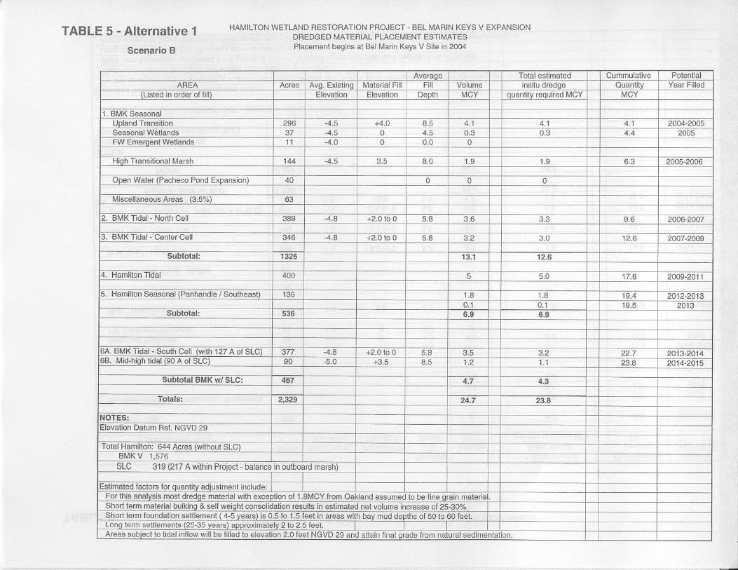
The Bel Marin Keys V (BMK-V) proposed expansion of the Hamilton Wetland Restoration Project (HWRP) is to be constructed utilizing dredged material as fill. It is estimated to require obtaining and placing approximately 24 million cubic yards (MCY) of dredged material in the combined 2,600-acre HWRP and BMK-V expansion project site.
The attached Tables 1-3 reflect the estimated dredge material quantities available considered for both the BMK-V expansion and the HWRP. Table 1 is based upon start of dredged material placement in October 2003. Table 2 is based upon beginning of placement in Spring 2004. Table 3 also depicts beginning of placement in 2004 but additionally has included one million cubic yards of dredged material from the Petaluma River (across the flats channel) Project, which is scheduled for dredging every three years.

D-8
The attached Tables 4-7 outline the sequencing of various dredge material placement options for Alternative 1, Revised Alternative 2, and Alternative 3 as described within Chapter 3 of the SEIR/EIS. All of these tables are based upon calendar years. The dredged material will be conveyed to the restoration site via pipeline from an Off-loading facility located in San Pablo Bay. Current plans for the offshore facility location and potential pipeline alignments are shown in Figure D-3. These plans will be developed further during the PED phase of the HWRP project. 5.1 Dredged Material Supply Quantity The dredged material for the expanded HWRP will be obtained from Federal Operations & Maintenance (O&M) dredging projects; the Port of Oakland 50 foot Deepening Project, and several suitable non-federal permitted projects in the San Francisco Bay area. Current plans call for the Port of Oakland Deepening Project material to be placed on the HAAF parcel, as authorized in the HWRP feasibility study. However, the availability of the BMK-V parcel will add flexibility to the construction sequence, and provide an alternative beneficial re-use site for this material should outstanding base closure procedures on the HAAF parcel temporarily delay the construction schedule on that portion of the project. The dredged material from the O&M projects is considered to consist of greater than 75% silts & clay, with the exception of the Pinole Shoal Project, which is estimated to have less than 25% silts and clays. The composition of the 2.5 MCY from the Port of Oakland 50 foot Deepening Project is expected to have 1.8 MCY sand and the rest fine material. The total estimated dredge material available for the HWRP / BMK-V expansion from 2003 to 2017 is approximately 29 MCY. This is comprised of an estimated 18 MCY to 19 MCY from the Federal O&M Projects, 2.5 MCY from the Port of Oakland Deepening Project and potentially 8 MCY from the suitable, non-federal permitted projects. The source of the information developed for Tables 1 to 3 is the Moffatt & Nichol Engineers DRAFT Hamilton Off-loader quantity summary report as revised on April 29, 2002. This Moffatt & Nichol report presented estimated quantities of available dredge material from 2002 through 2010. The source of their data input is the Corps’ historical project records and the DMMO records of annual dredge quantities removed from applicable projects from 1995 to 2001.
For Tables 1-3 the Moffatt & Nichol information was extended to 2017 using the same frequency and quantity of periodic dredging. Also, the quantities for the Petaluma River (across the flats channel) were not included in the Moffatt & Nichol report and Tables 1 and 2, but are added into Table 3. Based upon a three-year cycle, at an estimated 201,000 CY per dredge episode, from 2003 to 20017 there could be an estimated additional 1 MCY available for placement at the BMK-V and HWRP if this Petaluma material is used. Also, this material should provide good native seed stock for the wetland

D-9
restoration. The Moffatt & Nichol estimated periodic dredge quantities have been rounded to the nearest 1,000 cubic yards.
The material shown for the non-federal projects represent material from 7 of the 20 permitted projects considered suitable for the Hamilton Project. This quantity represents approximately 80% of the volume of these medium size permitted projects.
It should be noted that other internal District reports related to HWRP (i.e. Oct 17, 02 – SF Bay Regional DMMP Disposal Cost Estimates) indicate quantities of dredge material for various projects that differ from those indicated in the attached tables. This may be attributable to projections based on quantities of dredged material available and not the actual pay quantity removed. It should be further noted that the estimated dredge quantities and dredging cycle for any given project can vary significantly for a given dredging event due to changes in shoaling, project funding, and other factors.
5.2 Dredged Material Placement Sequence Tables 4 through 7 outline the preliminary estimates for the dredged material placement sequence options at both BMK-V and HWRP utilizing Alternative 1, 2 & 3 of the BMK-V SEIR. For each of these estimates the BMK-V subdivided areas under the various Alternatives are as shown on the associated plan & section drawings from the SEIR/S). Table 4, Alternative 1A, reflects beginning of dredged material placement at HWRP in 2004. Table 5, Alternative 1B, reflects beginning of dredged material placement at BMK-V in 2004. Table 6, Revised Alternative 2, presents the dredged material placement for Revised Alternative 2 of the SEIR/S. Finally, Table 7, Alternative 3, presents the estimated sequencing and quantity for Alternative 3 of the SEIR/S. The Revised Alternative 2 reflects the incorporation of review comments to the Draft SEIR/S and GRR. This includes revisions to internal area acreages and fill elevations. Also included in the Revised Alternative 2 dredge material quantity estimate is an adjustment utilizing a uniform existing site elevation of 5.0 feet below NGVD 1929 5.3 Dredged Material Quantity Adjustments Used For Alternative 1 & 3 of the preliminary estimate of dredge material quantity required, a material bulking factor of 40% for fine material was used. The estimated self-weight consolidation for the material in a 4 to 5 year period is 15%. The combined material bulking and self weight consolidation factor of the dredged material was estimated to be 25 %. Since the approximate 1 MCY of sandy material from Pinole Shoals was left in the evaluation as fine material the 25% combined bulking and consolidation estimate is considered conservative.

D-10
In Alternatives 1& 3 for the areas not subjected to tidal inundation it may be reasonable to consider the volume reduction attributable to a longer period of settlement of 25 or more years. During this period dredge material fills of 5 to 7 feet may settle 1.5 to 2.5 feet. It is therefore considered that the foundation settlement in the non-tidal areas offsets the residual bulking factor of the dredged material. Therefore, no quantity reduction adjustments were made for material to be placed in the non-tidal areas of the proposed site in the results presented in Tables 4, 5, & 7. For the tidal areas however, a conservative approach was taken in assuming dredge fill could not initially exceed an elevation of +2.0 NGVD which limited the maximum potential fill in these areas. For Revised Alternative 2, an adjustment was made to include the projected 1.0 MCY of sandy material from Pinole Shoal expected and other refinements, resulting in an approximate net material bulking rate used of 35 % instead of the 40% used for Alternatives 1 & 3. The self-weight consolidation was also estimated at 15%. It was also assumed that tidal area fill placement could temporarily exceed + 2.0 elevation. The settlement in the tidal areas used is 1.0 foot which is the expected settlement assumed after 3 years of material placement in tidal areas. This projected settlement together with the self-weight consolation and adjustments made for sandy material from Pinole Shoal is estimated to offset the residual bulking factor of the placed dredged material. The Tables 4,5 & 7 were developed utilizing a conservative approach relative to maintaining dredge fill below the +2.0 feet NGVD 1929 in the tidal cell areas. Sufficient dredge material quantities are available if there is a requirement for additional material to bring any fill area up to final grade. A detailed design considering all of the various factors associated with determination of actual quantities required will include a detailed recent survey of the site, site foundation analysis, plus material samples and analysis from all potential main sources of dredged material to evaluate more precisely the material characteristics including bulking and consolidation rates. 5.4 Process Water Control During construction, allowances will need to be made for controlling the process water associated with hydraulic dredged material placement, rainwater, and off-site discharges entering the sites.
The process water control required on the expanded project could vary substantially depending on the type of materials placed in the site (sand vs. fine-grained) and if the site is de-watered with pumps or allowed to pond to inter-tidal levels and drained through weirs. If large quantities of sandy materials were to be placed on interior portions of the site, it would be preferable to keep the site dewatered with temporary ditches and pumps during these activities to allow site access. If predominantly fine-grained materials are placed into the site, interior site access may not be required and ponding to inter-tidal levels and dewatering with weirs would be the cost effective option. Ponding to inter-tidal levels may also be preferable to keep the material in a saturated condition. Water

D-11
quality control is not expected to be a problem on these sites for sandy or fine-grained fills.
If pumping is the required or preferred method to dewater the site, the pumps should be specified, supplied, operated, and maintained by the contractor filling the site. The construction contract should clearly indicate the nature and variability of rain and off-site discharges into the site and make the management of those waters the contractor’s responsibility.
If significant quantities of fine-grained materials are placed and the site is de-watered by pumps it may be desirable to have a sediment settling basin to control turbidity and provide temporary storage for process water or other waters. For both sites, a sediment settling basin could be placed near the future levee breach area, a location where no fill is required. These basins would typically be constructed with a low dike of native materials with a crest elevation 1 to 2 feet above the preferred water ponding elevation. Water would enter these areas through weirs in the dike.
If the site is to be drained by weirs they should be designed to accommodate significant storm water flows as well as the expected process water quantities. It must be noted that storm conditions in this area are frequently accompanied by high tides, storm surges, and wind wave conditions that may severely limit or preclude dewatering the site by gravity. Recently, conditions of this type have persisted for a week or more. If weirs are used to dewater the site the sediment settling basins would not be a necessary project feature and would be expensive to construct due to the cost of building a dike for this basin to above inter-tidal elevations.
When fine-grained fill is hydraulically placed into the tidal wetland restoration areas on the combined Hamilton and BMK expanded site, it will be low-density fluid mud. Prior to breaching the levees and restoring tidal action to these sites, the material will require time to consolidate. Similar projects have allowed approximately 6-12 months for this consolidation. During this consolidation period, the material typically remains inundated to preclude chemistry changes that could be detrimental to wetland habitat. The dredged material may be placed to a maximum final elevation of +2 feet NGVD in these areas and the water level during consolidation should remain slightly above the material surface. Therefore, assuming the template is fully constructed, the maximum water elevation in the site during the consolidation period would be approximately +3 feet NGVD. 6. Construction Schedule
For the authorized HWRP (without BMK-V), the current construction schedule is for site preparation construction to start in FY-2003 or early FY-2004. Initial dredged material placement is scheduled to start in FY-2004. Site preparation will continue on sequential portions of the site during dredged material placement. Dredged material placement will likely be completed in FY-2008. All site construction, including levee breaches and tidal
D-12
channel construction should be complete by FY-2010. For the combined HWRP and BMK-V project the proposed construction sequence is to complete all dredged material placement at the Hamilton Airfield and then begin dredged material placement at the BMK-V site, including the State Lands Commission Parcel. For the combined project the proposed construction schedule is for site preparation construction to start in FY-2003 or early FY-2004 at the Hamilton Airfield. Initial dredged material placement is proposed to begin at the Hamilton Airfield in FY-2004 and continue through FY-2006. Site preparation construction at the BMK-V site would likely begin in FY-2004 or 2005. Initial dredged material placement is proposed to begin at the BMK-V site in FY-2007 and continue through FY-2015. Each of the tidal wetlands restoration areas would likely have the levee breach and tidal channel construction complete within two years after the final placement of dredged material. All site construction would likely be complete by FY-2016 to 2018. All tidal wetlands restoration areas will able to be breached within eight years of site preparation. In the event that the Hamilton Airfield (BRAC) parcel or the State Lands Commission (FUDS) parcel are not ready for restoration construction on the schedule proposed above, construction on the BMK-V site could begin earlier. Construction on the BRAC and FUDS parcels could then begin at any convenient time up to about FY-2009 or 2010.


New Levee Bel Marin KeysSouth Lagoon
02296.02-004 10/15/02
Existing ground, elevation -5’ NGVD (typical)
Elev
atio
n NG
VD (f
eet)
12-16’
8-12’
15
10
5
– 5
0
New Levee Structure 100-year tide ~ 6.5’ NGVDMHHW ~ 3.0 to 4.0’ NGVD2 foot settlement to design height of 8' NGVD
Outboard Inboard
12-16’
Structural Levee
31
31
Elev
atio
n NG
VD (f
eet) 15
10
5
– 5
0
Internal Peninsulas
InternalPeninsula
31
31
Existing ground, elevation -5’ NGVD (typical)
Elev
atio
n NG
VD (f
eet) 15
10
5
– 5
0
Improved Levee Structure 1 foot settlement to design height of 5' NGVDExisting BMK South Lagoon levee is mostly at elevations around 5' NGVD with several low points around 2–3' NGVD.
Existing ground, elevation -5’ NGVD (typical)
Novato Sanitary District Access Berm
HAAF Parcel BMKV Expansion Site
12-16’
Elev
atio
n NG
VD (f
eet) 15
10
5
– 5
0
31
Existing ground, elevation -5’ NGVD (typical)
AccessBerm
b, c, d
a
31
21
ExistingLevee
Figure D-2Typical New and Improved
Levee Cross Sections –Revised Alternative 2
Jones & Stokes
Notes:
a The 100-year tide is based on an estimate of 6.5 feet NGVD by the USACE (1984). For design purposes, this has been adjusted upward to 7 feet to account for the effects of a number of factors: mean sea level rise; wind-induced set-up within San Pablo Bay; wave runup on the adjacent mudflat; flood runoff from the Sacramento-San Joaquin Delta; and uncertainties in the estimation methods (U.S. Army Corps of Engineers 1998).
b Under Revised Alternative 2, access will be provided by the new levee constructed along the southern perimeter of the seasonal wetland habitat area and the access berm.
c Under Alternative 3, an intertidal bench will be constructed along the northern side of the access berm adjacent to the BMKV Expansion Site.
d The height of the access berm would be between 4 and 6 feet. Under Revised Alternative 2, the portion of the access berm adjacent to the seasonal wetland area at BMKV will be 7 feet.