appendix c pwc product manual - home - ntepa · an option for lateral restraint of the...
TRANSCRIPT
Appendix C PWC Product Manual
Last updated Jan 2007
Water Supply and Sewerage Approved Products Manual - February 2006
Pressure Sewerage Products – Ductile Iron Pipeline System
Section SPPS 01

DUCTILE IRON PIPELINE SYSTEM CONTENTS
PRESSURE SEWERAGE PRODUCTSSection SPPS01 Power and Water – Water Supply and Sewerage Approved Products Manual – January 2007 TOC
SPECIFICATIONS ASPPS 01-S1 SPIGOT-SOCKET PIPES TO AS/NZS 2280 ASPPS 01-S3 FLANGED PIPES TO AS/NZS 2280 CSPPS 01-S4 FITTINGS TO AS/NZS 2280 DSPPS 01-S5 JOINT SEALS FOR AS/NZS 2280 PIPES/FITTINGS ESPPS 01-S7 JOINTING LUBRICANT F
PIPE 1SPIGOT-SOCKET PIPES 1FLANGE-FLANGE PIPES 1
BENDS 2SOCKET-SOCKET BENDS 2SPIGOT-SPIGOT BENDS 3FLANGE-FLANGE BENDS 4
TEES 5SOCKET-SOCKET FLANGE SCOUR TEES 5SPIGOT-SPIGOT FLANGE SCOUR TEES 5SOCKET-SPIGOT-FLANGE GAS RELEASE VALVE TEES 6SPIGOT-SPIGOT-FLANGE GAS RELEASE VALVE TEES 7
CONNECTORS 8FLANGE-SPIGOT CONNECTORS 8FLANGE-SOCKET CONNECTORS 8SOCKET-SOCKET CONNECTORS 9SOCKET-SOCKET SLIP COLLARS 9
END SEALS 10CAPS 10PLUGS 10
FLANGES 11STANDARD PRESSURE BLANK FLANGES 11PUDDLE FLANGES 11
DISMANTLING JOINTS 12NON-THRUST DISMANTLING JOINTS CLASS 16 12THRUST DISMANTLING JOINTS CLASS 16 12
JOINT SEALS 13SPIGOT-SOCKET ELASTOMERIC SEALS 13SPIGOT-SOCKET RESTRAINING ELASTOMERIC SEALS 13FLANGE ELASTOMERIC SEALS 14JOINTING LUBRICANT 14
EXTERNAL CORROSION PROTECTION 15
DUCTILE IRON PIPELINE SYSTEM SPECIFICATIONS
PRESSURE SEWERAGE PRODUCTSSection SPPS01 Power and Water – Water Supply and Sewerage Approved Products Manual – January 2007 Page A
SPECIFICATIONS
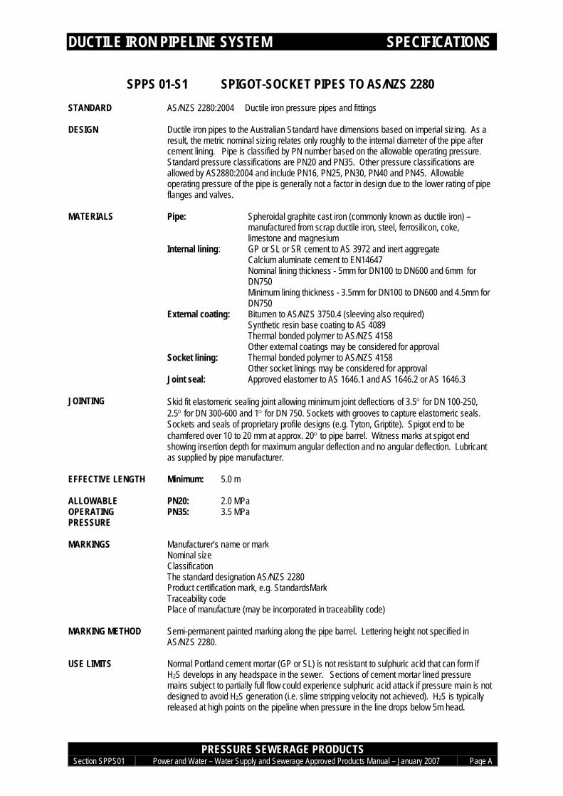
SPPS 01-S1 SPIGOT-SOCKET PIPES TO AS/NZS 2280STANDARD AS/NZS 2280:2004 Ductile iron pressure pipes and fittings
DESIGN Ductile iron pipes to the Australian Standard have dimensions based on imperial sizing. As aresult, the metric nominal sizing relates only roughly to the internal diameter of the pipe aftercement lining. Pipe is classified by PN number based on the allowable operating pressure.Standard pressure classifications are PN20 and PN35. Other pressure classifications areallowed by AS2880:2004 and include PN16, PN25, PN30, PN40 and PN45. Allowableoperating pressure of the pipe is generally not a factor in design due to the lower rating of pipeflanges and valves.
MATERIALS Pipe: Spheroidal graphite cast iron (commonly known as ductile iron) –manufactured from scrap ductile iron, steel, ferrosilicon, coke,limestone and magnesium
Internal lining: GP or SL or SR cement to AS 3972 and inert aggregateCalcium aluminate cement to EN14647Nominal lining thickness - 5mm for DN100 to DN600 and 6mm forDN750Minimum lining thickness - 3.5mm for DN100 to DN600 and 4.5mm forDN750
External coating: Bitumen to AS/NZS 3750.4 (sleeving also required)Synthetic resin base coating to AS 4089Thermal bonded polymer to AS/NZS 4158Other external coatings may be considered for approval
Socket lining: Thermal bonded polymer to AS/NZS 4158Other socket linings may be considered for approval
Joint seal: Approved elastomer to AS 1646.1 and AS 1646.2 or AS 1646.3
JOINTING Skid fit elastomeric sealing joint allowing minimum joint deflections of 3.5° for DN 100-250,2.5° for DN 300-600 and 1° for DN 750. Sockets with grooves to capture elastomeric seals.Sockets and seals of proprietary profile designs (e.g. Tyton, Griptite). Spigot end to bechamfered over 10 to 20 mm at approx. 20° to pipe barrel. Witness marks at spigot endshowing insertion depth for maximum angular deflection and no angular deflection. Lubricantas supplied by pipe manufacturer.
EFFECTIVE LENGTH Minimum: 5.0 m
PN20: 2.0 MPaALLOWABLEOPERATINGPRESSURE
PN35: 3.5 MPa
MARKINGS Manufacturer’s name or markNominal sizeClassificationThe standard designation AS/NZS 2280Product certification mark, e.g. StandardsMarkTraceability codePlace of manufacture (may be incorporated in traceability code)
MARKING METHOD Semi-permanent painted marking along the pipe barrel. Lettering height not specified inAS/NZS 2280.
USE LIMITS Normal Portland cement mortar (GP or SL) is not resistant to sulphuric acid that can form ifH2S develops in any headspace in the sewer. Sections of cement mortar lined pressuremains subject to partially full flow could experience sulphuric acid attack if pressure main is notdesigned to avoid H2S generation (i.e. slime stripping velocity not achieved). H2S is typicallyreleased at high points on the pipeline when pressure in the line drops below 5m head.
DUCTILE IRON PIPELINE SYSTEM SPECIFICATIONS
PRESSURE SEWERAGE PRODUCTSSection SPPS01 Power and Water – Water Supply and Sewerage Approved Products Manual – January 2007 Page B
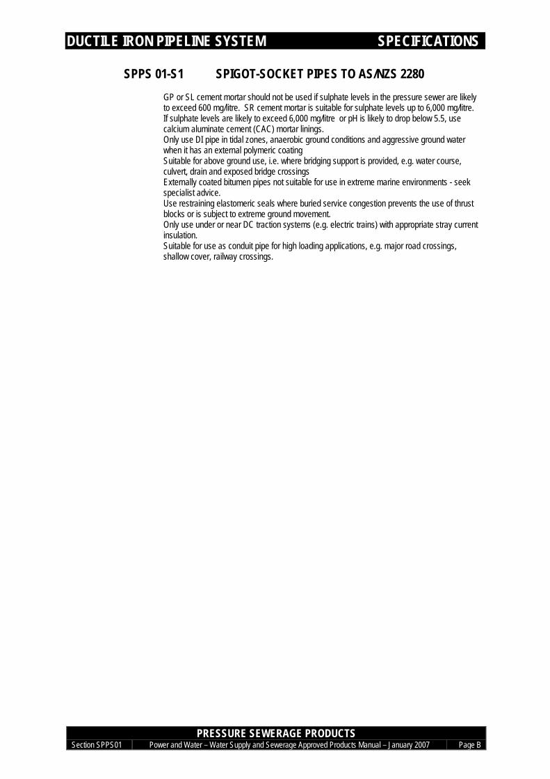
SPPS 01-S1 SPIGOT-SOCKET PIPES TO AS/NZS 2280GP or SL cement mortar should not be used if sulphate levels in the pressure sewer are likelyto exceed 600 mg/litre. SR cement mortar is suitable for sulphate levels up to 6,000 mg/litre.If sulphate levels are likely to exceed 6,000 mg/litre or pH is likely to drop below 5.5, usecalcium aluminate cement (CAC) mortar linings.Only use DI pipe in tidal zones, anaerobic ground conditions and aggressive ground waterwhen it has an external polymeric coatingSuitable for above ground use, i.e. where bridging support is provided, e.g. water course,culvert, drain and exposed bridge crossingsExternally coated bitumen pipes not suitable for use in extreme marine environments - seekspecialist advice.Use restraining elastomeric seals where buried service congestion prevents the use of thrustblocks or is subject to extreme ground movement.Only use under or near DC traction systems (e.g. electric trains) with appropriate stray currentinsulation.Suitable for use as conduit pipe for high loading applications, e.g. major road crossings,shallow cover, railway crossings.
DUCTILE IRON PIPELINE SYSTEM SPECIFICATIONS
PRESSURE SEWERAGE PRODUCTSSection SPPS01 Power and Water – Water Supply and Sewerage Approved Products Manual – January 2007 Page C
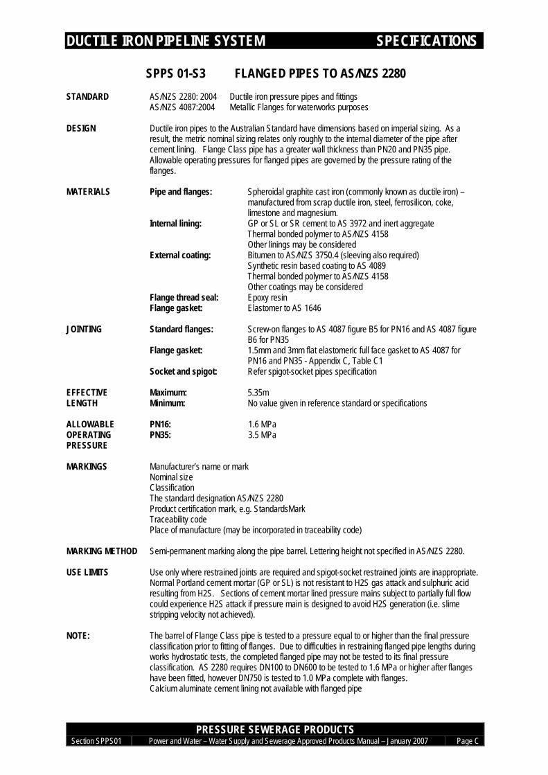
SPPS 01-S3 FLANGED PIPES TO AS/NZS 2280STANDARD AS/NZS 2280: 2004 Ductile iron pressure pipes and fittings
AS/NZS 4087:2004 Metallic Flanges for waterworks purposes
DESIGN Ductile iron pipes to the Australian Standard have dimensions based on imperial sizing. As aresult, the metric nominal sizing relates only roughly to the internal diameter of the pipe aftercement lining. Flange Class pipe has a greater wall thickness than PN20 and PN35 pipe.Allowable operating pressures for flanged pipes are governed by the pressure rating of theflanges.
MATERIALS Pipe and flanges: Spheroidal graphite cast iron (commonly known as ductile iron) –manufactured from scrap ductile iron, steel, ferrosilicon, coke,limestone and magnesium.
Internal lining: GP or SL or SR cement to AS 3972 and inert aggregateThermal bonded polymer to AS/NZS 4158Other linings may be considered
External coating: Bitumen to AS/NZS 3750.4 (sleeving also required)Synthetic resin based coating to AS 4089Thermal bonded polymer to AS/NZS 4158Other coatings may be considered
Flange thread seal: Epoxy resinFlange gasket: Elastomer to AS 1646
JOINTING Standard flanges: Screw-on flanges to AS 4087 figure B5 for PN16 and AS 4087 figureB6 for PN35
Flange gasket: 1.5mm and 3mm flat elastomeric full face gasket to AS 4087 forPN16 and PN35 - Appendix C, Table C1
Socket and spigot: Refer spigot-socket pipes specification
Maximum: 5.35mEFFECTIVELENGTH Minimum: No value given in reference standard or specifications
PN16: 1.6 MPaALLOWABLEOPERATINGPRESSURE
PN35: 3.5 MPa
MARKINGS Manufacturer’s name or markNominal sizeClassificationThe standard designation AS/NZS 2280Product certification mark, e.g. StandardsMarkTraceability codePlace of manufacture (may be incorporated in traceability code)
MARKING METHOD Semi-permanent marking along the pipe barrel. Lettering height not specified in AS/NZS 2280.
USE LIMITS Use only where restrained joints are required and spigot-socket restrained joints are inappropriate.Normal Portland cement mortar (GP or SL) is not resistant to H2S gas attack and sulphuric acidresulting from H2S. Sections of cement mortar lined pressure mains subject to partially full flowcould experience H2S attack if pressure main is designed to avoid H2S generation (i.e. slimestripping velocity not achieved).
NOTE: The barrel of Flange Class pipe is tested to a pressure equal to or higher than the final pressureclassification prior to fitting of flanges. Due to difficulties in restraining flanged pipe lengths duringworks hydrostatic tests, the completed flanged pipe may not be tested to its final pressureclassification. AS 2280 requires DN100 to DN600 to be tested to 1.6 MPa or higher after flangeshave been fitted, however DN750 is tested to 1.0 MPa complete with flanges.Calcium aluminate cement lining not available with flanged pipe

DUCTILE IRON PIPELINE SYSTEM SPECIFICATIONS
PRESSURE SEWERAGE PRODUCTSSection SPPS01 Power and Water – Water Supply and Sewerage Approved Products Manual – January 2007 Page D
SPPS 01-S4 FITTINGS TO AS/NZS 2280STANDARD AS/NZS 2280: 2004 Ductile iron pressure pipes and fittings
AS/NZS 4087:2004 Metallic Flanges for waterworks purposes
DESIGN Ductile iron fittings to the Australian Standard have dimensions based on imperial sizing. As aresult, the metric nominal sizing relates only roughly to the internal diameter after cement lining.
MATERIALS Fitting: Spheroidal graphite cast iron to AS 1831(commonly known as ductile iron)– manufactured from scrap ductile iron, steel, ferrosilicon, coke, limestoneand magnesium
Internal lining: Thermal bonded polymer to AS/NZS 4158External coating: Thermal bonded polymer to AS/NZS 4158Joint seal: Elastomer to AS 1646
JOINTING Socket: Sockets with grooves to capture elastomeric seals. Sockets and seals ofproprietary profile designs (e.g. Tyton, Griptite). Allowable minimum jointdeflections of 3.5’ for DN 100-250, 2.5° for DN 300-600 and 1° for DN 750.Jointing lugs on 90° and 45° bends for sizes DN 200 and greater.
Spigot: End to be chamfered over 10 to 20 mm at approximately 20° to pipe barrel.Jointing lugs on 90° and 45° bends for sizes DN 200 and greater.
Flange: Integral flanges to AS 4087 figure B5 for PN16 and figure B6 for PN35.1.5mm and 3mm flat elastomeric full face gasket to AS 4087 for PN16 andPN35 - Appendix C, Table C1
ALLOWABLEOPERATINGPRESSURE
PN16:PN35:
1.6 MPa3.5 MPa
MARKINGS Manufacturer’s name or mark cast onNominal sizeDuctile or DI moulded in raised formWhere applicable, the angle of the bend cast onThe standard designation AS/NZS 2280Product certification mark, e.g. StandardsMarkTraceability codePlace of manufacture (may be incorporated in traceability code)
MARKING METHOD Clearly and indelibly marked on the fitting. Lettering heights and raised height not specified inAS/NZS 2280.
DUCTILE IRON PIPELINE SYSTEM SPECIFICATIONS
PRESSURE SEWERAGE PRODUCTSSection SPPS01 Power and Water – Water Supply and Sewerage Approved Products Manual – January 2007 Page E
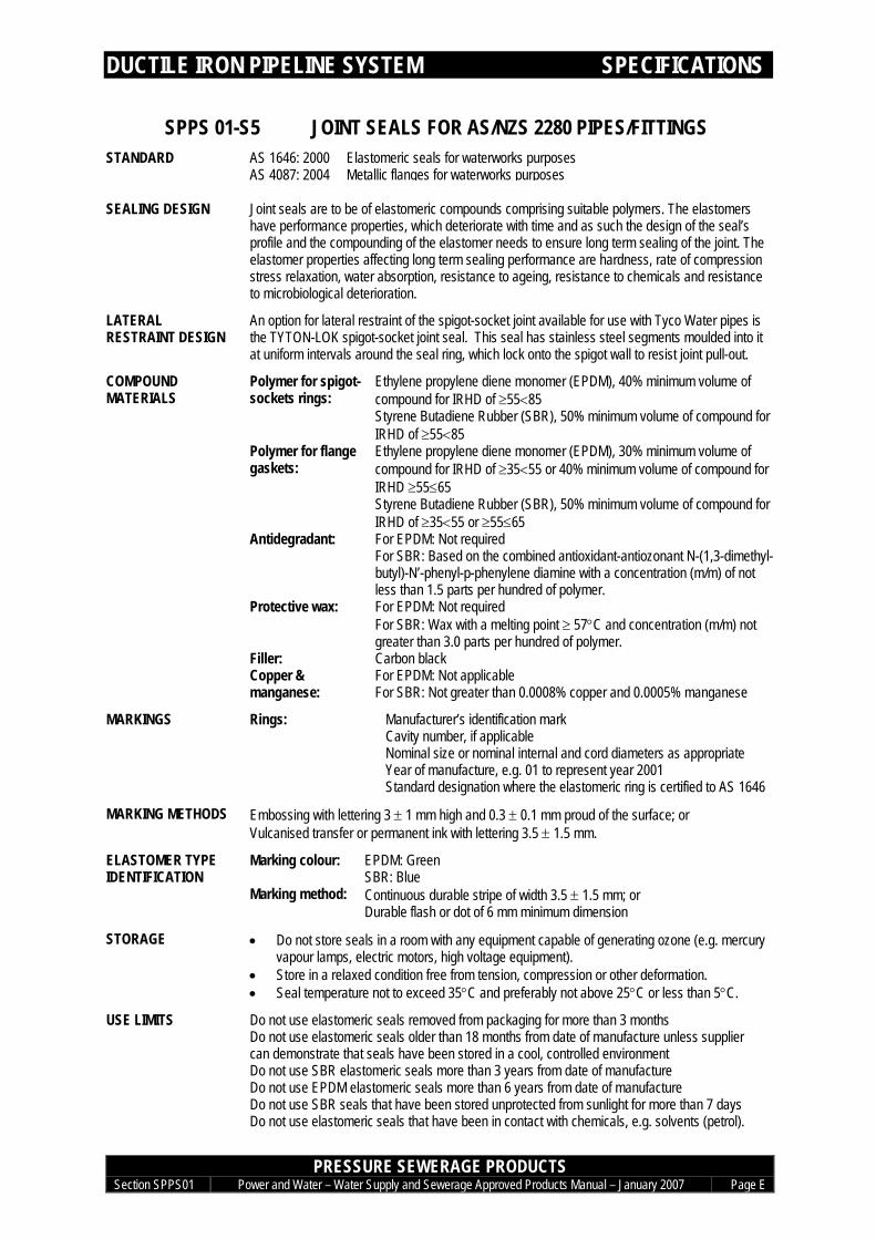
SPPS 01-S5 JOINT SEALS FOR AS/NZS 2280 PIPES/FITTINGSSTANDARD AS 1646: 2000 Elastomeric seals for waterworks purposes
AS 4087: 2004 Metallic flanges for waterworks purposes
SEALING DESIGN Joint seals are to be of elastomeric compounds comprising suitable polymers. The elastomershave performance properties, which deteriorate with time and as such the design of the seal’sprofile and the compounding of the elastomer needs to ensure long term sealing of the joint. Theelastomer properties affecting long term sealing performance are hardness, rate of compressionstress relaxation, water absorption, resistance to ageing, resistance to chemicals and resistanceto microbiological deterioration.
LATERALRESTRAINT DESIGN
An option for lateral restraint of the spigot-socket joint available for use with Tyco Water pipes isthe TYTON-LOK spigot-socket joint seal. This seal has stainless steel segments moulded into itat uniform intervals around the seal ring, which lock onto the spigot wall to resist joint pull-out.
COMPOUNDMATERIALS
Polymer for spigot-sockets rings:
Ethylene propylene diene monomer (EPDM), 40% minimum volume ofcompound for IRHD of ≥55<85Styrene Butadiene Rubber (SBR), 50% minimum volume of compound forIRHD of ≥55<85
Polymer for flangegaskets:
Ethylene propylene diene monomer (EPDM), 30% minimum volume ofcompound for IRHD of ≥35<55 or 40% minimum volume of compound forIRHD ≥55≤65Styrene Butadiene Rubber (SBR), 50% minimum volume of compound forIRHD of ≥35<55 or ≥55≤65
Antidegradant: For EPDM: Not requiredFor SBR: Based on the combined antioxidant-antiozonant N-(1,3-dimethyl-butyl)-N’-phenyl-p-phenylene diamine with a concentration (m/m) of notless than 1.5 parts per hundred of polymer.
Protective wax: For EPDM: Not requiredFor SBR: Wax with a melting point ≥ 57°C and concentration (m/m) notgreater than 3.0 parts per hundred of polymer.
Filler: Carbon blackCopper &manganese:
For EPDM: Not applicableFor SBR: Not greater than 0.0008% copper and 0.0005% manganese
MARKINGS Rings: Manufacturer’s identification markCavity number, if applicableNominal size or nominal internal and cord diameters as appropriateYear of manufacture, e.g. 01 to represent year 2001Standard designation where the elastomeric ring is certified to AS 1646
MARKING METHODS Embossing with lettering 3 ± 1 mm high and 0.3 ± 0.1 mm proud of the surface; orVulcanised transfer or permanent ink with lettering 3.5 ± 1.5 mm.
Marking colour: EPDM: GreenSBR: Blue
ELASTOMER TYPEIDENTIFICATION
Marking method: Continuous durable stripe of width 3.5 ± 1.5 mm; orDurable flash or dot of 6 mm minimum dimension
STORAGE • Do not store seals in a room with any equipment capable of generating ozone (e.g. mercuryvapour lamps, electric motors, high voltage equipment).
• Store in a relaxed condition free from tension, compression or other deformation.• Seal temperature not to exceed 35°C and preferably not above 25°C or less than 5°C.
USE LIMITS Do not use elastomeric seals removed from packaging for more than 3 monthsDo not use elastomeric seals older than 18 months from date of manufacture unless suppliercan demonstrate that seals have been stored in a cool, controlled environmentDo not use SBR elastomeric seals more than 3 years from date of manufactureDo not use EPDM elastomeric seals more than 6 years from date of manufactureDo not use SBR seals that have been stored unprotected from sunlight for more than 7 daysDo not use elastomeric seals that have been in contact with chemicals, e.g. solvents (petrol).

DUCTILE IRON PIPELINE SYSTEM SPECIFICATIONS
PRESSURE SEWERAGE PRODUCTSSection SPPS01 Power and Water – Water Supply and Sewerage Approved Products Manual – January 2007 Page F
SPPS 01-S7 JOINTING LUBRICANTSTANDARD None
DESIGN Jointing lubricant is to achieve the following:• Provide sufficient lubrication to prevent damage to joint seals or surfaces on jointing.• Enable correctly configured jointing when using jointing methods recommended by the
pipe or fitting manufacturer.• Not affect the elastomer or pipe or fitting materials.• Remain an effective lubricant under wet conditions.• Not be hazardous to handle and able to be applied by hand.• Be completely soluble in water.• Able to be removed under standard flushing arrangements for commissioning.
MATERIALS Lubricant: Water based emulsion
CONTAINER MARKINGS Manufacturer’s name or trademarkProprietary name of joint seal with which the lubricant can be used.The words ‘Jointing Lubricant’ or ‘Joint Lubricant’.Date of manufacture.Date of expiry for use.Instructions for use of lubricant
USE LIMITS Do not use where past expiry date.

DUCTILE IRON PIPELINE SYSTEM PIPES
PRESSURE SEWERAGE PRODUCTSSection SPPS01 Power and Water – Water Supply and Sewerage Approved Products Manual – January 2007 Page 1
PIPE
SPIGOT-SOCKET PIPES
Nominal sizeDN
Tyco WaterTytonExtreme
PN20
Tyco WaterTytonExtreme
PN35100 a150 a200 a225 a a250 a a300 a a375 a a450 a a500 a a600 a a750 a a
NOTES1. TytonExtreme pipe is lined with calcium aluminate cement
FLANGE-FLANGE PIPES
Nominal sizeDN
Tyco Water
100 a150 a200 a225 a250 a300 a375 a450 a500 a600 a750 a
NOTES1. Flanged pipes coated internally and externally with thermal bonded coating - available in lengths up to 2.7m2. Not available with calcium aluminate cement lining
DUCTILE IRON PIPELINE SYSTEM BENDS
PRESSURE SEWERAGE PRODUCTSSection SPPS01 Power and Water – Water Supply and Sewerage Approved Products Manual – January 2007 Page 2
BENDS
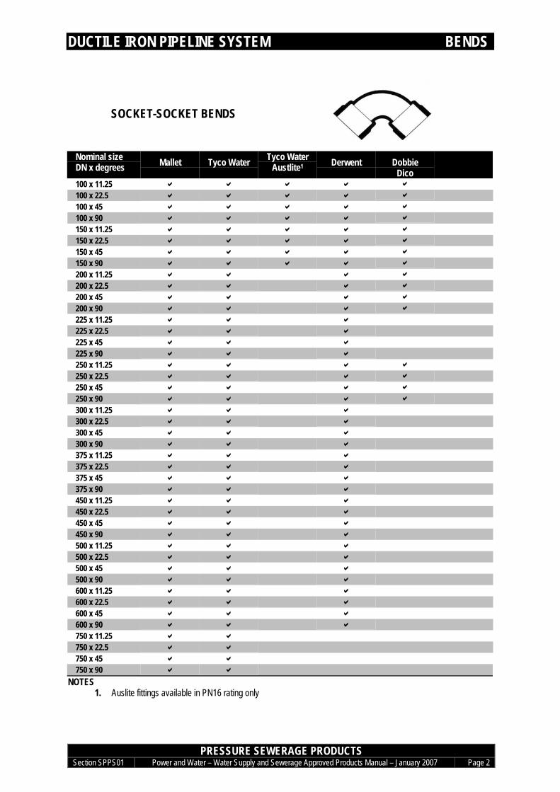
SOCKET-SOCKET BENDS
Nominal sizeDN x degrees Mallet Tyco Water Tyco Water
Austlite1 Derwent DobbieDico
100 x 11.25 a a a a a
100 x 22.5 a a a a a
100 x 45 a a a a a
100 x 90 a a a a a
150 x 11.25 a a a a a
150 x 22.5 a a a a a
150 x 45 a a a a a
150 x 90 a a a a a
200 x 11.25 a a a a
200 x 22.5 a a a a
200 x 45 a a a a
200 x 90 a a a a
225 x 11.25 a a a225 x 22.5 a a a225 x 45 a a a225 x 90 a a a250 x 11.25 a a a a
250 x 22.5 a a a a
250 x 45 a a a a
250 x 90 a a a a
300 x 11.25 a a a300 x 22.5 a a a300 x 45 a a a300 x 90 a a a375 x 11.25 a a a375 x 22.5 a a a375 x 45 a a a375 x 90 a a a450 x 11.25 a a a450 x 22.5 a a a450 x 45 a a a450 x 90 a a a500 x 11.25 a a a500 x 22.5 a a a500 x 45 a a a500 x 90 a a a600 x 11.25 a a a600 x 22.5 a a a600 x 45 a a a600 x 90 a a a750 x 11.25 a a750 x 22.5 a a750 x 45 a a750 x 90 a a
NOTES1. Auslite fittings available in PN16 rating only

DUCTILE IRON PIPELINE SYSTEM BENDS
PRESSURE SEWERAGE PRODUCTSSection SPPS01 Power and Water – Water Supply and Sewerage Approved Products Manual – January 2007 Page 3
SPIGOT-SPIGOT BENDS
Nominal SizeDN x Degrees Mallet1 Tyco Water Derwent100 x 11.25 a a a100 x 22.5 a a a100 x 45 a a a100 x 90 a a a150 x 11.25 a a a150 x 22.5 a a a150 x 45 a a a150 x 90 a a a200 x 11.25 a a200 x 22.5 a a200 x 45 a a200 x 90 a a225 x 11.25 a a225 x 22.5 a a225 x 45 a a225 x 90 a a250 x 11.25 a a250 x 22.5 a a250 x 45 a a250 x 90 a a300 x 11.25 a a300 x 22.5 a a300 x 45 a a300 x 90 a a375 x 11.25 a a375 x 22.5 a a375 x 45 a a375 x 90 a a450 x 11.25 a a450 x 22.5 a a450 x 45 a a450 x 90 a a500 x 11.25 a a500 x 22.5 a a500 x 45 a a500 x 90 a a600 x 11.25 a a600 x 22.5 a a600 x 45 a a600 x 90 a a750 x 11.25 a750 x 22.5 a750 x 45 a750 x 90 a
NOTES1. Mallet fittings available in PN16 rating only
DUCTILE IRON PIPELINE SYSTEM BENDS
PRESSURE SEWERAGE PRODUCTSSection SPPS01 Power and Water – Water Supply and Sewerage Approved Products Manual – January 2007 Page 4
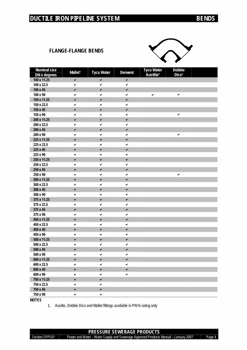
FLANGE-FLANGE BENDS
Nominal sizeDN x degrees Mallet1 Tyco Water Derwent Tyco Water
Austlite1DobbieDico1
100 x 11.25 a a a100 x 22.5 a a a100 x 45 a a a100 x 90 a a a a a150 x 11.25 a a a150 x 22.5 a a a150 x 45 a a a150 x 90 a a a a200 x 11.25 a a a200 x 22.5 a a a200 x 45 a a a200 x 90 a a a a225 x 11.25 a a a225 x 22.5 a a a225 x 45 a a a225 x 90 a a a250 x 11.25 a a a250 x 22.5 a a a250 x 45 a a a250 x 90 a a a a300 x 11.25 a a a300 x 22.5 a a a300 x 45 a a a300 x 90 a a a375 x 11.25 a a a375 x 22.5 a a a375 x 45 a a a375 x 90 a a a450 x 11.25 a a a450 x 22.5 a a a450 x 45 a a a450 x 90 a a a500 x 11.25 a a a500 x 22.5 a a a500 x 45 a a a500 x 90 a a a600 x 11.25 a a a600 x 22.5 a a a600 x 45 a a a600 x 90 a a a750 x 11.25 a a750 x 22.5 a a750 x 45 a a750 x 90 a a
NOTES1. Auslite, Dobbie Dico and Mallet fittings available in PN16 rating only
DUCTILE IRON PIPELINE SYSTEM TEES
PRESSURE SEWERAGE PRODUCTSSection SPPS01 Power and Water – Water Supply and Sewerage Approved Products Manual – January 2007 Page 5
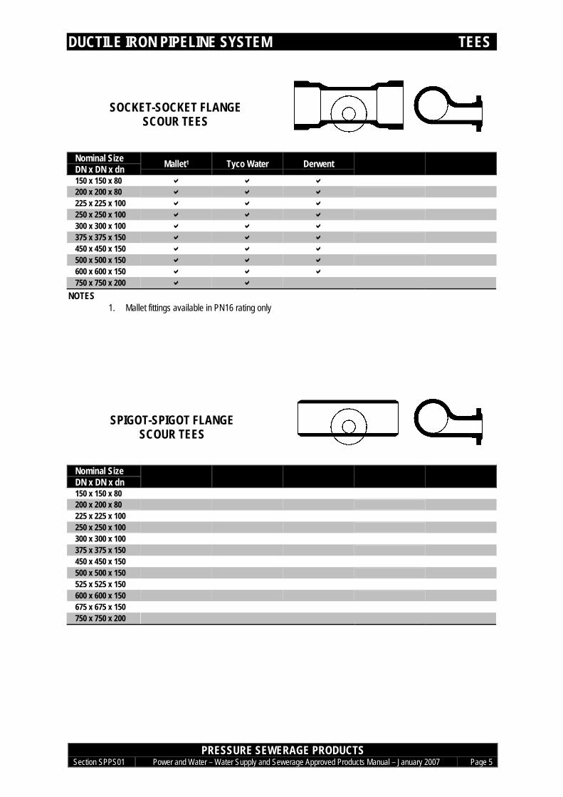
TEES
SOCKET-SOCKET FLANGESCOUR TEES
Nominal SizeDN x DN x dn Mallet1 Tyco Water Derwent150 x 150 x 80 a a a200 x 200 x 80 a a a225 x 225 x 100 a a a250 x 250 x 100 a a a300 x 300 x 100 a a a375 x 375 x 150 a a a450 x 450 x 150 a a a500 x 500 x 150 a a a600 x 600 x 150 a a a750 x 750 x 200 a a
NOTES1. Mallet fittings available in PN16 rating only
SPIGOT-SPIGOT FLANGESCOUR TEES
Nominal SizeDN x DN x dn150 x 150 x 80200 x 200 x 80225 x 225 x 100250 x 250 x 100300 x 300 x 100375 x 375 x 150450 x 450 x 150500 x 500 x 150525 x 525 x 150600 x 600 x 150675 x 675 x 150750 x 750 x 200

DUCTILE IRON PIPELINE SYSTEM TEES
PRESSURE SEWERAGE PRODUCTSSection SPPS01 Power and Water – Water Supply and Sewerage Approved Products Manual – January 2007 Page 6
SOCKET-SPIGOT-FLANGEGAS RELEASE VALVE TEES
Nominal SizeDN x dn x dn
Mallet1 Tyco Water Derwent
100 x 100 x 80 a a a100 x 100 x 100 a a a150 x 150 x 80 a a a150 x 150 x 100 a a a200 x 200 x 80 a a a200 x 200 x 100 a a a225 x 225 x 80 a a a225 x 225 x 100 a a a250 x 250 x 80 a a a250 x 250 x 100 a a a300 x 300 x 80 a a a300 x 300 x 100 a a a375 x 375 x 80 a a a375 x 375 x 100 a a a450 x 450 x 80 a a a450 x 450 x 100 a a a500 x 500 x 80 a a a500 x 500 x 100 a a a600 x 600 x 80 a a a600 x 600 x 100 a a a750 x 750 x 80750 x 750 x 100 a a
NOTES1. Mallet fittings available in PN16 rating only

DUCTILE IRON PIPELINE SYSTEM TEES
PRESSURE SEWERAGE PRODUCTSSection SPPS01 Power and Water – Water Supply and Sewerage Approved Products Manual – January 2007 Page 7
SPIGOT-SPIGOT-FLANGEGAS RELEASE VALVE TEES
Nominal SizeDN x DN x dn
Tyco Water Derwent
100 x 100 x 80 a a100 x 100 x 100 a a150 x 150 x 80 a a150 x 150 x 100 a a200 x 200 x 80 a a200 x 200 x 100 a a225 x 225 x 80 a a225 x 225 x 100 a a250 x 250 x 80 a a250 x 250 x 100 a a300 x 300 x 80 a a300 x 300 x 100 a a375 x 375 x 80 a a375 x 375 x 100 a a450 x 450 x 80 a a450 x 450 x 100 a a500 x 500 x 80 a a500 x 500 x 100 a a600 x 600 x 80 a a600 x 600 x 100 a a750 x 750 x 80750 x 750 x 100 a
DUCTILE IRON PIPELINE SYSTEM CONNECTORS
PRESSURE SEWERAGE PRODUCTSSection SPPS01 Power and Water – Water Supply and Sewerage Approved Products Manual – January 2007 Page 8
CONNECTORS
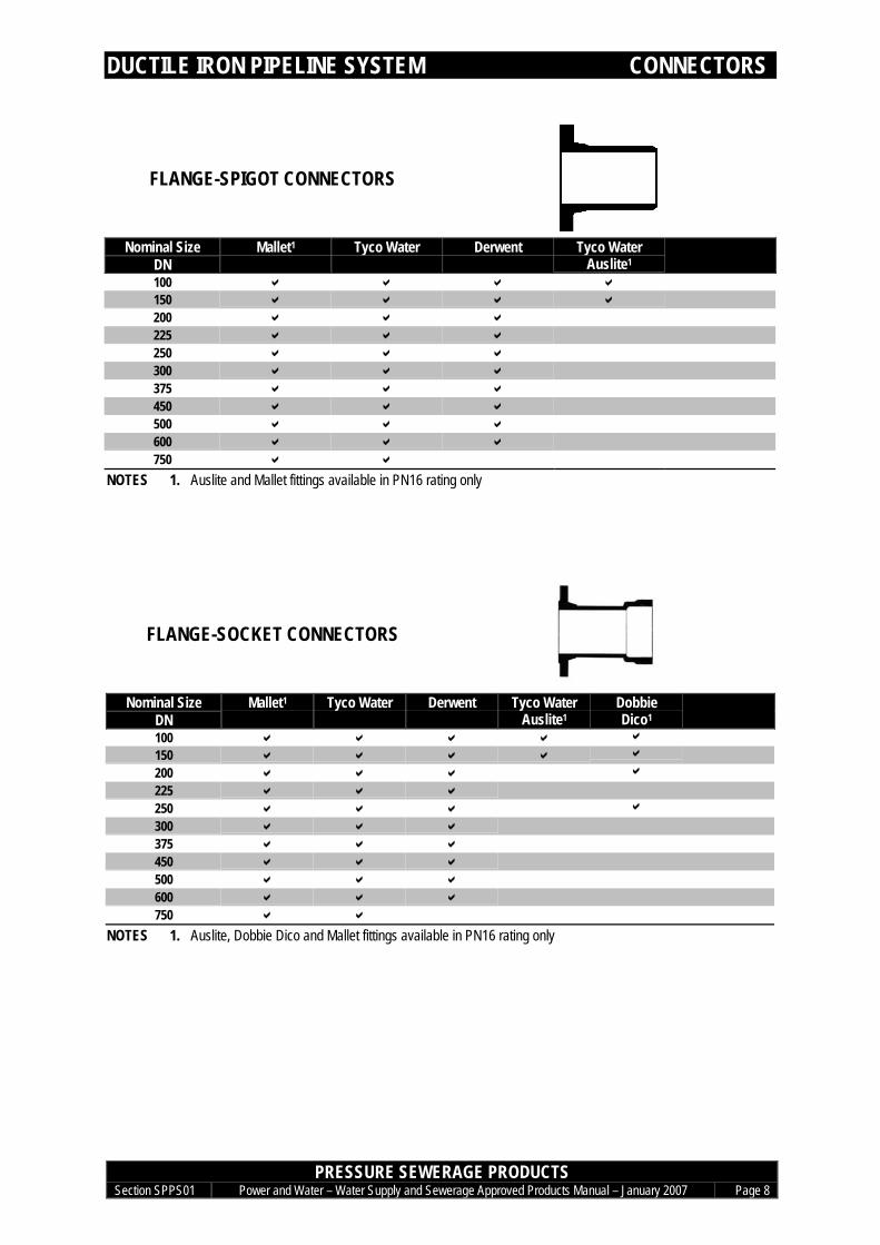
FLANGE-SPIGOT CONNECTORS
Nominal SizeDN
Mallet1 Tyco Water Derwent Tyco WaterAuslite1
100 a a a a150 a a a a200 a a a225 a a a250 a a a300 a a a375 a a a450 a a a500 a a a600 a a a750 a a
NOTES 1. Auslite and Mallet fittings available in PN16 rating only
FLANGE-SOCKET CONNECTORS
Nominal SizeDN
Mallet1 Tyco Water Derwent Tyco WaterAuslite1
DobbieDico1
100 a a a a a
150 a a a a a
200 a a a a
225 a a a250 a a a a
300 a a a375 a a a450 a a a500 a a a600 a a a750 a a
NOTES 1. Auslite, Dobbie Dico and Mallet fittings available in PN16 rating only

DUCTILE IRON PIPELINE SYSTEM CONNECTORS
PRESSURE SEWERAGE PRODUCTSSection SPPS01 Power and Water – Water Supply and Sewerage Approved Products Manual – January 2007 Page 9
SOCKET-SOCKET CONNECTORS
Nominal SizeDN
Mallet Tyco Water Derwent
100 a a a150 a a a200 a a a225 a a a250 a a a300 a a a375 a a a450 a a a500 a a a600 a a a750 a a
SOCKET-SOCKET SLIP COLLARS
Nominal Size Tyco WaterDN (Sliptyt)100 a150 a
NOTESSliptyt offered only with thermal bonded polymeric encapsulation utilising polyamide (nylon) being Rilsan T Blue 7411 MAC
DUCTILE IRON PIPELINE SYSTEM END SEALS
PRESSURE SEWERAGE PRODUCTSSection SPPS01 Power and Water – Water Supply and Sewerage Approved Products Manual – January 2007 Page 10
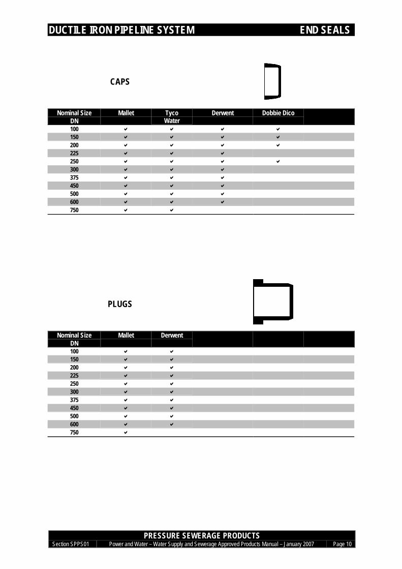
END SEALS
CAPS
Nominal SizeDN
Mallet TycoWater
Derwent Dobbie Dico
100 a a a a150 a a a a200 a a a a225 a a a250 a a a a300 a a a375 a a a450 a a a500 a a a600 a a a750 a a
PLUGS
Nominal SizeDN
Mallet Derwent
100 a a150 a a200 a a225 a a250 a a300 a a375 a a450 a a500 a a600 a a750 a
DUCTILE IRON PIPELINE SYSTEM FLANGES
PRESSURE SEWERAGE PRODUCTSSection SPPS01 Power and Water – Water Supply and Sewerage Approved Products Manual – January 2007 Page 11
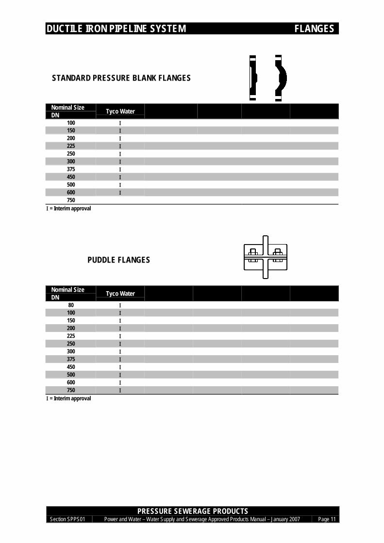
FLANGES
STANDARD PRESSURE BLANK FLANGES
Nominal SizeDN Tyco Water
100 Ι150 Ι200 Ι225 Ι250 Ι300 Ι375 Ι450 Ι500 Ι600 Ι750
Ι = Interim approval
PUDDLE FLANGES
Nominal SizeDN Tyco Water
80 Ι100 Ι150 Ι200 Ι225 Ι250 Ι300 Ι375 Ι450 Ι500 Ι600 Ι750 Ι
Ι = Interim approval
DUCTILE IRON PIPELINE SYSTEM DISMANTLING JOINTS
PRESSURE SEWERAGE PRODUCTSSection SPPS01 Power and Water – Water Supply and Sewerage Approved Products Manual – January 2007 Page 12
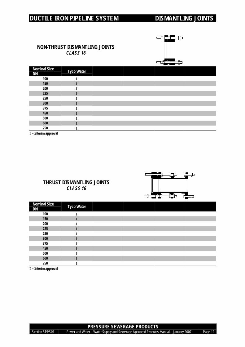
DISMANTLING JOINTS
NON-THRUST DISMANTLING JOINTSCLASS 16
Nominal SizeDN Tyco Water
100 Ι150 Ι200 Ι225 Ι250 Ι300 Ι375 Ι450 Ι500 Ι600 Ι750 Ι
Ι = Interim approval
THRUST DISMANTLING JOINTSCLASS 16
Nominal SizeDN Tyco Water
100 Ι150 Ι200 Ι225 Ι250 Ι300 Ι375 Ι450 Ι500 Ι600 Ι750 Ι
Ι = Interim approval
DUCTILE IRON PIPELINE SYSTEM JOINT SEALS
PRESSURE SEWERAGE PRODUCTSSection SPPS01 Power and Water – Water Supply and Sewerage Approved Products Manual – January 2007 Page 13
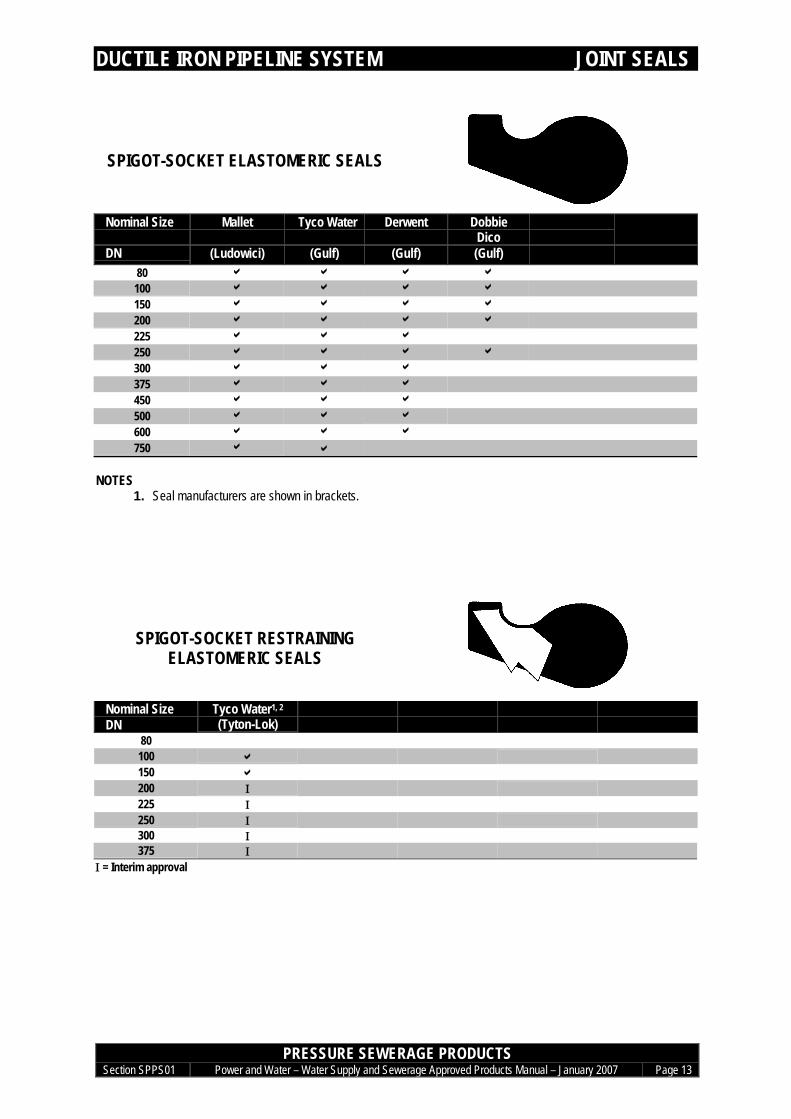
JOINT SEALS
SPIGOT-SOCKET ELASTOMERIC SEALS
Nominal Size Mallet Tyco Water Derwent DobbieDico
DN (Ludowici) (Gulf) (Gulf) (Gulf)80 a a a a
100 a a a a
150 a a a a
200 a a a a
225 a a a
250 a a a a
300 a a a
375 a a a
450 a a a
500 a a a
600 a a a
750 a a
NOTES1. Seal manufacturers are shown in brackets.
SPIGOT-SOCKET RESTRAININGELASTOMERIC SEALS
Nominal SizeDN
Tyco Water1, 2
(Tyton-Lok)80100 a150 a200 Ι225 Ι250 Ι300 Ι375 Ι
Ι = Interim approval

DUCTILE IRON PIPELINE SYSTEM JOINT SEALS
PRESSURE SEWERAGE PRODUCTSSection SPPS01 Power and Water – Water Supply and Sewerage Approved Products Manual – January 2007 Page 14
FLANGE ELASTOMERIC SEALS
Nominal Size Mallet Tyco WaterDN (Ludowici) (SDQ)
80 a a
100 a a
150 a a
200 a a
225 a a
250 a a
300 a a
375 a a
450 a a
500 a a
600 a a
750 a a
NOTES1. Seal manufacturers are shown in brackets.
JOINTING LUBRICANT
Size Tyco Water(ThomasGrozier)
500g a1kg a
2kg a
4kg a
NOTES1. Lubricant manufacturers are shown in brackets.
DUCTILE IRON PIPELINE SYSTEM CORROSION PROTECTION
PRESSURE SEWERAGE PRODUCTSSection SPPS01 Power and Water – Water Supply and Sewerage Approved Products Manual – January 2007 Page 15
EXTERNAL CORROSION PROTECTION
EXTERNAL CORROSION PROTECTIONPOLYETHYLENE SLEEVING & PETROLATUM SYSTEM
REFER TO SECTION SPO 04 CORROSION PROTECTION
Last updated Jan 2007
Water Supply and Sewerage Approved Products Manual - February 2006
Pressure Sewerage Products – PVC Metric Pipeline System
Section SPPS 02

PVC METRIC PIPELINE SYSTEM CONTENTS
PRESSURE SEWERAGE PRODUCTSSection SPPS02 Power and Water – Water Supply and Sewerage Approved Products Manual – January 2007 Page TOC
SPECIFICATIONS ASPPS 02-1 SPIGOT-SOCKET PVC-U PIPES ASPPS 02-2 SPIGOT-SOCKET PVC-M PIPES BSPPS 02-3 DUCTILE IRON FITTINGS CSPPS 02-4 JOINT SEALS DSPPS 02-5 JOINTING LUBRICANT ESPPS 02-6 SOLVENT CEMENTING FSPPS 02-7 SPIGOT-SOCKET PVC-O PIPES G
PIPES 1SPIGOT-SOCKET RRJ PIPES 1
CLASS PN 9 1CLASS PN 12 1CLASS PN 15 1CLASS PN 18 1
SPIGOT-SOCKET SCJ PIPES 2CLASS PN 9 2CLASS PN 12 2CLASS PN 15 2CLASS PN 18 2
DI BENDS 3SOCKET-SOCKET BENDS 3
DI TEES 4SOCKET-SOCKET-FLANGE SCOUR TEES 4
DI CONNECTORS 5FLANGE-SOCKET CONNECTORS 5SOCKET-SOCKET CONNECTORS 5SOCKET-SOCKET SLIP COLLARS 5
END SEALS 6CAPS 6
JOINT SEALS 7PVC SPIGOT TO PVC SOCKET 7PVC SPIGOT TO DI SOCKET ELASTOMERIC SEALS 7FLANGE ELASTOMERIC SEALS 7JOINTING LUBRICANT 8
SOLVENT CEMENTING 9SOLVENT CEMENT 9PRIMING FLUID 9
EXTERNAL CORROSION PROTECTION FOR DI FITTINGS 10

PVC METRIC PIPELINE SYSTEM SPECIFICATIONS
PRESSURE SEWERAGE PRODUCTSSection SPPS02 Power and Water – Water Supply and Sewerage Approved Products Manual – January 2007 Page A
SPECIFICATIONS
SPPS 02-1 SPIGOT-SOCKET PVC-U PIPESSTANDARD AS/NZS 1477:1999 PVC pipes and fittings for pressure applications
DESIGN Unplasticised PVC pressure pipes (PVC-U or uPVC) have a plain (solid) wall structure and aremanufactured in two standard sizings. For pressure sewers, Power and Water follows WSAACodes and uses Series 1 pipe, which conforms to the metric sizing in international pipingstandards. Pipe wall thickness is varied to achieve the desired pipe pressure rating. Pressureratings are determined at 20°C. Pressure derating is required for higher operatingtemperatures. Pressure de-rating is required to cater for fatigue issues where fluctuatingpressures occur (ie. pumped systems) – refer WSAA Technical Notes TN4 and TN5.
MATERIALS Pipe: Polyvinyl chloride (83.3 % minimum)Calcium-zinc to prevent PVC degradation from high processing temperaturesLubricants to lower the viscosity of molten PVC during pipe processingFillers, e.g. calcium carbonate, to aid pipe processingRutile titanium dioxide to prevent ultraviolet degradation and to provide whitecolouring pigment for Series 1 pipe (1.5 parts minimum per 100 parts PVC).
Joint seal: Approved elastomer to AS 1646.1 and AS 1646.2 or AS 1646.3
JOINTING Rubber ring joints are to be used unless otherwise permitted. Sockets are to have grooves tocapture elastomeric seals. Seal profiles are to manufacturers’ proprietary designs. Spigots areto have witness marks to identify socket insertion depth.
EFFECTIVE LENGTH 6 m (+0.05, -0 m)
PRESSURE CLASSES PN 9, PN 12, PN 15 and PN 18 corresponding to 0.9, 1.2, 1.5 and 1.8 MPa working pressure
MARKINGS Manufacturer’s name and registered trademarkThe pipe series number ‘1’ for metric pipe seriesThe letters ‘PVC-U’Nominal size in the form ‘100’, as appropriateClassification in the form ‘PN 12’, as appropriateFor pipes designed with deflection joints, the maximum allowable angular deflection in degreesDate of manufacture, using the ISO system in the form YYMMDDIdentification of place of manufacture. The manufacturer’s code is acceptableThe Australian Standard number, i.e. AS/NZS 1477Product certification mark, e.g. StandardsMarkWarning - ‘SEWERAGE - DO NOT DRINK’
MARKING METHOD Legible and durable marking along the pipe barrel, minimum lettering height of 3 mm for DN100 and 5 mm for greater than DN 100. Unmarked pipe length not to exceed 1 m.
USE LIMITS Do not use PVC-U for new works in sizes greater than DN 225Do not use solvent cement jointing except for unusual requirements.Do not use in ground subject to extreme movement where joint pull-out could occurDo not use above ground or in ground contaminated with chemicals deleterious to PVCDo not use pipe stored unshaded for 6 months or more from date of manufactureDo not use pipe older than 12 months from the date of manufactureDo not use pipe scratched to a depth greater than 0.5 mm (or 10% of wall thickness for sizessmaller than DN80)

PVC METRIC PIPELINE SYSTEM SPECIFICATIONS
PRESSURE SEWERAGE PRODUCTSSection SPPS02 Power and Water – Water Supply and Sewerage Approved Products Manual – January 2007 Page B
SPPS 02-2 SPIGOT-SOCKET PVC-M PIPESSTANDARD AS/NZS 4765 (Int):2000 Modified PVC (PVC-M) pipes for pressure applications
DESIGN Modified PVC (PVC-M) differs from traditional unplasticised PVC (PVC-U or uPVC) by way ofan elastomer additive of quantity sufficient to improve toughness without excessive yieldstrength reduction. Improved toughness and performance predicability allows the pressurerating design factor for PVC-M pipe to be less than that for PVC-U pipe. PVC-M pipe of thesame pressure rating as PVC-U pipe thus has a thinner wall (and lower stiffness). PVC-Mpipes have a plain (solid) wall structure. For pressure sewers, Power and Water follows WSAACodes and uses Series 1 pipe, which conforms to the metric sizing in international pipingstandards. Pipe wall thickness is varied to achieve the desired pipe pressure rating. Pressureratings are determined at 20°C. Pressure de-rating is required for higher operatingtemperatures. Pressure de-rating is required to cater for fatigue issues where fluctuatingpressures occur (ie. pumped systems) – refer WSAA Technical Notes TN4 and TN5.
MATERIALS Pipe: Polyvinyl chloride (83.3% minimum)Elastomer to improve ductility (fracture toughness)Rutile titanium dioxide to prevent ultraviolet degradation (minimum of 1.5 partsper 100 parts PVC mass)Calcium-zinc to prevent PVC degradation from high processing temperaturesLubricants to lower the viscosity of molten PVC during pipe processingFillers, e.g. calcium carbonate, to aid pipe processing
Joint seal: Approved elastomer to AS 1646.1 and AS 1646.2 or AS 1646.3
JOINTING Only rubber ring joints permitted. Sockets to have grooves to capture seals. Spigots to havewitness marks to identify socket insertion depth.
EFFECTIVE LENGTH 6 m (+0.05, -0 m)
PRESSURE CLASSES PN 9, PN 12, PN 15 and PN 18 corresponding to 0.9, 1.2, 1.5 and 1.8 MPa working pressure
MARKINGS Product code (e.g. PPRW 12225)Manufacturer’s name and registered trademarkTrade name (e.g. White Rhino) - OPTIONALThe pipe series number ‘1’ for metric pipe seriesThe letters ‘PVC-M’Nominal size in the form ‘100’, as appropriateClassification in the form ‘PN 12’, as appropriateFor pipes designed with deflection joints, the maximum allowable angular deflection in degreesDate of manufacture, using the ISO system in the form YYMMDDTime of manufacture - OPTIONALIdentification of place of manufacture. The manufacturer’s code is acceptableThe Australian Standard number, i.e. AS/NZS 4765(Int)Warning - ‘SEWERAGE - DO NOT DRINK’
MARKING METHOD Legible and durable marking along the pipe barrel, minimum lettering height of 5 mm.Unmarked pipe length not to exceed 1 m.
USE LIMITS Solvent cement joint PVC-M pipes not permittedDo not use in ground subject to extreme movement where joint pull-out could occurDo not use above ground or in ground contaminated with chemicals deleterious to PVCDo not use pipe stored unshaded for 6 months or more from date of manufactureDo not use pipe older than 12 months from the date of manufactureDo not use pipe scratched to a depth greater than 0.25 mmDo not use PVC-M pipes for new works in sizes greater than DN225 unless specific projectapproval has been granted by the Water Engineering section of Power and Water

PVC METRIC PIPELINE SYSTEM SPECIFICATIONS
PRESSURE SEWERAGE PRODUCTSSection SPPS02 Power and Water – Water Supply and Sewerage Approved Products Manual – January 2007 Page C
SPPS 02-3 DUCTILE IRON FITTINGSSTANDARD AS/NZS 2280:2004 Ductile iron pressure pipes and fittings
AS/NZS 4087:2004 Metallic Flanges for waterworks purposes
DESIGN Ductile iron fittings to the Australian Standard have dimensions based on imperial sizing. As aresult, the metric nominal sizing relates only roughly to the internal diameter after cement lining.
MATERIALS Fitting: Spheroidal graphite cast iron to AS 1831(commonly known as ductile iron) –manufactured from scrap ductile iron, steel, ferrosilicon, coke, limestone andmagnesium
Internal lining: Thermal bonded polymer to AS/NZS 4158External coating: Thermal bonded polymer to AS/NZS 4158
Other coatings may be consideredJoint seal: Elastomer type to AS 1646
JOINTING Socket: Sockets with grooves to capture elastomeric seals. Sockets and seals ofproprietary designs (e.g. Tyton/Plastyt, Nortite) to connect with metric seriesPVC pipe. Allowable minimum joint deflections of 3.5° for DN 100-250 and2.5° for DN 300-375. Jointing lugs on 90° and 45° bends for sizes DN 200and greater.
Spigot: End to be chamfered over 10 to 20 mm at approximately 20° to pipe barrel.Jointing lugs on 90° and 45° bends for sizes DN 200 and greater.
Flange: Integral flanges to AS 4087 figure B5 for PN16 and figure B6 for PN35.1.5mm and 3mm flat elastomeric full face gasket to AS 4087 for PN16 andPN35 - Appendix C, Table C1
ALLOWABLEOPERATINGPRESSURE
PN16:PN35:
1.6 MPa3.5 MPa
MARKINGS Manufacturer’s name or mark cast onNominal sizeDuctile or DI moulded in raised formWhere applicable, the angle of the bend cast onThe standard designation AS/NZS 2280Product certification mark, e.g. StandardsMarkTraceability codePlace of manufacture (may be incorporated in traceability code)
MARKING METHOD Clearly & indelibly marked on fitting. Lettering size & raised height not specified in AS/NZS 2280.

PVC METRIC PIPELINE SYSTEM SPECIFICATIONS
PRESSURE SEWERAGE PRODUCTSSection SPPS02 Power and Water – Water Supply and Sewerage Approved Products Manual – January 2007 Page D
SPPS 02-4 JOINT SEALSSTANDARD AS 1646: 2000 Elastomeric seals for waterworks purposes
AS 4087: 2004 Metallic flanges for waterworks purposes
SEALING DESIGN Joint seals are to be of elastomeric compounds comprising suitable polymers. The elastomershave performance properties which deteriorate with time and as such the design of the seal’sprofile and the compounding of the elastomer needs to ensure long term sealing of the joint.The elastomer properties affecting long term sealing performance are hardness, rate ofcompression stress relaxation, water absorption, resistance to ageing, resistance to chemicalsand resistance to microbiological deterioration.
COMPOUNDMATERIALS
Polymer for spigot-socket rings:
Ethylene propylene diene monomer (EPDM), 40% minimum volumeof compound for IRHD of ≥55<85Styrene Butadiene Rubber (SBR), 50% minimum volume ofcompound for IRHD of ≥55<85
Polymer for flangegaskets:
Ethylene propylene diene monomer (EPDM), 30% minimum volumeof compound for IRHD of ≥35<55 or 40% minimum volume ofcompound for IRHD ≥55≤65Styrene Butadiene Rubber (SBR), 50% minimum volume ofcompound for IRHD of ≥35<55 or ≥55≤65
Antidegradant: For EPDM: Not requiredFor SBR: Based on the combined antioxidant –antiozonant N-(1,3dimethy-butyl)-N’-phenyl-p-phenylene diamine with a concentration(m/m) of not less than 1.5 parts per hundred of polymer.
Protective wax: For EPDM: Not requiredFor SBR: Wax with a melting point of not less than 57°C andconcentration (m/m) not greater than 3.0 parts per hundred ofpolymer.
Filler: Carbon blackCopper & manganese: For EPDM: Not applicable
For SBR: Not greater than 0.0008% copper and 0.0005%manganese
MARKINGS Rings: Manufacturer’s identification markCavity number, if applicableNominal size or nominal internal and cord diameters as appropriateYear of manufacture, e.g. 01 to represent year 2001Standard designation where the elastomeric ring is certified to AS 1646.
MARKING METHODS Embossing with lettering 3 ± 1 mm high and 0.3 ± 0.1 mm proud of the surface; orVulcanised transfer or permanent ink with lettering 3.5 ± 1.5 mm.
Marking colour: EPDM: GreenSBR: Blue
ELASTOMER TYPEIDENTIFICATION
Marking method: Continuous durable stripe of width 3.5 ± 1.5 mm; orDurable flash or dot of 6 mm minimum dimension
STORAGE • Do not store seals in a room with any equipment capable of generating ozone (e.g. mercuryvapour lamps, electric motors, high voltage equipment).
• Store in a relaxed condition free from tension, compression or other deformation.• Seal temperature not to exceed 35°C and preferably not above 25°C or less than 5°C.
USE LIMITS Do not use elastomeric seals removed from packaging for more than 3 monthsDo not use elastomeric seals older than 18 months from date of manufacture unless suppliercan demonstrate that seals have been stored in a cool, controlled environmentDo not use SBR elastomeric seals more than 3 years for date of manufactureDo not use EPDM elastomeric seals more than 6 years for date of manufactureDo not use SBR seals that have been stored unprotected from sunlight for more than 7 daysDo not use elastomeric seals that have been in contact with chemicals, e.g. solvents (petrol).

PVC METRIC PIPELINE SYSTEM SPECIFICATIONS
PRESSURE SEWERAGE PRODUCTSSection SPPS02 Power and Water – Water Supply and Sewerage Approved Products Manual – January 2007 Page E
SPPS 02-5 JOINTING LUBRICANT
STANDARD None
SPECIFICATION MP52: None
DESIGN Jointing lubricant is required to achieve the following:• Provide sufficient lubrication to prevent damage to joint seals or surfaces on jointing.• Enable correctly configured jointing when using jointing methods recommended by the
pipe or fitting manufacturer.• Not affect the elastomer or pipe or fitting materials.• Remain an effective lubricant under wet conditions.• Not be hazardous to handle and be able to be applied by hand.• Be completely soluble in water.• Be able to be removed under standard flushing arrangements for commissioning.
MATERIALS Lubricant: Water based emulsion
CONTAINER MARKINGS Manufacturer’s name or trademarkProprietary name of joint seal with which the lubricant can be used.The words ‘Jointing Lubricant’ or ‘Joint Lubricant’.Date of manufacture.Date of expiry for use.The specification to which it compliesThe WaterMark or other mark to certify compliance with the specification.Instructions for use of lubricant.
USE LIMITS Do not use where past expiry date.

PVC METRIC PIPELINE SYSTEM SPECIFICATIONS
PRESSURE SEWERAGE PRODUCTSSection SPPS02 Power and Water – Water Supply and Sewerage Approved Products Manual – January 2007 Page F
SPPS 02-6 SOLVENT CEMENTING
STANDARD AS: 3879: 1995 Solvent cements and priming fluids for use with unplasticized PVC (uPVC)pipes and fittings
SPECIFICATION WSAA: None
DESIGN Solvent cement: The solvent in the cement softens and swells a layer of the PVC on the spigotand socket mating surfaces and these layers combine with the PVC alreadyin the solvent cement to create a bond on drying of the solvent.
Priming fluid: The priming fluid cleans the joint mating surfaces of dirt, oil and othercontamination prior to application of the solvent cement and removes thesurface sheen on the PVC to aid action of the solvent cement.
MATERIALS Solvent cement: Consists of one or more solvents and a sufficient quantity of base PVCmaterial dissolved in the solvent/s to give the cement the body andconsistency required for proper application. Small amounts of inert fillers aresometimes added to control shrinkage during drying. The principal solventused is tetrahydrofuran (THF).
Priming fluid:
Manufacturer’s nameCONTAINERMARKINGS Marking ‘Type P’ to indicate solvent cement for pressure applications.
Net mass or volumeDate of manufactureRecommended storage lifeInstructions for storage and useThe statement ‘Priming fluids shall be used to prepare the jointing surface prior to solvent cementapplication.’A statement of any toxic vapour or flammability hazards associated with the solvent cement orpriming fluid.The statement ‘No additives of any kind shall be mixed with this solvent cement/priming fluid’. (asapplicable)The number of the Australian Standard, i.e. AS/NZS 3879
Solvent cement: Green for pressure applications.COLOURPriming fluid: Pink or red
USE LIMITS Clear solvent cement is not permittedSolvent cement jointing is permitted only for unusual requirements.Do not use solvent cement where 12 months past the date on the container.

PVC METRIC PIPELINE SYSTEM SPECIFICATIONS
PRESSURE SEWERAGE PRODUCTSSection SPPS02 Power and Water – Water Supply and Sewerage Approved Products Manual – January 2007 Page G
SPPS 02-7 SPIGOT-SOCKET PVC-O PIPESSTANDARD AS/NZS 4441 (Int):2003 Oriented PVC (PVC-O) pipes for pressure applications
UNDERDEVELOPMENT

PVC METRIC PIPELINE SYSTEM PIPES
PRESSURE SEWERAGE PRODUCTSSection SPPS02 Power and Water – Water Supply and Sewerage Approved Products Manual – January 2007 Page 1
PIPES
SPIGOT-SOCKET RRJ PIPES
CLASS PN 9Nominal size Iplex Iplex Iplex Tyco Tyco Vinidex
DN (PVC-U) (PVC-M) (PVC-M)Reiber Joint
(PVC-U)Plas-flo
(PVC-M)Tuf-flo
(PVC-M)
80 a a
100 a a a150 a a a200 a a a225 a a a250 a a1 a1
300 a1 a1 a1
375 a1 a1 a1
CLASS PN 12Nominal size Iplex Iplex Iplex Tyco Tyco Vinidex
DN (PVC-U) (PVC-M) (PVC-M)Rieber Joint
(PVC-U)Plas-flo
(PVC-M)Tuf-flo
(PVC-M)
80 a a
100 a a a150 a a a200 a a a225 a a a250 a1 a1 a1
300 a1 a1 a1
375 a1 a1,2 a1
CLASS PN 15Nominal size Iplex Iplex Iplex
DN (PVC-U) (PVC-M) (PVC-M)Rieber Joint
80 a100 a150 a200225250300375
CLASS PN 18Nominal size Iplex Iplex Iplex
DN (PVC-U) (PVC-M) (PVC-M)Rieber Joint
80 a100 a150 a200 a2
225 a2
250 a1,2
300 a1,2
375 a1,2
NOTES1. Project approval necessary (refer to Water Engineering section of Power and Water)2. Not readily available
PVC METRIC PIPELINE SYSTEM PIPES
PRESSURE SEWERAGE PRODUCTSSection SPPS02 Power and Water – Water Supply and Sewerage Approved Products Manual – January 2007 Page 2
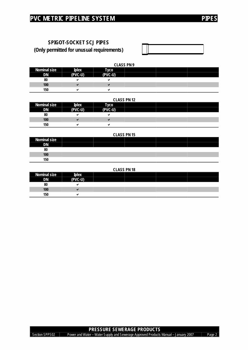
SPIGOT-SOCKET SCJ PIPES(Only permitted for unusual requirements)
CLASS PN 9Nominal size Iplex Tyco
DN (PVC-U) (PVC-U)80 a a100 a a150 a a
CLASS PN 12Nominal size Iplex Tyco
DN (PVC-U) (PVC-U)80 a a100 a a150 a a
CLASS PN 15Nominal size
DN80100150
CLASS PN 18Nominal size Iplex
DN (PVC-U)80 a100 a150 a
PVC METRIC PIPELINE SYSTEM DI BENDS
PRESSURE SEWERAGE PRODUCTSSection SPPS02 Power and Water – Water Supply and Sewerage Approved Products Manual – January 2007 Page 3
DI BENDS
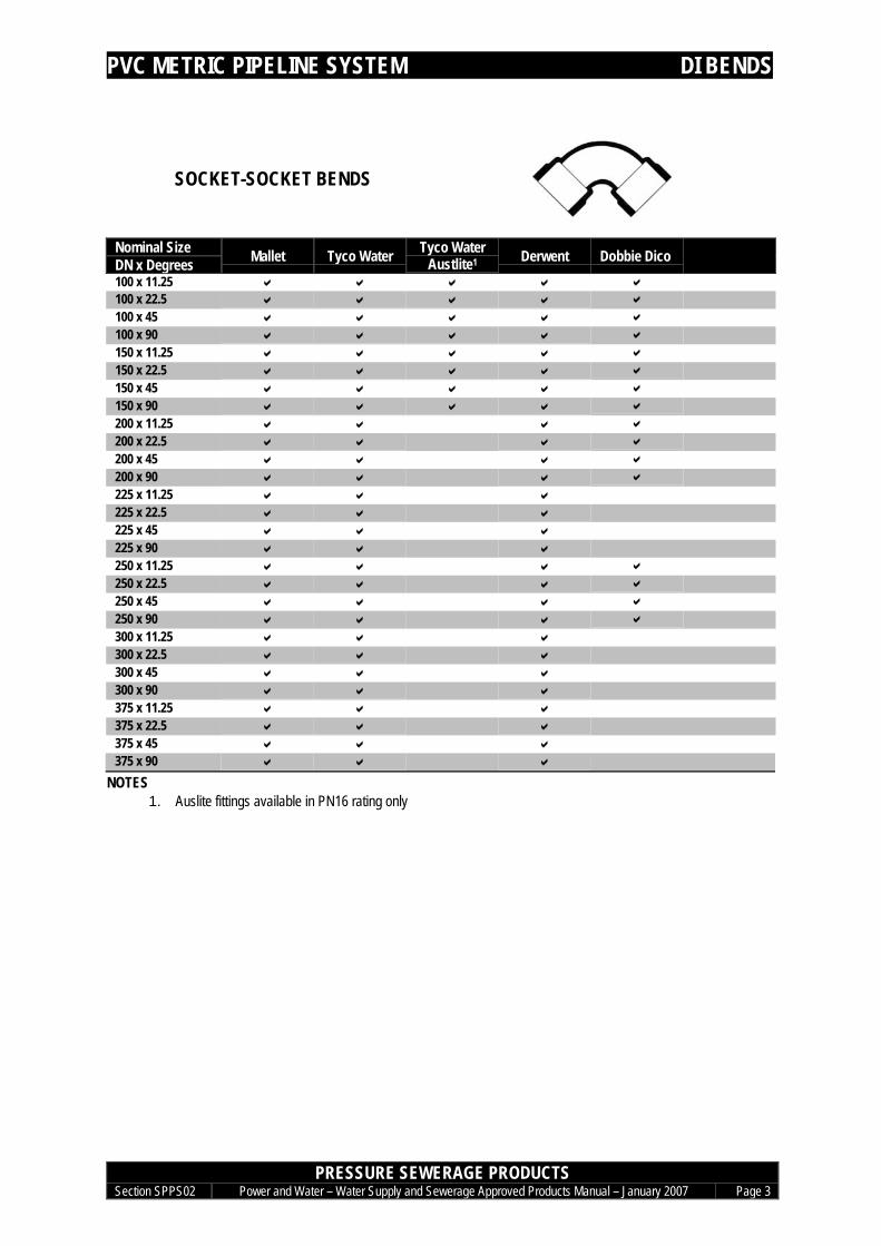
SOCKET-SOCKET BENDS
Nominal SizeDN x Degrees Mallet Tyco Water Tyco Water
Austlite1 Derwent Dobbie Dico100 x 11.25 a a a a a100 x 22.5 a a a a a100 x 45 a a a a a100 x 90 a a a a a150 x 11.25 a a a a a150 x 22.5 a a a a a150 x 45 a a a a a150 x 90 a a a a a200 x 11.25 a a a a200 x 22.5 a a a a200 x 45 a a a a200 x 90 a a a a225 x 11.25 a a a225 x 22.5 a a a225 x 45 a a a225 x 90 a a a250 x 11.25 a a a a250 x 22.5 a a a a250 x 45 a a a a250 x 90 a a a a300 x 11.25 a a a300 x 22.5 a a a300 x 45 a a a300 x 90 a a a375 x 11.25 a a a375 x 22.5 a a a375 x 45 a a a375 x 90 a a a
NOTES1. Auslite fittings available in PN16 rating only

PVC METRIC PIPELINE SYSTEM DI TEES
PRESSURE SEWERAGE PRODUCTSSection SPPS02 Power and Water – Water Supply and Sewerage Approved Products Manual – January 2007 Page 4
DI TEES
SOCKET-SOCKET-FLANGE SCOUR TEES
Nominal SizeDN x DN x dn Mallet Tyco Water Derwent150 x 150 x 80 a a a200 x 200 x 80 a a a225 x 225 x 100 a a a250 x 250 x 100 a a a300 x 300 x 100 a a a375 x 375 x 150 a a a
PVC METRIC PIPELINE SYSTEM DI CONNECTORS
PRESSURE SEWERAGE PRODUCTSSection SPPS02 Power and Water – Water Supply and Sewerage Approved Products Manual – January 2007 Page 5
DI CONNECTORS
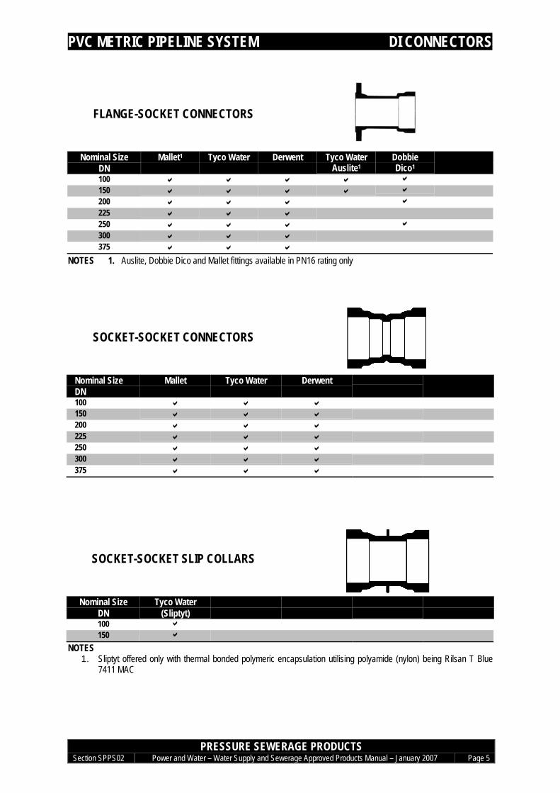
FLANGE-SOCKET CONNECTORS
Nominal SizeDN
Mallet1 Tyco Water Derwent Tyco WaterAuslite1
DobbieDico1
100 a a a a a150 a a a a a
200 a a a a
225 a a a250 a a a a
300 a a a375 a a a
NOTES 1. Auslite, Dobbie Dico and Mallet fittings available in PN16 rating only
SOCKET-SOCKET CONNECTORS
Nominal SizeDN
Mallet Tyco Water Derwent
100 a a a150 a a a200 a a a225 a a a250 a a a300 a a a375 a a a
SOCKET-SOCKET SLIP COLLARS
Nominal Size Tyco WaterDN (Sliptyt)100 a150 a
NOTES1. Sliptyt offered only with thermal bonded polymeric encapsulation utilising polyamide (nylon) being Rilsan T Blue
7411 MAC
POLYVINYL CHLORIDE PIPELINE SYSTEM END SEALS
PRESSURE SEWERAGE PRODUCTSSection SPPS02 Power and Water – Water Supply and Sewerage Approved Products Manual – January 2007 Page 6
END SEALS
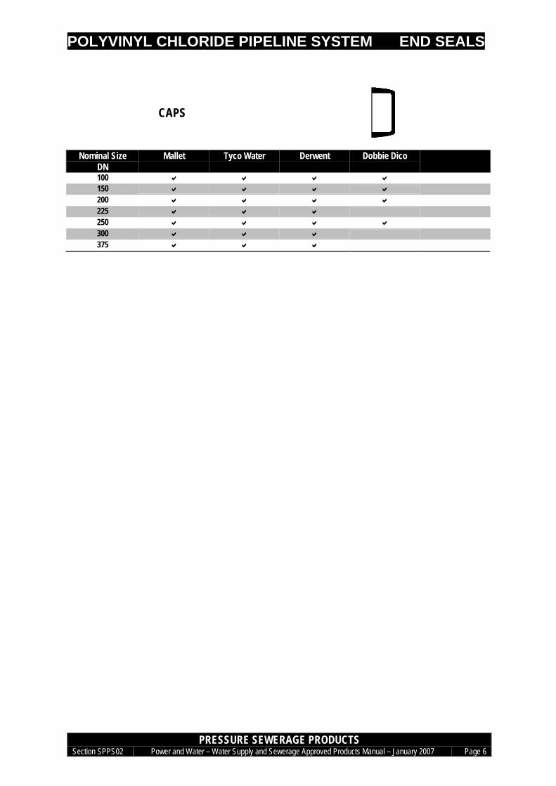
CAPS
Nominal SizeDN
Mallet Tyco Water Derwent Dobbie Dico
100 a a a a150 a a a a200 a a a a225 a a a250 a a a a300 a a a375 a a a

POLYVINYL CHLORIDE PIPELINE SYSTEM JOINT SEALS
PRESSURE SEWERAGE PRODUCTSSection SPPS02 Power and Water – Water Supply and Sewerage Approved Products Manual – January 2007 Page 7
JOINT SEALS
PVC SPIGOT TO PVC SOCKETELASTOMERIC SEALS
Nominal Size Iplex Vinidex Derwent Dobbie DicoDN (Gulf & Hultec) (Gulf & Hultec) (Gulf) (Gulf)100 a a a a150 a a a a200 a a a a225 a a a250 a a a a300 a a a375 a a a
PVC SPIGOT TO DI SOCKETELASTOMERIC SEALS
Nominal Size Mallet Tyco Water DerwentDN (Ludowici) (Gulf) (Gulf)80 a a a100 a a a
150 a a a200 a a a
225 a a a
250 a a a
300 a a a
375 a a a
FLANGE ELASTOMERIC SEALS
Nominal Size MalletDN
Tyco Water(SDQ)
)
80 a a100 a a150 a a200 a a225 a a250 a a300 a a375 a a
POLYVINYL CHLORIDE PIPELINE SYSTEM JOINT SEALS
PRESSURE SEWERAGE PRODUCTSSection SPPS02 Power and Water – Water Supply and Sewerage Approved Products Manual – January 2007 Page 8
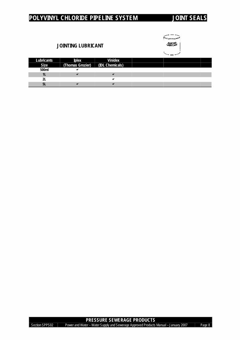
JOINTING LUBRICANT
Lubricants Iplex VinidexSize (Thomas Grozier) (IDL Chemicals)
500ml a1L a a2L a5L a a

POLYVINYL CHLORIDE PIPELINE SYSTEM SOLVENT CEMENTING
PRESSURE SEWERAGE PRODUCTSSection SPPS02 Power and Water – Water Supply and Sewerage Approved Products Manual – January 2007 Page 9
SOLVENT CEMENTING
SOLVENT CEMENT(type P – colour green)
Sizes Iplex(Bostik)
125ml a250ml a500ml a
1L a4L
PRIMING FLUID(colour pink or red)
Sizes Iplex(Bostik)
250ml a500ml a
1L a4L
POLYVINYL CHLORIDE PIPELINE SYSTEM - CORROSION PROTECTION
PRESSURE SEWERAGE PRODUCTSSection SPPS02 Power and Water – Water Supply and Sewerage Approved Products Manual – January 2007 Page 10
EXTERNAL CORROSION PROTECTION FOR DI FITTINGS
EXTERNAL CORROSION PROTECTION FOR DI FITTINGSPOLYETHYLENE SLEEVING & PETROLATUM SYSTEM
REFER TO SECTION SPO 04 CORROSION PROTECTION
Last updated Jan 2007
Water Supply and Sewerage Approved Products Manual - February 2006
Pressure Sewerage Products – Steel Pipeline System
Section SPPS 06

STEEL PIPELINE SYSTEM CONTENTS
PRESSURE SEWERAGE PRODUCTSSection SPPS 06 Power and Water – Water Supply and Sewerage Approved Products Manual – January 2007 TOC
SPECIFICATIONS ASPPS 06-S1 STEEL PIPES ASPPS 06-S2 STEEL FITTINGS C
PIPES 1TYCO ARC WELDED STEEL PIPE 1
FITTINGS 2STEEL FITTINGS TO SUIT TYCO ARC WELDED PIPE 2
EXTERNAL CORROSION PROTECTION 3

STEEL PIPELINE SYSTEM SPECIFICATIONS
PRESSURE SEWERAGE PRODUCTSSection SPPS 06 Power and Water – Water Supply and Sewerage Approved Products Manual – January 2007 Page A
SPECIFICATIONS
SPPS 06-S1 STEEL PIPESSTANDARD AS 1579:2001 Arc welded steel pipes and fittings for water and waste water
DESIGN Arc-welded steel pipes with butt-welded seams, either welded longitudinally,circumferentially or spirally. The standard defines nominal pipe sizes and the true outsidediameters for those pipes. Pipe sizes are not restricted to these nominal sizes, and uponrequest from the purchaser, can be made to any outside diameter equal to or greater than114 mm. Pipes are protected from corrosion by suitable coating and lining.
MATERIALS Pipe: Structural or analysis grade steel to AS 1594 or 3678Weld: Complete penetration butt welds to AS 1554.1 category SP. Double
sided welds are specifiedInternal lining: Cement mortar to AS 1281 using GP or SR cement and inert
aggregateCalcium aluminate cement mortar to EN14647Polyethylene coating to AS 4321Other linings may be applied as specified by the purchaser
External coating: Polyethylene coating to AS 4321Other linings may be applied as specified by the purchaser
Socket lining: Polyethylene coating to AS 4321Other linings may be applied as specified by the purchaser
Joint seal: Approved elastomer to AS 1646.1 and 1646.2 or AS 1646.3
JOINTING Joint types: Butt weld spigots (plain butt joint, butt joint with collar)Fillet weld spigot-socket (spherical slip-in joint, ball and socket joint)FlangedElastomeric sealed spigot-socketCombination elastomeric sealed spigot-socket with fillet lock weld
EFFECTIVE LENGTH 6, 9 or 12 metre lengths normally available. Longer lengths available on special request.
Dependent on pipe diameter, wall thickness and material gradeALLOWABLEOPERATING PRESSURE
PIPE SIZES USED BY CURRENTLY USED FOR NEW CONSTRUCTION NO LONGER USED FOR NEW CONSTRUCTIONPOWER AND WATER Nominal Size
DNOutside Diameter
mmNominal Size
DNOutside Diameter
mm100150225
114168257
100150525
121178559
300375450
337419508
8251100
8891206
6007501000
6608131067
MARKINGS Unique serial numberPlace of manufactureOutside diameterWall thicknessAustralian standard number i.e. AS1579Manufacturers name or registered trademarkFor hydrostatically tested pipes only, the rated pressure, in megapascals (MPa)For non-hydrostatically tested pipes, the words “Not hydrostatically tested”For pipes complying with AS/NZS 4020 ‘AS/NZS 4020’
MARKING METHOD Legibly and permanently marked on the external surface no closer than 300 mm from an end
STEEL PIPELINE SYSTEM SPECIFICATIONS
PRESSURE SEWERAGE PRODUCTSSection SPPS 06 Power and Water – Water Supply and Sewerage Approved Products Manual – January 2007 Page B
USE LIMITS Normal Portland cement mortar (GP) is not resistant to sulphuric acid that can form if H2Sdevelops in any headspace in the sewer. Sections of cement mortar lined pressure mainssubject to partially full flow could experience sulphuric acid attack if pressure main is notdesigned to avoid H2S generation (i.e. slime stripping velocity not achieved). H2S is typicallyreleased at high points on the pipeline when pressure in the line drops below 5m head.GP cement mortar should not be used if sulphate levels in the pressure sewer are likely toexceed 600 mg/litre. SR cement mortar is suitable for sulphate levels up to 6,000 mg/litre. Ifsulphate levels are likely to exceed 6,000 mg/litre or pH is likely to drop below 5.5, usecalcium aluminate cement (CAC) mortar linings.Welding of joints to be performed by qualified weldersWelded joints to have reinstatement of protection systems on siteSpecial design required for welded installations parallel to high voltage (>66kV) transmissionlinesPolyethylene coating should not be used where there is extended exposure to directsunlight.Use approved paint schemes for aboveground piping
STEEL PIPELINE SYSTEM SPECIFICATIONS
PRESSURE SEWERAGE PRODUCTSSection SPPS 06 Power and Water – Water Supply and Sewerage Approved Products Manual – January 2007 Page C
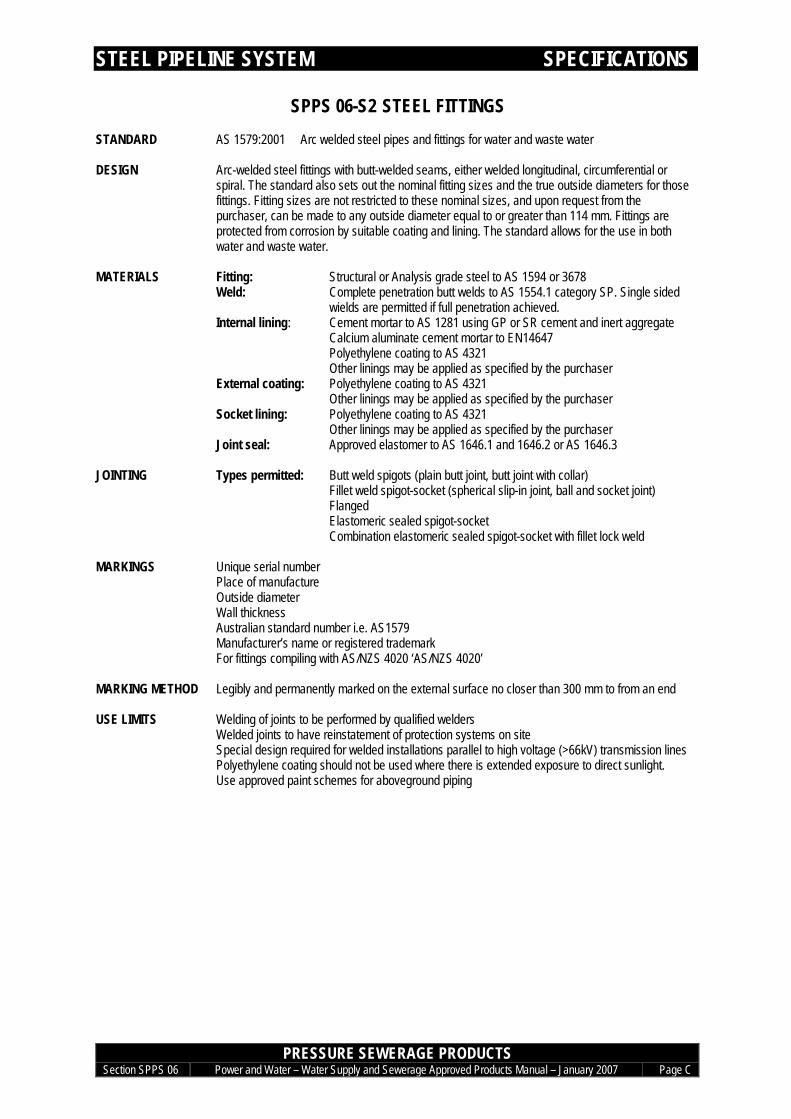
SPPS 06-S2 STEEL FITTINGSSTANDARD AS 1579:2001 Arc welded steel pipes and fittings for water and waste water
DESIGN Arc-welded steel fittings with butt-welded seams, either welded longitudinal, circumferential orspiral. The standard also sets out the nominal fitting sizes and the true outside diameters for thosefittings. Fitting sizes are not restricted to these nominal sizes, and upon request from thepurchaser, can be made to any outside diameter equal to or greater than 114 mm. Fittings areprotected from corrosion by suitable coating and lining. The standard allows for the use in bothwater and waste water.
MATERIALS Fitting: Structural or Analysis grade steel to AS 1594 or 3678Weld: Complete penetration butt welds to AS 1554.1 category SP. Single sided
wields are permitted if full penetration achieved.Internal lining: Cement mortar to AS 1281 using GP or SR cement and inert aggregate
Calcium aluminate cement mortar to EN14647Polyethylene coating to AS 4321Other linings may be applied as specified by the purchaser
External coating: Polyethylene coating to AS 4321Other linings may be applied as specified by the purchaser
Socket lining: Polyethylene coating to AS 4321Other linings may be applied as specified by the purchaser
Joint seal: Approved elastomer to AS 1646.1 and 1646.2 or AS 1646.3
JOINTING Types permitted: Butt weld spigots (plain butt joint, butt joint with collar)Fillet weld spigot-socket (spherical slip-in joint, ball and socket joint)FlangedElastomeric sealed spigot-socketCombination elastomeric sealed spigot-socket with fillet lock weld
MARKINGS Unique serial numberPlace of manufactureOutside diameterWall thicknessAustralian standard number i.e. AS1579Manufacturer’s name or registered trademarkFor fittings compiling with AS/NZS 4020 ‘AS/NZS 4020’
MARKING METHOD Legibly and permanently marked on the external surface no closer than 300 mm to from an end
USE LIMITS Welding of joints to be performed by qualified weldersWelded joints to have reinstatement of protection systems on siteSpecial design required for welded installations parallel to high voltage (>66kV) transmission linesPolyethylene coating should not be used where there is extended exposure to direct sunlight.Use approved paint schemes for aboveground piping
STEEL PIPELINE SYSTEM PIPES
PRESSURE SEWERAGE PRODUCTSSection SPPS 06 Power and Water – Water Supply and Sewerage Approved Products Manual – January 2007 Page 1
Pipes
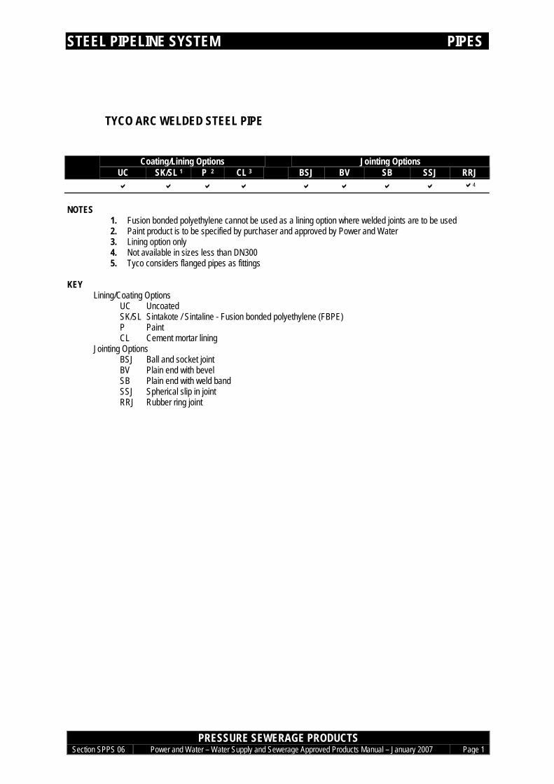
TYCO ARC WELDED STEEL PIPE
Coating/Lining Options Jointing OptionsUC SK/SL 1 P 2 CL 3 BSJ BV SB SSJ RRJa a a a a a a a a4
NOTES1. Fusion bonded polyethylene cannot be used as a lining option where welded joints are to be used2. Paint product is to be specified by purchaser and approved by Power and Water3. Lining option only4. Not available in sizes less than DN3005. Tyco considers flanged pipes as fittings
KEYLining/Coating Options
UC UncoatedSK/SL Sintakote / Sintaline - Fusion bonded polyethylene (FBPE)P PaintCL Cement mortar lining
Jointing OptionsBSJ Ball and socket jointBV Plain end with bevelSB Plain end with weld bandSSJ Spherical slip in jointRRJ Rubber ring joint

STEEL PIPELINE SYSTEM FITTINGS
PRESSURE SEWERAGE PRODUCTSSection SPPS 06 Power and Water – Water Supply and Sewerage Approved Products Manual – January 2007 Page 2
Fittings
STEEL FITTINGS TO SUITTYCO ARC WELDED PIPE
Tyco Water
a
Note: Project specific approval can be sought from Power and Water to fabricate fittings, subject to:• Fabrication off-site in a suitable workshop• Agreed procedures for repair / reinstatement of cement mortar lining• Agreed procedures for repair / reinstatement of external coatings• Welding of joints is performed by qualified welders• Agreed procedures for non-destructive testing of welds• Structural certification by an independent engineer
STEEL PIPELINE SYSTEM CORROSION PRTECTION
PRESSURE SEWERAGE PRODUCTSSection SPPS 06 Power and Water – Water Supply and Sewerage Approved Products Manual – January 2007 Page 3
EXTERNAL CORROSION PROTECTION
EXTERNAL CORROSION PROTECTIONPOLYETHYLENE SLEEVING & PETROLATUM SYSTEM
REFER TO SECTION SPO 04 CORROSION PROTECTION

Last updated Jan 2007
Water Supply and Sewerage Approved Products Manual - February 2006
Pressure Sewerage Products – Glass Reinforced Plastic Pipeline System
Section SPPS 05

GRP PIPELINE SYSTEM CONTENTS
PRESSURE SEWERAGE PRODUCTSSection SPPS05 Power and Water – Water Supply and Sewerage Approved Products Manual – January 2007 TOC
SPECIFICATIONS ASPPS 05-S1 CENTRIFUGALLY CAST GRP PIPES ASPPS 05-S2 DUCTILE IRON FITTINGS CSPPS 05-S3 JOINT SEALS DSPPS 05-S4 JOINTING LUBRICANT EWPS 05-S5 FILAMENT WOUND GRP PIPES F
PIPES 1FILAMENT WOUND GRP PIPES 1
CLASS PN 10 1CLASS PN 16 1CLASS PN 20 1
DI BENDS 2SOCKET-SOCKET BENDS 2
DI TEES 3SOCKET-SOCKET-FLANGE SCOUR TEES 3
DI CONNECTORS 4FLANGE-SOCKET CONNECTORS 4SOCKET-SOCKET CONNECTORS 4
DI CAPS 5
JOINTING 6CC GRP PIPE SYMMETRICAL COUPLINGS 6GRP SPIGOT- DI SOCKET ELASTOMERIC SEALS 7DI FLANGE ELASTOMERIC SEALS 7JOINTING LUBRICANT 7
EXTERNAL CORROSION PROTECTION FOR DI FITTINGS 8
GRP PIPELINE SYSTEM SPECIFICATIONS
PRESSURE SEWERAGE PRODUCTSSection SPPS05 Power and Water – Water Supply and Sewerage Approved Products Manual – January 2007 Page A
SPECIFICATIONS
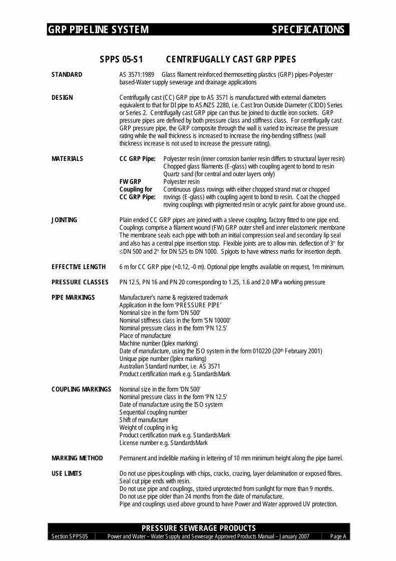
SPPS 05-S1 CENTRIFUGALLY CAST GRP PIPESSTANDARD AS 3571:1989 Glass filament reinforced thermosetting plastics (GRP) pipes-Polyester
based-Water supply sewerage and drainage applications
DESIGN Centrifugally cast (CC) GRP pipe to AS 3571 is manufactured with external diametersequivalent to that for DI pipe to AS/NZS 2280, i.e. Cast Iron Outside Diameter (CIOD) Seriesor Series 2. Centrifugally cast GRP pipe can thus be joined to ductile iron sockets. GRPpressure pipes are defined by both pressure class and stiffness class. For centrifugally castGRP pressure pipe, the GRP composite through the wall is varied to increase the pressurerating while the wall thickness is increased to increase the ring-bending stiffness (wallthickness increase is not used to increase the pressure rating).
CC GRP Pipe: Polyester resin (inner corrosion barrier resin differs to structural layer resin)Chopped glass filaments (E-glass) with coupling agent to bond to resinQuartz sand (for central and outer layers only)Polyester resin
MATERIALS
FW GRPCoupling forCC GRP Pipe:
Continuous glass rovings with either chopped strand mat or choppedrovings (E-glass) with coupling agent to bond to resin. Coat the choppedroving couplings with pigmented resin or acrylic paint for above ground use.
JOINTING Plain ended CC GRP pipes are joined with a sleeve coupling, factory fitted to one pipe end.Couplings comprise a filament wound (FW) GRP outer shell and inner elastomeric membraneThe membrane seals each pipe with both an initial compression seal and secondary lip sealand also has a central pipe insertion stop. Flexible joints are to allow min. deflection of 3° for≤DN 500 and 2° for DN 525 to DN 1000. Spigots to have witness marks for insertion depth.
EFFECTIVE LENGTH 6 m for CC GRP pipe (+0.12, -0 m). Optional pipe lengths available on request, 1m minimum.
PRESSURE CLASSES PN 12.5, PN 16 and PN 20 corresponding to 1.25, 1.6 and 2.0 MPa working pressure
PIPE MARKINGS Manufacturer’s name & registered trademarkApplication in the form ‘PRESSURE PIPE’Nominal size in the form ‘DN 500’Nominal stiffness class in the form ‘SN 10000’Nominal pressure class in the form ‘PN 12.5’Place of manufactureMachine number (Iplex marking)Date of manufacture, using the ISO system in the form 010220 (20th February 2001)Unique pipe number (Iplex marking)Australian Standard number, i.e. AS 3571Product certification mark e.g. StandardsMark
COUPLING MARKINGS Nominal size in the form ‘DN 500’Nominal pressure class in the form ‘PN 12.5’Date of manufacture using the ISO systemSequential coupling numberShift of manufactureWeight of coupling in kgProduct certification mark e.g. StandardsMarkLicense number e.g. StandardsMark
MARKING METHOD Permanent and indelible marking in lettering of 10 mm minimum height along the pipe barrel.
USE LIMITS Do not use pipes/couplings with chips, cracks, crazing, layer delamination or exposed fibres.Seal cut pipe ends with resin.Do not use pipe and couplings, stored unprotected from sunlight for more than 9 months.Do not use pipe older than 24 months from the date of manufacture.Pipe and couplings used above ground to have Power and Water approved UV protection.

GRP PIPELINE SYSTEM SPECIFICATIONS
PRESSURE SEWERAGE PRODUCTSSection SPPS05 Power and Water – Water Supply and Sewerage Approved Products Manual – January 2007 Page B
Do not use in ground conditions having low stiffness, e.g. tidal zonesDo not use where ground is unacceptably contaminated with organic compounds.Use under railways only with an encasing pipe.Combined max. steady state and surge pressure not to exceed the working pressure rating.Apply manufacturer’s rerating factors for surge events of more than 105 over the service life.

GRP PIPELINE SYSTEM SPECIFICATIONS
PRESSURE SEWERAGE PRODUCTSSection SPPS05 Power and Water – Water Supply and Sewerage Approved Products Manual – January 2007 Page C
SPPS 05-S2 DUCTILE IRON FITTINGSSTANDARD AS/NZS 2280:2004Ductile iron pressure pipes and fittings
AS/NZS 4087:2004Metallic Flanges for waterworks purposes
DESIGN Ductile iron fittings to the Australian Standard have dimensions based on imperial sizing. As aresult, the metric nominal sizing relates only roughly to the internal diameter after cement lining.
MATERIALS Fitting: Spheroidal graphite cast iron to AS 1831(commonly known as ductile iron)– manufactured from scrap ductile iron, steel, ferrosilicon, coke, limestoneand magnesium
Internal lining: Thermal bonded polymer to AS/NZS 4158External coating: Thermal bonded polymer to AS/NZS 4158
Other coatings may be consideredJoint seal: Elastomer type to AS 1646
JOINTING Socket: Sockets with grooves to capture elastomeric seals. Sockets and seals ofproprietary profile designs, (e.g. Tyton, Griptite). Allowable minimum jointdeflections of 2.5° for DN 300-600 and 1° for DN 750. Jointing lugs on 90°and 45° bends for sizes DN 200 and greater.
Spigot: End to be chamfered over 10 to 20 mm at approximately 20° to pipe barrel.Jointing lugs on 90° and 45° bends for sizes DN 200 and greater.
Flange: Integral flanges to AS 4087 figure B5 for PN16 and figure B6 for PN35.1.5mm and 3mm flat elastomeric full face gasket to AS 4087 for PN16 andPN35 - Appendix C, Table C1
ALLOWABLEOPERATINGPRESSURE
PN16:PN35:
1.6 MPa3.5 MPa
MARKINGS Manufacturer’s name or mark cast onNominal sizeDuctile or DI moulded in raised formWhere applicable, the angle of the bend cast onThe standard designation AS/NZS 2280Product certification mark, e.g. StandardsMarkTraceability codePlace of manufacture (may be incorporated in traceability code)
MARKING METHOD Clearly & indelibly marked on the fitting. Lettering heights & raised height not specified in AS/NZS2280.
GRP PIPELINE SYSTEM SPECIFICATIONS
PRESSURE SEWERAGE PRODUCTSSection SPPS05 Power and Water – Water Supply and Sewerage Approved Products Manual – January 2007 Page D
SPPS 05-S3 JOINT SEALSSTANDARD AS 1646: 2000 Elastomeric seals for waterworks purposes
AS 4087: 2004 Metallic flanges for waterworks purposes
SEALING DESIGN Joint seals are to be of elastomeric compounds comprising suitable polymers. The elastomershave performance properties, which deteriorate with time and as such the design of the seal’sprofile and the compounding of the elastomer needs to ensure long term sealing of the joint. Theelastomer properties affecting long term sealing performance are hardness, rate of compressionstress relaxation, water absorption, resistance to ageing, resistance to chemicals and resistanceto microbiological deterioration.
COMPOUNDMATERIALS
Polymer forspigot-socketrings:
Ethylene propylene diene monomer (EPDM), 40% minimum volume ofcompound for IRHD of ≥55<85Styrene Butadiene Rubber (SBR), 60% minimum volume of compoundfor IRHD of ≥55<85
Polymer for flangegaskets:
Ethylene propylene diene monomer (EPDM), 30% minimum volume ofcompound for IRHD of ≥35<55 or 40% minimum volume of compoundfor IRHD ≥55≤65Styrene Butadiene Rubber (SBR), 50% minimum volume of compoundfor IRHD of ≥35<55 or ≥55≤65
Antidegradant: For EPDM: Not requiredFor SBR: Based on the combined antioxidant-antiozonant N-(1,3-dimethyl-butyl)-N’-phenyl-p-phenylene diamine with a concentration(m/m) of not less than 1.5 parts per hundred of polymer.
Protective wax: For EPDM: Not requiredFor SBR: Wax with a melting point of not less than 57°C andconcentration (m/m) not greater than 3.0 parts per hundred of polymer.
Filler: Carbon blackCopper &manganese:
For EPDM: Not applicableFor SBR: Not greater than 0.0008% copper and 0.0005% manganese
MARKINGS Rings: Manufacturer’s identification markCavity number, if applicableNominal size or nominal internal and cord diameters as appropriateYear of manufacture, e.g. 00 to represent year 2000Standard designation where the elastomeric ring is certified to AS 1646.
MARKING METHODS Embossing with lettering 3 ± 1 mm high and 0.3 ± 0.1 mm proud of the surface; orVulcanised transfer or permanent ink with lettering 3.5 ± 1.5 mm.
EPDM: GreenMarking colour:SBR: Blue
ELASTOMER TYPEIDENTIFICATION
Marking method: Continuous durable stripe of width 3.5 ± 1.5 mm; orDurable flash or dot of 6 mm minimum dimension
STORAGE • Do not store seals in a room with any equipment capable of generating ozone (e.g. mercuryvapour lamps, electric motors, high voltage equipment).
• Store in a relaxed condition free from tension, compression or other deformation.• Seal temperature not to exceed 35°C and preferably not above 25°C or less than 5°C.
USE LIMITS Do not use elastomeric seals removed from packaging for more than 3 monthsDo not use elastomeric seals older than 18 months from date of manufacture unless suppliercan demonstrate that seals have been stored in a cool, controlled environment.Do not use SBR elastomeric seals more than 3 years from date of manufactureDo not use EPDM elastomeric seals more than 6 years from date of manufactureDo not use SBR seals that have been stored unprotected from sunlight for more than 7 daysDo not use elastomeric seals that have been in contact with chemicals, e.g. solvents (petrol).
GRP PIPELINE SYSTEM SPECIFICATIONS
PRESSURE SEWERAGE PRODUCTSSection SPPS05 Power and Water – Water Supply and Sewerage Approved Products Manual – January 2007 Page E
SPPS 05-S4 JOINTING LUBRICANT
STANDARD None
DESIGN Jointing lubricant is required to achieve the following:
• Provide sufficient lubrication to prevent damage to joint seals or surfaces on jointing.• Enable correctly configured jointing when using jointing methods recommended by the
pipe or fitting manufacturer.• Not affect the elastomer or pipe or fitting materials.• Remain an effective lubricant under wet conditions.• Not be hazardous to handle and be able to be applied by hand.• Be completely soluble in water.• Be able to be removed under standard flushing arrangements for commissioning.
MATERIALS Lubricant: Water based emulsion
CONTAINER MARKINGS Manufacturer’s name or trademarkProprietary name of joint seal with which the lubricant can be used.The words ‘Jointing Lubricant’ or ‘Joint Lubricant’.Date of manufacture.Date of expiry for use.The specification to which it complies.The WaterMark or other mark to certify compliance with the specification.Instructions for use of lubricant.
USE LIMITS Do not use where past expiry date.
GRP PIPELINE SYSTEM SPECIFICATIONS
PRESSURE SEWERAGE PRODUCTSSection SPPS05 Power and Water – Water Supply and Sewerage Approved Products Manual – January 2007 Page F
WPS 05-S5 FILAMENT WOUND GRP PIPESSTANDARD ISO 10639 Plastic Piping Systems for Pressure and Non-Pressure Water Supply – Glass-
Reinforced Thermosetting Plastics (GRP) Systems Based on Unsaturated Polyester (UP)Resin
DESIGN GRP pipe manufactured with external diameters equivalent to that for DI pipe to AS/NZS2280, i.e. Cast Iron Outside Diameter (CIOD) Series or Series 2 GRP pressure pipes aredefined by both pressure class and stiffness class.
MATERIALS GRP Pipe: Polyester resinChopped and continuous glass filaments (ECR-glass)Quartz sand (filler)
JOINTING Plain ended GRP pipes are joined with a sleeve coupling, factory fitted to one pipe end.Deflection permitted at joints varies with pipe pressure class and pipe diameter.PN10 & PN16 – 3° maximum for DN300, DN375 and DN450. 2° maximum for DN525,DN600, DN675 and DN750.PN20 – 2° maximum for DN300, DN375 and DN450. 1.5° maximum for DN525, DN600,DN675 and DN750.
External diameter of the pipe may vary along its length. Pipes with external diameter withintolerances for full length to be marked as ‘alignment pipes’ and may be used on-site as cutpipe. Sealing of cut ends of pipe not required.
EFFECTIVE LENGTH 6 m. Optional pipe lengths available on request, 1m minimum.
PRESSURE CLASSES PN 10, PN 16 and PN 20 corresponding to 1.0, 1.6 and 2.0 MPa working pressure
PIPE MARKINGS Manufacturer’s name and/or logoNominal size in the form ‘DN 450’Nominal stiffness in the form ‘SN 10000’Nominal pressure class in the form ‘PN 16’Date of manufacture, using the ISO system in the form YYMMDD (eg. 000220 is20th February 2000)Batch descriptionDate of manufacture, using the ISO system in the form 000220 (20th February 2000)Unique pipe number
MARKING METHOD Permanent and indelible marking in lettering of 10 mm minimum height along the pipe barrel.
USE LIMITS Do not use pipes/couplings with chips, cracks, crazing, layer delamination or exposed fibres.Only tap GRP pipes in accordance with manufacturer’s instructionsDo not use pipe and couplings, stored unprotected from sunlight for more than 9 months.Do not use pipe older than 24 months from the date of manufacture.Pipe and couplings used above ground to have Power and Water approved UV protection.Do not use in ground conditions having low stiffness, e.g. tidal zonesDo not use where ground is unacceptably contaminated with organic compounds.Use under railways only with an encasing pipe.Combined max. steady state and surge pressure not to exceed the working pressure rating.For pumped systems, fatigue allowances must be made (refer to manufacturer)

GRP PIPELINE SYSTEM PIPES
PRESSURE SEWERAGE PRODUCTSSection SPPS05 Power and Water – Water Supply and Sewerage Approved Products Manual – January 2007 Page 1
PIPES
FILAMENT WOUND GRP PIPESCOMPLETE WITH COUPLING
(STIFFNESS CLASS SN 10000)
CLASS PN 10Nominal size Iplex
DN (Flowtite)300 a375 a450 a525 a600 a675 a750 a
CLASS PN 16Nominal size Iplex
DN (Flowtite)300 a375 a450 a525 a600 a675 a750 a
CLASS PN 20Nominal size Iplex
DN (Flowtite)300 a375 a450 a525 a600 a675 a750 a

GRP PIPELINE SYSTEM DI BENDS
PRESSURE SEWERAGE PRODUCTSSection SPPS05 Power and Water – Water Supply and Sewerage Approved Products Manual – January 2007 Page 2
DI BENDS
SOCKET-SOCKET BENDS
Nominal sizeDN x degrees Mallet Tyco Water Derwent300 x 11.25 a a a300 x 22.5 a a a300 x 45 a a a300 x 90 a a a375 x 11.25 a a a375 x 22.5 a a a375 x 45 a a a375 x 90 a a a450 x 11.25 a a a450 x 22.5 a a a450 x 45 a a a450 x 90 a a a525 x 11.25525 x 22.5525 x 45525 x 90600 x 11.25 a a a600 x 22.5 a a a600 x 45 a a a600 x 90 a a a675 x 11.25675 x 22.5675 x 45675 x 90750 x 11.25 a a750 x 22.5 a a750 x 45 a a750 x 90 a a
GRP PIPELINE SYSTEM DI TEES
PRESSURE SEWERAGE PRODUCTSSection SPPS05 Power and Water – Water Supply and Sewerage Approved Products Manual – January 2007 Page 3
DI TEES
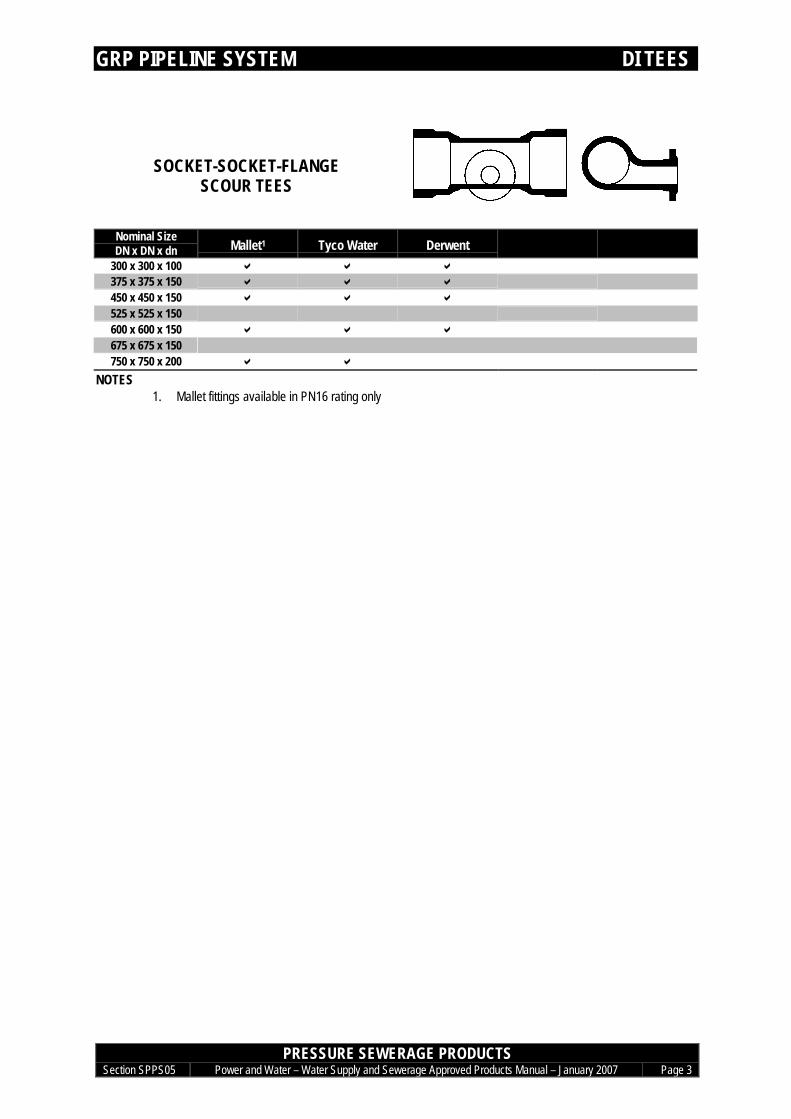
SOCKET-SOCKET-FLANGESCOUR TEES
Nominal SizeDN x DN x dn Mallet1 Tyco Water Derwent
300 x 300 x 100 a a a375 x 375 x 150 a a a450 x 450 x 150 a a a525 x 525 x 150600 x 600 x 150 a a a675 x 675 x 150750 x 750 x 200 a a
NOTES1. Mallet fittings available in PN16 rating only

GRP PIPELINE SYSTEM DI CONNECTORS
PRESSURE SEWERAGE PRODUCTSSection SPPS05 Power and Water – Water Supply and Sewerage Approved Products Manual – January 2007 Page 4
DI CONNECTORS
FLANGE-SOCKET CONNECTORS
Nominal SizeDN
Mallet1 Tyco Water Derwent
300 a a a375 a a a450 a a a525600 a a a675750 a a
NOTES1. Mallet fittings available in PN16 rating only
SOCKET-SOCKET CONNECTORS
Nominal SizeDN
Mallet Tyco Water Derwent
300 a a a375 a a a450 a a a525600 a a a675750 a a
GRP PIPELINE SYSTEM DI CAPS
PRESSURE SEWERAGE PRODUCTSSection SPPS05 Power and Water – Water Supply and Sewerage Approved Products Manual – January 2007 Page 5
DI CAPS
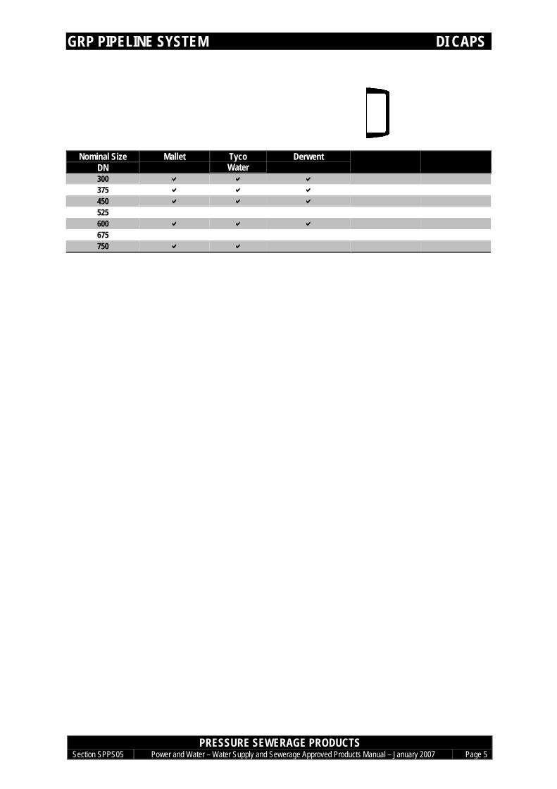
CAPS
Nominal SizeDN
Mallet TycoWater
Derwent
300 a a a375 a a a450 a a a525600 a a a675750 a a

GRP PIPELINE SYSTEM JOINTING
PRESSURE SEWERAGE PRODUCTSSection SPPS05 Power and Water – Water Supply and Sewerage Approved Products Manual – January 2007 Page 6
JOINTING
CC GRP PIPESYMMETRICAL COUPLINGS
Nominal Size IplexDN (Flowtite)300 a(L= 270)375 a(L= 270)450 a(L= 270)525 a(L= 270)600 a(L= 330)675 a(L= 330)750 a(L= 330)
CC GRP PIPE SYMMETRICAL COUPLINGS PN 16
GRP PIPELINE SYSTEM JOINTING
PRESSURE SEWERAGE PRODUCTSSection SPPS05 Power and Water – Water Supply and Sewerage Approved Products Manual – January 2007 Page 7
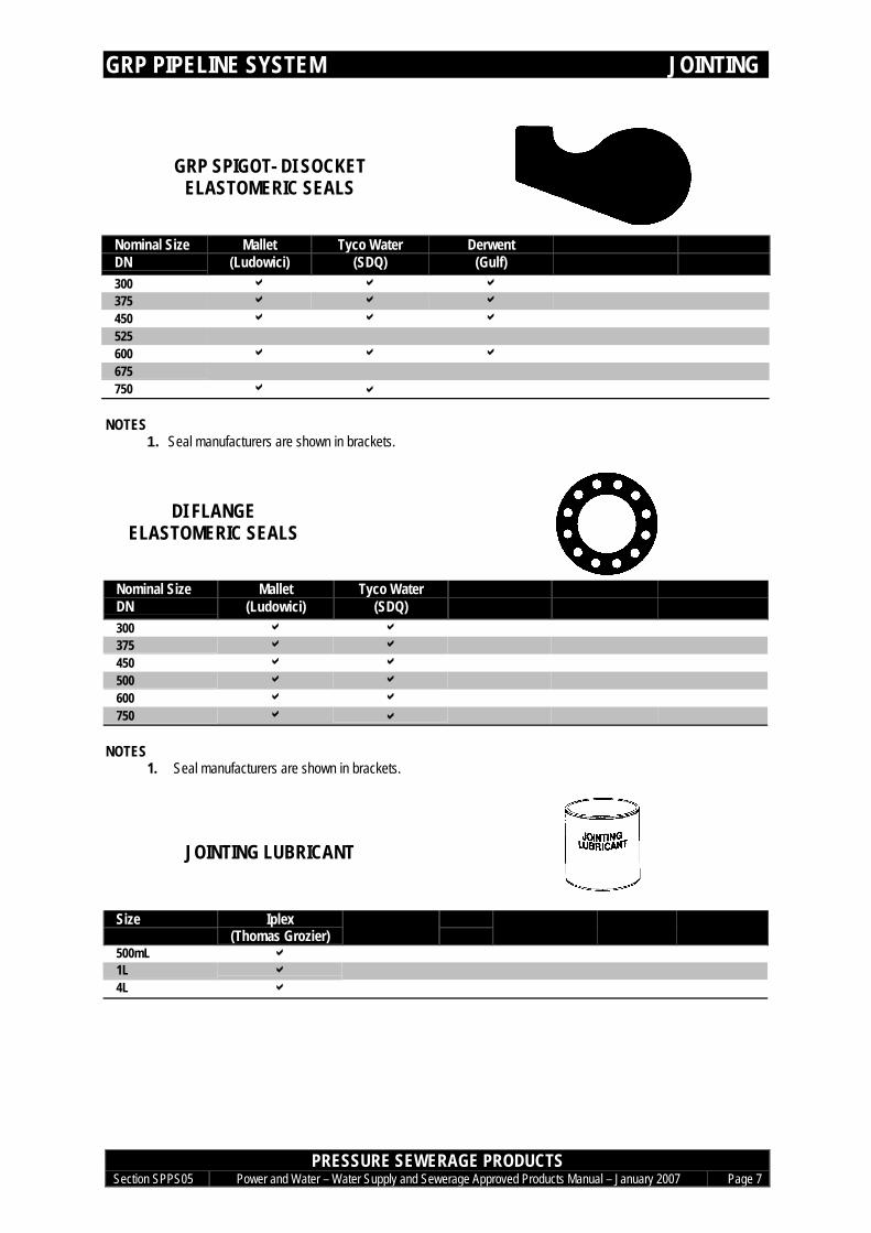
GRP SPIGOT- DI SOCKETELASTOMERIC SEALS
Nominal Size Mallet Tyco Water DerwentDN (Ludowici) (SDQ) (Gulf)300 a a a
375 a a a
450 a a a
525600 a a a
675750 a a
NOTES1. Seal manufacturers are shown in brackets.
DI FLANGE SEAL
DI FLANGEELASTOMERIC SEALS
Nominal Size Mallet Tyco WaterDN (Ludowici) (SDQ)300 a a
375 a a
450 a a
500 a a
600 a a
750 a a
NOTES1. Seal manufacturers are shown in brackets.
JOINTING LUBRICANT
Size Iplex(Thomas Grozier)
500mL a1L a
4L a

GRP PIPELINE SYSTEM CORROSION PROTECTION
PRESSURE SEWERAGE PRODUCTSSection SPPS05 Power and Water – Water Supply and Sewerage Approved Products Manual – January 2007 Page 8
EXTERNAL CORROSION PROTECTION FOR DI FITTINGS
EXTERNAL CORROSION PROTECTION FOR DI FITTINGSPOLYETHYLENE SLEEVING & PETROLATUM SYSTEM
REFER TO SECTION SPO 04 CORROSION PROTECTION