appendix c: hydraulics and hydrology - cloud object … c: hydraulics and hydrology ... impacts and...
TRANSCRIPT
Appendix C: Hydraulics and Hydrology
Fargo Moorhead Metropolitan Area
Flood Risk Management Project
Reach 7, Stations 683+00 to 755+00
Engineering and Design Phase
Doc Version: Preliminary Engineering Report (PER)
12 June 2015

Fargo Moorhead Metropolitan Area Preliminary Engineering Report Flood Risk Management Project Reach 7 Appendix C: Hydraulics and Hydrology
This page is intentionally left blank

Fargo Moorhead Metropolitan Area Preliminary Engineering Report Flood Risk Management Project Reach 7 Appendix C: Hydraulics and Hydrology
C-i
Appendix C: Hydraulics and Hydrology
Table of Contents
C.1 PROJECT DESCRIPTION ....................................................................................................................... C-1
C.1.1 Overview ...................................................................................................................................... C-1
C.1.2 Design Event ................................................................................................................................ C-2
C.1.3 Design Flows ................................................................................................................................ C-4
C.2 REACH 7 FEATURES .............................................................................................................................. C-6
C.2.1 Diversion Channel ........................................................................................................................ C-6
C.2.2 Maple River Aqueduct ................................................................................................................. C-9
C.2.3 Maple River Flow Split ............................................................................................................... C-10
C.2.4 Spillway ...................................................................................................................................... C-10
C.2.5 Engineered Channel ................................................................................................................... C-11
C.2.6 Left Bank EMB Gap..................................................................................................................... C-12
C.2.7 Maple River Ice Retention Structure ......................................................................................... C-12
C.2.8 Controlling Elevations and Dimensions ..................................................................................... C-13
C.3 FURTHER DESIGN GUIDELINES ......................................................................................................... C-15
Figures Figure C-1 Location Map – Reach 7............................................................................................................ C-6
Figure C-2 Typical Reach 7 Diversion Cross Section ................................................................................... C-6
Figure C-3 Diversion Feature Profile and Water Surface Profile Information ........................................... C-8
Tables Table C- 1 Summary of Historic and Synthetic Discharges at Fargo, North Dakota .................................. C-1

Fargo Moorhead Metropolitan Area Preliminary Engineering Report Flood Risk Management Project Reach 7 Appendix C: Hydraulics and Hydrology
C-ii
Table C- 2 Diversion Flows ......................................................................................................................... C-5
Table C- 3. Controlling Elevations ............................................................................................................ C-13
Table C- 4. Required Dimensions ............................................................................................................. C-13
References MFR – 001. FMM – Levees and Excavated Material Berms along the Diversion Channel, USACE. June 2012.
MFR – 002. FMM –Diversion Channel and Low Flow Design. USACE. DRAFT. June 2012.
Outlet Structure Selection and Design Documentation. USACE. June 2012.
EM 1110-2-1601 - Engineering and Design - Hydraulic Design of Flood Control Channels. Original document - 1 July 1991. Change 1 - 30 June 1994.
Research Report No. 24 – United States Department of the Interior Bureau of Reclamation
Aadland, L.P. 2010. Reconnecting Rivers: Natural Channel Design in Dam Removals and Fish Passage. Division of Ecological Resources Stream Habitat Program, Minnesota Department of Natural Resources, St. Paul, MN.
AWD-0005, Local Drainage Plan. Moore Engineering, Inc. November 2012.
Evaluating Alternatives for the Rush and Lower Rush Connections to the Main Diversion Channel. Barr Engineering, March 2012.
Fischenich, J.C. (1997). “Hydraulic impacts of riparian vegetation; Summary of the literature,” Technical Report EL-97-9, U.S. Army Engineer Waterways Experiment Station, Vicksburg, MS.
Attachments Attachment 01 – Hydraulic Investigation Report
Attachment 02 – Draft Hydraulic Optimization Report
Attachment 03 – Spillway Type Report

Fargo Moorhead Metropolitan Area Preliminary Engineering Report Flood Risk Management Project Reach 7 Appendix C: Hydraulics and Hydrology
C-iii
This page is intentionally left blank
Fargo Moorhead Metropolitan Area Preliminary Engineering Report Flood Risk Management Project Reach 7 Appendix C: Hydraulics and Hydrology
C-1
Appendix C: Hydraulics and Hydrology
C.1 PROJECT DESCRIPTION
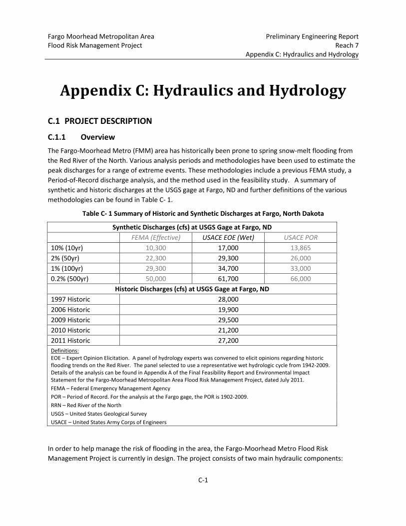
C.1.1 Overview The Fargo-Moorhead Metro (FMM) area has historically been prone to spring snow-melt flooding from the Red River of the North. Various analysis periods and methodologies have been used to estimate the peak discharges for a range of extreme events. These methodologies include a previous FEMA study, a Period-of-Record discharge analysis, and the method used in the feasibility study. A summary of synthetic and historic discharges at the USGS gage at Fargo, ND and further definitions of the various methodologies can be found in Table C- 1.
Table C- 1 Summary of Historic and Synthetic Discharges at Fargo, North Dakota
Synthetic Discharges (cfs) at USGS Gage at Fargo, ND
FEMA (Effective) USACE EOE (Wet) USACE POR 10% (10yr) 10,300 17,000 13,865 2% (50yr) 22,300 29,300 26,000 1% (100yr) 29,300 34,700 33,000 0.2% (500yr) 50,000 61,700 66,000
Historic Discharges (cfs) at USGS Gage at Fargo, ND 1997 Historic 28,000 2006 Historic 19,900 2009 Historic 29,500 2010 Historic 21,200 2011 Historic 27,200 Definitions: EOE – Expert Opinion Elicitation. A panel of hydrology experts was convened to elicit opinions regarding historic flooding trends on the Red River. The panel selected to use a representative wet hydrologic cycle from 1942-2009. Details of the analysis can be found in Appendix A of the Final Feasibility Report and Environmental Impact Statement for the Fargo-Moorhead Metropolitan Area Flood Risk Management Project, dated July 2011. FEMA – Federal Emergency Management Agency POR – Period of Record. For the analysis at the Fargo gage, the POR is 1902-2009. RRN – Red River of the North USGS – United States Geological Survey USACE – United States Army Corps of Engineers
In order to help manage the risk of flooding in the area, the Fargo-Moorhead Metro Flood Risk Management Project is currently in design. The project consists of two main hydraulic components:
Fargo Moorhead Metropolitan Area Preliminary Engineering Report Flood Risk Management Project Reach 7 Appendix C: Hydraulics and Hydrology
C-2
1. An upstream staging area and earthen embankment to temporarily detain the water during large flood events on the Red and Wild Rice Rivers. Gated control structures will be included on each of the two rivers to regulate the flow through the Fargo-Moorhead community.
2. A diversion channel to convey flood flows from the staging area, the Sheyenne, Maple, Rush and Lower Rush Rivers, and various drains around the community. The diversion channel will reconnect with the Red River downstream of Fargo-Moorhead in an area where the floodplain is several miles wide.
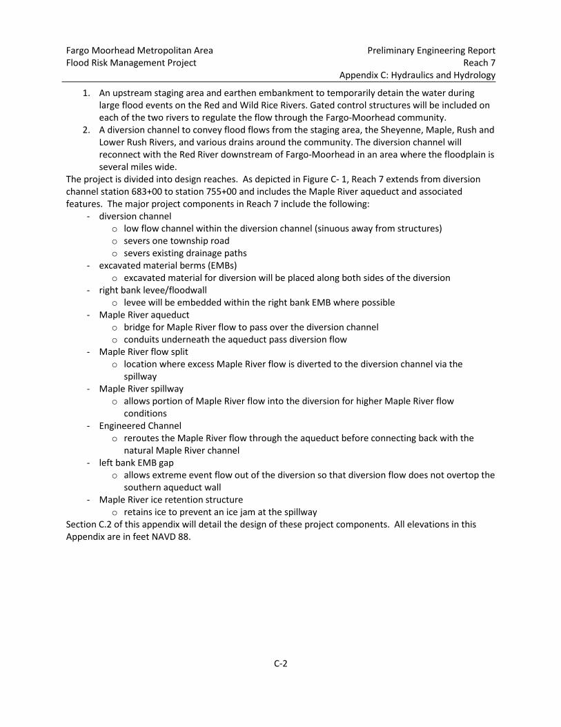
The project is divided into design reaches. As depicted in Figure C- 1, Reach 7 extends from diversion channel station 683+00 to station 755+00 and includes the Maple River aqueduct and associated features. The major project components in Reach 7 include the following:
- diversion channel o low flow channel within the diversion channel (sinuous away from structures) o severs one township road o severs existing drainage paths
- excavated material berms (EMBs) o excavated material for diversion will be placed along both sides of the diversion
- right bank levee/floodwall o levee will be embedded within the right bank EMB where possible
- Maple River aqueduct o bridge for Maple River flow to pass over the diversion channel o conduits underneath the aqueduct pass diversion flow
- Maple River flow split o location where excess Maple River flow is diverted to the diversion channel via the
spillway - Maple River spillway
o allows portion of Maple River flow into the diversion for higher Maple River flow conditions
- Engineered Channel o reroutes the Maple River flow through the aqueduct before connecting back with the
natural Maple River channel - left bank EMB gap
o allows extreme event flow out of the diversion so that diversion flow does not overtop the southern aqueduct wall
- Maple River ice retention structure o retains ice to prevent an ice jam at the spillway
Section C.2 of this appendix will detail the design of these project components. All elevations in this Appendix are in feet NAVD 88.

Fargo Moorhead Metropolitan Area Preliminary Engineering Report Flood Risk Management Project Reach 7 Appendix C: Hydraulics and Hydrology
C-3
Figure C- 1. Location Map – Reach 7

Fargo Moorhead Metropolitan Area Preliminary Engineering Report Flood Risk Management Project Reach 7 Appendix C: Hydraulics and Hydrology
C-4
C.1.2 Design Event
The diversion is designed for the 1% annual chance exceedance flood (1% flood), but the amount of excavation required to achieve the goals for the 1% flood design allows the diversion to function for much larger flood events. Flood events larger than the 1% flood are being investigated during the design effort to evaluate structure and levee resiliency. Design flows in the diversion were determined from the unsteady HEC-RAS modeling effort, which routes the Red River of the North balanced hydrographs and coincident tributary hydrographs described in Appendix A of the Final Feasibility Report and Environmental Impact Statement for the Fargo-Moorhead Metropolitan Area Flood Risk Management Project, dated July 2011.
C.1.3 Design Flows
Early in the design process a cursory review of flow results along the diversion resulted in using 30,000 cfs for the 1% event flow and 35,000 cfs for the 0.2% event flow for the entire reach between the Maple River aqueduct and the diversion outlet. As the design effort progressed, a detailed assessment of the flow profile along the diversion was conducted that resulted in the more detailed design flow table presented as Table C-2.
The amount of flow to be let in to the diversion at the inlet for the 1% flood, which is 20,000 cfs, was determined by investigating downstream impacts and the amount of storage needed in the upstream staging area to essentially eliminate downstream impacts. Sediment transport, geomorphic, and geotechnical considerations determined the shape of the diversion (size of low-flow channel, bottom width, and side slopes). The 1% flood flows used to size the diversion and the higher flows investigated when considering structure and levee resiliency are presented in Table C- 2. The gated diversion inlet structure will limit flow at the inlet to 20,000 cfs for floods up through the 0.2% flood. Flow in the downstream direction increases due to inflows from the tributaries and drains.
Based on modeling efforts completed so far, it is expected that flood fighting efforts will continue well beyond the 0.2% flood. While more work needs to be done regarding how the diversion inlet gates and the overflow spillway adjacent to the diversion inlet will operate during events larger than the 0.2% flood, the estimated maximum flood fight flow data provided in Table C- 2 is an estimate of how much flow would be in the diversion while flood fighting efforts exist in the flood risk reduction area.

Fargo Moorhead Metropolitan Area Preliminary Engineering Report Flood Risk Management Project Reach 7 Appendix C: Hydraulics and Hydrology
C-5
Table C- 2 Diversion Flows
DESCRIPTION 1% FLOW (cfs) 0.2% FLOW (cfs) EST. MAX.
FLOOD FIGHT FLOW (cfs)
Diversion Inlet to Sheyenne River Aqueduct 20,000 20,000 26,000
Sheyenne River Aqueduct to Cass CR 14 20,500 22,000 38,000
Cass CR 14 to Ditch 21C 20,500 22,000 40,000
Ditch 21C to Ditch Upstream of I-94 21,000 22,500 41,000
Ditch Upstream of I-94 to Drain 14 21,500 23,500 41,000
Drain 14 to Maple River Aqueduct 25,000 28,000 41,000
Maple River Aqueduct to Lower Rush River 29,000 34,000 41,000
Lower Rush River to Rush River 30,000 36,000 45,000
Rush River to Diversion Outlet 32,000 38,000 45,000
Fargo Moorhead Metropolitan Area Preliminary Engineering Report Flood Risk Management Project Reach 7 Appendix C: Hydraulics and Hydrology
C-6
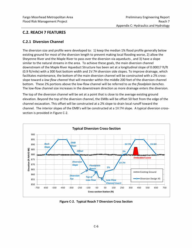
C.2. REACH 7 FEATURES C.2.1 Diversion Channel The diversion size and profile were developed to: 1) keep the median 1% flood profile generally below existing ground for most of the diversion length to prevent making local flooding worse, 2) allow the Sheyenne River and the Maple River to pass over the diversion via aqueducts , and 3) have a slope similar to the natural streams in the area. To achieve these goals, the main diversion channel downstream of the Maple River Aqueduct Structure has been set at a longitudinal slope of 0.00017 ft/ft (0.9 ft/mile) with a 300 foot bottom width and 1V:7H diversion side slopes. To improve drainage, which facilitates maintenance, the bottom of the main diversion channel will be constructed with a 2% cross-slope toward a low-flow channel that will meander within the middle 200 feet of the diversion channel bottom. These 2% portions above the low-flow channel will be referred to as the floodplain benches. The low-flow channel size increases in the downstream direction as more drainage enters the diversion.
The top of the diversion channel will be set at a point that is close to the average existing ground elevation. Beyond the top of the diversion channel, the EMBs will be offset 50 feet from the edge of the channel excavation. This offset will be constructed at a 2% slope to drain local runoff toward the channel. The interior slopes of the EMB’s will be constructed at a 1V:7H slope. A typical diversion cross-section is provided in Figure C-2.
Figure C-2. Typical Reach 7 Diversion Cross Section
850
855
860
865
870
875
880
885
890
895
900
-750 -650 -550 -450 -350 -250 -150 -50 50 150 250 350 450 550 650 750
Elev
atio
n (ft
NAV
D 88
)
Cross-section Station (ft)
Typical Diversion Cross-Section
Existing Ground
Diversion Design XS
Floodplain Bench 2%
1V:7H
EMB Slope
1V:7H
Offset 2%
Diversion Slope
Low-Flow Channel Invert
1V:6H Back Slope
Embedded Levee
Diversion Toe
Top of Low-Flow
Fargo Moorhead Metropolitan Area Preliminary Engineering Report Flood Risk Management Project Reach 7 Appendix C: Hydraulics and Hydrology
C-7
Within Reach 7, the width of the diversion channel narrows upstream of the Maple River aqueduct. The structures in Reach 7 require a number of transitions for the EMBs and the sinuous low flow channel. Recreation and maintenance traffic will be allowed across the bridge at the aqueduct, but local traffic affected by the severing of 34th Street SE will be redirected to diversion crossings upstream and downstream of Reach 7. Local drainage affected by the presence of the diversion channel will be redirected via ditches along the outside toes of the excavated material berms.
Given the existing bed profile of the Maple River, the invert of the Maple River aqueduct can’t be higher than the 881.00 elevation listed in Table C-3. This results in conduits under the Maple River aqueduct that aren’t as tall as what would be ideal. After feasibility it was determined that the diversion cross-section should have a larger low flow channel for sediment transport reasons and should have a transverse slope of 2% that results in drainage towards the low flow channel (see Figure C-1). Using the Maple River aqueduct as the pivot point so that already shorter than desired conduits were not made any shorter, the longitudinal channel slope was increased from 0.8 ft/mile to 0.9 ft/mile to produce the desired profile for the 1% event given the change in the diversion cross-section. It was also determined that the low flow channel should have some sinuosity. The study of the low flow channel sinuosity is provided in the hydraulic appendix. Design of conduit entry, pier shape, and conduit number is detailed in Sections 3.1 and 3.2 of the Draft Hydraulic Optimization Report. Wingwalls will direct the flow of the diversion channel both upstream and downstream of the conduits. Radial wingwalls, 45 degree, and 90 degree wingwalls have been studied upstream of the aqueduct. Straight and 90 degree wingwalls have been studied downstream of the aqueduct. The 90 degree wingwalls produced adverse hydraulic flow patterns both upstream and downstream of the aqueduct. Therefore, 90 degree wingwalls were not desired. The current design upstream of the aqueduct uses a 45 degree wingwall geometry. The radial wingwalls may still be considered for final design if it can be shown to be cost effective. The wingwalls downstream of the aqueduct were kept straight. Analysis of the 45 and 90 degree wingwalls are detailed in Sections 3.3 and 3.4 of the Draft Hydraulic Optimization Report. Radial wingwalls were studied in the Hydraulic Investigation Report. Downstream of the Maple River aqueduct , the diversion toe to diversion toe width (bottom width) was determined to be 300 ft to produce reasonable 1%, 2%, and right bank levee profiles. Given what has been learned concerning losses through the conduits (from the Maple River aqueduct physical and numerical modeling efforts) and a closer look at the diversion flow and stage profiles, it has been determined that the diversion toe to diversion toe width (bottom width) can be reduced from 300 ft to 210 ft upstream of the Maple River aqueduct. To avoid setting up any flow patterns that would negatively affect conduit approach conditions, the transition from the 300 ft to 210 ft bottom width is positioned to occur upstream of the left bank EMB gap.
The low-flow channel for all of Reach 7 is sized at six feet deep with a 90 ft top width and 1V:4H side slopes, producing a 46 foot bottom width. Downstream of the Maple River aqueduct, this 90 ft top width will be designed to meander across a 200 ft wide meander belt with a variable meander wavelength for an overall sinuosity of approximately 1.09. This geometry is consistent with reaches downstream. Upstream of the Maple River aqueduct, the diversion channel narrows to a bottom width of 210 feet. As a result, the low flow channel will be designed to meander across a 120 ft wide meander belt so that 45-ft buffers can be maintained between the banks of the low flow channel and the
Fargo Moorhead Metropolitan Area Preliminary Engineering Report Flood Risk Management Project Reach 7 Appendix C: Hydraulics and Hydrology
C-8
diversion side slopes. The low flow channel will have with a variable meander wavelength targeting less than or equal to 500 feet. Because of the physical constraints on the meander belt width and the relatively wide cross section, the overall sinuosity of will be just slightly greater than 1.0 and is set at approximately 1.03. This design of this planform splits the difference between Scenario B and Scenario C as described by the Technical Memorandum "Meandering Analysis of Design Reaches 7-10 Low-Flow Channel." According to the memorandum, Scenario B with a sinuosity of 1.03 appears to provide the most confidence in stability of the centerline planform under the range of flows studied, and Scenario C did not exhibit significant growth in the belt width. If desired, increased sinuosity and/or meandering could be designed with a narrower, deeper channel than what is currently proposed.
Study of the existing Sheyenne River diversions indicate a Manning’s n value of 0.027 to 0.028 produces historic profiles when modeled in HEC-RAS. To be slightly conservative, a Manning’s n value of 0.030 is being used to produce the diversion stage profiles and a Manning’s n value of 0.025 is being used to produce diversion velocity profiles. For the Manitoba Floodway, an n-value of 0.028 was used for design and a value of 0.026 was estimated for historic events (Red River Floodway Operation Review Committee, 1999).
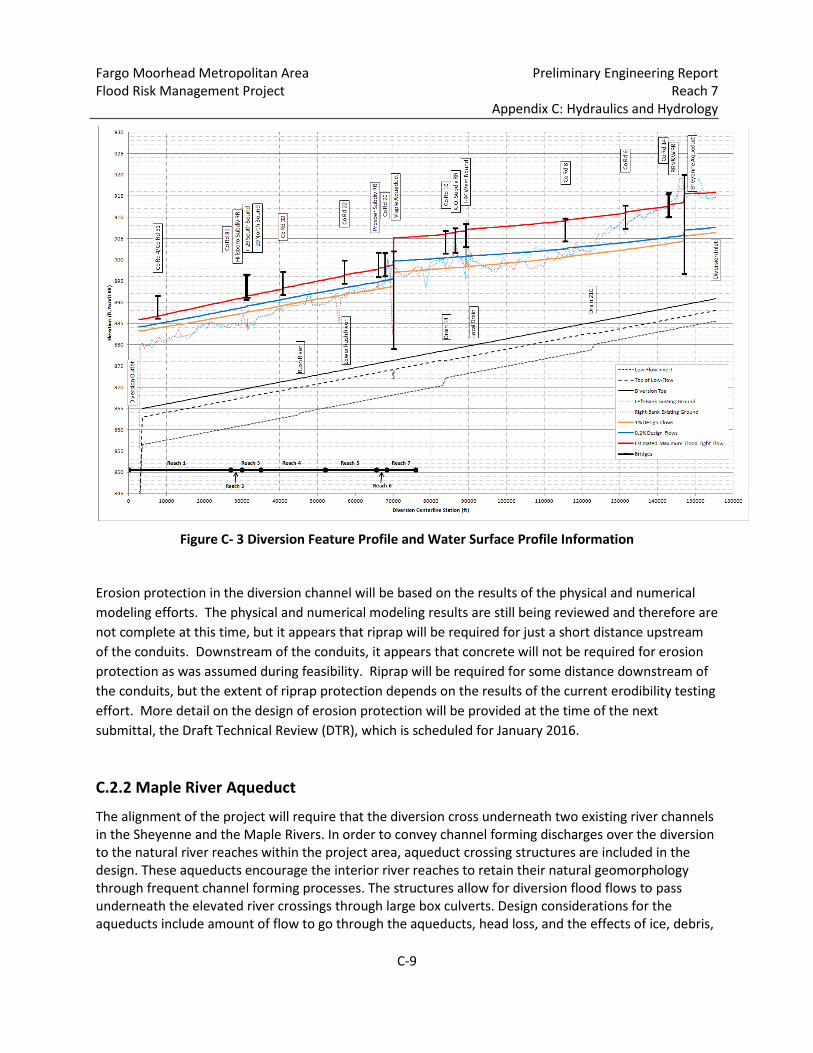
One additional concern for hydraulic roughness is the possibility of wetland vegetation and other vegetation specified in the planting plan, growing to a tall enough height to impact the channel roughness values. Through review of literature on the subject, there should be little to no impact from taller vegetation. Technical Report EL-97-9, “Hydraulic Impacts of Riparian Vegetation” (Fischenich 1997), indicates when the water depth is two to three times the height of the vegetation (even substantial woody vegetation), there is little to no required adjustment in the n-value. For major flood events, the depth of water in the channel will be well above three times the height of even unmaintained vegetation. Since the vegetation will be maintained regularly and the vegetation will tend to “lie down” during flood events, no adjustment to the n-value of 0.030 will be considered. Diversion feature profile and water surface profile information is provided in Figure C- 3.
Fargo Moorhead Metropolitan Area Preliminary Engineering Report Flood Risk Management Project Reach 7 Appendix C: Hydraulics and Hydrology
C-9
Figure C- 3 Diversion Feature Profile and Water Surface Profile Information
Erosion protection in the diversion channel will be based on the results of the physical and numerical modeling efforts. The physical and numerical modeling results are still being reviewed and therefore are not complete at this time, but it appears that riprap will be required for just a short distance upstream of the conduits. Downstream of the conduits, it appears that concrete will not be required for erosion protection as was assumed during feasibility. Riprap will be required for some distance downstream of the conduits, but the extent of riprap protection depends on the results of the current erodibility testing effort. More detail on the design of erosion protection will be provided at the time of the next submittal, the Draft Technical Review (DTR), which is scheduled for January 2016.
C.2.2 Maple River Aqueduct
The alignment of the project will require that the diversion cross underneath two existing river channels in the Sheyenne and the Maple Rivers. In order to convey channel forming discharges over the diversion to the natural river reaches within the project area, aqueduct crossing structures are included in the design. These aqueducts encourage the interior river reaches to retain their natural geomorphology through frequent channel forming processes. The structures allow for diversion flood flows to pass underneath the elevated river crossings through large box culverts. Design considerations for the aqueducts include amount of flow to go through the aqueducts, head loss, and the effects of ice, debris,
Fargo Moorhead Metropolitan Area Preliminary Engineering Report Flood Risk Management Project Reach 7 Appendix C: Hydraulics and Hydrology
C-10
and sediment. Head loss across the Maple River aqueduct will affect the hydraulic profiles upstream of the aqueduct; therefore the final height of the levee and bridges upstream of the Maple River aqueduct will not be set prior to having solid knowledge of the Maple River aqueduct design. The 300 ft long Maple River aqueduct serves as a bridge allowing Maple River flow to pass over the diversion channel. Up through bank full flow conditions all Maple River flow will continue on its path to towards the confluence with the Sheyenne River within the benefited area. The aqueduct structure is being designed to pass fish at least up through bank full conditions. Roughness elements will be added to the more restrictive 50 ft wide channel cross-section of the aqueduct in order to provide hydraulic conditions aqueduct for passing a wide range of species. A flume study investigating the detailed design of the roughness elements is scheduled for the summer and fall of 2015. The size and roughness of the Maple River aqueduct, in conjunction with the Maple River spillway which will divert a portion of higher Maple River flows into the diversion, will limit the amount of flow into the benefited area of the FMM project. Based on a study of flood damage potential along the Maple River and Sheyenne River within the benefited area, the target flow range through the aqueduct for the 1% event on the Maple River is 3000 cfs to 3500 cfs. Based on the physical and numerical modeling work, which is still being reviewed and therefore is not complete at this time, it appears that riprap will be required for just a short distance upstream of the aqueduct in the engineered channel. In the engineered channel downstream of the aqueduct it probably makes sense to construct a short rock ramp with boulders to assure low flow conditions that will pass fish and disperse the energy of higher flows exiting the aqueduct.
C.2.3 Maple River Flow Split The Maple River will be rerouted over the aqueduct where it crosses the diversion channel. The amount of Maple River flow going over the aqueduct down to its confluence with the Sheyenne River will be limited. This limitation is the result of the desire to keep the size of the aqueduct reasonable and restrict the amount of flow entering the risk reduction area. Excess Maple River flow will be transferred to the diversion channel through a spillway. The location where flow leaves the Maple River via this spillway is known as the flow split and is controlled by the upstream most weir of the spillway, or control weir. The position, width, and elevation of the control weir have been thoroughly studied through one and two dimensional numerical modeling and physical modeling studies. The design target limitation for flow entering the aqueduct and flowing into the risk reduction area for a 1% (100-yr) event flow was originally 3000 cfs, but has been revised to between 3000 and 3500 cfs. This final design flow will depend on the final design of the control weir and roughness downstream. Two primary positions of the control weir were studied. Some minor shifting of the preferred, or second primary position studied, was modeled to determine the optimum position. Areas of recirculation were observed upstream of the control weir. The extent of the recirculation depended on the control weir
Fargo Moorhead Metropolitan Area Preliminary Engineering Report Flood Risk Management Project Reach 7 Appendix C: Hydraulics and Hydrology
C-11
design and influenced the distribution of flow between the spillway and rerouted Maple River. The design of the control weir is detailed in Section 3.5 and 3.7 of the Draft Hydraulic Optimization Report. A discussion of how model tailwater assumptions and roughness influences the flow split is detailed in Sections 3.10 and 3.11 of the Draft Hydraulic Optimization Report. The most recent hydraulic studies produced higher flow rates passing through the aqueduct than expected. These flows were determined to be 4,120 cfs from physical model studies and 3,840 cfs from two dimensional numerical model studies, as described in Section 3.11.3 of the Draft Hydraulic Optimization Report. However, there is uncertainty regarding roughness in both models, and regarding eddy viscosity in the two dimensional model. The incorporation of roughness elements in the aqueduct design is expected to further reduce this flow. In fact, HEC-RAS model runs with roughness of 0.045 for the engineered channel and 0.040 for the aqueduct produced a flow of 3300 cfs. A physical model flume study of the aqueduct and roughness elements will further confirm headloss through the aqueduct, water surface elevations upstream of the aqueduct, and the flow produced by the flow split. The study is scheduled for the summer and fall of 2015.
C.2.4 Spillway The Maple River spillway serves as a path for Maple River flow to enter the diversion during greater than bank full flow conditions on the Maple River. The Maple River spillway works in conjunction with the Maple River aqueduct to limit the amount of flow into the benefited area of the FMM project. The spillway is a passive structure that contains three weirs that control the location of energy dissipation within the spillway. The spillway design will be a rock weir design consisting of an upstream control weir and two additional weirs. A chute type spillway was also considered. The chute type spillway would produce high erosive velocities along the whole length. The rock weir type spillway dissipates energy in a more controlled manner versus a chute type spillway and was therefore preferred. The selection of the type of spillway was studied in a separate Spillway Design Report. Additional hydraulic modeling was performed with the rock weir design integrated into the larger Reach 7 project area. The design details are documented in Sections 3.6, 3.7, and 3.8 of the Hydraulic Optimization Report. The initial spillway orientation was to have the spillway centerline approximately at a 45 degree angle from the Maple River centerline. An alternative spillway orientation was determined in later hydraulic modeling studies and had the spillway centerline at an approximate 90 degree angle to the Maple River centerline. These different spillway positions are related to the position of the control weir as discussed in the previous section and further detailed in Section 3.5 and 3.7 of the Draft Hydraulic Optimization Report. The second orientation studied was preferred as it produced a smaller footprint yielding some reduction in cost. The control weir width was also reduced slightly for the preferred orientation to 245 ft. This was due to observations made during hydraulic modeling that an edge jet effect was observed if the weir length and pool width differed much more than about 10%. This edge jet effect is essentially an area of high velocity flow along the edge of the spillway due to geometry changes between the weir cross section and pool cross section. The effect has been observed on other projects. Reduction in the edge jet effect can also be accomplished through vertical walls or abutments at the ends of each weir.

Fargo Moorhead Metropolitan Area Preliminary Engineering Report Flood Risk Management Project Reach 7 Appendix C: Hydraulics and Hydrology
C-12
These minor geometric changes were studied during the hydraulic modeling activities and may be incorporated into the final design pending further study. The upstream and downstream slopes were set at 1 vertical to 4 horizontal. As the design advances, the downstream slope may be made more gradual depending on velocities and erosion protection methods used. Erosion protection will be designed during the next phase. Each weir will be subjected to high supercritical velocities ending in a small hydraulic jump. It is important that the control weir be a permanent feature since it will control the flow. Concrete will likely be the material type for this feature, with an additional rock or concrete apron extending downstream of the hydraulic jump. The other weirs will likely be constructed from riprap with a rock apron extending past the hydraulic jump. The extent and type of erosion protection, the upstream and downstream slopes leading to and away from the weir, and whether the downstream two weirs require sheet pile will be determined by the time of the draft technical review (DTR) scheduled for January 2016. The upstream-most weir adjacent to the upstream end of the engineered channel will have a surface that can be used as a maintenance access road and will have sheet pile as a hydraulic fail-safe feature (sheet pile may also be required for geotechnical or structural reasons). A rough surface is acceptable for the two weirs further downstream in the spillway since vehicle access is not a requirement at these two weirs.
C.2.5 Engineered Channel The Maple River will be rerouted from its natural channel through the aqueduct. The rerouted channel will then connect back with the natural Maple River. This rerouted channel on either side of the aqueduct has been referred to the engineered channel during hydraulic modeling studies. The cross section for the engineered channel has been determined primarily using geotechnical considerations and is modeled after the natural Maple River channel. The length of the rerouted channel is 4400 ft long compared to the original channel length of 5500 ft. The slope of the rerouted channel is 0.000068 compared to the original channel slope of 0.000055. The potential roughness variability of the engineered channel and transition issues between the natural and engineered channels are detailed in Sections 3.12 and 3.13 of the Hydraulic Optimization Report. Erosion protection will be necessary at and upstream of the flow split and at the ends of the aqueduct. This protection will likely be rock. Soil erodibility testing is currently being performed at the project site. The results of the testing will be used to determine the need for rock protection between these areas. Both velocity and shear stress are available from hydraulic modeling results and can be taken as the applied forcing. Resistive forcing will be obtained from the erodibility testing. Erosion protection may change the roughness of the engineered channel and flow distribution between the spillway and rerouted Maple River channel. Vegetation planting along the channel may be used to enhance roughness.

Fargo Moorhead Metropolitan Area Preliminary Engineering Report Flood Risk Management Project Reach 7 Appendix C: Hydraulics and Hydrology
C-13
C.2.6 Left Bank EMB Gap The capacity of the conduits beneath the Maple River aqueduct is limited. For extreme flood events (events exceeding a 0.2% chance of occurrence) diversion flow will be allowed to exit the diversion via a gap in the left bank EMB in order to prevent raising or overtopping of the southern wall of the aqueduct.
C.2.7 Maple River Ice Retention Structure An ice retention structure (IRS) is proposed at the first bend upstream of the aqueduct/spillway structure in reach 7. This purpose of the structure will be to stabilize the ice cover and reduce the ice volume supply for a potential ice jam downstream and for erosion due to large competent ice floes and accompanying higher bed shear in the aqueduct/spillway and engineered reach. The IRS will achieve this purpose by retaining ice upstream of the aqueduct/spillway structure for slightly longer than the natural system in an effort to allow the ice time to thermally decay and rot so that it is too weak when it approaches the structure to jam or cause erosion. This will be accomplished by meeting several key design goals to • encourage bridging of ice at freeze-up • raise water surface at freeze-up to create pool as deposition area for frazil ice and maximum thermal ice cover • create a stronger ice cover at this point which will hold slightly longer than natural conditions • take advantage of sharp bend where ice is probably well keyed in under natural conditions

Fargo Moorhead Metropolitan Area Preliminary Engineering Report Flood Risk Management Project Reach 7 Appendix C: Hydraulics and Hydrology
C-14
C.2.8 Controlling Elevations and Dimensions
The following table lists the finish elevations of key features of the project. All elevations shown refer to NAVD88.
Table C-3: Controlling Elevations
DESCRIPTION ELEVATION (NAVD88)
Low Flow Channel Invert at Downstream End of Reach 7 – Sta 683+00 867.89
Low Flow Channel at Centerline of Aqueduct – Sta 709+69 868.34
Low Flow Channel Invert at Upstream End of Reach 7 – Sta 755+00 869.11
Bottom of Conduits (excluding low flow channel) 869.33
Top of Conduits 879.00
Aqueduct Channel Invert (Winter Channel Invert) 881.00
Upstream-most Spillway Weir Crest 894.00
Top of Aqueduct Walls 904.00
Left Bank EMB Gap 900.00
The following table lists the required dimensions of key features of the project.
Table C-4: Required Dimensions
DESCRIPTION DIMENSION (FEET)
Conduit Opening Height (879.00 – 869.33; see Table 3) 9.67
Minimum Total Width of Conduit Openings (total width – pier width) 273
Spillway Weir Crest Length (perpendicular to general flow direction) 245
Spillway Bottom Width 220
Aqueduct Opening Width (perpendicular to Maple River centerline) 50
Left Bank EMB Gap Length (in direction of diversion centerline) 1000

Fargo Moorhead Metropolitan Area Preliminary Engineering Report Flood Risk Management Project Reach 7 Appendix C: Hydraulics and Hydrology
C-15
C.3 FURTHER DESIGN GUIDELINES Further guidance for the design of this reach and other reaches can be found in Appendix M: Memos for Record and Guidance Memos.