appendix a -...
TRANSCRIPT

Appendix AFourier Series
A.1 General Equations
A periodic function (Wylie 1972) can be represented by a series that is expressed as
f x = 0 5Ao +A1 cosx+A2 cos2x + +Am cosmx+B1 sinx
+B2 sin2x+ +Bm sinmx
or
f x = 0 5Ao +∞
m= 1
Am cosmx+∞
m= 1
Bm sinmx (A.1)
The series given in Eq. (A.1) is known as a Fourier series and is used to express periodicfunctions such as those shown in Figure A.1. The coefficients A and B in Eq. (A.1) are evalu-ated over a 2π period starting at a given point d. The value of Ao can be obtained by integratingEq. (A.1) from x = d to x = d + 2π.Thus,
d + 2π
df x dx= 0 5Ao
d + 2π
ddx+A1
d + 2π
dcosx dx+
+Am
d + 2π
dcosmx dx+B1
d + 2π
dsinx dx+
+Bm
d + 2π
dsinmx dx
Stress in ASME Pressure Vessels, Boilers, and Nuclear Components, First Edition. Maan H. Jawad.© 2018, The American Society of Mechanical Engineers (ASME), 2 Park Avenue,New York, NY, 10016, USA (www.asme.org). Published 2018 by John Wiley & Sons, Inc.
0003135125.3D 309 24/8/2017 8:27:00 PM
Downloaded From: http://ebooks.asmedigitalcollection.asme.org/ on 07/22/2018 Terms of Use: http://www.asme.org/about-asme/terms-of-use

The first term in the right-hand side of the equation gives πAo. All other terms on the right-handside are zero because of the relationships
d + 2π
dcosmx dx= 0 m 0
d + 2π
dsinmx dx= 0
Hence,
Ao =1π
d + 2π
df x dx (A.2)
The Am term in Eq. (A.1) can be obtained by multiplying both sides of the equation by cos mx.
d + 2π
df x cosmx dx=
12Ao
d + 2π
dcosmx dx+A1
d + 2π
dcosx cosmx dx+
+Am
d + 2π
dcosmx cosmx dx+B1
d + 2π
dsinx cosmx dx+
+Bm
d + 2π
dsinmx cosmx dx
(A.3)
Since
d + 2π
dcosmxcosnx dx= 0 m n
d + 2π
dcos2mx dx= π m 0
d + 2π
dcosmxsinnx dx= 0
x
x
Figure A.1 Periodic functions
310 Appendix A
0003135125.3D 310 24/8/2017 8:27:01 PM
Downloaded From: http://ebooks.asmedigitalcollection.asme.org/ on 07/22/2018 Terms of Use: http://www.asme.org/about-asme/terms-of-use

Equation (A.3) becomes
d + 2π
df x cosmx dx=Amπ
or
Am =1π
d + 2π
df x cosmx dx (A.4)
Similarly the values of Bm can be found by multiplying both sides of Eq. (A.1) by sin mx.Using the expressions
d + 2π
dsinmxsinnx dx= 0 m n
and
d + 2π
dsin2mx dx= π
the equation becomes
Bm =1π
d + 2π
df x sin mx dx (A.5)
Accordingly, we can state that for a given periodic function f(x), a Fourier expansion can bewritten as shown in Eq. (A.1) with the various constants obtained from Eqs. (A.2), (A.4),and (A.5).
Example A.1Express the function shown in Figure A.2 in a Fourier series.
Solution
f x = 0 −π < x < 0
f x = po 0 < x < π
d = −π
From Eq. (A.2),
Ao =1π
0
−π0 dx+
1π
π
0podx
311Appendix A
0003135125.3D 311 24/8/2017 8:27:01 PM
Downloaded From: http://ebooks.asmedigitalcollection.asme.org/ on 07/22/2018 Terms of Use: http://www.asme.org/about-asme/terms-of-use

or
Ao = po
From Eq. (A.4),
Am =1π
π
0po cosmx dx
Am = 0
From Eq. (A.5),
Bm =1π
π
0po sinmx dx
=pomπ
−cosmx π0
=−pomπ
cosmπ−1
Bm =2pomπ
when m is odd
= 0 when m is even
–2π –π π 2π 3πx
x
x
x
1.0 m= 1
m= 1,3
m= 1,3,5
po
popo
0.5
1.0
0.5
1.0
0.5
–π π2
π
–π π2– π
2π
–π π2– π
2π
π2–
Figure A.2 Periodic rectangular function
312 Appendix A
0003135125.3D 312 24/8/2017 8:27:01 PM
Downloaded From: http://ebooks.asmedigitalcollection.asme.org/ on 07/22/2018 Terms of Use: http://www.asme.org/about-asme/terms-of-use

Therefore, the expansion of the function shown in Figure A.2 is expressed as
f x = 0 5po +2poπ
∞
m = 1 3,…
1msinmx
A plot of this equation with m = 1, 3, 5 is shown in Figure A.2.
A.2 Interval Change
In applying the Fourier series to plate and shell problems, it is more convenient to specifyintervals other than 2π. Defining the new interval as 2p, Eqs. (A.2), (A.4), and (A.5) can bewritten as
Ao =1p
d + 2p
df x dx (A.6)
Am =1p
d + 2p
df x cos
mπx
pdx (A.7)
Bm =1p
d + 2p
df x sin
mπx
pdx (A.8)
where 2p = period of function, and the series can be written as
f x =12Ao +
∞
m = 1
Am cosmπx
p+
∞
m = 1
Bm sinmπx
p(A.9)
Example A.2Find the Fourier expansion of the function f(x) = cos x as shown in Figure A.3.
SolutionThe period 2p is equal to π. Thus, p = π/2 and d = −π/2.
–π π2–
xπ2
π
Figure A.3 Periodic cosine function
313Appendix A
0003135125.3D 313 24/8/2017 8:27:01 PM
Downloaded From: http://ebooks.asmedigitalcollection.asme.org/ on 07/22/2018 Terms of Use: http://www.asme.org/about-asme/terms-of-use

Ao =1
π 2
π 2
−π 2cosx dx=
4π
Am =2π
π 2
−π 2cosx cos
mπx
π 2dx=
4π
∞
m = 1
−1 m + 1
4m2−1
Bm = 0
and from Eq. (A.9),
f x =2π+4π
∞
m = 1
−1 m+ 1
4m2−1cos2mx
A.3 Half-Range Expansions
If a function is symmetric with respect to the axis of reference as shown in Figure A.4, then thecoefficient integral can be simplified by integrating over one-half the period. This integrationcan be performed as an even or odd function.Hence, for an even periodic function,
Ao =2p
p
0f x dx
Am =2p
p
0f x cos
mπx
pdx
Bm = 0
(A.10)
(a) (b)
Odd
x
x
x
Odd
Even
(c)
Figure A.4 Periodic symmetric function. (a) Odd step function, (b) odd continuous function, and(c) even step function
314 Appendix A
0003135125.3D 314 24/8/2017 8:27:01 PM
Downloaded From: http://ebooks.asmedigitalcollection.asme.org/ on 07/22/2018 Terms of Use: http://www.asme.org/about-asme/terms-of-use

For an odd periodic function,
Ao =Am = 0
Bm =2p
p
0f x sin
mπx
pdx
(A.11)
It should be noted that the even and odd functions defined by Eqs. (A.10) and (A.11) andFigure A.4 do not refer necessarily to the shape of the function but rather to the reference linefrom which they are defined. This can best be illustrated by Example A.3.
Example A.3Figure A.5 shows a plot of the function y = x − x2. Obtain and plot the Fourier series expansionof this function (a) from y = −1 to y = 1; (b) as an even series from y = 0 to y = 1; and (c) as anodd series from y = 0 to y = 1.
2.0
1.0 1.0
y
2.0
–1.0 1.0Continuous function
Even function
2.0
–1.0 1.0 2.0
2.01.0Odd function
–1.0
2.0x
Figure A.5 Function y = x − x2
315Appendix A
0003135125.3D 315 24/8/2017 8:27:01 PM
Downloaded From: http://ebooks.asmedigitalcollection.asme.org/ on 07/22/2018 Terms of Use: http://www.asme.org/about-asme/terms-of-use

Solutiona. d = −1, 2p = 2 or p = 1
Ao =1
−1x−x2 dx= −
23
Am =1
−1x−x2 cos
mπx
1dx= −
4cosmπm2π2
Bm =1
−1x−x2 sin
mπx
1dx= −
2cosmπmπ
f x = −13−
∞
m= 1
4cosmπm2π2
cosmπx−∞
m = 1
2cosmπmπ
sinmπx
= −13−4π2
∞
m= 1
−1 m
m2cosmπx−
2π
∞
m= 1
−1 m
msinmπx
b.Ao = 2
1
0x−x2 dx=
13
Am = 21
0x−x2 cos
mπx
1dx= −
2 1 + cosmπm2π2
Bm = 0
f x =16−
∞
m= 1
2 1 + cosmπm2π2
cosmπx
c. Ao =Am = 0
Bm = 21
0x−x2 sin
mπx
1dx=
4 1−cosmπm3π3
f x =∞
m= 1
4 1−cosmπm3π3
sinmπx
A.4 Double Fourier Series
In solving rectangular plate problems of length a and width b, it is customary to express theapplied loads in terms of a single or double series. The double Fourier series is normallyexpressed as an odd periodic function with a half-range period given between 0 and a forone side of the plate and 0 and b for the other side. Thus,
316 Appendix A
0003135125.3D 316 24/8/2017 8:27:02 PM
Downloaded From: http://ebooks.asmedigitalcollection.asme.org/ on 07/22/2018 Terms of Use: http://www.asme.org/about-asme/terms-of-use

f x,y =∞
m= 1
∞
n= 1
Bmnsinmπx
asin
nπy
b(A.12)
where
Bmn =4ab
b
0
a
0f x,y sin
mπx
asin
nπy
bdxdy (A.13)
Example A.4The rectangular plate shown in Figure A.6 is subjected to a uniform pressure po. Determine theFourier expansion for the pressure.
SolutionFrom Eq. (A.13),
Bmn =4poab
b
0
a
0sin
mπx
asin
nπy
bdxdy
=16poπ2mn
m,n are odd functions
f x,y =16poπ2
∞
m= 1 3,…
∞
n = 1 3,…
1mn
sinmπx
asin
nπy
b
y
b
xa
Figure A.6 Rectangular plate
317Appendix A
0003135125.3D 317 24/8/2017 8:27:02 PM
Downloaded From: http://ebooks.asmedigitalcollection.asme.org/ on 07/22/2018 Terms of Use: http://www.asme.org/about-asme/terms-of-use

0003135125.3D 318 24/8/2017 8:27:02 PM
Downloaded From: http://ebooks.asmedigitalcollection.asme.org/ on 07/22/2018 Terms of Use: http://www.asme.org/about-asme/terms-of-use

Appendix BBessel Functions
B.1 General Equations
In many plate and shell applications involving circular symmetry, the resulting differentialequations are solved by means of a power series known as Bessel functions. Some of thesefunctions are discussed in this appendix.The differential equation
d2y
dx2+1x
dy
dx+ y = 0 (B.1)
is referred to as Bessel’s equation of zero order. Its solution (Bowman 1977) is given by thefollowing power series:
y=C1Jo x +C2Yo x (B.2)
where C1 and C2 = constants obtained from boundary conditions and Jo(x) = Bessel function ofthe first kind of zero order.
Jo x = 1−x2
22+
x4
22 42−
x6
22 42 62+
=∞
m= 0
−1 m
m 2
x
2
2m
Yo(x) = Bessel function of the second kind of zero order.
Stress in ASME Pressure Vessels, Boilers, and Nuclear Components, First Edition. Maan H. Jawad.© 2018, The American Society of Mechanical Engineers (ASME), 2 Park Avenue,New York, NY, 10016, USA (www.asme.org). Published 2018 by John Wiley & Sons, Inc.
0003135126.3D 319 24/8/2017 8:18:42 PM
Downloaded From: http://ebooks.asmedigitalcollection.asme.org/ on 07/22/2018 Terms of Use: http://www.asme.org/about-asme/terms-of-use

Yo x = Jo xdx
x J2o x
= Jo x lnx+x2
22−
x4
22 421 +
12
+x6
22 42 621 +
12+13
−
Equation (B.1) is usually encountered in a more general form as
x2d2y
dx2+ x
dy
dx+ x2−k2 y = 0 (B.3)
The solution of this equation (Hildebrand 1964) is
y=C1Jk x +C2J−k x
when k is not zero or a positive integer or
y=C1Jk x +C2Yk x
when k is zero or a positive integer and where
Jk x =Bessel function of the first kind of order k
=∞
m = 0
−1 m
m m+ kx
2
2m+ k
J−k x =Bessel function of the first kind of order k
=∞
m = 0
−1 m
m m−k
x
2
2m−k
Yk x =Bessel function of the second kind of order k
=2π
lnx
2+ γ Jk x −
12
k−1
m = 0
k−m−1m
x
2
2m−k
+12
∞
m= 0
−1 m+ 1 h m + h m + kx 2 2m+ k
m m + k
h m =m
r = 1
1r
m > 1
γ = 0 5772
A plot of Jo(x), J1(x), Yo(x), and Y1(x) is shown in Figure B.1. Also, Table B.1 gives some valuesof J(x) and Y(x).
320 Appendix B
0003135126.3D 320 24/8/2017 8:18:43 PM
Downloaded From: http://ebooks.asmedigitalcollection.asme.org/ on 07/22/2018 Terms of Use: http://www.asme.org/about-asme/terms-of-use

–1.0
1.0
1.0
–1.0
2 4 6 8 10
Yo(x)Y1(x)
xY(x)
2 4
(a)
(b)
J1(x)
Jo(x)
6 8 10xJ(x)
Figure B.1 A plot of various Bessel functions: (a) Jo and J1 functions and (b) Yo and Y1 functions
Table B.1 Values of Jo, J1, Yo, and Y1
(x) Jo(x) J1(x) Yo(x) Y1(x)
0.0 1.0000 0.0000 −∞ −∞0.5 0.9385 0.2423 −0.4445 −1.47151.0 0.7652 0.4401 0.0883 −0.78121.5 0.5118 0.5579 0.3825 −0.41232.0 0.2239 0.5767 0.5104 −0.10702.5 −0.0484 0.4971 0.4981 0.14593.0 −0.2601 0.3391 0.3769 0.32473.5 −0.3801 0.1374 0.1890 0.41024.0 −0.3972 −0.0660 −0.0169 0.39794.5 −0.3205 −0.2311 −0.1947 0.30105.0 −0.1776 −0.3276 −0.3085 0.14795.5 −0.0068 −0.3414 −0.3395 −0.02386.0 0.1507 −0.2767 −0.2882 −0.17506.5 0.2601 −0.1538 −0.1732 −0.27417.0 0.3001 −0.0047 −0.0260 −0.30277.5 0.2663 0.1353 0.1173 −0.25918.0 0.1717 0.2346 0.2235 −0.15818.5 0.0419 0.2731 0.2702 −0.02629.0 −0.0903 0.2453 0.2499 0.10439.5 −0.1939 0.1613 0.1712 0.203210.0 −0.2459 0.0435 0.0557 0.2490
0003135126.3D 321 24/8/2017 8:18:43 PM
Downloaded From: http://ebooks.asmedigitalcollection.asme.org/ on 07/22/2018 Terms of Use: http://www.asme.org/about-asme/terms-of-use
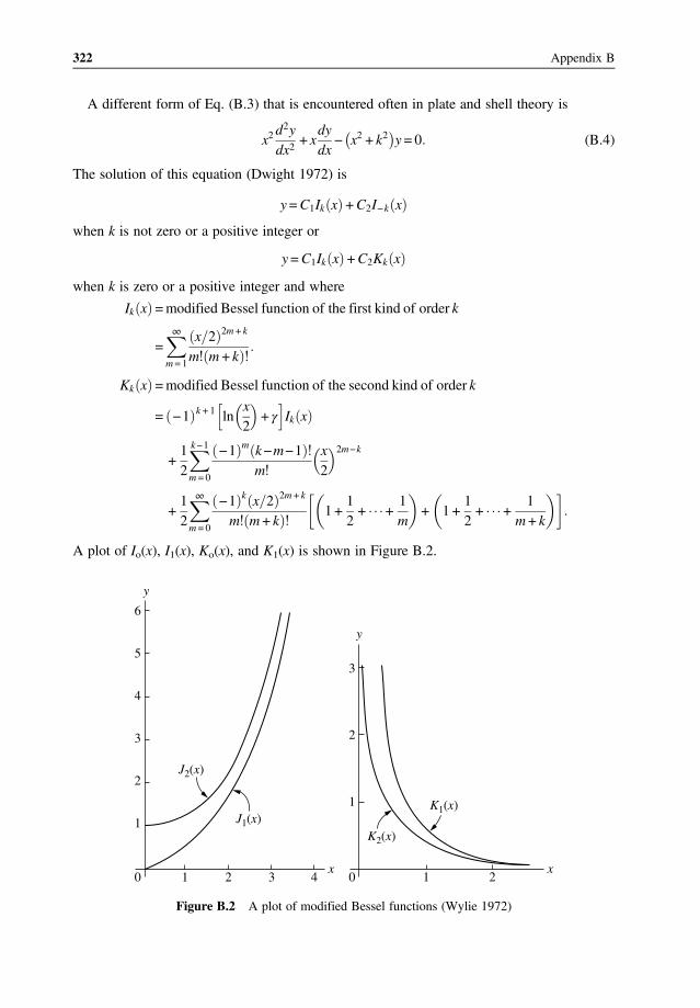
A different form of Eq. (B.3) that is encountered often in plate and shell theory is
x2d2y
dx2+ x
dy
dx− x2 + k2 y = 0 (B.4)
The solution of this equation (Dwight 1972) is
y=C1Ik x +C2I−k x
when k is not zero or a positive integer or
y=C1Ik x +C2Kk x
when k is zero or a positive integer and where
Ik x =modified Bessel function of the first kind of order k
=∞
m= 1
x 2 2m + k
m m + k
Kk x =modified Bessel function of the second kind of order k
= −1 k + 1 lnx
2+ γ Ik x
+12
k−1
m = 0
−1 m k−m−1m
x
2
2m−k
+12
∞
m = 0
−1 k x 2 2m + k
m m+ k1 +
12+ +
1m
+ 1 +12+ +
1m+ k
A plot of Io(x), I1(x), Ko(x), and K1(x) is shown in Figure B.2.
6
y
y
x x
5
4
3
2
2
3
1
1
0
J2(x)
J1(x)K1(x)
K2(x)
1 2 0 1 23 4
Figure B.2 A plot of modified Bessel functions (Wylie 1972)
322 Appendix B
0003135126.3D 322 24/8/2017 8:18:43 PM
Downloaded From: http://ebooks.asmedigitalcollection.asme.org/ on 07/22/2018 Terms of Use: http://www.asme.org/about-asme/terms-of-use

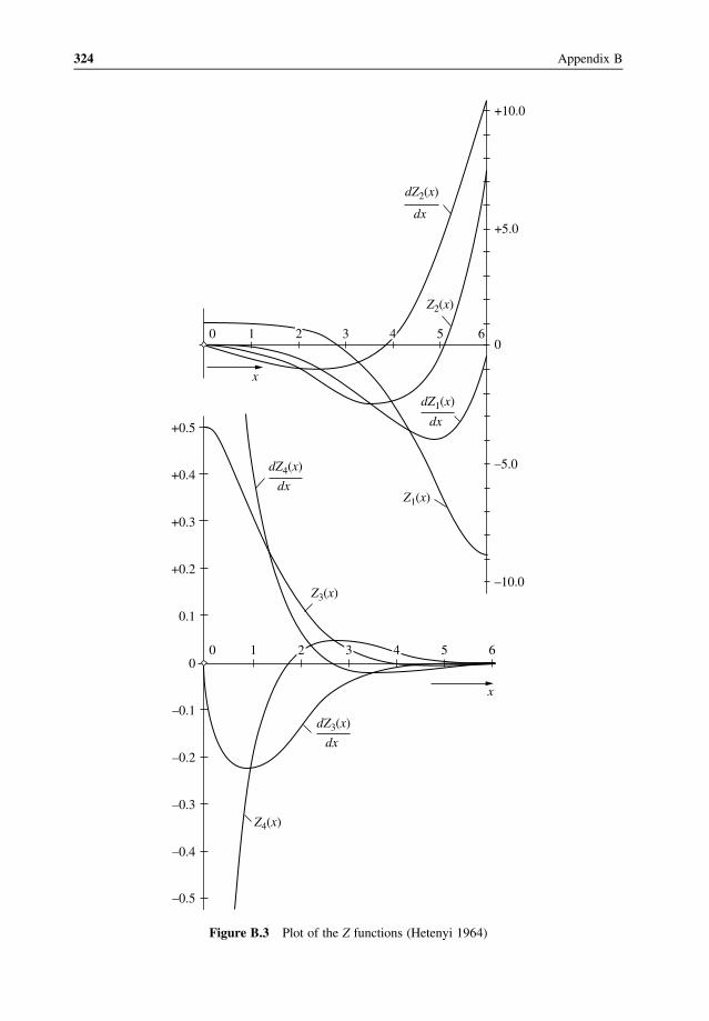
Another equation that is often encountered in plate and shell theory is given by
x2d2y
dx2+ x
dy
dx− ix2 + k2 y = 0 (B.5)
The solution of this equation (Hetenyi 1964) for the important case of k = 0 is given by
y=C1Z1 x +C2Z2 x +C3Z3 x +C4Z4 x (B.6)
where
Z1 x = ber x =∞
m= 0
−1 m x 2 4m
2m 2
Z2 x = −bei x = −∞
m = 0
−1 m x 2 4m + 2
2m+ 1 2
Z3 x = −2πkei x =
Z1 x
2−2π
R1 + lnγx
2Z2 x
Z4 x = −2πker x =
Z2 x
2−2π
R2 + lnγx
2Z1 x
R1 =x
2
2−h 3
3 2
x
2
6+h 5
5 2
x
2
10−
R2 =h 2
2 2
x
2
4−h 4
4 2
x
2
8+h 6
6 2
x
2
12−
h n = 1 +12+13+ +
1n
γ = 0 5772
A plot of Z1(x), Z2(x), Z3(x), Z4(x), and their derivatives is shown in Figure B.3.
B.2 Some Bessel Identities
The derivatives and integrals of Bessel functions follow a certain pattern. The identities givenhere are needed to solve some of the problems given in this text.
d
dxxJ1 x = xJo x
d
dxJo x = −J1 x
d
dxxnJn x = xnJn−1 x
d
dx
Jn x
xn=−Jn+ 1 x
xn
323Appendix B
0003135126.3D 323 24/8/2017 8:18:43 PM
Downloaded From: http://ebooks.asmedigitalcollection.asme.org/ on 07/22/2018 Terms of Use: http://www.asme.org/about-asme/terms-of-use
–10.0
–5.0
0
Z2(x)
+5.0
+10.0
65310
x
x
dx
dZ2(x)
dx
dZ1(x)
dx
dZ4(x)
dx
dZ3(x)
Z1(x)
Z3(x)
Z4(x)
2 4
65310
0.1
0
–0.1
–0.2
–0.3
–0.4
–0.5
+0.2
+0.3
+0.4
+0.5
2 4
Figure B.3 Plot of the Z functions (Hetenyi 1964)
324 Appendix B
0003135126.3D 324 24/8/2017 8:18:43 PM
Downloaded From: http://ebooks.asmedigitalcollection.asme.org/ on 07/22/2018 Terms of Use: http://www.asme.org/about-asme/terms-of-use

d2Z1 x
dx2= Z2 x −
1x
dZ1 x
dx
d2Z2 x
dx2= −Z1 x −
1x
dZ2 x
dx
d2Z3 x
dx2= Z4 x −
1x
dZ3 x
dx
d2Z4 x
dx2= −Z3 x −
1x
dZ4 x
dx
The last four equations are needed in the solution of circular plates on elastic foundation. Inthese equations the value of (kx) is needed rather than (x) in the Z functions. In this case, theseequations take on the form
k2Z1 kx = k2Z2 x −k
xZ1 kx
k2Z2 kx = −k2Z1 x −k
xZ2 kx
k2Z3 kx = k2Z4 x −k
xZ3 kx
k2Z4 kx = −k2Z3 x −k
xZ4 kx
B.3 Simplified Bessel Functions
As x approaches zero, the various Bessel functions can be expressed as
Jk x =xk
2k k
Yk x =−2k k−1
πx−k k 0
Yo x =2πlnx
Ik x =xk
2kk
Kk x = 2k−1 k−1 x−k k 0
Ko x = − lnx
Z1 x = 1 0 Z2 x = −x2
4
Z3 x =12
Z4 x =2πlnγx
2
325Appendix B
0003135126.3D 325 24/8/2017 8:18:44 PM
Downloaded From: http://ebooks.asmedigitalcollection.asme.org/ on 07/22/2018 Terms of Use: http://www.asme.org/about-asme/terms-of-use

dZ1 x
dx= −
x3
16dZ3 x
dx=x
πlnγx
2
dZ2 x
dx= −
x
2dZ4 x
dx=
2πx
As x approaches infinity, the various Bessel functions can be expressed as
Jk x =2πxcos x−ξk ξk = 2k + 1
π
4
Yk x =2πxsin x−ξk
Ik x =ex
2πx
Kk x =e−x
2x π
Z1 x = ηcosσ Z2 x = −ηsinσ
Z3 x = β sinτ Z4 x = −βcosτ
η=1
2πxex 2 β =
2πxe−x 2
σ =x
2−π
8τ =
x
2+π
8
dZ1 x
dx=
η
2cosσ−sinσ
dZ2 x
dx=−η
2cosσ + sinσ
dZ3 x
dx=
β
2cosτ−sinτ
dZ4 x
dx=−β
2cosτ + sinτ
326 Appendix B
0003135126.3D 326 24/8/2017 8:18:44 PM
Downloaded From: http://ebooks.asmedigitalcollection.asme.org/ on 07/22/2018 Terms of Use: http://www.asme.org/about-asme/terms-of-use

Appendix CConversion Factors
Pressure units
1 psi 1 N/mm2 1 bar 1 kPa 1 kgf/cm2
psi 1.0000 145.0 14.50 0.1450 14.22N/mm2 0.006895 1.000 0.1000 0.0010 0.09807bars 0.06895 10.000 1.000 0.0100 0.9807kPa 6.895 1000.0 100.00 1.000 98.07kgf/cm2 0.0703 10.20 1.020 0.0102 1.000
1 N/mm2 = 1 MPa.
Stress units
1 ksi 1 kN/mm2 1MPa 1 kgf/mm2
ksi 1.000 145.0 0.1450 1.422kN/mm2 0.006895 1.000 0.001 0.009807MPa 6.895 1000.00 1.000 9.807kgf/mm2 0.7033 102.0 0.1020 1.000
Force units
1 lb 1 kgf 1 N
lb 1.000 2.205 0.2248kgf 0.454 1.000 0.1020N 4.448 9.807 1.0000
Stress in ASME Pressure Vessels, Boilers, and Nuclear Components, First Edition. Maan H. Jawad.© 2018, The American Society of Mechanical Engineers (ASME), 2 Park Avenue,New York, NY, 10016, USA (www.asme.org). Published 2018 by John Wiley & Sons, Inc.
0003135127.3D 327 24/8/2017 4:26:26 PM
Downloaded From: http://ebooks.asmedigitalcollection.asme.org/ on 07/22/2018 Terms of Use: http://www.asme.org/about-asme/terms-of-use

0003135127.3D 328 24/8/2017 4:26:26 PM
Downloaded From: http://ebooks.asmedigitalcollection.asme.org/ on 07/22/2018 Terms of Use: http://www.asme.org/about-asme/terms-of-use

References
American Association of State Highway and Transportation Officials. 1996. Standard Specifications for HighwayBridges HB-16. Washington, DC: AASHTO.
American Concrete Institute, 1981. Concrete Shell Buckling, Publication SP-67. P. Seide, Stability of cylindricalreinforced concrete shells, SP 67–2. Detroit, Michigan.
American Institute of Steel Construction. 2013. Manual of Steel Construction-Allowable Stress Design. Chicago,IL: AISC.
American Iron and Steel Institute. 1981. Steel Penstocks and Tunnel Liners. Washington, DC: AISI.American Petroleum Institute. 2014. Design and Construction of Large, Welded, Low-Pressure Storage Tanks—API
620. Washington, DC: API.American Society of Mechanical Engineers. 2017a. Pressure Vessel Code, Section VIII, Division 1. New York,
NY: ASME.American Society of Mechanical Engineers. 2017b. Pressure Vessel-Alternate Rules, Section VIII, Division 2. New
York, NY: ASME.Baker, E. H., Cappelli, A. P., Kovalevsky, L., Rish, F. L., and Verette, R. M. 1968. Shell Analysis Manual—NASA
912. Washington, DC: National Aeronautics and Space Administration.Becker, H. July 1957. Handbook of Structural Stability—Part II—Buckling of Composite Elements NACA PB 128
305. Washington, DC: National Advisory Committee for Aeronautics.Bloom, F. and Coffin, D. 2001. Handbook of Thin Plate Buckling and Postbuckling. Boca Raton, FL: Chapman and
Hall/CRC.Boley, A. B. and Weiner, J. H. 1997. Theory of Thermal Stresses. New York, NY: Dover Publications.Bowman, F. 1977. Introduction to Bessel Functions. New York, NY: Dover Publications.Buchert, K. P. 1964. Stiffened Thin Shell Domes. AISC Engineering Journal, Vol. 1, pp. 78–82.Buchert, K. P. 1966. Buckling Considerations in the Design and Construction of Doubly Curved Space Structures.
International Conference on Space Structures, 1966—F8. England: University of Surry.Burgreen, D. 1971. Elements of Thermal Stress Analysis. Jamaica, NY: C.P. Press.Dwight, H. B. 1972. Tables of Integrals and Other Mathematical Data. New York, NY: Macmillan.Farr, J.R. and Jawad, M.H. 2010. Guidebook for the Design of ASME Section VIII Pressure Vessels. New York, NY:
ASME Press.Faupel, J. H. and Fisher, F. E. 1981. Engineering Design. New York, NY: Wiley-Interscience.Flugge, W. 1967. Stresses in Shells. New York, NY: Springer-Verlag.
Stress in ASME Pressure Vessels, Boilers, and Nuclear Components, First Edition. Maan H. Jawad.© 2018, The American Society of Mechanical Engineers (ASME), 2 Park Avenue,New York, NY, 10016, USA (www.asme.org). Published 2018 by John Wiley & Sons, Inc.
0003135128.3D 329 24/8/2017 4:28:05 PM
Downloaded From: http://ebooks.asmedigitalcollection.asme.org/ on 07/22/2018 Terms of Use: http://www.asme.org/about-asme/terms-of-use

Gallagher, R. H. 1975. Finite Element Analysis. Englewood Cliffs, NJ: Prentice Hall.Gerard, G. August 1957a. Handbook of Structural Stability—Part IV—Failure of Plates and Composite Elements.
NACA N62-55784. Washington, DC: National Advisory Committee for Aeronautics.Gerard, G. August 1957b. Handbook of Structural Stability—Part V—Compressive Strength of Flat Stiffened Panels.
NACA PB 185 629. Washington, DC: National Advisory Committee for Aeronautics.Gerard, G. 1962. Introduction to Structural Stability Theory. New York, NY: McGraw Hill.Gerard, G. and Becker, H. July 1957a. Handbook of Structural Stability—Part I—Buckling of Flat Elements. NACA
PB 185 628. Washington, DC: National Advisory Committee for Aeronautics.Gerard, G. and Becker, H. 1957b. Handbook of Structural Stability—Part III—Buckling of Curved Plates and Shells.
NACA TN 3783. Washington, DC: National Advisory Committee for Aeronautics.Gibson, J. E. 1965. Linear Elastic Theory of Thin Shells. New York, NY: Pergamon Press.Grandin, H. Jr. 1986. Fundamentals of the Finite Element Method. New York, NY: Macmillan.Harrenstien, H. P. and Alsmeyer, W. C. 1959. Structural Behavior of a Plate Resembling a Constant Thickness Bridge
Abutment Wingwall. Engineering Experiment Station Bulletin 182. Ames, IA: Iowa State University.Hetenyi, M. 1964. Beams on Elastic Foundation. Ann Arbor, MI: University of Michigan Press.Hildebrand, F. 1964. Advanced Calculus for Applications. Englewood Cliffs, NJ: Prentice Hall.Hult, J. H. 1966. Creep in Engineering Structures. London: Blaisdell Publishing Company.Iyengar, N. G. R. 1988. Structural Stability of Columns and Plates. New York, NY: John Wiley & Sons, Inc.Jawad, M. H. 1980. Design of Conical Shells Under External Pressure. Journal of Pressure Vessel Technology, Vol.
102, pp. 230–238.Jawad, M. H. 2004. Design of Plate and Shell Structures. New York, NY: ASME Press.Jawad,M. H. and Farr, J. R. 1989. Structural Analysis andDesign of Process Equipment. NewYork, NY: JohnWiley&
Sons, Inc.Jawad,M. H. and Jetter, R. I. 2011. Design andAnalysis of ASMEBoiler and Pressure Vessel Components in the Creep
Range. New York, NY: ASME Press.Jones, R. M. 2009. Deformation Theory of Plasticity. Blacksburg, VA: Bull Ridge Publishing.Koiter, W. T. 1943. The Effective Width of Flat Plates for Various Longitudinal Edge Conditions at Loads Far Beyond
the Buckling Load. Report No. 5287. The Netherlands: National Luchtvaart Laboratorium.Kraus, H. 1967. Thin Elastic Shells. New York, NY: John Wiley & Sons, Inc.Love, A. E. H. 1944. A Treatise on the Mathematical Theory of Elasticity. New York, NY: Dover Publications.The M. W. Kellogg Company. 1961. Design of Piping Systems. New York, NY: John Wiley & Sons, Inc.Marguerre, K. 1937. The Apparent Width of the Plate in Compression. Technical Memo No. 833. Washington, DC:
National Advisory Committee for Aeronautics.Miller, C. D. 1999. External Pressure. WRC Bulletin 443. New York, NY: Welding Research Council.Niordson, F. I. N. 1947. Buckling of Conical Shells Subjected to Uniform External Lateral Pressure. Transactions of the
Royal Institute of Technology, No. 10. Stockholm: Royal Institute of Technology.O’Donnell, W. J. and Langer, B. F. 1962. Design of Perforated Plates. Journal of Engineering for Industry, Vol. 84, pp.
307–319.Perry, C. L. 1950. The Bending of Thin Elliptic Plates. Proceedings of Symposia in Applied Mathematics, Volume III,
p. 131. New York, NY: McGraw Hill.Raetz, R. V. 1957. An Experimental Investigation of the Strength of Small-Scale Conical Reducer Sections Between
Cylindrical Shells Under External Hydrostatic Pressure. U.S. Department of the Navy, David Taylor Model Basin.Report No. 1187. Washington, DC: U.S. Navy.
Roark, R. J., and Young, W. C. 1975. Formulas for Stress and Strain. New York, NY: McGraw Hill.Rocky, K. C., Evans, H. R., Griffiths, D. W., and Nethercot, D. A. 1975. The Finite Element Method. New York, NY:
John Wiley & Sons, Inc.Segerlind, L. J. 1976. Applied Finite Element Analysis. New York, NY: John Wiley & Sons, Inc.Seide, P. 1962. A Survey of Buckling Theory and Experiment for Circular Conical Shells of Constant Thickness.
NASA Publication IND-1510. Cleveland, OH: NASA.Seide, P. 1981. Stability of Cylindrical Reinforced Concrete Shells. In Concrete Shell Buckling. ACI SP-67. Chicago,
IL: American Concrete Institute.Shenk, A. 1997. Calculus and Analytic Geometry. Palo Alto, CA: Addison-Wesley Publishing.Sherbourne, A. N. 1961. Elastic Postbuckling Behavior of a Simply Supported Circular Plate. Journal of Mechanical
Engineering Science, Vol. 3, pp. 133–141.Sokolnikoff, I. S. 1956. Mathematical Theory of Elasticity. New York, NY: McGraw Hill.
330 References
0003135128.3D 330 24/8/2017 4:28:05 PM
Downloaded From: http://ebooks.asmedigitalcollection.asme.org/ on 07/22/2018 Terms of Use: http://www.asme.org/about-asme/terms-of-use
Sturm, R. G. 1941 A Study of the Collapsing Pressure of Thin-Walled Cylinders. Engineering Experiment Station Bul-letin 329. Urbana, IL: The University of Illinois.
Swanson, H. S., Chapton, H. J., Wilkinson, W. J., King, C. L., and Nelson, E. D. June 1955. Design of Wye Branchesfor Steel Pipe. Journal of AWWA, Vol. 47, pp. 581–630.
Szilard, R. 1974. Theory and Analysis of Plates-Classical and Numerical Methods. Englewood Cliffs, NJ: Pren-tice Hall.
Timoshenko, S. P. 1983. History of Strength of Materials. New York, NY: Dover Publications.Timoshenko, S. P. and Gere, J. M. 1961. Theory of Elastic Stability. New York, NY: McGraw Hill.Timoshenko, S. P. and Woinowsky-Krieger, S. 1959. Theory of Plates and Shells. New York, NY: McGraw Hill.Tubular Exchanger Manufacturers Association. 2007. Standards of the Tubular Exchanger Manufacturers Association.
Tarrytown, NY: TEMA.Ugural, A. C. 1998. Stresses in Plates and Shells, New York, NY: McGraw Hill.Von Karman, Th. and Tsien, Hsue-Shen. 1939. The Buckling of Spherical Shells by External Pressure. In Pressure
Vessel and Piping Design-Collected Papers 1927–1959. New York, NY: ASME.Wang, C. K. 1986. Structural Analysis on Microcomputers. New York, NY: Macmillan.Weaver, W. Jr. and Johnston, P. R. 1984. Finite Elements for Structural Analysis. Englewood Cliffs, NJ: Prentice Hall.Wylie, C. R. Jr. 1972. Advanced Engineering Mathematics. New York, NY: John Wiley & Sons, Inc.Young, W. C., Budynas, R. G., and Sadegh, A. M. 2012. Roark’s Formulas for Stress and Strain. New York, NY:
McGraw Hill.Zick, L. P. and St. Germain, A. R. May 1963. Circumferential Stresses in Pressure Vessel Shells of Revolution. Journal
of Engineering for Industry, Vol. 85, pp. 201–216.Zienkiewicz, O. C. 1977. The Finite Element Method. New York, NY: McGraw Hill.
331References
0003135128.3D 331 24/8/2017 4:28:05 PM
Downloaded From: http://ebooks.asmedigitalcollection.asme.org/ on 07/22/2018 Terms of Use: http://www.asme.org/about-asme/terms-of-use

0003135128.3D 332 24/8/2017 4:28:05 PM
Downloaded From: http://ebooks.asmedigitalcollection.asme.org/ on 07/22/2018 Terms of Use: http://www.asme.org/about-asme/terms-of-use

Answers to Selected Problems
1.2 Nϕ = −poR/2Nθ = −poR(cos
2 ϕ − 1/2)1.3
Nϕ =−γR2
63HR
+ 1−2cos2ϕ1 + cosϕ
Nθ =−γR2
63HR
−1−6−4cos2ϕ1 + cosϕ
1.6 t = 0.90 inch1.8
maxNs =−847γL2 sinα
432at s=
L
12
maxNθ =γL2
4sinα at s=
L
2
2.4 A = 5.76 inch2
2.5t1 = 0 21 inch, t2 = 0 82 inch
t3 = 0 98 inch, t4 = 0 69 inch
A= 1 22inch2
3.3 max Mx = 0.322 Qo/β at x= 0 61 rt3.4 At section a–a, Mo = 0 and Ho = 0.0195Dβ3
Stress in ASME Pressure Vessels, Boilers, and Nuclear Components, First Edition. Maan H. Jawad.© 2018, The American Society of Mechanical Engineers (ASME), 2 Park Avenue,New York, NY, 10016, USA (www.asme.org). Published 2018 by John Wiley & Sons, Inc.
0003135129.3D 333 24/8/2017 4:29:17 PM
Downloaded From: http://ebooks.asmedigitalcollection.asme.org/ on 07/22/2018 Terms of Use: http://www.asme.org/about-asme/terms-of-use
3.5 Ma = 14.95/β and Mb = 44.97/β4.1 t = 5/16 inch6.2 t = 0.73 inch6.3 p = 148.9 psi7.2 σx = 92.2 MPa, σy = 124.9 MPa8.3 = 8670 psi, max w = 0.23 inch8.4 = 12,330 psi8.6
Mr =p
163 + μ a2−r2 −
pb2
4K1 +K2−K3−K4−1
where
K1 = 1 + μ3 + μ
2 1 + μ−
b2
a2−b2lnb
a−12
K2 =1−μr
1 + μ1−μ
a2b2
a2−b2lnb
a
K3 = 1 + μ lnr
a
K4 =3 + μ4
a2−r2
r2
Mt =p
16a2 3 + μ −r2 1 + 3μ −
pb2
4K1 +K2−K3 +K5−μ
K5 =3 + μ4
a2 + r2
r2
9.1 Mp = pL2/89.3 Mp = pL2/1449.8 Mp = 157.3 p
334 Answers to Selected Problems
0003135129.3D 334 24/8/2017 4:29:17 PM
Downloaded From: http://ebooks.asmedigitalcollection.asme.org/ on 07/22/2018 Terms of Use: http://www.asme.org/about-asme/terms-of-use

Index
AAmerican Society of Mechanical
Engineers (ASME)boiler code, 69nuclear code, 70pressure vessel code, 71
Analysiscylindrical shells, 51multicomponent structures 27
Answers to selected problems, 333Approximate analysis of plates, 239Axial compression
ASME code, 127empirical equations, 130
BBending of
circular plates, 215conical shells, 165cylindrical shells, 71rectangular plates, 187shells of revolution, 151spherical shells, 156
Bessel functions, 319Buckling of
circular plates, 259conical shells, 181cylindrical shells, 103
axial compression, 117lateral and end pressure, 114lateral pressure, 108
ellipsoidal shells, 181finite difference equation, 275rectangular plates, 263, 279shallow heads, 16spherical shells, 175stiffened spherical shells, 180thermal buckling, 277
CCircular platesASME code, 225bending of, 215buckling of, 259design of, 253on elastic foundation, 227uniform loads in the θ-direction, 215variable boundary conditions, 231yield line theory, 239
Conical shells, 18bending, 165membrane, 18
Conversion factors, 327Creep analysisthick wall cylinders, 65thick wall spherical sections, 150
Stress in ASME Pressure Vessels, Boilers, and Nuclear Components, First Edition. Maan H. Jawad.© 2018, The American Society of Mechanical Engineers (ASME), 2 Park Avenue,New York, NY, 10016, USA (www.asme.org). Published 2018 by John Wiley & Sons, Inc.
0003201645.3D 335 24/8/2017 4:30:03 PM
Downloaded From: http://ebooks.asmedigitalcollection.asme.org/ on 07/22/2018 Terms of Use: http://www.asme.org/about-asme/terms-of-use

Cylindrical shells, 20ASME
boiler code, 69nuclear code, 70pressure vessel code, 71
axial compression, 127bending of, 71buckling of, 103elliptical cross section 22external pressure, 120long, 76, 82short, 88thermal stress
axial direction, 89radial direction, 91
DDeflection, 42–47
shells of revolution due to axisymmetricloads, 42
Design ofcircular plates, 225cylindrical shells under external pressure, 179rectangular plates, 212shells of revolution, 23
Discontinuity stresses, 98
EEdge loads on shells
conical, 165cylindrical, 76spherical, 156
Elastic analysisthick-wall cylinders, 51thick-wall spherical sections, 141
Elastic foundation, 227–231, 237, 325bending of circular plates, 227
Ellipsoidal shells 6, 145, 146internal pressure, 15
Empirical external pressure equation, 124Equivalent stress limits, 57External pressure chart, 123
FFinite difference method
buckling equation, 275differential equation, 275
Finite elementanalysis, 283axisymmetric triangular linear, 302higher order, 305
linear triangular elements, 295nonlinear, 307one-dimensional, 287
Fitting reinforcement, 43Fourier series, 309
GGeometric chart for external pressure, 121
HHigher order finite elements, 305
IIsochronous stress-strain curves, 68
JJoint efficiency, 70, 144, 148, 225
KKnuckle of formed heads, 16, 145
LLinear triangular finite elements, 295Long cylindrical shells, 76
MMembrane theory of shells of revolution, 1Modulus of elasticity, table of various
materials, 195
NNozzle reinforcement, 38
OOne-dimensional finite elements, 287
PPeak stress, 57Plastic analysisthick wall cyliners, 63thick wall spherical sections, 150
Plates on elastic foundation, 325circular, 325
Poisson’s ratio, table of variousmaterials, 195
Pressure-area method, 35Primary stress, 57
RRectangular platesASME equations, 212
336 Index
0003201645.3D 336 24/8/2017 4:30:03 PM
Downloaded From: http://ebooks.asmedigitalcollection.asme.org/ on 07/22/2018 Terms of Use: http://www.asme.org/about-asme/terms-of-use

bending of, 187buckling of, 263design of, 212thermal stress, 277yield line theory, 246
Reinforcementconduit, 44fittings, 43nozzles, 38
SSecondary stress, 57Shallow heads, buckling of, 145Shells of revolution
bending, 151membrane, 1
Short cylindrical shells, 88Spherical shells, 7–14, 37–39, 57, 72, 141–145,
150, 156–166, 168, 175–178, 180–181ASME code, 14, 142, 179axisymmetric loading, 6bending, 151, 156buckling, 175creep analysis, 150internal pressure 7
plastic analysis, 150stiffened, 180various loading conditions, 8
Stress categories, 57
TThermal buckling of plates, 277Thermal stresscylindrical shells, 89rectangular plates, 277
Thick wall cylinderscreep analysis, 65elastic analysis, 51off-center bore, 56plastic analysis 63
Triangular plates, 248Tubesheets, 227
VVariable boundary conditions, 231
YYield line theory, 239–252circular plates, 239, 247
337Index
0003201645.3D 337 24/8/2017 4:30:03 PM
Downloaded From: http://ebooks.asmedigitalcollection.asme.org/ on 07/22/2018 Terms of Use: http://www.asme.org/about-asme/terms-of-use