appendix a: development review checklists...appendix a: development review checklists this section...
TRANSCRIPT

Ultra-Urban Green Infrastructure Guidelines
APPENDIX A: DEVELOPMENT REVIEW CHECKLISTS
This section presents an overview of basic components every project development plan containing green infrastructure should incorporate. These components help identify items that would be helpful for City Staff performing the plan review for green infrastructure designs.
Vicinity map showing project boundary, adjacent streets and nearby hydrologic features (streams, reservoirs, etc.) and FEMA floodplain delineations (if applicable), and depth to groundwater (if applicable).
Description of proposed project site drainage including conveyance network; discharge locations, size, and capacity for each discharge point; contributing drainage area and design flow; and off-site drainage areas, design flows, and locations.
Vicinity map showing project boundary, adjacent streets and nearby hydrologic features (streams, reservoirs, etc.).
Locations where off-site drainage enters the project site, if applicable.
Description of existing site drainage, including conveyance network; discharge locations, size, and capacity for each discharge point; contributing drainage area and design flow; and off-site drainage areas, design flows, and locations.
Total planned impervious area within the site boundary, expressed in acres or square feet and as a percentage of the total project area.
Identification and description of all source control measures implemented on the project site.
Total project area within the site boundary in acres or square feet.
Increase or decrease in impervious area in the proposed condition as compared to the pre-project condition.
Mapped FEMA floodplain limits in relation to the project site, if applicable.
The total planned impervious area within the site boundary.
Receiving waters to which the project site discharges, whether the waters are listed as impaired on the EPA-approved 303(d) list, or if an EPA-approved TMDL applies to the waterbodies.
Sizing calculation for each proposed practice, including water quality design flow, design volume, outlet design, overflow design, drawdown, ponding depth, etc.Map or source identifying justification for rainfall data selection.
BASIC COMPONENTS
PLAN SHEET COMPONENTS
Studies or findings from environmental conditions reports within project area.
Details regarding the proposed project site drainage network, including storm drains, concrete channels, swales, detention facilities, stormwater treatment facilities, natural and constructed channels, and the method for conveying off-site flows through or around the proposed project.
Areas of high infiltration potential.
Areas within the site designated for preservation, such as stream corridors, open space, coarse sediment areas, and other natural resources.
All discharge locations from the proposed project site with appropriately sized energy dissipation, if applicable.
75

Ultra-Urban Green Infrastructure Guidelines
APPENDIX A: DEVELOPMENT REVIEW CHECKLISTS
SPECIFIC GREEN INFRASTRUCTURE DESIGN COMPONENTS
Downspout disconnections with standard detail.
Invert elevation and overflow elevation for each identified treatment control, flow control practice, and low-flow diversion practice.Invert elevation and opening width for curb cuts.
Sufficient grading details so that runoff is properly directed to the design inflow location.
Details of planned slope protection measures to improve geotechnical stability and mitigate potential erosion.
Areas of active landscaping that will require irrigation.
Invert elevation and outlet elevation for each pretreatment facility, if applicable.
Successful construction, effectiveness and long-term operation of green infrastructure are a result of sound design and engineering. Design components are specific to green infrastructure type, volume of runoff treated, and intended removal efficiency (if applicable). The design must satisfy applicable local regulatory requirements. In Denver, green infrastructure design specifications are outlined in the USDCM Volume 3. The checklists presented in Appendix A, B, and C for three green infrastructure types (bioretention, tree trenches/pits, and permeable pavement) are intended to provide guidance to development plan reviewers to determine whether design requirements are met. The checklists should be used in combination with the USDCM Volume 3, which provides more detailed design specifications and calculations.
76

Ultra-Urban Green Infrastructure Guidelines
APPENDIX A: DEVELOPMENT REVIEW CHECKLISTS
DEVELOPMENT PLAN REVIEW CHECKLIST FOR BIORETENTIONBioretention: Streetside Stormwater Planters, Bumpout Stormwater Planters, and Green Gutters
Plan Review Checklist for Bioretention
QuestionsSite Applicability and ConsiderationsSiting
Pedestrian Considerations
NotesYes No N/A
Bioretention is an engineered, depressed landscape area designed to capture and filter or infiltrate the water quality capture volume (WQCV). Bioretention areas typically consist of a flow regulating structure, a pretreatment element, an engineered soil mix planting bed, vegetation, and an outflow regulating structure. Bioretention areas are designed to hold and remove stormwater pollutants through a variety of chemical, physical and biological processes in a manner similar to natural ecosystems. Bioretention systems are flexible, adaptable and versatile stormwater management facilities that can fit readily into parking lot islands, street medians, residential, commercial and industrial campus landscaping, and urban and suburban green spaces and corridors. Bioretention is a type of green infrastructure that can be configured as streetside stormwater planters, bumpout stormwater planters, and green gutters to fit in ultra-urban settings. Technical guidance is provided in green text below, including references to the Urban Drainage and Flood Control District (UDFCD) Urban Storm Drainage Criteria Manual Volume 3, which is available online at www.udfcd.org.
Is the site location and size reasonable for the drainage area to be treated?
Is the site location and size reasonable for the drainage area to be treated? For example, a green gutter is appropriate for treating runoff from public ROW only; inclusion of runoff from adjacent development would require a stormwater planter.
Is the practice installed at the downstream end of the block, if possible?Is there a nearby inlet or manhole that would provide a convenient location to discharge the underdrain to?
Maximum depth of bioretention does not exceed 20 inches.
Are access paths a minimum of 4 feet wide and in compliance with ADA design guidelines?
Are step-out zones appropriately sized between the curb and bioretention per City and County of Denver requirements? (This requirement is not applicable to green gutters).
Have utilties been located? Do any uitlities need to be relocated?
Geometry
Is the bioretention no longer than 40 feet?
Is the top of the bioretention horizontal in longitudinal profile, regardless of street slope?
77

Ultra-Urban Green Infrastructure Guidelines
APPENDIX A: DEVELOPMENT REVIEW CHECKLISTS
Other
Design Considerations
Inlet and Outlet Controls
Pretreatment
Underdrain System
WQCV Zone
Was a soil investigation performed by a registered geologist, soil scientist, or professional engineer?
Were recommendations in a geotechnical report followed?
Were recommendations in a geotechnical report followed?
Is pretreatment provided (forebay in conjunction with the inlet)?
Is there positive drainage away from adjacent buildings at all locations?
Does the design allow for the recommended storage volume (above the surface) per USDCM Volume 3?
Is the inlet sized to convey the water quality event assuming an appropriate amount of debris blockage (i.e., debris factor)?
Does pretreatment allow for sediment deposition without bypass of the practice and is this clearly detailed in section on the plans?
Does the design filter area (bottom surface of facility) meet or exceed the minimum calculated filter area per USDCM Volume 3?
Is the outlet control orifice sized to drain the design volume in 12 hours or more and is a minimum orifice size of 3/8-inch used (to avoid clogging)?
Does the facility design include an underdrain system (recommended)? An underdrain system may be necessary if infiltration tests show percolation drawdown rates slower than two times the rate needed to drain the WQCV over 12 hours, or where required to divert water away from structures as determined by a professional engineer.
Do all references to the underdrain clearly call for slotted pipe (not perforated) and are the slot widths included in the plan?
Are cleanouts provided to enable underdrain inspection and maintenance?
NotesYes No N/AQuestions
78

Ultra-Urban Green Infrastructure Guidelines
APPENDIX A: DEVELOPMENT REVIEW CHECKLISTS
Are subgrade conditions necessary to ensure suitable foundation for the walls and reduce potential settling specified?
• Are subgrade conditions necessary to ensure suitable foundation for the walls and reduce potential settling specified?
• Is a 30 mil (minimum) PVC liner installed on the bottom and sides of the basin, extending up at least to the top of the underdrain layer?
• Does the liner have a minimum of 9 inches of cover over the membrane to protect the membrane from UV deterioration?
• Is the attachment of the liner to a solid reinforced concrete wall detailed on the plans?
• Do the plans call for heat welding and testing of all seams and specify to contact the engineer to be present during testing of all seams?
• Does the liner meet the physical requirements presented in Table B-5 of the USDCM Volume 3?
If a liner is not required, is the facility at least 10 feet away from any structure?
If a liner is required, are the following conditions met:
Does the design provide an outlet or other means of overflow (spillway) at the elevation of maximum ponding depth?
Is the underdrain system placed within a section of CDOT Class C filter material (not bioretention media) and is this material specified on the plans?
Do the plans specifically state that no geotextile fabric shall be placed between the underdrain and the filter material or between the filter material and the bioretention media?
For bioretention media, is a minimum of 18 inches of growing medium provided to support the establishment of vegetation roots?
Walls and Spillway
Impermeable Liners
Bioretention Media and Vegetation
If trees are to be installed, is the filter media depth at least 2 feet? (3 to 4 feet recommended)
NotesYes No N/AQuestions
79

Ultra-Urban Green Infrastructure Guidelines
APPENDIX A: DEVELOPMENT REVIEW CHECKLISTS
Is the identified growing medium per Volume 3 requirements for bioretention structures and is this clearly referred to as bioretention media (not “growing media”) in all locations referenced?
Is the bioretention media specified on the plans?
Does the design incorporate drought tolerant vegetation that thrives in sandy soil and non-invasive?
Additional Comments
NotesYes No N/AQuestions
80

Ultra-Urban Green Infrastructure Guidelines
APPENDIX A: DEVELOPMENT REVIEW CHECKLISTS
DEVELOPMENT PLAN REVIEW CHECKLIST FOR TREE TRENCH / PIT
Plan Review Checklist for Tree Trench / Pit
Site Applicability and ConsiderationsSiting
Pedestrian Considerations
Geometry
Other
A tree trench provides stormwater quality treatment for streets and adjacent pedestrian zones. Stormwater enters the tree trench through a curb opening, passes through a pea gravel filter for pretreatment and is conveyed through an underdrain to one or more tree plantings. Treatment processes include filtration, soil adsorption, and uptake by the roots of the trees. A tree trench that features a single tree is called a tree pit. Technical guidance is provided in green text below. Note that the Urban Drainage and Flood Control District (UDFCD) Urban Storm Drainage Criteria Manual Volume 3 does not contain a practice description for infiltration trenches. Specifications on this Plan Review Checklist were obtained from the Colorado Department of Transportation’s Drainage Design Manual (see (http://www.coloradodot.info/programs/environmental/water-quality/documents/drainage-design-manual).
Are the trees sited in the amenity zone between the step-out zone and sidewalk?
Tree trench sections do not have more than three trees.
Were recommendations in a geotechnical report followed?
Was a soil investigation performed by a registered geologist, soil scientist, or professional engineer?
Is there positive drainage away from adjacent buildings at all locations?
Are the trees sited in a manner that preserves sidewalk width and will not hinder high pedestrian traffic?
Are City and County of Denver requirements for step-out zones followed and appropriately considered when adjacent parking exists and does not exist?
Are tree grates or paver grates designed to meet ADA requirements?Will the pretreatment filter and inlet be covered by removable or accessible grate panels meeting ADA requirements?
Is there a nearby inlet or manhole that would provide a convenient location to discharge the underdrain to?
Is the bottom of the tree trench at least five feet above the seasonal high water table or bedrock?
NotesQuestions Yes No N/A
81

Ultra-Urban Green Infrastructure Guidelines
APPENDIX A: DEVELOPMENT REVIEW CHECKLISTS
Design Considerations
Inlet and Outlet Controls
Pretreatment
Underdrain System
WQCV zone
Will the street inlet be located at the upstream end of the tree trench?
Is the inlet sized to convey the water quality event assuming an appropriate amount of debris blockage (i.e., debris factor)?
Does the outlet control structure provide an adjustable control weir to assist with the wetting of the structural media and tree roots?Is an observation well/clean out provided? CDOT recommends an observation well of 100-150 mm perforated PVC pipe.
Is pretreatment provided (forebay in conjunction with the inlet)?
Is the sizing of the pre-treatment filter based on an infiltration rate of 4 inches per minute?
Does the design allow for the recommended storage volume (above the surface) per USDCM Volume 3?
Is an inlet and water control structure provided for every trench section (or every three trees)?
Is the pretreatment filter designed with media (e.g. pea gravel) that allows for relatively high-flow through capacity?
Is the tree trench designed as a flow-through system to provide equal to or greater capacity than peak discharge during the water quality storm event?
Is the tree trench designed as a flow-through system to provide equal to or greater capacity than peak discharge during the water quality storm event?
Will the inlet convey runoff from the curb and gutter and across the step-out zone?
Does the facility design include an underdrain system (recommended)? An underdrain system may be necessary if infiltration tests show percolation drawdown rates slower than two times the rate needed to drain the WQCV over 12 hours, or where required to divert water away from structures as determined by a professional engineer.
NotesQuestions Yes No N/A
82

Ultra-Urban Green Infrastructure Guidelines
APPENDIX A: DEVELOPMENT REVIEW CHECKLISTS
Do the plans specifically state that no geotextile fabric shall be placed between the underdrain and the filter material or between the filter material and the bioretention media?
Is a liner required? (if yes, select the type below)One trench sidewallBoth trench sidewalls
Fully lined installation (constraints on tree root system are expected and considered in tree selection)
• Is a 30 mil (minimum) PVC liner installed on the bottom and sides of the basin, extending up at least to the top of the underdrain layer?
• Does the liner have a minimum of 9 inches of cover over the membrane to protect the membrane from UV deterioration?
• Is the attachment of the liner to a solid reinforced concrete wall detailed on the plans?
• Do the plans call for heat welding and testing of all seams and specify to contact the engineer to be present during testing of all seams?
• Does the liner meet the physical requirements presented in Table B-5 of the USDCM Volume 3.
Is the bioretention media (placed above the root ball and in structural media) consistent with the criteria outlined in the Bioretention Section in USCDM Volume 3 and specified on all plans?
Is the underdrain system designed to meet the capacity required to convey the peak discharge of the water quality event?
Is the underdrain system placed within a section of CDOT Class C filter material (not bioretention media) and is this material specified on the plans?
Do all references to the underdrain clearly call for slotted pipe (not perforated) and are the slot widths included in the plan?Are cleanouts provided to enable underdrain inspection and maintenance?
If a liner is required, are the following requirements met:
Impermeable Liners
Bioretention Media and Vegetation
NotesQuestions Yes No N/A
83

Ultra-Urban Green Infrastructure Guidelines
APPENDIX A: DEVELOPMENT REVIEW CHECKLISTS
If magnesium chloride de-icer is used on the streets adjacent to a proposed tree trench, will trees with a tolerance to saline soils be planted?If shade trees are used, are trees with strong central leaders that can be trained over time to branch out 6 feet high or higher used to avoid creating barriers and hazards to pedestrians?In areas with overhead powerlines, has the height of the tree been considered?
Is the structural media composition supportive of tree growth and tree grate and pavers? (one part bioretention media with two parts 1-1/2 inch crushed gravel is recommended)
Are appropriate trees and tree spacing used per Office of the City’s Forester list of approved street trees?
Is the total bioretention media and structural media depth at least 2 feet? (3 to 4 feet recommended)
Are cleanouts provided to enable underdrain inspection and maintenance?
Additional Comments
NotesQuestions Yes No N/A
84

Ultra-Urban Green Infrastructure Guidelines
APPENDIX A: DEVELOPMENT REVIEW CHECKLISTS
DEVELOPMENT PLAN REVIEW CHECKLIST FOR PERMEABLE PAVEMENT
Plan Review Checklist for Permeable Pavement
Site Applicability and ConsiderationsSiting
Pedestrian Considerations
Geometry
Other
Design Considerations
Permeable pavement allows streets, parking lots, sidewalks, and other impervious covers to maintain their structural and functional features while restoring natural infiltration capacity. Permeable pavement contains small voids that allow rainfall and runoff to drain through the pavement and eventually into the underlying soils. It can be used at various sites with low traffic frequency such as parking lots, sidewalks, and driveways. Many permeable pavement surfaces are available, including pervious concrete, porous asphalt and permeable interlocking concrete pavers. A green alley is designed to provide water quality treatment and infiltration of runoff though the use of permeable pavement. The following plan review checklist is intended for reviewing green alleys where permeable pavement is the primary green infrastructure reviewed. Green alleys may include other green infrastructure applications. Technical guidance is provided in green text below, including references to the Urban Drainage and Flood Control District (UDFCD) Urban Storm Drainage Criteria Manual Volume 3, which is available online at www.udfcd.org.
Has the appropriate application of pervious pavement (e.g., use, traffic loading, slopes) been considered? Permeable pavement is not appropriate for runoff from erosive areas such as steep slopes and/or areas of sparse vegetation where sediment-laden runoff could clog the system.
Does the design meet ADA guidelines?
Were recommendations in a geotechnical report followed?
Was a soil investigation performed by a registered geologist, soil scientist, or professional engineer?
Is there positive drainage away from adjacent buildings at all locations?
Is the ratio of upstream impervious area to permeable pavement area 2:1 (as recommended in USDCM Volume 3)?
Is there a nearby inlet or manhole that would provide a convenient location to discharge the underdrain to?
Is the minimum width of permeable pavement equal to one third of the alley width?Is the permeable pavement the central flow line of the alley? The longitudinal slope should match the alley’s gradient.
Is the permeable surface constructed with the most heavy duty materials and interlocking patterns to withstand the heavy truck traffic common to most alleys?
NotesQuestions Yes No N/A
85

Ultra-Urban Green Infrastructure Guidelines
APPENDIX A: DEVELOPMENT REVIEW CHECKLISTS
Do all references to the underdrain clearly call for slotted pipe(not perforated) and are the slot widths included in the plan?
Is a perimeter barrier installed where appropriate and detailed in section based on permeable pavement type?
Does the facility design include an underdrain system (recommended)?An underdrain system may be necessary if infiltration tests show percolation drawdown rates slower than two times the rate needed to drain the WQCV over 12 hours, or where required to divert water away from structures as determined by a professional engineer.
Does the design include an observation well to monitor drain time of the pavement system over time?
Are cleanouts provided to enable underdrain inspection andmaintenance?
Is the underdrain system placed within a section of CDOT Class C filter material (not bioretention media) and is this material specified on the plans?Do the plans specifically state that no geotextile fabric shall beplaced between the underdrain and the filter material or between the filter material and the bioretention media?Does the design section provide specific and appropriate filterlayer details?
If a liner is required, are the following conditions met:
Underdrain System and Filter Material
Impermeable Liners
• Is a 30 mil (minimum) PVC liner installed on the bottom and sides of the basin, extending up at least to the top of the underdrain layer?
• Does the liner have a minimum of 9 inches of cover over the membrane to protect the membrane from UV deterioration?
• Is the attachment of the liner to a solid reinforced concrete wall detailed on the plans?
• Do the plans call for heat welding and testing of all seams and specify to contact the engineer to be present during testing of all seams?
• Does the liner meet the physical requirements presented in Table B-5 of the USDCM Volume 3.
NotesQuestions Yes No N/A
86

Ultra-Urban Green Infrastructure Guidelines
APPENDIX A: DEVELOPMENT REVIEW CHECKLISTS
If a liner is not required, do subgrade soils have a minimum infiltration rate of 2 times the rate needed to drain the WQCVover 12 hours?Additional Comments
NotesQuestions Yes No N/A
87

APPENDIX B: INSPECTION & MAINTENANCE CHECKLISTS
Ultra-Urban Green Infrastructure Guidelines
Proper inspection and ongoing maintenance are essential for green infrastructure to be effective. A post-construction inspection should occur as soon as construction is complete, and maintenance inspections should occur regularly, at least once or twice per year, for the life of the practice. This Inspection and Maintenance Guidance focuses on both types of inspection for bioretention and permeable pavement green infrastructure practices.
An inspector undertaking a post-construction inspection evaluates the ability of a newly installed green infrastructure practice to perform effectively and as planned. The inspector evaluates the constructed green infrastructure practice against approved design drawings and plans. The post-construction inspection checklist provided in Appendix B can be used to ensure that green infrastructure is properly constructed as designed and that stormwater management will be effective.
Ongoing maintenance of green infrastructure includes both routinely scheduled activities (e.g., landscape maintenance) and non-routine activities that may be required after large storms (e.g., sediment removal and redistribution of mulch). Urban Drainage and Flood Control District (UDFCD) presents maintenance considerations, in addition to specifications and standards, in Urban Storm Drainage Criteria Manual (USDCM) Volume 3 (UDFCD 2013). A summary of maintenance considerations, maintenance activities and their frequency is presented in Section 2, and a maintenance checklist is provided in Appendix B.
Maintenance considerations for bioretention, tree trench and tree pits, and permeable pavement are presented in the following sections. Bioretention maintenance considerations are applicable to streetside stormwater planters, bumpout stormwater planters, and green gutters. The permeable pavement maintenance considerations can be applied to green alley applications and permeable pavement areas integrated into tree trench/pit and bioretention configurations.
The primary maintenance requirement for bioretention is regular plant, soil, and mulch layer (if applicable) maintenance to ensure a healthy vegetation system that promotes infiltration, storage, and pollutant removal. A healthy and densely vegetated system should be free of excess sediment and trash, and the system typically should drain within 12 hours of a storm. Replacement of vegetation may benecessary to maintain optimal performance. Bioretention maintenance requirements are applicable to all forms of bioretention. Maintenance is typical of general landscape care and consists of the following:
INTRODUCTION
MAINTENANCE GUIDELINES FOR GREEN INFRASTRUCTURE
BIORETENTION
Sediment removal. Sweep or shovel sediment from the sediment collection pad/forebay after each storm event, approximately two times per year or as needed after storm events. Dispose of sediment outside the planter.
Watering. Vegetation must be drought-tolerant and generally should not require watering after a 2- to 3-year establishment period. Watering could be required during prolonged dry periods after vegetation has been established.
Debris and litter removal. Remove debris and litter from the infiltration surface to minimize clogging of the media. If applicable, remove debris and litter from the overflow structure. The degree of debris and litter accumulation is variable and is influenced by surrounding land uses, pedestrian traffic or activities, and the presence of trees.
Landscaping. Mow grasses as desired or needed for weed control. Native or drought-tolerant grasses should be maintained at a height of at least 6 inches; mowing may not be necessary. Occasional pruning or removal of dead plant or tree material (e.g., leaf litter) and periodic weeding may be necessary depending on the plants chosen. Periodic weeding may be necessary during the establishment period until the soil media is covered with mulch or dense vegetation.
88

APPENDIX B: INSPECTION & MAINTENANCE CHECKLISTS
Ultra-Urban Green Infrastructure Guidelines
Mulch. In areas where heavy metal deposition is likely (e.g., contributing areas that include industrial and auto-related businesses, parking lots, and roads) replace mulch annually. In areas where metal deposition is not a concern, add mulch as needed to maintain a mulch depth of up to 3 inches. Mulch should be replaced every 2 to 5 years where metal deposition is not a concern.
Nutrients and pesticides. Bioretention soil mix and plants are selected for optimum fertility, plant establishment, and growth. Nutrients and pesticides should not be applied, as they can degrade the pollutant removal capability of the bioretention system and contribute pollutant loads to receiving waters.
Inlet. Inlets should be inspected for sediment accumulation and signs of erosion. Excess sediment can accumulate at inlets where curb cuts or bypass structures are used and should be inspected regularly. Any accumulated sediment that impedes flow into the bioretention area should be removed and properly disposed (not placed elsewhere in the planter). When the system is first installed, inlets should be inspected after each storm event to identify any potential inflow and sediment issues that require design modifications. Subsequently inlets should be inspected after the first storm of the season and then monthly during the rainy season.
Overflow and underdrains. Sediment accumulation in the overflow device or underdrain system can cause prolonged ponding and potential flooding. Excess ponding can damage vegetation and create mosquito-breeding habitat. Overflow and underdrain systems should be inspected to ensure that cleanouts are watertight and there is no visible debris inside the overflow structure.
Inspection of bioretention practices should occur at least twice annually following runoff-generating storms to determine if the practice is providing acceptable infiltration. If standing water persists for more than 24 hours after runoff has ceased, clogging should be investigated and remedied. Areas where erosion has occurred should be inspected, as these are potential sources of sediment if not repaired.
Maintenance for tree trenches or tree pits is necessary for tree health and to ensure a functioning system where water is conveyed through the inlet and throughout the system effectively. Typical maintenance of tree trenches or tree pits consists of the following:
TREE TRENCH OR TREE PIT
Debris and litter removal. Remove debris and litter from the infiltration surface to minimize clogging of the media. The degree of debris and litter accumulation is variable and is influenced by surrounding land uses, pedestrian traffic or activities and season (tree litter is expected each fall).
Landscaping. Occasional pruning, removal of dead tree material (e.g., leaf litter) and periodic weeding may be necessary.
Inlet. Inlets should be inspected for sediment accumulation and signs of erosion. Excess sediment can accumulate at inlets where curb cuts or bypass structures are used and should be inspected regularly. Any accumulated sediment that impedes flow into the tree trench or tree pit should be removed and properly disposed (not placed elsewhere in the planter). When the system is first installed, inlets should be inspected after each storm event to identify any potential inflow and sediment issues that require design modifications. Subsequently inlets should be inspected after the first storm of the season and then monthly during the rainy season.
Forebay. The aggregate in the forebay should be vacuumed regularly (monthly during the wet season is recommended) and replaced routinely (when significant clogging is observed). Maintenance frequency is dependent on the rate the media clogs. Media clogging is a function of drainage area size, presence or amount of construction activity, and the pollutant loads in the runoff. Inspections are recommended once or twice per year to detect early visual signs of clogging.
89

APPENDIX B: INSPECTION & MAINTENANCE CHECKLISTS
Ultra-Urban Green Infrastructure Guidelines
Overflow and underdrains. Sediment accumulation in the overflow device or underdrain system can cause prolonged ponding and potential flooding. Excess ponding can damage the soil media and create mosquito-breeding habitat. Overflow and underdrain systems should be inspected to ensure that cleanouts are watertight and there is no visible debris inside the overflow structure.
Inspection of tree trenches or tree pits should occur at least twice annually following runoff-generating storms to determine if runoff is flowing through the system properly. If standing water persists for more than 24 hours after runoff has ceased, clogging should be investigated and remedied. Areas where erosion has occurred should be inspected, as these are potential sources of sediment if not repaired.
The key maintenance objective for permeable pavement systems is to prevent void spaces from becoming clogged or requiring sediment removal. Infiltration issues can be identified when runoff ponds on the surface or is no longer infiltrating into the surface rapidly. Key maintenance considerations and procedures consist of the following (refer to USDCM Volume 3 for further details regarding specific permeable pavement types):
PERMEABLE PAVEMENT
Debris removal, sweeping, and vacuuming. Debris should be removed routinely as a source control measure. Sweeping with a regenerative air sweeper (not a broom sweeper) should be performed approximately two times per year. Frequency can be adjusted according to the run-on ratio and deposition rate on the permeable pavement surface. Frequent sweeping is an excellent measure to prevent clogging, and sweeping with a vacuum sweeper has shown to be effective for removing solids and debris from the void space of permeable pavement.
Weed control. Weed control applications should be used on any weeds that grow in permeable pavement. Where underdrains provide a hard connection to a storm drain, weeds should be spot-treated with an herbicide not containing polyethoxylated amine (POEA). Weeds should not be pulled, as doing so can damage the fill media.
Snow removal. Plowing is a recommended snow removal process. Conventional liquid treatments (deicers) will not stay at the surface of a permeable pavement as needed to be effective. Sand should never be applied to a permeable pavement, as it will reduce infiltration.
Inspection of pavement condition and verification of infiltration should be performed at least annually, either during a rain event or with a garden hose to ensure that water infiltrates into the surface.
UDFCD (Urban Drainage and Flood Control District). 2013, August. Urban Storm Drainage Criteria Manual Volume 3. Accessed July 7, 2014. http://www.udfcd.org/downloads/down_critmanual_volIII.htm.
REFERENCE
90

APPENDIX B: INSPECTION & MAINTENANCE CHECKLISTS
Ultra-Urban Green Infrastructure Guidelines
Streetside Stormwater Planters, Bumpout Stormwater Planters, and Green Gutters Corrective Action (if “no”)Inspection Item Yes No N/A
1. Will site runoff enter the practice as intended?
3. Will site runoff enter the practice as intended?
10. Are walls and spillway constructed as planned?
11. Is the distance from the surface of the filter area to the outflow (spillway and top of the weir inside the water control structure) appropriate to provide the ponding depth per the construction drawing?
12. Is the outlet control weir set to the elevation shown on the construction drawings?
13. Does the bioretention media match the description of the media provided in the submittal?
15. If applicable, is mulch finely shredded hardwood and 3 inches in depth?
14. Has the bioretention media infiltration rate been tested according to the plans and specifications? Verify infiltration rate test records.
2. Will flow be evenly dispersed following the inlet? Are there signs of or potential for concentrated flow?
4. Do the bioretention dimensions match those specified in the construction drawings?5. Are step-out zone dimensions (if applicable) according to plans?
8. If applicable, are underdrain cleanouts visible and sealed? If in a valve box, ensure filter material has also been placed between the valve box and cleanout.
9. If applicable, are cleanouts configured according to plans and located a maximum of every 300 feet? Are riser pipes solid (not slotted)?
6. Are pedestrian barriers in place and sized according to plans?7. Are underdrains installed? If so, are the slots oriented and sized according to the plans?
BIORETENTION
91

APPENDIX B: INSPECTION & MAINTENANCE CHECKLISTS
Ultra-Urban Green Infrastructure Guidelines
16. If plans include a liner, is it sufficiently covered by media and not visible?
1. Will site runoff enter the practice as intended?
4. Are step-out zone dimensions according to plans?
2. Is pretreatment filter in place according to construction drawings? Is there at least 6 inches of fall from the invert of the chase to the top of the aggregate?
6. If applicable, are underdrain cleanouts visible and sealed? If in a valve box, ensure filter material has also been placed between the valve box and cleanout.7. If applicable, are cleanouts configured according to plans and located a maximum of every 300 feet, with cleanouts at every junction and bend in the pipe? Are riser pipes solid (not slotted)?
3. Do the tree trench/tree pit dimensions match those specified in the construction drawings?
5. Are underdrains installed? If so, are the slots oriented and sized according to the plans?
8. Is the distance from the surface of the tree area (filter area) to the tree gate as specified in the plans?
10. Does the bioretention media match the description of the media provided in the submittal?
9. Is the outlet control weir set to the elevation shown on the construction drawings?
18. Is the vegetation the type, size, and maturity as specified in the plans? (e.g., grasses versus plantings, seed versus sod)
17. If applicable, ensure weed barrier is not used under mulch or rock.
19. If sod is used, it is sand-grown sod?20. Is the vegetation planted and staked properly according to the plans? (e.g., orientation, proximity, overall placement)21. Does vegetation appear healthy?
Corrective Action (if “no”)Inspection Item Yes No N/ATREE TRENCH / PIT
92

APPENDIX B: INSPECTION & MAINTENANCE CHECKLISTS
Ultra-Urban Green Infrastructure Guidelines
11. Has the bioretention media infiltration rate been tested according to the plans and specifications? Verify infiltration rate test records.12. If applicable, is mulch finely shredded hardwood and 3 inches in depth?
13. If plans include a liner, is it sufficiently covered by media and not visible?
14. If applicable, ensure weed barrier is not used under mulch or rock.
16. If multiple trees, are the trees spaced according to the plans?17. Does tree appear healthy?
15. Is the tree type, size, and maturity as specified in the plans?
Corrective Action (if “no”)Inspection Item Yes No N/A
PERMEABLE PAVEMENTCommon Elements
1. Does the alley drainage area appear to drain centrally towards the permeable pavement (away from buildings)?
2. Is the width of the permeable pavement as specified in the plans? Is the surface even with no evidence of cracks?
3. Is there indication of a non-water liquid layer, heavy stain or paint, oil sheen, or odor?
6. Are underdrains installed? If so, are the slots oriented and sized according to the plans?
8. If applicable, are cleanouts configured according to plans and located a maximum of every 300 feet, with cleanouts at every junction and bend in the pipe? Are riser pipes solid (not slotted)?
5. Is a transition strip of standard concrete provided at all transitions from asphalt to permeable pavement unless otherwise specified in the plans?
7. If applicable, are underdrain cleanouts visible and sealed? If in a valve box, ensure filter material has also been placed between the valve box and cleanout.
4. Is the storage or structural layer firm and unyielding?
93

APPENDIX B: INSPECTION & MAINTENANCE CHECKLISTS
Ultra-Urban Green Infrastructure Guidelines
9. Is the outlet constructed per construction drawings?
1. Is a leveling layer of washed No. 8 stone included between the structural layer and the permeable interlocking concrete paver?2. Are all voids filled with washed No. 8 stone to the surface of the interlocking concrete paver?
3. Is the pavement surface firm and unyielding?
5. Are cut pavers at least 40% of their uncut size?
6. Is a herringbone pattern used for PICP areas intended for vehicular traffic?
4. If for vehicular use, is the outer edge of PICP area bordered by concrete, and are uncut blocks used adjacent to the concrete border?
Concrete Grid Pavers
1. Is the outer edge of the paver area bordered by concrete?
2. If uncut blocks are used, are they adjacent to the concrete border?
3. If visible, does the bedding layer consist of No. 8 stone unless otherwise specified in the plans?
4. If vegetation is specified, is the grid paver filled with a soil media or seeded according to the plan?
PCIP Corrective Action (if “no”)Yes No N/A
Corrective Action (if “no”)Yes No N/A
94

APPENDIX B: INSPECTION & MAINTENANCE CHECKLISTS
Ultra-Urban Green Infrastructure Guidelines
FACILITY INFORMATION
PROPERTY OWNER:
PROPERTY ADDRESS:
INSPECTOR(S):
POST INSPECTION SUMMARY:
Streetside Stormwater Planter
Tree Trench
Permeable Interlocking Concrete Pavers (PICP) Porous Gravel
Concrete Grid Pavement Reinforced Grass
Bumpout Stormwater Planter
After first rainfall event of season
Monthly (during wet season)
Other:_________________________
Tree Pit
Green Gutter
INSPECTION DATE:
INSPECTION TYPE:
BIORETENTION
MAINTENANCE CHECKLIST FOR GREEN INFRASTRUCTURE
TYPE(S) PRESENT:
TREE TRENCH/PIT
PERMEABLE PAVEMENT (GREEN ALLEY)
95

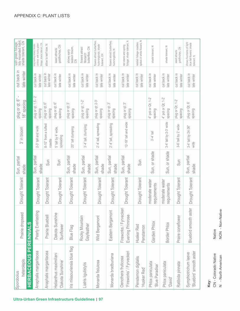
APPENDIX C: PLANT LISTS
Ultra-Urban Green Infrastructure Guidelines
Stre
etsi
de S
torm
wat
er P
lant
er a
nd B
umpo
ut S
torm
wat
er P
lant
er P
lant
Lis
t
Scie
ntifi
c N
ame
Com
mon
Nam
eW
ater
Nee
dsM
aint
enan
ceC
omm
ents
Expo
sure
Sun/
Shad
eSi
ze
H
eigh
t + S
prea
d
Rec
omm
ende
d C
onta
iner
Siz
e +
Spac
ing
GR
ASS
ESAn
drop
ogon
gera
rdii
‘Dan
cing W
ind’
Danc
ing W
ind
Big B
lueste
mW
inter
And
ropo
gon
gera
rdii ‘
P003
S’W
indwa
lker
Big B
lueste
m
Wint
er C
alama
gros
tis x
acuti
flora
‘Kar
l For
ester
’Fe
ather
Ree
d Gra
ss
Boute
loua g
racil
is ‘B
londe
Am
bition
’Bl
onde
Amb
ition
Gram
a Gra
ss
Panic
um vi
rgatu
m ‘H
ot Ro
d’Ho
t Rod
Sw
itchg
rass
Panic
um vi
rgatu
m ’N
orthw
ind’
North
wind
Swi
tchgr
ass
Schiz
achir
ium sc
opar
ium
‘Pra
irie B
lues’
Prair
ie Bl
ues
Lttle
Blue
stem
Muhle
nber
gia re
verch
oni
‘Und
aunte
d’Un
daun
ted R
uby
Muhly
Panic
um vi
rgatu
m ‘P
rairie
Sk
y’Pr
airie
Sky
Desc
hamp
sia ca
espit
osa
Tufte
d Hair
Gra
ss
Drou
ght T
olera
nt4’
in blo
om;
rhizo
matou
splu
g or q
t; 2-
3’ sp
acing
cut b
ack i
n lat
e wint
erre
d fall
color
; CN
Powd
er bl
ue
foliag
e; CN
Gree
ns up
early
sp
ing; N
ON
Stra
w ye
llow
seed
he
ads;
CN
redd
ish su
mmer
an
d fall
folia
ge; C
N
forma
l upr
ight
foliag
e; CN
steel
blue fi
ne-
textur
ed fo
liage
; CN
blue s
umme
r foli
age,
red w
inter
folia
ge,
CN foliag
e loo
ks go
od
year
roun
d; re
d fall
flo
wers,
N
Shad
e tole
rant;
CN
cut b
ack i
n lat
e wint
er
cut b
ack i
n lat
e wint
ercu
t bac
k in
late w
inter
cut b
ack i
n lat
e wint
er
cut b
ack i
n lat
e wint
er
cut b
ack i
n lat
e wint
ercu
t bac
k in
late w
inter
cut b
ack i
n lat
e wint
er
cut b
ack i
n lat
e wint
er
plug o
r qt;
2-3’
spac
ing
plug o
r qt;
2-3’
spac
ingplu
g or q
t; 2-
3’ sp
acing
plug o
r qt;
6” -
18” s
pacin
g
plug o
r qt;
6” -
18” s
pacin
g
plug o
r qt;
6” -
18” s
pacin
g
plug o
r qt;
6” -
18” s
pacin
g
plug o
r qt;
4’ sp
acing
plug o
r qt;
4’ sp
acing
4’ in
bloom
; rh
izoma
tous
2-4’
heigh
t; 18
” -
2’ sp
read
Sun
Sun
Sun,
shad
e
3-4’
heigh
t
18” i
n bloo
m
4-5’
in bl
oom
4-5’
in bl
oom
4-5’
in bl
oom
3’ in
bloo
m
3’ in
bloo
m
Sun,
filter
ed
shad
e Sun
Sun
Sun
Sun
Sun
Sun
Drou
ght T
olera
nt
Drou
ght T
olera
nt
Drou
ght T
olera
nt
Drou
ght T
olera
nt
Drou
ght T
olera
nt
Drou
ght T
olera
nt
Drou
ght T
olera
nt
Mesic
Xeric
Key
:C
N -
Col
orad
o N
ativ
e
N
- Nor
th A
mer
ican
Nat
ive
NO
N -
Non
-Nat
ive
96
APPENDIX C: PLANT LISTS
Ultra-Urban Green Infrastructure Guidelines
Drou
ght T
olera
nt3’
in blo
omcu
t bac
k in
late w
inter
lush g
reen
folia
ge;
tidy m
ound
ed ha
bit;
shad
e tole
rant,
CN
cut b
ack i
n lat
e wint
erlon
g las
ting s
ilver
y bloo
ks
contr
ast
with
bush
y gre
en
foliag
e; sh
ade t
olera
nt, C
N
allow
to se
lf sow
; N
seed
attra
cts
goldfi
nche
s, CN
show
y ear
ly se
ason
bloo
m,
CN flowe
rs att
ract
Mona
rch
butte
rflies
, CN
flowe
rs att
ract
butte
rflies
, hu
mming
birds
; sha
de
toler
ant,
CN
flowe
rs att
ract
butte
rflies
, hu
mming
birds
; N
redd
ish fo
liage
rose
ttes;
spike
s of w
hite fl
ower
s, N
red s
tems a
nd sp
ring
foliag
e; sh
ade t
olera
nt, N
shad
e tole
rant,
N
shad
e tole
rant,
N
seed
attra
cts
goldfi
nche
s, CN
show
y fou
ntains
of lig
ht blu
e fall
flowe
rs; sh
ade
toler
ant,
N
cut b
ack i
n lat
e wint
er
cut b
ack i
n lat
e wint
er
cut b
ack i
n lat
e wint
er
cut b
ack i
n lat
e wint
er
cut b
ack i
n lat
e wint
er
cut b
ack i
n lat
e wint
er
cut b
ack i
n lat
e wint
er
cut b
ack i
n lat
e wint
er
cut b
ack i
n lat
e wint
er
cut b
ack i
n lat
e wint
er
cut b
ack i
n lat
e wint
er
cut b
ack i
n lat
e wint
er
plug o
r qt;
6” -
18” s
pacin
g
plug o
r qt;
1.5 -
2’ sp
acing
plug o
r qt;
6”
spac
ingplu
g or q
t; 6”
sp
acing
plug o
r qt;
3’ sp
acing
plug o
r qt;
3’ sp
acing
plug o
r qt;
3’ sp
acing
4” po
t or Q
t; 1-
2’ sp
acing
4” po
t or Q
t; 1-
2’ sp
acing
plug o
r Qt;
1-2’
spac
ing
plug o
r Qt;
6’ sp
acing
plug o
r qt;
1-2’
spac
ing
plug o
r qt;
2-3’
spac
ing
Sun,
parti
al sh
ade
Sun,
parti
al sh
ade
Sun,
parti
al sh
ade
Sun,
parti
al sh
ade
Sun,
parti
al sh
ade
Sun,
parti
al sh
ade
Sun,
parti
al sh
ade
Sun,
parti
al sh
ade
Sun,
or sh
ade
Sun,
or sh
ade
2-3’
tall a
nd w
ide
8-10
” fro
m a t
ufted
ro
sette
5’ tal
l by 4
’ wide
, sp
read
ing
20” t
all cl
umpin
g
3’-4’
tall, c
lumpin
g
3’-4’
tall
2’-4’
tall, s
prea
ding
2’-4’
tall, s
prea
ding
12-1
8” ta
ll and
wide
3-4’
tall b
y 2-3
’ wide
3-4’
tall b
y 24-
36”
wide3-6’
tall b
y 2’ w
ide
Sun
Sun
Drou
ght T
olera
nt
Drou
ght T
olera
nt
Drou
ght T
olera
nt
Drou
ght T
olera
nt
Drou
ght T
olera
nt
Drou
ght T
olera
nt
Drou
ght T
olera
nt
Drou
ght T
olera
nt
Drou
ght T
olera
nt
mode
rate
water
re
quire
ments
mode
rate
water
re
quire
ments
Drou
ght T
olera
nt
Drou
ght T
olera
nt
Key
:C
N -
Col
orad
o N
ativ
e
N
- Nor
th A
mer
ican
Nat
ive
NO
N -
Non
-Nat
ive
Anap
halis
mar
garit
acea
Anap
halis
mar
garit
acea
Helia
nthus
max
imilia
ni ‘D
akota
Sun
shine
’
Iris m
issou
riens
is blu
e flag
Liatri
s ligu
listyl
is
Mona
rda fi
stulos
a
Mona
rda b
radb
urian
a
Oeno
thera
fruti
cosa
‘Fi
rewo
rks’ /
Fyrve
cker
i
Spor
obolu
she
terole
pisPr
airie
drop
seed
Pear
ly Ev
erlas
ting
Prair
ie Bl
uebe
ll
Dako
ta Su
nshin
e Su
nflow
er
Rock
y Mou
ntain
Gayfe
ather
Firew
orks
/ Fy
rveck
eri
Even
ing P
rimro
se
Wild
Ber
gamo
nt
Easte
rn B
erga
mont
Blue
Flag
HER
BA
CEO
US
PER
ENN
IALS
Pens
temon
digit
alis
‘Hus
ker R
ed’
Husk
er R
edPe
nstam
onPh
lox pa
nicula
ta‘B
lue P
arad
ise’
Gard
en P
hlox
Phlox
panic
ulata
‘Dav
id’Bo
rder
Phlo
x
Symp
hiotri
chum
laev
e ‘B
luebir
d’ sm
ooth
aster
Blue
bird s
mooth
aster
Ratib
ida pi
nnata
Prair
e con
eflow
er
Sun
Sun
97

APPENDIX C: PLANT LISTS
Ultra-Urban Green Infrastructure Guidelines
cut b
ack a
fter
sprin
g bloo
m
bulb
with
show
y blu
e flow
ers m
id sp
ring;
shad
e tol
eran
t NON
silve
r foli
age;
oran
ge
and p
urple
summ
er
bloom
; CN
long b
loomi
ng
cream
y whit
e flow
er,
tidy h
abit,
CN
Whit
e ear
ly su
mmer
flo
wers
ripen
to fe
ather
y pin
k see
d hea
ds sh
owy
when
back
lit, C
NDe
nse m
ound
ed ha
bit,
clean
gray
-gre
en fo
liage
, fru
it for
wild
life, C
N
Redd
ish fa
ll foli
age,
red b
errie
s, sp
read
ing
habit
, CN
Shad
e tole
rant,
NON
prun
e to s
hape
in
late w
inter
prun
e to s
hape
in
late w
inter
prun
e to s
hape
in
late w
inter
prun
e to s
hape
in
late w
inter
prun
e to s
hape
in
late w
inter
prun
e to s
hape
in
late w
inter
Bulbs
, clus
tered
in
grou
ps 9
bulbs
/SF
#1 or
#5 co
ntaine
r; 1-
2’ sp
acing
#1 or
#5 co
ntaine
r
#1 or
#5 co
ntaine
r
#1 or
#5 co
ntaine
r
#1 or
#5 co
ntaine
r
#1 or
#5 co
ntaine
r
Sun,o
r sh
ade
Sun,
parti
al sh
ade Su
n
Sun
Sun
Sun
Sun,
parti
al sh
ade
12-1
8” ta
ll, clu
mping
2-3’
tall a
nd w
ide
2-3’
tall a
nd w
ide
3’-4’
tall a
nd w
ide
3’ ta
ll X 6/
8’ wi
de
3’ ta
ll X 6/
8’ wi
de
Drou
ght T
olera
nt
Drou
ght T
olera
nt
Drou
ght T
olera
nt
Xeric
Xeric
Xeric
Mode
rate
Key
:C
N -
Col
orad
o N
ativ
e
N
- Nor
th A
mer
ican
Nat
ive
NO
N -
Non
-Nat
ive
Cama
ssia
leich
tlinii
‘Blue
Dan
ube’
Amor
pha C
anes
cens
Dasip
hora
(Pote
ntilla
) Fr
utico
sa va
r. da
huric
a ‘pr
aire s
how’
Fallu
gia P
arad
oxa
Prun
us be
ssey
i ‘Paw
nee
Butte
s’Rh
us tr
iloba
ta ‘A
utumn
Am
ber’
Spire
a betu
lufoli
a‘To
r Gold
’
Blue
Dan
ube W
ild
Hyac
inth
Lead
plant
Apac
he P
lume
Glow
Girl
Spire
a
Pawn
ee B
uttes
Sa
nd C
herry
Autum
n Amb
er
Skun
kbus
h Sum
ac
‘Pra
ire S
now’
W
hite C
inque
foil
BU
LBS
SHR
UB
S
98

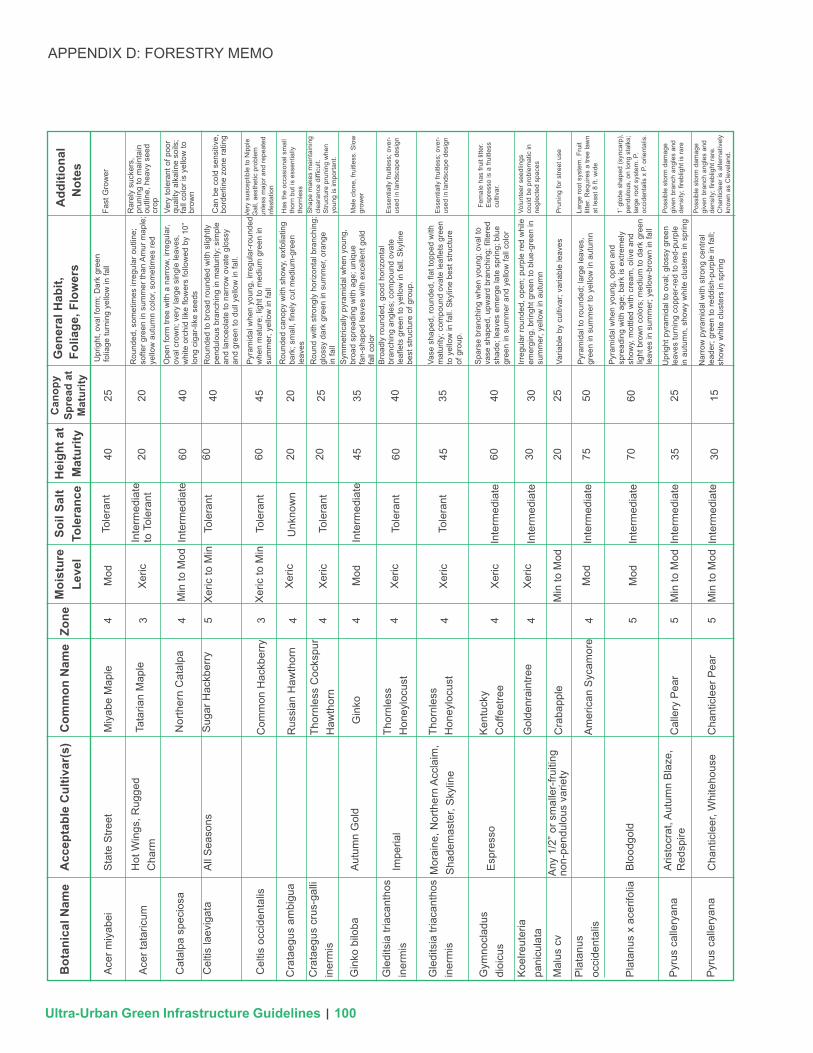
APPENDIX D: FORESTRY MEMO
Ultra-Urban Green Infrastructure Guidelines
The following list of tree species are approved for planting in green infrastructure stormwater facilities within Denver rights-of-way.
Please note that this list may change overtime based on experience and species performance.
City Forester issued planting and removal permits are required prior to the removal or planting of trees within Denver rights-of-way.
Trees not included in this list may be permitted on a case-by-case basis.
Please contact the Office of the City Forester for more information on planting trees within stormwater facilities or to request tree permits.
Shading indicates species suitable for planting under overhead utilities. These varieties should only be planted in situations where overhead growth restrictions exist.
• 35’ between shade trees
• 25’ between ornamental trees
• 30’ from curb at intersections
• 20’ from street lights
• 10’ from alleys, driveways & fire hydrants
DENVER’S APPROVED STORMWATER FACILITY STREET TREE LIST
The following are standard spacing requirements for street trees in Denver:
Last updated 2.15.15
TREE LIST LEGEND
99
APPENDIX D: FORESTRY MEMO
Ultra-Urban Green Infrastructure Guidelines
vB
otan
ical
Nam
e
Ace
r miy
abei
Sta
te S
treet
Miy
abe
Map
leM
od
Mod
Mod
Mod
Xer
ic
Xer
ic
Xer
ic
Xer
ic
Xer
ic
Xer
ic
Xer
ic
Min
to M
od
Inte
rmed
iate
to
Tol
eran
t
Inte
rmed
iate
Inte
rmed
iate
Inte
rmed
iate
Inte
rmed
iate
Inte
rmed
iate
Inte
rmed
iate
Inte
rmed
iate
Inte
rmed
iate
Tole
rant
Tole
rant
Tole
rant
Tole
rant
Tole
rant
Tole
rant
Unk
now
n
Xer
ic to
Min
Xer
ic to
Min
440
40 40 40 4025U
prig
ht, o
val f
orm
; Dar
k gr
een
folia
ge tu
rnin
g ye
llow
in fa
llFa
st G
row
er
Rar
ely
suck
ers,
pr
unin
g to
mai
ntai
n ou
tline
, hea
vy s
eed
crop
Very
tole
rant
of p
oor
qual
ity a
lkal
ine
soils
; fa
ll co
lor i
s ye
llow
to
brow
n
Can
be
cold
sen
sitiv
e,
bord
erlin
e zo
ne ra
ting
Very
sus
cept
ible
to N
ippl
e G
all,
aest
hetic
pro
blem
un
less
maj
or a
nd re
peat
ed
infe
stat
ion
Has
the
occa
sion
al s
mal
l th
orn
but i
s es
sent
ially
th
ornl
ess
Sha
pe m
akes
mai
ntai
ning
cl
eara
nce
diffi
cult.
S
truct
ure
prun
ing
whe
n yo
ung
is im
porta
nt.
Mal
e cl
one,
frui
tless
. Slo
w
grow
er
Ess
entia
lly fr
uitle
ss; o
ver-
used
in la
ndsc
ape
desi
gn
Ess
entia
lly fr
uitle
ss; o
ver-
used
in la
ndsc
ape
desi
gn
Fem
ale
has
fruit
litte
r. E
spre
sso
is a
frui
tless
cu
ltiva
r.
Volu
ntee
r see
dlin
gs
coul
d be
pro
blem
atic
in
negl
ecte
d sp
aces
Pru
ning
for s
treet
use
Larg
e ro
ot s
yste
m. F
ruit
litte
r. R
equi
res
a tre
e la
wn
at le
ast 8
ft. w
ide
1’ g
lobe
sha
ped
(syn
carp
), pe
ndul
ous,
on
long
sta
lks;
la
rge
root
sys
tem
. P.
occi
dent
alis
x P
. orie
ntal
is.
Pos
sibl
e st
orm
dam
age
give
n br
anch
ang
les
and
dens
ity; fi
rebl
ight
is ra
re
Pos
sibl
e st
orm
dam
age
give
n br
anch
ang
les
and
dens
ity; fi
rebl
ight
rare
. C
hant
icle
er is
alte
rnat
ivel
y kn
own
as C
leve
land
.
Rou
nded
, som
etim
es ir
regu
lar o
utlin
e;
softe
r gre
en in
sum
mer
than
Am
ur m
aple
; ye
llow
aut
umn
colo
r, so
met
imes
red
Ope
n fo
rm tr
ee w
ith a
nar
row
, irr
egul
ar,
oval
cro
wn;
ver
y la
rge
sing
le le
aves
, w
hite
orc
hid
like
flow
ers
follo
wed
by
10”
long
cig
ar-li
ke s
eeds
Rou
nded
to b
road
roun
ded
with
slig
htly
pe
ndul
ous
bran
chin
g in
mat
urity
; sim
ple
and
lanc
eola
te to
nar
row
ova
te g
loss
y an
d gr
een
to d
ull y
ello
w in
fall.
Pyr
amid
al w
hen
youn
g, ir
regu
lar-
roun
ded
whe
n m
atur
e; li
ght t
o m
ediu
m g
reen
in
sum
mer
, yel
low
in fa
ll
Rou
nded
can
opy
with
sho
wy,
exf
olia
ting
bark
; sm
all,
finel
y cu
t med
ium
-gre
en
leav
esR
ound
with
stro
ngly
hor
izon
tal b
ranc
hing
; gl
ossy
dar
k gr
een
in s
umm
er, o
rang
e in
fall
Sym
met
rical
ly p
yram
idal
whe
n yo
ung,
br
oad
spre
adin
g w
ith a
ge; u
niqu
e fa
n-sh
aped
leav
es w
ith e
xcel
lent
gol
d fa
ll co
lor
Bro
adly
roun
ded,
goo
d ho
rizon
tal
bran
chin
g an
gles
; com
poun
d ov
ate
leafl
ets
gree
n to
yel
low
in fa
ll. S
kylin
e be
st s
truct
ure
of g
roup
.
Vase
sha
ped,
roun
ded,
flat
topp
ed w
ith
mat
urity
; com
poun
d ov
ate
leafl
ets
gree
n to
yel
low
in fa
ll. S
kylin
e be
st s
truct
ure
of g
roup
.
Spa
rse
bran
chin
g w
hen
youn
g; o
val t
o va
se s
hape
d, u
pwar
d br
anch
ing;
filte
red
shad
e; le
aves
em
erge
late
spr
ing;
blu
e gr
een
in s
umm
er a
nd y
ello
w fa
ll co
lor
Pyr
amid
al w
hen
youn
g, o
pen
and
spre
adin
g w
ith a
ge; b
ark
is e
xtre
mel
y sh
owy,
mot
tled
with
cre
am, o
live
and
light
bro
wn
colo
rs; m
ediu
m to
dar
k gr
een
leav
es in
sum
mer
; yel
low
-bro
wn
in fa
ll
Irreg
ular
roun
ded,
ope
n; p
urpl
e re
d w
hile
em
ergi
ng, b
ringh
t gre
en to
blu
e-gr
een
in
sum
mer
, yel
low
in a
utum
n
Pyr
amid
al to
roun
ded;
larg
e le
aves
, gr
een
in s
umm
er to
yel
low
in a
utum
n
Upr
ight
pyr
amid
al to
ova
l; gl
ossy
gre
en
leav
es tu
rnin
g co
pper
-red
to re
d-pu
rple
in
aut
umn,
sho
wy
whi
te c
lust
ers
in s
prin
g
Nar
row
pyr
amid
al w
ith s
trong
cen
tral
lead
er; g
reen
to re
ddis
h-pu
rple
in fa
ll;
show
y w
hite
clu
ster
s in
spr
ing
Varia
ble
by c
ultiv
ar; v
aria
ble
leav
es
25
2020
2020
20 45
45
60 45 60
60
3030
20 7550
35
35 35
70 3015
60 60 60
4 4 4 4 4 4 4 4 45 5 5 53 3
Tata
rian
Map
le
Nor
ther
n C
atal
pa
Sug
ar H
ackb
erry
Com
mon
Hac
kber
ry
Rus
sian
Haw
thor
n
Thor
nles
s C
ocks
pur
Haw
thor
n
Thor
nles
s H
oney
locu
st
Thor
nles
s H
oney
locu
st
Ken
tuck
y C
offe
etre
e
Am
eric
an S
ycam
ore
Cal
lery
Pea
r
Cha
ntic
leer
Pea
r
Gol
denr
aint
ree
Cra
bapp
le
Gin
ko
All
Sea
sons
Aut
umn
Gol
d
Impe
rial
Esp
ress
o
Mor
aine
, Nor
ther
n A
ccla
im,
Sha
dem
aste
r, S
kylin
e
Any
1/2
” or s
mal
ler-
fruiti
ng
non-
pend
ulou
s va
riety
Aris
tocr
at, A
utum
n B
laze
, R
edsp
ire
Cha
ntic
leer
, Whi
teho
use
Blo
odgo
ld
Hot
Win
gs, R
ugge
d C
harm
Ace
r tat
aric
um
Cel
tis la
evig
ata
Cel
tis o
ccid
enta
lis
Cra
taeg
us a
mbi
gua
Gin
ko b
iloba
Cra
taeg
us c
rus-
galli
in
erm
is
Gle
dits
ia tr
iaca
ntho
s in
erm
is
Gle
dits
ia tr
iaca
ntho
s in
erm
is
Gym
nocl
adus
di
oicu
s
Koe
lreut
eria
pa
nicu
lata
Mal
us c
v
Pla
tanu
s oc
cide
ntal
is
Pla
tanu
s x
acer
ifolia
Pyr
us c
alle
ryan
a
Pyr
us c
alle
ryan
a
Cat
alpa
spe
cios
a
Acc
epta
ble
Cul
tivar
(s)
Com
mon
Nam
eG
ener
al H
abit,
Fo
liage
, Flo
wer
sA
dditi
onal
N
otes
Moi
stur
e Le
vel
Soil
Salt
Tole
ranc
eH
eigh
t at
Mat
urity
Can
opy
Spre
ad a
t M
atur
ityZo
ne
Min
to M
od
Min
to M
od
Min
to M
od
25 25
100

APPENDIX D: FORESTRY MEMO
Ultra-Urban Green Infrastructure Guidelines
vB
otan
ical
Nam
e
Que
rcus
bic
olor
Sw
amp
Whi
te O
ak
Mod
Mod
Mod
Xer
ic
Xer
ic
Min
Inte
rmed
iate
to
Sen
sitiv
e
Inte
rmed
iate
to
Tol
eran
t
Inte
rmed
iate
Inte
rmed
iate
Tole
rant
Mod
Tole
rant
Unk
now
n
Unk
now
n
Unk
now
n
Unk
now
n
Unk
now
n
Unk
now
n
Unk
now
n
Inte
rmed
iate
Xer
ic to
Min
Xer
ic to
Min
Xer
ic to
Min
Xer
ic to
Min
450
50 45 30 3050
Bro
ad, r
ound
ed, o
pen
typi
cally
has
sh
orte
r tru
nk; b
ark
is a
ttrac
tive,
gra
yish
-br
own,
and
flak
y; L
ustro
us, l
eath
ery
dark
gre
en in
sum
mer
, yel
low
ish
in th
e fa
ll an
d so
met
imes
pur
ple-
red
Aco
rns
in h
eavy
cro
ps
ever
y 3-
5 ye
ars
Aco
rns
Long
, sle
nder
aco
rns
Hyb
rid o
f Q. r
obur
x Q
. m
acro
carp
a. A
corn
s.
Sto
rm d
amag
e an
oc
casi
onal
con
cern
. Fo
rmer
ly k
now
n as
S
opho
ra ja
poni
ca.
Reg
ular
pru
ning
to
mai
ntai
n si
ngle
ste
m, a
nd
avoi
d dr
oopi
ng lo
wer
lim
bs
Win
ter d
essi
catio
n m
ay b
e pr
oble
mat
ic, l
iste
d cu
ltiva
rs
show
goo
d re
sist
ance
to
Dut
ch E
lm D
isea
se
Nee
ds p
runi
ng fo
r sin
gle
trunk
; lea
fs o
ut e
arly
and
fre
quen
tly s
uffe
r fro
st
dam
age
in s
prin
g
DE
D a
nd E
LB re
sist
ant
DE
D re
sist
ant
DE
D a
nd E
LB re
sist
ant
Pru
ning
for s
truct
ure
Ada
ptab
le to
urb
an
cond
ition
s, n
ot p
rove
n in
C
olor
ado
envi
ronm
ent f
or
snow
load
sIn
sign
ifica
nt fr
uit l
itter
; pr
unin
g fo
r stru
ctur
e an
d sn
ow lo
ad; m
ost c
old
hard
y cu
ltiva
r
Wea
kly
pyra
mid
al to
ova
l in
yout
h,
broa
dly
roun
ded
and
open
with
age
; le
athe
ry, l
ustro
us d
ark
gree
n in
sum
mer
, ye
llow
-gre
en to
yel
low
-bro
wn
in a
utum
n
Col
umna
r cul
tivar
s av
aila
ble,
but
usu
ally
br
oadl
y ro
und
and
oval
; Fol
iage
dar
k gr
een
to b
lue-
gree
n in
sum
mer
, bro
wn
in a
utum
n
Fast
gro
win
g. W
hen
youn
g is
a p
yram
idal
tre
e th
at m
atur
es in
to a
wid
e, o
val f
orm
w
ith a
stro
ng c
entra
l lea
der.
Leav
es a
re a
de
ep, g
loss
y gr
een
Ova
l to
roun
d, u
prig
ht s
prad
ing
bran
ches
, fre
quen
tly w
ider
than
tall;
lust
rous
brig
ht
gree
n in
sum
mer
, yel
low
ish
in fa
ll, la
te to
tu
rn c
olor
in fa
llU
prig
ht th
en ro
unde
d an
d sp
read
ing;
si
mpl
e da
rk g
reen
to y
ello
w in
fall;
cr
eam
y w
hite
pan
icle
s in
Jun
e
Spr
eadi
ng ro
unde
d va
se; g
reen
leav
es,
no a
utum
n co
lor;
show
y, w
hite
flow
ers
in
early
sum
mer
Bro
adly
vas
e-sh
aped
; gre
en le
aves
in
sum
mer
, yel
low
in a
utum
n
Sim
ilar i
n ou
tline
to A
mer
ican
elm
; dar
k gr
een
sum
mer
folia
ge; y
ello
w in
fall
Upr
ight
, arc
hing
vas
e re
sem
blin
g A
mer
ican
Elm
; dar
k gr
een
in s
umm
er;
yello
w to
red
in a
utum
n
Vase
-sha
ped;
larg
e le
aves
em
erge
with
re
d/or
ange
tint
, yel
low
in a
utum
n
Fast
est g
row
ing;
upr
ight
vas
e; m
ediu
m
gree
n to
yel
low
Upr
ight
arc
hing
bra
nche
s fo
rmin
g va
se
shap
e; ta
ller a
nd n
arro
wer
than
vill
age
gr
een;
gre
en to
yel
low
in fa
ll
Nar
row
upr
ight
vas
e; m
ediu
m g
reen
to
yello
w/o
rang
e in
fall;
sm
alle
r lea
ves
than
ot
her Z
elko
vas.
Fast
gro
win
g, u
prig
ht ro
unde
d va
se w
ith
stra
ight
er tr
unk;
dar
k gr
een
to v
aria
ble
red
in a
utum
n
20
6060
1515
25 70
40
35 45 40 4040
50 5045
451560 40
55 70 40
4 4 4 4 4 4 53 3 3 5 5 5 5
Bur
Oak
Eng
lish
Oak
Mac
Dan
iel’s
Oak
Japa
nese
P
agod
atre
e;
Sch
olar
tree
Chi
na S
now
Lila
c
Japa
nese
Tre
e Li
lac Ja
pane
se
Elm
Alle
e La
ceba
rk
Elm
Pro
spec
tor E
lm
Japa
nese
Zel
kova
Japa
nese
Zel
kova
Japa
nese
Zel
kova
Japa
nese
Zel
kova
Am
eric
an E
lm
Bra
ndon
; New
Har
mon
y;
Prin
ceto
n; V
alle
y Fo
rge
Dis
cove
ry
Pro
spec
tor
Gre
en V
eil
Em
er II
Hal
ka
Villa
ge G
reen
Mus
ashi
no
Que
rcus
m
acro
carp
a
Que
rcus
x
mac
dani
elli
Her
itage
Reg
ent
Mor
ton
Ivor
y S
ilk
Sty
phon
olob
ium
japo
nicu
m
Syr
inga
pek
ines
is
Ulm
us a
mer
ican
a
Syr
inga
retic
ulat
a
Ulm
us ja
poni
ca
Ulm
us p
arvi
folia
Ulm
us w
ilson
iana
Zelk
ova
serr
ata
Zelk
ova
serr
ata
Zelk
ova
serr
ata
Zelk
ova
serr
ata
Que
rcus
robu
r
Acc
epta
ble
Cul
tivar
(s)
Com
mon
Nam
eG
ener
al H
abit,
Fo
liage
, Flo
wer
sA
dditi
onal
N
otes
Moi
stur
e Le
vel
Soil
Salt
Tole
ranc
eH
eigh
t at
Mat
urity
Can
opy
Spre
ad a
t M
atur
ityZo
ne
Min
to M
od
Min
to M
od
Min
to M
od
Min
to M
od
Min
to M
od
35
101